CN115348845A - Electrosurgical instruments, generators and equipment - Google Patents
Electrosurgical instruments, generators and equipmentDownload PDFInfo
- Publication number
- CN115348845A CN115348845ACN202080083913.8ACN202080083913ACN115348845ACN 115348845 ACN115348845 ACN 115348845ACN 202080083913 ACN202080083913 ACN 202080083913ACN 115348845 ACN115348845 ACN 115348845A
- Authority
- CN
- China
- Prior art keywords
- signal
- electrical signal
- energy
- microwave
- instrument
- Prior art date
- Legal status (The legal status is an assumption and is not a legal conclusion. Google has not performed a legal analysis and makes no representation as to the accuracy of the status listed.)
- Pending
Links
Images


Classifications
- A—HUMAN NECESSITIES
- A61—MEDICAL OR VETERINARY SCIENCE; HYGIENE
- A61B—DIAGNOSIS; SURGERY; IDENTIFICATION
- A61B18/00—Surgical instruments, devices or methods for transferring non-mechanical forms of energy to or from the body
- A61B18/04—Surgical instruments, devices or methods for transferring non-mechanical forms of energy to or from the body by heating
- A61B18/12—Surgical instruments, devices or methods for transferring non-mechanical forms of energy to or from the body by heating by passing a current through the tissue to be heated, e.g. high-frequency current
- A61B18/14—Probes or electrodes therefor
- A61B18/1442—Probes having pivoting end effectors, e.g. forceps
- A61B18/1445—Probes having pivoting end effectors, e.g. forceps at the distal end of a shaft, e.g. forceps or scissors at the end of a rigid rod
- A—HUMAN NECESSITIES
- A61—MEDICAL OR VETERINARY SCIENCE; HYGIENE
- A61B—DIAGNOSIS; SURGERY; IDENTIFICATION
- A61B18/00—Surgical instruments, devices or methods for transferring non-mechanical forms of energy to or from the body
- A61B18/04—Surgical instruments, devices or methods for transferring non-mechanical forms of energy to or from the body by heating
- A61B18/12—Surgical instruments, devices or methods for transferring non-mechanical forms of energy to or from the body by heating by passing a current through the tissue to be heated, e.g. high-frequency current
- A61B18/1206—Generators therefor
- A—HUMAN NECESSITIES
- A61—MEDICAL OR VETERINARY SCIENCE; HYGIENE
- A61B—DIAGNOSIS; SURGERY; IDENTIFICATION
- A61B18/00—Surgical instruments, devices or methods for transferring non-mechanical forms of energy to or from the body
- A61B18/04—Surgical instruments, devices or methods for transferring non-mechanical forms of energy to or from the body by heating
- A61B18/12—Surgical instruments, devices or methods for transferring non-mechanical forms of energy to or from the body by heating by passing a current through the tissue to be heated, e.g. high-frequency current
- A61B18/14—Probes or electrodes therefor
- A—HUMAN NECESSITIES
- A61—MEDICAL OR VETERINARY SCIENCE; HYGIENE
- A61B—DIAGNOSIS; SURGERY; IDENTIFICATION
- A61B18/00—Surgical instruments, devices or methods for transferring non-mechanical forms of energy to or from the body
- A61B18/18—Surgical instruments, devices or methods for transferring non-mechanical forms of energy to or from the body by applying electromagnetic radiation, e.g. microwaves
- A61B18/1815—Surgical instruments, devices or methods for transferring non-mechanical forms of energy to or from the body by applying electromagnetic radiation, e.g. microwaves using microwaves
- A—HUMAN NECESSITIES
- A61—MEDICAL OR VETERINARY SCIENCE; HYGIENE
- A61N—ELECTROTHERAPY; MAGNETOTHERAPY; RADIATION THERAPY; ULTRASOUND THERAPY
- A61N7/00—Ultrasound therapy
- A—HUMAN NECESSITIES
- A61—MEDICAL OR VETERINARY SCIENCE; HYGIENE
- A61N—ELECTROTHERAPY; MAGNETOTHERAPY; RADIATION THERAPY; ULTRASOUND THERAPY
- A61N7/00—Ultrasound therapy
- A61N7/02—Localised ultrasound hyperthermia
- A—HUMAN NECESSITIES
- A61—MEDICAL OR VETERINARY SCIENCE; HYGIENE
- A61B—DIAGNOSIS; SURGERY; IDENTIFICATION
- A61B18/00—Surgical instruments, devices or methods for transferring non-mechanical forms of energy to or from the body
- A61B2018/00053—Mechanical features of the instrument of device
- A61B2018/00107—Coatings on the energy applicator
- A61B2018/0013—Coatings on the energy applicator non-sticking
- A—HUMAN NECESSITIES
- A61—MEDICAL OR VETERINARY SCIENCE; HYGIENE
- A61B—DIAGNOSIS; SURGERY; IDENTIFICATION
- A61B18/00—Surgical instruments, devices or methods for transferring non-mechanical forms of energy to or from the body
- A61B2018/00053—Mechanical features of the instrument of device
- A61B2018/00184—Moving parts
- A61B2018/00196—Moving parts reciprocating lengthwise
- A—HUMAN NECESSITIES
- A61—MEDICAL OR VETERINARY SCIENCE; HYGIENE
- A61B—DIAGNOSIS; SURGERY; IDENTIFICATION
- A61B18/00—Surgical instruments, devices or methods for transferring non-mechanical forms of energy to or from the body
- A61B2018/00053—Mechanical features of the instrument of device
- A61B2018/00184—Moving parts
- A61B2018/00202—Moving parts rotating
- A—HUMAN NECESSITIES
- A61—MEDICAL OR VETERINARY SCIENCE; HYGIENE
- A61B—DIAGNOSIS; SURGERY; IDENTIFICATION
- A61B18/00—Surgical instruments, devices or methods for transferring non-mechanical forms of energy to or from the body
- A61B2018/00315—Surgical instruments, devices or methods for transferring non-mechanical forms of energy to or from the body for treatment of particular body parts
- A61B2018/00345—Vascular system
- A—HUMAN NECESSITIES
- A61—MEDICAL OR VETERINARY SCIENCE; HYGIENE
- A61B—DIAGNOSIS; SURGERY; IDENTIFICATION
- A61B18/00—Surgical instruments, devices or methods for transferring non-mechanical forms of energy to or from the body
- A61B2018/00571—Surgical instruments, devices or methods for transferring non-mechanical forms of energy to or from the body for achieving a particular surgical effect
- A61B2018/00577—Ablation
- A—HUMAN NECESSITIES
- A61—MEDICAL OR VETERINARY SCIENCE; HYGIENE
- A61B—DIAGNOSIS; SURGERY; IDENTIFICATION
- A61B18/00—Surgical instruments, devices or methods for transferring non-mechanical forms of energy to or from the body
- A61B2018/00571—Surgical instruments, devices or methods for transferring non-mechanical forms of energy to or from the body for achieving a particular surgical effect
- A61B2018/00601—Cutting
- A—HUMAN NECESSITIES
- A61—MEDICAL OR VETERINARY SCIENCE; HYGIENE
- A61B—DIAGNOSIS; SURGERY; IDENTIFICATION
- A61B18/00—Surgical instruments, devices or methods for transferring non-mechanical forms of energy to or from the body
- A61B2018/00571—Surgical instruments, devices or methods for transferring non-mechanical forms of energy to or from the body for achieving a particular surgical effect
- A61B2018/00607—Coagulation and cutting with the same instrument
- A—HUMAN NECESSITIES
- A61—MEDICAL OR VETERINARY SCIENCE; HYGIENE
- A61B—DIAGNOSIS; SURGERY; IDENTIFICATION
- A61B18/00—Surgical instruments, devices or methods for transferring non-mechanical forms of energy to or from the body
- A61B2018/00571—Surgical instruments, devices or methods for transferring non-mechanical forms of energy to or from the body for achieving a particular surgical effect
- A61B2018/00619—Welding
- A—HUMAN NECESSITIES
- A61—MEDICAL OR VETERINARY SCIENCE; HYGIENE
- A61B—DIAGNOSIS; SURGERY; IDENTIFICATION
- A61B18/00—Surgical instruments, devices or methods for transferring non-mechanical forms of energy to or from the body
- A61B2018/00571—Surgical instruments, devices or methods for transferring non-mechanical forms of energy to or from the body for achieving a particular surgical effect
- A61B2018/0063—Sealing
- A—HUMAN NECESSITIES
- A61—MEDICAL OR VETERINARY SCIENCE; HYGIENE
- A61B—DIAGNOSIS; SURGERY; IDENTIFICATION
- A61B18/00—Surgical instruments, devices or methods for transferring non-mechanical forms of energy to or from the body
- A61B2018/00636—Sensing and controlling the application of energy
- A61B2018/00773—Sensed parameters
- A61B2018/00779—Power or energy
- A61B2018/00785—Reflected power
- A—HUMAN NECESSITIES
- A61—MEDICAL OR VETERINARY SCIENCE; HYGIENE
- A61B—DIAGNOSIS; SURGERY; IDENTIFICATION
- A61B18/00—Surgical instruments, devices or methods for transferring non-mechanical forms of energy to or from the body
- A61B2018/00636—Sensing and controlling the application of energy
- A61B2018/00773—Sensed parameters
- A61B2018/00791—Temperature
- A61B2018/00797—Temperature measured by multiple temperature sensors
- A—HUMAN NECESSITIES
- A61—MEDICAL OR VETERINARY SCIENCE; HYGIENE
- A61B—DIAGNOSIS; SURGERY; IDENTIFICATION
- A61B18/00—Surgical instruments, devices or methods for transferring non-mechanical forms of energy to or from the body
- A61B2018/00636—Sensing and controlling the application of energy
- A61B2018/00773—Sensed parameters
- A61B2018/00791—Temperature
- A61B2018/00821—Temperature measured by a thermocouple
- A—HUMAN NECESSITIES
- A61—MEDICAL OR VETERINARY SCIENCE; HYGIENE
- A61B—DIAGNOSIS; SURGERY; IDENTIFICATION
- A61B18/00—Surgical instruments, devices or methods for transferring non-mechanical forms of energy to or from the body
- A61B2018/00636—Sensing and controlling the application of energy
- A61B2018/00773—Sensed parameters
- A61B2018/00869—Phase
- A—HUMAN NECESSITIES
- A61—MEDICAL OR VETERINARY SCIENCE; HYGIENE
- A61B—DIAGNOSIS; SURGERY; IDENTIFICATION
- A61B18/00—Surgical instruments, devices or methods for transferring non-mechanical forms of energy to or from the body
- A61B2018/00982—Surgical instruments, devices or methods for transferring non-mechanical forms of energy to or from the body combined with or comprising means for visual or photographic inspections inside the body, e.g. endoscopes
- A—HUMAN NECESSITIES
- A61—MEDICAL OR VETERINARY SCIENCE; HYGIENE
- A61B—DIAGNOSIS; SURGERY; IDENTIFICATION
- A61B18/00—Surgical instruments, devices or methods for transferring non-mechanical forms of energy to or from the body
- A61B2018/00994—Surgical instruments, devices or methods for transferring non-mechanical forms of energy to or from the body combining two or more different kinds of non-mechanical energy or combining one or more non-mechanical energies with ultrasound
- A—HUMAN NECESSITIES
- A61—MEDICAL OR VETERINARY SCIENCE; HYGIENE
- A61B—DIAGNOSIS; SURGERY; IDENTIFICATION
- A61B18/00—Surgical instruments, devices or methods for transferring non-mechanical forms of energy to or from the body
- A61B18/04—Surgical instruments, devices or methods for transferring non-mechanical forms of energy to or from the body by heating
- A61B18/12—Surgical instruments, devices or methods for transferring non-mechanical forms of energy to or from the body by heating by passing a current through the tissue to be heated, e.g. high-frequency current
- A61B18/1206—Generators therefor
- A61B2018/1273—Generators therefor including multiple generators in one device
- A—HUMAN NECESSITIES
- A61—MEDICAL OR VETERINARY SCIENCE; HYGIENE
- A61B—DIAGNOSIS; SURGERY; IDENTIFICATION
- A61B18/00—Surgical instruments, devices or methods for transferring non-mechanical forms of energy to or from the body
- A61B18/04—Surgical instruments, devices or methods for transferring non-mechanical forms of energy to or from the body by heating
- A61B18/12—Surgical instruments, devices or methods for transferring non-mechanical forms of energy to or from the body by heating by passing a current through the tissue to be heated, e.g. high-frequency current
- A61B18/1206—Generators therefor
- A61B2018/128—Generators therefor generating two or more frequencies
- A—HUMAN NECESSITIES
- A61—MEDICAL OR VETERINARY SCIENCE; HYGIENE
- A61B—DIAGNOSIS; SURGERY; IDENTIFICATION
- A61B18/00—Surgical instruments, devices or methods for transferring non-mechanical forms of energy to or from the body
- A61B18/04—Surgical instruments, devices or methods for transferring non-mechanical forms of energy to or from the body by heating
- A61B18/12—Surgical instruments, devices or methods for transferring non-mechanical forms of energy to or from the body by heating by passing a current through the tissue to be heated, e.g. high-frequency current
- A61B18/14—Probes or electrodes therefor
- A61B18/1442—Probes having pivoting end effectors, e.g. forceps
- A61B2018/1452—Probes having pivoting end effectors, e.g. forceps including means for cutting
- A61B2018/1455—Probes having pivoting end effectors, e.g. forceps including means for cutting having a moving blade for cutting tissue grasped by the jaws
- A—HUMAN NECESSITIES
- A61—MEDICAL OR VETERINARY SCIENCE; HYGIENE
- A61B—DIAGNOSIS; SURGERY; IDENTIFICATION
- A61B18/00—Surgical instruments, devices or methods for transferring non-mechanical forms of energy to or from the body
- A61B18/18—Surgical instruments, devices or methods for transferring non-mechanical forms of energy to or from the body by applying electromagnetic radiation, e.g. microwaves
- A61B18/1815—Surgical instruments, devices or methods for transferring non-mechanical forms of energy to or from the body by applying electromagnetic radiation, e.g. microwaves using microwaves
- A61B2018/1823—Generators therefor
- A—HUMAN NECESSITIES
- A61—MEDICAL OR VETERINARY SCIENCE; HYGIENE
- A61B—DIAGNOSIS; SURGERY; IDENTIFICATION
- A61B18/00—Surgical instruments, devices or methods for transferring non-mechanical forms of energy to or from the body
- A61B18/18—Surgical instruments, devices or methods for transferring non-mechanical forms of energy to or from the body by applying electromagnetic radiation, e.g. microwaves
- A61B18/1815—Surgical instruments, devices or methods for transferring non-mechanical forms of energy to or from the body by applying electromagnetic radiation, e.g. microwaves using microwaves
- A61B2018/183—Surgical instruments, devices or methods for transferring non-mechanical forms of energy to or from the body by applying electromagnetic radiation, e.g. microwaves using microwaves characterised by the type of antenna
Landscapes
- Health & Medical Sciences (AREA)
- Life Sciences & Earth Sciences (AREA)
- Surgery (AREA)
- Engineering & Computer Science (AREA)
- Veterinary Medicine (AREA)
- Public Health (AREA)
- Nuclear Medicine, Radiotherapy & Molecular Imaging (AREA)
- General Health & Medical Sciences (AREA)
- Biomedical Technology (AREA)
- Animal Behavior & Ethology (AREA)
- Medical Informatics (AREA)
- Molecular Biology (AREA)
- Heart & Thoracic Surgery (AREA)
- Otolaryngology (AREA)
- Physics & Mathematics (AREA)
- Plasma & Fusion (AREA)
- Electromagnetism (AREA)
- Radiology & Medical Imaging (AREA)
- Surgical Instruments (AREA)
- Laser Surgery Devices (AREA)
Abstract
Description
Translated fromChinese发明领域field of invention
本发明涉及一种用于递送电磁(EM)能量和超声振动来治疗生物组织的电外科器械,所述电外科器械具有用于产生所述超声振动的磁致伸缩超声换能器。本发明还涉及一种用于产生EM能量和用于驱动所述磁致伸缩超声换能器的电信号的电外科发生器。The present invention relates to an electrosurgical instrument for delivering electromagnetic (EM) energy and ultrasonic vibrations to treat biological tissue, the electrosurgical instrument having a magnetostrictive ultrasonic transducer for generating the ultrasonic vibrations. The invention also relates to an electrosurgical generator for generating EM energy and electrical signals for driving said magnetostrictive ultrasound transducer.
发明背景Background of the invention
电外科器械及其相关联的发生器已普遍深入到医院手术室中以用于开放式手术和腹腔镜手术,并且还越来越多地出现在内窥镜检查套件中。在内窥镜手术中,通常穿过内窥镜内部的管腔插入电外科附件。考虑到腹腔镜外科手术的等同的进入通道,这种管腔具有比较窄的孔和较大的长度。Electrosurgical instruments and their associated generators are commonly found in hospital operating rooms for open and laparoscopic procedures, and increasingly also in endoscopy suites. During endoscopic procedures, electrosurgical accessories are typically inserted through a lumen inside the endoscope. Such a lumen has a narrower bore and greater length in view of an equivalent access channel for laparoscopic surgery.
已知可使用射频(RF)能量来切割生物组织。使用RF能量切割的方法使用如下原理进行操作:在电流(受助于细胞的离子内容物和细胞间电解质)通过组织基质时,整个组织上对电子流的阻抗产生热量。当将RF电压施加到组织基质时,在细胞内产生足够的热量以使组织的水分蒸发。由于这种增加的干化,特别是在与所述器械的RF发射区域(本文被称为RF刀片)相邻的在通过组织的整个电流路径中具有最高电流密度之处,与RF刀片的切割极相邻的组织会失去与刀片的直接接触。所施加的电压之后看起来几乎完全落在这个空隙上,所述空隙因此离子化,从而形成等离子体,这与组织相比较具有非常高的体积电阻率。这一差异很重要,因为它将所施加的能量集中到完成RF刀片的切割极与组织之间的电路的等离子体。足够缓慢地进入等离子体的任何挥发性物质都被蒸发并且因此感知到剥离组织的等离子体。It is known to use radio frequency (RF) energy to cut biological tissue. The method of ablation using RF energy operates on the principle that as electrical current (assisted by the ionic content of cells and intercellular electrolytes) passes through the tissue matrix, resistance to electron flow across the tissue generates heat. When RF voltage is applied to the tissue matrix, sufficient heat is generated within the cells to evaporate the moisture of the tissue. Due to this increased desiccation, especially where the current density is highest throughout the current path through the tissue adjacent to the RF emitting region of the instrument (herein referred to as the RF blade), cuts with the RF blade Very adjacent tissue loses direct contact with the blade. The applied voltage then appears to fall almost entirely on this void, which is thus ionized, forming a plasma, which has a very high volume resistivity compared to tissue. This difference is important because it focuses the applied energy into the plasma that completes the circuit between the cutting pole of the RF blade and the tissue. Any volatile species that enter the plasma slowly enough are vaporized and thus perceived as a tissue-stripping plasma.
GB 2 486 343公开了一种用于电外科设备的控制系统,所述电外科设备递送RF能量和微波能量两者来治疗生物组织。递送到探针的RF能量和微波能量两者的能量递送廓线基于以下项而设定:传送到探针的RF能量的采样的电压和电流信息;以及传送到探针和从所述探针传送的微波能量的采样的正向和反射功率信息。GB 2 486 343 discloses a control system for an electrosurgical device that delivers both RF energy and microwave energy to treat biological tissue. Energy delivery profiles for both RF energy and microwave energy delivered to the probe are set based on: sampled voltage and current information of the RF energy delivered to the probe; and Forward and reflected power information for samples of transmitted microwave energy.
能够将热能量递送到所抓取的生物组织中的夹钳也是已知的。例如,已知可从夹钳的夹爪中的双极电极布置递送射频(RF)能量。RF能量可用于通过血管壁内的细胞外基质蛋白(例如,胶原蛋白)的热变性来密封血管。热能量还可烧灼抓取的组织并且促进凝结。Jaws capable of delivering thermal energy into grasped biological tissue are also known. For example, it is known to deliver radio frequency (RF) energy from a bipolar electrode arrangement in the jaws of a clamp. RF energy can be used to seal blood vessels through thermal denaturation of extracellular matrix proteins (eg, collagen) within the vessel wall. Thermal energy can also cauterize grasped tissue and promote coagulation.
此类装置通常可应用于微创腹腔镜外科工具的端部,但同样可用于其他临床手术领域,诸如妇科学、腔内泌尿外科学、胃肠道外科手术、ENT手术等。取决于使用情境,这些装置可具有不同的物理构造、大小、规模和复杂性。Such devices are typically applied on the tip of minimally invasive laparoscopic surgical tools, but are equally useful in other clinical procedures such as gynecology, endourology, gastrointestinal surgery, ENT procedures, and others. Depending on the context of use, these devices can vary in physical configuration, size, scale and complexity.
能够在实现止血的同时剥离身体组织的微创装置的当前实例包括由Covidien开创的LigaSure血管密封技术和来自Olympus的Thunderbeat平台。LigaSure系统是双极夹钳布置,其中递送电流来密封组织,同时施加压力。Thunderbeat平台同时递送使用超声源产生的热能量、以及双极电能。Current examples of minimally invasive devices capable of stripping body tissue while achieving hemostasis include the LigaSure vessel sealing technology pioneered by Covidien and the Thunderbeat platform from Olympus. The LigaSure system is a bipolar clamp arrangement in which electrical current is delivered to seal tissue while pressure is applied. The Thunderbeat platform simultaneously delivers thermal energy generated using an ultrasound source, as well as bipolar electrical energy.
US 6,585,735描述了一种内窥镜双极夹钳,其中夹钳的夹爪被布置成将双极能量传导通过保持在其之间的组织。US 6,585,735 describes an endoscopic bipolar clamp in which the jaws of the clamp are arranged to conduct bipolar energy through tissue held therebetween.
EP 2 233 098描述了用于密封组织的微波夹钳,其中夹爪的密封表面包括用于将微波能量辐射到夹钳的夹爪之间抓取的组织中的一个或多个微波天线。EP 2 233 098 describes a microwave pliers for sealing tissue, wherein the sealing surfaces of the jaws comprise one or more microwave antennae for radiating microwave energy into tissue grasped between the jaws of the pliers.
WO 2015/097472描述了电外科夹钳,其中一对或多对非谐振的不平衡的有损传输线结构被布置在一对夹爪的内表面上。WO 2015/097472 describes electrosurgical forceps in which one or more pairs of non-resonant unbalanced lossy transmission line structures are arranged on the inner surfaces of a pair of jaws.
发明内容Contents of the invention
最一般地,本发明提供了一种用于递送电磁(EM)能量和超声振动来治疗生物组织的电外科器械,其中所述超声振动由磁致伸缩超声换能器产生。所述EM能量可包括射频(RF)EM能量和/或微波EM能量。所述电外科器械可包括远侧端部组件,所述远侧端部组件将所述EM能量递送到生物组织中以进行组织治疗,并且所述换能器可在所述远侧端部组件周围产生超声振动以治疗生物组织。Most generally, the present invention provides an electrosurgical instrument for the delivery of electromagnetic (EM) energy and ultrasonic vibrations to treat biological tissue, wherein the ultrasonic vibrations are generated by a magnetostrictive ultrasonic transducer. The EM energy may include radio frequency (RF) EM energy and/or microwave EM energy. The electrosurgical instrument can include a distal tip assembly that delivers the EM energy into biological tissue for tissue treatment, and the transducer can be mounted on the distal tip assembly Ultrasonic vibrations are generated around to treat biological tissue.
以此方式,磁致伸缩换能器可用于产生超声振动以进行组织治疗,而不需要额外的机械放大构件。也就是说,与其他类型的超声换能器(例如,压电式超声换能器)相比较,磁致伸缩换能器可产生更强的超声振动,这意味着可能不需要另外的放大构件或机构。因此,有利地,磁致伸缩换能器可朝向所述器械的远侧尖端定位,以便将超声振动最大限度地递送到包围所述远侧端部组件的生物组织。In this way, a magnetostrictive transducer can be used to generate ultrasonic vibrations for tissue treatment without the need for additional mechanical amplification components. That is, magnetostrictive transducers may produce stronger ultrasonic vibrations than other types of ultrasonic transducers (e.g., piezoelectric ultrasonic transducers), which means that additional amplifying components may not be required or institution. Advantageously, therefore, the magnetostrictive transducer may be positioned towards the distal tip of the instrument in order to maximize the delivery of ultrasonic vibrations to the biological tissue surrounding the distal tip assembly.
另外,本发明提供了一种能够供应电信号以驱动磁致伸缩换能器来产生超声振动的电外科发生器。所述电外科发生器可包括电信号供应单元,所述电信号供应单元与用于产生EM能量(例如,微波电磁信号和/或射频电磁信号)的构件进行整合以进行治疗。所述电外科发生器可被配置为沿着共用馈送电缆递送不同类型的信号(例如,RF、微波、用于驱动磁致伸缩超声换能器的电信号)。单个发生器因此可用作不同类型治疗的能量源。这在最小化治疗套件中所需的设备的方面可能是有利的。例如,超声振动可用于分割(例如,切割或剥离)生物组织,并且EM能量可用于消融生物组织和/或使所述生物组织凝结。In addition, the present invention provides an electrosurgical generator capable of supplying an electric signal to drive a magnetostrictive transducer to generate ultrasonic vibrations. The electrosurgical generator may include an electrical signal supply unit integrated with means for generating EM energy (eg, microwave electromagnetic signals and/or radio frequency electromagnetic signals) for treatment. The electrosurgical generator may be configured to deliver different types of signals (eg, RF, microwave, electrical signals for driving magnetostrictive ultrasound transducers) along a common feeder cable. A single generator can thus be used as an energy source for different types of treatments. This may be advantageous in minimizing the equipment required in the treatment kit. For example, ultrasonic vibrations can be used to segment (eg, cut or peel) biological tissue, and EM energy can be used to ablate and/or coagulate the biological tissue.
另外,所述磁致伸缩超声换能器是电流控制装置,也就是说,所述换能器接收振荡的电流信号以引发振荡磁场,以便产生振荡振动。当振荡处于超声频率时,产生所述超声振动。这与诸如压电式超声换能器等其他类型的超声换能器形成对比,所述压电式超声换能器接收振荡的电压信号以由于压电效应而产生振荡振动。In addition, the magnetostrictive ultrasonic transducer is a current-controlled device, that is, the transducer receives an oscillating current signal to induce an oscillating magnetic field in order to generate oscillating vibrations. Said ultrasonic vibrations are generated when the oscillation is at an ultrasonic frequency. This is in contrast to other types of ultrasonic transducers, such as piezoelectric ultrasonic transducers, which receive an oscillating voltage signal to produce oscillatory vibrations due to the piezoelectric effect.
根据本发明的第一方面,提供了一种用于递送电磁(EM)能量和超声振动来治疗生物组织的电外科器械,所述电外科器械包括:器械轴,所述器械轴被布置成传送EM能量和用于驱动超声换能器的电信号;远侧端部组件,所述远侧端部组件被布置在所述器械轴的远侧端部处以从所述器械轴接收所述EM能量并且从所述远侧端部组件递送所述EM能量以进行组织治疗;以及磁致伸缩超声换能器,所述磁致伸缩超声换能器被布置成从所述器械轴接收所述电信号并且在所述远侧端部组件周围产生超声振动以进行组织治疗。According to a first aspect of the present invention there is provided an electrosurgical instrument for delivering electromagnetic (EM) energy and ultrasonic vibrations to treat biological tissue, the electrosurgical instrument comprising: an instrument shaft arranged to transmit EM energy and an electrical signal for driving an ultrasound transducer; a distal tip assembly disposed at the distal end of the instrument shaft to receive the EM energy from the instrument shaft and delivering said EM energy from said distal tip assembly for tissue treatment; and a magnetostrictive ultrasound transducer arranged to receive said electrical signal from said instrument shaft And ultrasonic vibrations are generated around the distal tip assembly for tissue treatment.
所述器械轴可包括同轴传输线路,所述同轴传输线路具有内导体、外导体和将所述内导体与所述外导体分开的介电材料,所述同轴传输线路被布置成传送所述EM能量和所述电信号。所述EM能量可包括RF和/或微波EM能量。在此实例中,所述RF能量和微波能量沿着所述器械轴通过共用同轴传输线路来输送。另外,所述换能器可包括用于从所述同轴传输线路接收所述电信号的第一输入端子和第二输入端子,所述第一输入端子通过第一连接构件(例如,导体、线、电缆或轨道)连接到所述内导体,并且所述第二输入端子通过第二连接构件(例如,导体、线、电缆或轨道)连接到所述外导体。The instrument shaft may include a coaxial transmission line having an inner conductor, an outer conductor and a dielectric material separating the inner conductor from the outer conductor, the coaxial transmission line being arranged to transmit The EM energy and the electrical signal. The EM energy may include RF and/or microwave EM energy. In this example, the RF energy and microwave energy are delivered along the instrument axis through a common coaxial transmission line. In addition, the transducer may include a first input terminal and a second input terminal for receiving the electrical signal from the coaxial transmission line, the first input terminal is passed through a first connection member (eg, a conductor, A wire, cable or track) is connected to the inner conductor, and the second input terminal is connected to the outer conductor by a second connecting member (eg conductor, wire, cable or track).
在其他实例中,RF能量和微波能量可沿着单独的能量传送结构输送。例如,所述RF能量可由绞合线对或平行安装的双绝缘线组件传送,而所述微波能量由合适的同轴传输线路输送。另外,用于驱动所述磁致伸缩换能器来产生超声振动的所述电信号可以类似方式递送,即,所述电信号可与EM能量(例如,经由同轴电缆)一起递送或者沿着单独的传送结构(例如,绞合线对或平行安装的双绝缘线组件)递送。在任何情况下,所述换能器都将通过合适的连接构件(例如,一个或多个导体、线、电缆或轨道)联接到传送所述电信号的所述结构。In other examples, RF energy and microwave energy may be delivered along separate energy delivery structures. For example, the RF energy may be carried by twisted wire pairs or double insulated wire assemblies mounted in parallel, while the microwave energy is carried by suitable coaxial transmission lines. Additionally, the electrical signal used to drive the magnetostrictive transducer to generate ultrasonic vibrations may be delivered in a similar manner, i.e., the electrical signal may be delivered with EM energy (eg, via a coaxial cable) or along Individual delivery structures (for example, twisted pairs or double insulated wire assemblies mounted in parallel) are delivered. In any event, the transducer will be coupled to the structure carrying the electrical signal by suitable connecting means (eg one or more conductors, wires, cables or tracks).
所述磁致伸缩换能器包括导电材料的线圈,所述导电材料包裹在由磁致伸缩材料制成的磁致伸缩元件(例如,螺线管或杆)周围。磁致伸缩是铁磁材料的使得其响应于磁场(H场)而扩张或收缩(即,改变其物理尺寸)的性质。这种效应允许磁致伸缩材料将电磁能量转换成机械能量。在磁场被施加到材料时,所述材料的分子偶极子和磁场边界旋转成与场对准。这使所述材料张紧并伸长。为了实现物理尺寸的这种变化,将振荡的电信号(例如,电流信号)施加到所述线圈,以便在所述磁致伸缩元件周围引发振荡磁场,由于所述磁致伸缩元件的磁致伸缩性质,这将引起所述磁致伸缩元件的所述物理尺寸的对应的振荡变化(例如,振荡扩张和收缩)。可对所述振荡的电信号(例如,电流信号)进行选择或调谐,以便在超声频率下引起所述磁致伸缩元件的所述物理尺寸的变化,这进而在所述磁致伸缩换能器和所述换能器所连接(直接)或联接(间接)的元件周围产生超声振动。超声频率应被理解为是在20kHz至5MHz的范围内的那些频率。因此,所述电信号具有在20kHz至5MHz之间的频率。The magnetostrictive transducer comprises a coil of conductive material wrapped around a magnetostrictive element (eg, a solenoid or a rod) made of magnetostrictive material. Magnetostriction is the property of a ferromagnetic material such that it expands or contracts (ie changes its physical size) in response to a magnetic field (H-field). This effect allows magnetostrictive materials to convert electromagnetic energy into mechanical energy. When a magnetic field is applied to a material, the material's molecular dipoles and magnetic field boundaries rotate into alignment with the field. This tensions and elongates the material. To achieve this change in physical size, an oscillating electrical signal (e.g., a current signal) is applied to the coil to induce an oscillating magnetic field around the magnetostrictive element, due to the magnetostriction of the magnetostrictive element In nature, this will cause a corresponding oscillatory change (eg, oscillatory expansion and contraction) of the physical dimension of the magnetostrictive element. The oscillating electrical signal (e.g., a current signal) may be selected or tuned to induce a change in the physical dimension of the magnetostrictive element at ultrasonic frequencies, which in turn induces a change in the magnetostrictive transducer Ultrasonic vibrations are generated around the element to which the transducer is connected (directly) or coupled (indirectly). Ultrasonic frequencies are to be understood as those frequencies in the range of 20 kHz to 5 MHz. Accordingly, the electrical signal has a frequency between 20 kHz and 5 MHz.
在一个实施方案中,所述电信号是变化或振荡的电流信号。所述变化或振荡的电流信号可具有以下形式中的一者:正弦波、方波、梯形波、斜波、指数曲线波。在任何情况下,所述电信号都被施加到所述磁致伸缩换能器的所述线圈以在所述磁致伸缩元件周围引发变化的磁场。由于所述磁致伸缩效应,所述磁致伸缩元件随着磁场的变化(以及电流的变化)而改变其物理尺寸。因此,为了产生超声振动,所述电信号包括处于超声频率的振荡(例如,电流的振荡)。在一个实施方案中,所述电信号是振荡的电流信号,所述振荡的电流信号在其最小值与最大值之间(例如,在0A与100A之间)变化高达100A。In one embodiment, the electrical signal is a varying or oscillating electrical current signal. The varying or oscillating current signal may have one of the following forms: sine wave, square wave, trapezoidal wave, ramp wave, exponential curve wave. In any event, the electrical signal is applied to the coil of the magnetostrictive transducer to induce a varying magnetic field around the magnetostrictive element. Due to the magnetostrictive effect, the magnetostrictive element changes its physical size with changes in the magnetic field (and changes in current). Thus, to generate ultrasonic vibrations, the electrical signal includes oscillations (eg, oscillations of electrical current) at ultrasonic frequencies. In one embodiment, the electrical signal is an oscillating current signal that varies between its minimum and maximum values (eg, between 0A and 100A) up to 100A.
在一个实施方案中,所述换能器包括由Terfenol-D制成的磁致伸缩元件。Terfenol-D是有利的,因为相对于其他磁致伸缩材料(例如,Galfenol和Alfenol),在给定应力(即,所施加的磁场的变化;或输入)下,它产生了大的应变(即,物理尺寸的变化;或输出)。In one embodiment, the transducer comprises a magnetostrictive element made of Terfenol-D. Terfenol-D is advantageous because it produces large strains (i.e. , a change in physical size; or output).
所述磁致伸缩换能器可安装在所述器械轴之上或之中。例如,所述换能器可朝向所述器械轴的远侧端部定位。如果所述器械轴包括同轴传输线路,所述换能器可定位在所述同轴传输线路的远侧端部处,并且定位在所述远侧端部组件附接到所述同轴传输线路所在的点处或附近。在所述远侧端部组件小而复杂,以至于很难找到空间来将所述换能器定位在所述远侧端部组件中的情况下,这种布置可能是优选的。The magnetostrictive transducer may be mounted on or in the instrument shaft. For example, the transducer may be positioned towards the distal end of the instrument shaft. If the instrument shaft includes a coaxial transmission line, the transducer may be positioned at the distal end of the coaxial transmission line and positioned where the distal end assembly is attached to the coaxial transmission line. At or near the point where the line is located. This arrangement may be preferred where the distal tip assembly is so small and complex that it is difficult to find space to position the transducer in the distal tip assembly.
可替代地,所述磁致伸缩换能器可安装在所述远侧端部组件之上或之中。例如,所述远侧端部组件可为被布置成辐射EM场以进行组织治疗的辐射尖端部分。这种类型的电外科器械可能适合用于微创外科技术中,所述微创外科技术在非常小的尺度下提供能够精确地消融例如肺部中的组织的局部微波场。这可通过适当选择用于辐射远侧尖端的几何形状和材料来完成。所述辐射尖端部分还可被配置为递送RF能量。所述辐射尖端部分可包括:介电尖端;所述内导体的远侧导电部分,所述远侧导电部分纵向地延伸到所述介电尖端中;中间介电元件,所述中间介电元件包围所述远侧导电部分的近侧部分并且将所述同轴传输线路的所述介电材料与所述介电尖端分开,并且其中所述换能器安装在所述中间介电元件之上或之中。Alternatively, the magnetostrictive transducer may be mounted on or in the distal tip assembly. For example, the distal tip assembly may be a radiation tip portion arranged to radiate an EM field for tissue treatment. Electrosurgical instruments of this type may be suitable for use in minimally invasive surgical techniques that provide localized microwave fields at very small scales that can precisely ablate tissue, for example in the lungs. This can be accomplished by appropriate choice of geometry and material for the radiating distal tip. The radiating tip portion may also be configured to deliver RF energy. The radiating tip portion may include: a dielectric tip; a distal conductive portion of the inner conductor extending longitudinally into the dielectric tip; an intermediate dielectric element, the intermediate dielectric element a proximal portion surrounding the distal conductive portion and separating the dielectric material of the coaxial transmission line from the dielectric tip, and wherein the transducer is mounted over the intermediate dielectric element or among.
在由所述同轴传输线路传送所述EM能量和所述电信号的情况下,所述换能器可在第一端子处电联接到所述同轴电缆的所述内导体并且在第二端子处电联接到所述同轴电缆的所述外导体。例如,短的线或轨道可用作连接器或联接件。另外,所述换能器可部分地或完全地嵌入所述中间介电元件的体积内。另外地或可替代地,所述换能器可定位在所述中间介电元件的内表面或外表面上。在另一个实施方案中,所述换能器可安装在所述辐射尖端部分的不同部分上,例如安装在所述介电尖端之上或之中。Where the EM energy and the electrical signal are carried by the coaxial transmission line, the transducer may be electrically coupled at a first terminal to the inner conductor of the coaxial cable and at a second A terminal is electrically coupled to the outer conductor of the coaxial cable. For example, short wires or tracks can be used as connectors or couplings. Additionally, the transducer may be partially or fully embedded within the volume of the intermediate dielectric element. Additionally or alternatively, the transducer may be positioned on an inner or outer surface of the intermediate dielectric element. In another embodiment, the transducer may be mounted on a different part of the radiating tip portion, for example on or in the dielectric tip.
在一个实施方案中,所述介电尖端可由第二介电材料形成,所述第二介电材料具有不同于(例如,大于)所述同轴传输线路的所述介电材料(又称为第一介电材料)的介电常数。In one embodiment, the dielectric tip may be formed from a second dielectric material having a different (eg, larger) thickness than the coaxial transmission line (also referred to as The dielectric constant of the first dielectric material).
在一个实施方案中,所述辐射尖端部分因此是基于同轴的装置,所述基于同轴的装置在其远侧端部处具有介电材料以产生全向辐射图案,从而产生可控制的球形消融或凝结区。介电辐射器的几何形状决定了电磁辐射图案的形状和所产生的组织效果。所述装置的所述远侧端部被设计成有助于将微波能量有效地递送到生物组织中以实现局部的消融或凝结体积。由于介电加热或介电和热传导的组合,产生了所得的局部的热引发的消融或凝结区。In one embodiment, the radiating tip portion is thus a coaxial-based device having a dielectric material at its distal end to create an omnidirectional radiation pattern, resulting in a controllable spherical shape Ablation or coagulation zone. The geometry of the dielectric radiator determines the shape of the electromagnetic radiation pattern and the resulting tissue effects. The distal end of the device is designed to facilitate efficient delivery of microwave energy into biological tissue to achieve a localized ablation or coagulation volume. The resulting localized thermally induced ablation or condensation zone occurs due to dielectric heating or a combination of dielectric and thermal conduction.
所述介电尖端的作用是减小所述微波能量的波长,并且使用电磁场分析软件来对所述介电尖端的结构进行建模,以产生更好的阻抗匹配并且基于由血管的尺寸强加的小的几何形状约束而控制所得的消融剖面。例如,所述同轴电缆和所述辐射尖端部分的外径可等于或小于1.9mm、优选地等于或小于1.5mm或甚至更优选地小于1mm。这种大小使得所述器械能够沿血管向下直接装配或者通过可商购获得的微型观测装置器械通道来操纵。这种大小还使得所述器械能够插入血管内部,并且在所述血管内行进。The function of the dielectric tip is to reduce the wavelength of the microwave energy and the structure of the dielectric tip is modeled using electromagnetic field analysis software to produce a better impedance match and based on the Small geometrical constraints control the resulting ablation profile. For example, the outer diameter of the coaxial cable and the radiating tip portion may be equal to or smaller than 1.9 mm, preferably equal to or smaller than 1.5 mm or even more preferably smaller than 1 mm. This size allows the device to fit directly down a vessel or to be manipulated through a commercially available miniature scope device channel. This size also enables the device to be inserted and advanced within a blood vessel.
为了维持所述装置的柔韧性,所述介电尖端的轴向长度等于或小于5mm、优选地等于或小于2mm。这使得所述第二介电材料能够是相对刚性的,而不会不利地影响所述器械,尤其是其远侧端部处的柔韧性。为了使所述尖端的所述长度缩小足够大的量,电介质的介电常数可能需要远远大于1,即9或100,其中波长将相应地缩小3和10。In order to maintain the flexibility of the device, the dielectric tip has an axial length equal to or less than 5 mm, preferably equal to or less than 2 mm. This enables the second dielectric material to be relatively rigid without adversely affecting the flexibility of the instrument, especially at its distal end. To shrink the length of the tip by a large enough amount, the dielectric constant of the dielectric may need to be much greater than 1,
所述微波能量可为单一点频率,例如5.8GHz,或者它可为可围绕点频率增大或减小的点频率,例如5.8GHz+/-100MHz或2.45GHz+/-50MHz。这种频率变化可被转换成相位的变化,这有助于调谐或匹配组织负载中的微波能量。The microwave energy may be a single spot frequency, such as 5.8 GHz, or it may be a spot frequency that may increase or decrease around the spot frequency, such as 5.8 GHz +/- 100 MHz or 2.45 GHz +/- 50 MHz. This change in frequency can be translated into a change in phase, which helps to tune or match the microwave energy to the tissue load.
所述第二介电材料的所述介电常数可基于所述微波能量的频率而选择,使得所述介电尖端的所述轴向长度对应于所述微波能量在所述介电尖端中传播时的波长的不可忽略的部分。在本文中,不可忽略的部分可等于或大于0.05、优选地超过0.06。这可确保所述第二介电材料提供合适的波长缩短效应。在一个实施方案中,所述第二介电材料的所述介电常数等于或大于80。例如,二氧化钛可用作所述第二介电材料。PFTE或在所述微波能量的频率下为低损耗的任何其他电介质都可用于所述第一介电材料。The dielectric constant of the second dielectric material may be selected based on the frequency of the microwave energy such that the axial length of the dielectric tip corresponds to propagation of the microwave energy in the dielectric tip non-negligible fraction of the wavelength of time. Herein, the non-negligible fraction may be equal to or greater than 0.05, preferably exceeding 0.06. This ensures that the second dielectric material provides a suitable wavelength shortening effect. In one embodiment, said dielectric constant of said second dielectric material is 80 or greater. For example, titanium dioxide can be used as the second dielectric material. PFTE or any other dielectric that is low loss at the frequency of the microwave energy can be used for the first dielectric material.
所述辐射尖端部分可被布置成充当阻抗变换器(例如,四分之一波阻抗变换器)以将天线的有效阻抗匹配到组织负载阻抗。换句话说,所述辐射尖端部分的所述几何形状被选择为使得在观察阻抗变换器之前的传输线路时,阻抗失配的影响是不明显的。这也可被视为阻抗匹配网络。The radiating tip portion may be arranged to act as an impedance transformer (eg, a quarter wave impedance transformer) to match the effective impedance of the antenna to the tissue load impedance. In other words, the geometry of the radiating tip portion is chosen such that the effect of impedance mismatch is insignificant when looking at the transmission line before the impedance transformer. This can also be considered an impedance matching network.
所述辐射尖端部分包括中间介电元件,所述中间介电元件包围所述远侧导电部分的近侧部分并且将所述第一介电材料与所述介电尖端分开。所述中间介电元件可由不同于所述第二介电材料的第三介电材料形成。所述第三介电材料可与所述第一介电材料相同或不同。所述中间介电元件的几何形状可例如基于电磁模拟等而选择,以有助于上文讨论的阻抗匹配功能。再次,这可被视为阻抗匹配网络。The radiating tip portion includes an intermediate dielectric element surrounding a proximal portion of the distal conductive portion and separating the first dielectric material from the dielectric tip. The intermediate dielectric element may be formed from a third dielectric material different from the second dielectric material. The third dielectric material may be the same as or different from the first dielectric material. The geometry of the intermediate dielectric element may be selected, eg, based on electromagnetic modeling or the like, to facilitate the impedance matching function discussed above. Again, this can be viewed as an impedance matching network.
所述器械的一个实施方案可包括在所述同轴电缆的近侧端部处的手柄,例如以为合适的电外科发生器提供接口。另外,所述器械轴可包括用于传送所述同轴电缆和辐射尖端部分的带封闭端的导管/护套。One embodiment of the instrument may include a handle at the proximal end of the coaxial cable, for example to provide an interface for a suitable electrosurgical generator. Additionally, the instrument shaft may include a closed-ended conduit/sheath for routing the coaxial cable and radiating tip portion.
局部微波场可为大致球形的,例如围绕所述辐射尖端部分,或者所述微波场可为伸长的,例如沿着所述轴的消融圆柱体。球形场形状的一个优点是,它是旋转不变的,因此不需要控制所述器械在所述血管或所述器械通道中的取向。The local microwave field may be substantially spherical, such as around the radiation tip portion, or the microwave field may be elongated, such as an ablation cylinder along the axis. An advantage of a spherical field shape is that it is rotation invariant, so there is no need to control the orientation of the device in the vessel or the device channel.
外护套可形成于所述辐射尖端部分上,例如以防止锋利的尖端损坏血管的壁或者观测装置的所述器械通道和/或保护所述器械。所述介电尖端可具有有助于在血管内操纵所述器械的几何形状。例如,所述装置的所述远侧端部可为圆化的,例如圆顶状或半球形。An outer sheath may be formed on the radiation tip portion, for example to prevent a sharp tip from damaging the wall of a blood vessel or the instrument channel of a viewing device and/or to protect the instrument. The dielectric tip may have a geometry that facilitates intravascular manipulation of the device. For example, the distal end of the device may be rounded, eg domed or hemispherical.
所述器械还可包括在其远侧端部处的温度传感器。所述器械因此可提供与所述器械的所述远侧端部处的状况有关的额外反馈。所述温度传感器可为安装在所述同轴电缆的所述外导体上或甚至安装在所述辐射尖端上的热电偶。可存在围绕所述辐射尖端定位的多个热电偶。一个或多个热电偶可位于调谐短截线或多个短截线附近,一个或多个短截线被布置成将具有与所述微波能量相同的频率的信号滤除,或者迫使所述热电偶处或接近于所述热电偶处的电压为零或接近于零,以确保所述热电偶的响应(以mV/C或V/C计)不会受到所述微波信号的影响。为了避免微波能量淹没来自温度传感器的响应信号,还可在微波能量关断时,即在脉冲操作的关断时段中进行温度测量。可替代地或另外地,所述器械可包括用于去除来自所述温度传感器的所述响应信号上由所述微波能量引起的噪声的滤波布置,即,可使用后置滤波来将微波信号(噪声)从测量信号中去除–可使用具有极高共模抑制比(CMRR)(例如,100dB)的半波长滤波器或高频运算放大器来滤除共模信号。The instrument may also include a temperature sensor at its distal end. The instrument may thus provide additional feedback regarding the condition at the distal end of the instrument. The temperature sensor may be a thermocouple mounted on the outer conductor of the coaxial cable or even on the radiating tip. There may be multiple thermocouples positioned around the radiating tip. One or more thermocouples may be located adjacent to the tuning stub or stubs, the one or more stubs being arranged to filter out signals having the same frequency as the microwave energy, or to force the thermoelectric The voltage at or near the thermocouple is zero or close to zero to ensure that the thermocouple response (in mV/C or V/C) is not affected by the microwave signal. In order to avoid that the microwave energy swamps the response signal from the temperature sensor, the temperature measurement can also be taken when the microwave energy is switched off, ie in the off-period of pulsed operation. Alternatively or additionally, the instrument may comprise a filtering arrangement for removing noise caused by the microwave energy on the response signal from the temperature sensor, i.e. post-filtering may be used to convert the microwave signal ( noise) from the measurement signal – Common-mode signals can be filtered out using half-wavelength filters or high-frequency op amps with very high common-mode rejection ratios (CMRR), such as 100dB.
所述滤波布置可包括被布置成将较高频率分量从所述响应信号中去除的低通滤波器和共模注入仪表放大器。The filtering arrangement may comprise a low pass filter and a common mode injection instrumentation amplifier arranged to remove higher frequency components from the response signal.
作为前述辐射尖端部分的替代方案,所述远侧端部组件可为血管密封器,所述血管密封器可使用有限的微波场来密封生物血管,所述微波场可以低热余裕产生界限清楚的密封位置。此外,所述血管密封器可包括所述磁致伸缩换能器,以便提供辅助功能来协助血管分割、精细组织切割和/或剥离。在存在这些辅助功能的情况下,在手术期间可能需要更少的装置交换。所述血管密封器可用于任何类型的外科手术中,但期望所述血管密封器尤其可用于无创或微创手术。例如,所述装置可被配置为通过诸如腹腔镜或内窥镜等外科观测装置的器械通道引入到治疗部位。As an alternative to the aforementioned radiating tip portion, the distal tip assembly may be a vessel sealer that can seal a biological vessel using a limited microwave field that produces a well-defined seal with a low thermal margin Location. Additionally, the vessel sealer may include the magnetostrictive transducer to provide auxiliary functions to assist in vessel segmentation, fine tissue cutting and/or dissection. In the presence of these assistive features, fewer device exchanges may be required during surgery. The vessel sealer may be used in any type of surgical procedure, but it is expected that the vessel sealer may be particularly useful in non-invasive or minimally invasive procedures. For example, the device may be configured to be introduced to the treatment site through the instrument channel of a surgical viewing device, such as a laparoscope or endoscope.
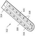
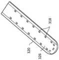
具体地,所述远侧端部组件包括一对夹爪,所述一对夹爪能够相对于彼此移动以打开和闭合所述一对夹爪的相对的内表面之间的间隙,所述一对夹爪包括被布置成将所述EM能量(例如,微波EM能量)发射到所述相对的内表面之间的所述间隙中的能量递送结构,其中所述能量递送结构包括安装在所述一对夹爪中的一者或两者的所述内表面上的微带天线。Specifically, the distal end assembly includes a pair of jaws movable relative to each other to open and close a gap between opposing inner surfaces of the pair of jaws, the one The pair of jaws includes an energy delivery structure arranged to emit said EM energy (eg, microwave EM energy) into said gap between said opposing inner surfaces, wherein said energy delivery structure includes an energy delivery structure mounted on said a microstrip antenna on said inner surface of one or both of the pair of jaws.
所述能量递送结构可被布置成将所发射的微波场基本上局限于所述一对夹爪之间的区域内。因此,所述一对夹爪中的所述能量递送结构操作来为被夹持在所述夹爪之间的生物血管提供局部血管密封。The energy delivery structure may be arranged to substantially confine the emitted microwave field to an area between the pair of jaws. Accordingly, the energy delivery structure in the pair of jaws operates to provide a localized vascular seal for a biological vessel clamped between the jaws.
所述远侧端部组件可包括刀片,所述刀片包括所述换能器以切断生物组织,所述刀片可滑动地设置在所述远侧端部组件内以便能够移动通过所述一对夹爪之间的所述区域。以此方式,所述刀片可操作来切断由所述能量递送结构形成的局部血管密封并且分割血管。所述换能器可连接到所述刀片的近侧端部部分。The distal tip assembly may include a blade including the transducer to sever biological tissue, the blade being slidably disposed within the distal tip assembly so as to be movable through the pair of jaws The area between the claws. In this manner, the blade is operable to sever the local vascular seal formed by the energy delivery structure and segment the blood vessel. The transducer is connectable to a proximal end portion of the blade.
另外,代替形成刀片的一部分,所述磁致伸缩换能器可容纳在所述夹爪中的一者之中或之上。例如,所述一对夹爪可包括:第一(例如,有源)夹爪,所述第一夹爪具有安装在其中的所述能量递送结构;以及第二(例如,无源)夹爪,所述第二夹爪不接收EM能量(例如,RF或微波EM能量)馈送,并且其中所述换能器容纳在所述第二夹爪之中或之上。可替代地,所述换能器可在所述第一夹爪的体积内或者所述第一夹爪的表面上。例如,所述换能器可被并入到所述微带天线中。具体地,所述微带天线可为共面微带天线,所述共面微带天线包括:平面介电衬底,所述平面介电衬底具有在所述相对的内表面之间的所述间隙处暴露的顶表面,以及在所述平面介电衬底的与所述顶表面相对的一侧上的下表面;接地导体层,所述接地导体层在所述下表面上;接地导电带,所述接地导电带在所述顶表面上并且电连接到所述接地导体层;以及在所述顶表面上的有源导电带,所述有源导电带与所述接地导电带间隔开,其中所述有源导电带和所述接地导电带被定位成在所述一对夹爪之间的所述区域内具有一致的最近间距,并且其中所述换能器定位在所述平面介电衬底的所述顶表面上并且定位在所述有源导电带与所述接地导电带之间。在一个实施方案中,多个磁致伸缩换能器可定位在所述有源导电带与所述接地导电带之间。以此方式,由定位在所述有源导电带与所述接地导电带之间的多个较小的换能器提供的组合的超声振动可与定位在夹爪之中或之上(例如,所述夹爪的体积内)的较大的单个换能器较为相当。Additionally, instead of forming part of the blade, the magnetostrictive transducer may be housed in or on one of the jaws. For example, the pair of jaws may include: a first (eg, active) jaw having the energy delivery structure mounted therein; and a second (eg, passive) jaw , the second jaw does not receive a feed of EM energy (eg, RF or microwave EM energy), and wherein the transducer is housed in or on the second jaw. Alternatively, the transducer may be within the volume of the first jaw or on a surface of the first jaw. For example, the transducer may be incorporated into the microstrip antenna. Specifically, the microstrip antenna may be a coplanar microstrip antenna, and the coplanar microstrip antenna includes: a planar dielectric substrate having the a top surface exposed at the gap, and a lower surface on the side of the planar dielectric substrate opposite to the top surface; a ground conductor layer on the lower surface; a ground conductive a ground conductive strip on the top surface and electrically connected to the ground conductor layer; and an active conductive strip on the top surface spaced apart from the ground conductive strip , wherein the active conductive strip and the ground conductive strip are positioned with a consistent closest spacing in the region between the pair of jaws, and wherein the transducer is positioned between the planar on the top surface of the electrical substrate and positioned between the active conductive strap and the grounded conductive strap. In one implementation, a plurality of magnetostrictive transducers may be positioned between the active conductive strip and the grounded conductive strip. In this way, the combined ultrasonic vibrations provided by multiple smaller transducers positioned between the active conductive strip and the grounded conductive strip can be compared to those positioned in or on the jaws (e.g., Larger individual transducers within the volume of the jaw) are comparable.
在所述换能器容纳在所述夹爪中的一者之中或之上的情况下,可能不提供刀片。然而,可替代地,此外还可能存在刀片,但刀片可为超声换能器提供不同类型的切割机构,例如,刀片可包括具有适于对生物组织进行切片的锋利边缘的刚性元件,例如外科手术刀型刀片等。Where the transducer is housed in or on one of the jaws, no blade may be provided. Alternatively, however, there may also be a blade in addition, but the blade may provide a different type of cutting mechanism for the ultrasonic transducer, for example, the blade may comprise a rigid element with a sharp edge suitable for slicing biological tissue, such as a surgical Knife blades etc.
在使用中,血管密封器因此可执行血管密封和血管分割。血管密封通常是施加压力来将生物血管的壁挤压在一起,之后施加某种形式的热能量。热能量通过使用微波EM能量对被夹持的组织进行介电加热来施加。所施加的机电能量破坏组织细胞/使所述组织细胞变性,并且形成主要存在于血管壁中的胶原蛋白的混合物,这能有效地将血管壁粘结在一起。随着时间的推移,进行术后细胞修复和再生以进一步加强密封。血管分割是切断连续的生物血管以将其分为两个片块的过程。这通常在第一次密封血管之后执行。血管分割由磁致伸缩换能器执行,所述磁致伸缩换能器可为夹爪之间的刀片的一部分或者可容纳在夹爪中的一者之中或之上。In use, the vessel sealer can thus perform vessel sealing and vessel segmentation. Vascular sealing typically applies pressure to squeeze the walls of a biological blood vessel together, followed by some form of thermal energy. Thermal energy is applied by dielectric heating of the clamped tissue using microwave EM energy. The applied electromechanical energy destroys/denatures the tissue cells and forms a mixture of collagen, mainly present in the blood vessel walls, which effectively binds the blood vessel walls together. Over time, post-operative cellular repair and regeneration is performed to further strengthen the seal. Vessel segmentation is the process of severing a continuous biological vessel to divide it into two pieces. This is usually performed after the vessel has been sealed for the first time. Vessel segmentation is performed by a magnetostrictive transducer, which may be part of a blade between the jaws or may be housed in or on one of the jaws.
所述能量递送结构可包括设置在所述一对夹爪中的一者或两者的所述内表面上的微波辐射器元件。例如,所述一对夹爪可包括:有源夹爪,所述有源夹爪具有安装在其中的所述能量递送结构;以及无源夹爪,所述无源夹爪不接收微波EM能量馈送。可替代地,所述一对夹爪中的每个夹爪可在其中安装有相应的能量递送结构。在此场景下,所述远侧端部组件可包括功率分配器,所述功率分配器用于在所述相应的能量递送结构之间分配从所述同轴传输线路接收到的所述微波EM能量。在另一实例中,所述能量递送结构可具有在所述一对夹爪之间分配的部件,使得所述一对夹爪结合来提供微波辐射器元件。The energy delivery structure may include a microwave applicator element disposed on the inner surface of one or both of the pair of jaws. For example, the pair of jaws may include: an active jaw having the energy delivery structure mounted therein; and a passive jaw that does not receive microwave EM energy feed. Alternatively, each jaw of the pair of jaws may have a respective energy delivery structure mounted therein. In this scenario, said distal tip assembly may comprise a power splitter for splitting said microwave EM energy received from said coaxial transmission line between said respective energy delivery structures . In another example, the energy delivery structure may have a component distributed between the pair of jaws such that the pair of jaws combine to provide a microwave applicator element.
所述微波辐射器元件可包括安装在所述一对夹爪中的一者或两者的所述内表面上的共面微带天线。在一个实施方案中,所述共面微带天线可安装在有源夹爪上,并且相对的夹爪可为无源夹爪。所述无源夹爪在所述间隙处的所述内表面可包括可弹性变形的电绝缘材料(例如,硅酮橡胶等)层。所述电绝缘材料层可提供隔热层以抑制热量传播到所述夹爪之外。在一些情况下,可变形层可协助沿着所述一对夹爪的长度提供基本上恒定的夹紧力。The microwave applicator element may comprise a coplanar microstrip antenna mounted on the inner surface of one or both of the pair of jaws. In one embodiment, the coplanar microstrip antenna may be mounted on an active jaw, and the opposing jaw may be a passive jaw. The inner surface of the passive jaw at the gap may comprise an elastically deformable layer of electrically insulating material (eg, silicone rubber, etc.). The layer of electrically insulating material may provide a thermal barrier to inhibit heat from spreading out of the jaws. In some cases, the deformable layer can assist in providing a substantially constant clamping force along the length of the pair of jaws.
所述共面微带天线可包括平面介电衬底,所述平面介电衬底具有在所述相对的内表面之间的所述间隙处暴露的顶表面,以及在所述平面介电衬底的与所述顶表面相对的一侧上的下表面。所述介电衬底可由合适的陶瓷制成。所述介电衬底可安装,例如粘结或以其他方式附连到所述有源夹爪。接地导体层可设于所述下表面上。这可为金属化层,例如铜层、银层、金层等。在所述介电衬底的所述顶表面上,可设有电连接到所述接地导体层的接地导电带,以及与所述接地导电带间隔开的有源导电带。接地导体可电连接到所述同轴传输线路的外导体。所述有源导电带可连接到所述同轴传输线路的内导体。所述有源导电带和所述接地导电带可被定位成在所述一对夹爪之间的所述区域内具有一致的最近间距。当所发射的微波场将达到其最强状态时,所述有源导电带与所述接地导电带之间的所述最近间距是所述区域。因此,可为所述有源导电带和所述接地导电带选择将场局限于所述夹爪之间的所述区域内的几何形状。The coplanar microstrip antenna may include a planar dielectric substrate having a top surface exposed at the gap between the opposed inner surfaces, and A lower surface of the bottom on the side opposite the top surface. The dielectric substrate can be made of a suitable ceramic. The dielectric substrate may be mounted, eg, glued or otherwise attached, to the active jaw. A ground conductor layer may be provided on the lower surface. This may be a metallization layer such as a copper layer, silver layer, gold layer or the like. On the top surface of the dielectric substrate, there may be provided a ground conductive strap electrically connected to the ground conductor layer, and an active conductive strap spaced apart from the ground conductive strap. A ground conductor may be electrically connected to the outer conductor of the coaxial transmission line. The active conductive strip is connectable to the inner conductor of the coaxial transmission line. The active conductive strip and the ground conductive strip may be positioned with a consistent closest spacing in the region between the pair of jaws. The closest spacing between the active conductive strip and the ground conductive strip is the region when the emitted microwave field will be at its strongest state. Thus, a geometry may be chosen for the active conductive strip and the ground conductive strip that confines the field to the area between the jaws.
在一个实例中,所述有源导电带可为细长的纵向延伸的指状电极。所述接地导电带包括侧接所述指状电极的一个或多个细长部分,由此所述最近间距包括沿着所述一对夹爪的所述内表面的纵向延伸的细长部分。所述接地导电带可侧接于所述指状电极的两侧。在一个实例中,所述接地导电带可为侧接于所述指状电极的两侧并包围所述指状电极的远侧端部的U形元件。在此实例中,所述场可主要被局限于位于所述U形元件内侧的区域。在一个或多个磁致伸缩超声换能器定位在所述共面微带天线中的情况下,所述超声换能器可定位在所述指状电极与U形元件之间的间隙中。In one example, the active conductive strips may be elongated longitudinally extending finger electrodes. The ground strap includes one or more elongated portions flanking the finger electrodes, whereby the closest spacing includes an elongated portion extending longitudinally along the inner surface of the pair of jaws. The grounding conductive strip may be laterally connected to two sides of the finger electrode. In one example, the ground conductive strap may be a U-shaped element flanking both sides of the finger electrodes and surrounding the distal ends of the finger electrodes. In this example, the field may be mainly confined to the area located inside the U-shaped element. Where one or more magnetostrictive ultrasound transducers are positioned in the coplanar microstrip antenna, the ultrasound transducers may be positioned in the gap between the finger electrodes and the U-shaped element.
所述接地导电带可经由形成于所述介电衬底中的通孔而电连接到所述接地导体层。The ground conductive strips may be electrically connected to the ground conductor layer via vias formed in the dielectric substrate.
所述微波辐射器元件不需要限制于共面微带配置。在其他实例中,所述微波辐射器元件可包括行波天线、或者曲折或梳状的微带布置。The microwave applicator elements need not be limited to coplanar microstrip configurations. In other examples, the microwave applicator element may comprise a traveling wave antenna, or a meander or comb-like microstrip arrangement.
所述一对夹爪的所述相对的内表面可包括纹理化或脊状部分以将生物组织保持在所述间隙内。此特征还可准许密封界面处因变性过程而产生的气体或蒸气逸出。The opposing inner surfaces of the pair of jaws may include textured or ridged portions to retain biological tissue within the gap. This feature may also permit the escape of gases or vapors generated at the seal interface due to the denaturation process.
所述一对夹爪可能够相对于彼此围绕横向于所述同轴传输线路的纵向轴线的铰链轴线枢转。在一个实例中,所述一对夹爪包括:静止夹爪,所述静止夹爪相对于所述器械轴固定;以及可移动夹爪,所述可移动夹爪相对于所述静止夹爪可枢转地安装以打开和闭合所述相对的内表面之间的所述间隙。所述能量递送结构可设置在所述静止夹爪的所述内表面上。在另一个实例中,例如在对称的夹钳型布置中,两个夹爪被布置成相对于所述器械轴枢转。所述一对夹爪的相对移动可从所述器械轴的近侧端部处的手柄进行控制。控制杆或控制线可穿过所述器械轴以将所述手柄上的致动机构可操作地联接到所述一对夹爪。The pair of jaws may be pivotable relative to each other about a hinge axis transverse to the longitudinal axis of the coaxial transmission line. In one example, the pair of jaws includes: a stationary jaw fixed relative to the instrument shaft; and a movable jaw movable relative to the stationary jaw. Pivotally mounted to open and close said gap between said opposed inner surfaces. The energy delivery structure may be disposed on the inner surface of the stationary jaw. In another example, for example in a symmetrical clamp-type arrangement, both jaws are arranged to pivot relative to the instrument shaft. Relative movement of the pair of jaws is controllable from a handle at the proximal end of the instrument shaft. A control rod or control wire may pass through the instrument shaft to operably couple an actuation mechanism on the handle to the pair of jaws.
在另一个实例中,所述一对夹爪可被布置成以将其内表面维持在对准(例如,平行)取向上的方式相对于彼此移动。这种配置对于沿着夹爪的长度在所抓取的组织上维持均匀的压力而言可能是期望的。WO 2015/097472中公开了这种闭合机构的一个实例。In another example, the pair of jaws may be arranged to move relative to each other in a manner to maintain their inner surfaces in an aligned (eg parallel) orientation. This configuration may be desirable to maintain uniform pressure on the grasped tissue along the length of the jaws. An example of such a closure mechanism is disclosed in WO 2015/097472.
当存在时,所述刀片可能够在纵向方向上在缩回位置与伸展位置之间滑动,在所述缩回位置,所述刀片位于所述一对夹爪的近侧,在伸展位置,所述刀片位于所述一对夹爪之间的所述区域内。当夹爪处于组织夹持配置,即至少部分地闭合时,期望所述刀片滑动到所述夹爪之间的所述区域中。所述刀片可能够沿着形成于所述一对夹爪中(即,所述一对夹爪中的每个夹爪中)的纵向延伸的凹槽滑动,使得当所述一对夹爪闭合时,所述刀片可接触保持在所述间隙中的组织。所述槽可被布置成充当切割刀片的导轨,这在所述一对夹爪朝向其远侧端部弯曲的情况下可能是特别有用的。When present, the blade may be slidable in a longitudinal direction between a retracted position in which the blade is proximal to the pair of jaws and an extended position in which the The blade is located in the region between the pair of jaws. When the jaws are in the tissue-gripping configuration, ie at least partially closed, it is desirable for the blade to slide into the region between the jaws. The blade may be slidable along a longitudinally extending groove formed in the pair of jaws (i.e., in each of the pair of jaws) such that when the pair of jaws are closed , the blade may contact tissue held in the gap. The slot may be arranged to act as a guide for the cutting blade, which may be particularly useful if the pair of jaws are bent towards their distal ends.
在另一个实例中,所述刀片可安装在所述一对夹爪中的一者内,并且可能够在横向方向上在缩回位置与伸展位置之间滑动或可以其他方式移动,在所述缩回位置,所述刀片位于所述夹爪的所述内表面下方,在伸展位置,所述刀片位于所述一对夹爪之间的所述区域内。In another example, the blade may be mounted within one of the pair of jaws and may be slidable or otherwise movable in a lateral direction between a retracted position and an extended position, in which In the retracted position, the blade is located below the inner surface of the jaws, and in the extended position, the blade is located in the region between the pair of jaws.
如上文所提及,所述刀片可包括具有适于对生物组织进行切片的锋利边缘的刚性元件,例如外科手术刀型刀片等。这种类型的刀片被配置为执行“冷”切割,这可能是优选的,因为所述刀片具有与其他切割技术相关联的低风险的附带热损坏。然而,本发明不需要限制于冷切割刀片。在其他实例中,所述刀片可包括磁致伸缩换能器、双极射频切割元件和可加热线元件。在所述磁致伸缩换能器不是所述刀片的一部分的情况下,所述磁致伸缩换能器定位在所述血管密封器中的其他位置(例如,定位在所述夹爪中的一者中)以便提供超声切割功能。As mentioned above, the blade may comprise a rigid element having a sharp edge suitable for slicing biological tissue, such as a scalpel type blade or the like. This type of blade is configured to perform "cold" cutting, which may be preferred because the blade has a low risk of incidental heat damage associated with other cutting techniques. However, the invention need not be limited to cold cutting blades. In other examples, the blade may include a magnetostrictive transducer, a bipolar radio frequency cutting element, and a heatable wire element. Where the magnetostrictive transducer is not part of the blade, the magnetostrictive transducer is positioned elsewhere in the vessel sealer (e.g., in one of the jaws). In order to provide ultrasonic cutting function.
如上文所提及,除了其主要的基于微波的血管密封功能和基于超声的分割功能之外,所述血管密封器还可有利地提供辅助功能。例如,所述器械轴可被布置成传送RF EM能量并且所述远侧端部组件可被布置成从所述器械轴接收所述RF EM能量。在此实例中,所述远侧端部组件还可包括被布置成递送所述RF EM能量以切断生物组织的剥离器元件,其中所述剥离器元件位于所述一对夹爪之间的所述区域之外。As mentioned above, the vessel sealer may advantageously provide secondary functions in addition to its primary microwave-based vessel sealing and ultrasound-based segmentation functions. For example, the instrument shaft may be arranged to transmit RF EM energy and the distal tip assembly may be arranged to receive the RF EM energy from the instrument shaft. In this example, the distal tip assembly may further include a stripper element arranged to deliver the RF EM energy to sever biological tissue, wherein the stripper element is positioned between the pair of jaws on all sides. outside the above area.
所述剥离器元件可包括具有有源电极和返回电极的双极RF结构。所述有源电极(切割元件)可比所述返回电极小一个数量级。所述返回电极可形成于与所述剥离器元件相邻的夹爪的外表面上,使得当在脱水术野中使用时,所述返回电极与组织直接接触。所述剥离器元件因此可用于小范围或精细切割,例如以改进对治疗部位的触及或打开所述治疗部位。The stripper element may comprise a bipolar RF structure having an active electrode and a return electrode. The active electrode (cutting element) may be an order of magnitude smaller than the return electrode. The return electrode may be formed on an outer surface of the jaw adjacent the stripper element such that when used in a dehydration field, the return electrode is in direct contact with tissue. The stripper element may thus be used for small or fine cuts, for example to improve access to or open up a treatment site.
切割区域可安设于远离(即,突出于)所述一对夹爪处。例如,所述剥离器元件可包括呈现出用于接触组织的前导边缘的突出主体。所述有源电极可设于所述前导边缘处,例如以确保RF电流密度集中于该区域中。The cutting region may be located away from (ie, protrude from) the pair of jaws. For example, the stripper element may comprise a protruding body presenting a leading edge for contacting tissue. The active electrode may be provided at the leading edge, for example to ensure that RF current density is concentrated in this area.
所述剥离器元件可安装在所述一对夹爪的外表面上。例如,所述突出主体可在所述一对夹爪的远侧表面或侧表面上。所述突出主体可由合适的电介质形成,其中所述有源电极是在上面制作的导电部分。所述返回电极可在所述突出主体上或在所述一对夹爪的所述外表面上。The stripper element may be mounted on an outer surface of the pair of jaws. For example, the protruding body may be on a distal or side surface of the pair of jaws. The protruding body may be formed from a suitable dielectric on which the active electrode is a conductive part fabricated. The return electrode may be on the protruding body or on the outer surface of the pair of jaws.
在另一个实例中,所述剥离器元件可安装在纵向延伸器上,所述纵向延伸器可相对于所述一对夹爪纵向地移动。这种布置可有助于所述剥离器元件在使用中的可见度,例如通过使得所述剥离器元件能够在所述一对夹爪之前移动到治疗部位中来实现。In another example, the stripper element may be mounted on a longitudinal extender that is longitudinally movable relative to the pair of jaws. Such an arrangement may facilitate visibility of the stripper element in use, for example by enabling movement of the stripper element into the treatment site ahead of the pair of jaws.
在优选实例中,所述剥离器元件可安装在所述远侧端部组件的远侧端部处。In a preferred example, the stripper element is mountable at the distal end of the distal end assembly.
所述微波EM能量和所述RF EM能量可沿着穿过所述器械轴的共用信号通路传送。例如,同轴传输线路可提供用于传送所述微波EM能量和所述RF EM能量两者的共用信号通路。在此布置中,所述远侧端部组件可包括用于将所述微波EM能量阻挡于所述剥离器元件的电感式滤波器,以及用于将所述RF EM能量阻挡于所述一对夹爪上的所述能量递送结构的电容式滤波器。在替代布置中,所述RF EM能量和所述微波EM能量沿着所述器械轴内的单独的通路传送,其中所述电感式滤波器和所述电容式滤波器设于所述器械轴的近侧端部处,例如设于手柄中。The microwave EM energy and the RF EM energy may be transmitted along a common signal path through the instrument axis. For example, a coaxial transmission line may provide a common signal path for carrying both the microwave EM energy and the RF EM energy. In this arrangement, the distal tip assembly may include an inductive filter for blocking the microwave EM energy to the stripper element, and for blocking the RF EM energy to the pair of Capacitive filter of the energy delivery structure on the jaws. In an alternative arrangement, the RF EM energy and the microwave EM energy are delivered along separate pathways within the instrument shaft, wherein the inductive filter and the capacitive filter are provided on the instrument shaft At the proximal end, eg in the handle.
如上文所提及,所述远侧端部组件和所述器械轴可被设定尺寸以装配在外科观测装置的器械通道内。所述外科观测装置可为腹腔镜或内窥镜。外科观测装置通常设有插入管,所述插入管是在侵入性手术期间引入到患者的身体内的刚性或柔性(例如,可转向)导管。所述插入管可包括器械通道和光学通道(例如,用于传递光以照亮在插入管的远侧端部处的治疗部位和/或捕获所述治疗部位的图像)。所述器械通道可具有适合于接纳侵入性外科工具的直径。所述器械通道的所述直径可等于或小于13mm、优选地等于或小于10mm、以及更优选地(尤其是对于柔性插入管)等于或小于5mm。As mentioned above, the distal end assembly and the instrument shaft may be sized to fit within an instrument channel of a surgical scope. The surgical observation device may be a laparoscope or an endoscope. Surgical scopes are typically provided with an insertion tube, which is a rigid or flexible (eg, steerable) catheter that is introduced into a patient's body during an invasive procedure. The insertion tube may include an instrument channel and an optical channel (eg, for delivering light to illuminate and/or capture an image of the treatment site at the distal end of the insertion tube). The instrument channel may have a diameter suitable for receiving an invasive surgical tool. The diameter of the instrument channel may be equal to or smaller than 13 mm, preferably equal to or smaller than 10 mm, and more preferably (especially for flexible insertion tubes) equal to or smaller than 5 mm.
上文讨论的所述血管密封器可应用于其他组织焊接技术中。例如,所述能量递送结构可用作吻合钉的替代方案。在一些腹部手术中,吻合钉枪用于递送50至100个小的吻合钉,所述吻合钉在长度可为70mm或更大的夹爪之间同时击发,或者从直径为20至50mm的环形夹爪布置同时击发。在这种类型的应用中,多个天线结构(诸如本文所讨论的那些)可用于覆盖所需的长度。所述天线结构可以任何数量的阵列形式布置成以合适的方式同时地、顺序地或逐渐地激活。The vessel sealers discussed above can be applied in other tissue welding techniques. For example, the energy delivery structure can be used as a replacement for staples. In some abdominal procedures, staple guns are used to deliver 50 to 100 small staples that are fired simultaneously between jaws that can be 70mm in length or more, or from a ring with a diameter of 20 to 50mm The jaw arrangement fires simultaneously. In this type of application, multiple antenna structures, such as those discussed herein, can be used to cover the required length. The antenna structures may be arranged in any number of arrays to be activated simultaneously, sequentially or gradually in a suitable manner.
本发明的第二方面提供了一种电外科发生器,所述电外科发生器包括:电磁(EM)信号供应单元,所述EM信号供应单元用于产生EM能量;电信号供应单元,所述电信号供应单元用于产生电信号来驱动磁致伸缩超声换能器(例如,以产生超声振动);输出端口,所述输出端口被配置为可连接到电外科器械以从所述电外科器械的远侧端部递送所述EM能量,并且使用所述电信号来产生超声振动;以及馈送结构,所述馈送结构用于将所述EM能量从所述EM信号供应单元传送到所述输出端口,并且用于将所述电信号从所述电信号供应单元传送到所述输出端口,其中所述馈送结构具有用于将所述EM能量和所述电信号传送到所述输出端口的共用信号通路。A second aspect of the present invention provides an electrosurgical generator comprising: an electromagnetic (EM) signal supply unit for generating EM energy; an electrical signal supply unit, the An electrical signal supply unit for generating an electrical signal to drive the magnetostrictive ultrasonic transducer (for example, to generate ultrasonic vibrations); an output port configured to be connectable to an electrosurgical instrument to receive from the electrosurgical instrument The distal end of the delivery of the EM energy, and using the electrical signal to generate ultrasonic vibration; and a feeding structure, the feeding structure is used to transfer the EM energy from the EM signal supply unit to the output port , and for delivering said electrical signal from said electrical signal supply unit to said output port, wherein said feed structure has a common signal for delivering said EM energy and said electrical signal to said output port path.
在此布置中,同一个发生器可供应RF能量和/或微波能量,例如以实现组织切割、消融、止血或其他效果,并且供应电信号来驱动超声换能器(例如,磁致伸缩换能器)以在组织中产生超声振动。超声振动可用于分割、剥离或切割生物组织。通过将RF能量和/或微波能量并入到同一个发生器中,本发明同样可使得同一个器械能够递送RF能量和/或微波能量。这可在治疗过程期间为执业医师提供更多治疗选择。In this arrangement, the same generator may supply RF energy and/or microwave energy, for example, to effect tissue cutting, ablation, hemostasis, or other effects, and an electrical signal to drive an ultrasound transducer (e.g., a magnetostrictive transducer). device) to generate ultrasonic vibrations in tissue. Ultrasonic vibrations can be used to segment, peel or cut biological tissue. By incorporating RF energy and/or microwave energy into the same generator, the present invention also enables the same instrument to deliver RF energy and/or microwave energy. This may provide the practitioner with more treatment options during the course of treatment.
如上文所提及,所述电信号可为变化或振荡的电流信号。所述变化或振荡的电流信号可具有以下形式中的一者:脉冲、正弦波、方波、梯形波、斜波、指数曲线波。在任何情况下,所述电信号都可被施加到磁致伸缩换能器的所述线圈以在所述换能器的磁致伸缩元件周围引发变化的磁场。由于磁致伸缩效应,所述磁致伸缩元件随着磁场的变化(以及电信号中的电流的变化)而改变其物理尺寸。因此,为了产生超声振动,所述电信号包括处于超声频率(例如,20kHz至5MHz)的振荡(例如,电流振荡)。在一个实施方案中,所述电信号是振荡的电流信号,所述振荡的电流信号的幅度在其最小值与最大值之间(例如,在0A与100A之间)变化高达100A。As mentioned above, the electrical signal may be a varying or oscillating current signal. The varying or oscillating current signal may have one of the following forms: pulse, sine wave, square wave, trapezoidal wave, ramp wave, exponential curve wave. In any event, the electrical signal may be applied to the coil of the magnetostrictive transducer to induce a varying magnetic field around the magnetostrictive element of the transducer. Due to the magnetostrictive effect, the magnetostrictive element changes its physical size in response to changes in the magnetic field (and changes in current in electrical signals). Thus, to generate ultrasonic vibrations, the electrical signal includes oscillations (eg, current oscillations) at ultrasonic frequencies (eg, 20 kHz to 5 MHz). In one embodiment, the electrical signal is an oscillating current signal whose amplitude varies between its minimum and maximum values (eg, between 0A and 100A) up to 100A.
所述EM信号供应单元可被布置成单独地或同时供应RF能量和微波能量两者。例如,所述EM信号供应单元可包括:微波信号发生器,所述微波信号发生器用于产生具有第一频率的微波EM辐射;以及射频(RF)信号发生器,所述RF信号发生器用于产生具有低于所述第一频率的第二频率的RF电磁(EM)辐射。The EM signal supply unit may be arranged to supply both RF energy and microwave energy separately or simultaneously. For example, the EM signal supply unit may include: a microwave signal generator for generating microwave EM radiation having a first frequency; and a radio frequency (RF) signal generator for generating RF electromagnetic (EM) radiation having a second frequency lower than the first frequency.
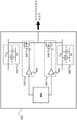
所述馈送结构可包括用于将所述输出端口连接到所述电信号供应单元的电信号通道,以及用于将所述输出端口连接到所述微波信号发生器的微波通道。所述电信号通道和所述微波通道可分别包括始于所述电信号供应单元和所述微波信号发生器的物理上分开的信号通路。所述馈送结构可包括第一组合电路,所述第一组合电路具有:第一输入端,所述第一输入端被连接来从所述电信号通道接收所述电信号;第二输入端,所述第二输入端被连接来从所述微波通道接收所述微波EM辐射;以及输出端,所述输出端与所述第一输入端和所述第二输入端连通以将所述电信号和所述微波EM辐射输送到所述共用信号通路。The feeding structure may comprise an electrical signal channel for connecting the output port to the electrical signal supply unit, and a microwave channel for connecting the output port to the microwave signal generator. The electrical signal channel and the microwave channel may comprise physically separate signal paths from the electrical signal supply unit and the microwave signal generator, respectively. The feed structure may comprise a first combination circuit having a first input connected to receive the electrical signal from the electrical signal path; a second input, the second input connected to receive the microwave EM radiation from the microwave channel; and an output in communication with the first input and the second input to transmit the electrical signal and said microwave EM radiation is delivered to said common signal path.
所述微波通道可包括第一滤波器,所述第一滤波器被布置成准许微波EM辐射从所述微波信号发生器传递到所述第一组合电路,但防止(例如,阻止)所述电信号从所述第一组合电路传递到所述微波信号发生器。在一个实施方案中,所述第一滤波器可为具有相对高的截止频率(例如,约300MHz)的高通滤波器,使得所述第一滤波器使微波频率能量通过,但阻止所述电信号(其具有超声频率)的较低频率和所存在的任何RF信号。例如,可使用1pF电容器。The microwave channel may include a first filter arranged to permit microwave EM radiation to pass from the microwave signal generator to the first combining circuit, but prevent (e.g. block) the electrical A signal is passed from the first combining circuit to the microwave signal generator. In one embodiment, the first filter may be a high pass filter with a relatively high cutoff frequency (e.g., about 300 MHz), such that the first filter passes microwave frequency energy but blocks the electrical signal (which has the ultrasonic frequency) and any RF signals present. For example, a 1pF capacitor can be used.
另外,所述电信号通道可包括第二滤波器,所述第二滤波器被布置成准许所述电信号从所述电信号供应单元传递到所述第一组合电路,但防止(例如,阻止)所述微波EM辐射从所述第一组合电路传递到所述电信号供应单元。在一个实施方案中,所述第二滤波器可为具有相对高的截止频率(例如,约300MHz)的低通滤波器,使得所述第二滤波器使具有超声频率的所述电信号和所存在的任何RF信号通过,但阻止较高频率微波能量。例如,可使用一根或多根(例如,三根)微波短截线,其中短截线被布置成将具有与微波能量相同的频率的信号滤除。Additionally, the electrical signal path may comprise a second filter arranged to permit the electrical signal to pass from the electrical signal supply unit to the first combining circuit, but prevent (eg block ) said microwave EM radiation is delivered from said first combining circuit to said electrical signal supply unit. In one embodiment, the second filter may be a low-pass filter with a relatively high cut-off frequency (e.g., about 300 MHz), such that the second filter allows the electrical signal having an ultrasonic frequency and the Any RF signals present are passed, but higher frequency microwave energy is blocked. For example, one or more (eg, three) microwave stubs may be used, wherein the stubs are arranged to filter out signals having the same frequency as the microwave energy.
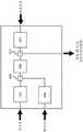
所述馈送结构可包括用于将所述输出端口连接到所述RF信号发生器的RF通道。所述RF通道和所述微波通道可分别包括始于所述RF信号发生器和所述微波信号发生器的物理上分开的信号通路。另外,所述RF通道可与所述电信号通道进行组合。所述馈送结构可包括第二组合电路,所述第二组合电路连接到所述电信号通道并且具有:第一输入端,所述第一输入端被连接来从所述电信号供应单元接收所述电信号;以及第二输入端,所述第二输入端被连接来从所述RF通道接收所述RF EM辐射;以及输出端,所述输出端与所述第一输入端和所述第二输入端连通以将所述RF EM辐射和所述电信号输送到所述第一组合电路。The feed structure may comprise an RF channel for connecting the output port to the RF signal generator. The RF channel and the microwave channel may comprise physically separate signal paths from the RF signal generator and the microwave signal generator, respectively. Additionally, the RF channel may be combined with the electrical signal channel. The feeding structure may comprise a second combining circuit connected to the electrical signal path and having a first input connected to receive the electrical signal from the electrical signal supply unit. said electrical signal; and a second input connected to receive said RF EM radiation from said RF channel; and an output connected to said first input and said first Two inputs communicate to deliver the RF EM radiation and the electrical signal to the first combining circuit.
所述电信号通道可包括第三滤波器,所述第三滤波器被布置成准许所述电信号从所述电信号供应单元传递到所述第二组合电路,但防止(例如,阻止)所述RF EM辐射从所述第二组合电路传递到所述电信号供应单元。在一个实施方案中,所述第三滤波器可为具有相对低的截止频率(例如,约100kHz)的低通滤波器,使得所述第三滤波器使具有超声频率的所述电信号通过,但阻止RF信号。例如,可使用电感器。The electrical signal path may comprise a third filter arranged to permit the electrical signal to pass from the electrical signal supply unit to the second combining circuit but prevent (eg block) all The RF EM radiation is passed from the second combining circuit to the electrical signal supply unit. In one embodiment, the third filter may be a low-pass filter with a relatively low cut-off frequency (e.g., about 100 kHz), such that the third filter passes the electrical signal having an ultrasonic frequency, But blocks RF signals. For example, inductors can be used.
另外,所述RF通道可包括第四滤波器,所述第四滤波器被布置成准许所述RF EM辐射从所述RF信号发生器传递到所述第二组合电路,但防止(例如,阻止)所述电信号从所述第二组合电路传递到所述RF信号发生器。在一个实施方案中,所述第四滤波器可为具有相对低的截止频率(例如,约100kHz)的高通滤波器,使得所述第四滤波器使RF频率能量通过,但阻止所述电信号的较低超声频率。例如,可使用1μF电容器。Additionally, the RF channel may include a fourth filter arranged to permit the RF EM radiation to pass from the RF signal generator to the second combining circuit, but prevent (e.g. block ) the electrical signal is passed from the second combining circuit to the RF signal generator. In one embodiment, the fourth filter may be a high pass filter with a relatively low cutoff frequency (e.g., about 100 kHz), such that the fourth filter passes RF frequency energy but blocks the electrical signal lower ultrasonic frequencies. For example, a 1 μF capacitor can be used.
所述电信号供应单元可包括:第一电源,所述第一电源用于输出第一电源信号;信号源,所述信号源用于输出第一控制信号;第一切换电路,所述第一切换电路具有:控制输入端,所述控制输入端耦合到所述信号源以接收所述第一控制信号;电源输入端,所述电源输入端耦合到所述第一电源以接收所述第一电源信号;以及输出端,其中所述第一切换电路可操作来基于所述第一电源信号和所述第一控制信号而在所述输出端处提供所述电信号的至少一部分。在一个实施方案中,所述第一切换电路包括电流源,所述电流源从(例如,使用)所述第一电源信号并根据所述第一控制信号的特性(例如,振荡、频率、变化)来产生所述电信号(或其一部分)。例如,所述电流源可为电压控制的电流源,诸如IGFET或MOSFET,或电流控制的电流源,诸如BJT。The electrical signal supply unit may include: a first power supply, the first power supply is used to output a first power supply signal; a signal source, the signal source is used to output a first control signal; a first switching circuit, the first The switching circuit has a control input coupled to the signal source to receive the first control signal; a power input coupled to the first power supply to receive the first a power supply signal; and an output, wherein the first switching circuit is operable to provide at least a portion of the electrical signal at the output based on the first power supply signal and the first control signal. In one embodiment, the first switching circuit includes a current source derived from (eg, using) the first power supply signal and based on characteristics (eg, oscillation, frequency, variation) of the first control signal ) to generate the electrical signal (or a portion thereof). For example, the current source may be a voltage controlled current source, such as an IGFET or MOSFET, or a current controlled current source, such as a BJT.
所述第一电源可为DC电源。另外,所述信号源提供变化的控制或触发信号,所述控制或触发信号用于控制从(例如,使用)所述第一电源信号产生所述电信号。所述信号源可为微控制器(例如,ArduinoTM微控制器)、Colpitts振荡器、Hartley振荡器或555计时器。在一个实施方案中,所述第一控制信号具有振荡波形,诸如脉冲、正弦波、方波、梯形波、斜波、或指数曲线波形。在一个实例中,所述第一控制信号可以超声频率(例如,20kHz至5MHz)在低状态(例如,0V)与高状态(例如,5V)之间振荡。所述第一切换电路通过从所述第一电源信号产生振荡的电(例如,电流)信号并具有所述第一控制信号的振荡来产生所述电信号(或其一部分)。例如,当所述第一控制信号为低时,所述第一切换电路处于关断状态,使得没有电信号从所述电信号供应单元输出。然而,当所述第一控制信号为高时,所述第一切换电路处于接通状态,使得从所述电信号供应单元输出电(例如,电流)信号。这种输出电(例如,电流)信号可由所述第一切换电路的所述电流源从所述第一电源信号产生。这种输出电(例如,电流)信号可传输到第一方面的电外科器械,并且用于驱动其磁致伸缩换能器,以便在所述器械的所述远侧端部周围产生超声振动来治疗(例如,分割、切割)生物组织。The first power source may be a DC power source. Additionally, the signal source provides a varying control or trigger signal for controlling generation of the electrical signal from (eg using) the first power supply signal. The signal source can be a microcontroller (eg, an Arduino™ microcontroller), a Colpitts oscillator, a Hartley oscillator, or a 555 timer. In one embodiment, the first control signal has an oscillating waveform, such as a pulse, sine, square, trapezoidal, ramp, or exponential waveform. In one example, the first control signal can oscillate between a low state (eg, 0V) and a high state (eg, 5V) at an ultrasonic frequency (eg, 20 kHz to 5 MHz). The first switching circuit generates the electrical signal (or a portion thereof) by generating an oscillating electrical (eg, current) signal from the first power supply signal and having oscillation of the first control signal. For example, when the first control signal is low, the first switching circuit is in an off state, so that no electrical signal is output from the electrical signal supply unit. However, when the first control signal is high, the first switching circuit is in an on state so that an electric (eg, current) signal is output from the electric signal supply unit. Such an output electrical (eg current) signal may be generated by the current source of the first switching circuit from the first power supply signal. This output electrical (eg current) signal may be transmitted to the electrosurgical instrument of the first aspect and used to drive its magnetostrictive transducer to generate ultrasonic vibrations around said distal end of said instrument to Treating (eg, dividing, cutting) biological tissue.
在以上实例中,所述第一控制信号控制所述第一切换电路以从(例如,使用)所述第一电源信号产生电(例如,电流)信号。取决于所述第一切换电路和所述第一电源的构造,这种电信号可为正或为负。例如,在所述第一电源是以正向配置连接的DC电源并且所述第一切换电路包括P通道MOSFET的情况下,所述输出电流信号是正振荡信号。另一方面,在所述第一电源是以反向配置连接的DC电源并且所述第一切换电路包括N通道MOSFET的情况下,所述输出电流信号是负振荡信号。因此,所述信号源与所述第一电源和所述第一切换电路一起产生完整的电(例如,电流)信号,所述电信号可为正振荡电流信号或负振荡电流信号。In the above example, the first control signal controls the first switching circuit to generate an electrical (eg, current) signal from (eg, using) the first power supply signal. Depending on the configuration of the first switching circuit and the first power supply, this electrical signal may be positive or negative. For example, in case the first power supply is a DC power supply connected in a forward configuration and the first switching circuit comprises a P-channel MOSFET, the output current signal is a positive oscillating signal. On the other hand, in the case where the first power supply is a DC power supply connected in a reverse configuration and the first switching circuit includes an N-channel MOSFET, the output current signal is a negative oscillation signal. Thus, the signal source together with the first power supply and the first switching circuit generates a complete electrical (eg, current) signal, which may be a positive oscillating current signal or a negative oscillating current signal.
然而,在另一个实施方案中,可提供第二电源以用于输出第二电源信号。在这种情况下,像先前一样,所述信号源可被布置成向所述第一切换电路输出所述第一控制信号,但这一次还输出第二控制信号来驱动第二切换电路。所述第一控制信号和所述第二控制信号可彼此具有相差(例如,180度),使得当所述第一控制信号处于最大值(例如,5V)时,所述第二控制信号处于最小值(例如,0V),并且当所述第一控制信号处于最小值(例如,0V)时,所述第二控制信号处于最大值(例如,-5V)。以此方式,所述信号源、所述第一电源和所述第一切换电路可提供所述电信号的一部分(例如,一半或正一半)(例如,在正最大电流与零之间变化),并且所述信号源、所述第二电源和所述第二切换电路可提供所述电信号的第二(或其余)部分(例如,另一半或负一半)(例如,在零与负最大电流之间变化)。因此,有可能产生具有较宽的幅度范围(例如,电流范围)的复合电(例如,电流)信号,所述复合电信号进而可用于产生更强的超声振动。此外,由于所述电信号的两个部分由所述第一控制信号和所述第二控制信号分开控制,因此有可能在所述第一部分与所述第二部分之间引入延时,这可用于确保所述磁致伸缩换能器的所述线圈有时间在循环之间冷却。以此方式,可减少对所述磁致伸缩换能器的磨损和损坏。However, in another embodiment, a second power supply may be provided for outputting the second power supply signal. In this case, as before, the signal source may be arranged to output the first control signal to the first switching circuit, but this time also output a second control signal to drive the second switching circuit. The first control signal and the second control signal may have a phase difference (eg, 180 degrees) from each other such that when the first control signal is at a maximum value (eg, 5V), the second control signal is at a minimum value (eg, 0V), and when the first control signal is at a minimum value (eg, 0V), the second control signal is at a maximum value (eg, -5V). In this way, the signal source, the first power supply, and the first switching circuit may provide a fraction (eg, half or positive half) of the electrical signal (eg, varying between a positive maximum current and zero) , and the signal source, the second power supply, and the second switching circuit may provide a second (or remaining) portion (eg, the other half or the negative half) of the electrical signal (eg, between zero and the negative maximum change between currents). Thus, it is possible to generate a composite electrical (eg, current) signal with a wider amplitude range (eg, current range), which in turn can be used to generate stronger ultrasonic vibrations. Furthermore, since the two parts of the electrical signal are controlled separately by the first control signal and the second control signal, it is possible to introduce a time delay between the first part and the second part, which can be used This is to ensure that the coils of the magnetostrictive transducer have time to cool down between cycles. In this way, wear and damage to the magnetostrictive transducer can be reduced.
应理解,在所述电信号供应单元包括用于提供所述电信号的所述第一部分的所述第一电源和所述第一切换电路,以及用于提供所述电信号的所述第二(或其余)部分的所述第二电源和所述第二切换电路的情况下,所述电信号供应单元还包括连接到所述第一切换电路和所述第二切换电路两者的输出端的共用信号通路,以便将所述第一部分和所述第二部分进行组合并且形成所述电信号来驱动所述磁致伸缩超声换能器。It should be understood that the electrical signal supply unit includes the first power supply and the first switching circuit for providing the first part of the electrical signal, and the second power supply for providing the electrical signal In the case of the second power supply and the second switching circuit of the (or other) part, the electrical signal supply unit further includes an output terminal connected to both the first switching circuit and the second switching circuit A signal path is shared to combine the first portion and the second portion and form the electrical signal to drive the magnetostrictive ultrasound transducer.
在一个实施方案中,所述第一电源和/或所述第二电源包括用于阻止在其输出端处接收交流电流信号或尖峰的滤波电路。此类交流电流或尖峰可能在发生器中的其他位置产生并且可另外在电源的输出端处进入所述电源并对电源造成损坏。因此,所述滤波电路操作来保护电源免受这种损坏。在一个实施方案中,所述滤波电路包括电容电路,例如连接在电源输出端与零伏之间的两个并联的电容器。这种结构的额外优点是,电容电路存储来自电源输出端的电力,使得电力从电容电路,而不是直接从电源递送到电路的其余部分。这种电容电路用于增加可供切换电路用来产生用于驱动磁致伸缩超声换能器的电(例如,电流)信号的电流。In one embodiment, said first power supply and/or said second power supply comprises a filter circuit for preventing reception of alternating current signals or spikes at its output. Such alternating currents or spikes may be generated elsewhere in the generator and may otherwise enter the power supply at its output and cause damage to the power supply. Therefore, the filtering circuit operates to protect the power supply from such damage. In one embodiment, the filtering circuit comprises a capacitive circuit, for example two capacitors connected in parallel between the output of the power supply and zero volts. An additional advantage of this configuration is that the capacitive circuit stores power from the output of the power supply so that power is delivered from the capacitive circuit rather than directly from the power supply to the rest of the circuit. Such a capacitive circuit is used to increase the current available to the switching circuit to generate an electrical (eg, current) signal for driving the magnetostrictive ultrasound transducer.
在一个实施方案中,所述第一切换电路和/或所述第二切换电路包括耦合到开关的信号调节器。所述信号调节器可操作来将控制信号转换成用于操作所述开关的驱动信号。也就是说,来自信号源的输出端的电流和/或电压可能没有大到足以对开关(例如,MOSFET)的固有电容进行充电,以便以超声频率激活开关。因此,所述信号调节器将来自信号源的控制信号放大,使得所述控制信号具有合适大小的电流和/或电压来驱动开关。应注意,所述信号调节器并未改变控制信号的频率,因为频率由信号源专门设定,以便经由磁致伸缩换能器产生所需的超声振动。在一个实施方案中,所述开关是可切换电流源,诸如电压控制的电流源(例如,MOSFET或IGFET)或电流控制的电流源(例如,BJT)。也就是说,所述开关可包括切换电路的前述电流源。In one embodiment, the first switching circuit and/or the second switching circuit includes a signal conditioner coupled to a switch. The signal conditioner is operable to convert the control signal into a drive signal for operating the switch. That is, the current and/or voltage from the output of the signal source may not be large enough to charge the inherent capacitance of the switch (eg, MOSFET) to activate the switch at ultrasonic frequencies. Thus, the signal conditioner amplifies the control signal from the signal source such that the control signal has a suitable magnitude of current and/or voltage to drive the switch. It should be noted that the signal conditioner does not change the frequency of the control signal, as the frequency is specifically set by the signal source in order to generate the desired ultrasonic vibrations via the magnetostrictive transducer. In one embodiment, the switch is a switchable current source, such as a voltage controlled current source (eg, MOSFET or IGFET) or a current controlled current source (eg, BJT). That is, the switch may comprise the aforementioned current source of the switching circuit.
应理解,第一电源可具有与第二电源相同的物理构造,但与第二电源相比较,第一电源可以相反(例如,反向)配置连接。另外,第一切换电路可具有与第二切换电路相同的物理构造,但与第二切换电路(例如,N通道,而不是P通道,反之亦然)相比较,第一切换电路可包括相反类型的开关(例如,MOSFET)。It should be understood that the first power supply may have the same physical configuration as the second power supply, but the first power supply may be connected in an opposite (eg, reverse) configuration compared to the second power supply. Additionally, the first switching circuit may have the same physical configuration as the second switching circuit, but may include the opposite type of switches (for example, MOSFETs).
根据本发明的第三方面,提供了一种电外科设备,所述电外科设备包括:根据第一方面的电外科器械,以及根据第二方面的电外科发生器,其中所述电外科发生器的所述输出端口被配置为可连接到所述电外科器械的所述器械轴的近侧端部。以此方式,由所述发生器产生的所述EM能量(例如,微波和/或RF)可被提供到所述器械以便从所述远侧端部组件递送来进行组织治疗。另外,由所述发生器产生的所述电信号可被提供到所述器械以便驱动所述器械的磁致伸缩超声换能器来在所述远侧端部组件周围产生超声振动以进行组织治疗。According to a third aspect of the present invention, there is provided an electrosurgical apparatus comprising: an electrosurgical instrument according to the first aspect, and an electrosurgical generator according to the second aspect, wherein the electrosurgical generator The output port is configured to be connectable to the proximal end of the instrument shaft of the electrosurgical instrument. In this manner, the EM energy (eg, microwave and/or RF) generated by the generator may be provided to the instrument for delivery from the distal tip assembly for tissue treatment. Additionally, the electrical signal generated by the generator may be provided to the instrument to drive a magnetostrictive ultrasound transducer of the instrument to generate ultrasonic vibrations about the distal tip assembly for tissue treatment .
在本文中,术语“近侧”和“远侧”指代能量传送结构的相应地更远离和更靠近治疗部位的端部。因此,在使用中,近侧端部更靠近用于提供RF和/或微波能量的发生器,而远侧端部更靠近治疗部位,即患者。As used herein, the terms "proximal" and "distal" refer to the ends of the energy delivery structure that are further away and closer to the treatment site, respectively. Thus, in use, the proximal end is closer to the generator for providing RF and/or microwave energy, while the distal end is closer to the treatment site, ie the patient.
术语“振荡”在本文中用于表示规则和不规则的振动两者。The term "oscillation" is used herein to denote both regular and irregular vibrations.
除非上下文另有指明,否则术语“导电”在本文中用于表示导电性。Unless the context dictates otherwise, the term "conductive" is used herein to mean electrical conductivity.
下文使用的术语“纵向”指代沿着器械通道的平行于同轴传输线的轴线的方向。术语“横向”指代垂直于纵向方向的方向。术语“内”表示在径向上更靠近器械通道的中心(例如,轴线)。术语“外”表示在径向上更远离器械通道的中心(轴线)。The term "longitudinal" as used hereinafter refers to a direction along the instrument channel parallel to the axis of the coaxial transmission line. The term "transverse" refers to a direction perpendicular to the longitudinal direction. The term "inner" means radially closer to the center (eg, axis) of the instrument channel. The term "outer" means radially further from the center (axis) of the instrument channel.
术语“电外科”是相对于在外科手术期间使用且利用射频(RF)电磁(EM)能量和/或微波EM能量的器械、设备或工具进行使用。在本文中,RF EM能量可表示在10kHz至300MHz的范围内、优选地在100kHz至5MHz的范围内以及更优选地在360至440kHz的范围内的稳定的固定频率。微波EM能量可表示具有在300MHz至100GHz的范围内的稳定的固定频率的电磁能量。RF EM能量应当具有高到足以防止能量引起神经刺激的频率。在使用中,可对RF EM能量的幅值和施加所述能量的持续时间进行选择以防止能量引起组织变白或者对组织结构造成不必要的热余裕或损坏。RF EM能量的优选的点频率包括以下项中的任一者或多者:100kHz、250kHz、400kHz、500kHz、1MHz、5MHz。微波EM能量的优选的点频率包括915MHz、2.45GHz、5.8GHz、14.5GHz、24GHz。5.8GHz可为优选的。The term "electrosurgery" is used with respect to an instrument, device or tool that is used during surgery and utilizes radio frequency (RF) electromagnetic (EM) energy and/or microwave EM energy. Herein, RF EM energy may mean a stable fixed frequency in the range of 10 kHz to 300 MHz, preferably in the range of 100 kHz to 5 MHz and more preferably in the range of 360 to 440 kHz. Microwave EM energy may refer to electromagnetic energy having a stable fixed frequency in the range of 300 MHz to 100 GHz. RF EM energy should have a frequency high enough to prevent the energy from causing nerve stimulation. In use, the magnitude of the RF EM energy and the duration for which the energy is applied may be selected to prevent the energy from causing tissue whitening or causing unnecessary thermal margin or damage to tissue structures. Preferred spot frequencies for RF EM energy include any one or more of the following: 100 kHz, 250 kHz, 400 kHz, 500 kHz, 1 MHz, 5 MHz. Preferred spot frequencies for microwave EM energy include 915 MHz, 2.45 GHz, 5.8 GHz, 14.5 GHz, 24 GHz. 5.8GHz may be preferred.
附图说明Description of drawings
以下参考附图更详细地描述了本发明的实例,在附图中:Examples of the invention are described in more detail below with reference to the accompanying drawings, in which:
图1是根据一个实施方案的电外科发生器的示意图;Figure 1 is a schematic diagram of an electrosurgical generator according to one embodiment;
图2是根据一个实施方案的图1的电外科发生器的电信号供应单元的示意图;2 is a schematic diagram of an electrical signal supply unit of the electrosurgical generator of FIG. 1 according to one embodiment;
图3是根据另一个实施方案的图1的电外科发生器的电信号供应单元的示意图;3 is a schematic diagram of an electrical signal supply unit of the electrosurgical generator of FIG. 1 according to another embodiment;
图4是根据另一实施方案的图1的电外科发生器的电信号供应单元的示意图;4 is a schematic diagram of an electrical signal supply unit of the electrosurgical generator of FIG. 1 according to another embodiment;
图5是根据一个实施方案的图1的电外科发生器的馈送结构的示意图;5 is a schematic diagram of a feed structure of the electrosurgical generator of FIG. 1 according to one embodiment;
图6A是根据一个实施方案的磁致伸缩超声换能器的示意图;Figure 6A is a schematic diagram of a magnetostrictive ultrasound transducer according to one embodiment;
图6B是磁滞回线的图;Figure 6B is a diagram of a hysteresis loop;
图7是根据一个实施方案的电外科设备的示意图;Figure 7 is a schematic illustration of an electrosurgical device according to one embodiment;
图8是根据一个实施方案的电外科器械的示意性横截面图;Figure 8 is a schematic cross-sectional view of an electrosurgical instrument according to one embodiment;
图9是根据另一个实施方案的处于打开配置的电外科器械的示意性透视图;Figure 9 is a schematic perspective view of an electrosurgical instrument in an open configuration according to another embodiment;
图10是图9的电外科器械的下侧的示意性透视图;Figure 10 is a schematic perspective view of the underside of the electrosurgical instrument of Figure 9;
图11是处于闭合配置的图9的电外科器械的示意性透视图;Figure 11 is a schematic perspective view of the electrosurgical instrument of Figure 9 in a closed configuration;
图12A和图12B示出了可用于图9的电外科器械中的示例性共面微带天线的相对表面;并且,12A and 12B illustrate opposing surfaces of an exemplary coplanar microstrip antenna that may be used in the electrosurgical instrument of FIG. 9; and,
图13示出了根据一个实施方案的包括多个磁致伸缩超声换能器的共面微带天线的顶表面。Figure 13 shows the top surface of a coplanar microstrip antenna including multiple magnetostrictive ultrasound transducers, according to one embodiment.
具体实施方式Detailed ways
图1示出了电外科设备400的示意图。所述设备包括RF通道、微波通道和电信号通道,所述电信号通道用于传送电(例如,电流)信号以驱动磁致伸缩超声换能器来产生超声振动。RF通道含有用于产生RF频率电磁信号并将所述RF频率电磁信号控制在适合于治疗(例如,切割或干化)生物组织的功率电平的部件。微波通道含有用于产生微波频率电磁信号并将所述微波频率电磁信号控制在适合于治疗(例如,凝结或消融)生物组织的功率电平的部件。电信号通道含有用于产生电(例如,电流)信号并将所述电信号控制在适合于组织治疗(例如,剥离、切割、分割)的功率电平的部件,所述电信号用于驱动磁致伸缩超声换能器以形成超声振动。FIG. 1 shows a schematic diagram of an
微波通道具有微波频率源402,之后是功率分配器424(例如,3dB功率分配器),所述功率分配器将来自源402的信号分为两个分支。来自功率分配器424的一个分支形成微波通道,所述微波通道具有:功率控制模块,所述功率控制模块包括:可变衰减器404,所述可变衰减器由控制器406经由控制信号V10控制;以及信号调制器408,所述信号调制器由控制器406经由控制信号V11控制;以及放大器模块,所述放大器模块包括:驱动放大器410和功率放大器412,所述驱动放大器和功率放大器用于产生正向微波EM辐射以在适合于治疗的功率电平下从器械(例如,探针或成对的夹爪420)递送。在放大器模块之后,微波通道接着是微波信号耦合模块(其形成微波信号检测器的一部分),所述微波信号耦合模块包括:循环器416,所述循环器被连接来沿着其第一端口与第二端口之间的路径将微波EM能量从源递送到所述器械;在循环器416的第一端口处的正向耦合器414;以及在循环器416的第三端口处的反射耦合器418。在通过反射耦合器之后,来自第三端口的微波EM能量被吸收在功率转储负载422中。微波信号耦合模块还包括开关415,所述开关由控制器406经由控制信号V12操作来将正向耦合信号或反射耦合信号连接到外差接收机以进行检测。The microwave channel has a
来自功率分配器424的另一个分支形成测量通道。测量通道绕过微波通道上的放大队列,并且因此被布置成递送来自所述器械的低功率信号。由控制器406经由控制信号V13控制的主通道选择开关426可操作来从微波通道或测量通道选择信号以递送到所述器械。高带通滤波器427连接在主通道选择开关426与探针420之间以保护微波信号发生器免受低频RF信号和/或超声频率信号(由电信号供应单元490产生)的影响。高通滤波器427是以下参考图5更详细地描述的馈送结构的一部分。Another branch from
测量通道包括被布置成检测从所述器械反射的功率的相位和幅值的部件,所述部件可产生与存在于所述器械的远侧端部处的物质,例如生物组织有关的信息。测量通道包括循环器428,所述循环器被连接来沿着其第一端口与第二端口之间的路径将微波EM能量从源402递送到探针。从所述器械返回的反射信号被引导到循环器428的第三端口中。循环器428用于在正向信号与反射信号之间提供隔离,以有助于准确的测量。然而,由于循环器在其第一端口与第三端口之间没有提供完全隔离,即一些正向信号可能会闯到第三端口并且干扰反射信号,因此可使用载波抵消电路,所述载波抵消电路(经由注入耦合器432)将(来自正向耦合器430的)正向信号的一部分往回注入到从第三端口离开的信号中。载波抵消电路包括相位调整器434,以确保注入部分与从第一端口闯入到第三端口中的任何信号具有180°的相差,以便将所述信号抵消掉。载波抵消电路还包括信号衰减器436,以确保注入部分的幅值与任何闯入信号相同。The measurement channel comprises components arranged to detect the phase and magnitude of power reflected from the instrument, which components may yield information relating to matter, such as biological tissue, present at the distal end of the instrument. The measurement channel includes a
为了补偿正向信号中的任何漂移,在测量通道上提供了正向耦合器438。正向耦合器438的耦合输出和来自循环器428的第三端口的反射信号连接到开关440的相应的输入端子,所述开关由控制器406经由控制信号V14操作来将耦合的正向信号或反射信号连接到外差接收机以进行检测。To compensate for any drift in the forward signal, a
开关440的输出(即,来自测量通道的输出)和开关415的输出(即,来自微波通道的输出)连接到辅助通道选择开关442的相应的输入端子,所述辅助通道选择开关可结合主通道选择开关由控制器406经由控制信号V15操作来确保当测量通道向所述器械供应能量时,测量通道的输出连接到外差接收机,并且当微波通道向所述器械供应能量时,微波通道的输出连接到外差接收机。The output of switch 440 (i.e., the output from the measurement channel) and the output of switch 415 (i.e., the output from the microwave channel) are connected to corresponding input terminals of an auxiliary
外差接收机用于从由辅助通道选择开关442输出的信号中提取相位和幅值信息。在这个系统中示出了单个外差接收机,但是如有必要,可使用在信号进入控制器之前将源频率下混合两次的双外差接收机(含有两个本地振荡器和混频器)。外差接收机包括本地振荡器444和混频器448,以对由辅助通道选择开关442输出的信号进行下混合。本地振荡器信号的频率被选择为使得来自混频器448的输出处于适合于接收在控制器406中的中间频率。带通滤波器446、450被提供用来保护本地振荡器444和控制器406免受高频微波信号的影响。A heterodyne receiver is used to extract phase and magnitude information from the signal output by the auxiliary channel
控制器406接收外差接收机的输出,并且从中确定(例如,提取)指示微波通道或测量通道上的正向信号和/或反射信号的相位和幅值的信息。此信息可用于控制微波通道上的高功率微波EM辐射或者RF通道上的高功率RF EM辐射的递送。如上文所讨论,用户可经由用户界面452与控制器406进行交互。The
图1所示的RF通道包括RF频率源454,所述RF频率源耦合到由控制器406经由控制信号V16控制的门驱动器456。门驱动器456为RF放大器458供应操作信号,所述RF放大器是半桥布置。半桥布置的漏极电压可经由可变DC电源460控制。输出变换器462将所产生的RF信号输送到某一线路上以递送到器械420。高通滤波器464连接在该线路上以保护RF信号发生器免受由电信号供应单元490产生的超声频率信号的影响。滤波器464也形成以下参考图5描述的馈送结构的一部分。The RF channel shown in FIG. 1 includes an
电流变换器466连接在RF通道上以测量递送到组织负载的电流。分压器468(其可从输出变换器分接)用于测量电压。来自分压器468和电流变换器466的输出信号(即,指示电压和电流的电压输出)在由相应的缓冲放大器470、472和钳压齐纳二极管474、476、478、480调节之后(在图1中示出为信号B和C)直接连接到控制器406。A
为了获取相位信息,电压和电流信号(B和C)还连接到相位比较器482(例如,EXOR门),所述相位比较器的输出电压通过RC电路484整合来产生与电压波形与电流波形之间的相位差成比例的电压输出(在图1中示出为A)。此电压输出(信号A)直接连接到控制406。To obtain phase information, the voltage and current signals (B and C) are also connected to a phase comparator 482 (e.g., an EXOR gate) whose output voltages are integrated by an
电信号通道部分地由电信号供应单元490提供,其实施方案在图2中更详细地示出。电信号供应单元490包括信号源500以产生一个或多个控制信号(例如,电压信号)。在一个实施方案中,信号源500是微控制器(例如,ArduinoTM微控制器)、Colpitts振荡器、Hartley振荡器或555计时器。信号源500以低功率振荡(或交流)信号(例如,脉冲、方波、正弦波、斜波、梯形波、指数曲线波)的形式产生控制信号,所述控制信号驱动电信号供应单元的其余零件来形成具有超声频率的电(例如,电流)信号以驱动磁致伸缩超声换能器(例如,在器械420上),以便产生超声振动来治疗生物组织。具体地,信号源500产生两个控制信号,即第一(例如,正)控制信号,所述第一控制信号被提供到第一切换电路502的控制输入端;以及第二(例如,负)控制信号,所述第二控制信号被提供到第二切换电路504的控制输入端。在图2中示出了第一控制信号和第二控制信号的示例性图示,其中第一控制信号是正方波,并且第二控制信号是与第一控制信号具有180°或π的相差的负方波。控制信号在图2中被示出为电压信号,因为如下文更详细地所描述,第一切换电路502和第二切换电路504包括电压控制的电流源。然而,应理解,如果第一切换电路502和第二切换电路504例如包括电流控制的电流源,则控制信号可为振荡的低功率电流信号。The electrical signal path is partly provided by an electrical
在一个实施方案中,第一控制信号在0V与5V之间的超声频率下并在最小电流(例如,<1mA)下振荡,并且第二控制信号在0V与-5V之间的超声频率(例如,与第一控制信号相同的超声频率)下并在最小电流(例如,<1mA)下振荡。第一切换电路502具有耦合到第一电源506的电源输入端。另外,第二切换电路502具有耦合到第二电源508的电源输入端。在一个实施方案中,第一电源单元和第二电源单元可为DC电源单元。第一切换电路502提供电信号供应单元490的输出电(例如,电流)信号的第一部分。具体地,第一切换电路502包括电流源(例如,MOSFET、BJT或IGFET),并且使用从第一电源506接收到的第一电源信号来基于第一控制信号的振荡而产生振荡的电流信号。这在图2中通过正方波图解地示出,所述正方波在电流+i Amps与0Amps(+i Amps在一个实施方案中可为100A)之间振荡。另外,第二切换电路504提供电信号供应单元490的输出电流信号的第二或其余部分。具体地,第二切换电路504包括电流源(例如,MOSFET、BJT或IGFET),并且使用从第二电源508接收到的第二电源信号来基于第二控制信号的振荡而产生振荡的电流信号。这在图2中通过负方波图解地示出,所述负方波在电流-i Amps与0Amps(+i Amps在一个实施方案中可为-100Amps)之间振荡。In one embodiment, the first control signal oscillates at an ultrasonic frequency between 0V and 5V at a minimum current (e.g., <1mA), and the second control signal oscillates at an ultrasonic frequency between 0V and -5V (e.g., , the same ultrasonic frequency as the first control signal) and oscillating at a minimum current (eg, <1 mA). The
如可见于图2中,来自第一切换电路502的输出(即,电信号的第一部分)和来自第二切换电路504的输出(即,电信号的第二部分)在共用信号路径上一起组合以形成电信号供应单元490的组合输出电(例如,电流)信号。因此,来自电信号供应单元490的输出是电信号,所述电信号以与信号源500相同的超声频率变化并在由第一切换电路和第二切换电路提供的最大电流值之间(即,在+i与-i之间)变化。也就是说,从电信号供应单元490输出的电(例如,电流)信号是由以下两个部分构成的复合信号:由信号源500、第一电源506和第一切换电路502提供的第一(例如,正)部分;以及由信号源500、第二电源508和第二切换电路504提供的第二(例如,负)部分。应理解,正部分会在磁致伸缩超声换能器中引起正H场并且因此引起一个方向上的尺寸的变化,而负部分会在换能器中引起负H场并且因此引起第二(例如,相反)方向上的尺寸的变化。As can be seen in FIG. 2, the output from the first switching circuit 502 (i.e., the first portion of the electrical signal) and the output from the second switching circuit 504 (i.e., the second portion of the electrical signal) are combined together on a common signal path An electrical (eg, current) signal is output in combination forming the electrical
具有提供输出电(例如,电流)信号的第一部分和第二部分的两个电源506、508和两个切换电路502、504的优点是可调节输出电信号的波形以提高超声换能器的性能。例如,可调节第一控制信号和第二控制信号以在输出电信号的两个部分之间引入延时,以便在一个方向上受到驱动之后并在相反的方向上受到驱动之前提供时间以供换能器(例如,其线圈和/或其磁致伸缩元件)冷却。进而,这可增加换能器的可用寿命和/或减少所述换能器破损或出故障的机会。An advantage of having two
在一个实施方案中,信号源的操作可由控制器406例如经由从所述信号源接收到的专用控制信号来控制。In one embodiment, the operation of the signal source may be controlled by the
返回图1,变换器492在一侧耦合到电信号供应单元490并且在另一侧耦合到低通滤波器494。变换器492用于使器械420(以及患者)与电供应单元490隔离。在一个实施方案中,变换器492可为光隔离器。另外,在一些实施方案中可能不存在变换器492。在任何情况下,低通滤波器464通过信号组合器496连接到RF通道,并且低通滤波器494操作来保护电信号供应单元免受RF通道上产生的RF信号的影响。滤波器494和信号组合器496也形成以下参考图5描述的馈送结构的一部分。Returning to FIG. 1 , the
微波/测量通道连接到信号组合器417。另外,信号组合器417经由低通滤波器498连接到信号组合器496,所述低通滤波器用于保护RF通道和电信号通道两者免受微波能量的影响。此外,微波信号、RF信号和电信号沿着电缆组件419单独地或同时传送到器械420。器械420将微波能量和/或RF能量递送(例如,辐射)到患者的生物组织中。另外,器械420包括磁致伸缩超声换能器,并且电信号驱动换能器来产生超声振动以进行组织治疗。The microwave/measurement channels are connected to a
应理解,在一些实施方案中,可能仅存在微波通道和RF通道中的一者,并且因此所述器械仅可递送RF能量和微波能量中的一者。另外,在一些实施方案中可能不存在测量通道。It should be understood that in some embodiments only one of the microwave channel and the RF channel may be present, and thus the device may deliver only one of RF energy and microwave energy. Additionally, in some embodiments there may be no measurement channels.
图3示出了电信号供应单元600的更详细的实施方案。电信号供应单元600类似于图2的电信号供应单元490,其中相似的附图标记与相似的部件相关。如从图3中清楚的,电信号供应单元600包括信号源500。然而,在图3中,图2的第一切换电路502由第一门驱动器602和包括电流源的第一开关604构成。另外,图2的第二切换电路504由第二门驱动器606和包括电流源的第二开关608构成。在一个实施方案中,第一开关604和第二开关608是MOSFET(即,电压控制的电流源),例如,开关604可为P通道MOSFET并且开关608可为N通道MOSFET。另外,门驱动器602、606用于将从信号源500接收到的控制信号调节为适合于分别驱动开关604、608的信号。例如,如先前所提及,第一控制信号是低功率振荡正信号,其在超声频率下在例如0V与5V之间并在最小电流(例如,<1mA)下振荡。另外,第二控制信号是低功率振荡负信号,其在超声频率(例如,与第一控制信号相同的超声频率)下在例如0V与-5V之间并在最小电流(例如,<1mA)下振荡。然而,开关604和608(例如,MOSFET)为了操作可能需要较高的电压和电流,并且因此,门驱动器602和606通过增加其电压和/或电流来调节控制信号,使得经调节的信号可驱动开关604、608。例如,为了对MOSFET的固有电容进行充电,可能需要较大的信号。在一个实施方案中,门驱动器602可将第一控制信号调节为振荡信号,所述振荡信号在0V与15V之间并在1A的电流下振荡。另外,门驱动器606可将第二控制信号调节为振荡信号,所述振荡信号在0V与-15V之间并在1A的电流下振荡。门驱动器602、606可被称为信号调节器。FIG. 3 shows a more detailed embodiment of the electrical
另外,在图3中,图2的第一电源506包括执行两个功能的电容电路C1、C2。另外,图2的第二电源508包括执行相同的两个功能的电容电路C3、C4。首先,电容电路(C1、C2和C3、C4)提供电源去耦,这防止交流电流(AC)或尖峰进入DC电源的输出端,即,它会将此类AC电流或尖峰带入接地端。这减少了DC电源会被此类AC电流或尖峰损坏的机会。其次,电容电路(C1、C2和C3、C4)使得来自电信号供应单元600的输出电信号从电容电路进行提供,而不是直接从电源提供。进而,这增加了可用于产生输出电(例如,电路)信号的电流。在一个实施方案中,电容器C1和C3各自可具有值100μF,而电容器C2和C4各自可具有值0.1μF。Additionally, in FIG. 3, the
图4示出了电信号供应单元700的替代实施方案。具体地,将电信号供应单元700与图2的电信号供应单元490进行比较,清楚的是,单元700包括信号源702,所述信号源为单个切换电路704产生单一控制信号。另外,切换电路704从单个电源706接收电源信号。因此,由电信号供应单元提供的输出电(例如,电流)信号是正的(例如,在0与+i之间)或负的(例如,在0与-i之间)。这与图2的输出电(例如,电流)信号是由两个部分(例如,正部分和负部分)构成的复合信号的布置形成对比。虽然图4的布置制造起来更简单且更便宜,但与图2的布置相比较,它可提供更小的幅值范围,因为所述布置往往产生正信号或负信号。另外,由于输出电信号不是两个控制信号的组合,因此不可能使用控制信号来在输出电信号的正部分与负部分之间引入延时。FIG. 4 shows an alternative embodiment of an electrical
电信号供应单元的另一实施方案可形成为图3的电信号供应单元的变型,其中单个门驱动器可从信号源500接收单一控制信号,并且单个门驱动器可调节该单一控制信号以驱动开关604和开关608两者。以此方式,有利地,输出电信号可具有图2的布置的较宽电流范围(例如,+i至-i)。然而,与图4的布置一样,这种变型可能无法在输出电信号的正部分与负部分之间引入延时。也就是说,来自单个门驱动器的经调节的控制信号必须在将开关608切换为关断的同时将开关604切换为接通(反之亦然)。Another embodiment of the electrical signal supply unit may be formed as a variation of the electrical signal supply unit of FIG. and switch 608 both. In this way, the output electrical signal may advantageously have the wider current range (eg, +i to -i) of the arrangement of FIG. 2 . However, as with the arrangement of Figure 4, this variant may fail to introduce a time delay between the positive and negative parts of the output electrical signal. That is, the conditioned control signal from a single gate driver must switch
图5示出了根据图1的实施方案的发生器的馈送结构的示意图。馈送结构从微波通道接收微波EM信号,从电信号通道接收用于驱动超声换能器的电信号并且从RF通道接收RFEM信号,以作为输入。馈送结构将三个输入信号中的一者或多者提供为输出(单独地或同时)以经由馈送线路419向前传输到器械420。馈送结构包括一个或多个信号组合器和一个或多个滤波器以便以这样一种方式将这些不同的信号组合在一起,以避免对用于产生这些不同的信号的分开但互连的机构的损坏。具体地,馈送结构包括第一信号组合器417,所述第一信号组合器将微波通道和电信号通道组合成共用信号路径。另外,馈送结构包括用于将RF通道与电信号通道进行组合的第二信号组合器496。RF EM信号和电信号可能会对用于产生微波EM信号的机构造成损坏,并且因此,定位在微波通道中且定位在信号组合器417之前的是具有相对高的截止频率(例如,约300MHz)的高通滤波器427。这个高通滤波器427使微波EM频率能量通过,但阻止电信号(其具有超声频率)的较低频率和RF信号。例如,1pF电容器可用作滤波器427。FIG. 5 shows a schematic diagram of the feed structure of the generator according to the embodiment of FIG. 1 . The feed structure receives microwave EM signals from the microwave channel, electrical signals for driving the ultrasound transducer from the electrical signal channel and RFEM signals from the RF channel as inputs. The feed structure provides one or more of the three input signals as outputs (individually or simultaneously) for onward transmission to
另外,微波EM信号可能会对用于产生电信号和RF EM信号的机构造成损坏,并且因此,定位在第一信号组合器417与第二信号组合器496之间的是具有相对高的截止频率(例如,约300Mhz)的低通滤波器498,使得所述低通滤波器使具有超声频率的电信号和RF EM信号通过,但阻止较高频率微波能量。例如,可使用一根或多根(例如,三根)微波短截线,其中短截线被布置成将具有与微波能量相同的频率的信号滤除。短截线可为如WO2017103209A1中所公开的短截线。In addition, microwave EM signals can cause damage to the mechanisms used to generate electrical and RF EM signals, and therefore, positioned between the
另外,RF EM信号可能会对用于产生电信号的机构造成损坏,并且因此,定位在电信号通道中且定位在信号组合器496之前的是具有相对低的截止频率(例如,约100KHz)的低通滤波器494,使得所述低通滤波器使具有超声频率的电信号通过,但阻止RF信号。例如,可使用电感器。另外,电信号可能会对用于产生RF EM信号的机构造成损坏,并且因此,定位在RF通道中且定位在信号组合器496之前的是具有相对低的截止频率(例如,约100kHz)的高通滤波器464,使得所述高通滤波器使RF频率能量通过,但阻止电信号的较低超声频率。例如,1μF电容器可用作滤波器464。In addition, RF EM signals may cause damage to the mechanism used to generate the electrical signal, and therefore, located in the electrical signal path and before the
因此,馈送结构从相应的EM能量供应单元传送EM能量(例如,微波和/或RF)并且从电信号供应单元传送电信号。另外,馈送结构包括用于将EM能量和电信号传送到输出端口以向前传输到器械420的共用信号通路。此外,馈送结构包括信号组合器和滤波器的电路或网络,所述滤波器用于确保这些分开且不同的输入信号不会损坏用于产生那些信号的各个分开且不同的机构。Thus, the feeding structure transmits EM energy (eg microwave and/or RF) from the respective EM energy supply unit and electrical signals from the electrical signal supply unit. In addition, the feed structure includes a common signal path for delivering EM energy and electrical signals to output ports for onward transmission to
图6A示出了根据一个实施方案的磁致伸缩超声换能器。换能器包括壳体802,在所述壳体内定位了盘绕状导体804,所述盘绕状导体包裹在磁致伸缩材料的元件806周围。元件806可为大致细长或杆形状,并且可被称为螺线管。在一个实施方案中,元件806可为与线圈近似相同的长度,或者正好比线圈长例如1cm或1.2cm。另外,元件806可为大致圆柱形并且具有约0.5cm或0.6cm的直径。盘绕状导体804在第一端部处连接到换能器800的第一端子808,并且在第二端部处连接到换能器800的第二端子810。在使用中,第一端子808和第二端子810连接到图1的电缆组件419以便将电信号提供到换能器800,使得换能器800产生超声振动。具体地,磁致伸缩是铁磁材料的使得其响应于磁场(H场)而扩张或收缩(即,改变其物理尺寸)的性质。这种效应允许磁致伸缩材料将电磁能量转换成机械能量。在磁场被施加到材料时,所述材料的分子偶极子和磁场边界旋转成与场对准。这使所述材料张紧并伸长。Figure 6A shows a magnetostrictive ultrasound transducer according to one embodiment. The transducer comprises a
图6B示出了示例性磁滞回线。磁滞回线在以下情况下产生:铁磁材料在一个方向上磁化,直到所述铁磁材料达到饱和点(例如,图6B上的点824),然后磁场强度在相反的方向上去磁到反向饱和点(例如,图6B上的点826)。当磁场方向交替时,形成于往返于饱和点与反向饱和点之间的回线。可在图6B中观察这个回线。磁场(H)提供了产生磁化(M或B)或应变的所需变化所需的应力。铁磁材料在磁场强度(H)处于零时的磁化(M)被称为剩磁。在磁化回落到零时,在饱和之后去磁所需的磁场强度(H)被称为矫顽力。标记为820的点可被称为剩磁点并且是对驱动场下降为零时剩余磁化的量度。这说明了当驱动磁场下降为零时,铁磁材料保留相当大程度的磁化。标记为822的点可被称为矫顽力点并且是对饱和之后将磁化驱动为零所需的反向场的量度。这说明了驱动磁场必须被反转,然后增加来再次将磁化驱动为零。点824指示铁磁材料通过将磁畴对准在一个方向(例如,北极)上磁化达到饱和所在的点,而点826指示铁磁材料通过将磁畴对准在相反方向(例如,南极)上磁化达到饱和所在的点。滞后回线的宽度828指示当去除驱动场时材料是否保留大部分或小部分的饱和场。宽度可在不同的磁致伸缩材料之间变化。狭窄的滞后回线意味着少量的耗散能量在重复地反转磁化。实施方案涉及使用磁致伸缩材料来产生超声振动。考虑到超声振动的相对高的频率,饱和点之间的切换必须相对较快地发生,例如,每秒发生20,000次到5,000,000次(即,20kHz至5MHz)。因此,一个目标是保持尽可能狭窄的滞后回线(即,保持尽可能小的宽度828),使得磁化的变化(或切换)以更快的速率发生并且使得能量耗散和后续加热保持较小。Figure 6B shows an exemplary hysteresis loop. A hysteresis loop arises when a ferromagnetic material is magnetized in one direction until the ferromagnetic material reaches a saturation point (e.g.,
Terfenol-D已经被选择为特别适合于制造元件806的磁致伸缩材料。Terfenol-D是良好的使用材料,因为它在室温下具有大的磁化和磁致伸缩(其为约2400ppm),这是由于Terfenol-D材料的晶格结构的菱面体畸变而发生的。也就是说,相对于其他磁致伸缩材料,Terfenol-D在给定应力(即,使驱动磁场发生变化)下会产生大的应变(即,物理尺寸的变化)。例如,Galfenol具有约400ppm的磁致伸缩,并且Alfenol具有约200ppm的磁致伸缩。然而,由于Terfenol-D是相对昂贵的材料,因此元件806可由两个部分构成:第一部分,所述第一部分是与线圈基本上相同的长度并且由Terfenol-D制成;以及第二部分,所述第二部分是第一部分的延伸部并且由诸如钢等更便宜的材料制成。Terfenol-D has been chosen as a particularly suitable magnetostrictive material for making
以下提供了根据一个实施方案的用于确定线圈804和元件806的可能结构的一些示例性计算。Some exemplary calculations for determining possible configurations for
已知可从以下等式(1)得到磁场强度(H):It is known that the magnetic field strength (H) can be obtained from the following equation (1):

其中N指代线圈804上的线的匝数,I是用于驱动换能器800的电信号的电流,并且L是线圈804的长度(在图6A中标记为“L”)。Where N refers to the number of turns of wire on the
在一个实施方案中,可考虑到,对于某种Terfenol-D磁致伸缩元件806,2000奥斯特(Oe)的磁场强度会产生2400ppm的最大应变。如果1Oe等于79.58A/m,则2000Oe等于159,155A/m。In one embodiment, it is considered that for certain Terfenol-D
根据等式(1),如果100A的电流被驱动到线圈804中,则N/L=1,592。N/L是线圈804上的线的匝数除以线圈804的长度(L)的比率。如果线圈的长度是1cm(0.01m),则所需的匝数将为:(N=H*L)/I=(159155*0.01)/100=15.9匝–即,约16匝。According to equation (1), if a current of 100A is driven into
在一个实施方案中,线圈由外径为0.5mm的铜线制成,并且因此,有可能取得在1cm长度内有20匝的单层绕组。另外,有可能具有多层绕组。然而,应注意,在相反方向上的匝数应被最小化以便避免产生抵消效应。例如,提供20匝的双层绕组可包括在第一方向上的11匝(层1)、单一返回匝(这将抵消原始匝中的一个匝–即,11匝减少为10匝)(层2),之后是在第一方向上的另外10匝(层3)。以此方式使用多层绕组使得有可能减小所需的线圈长度,并且因此减小换能器800的整体大小。例如,线圈长度可被减小到0.5cm或更小。用于减小所需的线圈长度并因此减小换能器800的整体大小的另一种机制是增加施加到换能器800的输入端子808、810的驱动电信号的电流。例如,考虑到图3的布置,这可通过增加电源(例如,+VDD、-VDD)的大小和电流源(例如,MOSFET)的大小来完成。In one embodiment, the coil is made of copper wire with an outer diameter of 0.5 mm, and thus it is possible to obtain a single layer winding with 20 turns in a length of 1 cm. Additionally, it is possible to have multiple layers of winding. However, it should be noted that the number of turns in the opposite direction should be minimized in order to avoid canceling effects. For example, a two-layer winding providing 20 turns may include 11 turns in the first direction (layer 1), a single return turn (this will cancel out one of the original turns - i.e., 11 turns are reduced to 10 turns) (layer 2 ), followed by another 10 turns in the first direction (layer 3). Using multilayer windings in this way makes it possible to reduce the required coil length, and thus reduce the overall size of the
图7是能够供应RF能量、微波能量或电信号来驱动磁致伸缩超声换能器以产生超声振动的完整的电外科系统(或设备)100的示意图。系统100包括发生器102,所述发生器用于可控制地供应RF能量、微波能量和适合于驱动磁致伸缩超声换能器以产生超声振动的电信号。在一个实施方案中,发生器102与上文参考1至图5描述的发生器400相同。FIG. 7 is a schematic diagram of a complete electrosurgical system (or device) 100 capable of supplying RF energy, microwave energy, or electrical signals to drive a magnetostrictive ultrasound transducer to generate ultrasonic vibrations. The
发生器102通过接口电缆104连接到接口接合部106。如果需要,则接口接合部106可容纳器械控制机构,所述器械控制机构可通过滑动触发器110来操作,例如以控制一根或多根控制线或推杆(未示出)的纵向(来回)移动。如果存在多根控制线,则在接口接合部上可存在多个滑动触发器来提供全面控制。接口接合部106的功能是将来自发生器102和器械控制机构的输入组合到单个柔性轴112中,所述柔性轴从接口接合部106的远侧端部延伸。The
柔性轴112可插入穿过诸如内窥镜、腹腔镜、支气管镜、胃镜等外科观测装置114的器械(工作)通道的整个长度。The
外科观测装置114包括主体116,所述主体具有多个输入端口以及器械用软线120由其延伸的输出端口。器械用软线120包括包围多个管腔的外护套。多个管腔将各种事物从主体116传送到器械用软线120的远侧端部。多个管腔中的一者是器械通道。其他管腔可包括用于传送光学辐射,例如以在远侧端部处提供照明或从远侧端部采集图像的通道。主体116可包括用于观察远侧端部的目镜122。为了在远侧端部处提供照明,光源124(例如,LED等)可通过照明输入端口126连接到主体116。The
柔性轴112具有远侧组件118(在图7中未按比例绘制),所述远侧组件被成形为穿过外科观测装置114的器械通道并且在所述器械通道的远侧端部处突出(例如,突出到患者体内)。远侧端部组件包括如本文所讨论的用于将微波能量递送到生物组织中的活动尖端。远侧组件118可类似于图1的器械420,并且柔性轴112可类似于图1的馈送线路419。The
下文讨论的远侧组件118的结构可被设计成具有等于或小于2.0mm,例如小于1.9mm(且更优选地小于1.5mm)的最大外径,并且柔性轴的长度可等于或大于1.2m。The configuration of the
主体116包括用于连接到柔性轴的功率输入端口128,所述柔性轴包括能够将微波能量、RF能量和电信号从发生器102传送到远侧组件118的同轴电缆(例如,常规的同轴电缆)。可替代地,可提供不同的构件来传送这些信号中的一者或多者。例如,微波能量可由同轴电缆传送,但电信号和/或RF能量可由双绞线电缆等传送。在物理上能够沿外科观测装置的器械通道向下装配的同轴电缆在以下外径下是可用的:1.19mm(0.047”)、1.35mm(0.053”)、1.40mm(0.055”)、1.60mm(0.063”)、1.78mm(0.070”)。也可使用定制大小的同轴电缆(即,定做的同轴电缆)。The
如上文所讨论,期望能够控制器械用软线120的至少远侧端部的位置。主体116可包括控制致动器130,所述控制致动器通过一根或多根控制线(未示出)机械地联接到器械用软线120的远侧端部,所述一根或多根控制线延伸穿过器械用软线120。控制线可在器械通道内或在其自身的专用通道内行进。控制致动器130可为杠杆或可旋转旋钮,或任何其他已知的导管操纵装置。对器械用软线120的操纵可为软件辅助的,例如使用从计算机断层扫描(CT)图像组合而成的虚拟三维图来进行。As discussed above, it is desirable to be able to control the position of at least the distal end of the
用于将微波辐射递送到目标部位的同轴电缆应是低损耗的,具有小的横截面并且是柔性的。电缆应是低损耗的以避免或减少治疗期间的加热,并且使得远侧端部处存在足够的功率以从天线产生期望的辐射。Coaxial cables used to deliver microwave radiation to the target site should be low loss, have a small cross-section and be flexible. The cable should be low loss to avoid or reduce heating during treatment and such that sufficient power is present at the distal end to produce the desired radiation from the antenna.
如果电缆没有通过使用密封的观测装置、导管或其他保护性护套而与身体分开,则电缆应由生物惰性材料制成,或者用所述生物惰性材料进行涂覆,以避免与身体不想要的相互作用。If the cable is not separated from the body by the use of a sealed scope, catheter, or other protective sheath, the cable should be made of, or coated with, a biologically inert material to avoid unwanted contact with the body. interaction.
优选的电缆类型是同轴电缆,所述同轴电缆如下构成:使内导体被介电护套轴向地包围,进而使所述介电护套被外导体轴向地包围。由这种电缆产生的天线的辐射部分可由内导体和介电护套的从同轴电缆的外导体的端部突出的区段构成。A preferred type of cable is a coaxial cable constructed such that an inner conductor is axially surrounded by a dielectric sheath, which in turn is axially surrounded by an outer conductor. The radiating portion of the antenna produced by such a cable may consist of an inner conductor and a section of the dielectric sheath protruding from the end of the outer conductor of the coaxial cable.
在一个实施方案中,同轴电缆的外导体在物理上可为尽可能厚的以增加其热质量和热容量。以此方式,电缆中由于传送微波能量而产生的所有或大部分热量可保持在电缆的结构内,而不是例如泄漏到患者体内。在一个实施方案中,外导体可为0.5mm厚。In one embodiment, the outer conductor of the coaxial cable can be physically as thick as possible to increase its thermal mass and capacity. In this way, all or most of the heat generated in the cable due to the transmission of microwave energy can be kept within the structure of the cable rather than, for example, leaking into the patient. In one embodiment, the outer conductor may be 0.5mm thick.
本发明还致力于提供一种具有良好定义的辐射图案的天线。期望执业医师将能够选择器械来治疗特定组织区域,使得对目标组织的辐射被最大化,而对健康组织的辐射被最小化。例如,在一些情形下,可能期望产生具有基本上均匀的功率吸收分布的大体上球面对称的辐射图案,使得由组织区域接收的辐射量可更容易地由执业医师控制。The invention also seeks to provide an antenna with a well-defined radiation pattern. It is expected that a medical practitioner will be able to select an instrument to treat a particular tissue region such that radiation to the target tissue is maximized while radiation to healthy tissue is minimized. For example, in some circumstances it may be desirable to produce a substantially spherically symmetric radiation pattern with a substantially uniform power absorption profile so that the amount of radiation received by a tissue region can be more easily controlled by a medical practitioner.
还优选的是,所述器械可与其他器械一起操作以使得执业医师能够从目标部位接收信息。例如,观测装置可有助于操纵所述器械绕过患者的身体内的障碍物。其他器械可以包括温度计或相机。It is also preferred that the device is operable with other devices to enable the medical practitioner to receive information from the target site. For example, a viewing device may facilitate maneuvering the instrument around obstacles within the patient's body. Other devices may include thermometers or cameras.
在以下描述中,除非另有说明,否则部件的长度指代其在平行于同轴电缆的纵向轴线的方向上的尺寸。In the following description, unless otherwise stated, the length of a component refers to its dimension in a direction parallel to the longitudinal axis of the coaxial cable.
图8是作为本发明的实施方案的电外科器械200的远侧端部的横截面图。电外科器械200可包括图7的远侧组件118、或图1的器械420。电外科器械200因此可用于将微波能量和/或RF能量递送到生物组织中以进行组织治疗。另外,器械200包括磁致伸缩超声换能器,所述磁致伸缩超声换能器用于将电(例如,电流)信号转换成生物组织中的超声振动以进行组织治疗。电外科器械200包括同轴电缆202,所述同轴电缆在其近侧端部处连接到电外科发生器(例如,图1的发生器400或图7的发生器102)以便传送微波能量。同轴电缆202包括内导体206,所述内导体通过第一介电材料210与外导体208分开。同轴电缆202优选地对于微波能量具有低损耗。扼流圈(未示出)可提供在同轴电缆上,以抑制从远侧端部反射的微波能量的反向传播,并且因此限制沿着装置的反向加热。Figure 8 is a cross-sectional view of the distal end of an
所述装置可包括在远侧端部处的温度传感器。例如,在图8中,热电偶230安装在外导体上以将指示所述器械的远侧端部处的温度的信号传输回到近侧端部。The device may include a temperature sensor at the distal end. For example, in Figure 8, a
可使用用于温度监测的其他技术。例如,物理构型对温度敏感的一个或多个微机械结构可安装在所述装置的远侧部分中,例如上文讨论的外护套之中或之上。这些结构可与光纤对接,由此由结构的移动引起的反射信号的变化可指示温度变化。Other techniques for temperature monitoring can be used. For example, one or more micromechanical structures whose physical configuration is sensitive to temperature may be mounted in a distal portion of the device, such as in or on the outer sheath discussed above. These structures can be interfaced with optical fibers whereby changes in the reflected signal caused by movement of the structures can indicate temperature changes.
同轴电缆202在其远侧端部处终止于辐射尖端区段204。在此实施方案中,辐射尖端区段204包括内导体206的延伸超出外导体208的远侧端部209的远侧导电区段212。远侧导电区段212在其远侧端部处被由第二介电材料形成的介电尖端214包围,所述第二介电材料不同于第一介电材料210。介电尖端214的长度短于远侧导电区段212的长度。中间介电套筒216在同轴电缆202的远侧端部与介电尖端214的近侧端部之间包围远侧导电区段212。中间介电套筒216由第三介电材料形成,所述第三介电材料不同于第二介电材料但可能与第一介电材料210相同。The
在此实施方案中,同轴电缆202和辐射尖端区段204具有形成于其最外侧表面上的外护套218。外护套218可由生物相容性材料形成。外护套218具有足够小的以确保它不会显著地干扰由辐射尖端区段204辐射的微波能量(即,辐射图案和回波损耗)的厚度。在一个实施方案中,护套由PTFE制成,但其他材料也是适宜的。护套的壁的厚度被选择为承受等于或大于200kV/m的击穿电压。In this embodiment, the
介电尖端214的用途是改变辐射能量的形状。第二介电材料被选择为减小微波能量的波长,这导致辐射能量展现出更像球形的辐射图案。为此,第二介电材料优选地具有大的介电常数(相对介电常数εr)。The purpose of the
第二介电材料的介电常数优选地被选择为使得介电尖端214的长度能够被最小化,同时当微波能量传播通过第二介电材料时仍然构成所述微波能量的波长的不可忽略的部分。特别是在第二介电材料是刚性的情况下,期望介电尖端214尽可能是短的,以便保持装置的柔韧性。在一个实施方案中,介电尖端214可具有等于或小于2mm的长度。第二介电材料的介电常数可大于80,并且在微波能量的频率下优选地为100或更大。第二介电材料可为TiO2(二氧化钛)。The dielectric constant of the second dielectric material is preferably chosen such that the length of the
随着材料的介电常数的增加,材料中的辐射波长变短。因此,具有较大的介电常数的介电尖端214会对辐射图案具有较大的影响。介电常数越大,介电尖端214可越小,同时仍然对辐射图案的形状具有重大影响。使用具有大的介电常数的介电尖端214意味着天线可被制造得很小并且因此所述器械可保持为柔性。例如,TiO2的介电常数接近100。与在PTFE(其可为用于第一介电材料和/或第三介电材料的材料)中大约为36mm相比较,具有5.8GHz的频率的微波辐射的波长在TiO2中为约6mm。在介电尖端214近似1mm的这种布置中,可对辐射图案的形状产生显著的影响。由于介电尖端214是短的,因此所述介电尖端可由刚性材料制成,同时仍然维持天线整体的柔韧性。As the dielectric constant of a material increases, the wavelength of radiation in the material becomes shorter. Therefore, a
介电尖端214可具有任何合适的远侧形状。在图8中,所述介电尖端具有圆顶形状,但这不一定是必需的。例如,所述介电尖端可为圆柱形的、圆锥形的等。然而,平滑的圆顶形状可能是优选的,因为它提高了天线在其受操纵穿过小通道(例如,血管内部)时的移动性。介电尖端214可用诸如聚对二甲苯C或聚对二甲苯D或PFTE等不粘材料进行涂覆以防止组织粘连到所述器械。可以此方式涂覆整个器械。
中间介电套筒216的性质优选地(例如,通过模拟等)被选择为使得辐射尖端区段204形成四分之一波阻抗变换器以将发生器的输入阻抗匹配到与辐射尖端区段204接触的生物组织负载中。The properties of the intermediate
在治疗期间,周围组织吸收辐射能量。有递送能量的组织的体积取决于微波能量的频率。During treatment, the surrounding tissue absorbs the radiant energy. The volume of tissue to which energy is delivered depends on the frequency of the microwave energy.
如可见于图8中,辐射尖端部分204包括磁致伸缩换能器240,所述磁致伸缩换能器通过第一连接器242(例如,直接或经由远侧导电区段212)联接到内导体206,并且通过第二连接器244联接到外导体208。在图8的实施方案中,换能器240被(例如,部分地或完全地)包封在中间介电套筒216中;然而,应理解,换能器240可替代地定位在中间介电套筒216的内表面或外表面上。此外,换能器240可替代地可定位在辐射尖端部分上的其他位置,例如定位在辐射尖端214之中或之上。在一个实施方案中,换能器240具有与图6A的换能器800相同或相似的构造。As can be seen in FIG. 8 , the radiating
在使用中,可将用于驱动换能器240的电(例如,电流)信号在同轴电缆202的近侧端部处引入到所述同轴电缆中(例如,通过发生器102、或发生器400进行)。如上文参考图1至图5所描述,电信号可以超声频率振荡。在接收到这个电信号时,换能器240的线圈在换能器240的磁致伸缩元件周围引发振荡磁场,使得磁致伸缩效应致使磁致伸缩元件在超声频率下快速地扩张和收缩,从而产生超声振动。由于换能器240联接到辐射尖端部分204,因此这些超声振动传入辐射尖端部分中,然后从器械200辐射出来并辐射到周围生物组织中。振动产生机械摩擦,所述机械摩擦产生热能量,从而导致细胞外加热,随后接着是细胞内加热。以此方式,超声振动可用于治疗(例如,切割或凝结)生物组织。In use, an electrical (e.g., current) signal for driving
现在参考图9至图12B描述电外科器械的另一实施方案,其中所述器械包括能够递送微波能量、RF能量和超声振动以密封血管的电外科血管密封器装置。电外科血管密封器可包括图7的远侧组件118、或图1的器械420。电外科血管密封器可用于开放式外科手术中,但特别可用于对治疗部位的进入有限的手术中。例如,如上文参考图7的观测装置所描述,电外科血管密封器可适于装配在外科观测装置(即,腹腔镜、内窥镜等)的器械通道内。Another embodiment of an electrosurgical instrument is now described with reference to FIGS. 9-12B , wherein the instrument includes an electrosurgical vessel sealer device capable of delivering microwave energy, RF energy, and ultrasonic vibrations to seal a vessel. The electrosurgical vessel sealer may include the
图9示出了作为本发明的实施方案的电外科器械的远侧端部组件300的示意性透视图。远侧端部组件300连接到器械轴302,所述器械轴被设定尺寸以装配在腹腔镜或其他外科观测装置的器械通道内。如下文所讨论,器械轴302包括管状护套,所述管状护套传送用于将EM功率(例如,微波和/或RF)输送到远侧端部组件的同轴电缆以及各种控制线或杆,所述控制线或杆被布置成控制对远侧端部组件的物理操纵。Fig. 9 shows a schematic perspective view of a
在此实例中,远侧端部组件300包括一对夹爪308、310。夹爪308、310可操作地联接到安装在器械轴302的远侧端部上的轴环304。在此实例中,所述一对夹爪308、310包括可移动夹爪308,所述可移动夹爪围绕轴环304中的横向延伸销306枢转以使得夹爪308、310的相对的内表面之间的间隙能够被打开和闭合。尽管在此实例中仅存在一个可移动夹爪,但在其他实施方案中,两个夹爪都可被布置成相对于轴环304枢转。轴环304可被布置成确保夹爪在其一起移动时保持横向地对准。In this example, the
在图9所示的实例中,所述一对夹爪308、310包括静止夹爪310,所述静止夹爪在其顶表面(即,与可移动夹爪308上的对应表面相对的表面)上具有能量递送结构312。在使用中,远侧端部组件308意图将生物组织(以及尤其是血管)夹持在所述一对夹爪308、310之间。所述一对夹爪308、310被布置成在相对的表面之间对生物组织施加压力,并且将能量(优选地为微波电磁能量)从能量递送结构312递送到组织中。In the example shown in FIG. 9 , the pair of
在此实施方案中,能量递送结构仅存在于静止夹爪310上。然而,在其他布置中,在两个夹爪上,或者仅在单个可移动夹爪上可能存在能量递送结构。In this embodiment, the energy delivery structures are only present on the
在此实例中,能量递送结构312包括在静止夹爪310的顶表面中制作的共面微带天线。共面微带天线包括由不导电的介电材料(例如,陶瓷等)制成的衬底320。介电衬底320具有在其下侧上制作的导电层(不可见于图9中)。在其顶表面(即,与下侧相对的表面)上,介电衬底320具有呈在上面中心地设置的纵向延伸的指状电极314的形式的第一导电区域。U形的第二导电区域316围绕指状电极314设置在介电衬底320的顶表面上,其中暴露的介电间隙315将指状电极314与U形区域316分开。穿过U形区域316和介电衬底315形成(例如,机械加工出)多个通孔318。通孔318填充有导电材料以将介电衬底320的下侧上的导电层与U形导电区域316电连接。指状电极314在其近侧端部处具有接触垫317。由器械轴302传送的同轴电缆的内导体例如通过从器械轴302延伸为物理地接触接触垫317而电联接到接触垫317。指状电极314为共面微带天线提供活动区域。介电衬底320的下侧上的导电层电连接到由器械轴302传送的同轴电缆的外导体。结合通过通孔318实现的导电连通,U形导电区域310为共面微带天线形成了接地电极。In this example, the
图9所示的共面微带天线的配置是特别有利的,因为所述配置将发射场局限于由所述一对夹爪308、310限定的区域内。如下文所讨论,非常少的能量被递送到所述一对相对的表面之外的区域。此外,通过将U形导电区域316布置成围绕指状电极314的远侧端部延伸,共面微带天线结构可防止能量在纵向方向上在组件300远侧逃逸。The coplanar microstrip antenna configuration shown in FIG. 9 is particularly advantageous because it confines the transmit field to the area defined by the pair of
上文提及的导电层可由任何合适的导电材料制成。由于其高电导率和生物相容性,银和金是优选的。也可使用铜,但优选地在可能接触生物组织的区域中用银或金进行镀覆。The conductive layer mentioned above may be made of any suitable conductive material. Silver and gold are preferred due to their high electrical conductivity and biocompatibility. Copper can also be used, but is preferably plated with silver or gold in areas where contact with biological tissue is possible.
共面微带天线结构可独立于静止夹爪310,例如使用薄膜沉积技术来制作。共面微带天线的这种构造确保了两个重要的性能特征。首先,这确保了施加到被夹持血管的生物组织的投射能量向内集中在器械夹爪的抓取范围内。这提供了局部能量递送效果,由此所施加的能量被有效地递送到期望的组织区域。The coplanar microstrip antenna structure can be fabricated independently of the
此外,薄膜导电层的使用意味着导电线路的热质量是最小的。结合由介电衬底320提供的有效隔热层,这意味着导电线路内的任何残余热量都会快速地耗散。该效果通过在与共面微带天线相对的表面上提供也充当隔热层的层来进一步增强。在图9所示的实施方案中,可移动夹爪308具有形成于其内表面上的可弹性变形的材料层322。层322可由硅酮橡胶或者可承受治疗期间出现的温度且生物相容的其他顺应性聚合物材料形成。例如,所述层可由弹性体热塑性聚合物制成。这个层不仅协助将能量有效地递送到被夹持的生物组织,而且有助于将生物组织保持在夹爪内。Furthermore, the use of thin-film conductive layers means that the thermal mass of the conductive lines is minimal. Combined with the effective insulation provided by the
可替代地或另外地,可将涂层施加到共面微带天线本身的表面。这可为仅施加到导电区域的涂层,例如以最小化组织粘连。在被布置成递送微波能量的实施方案中,可能没有必要使夹爪的内表面与组织进行直接导电接触。因此,涂层可为例如施加在天线的整个面上的薄的高温聚合物材料。可对具体材料进行选择以对微波能量展现低损耗并且显现为透明的。Alternatively or additionally, a coating may be applied to the surface of the coplanar microstrip antenna itself. This could be a coating applied only to conductive areas, for example to minimize tissue adhesions. In embodiments arranged to deliver microwave energy, it may not be necessary to have the inner surface of the jaws in direct conductive contact with the tissue. Thus, the coating may be, for example, a thin high temperature polymer material applied over the entire face of the antenna. Specific materials can be selected to exhibit low loss to microwave energy and to appear transparent.
涂层可适形于夹爪的形状。所述涂层可包含类似于用作印刷电路板上的保护性涂层的材料的基于硅酮的钝化材料。其他实例包括聚酰亚胺、PTFE或FEP类型材料。The coating can conform to the shape of the jaw. The coating may comprise a silicone-based passivation material similar to that used as a protective coating on printed circuit boards. Other examples include polyimide, PTFE or FEP type materials.
如图9所示,层322具有成型到其中的多个脊部。因此,所述层呈现出与生物组织接触的纹理化或齿状表面。可围绕共面微带天线的周边提供类似的脊状或纹理化夹持件。如上文所提及,这些纹理化表面可有助于在血管密封操作期间释放气体。As shown in FIG. 9,
共面微带天线具有适合于接纳并密封生物血管的大小。例如,共面微带天线可被布置成提供有效的治疗区域,所述有效的治疗区域具有2至5mm的宽度(即,相对于同轴电缆的轴线横向地延伸的尺寸)以及15至26mm的长度(沿着装置的轴线)。The coplanar microstrip antenna is sized to receive and seal biological blood vessels. For example, a coplanar microstrip antenna may be arranged to provide an effective treatment area having a width (i.e., a dimension extending transversely with respect to the axis of the coaxial cable) of 2 to 5 mm and a width of 15 to 26 mm. Length (along the axis of the device).
器械300的操作可由致动机构(例如,图7的触发器110)控制,所述致动机构可采用剪刀类型手柄、滑块、可旋转拨盘、杆件、触发器等形式。致动机构可经由一根或多根控制线可操作地联接到器械300,所述一根或多根控制线沿着器械轴302,例如在观测装置的器械通道内延伸。在一个实例中,致动机构可包括力限制器,所述力限制器被布置成限制可供应到所述器械的最大致动力。限制最大致动力可协助防止对器械300中的易碎部件的损坏,并且可确保施加到组织的力保持在期望的参数内。受限制的力可包括作为致动机构的一部分的压缩弹簧或棘轮机构。在一些实例中,可能期望例如通过在接口接合部106上提供拨盘或开关来改变最大致动力,所述拨盘或开关调整与致动机构相关联的最大致动力。Operation of
所述一对夹爪可包括支柱(未示出),所述支柱确保夹爪保持分开最小距离,而不管由位于器械轴302的近侧端部处的相关联的致动机构施加的闭合力如何。支柱可为一个或两个夹爪上接合相对的夹爪的内表面的物理突出部。The pair of jaws may include a strut (not shown) that ensures that the jaws remain a minimum distance apart regardless of the closing force applied by an associated actuation mechanism at the proximal end of the
期望由夹爪施加到保持在其之间的组织的压力沿着夹爪的内表面在纵向方向上是均匀的。在开发图9所示的结构时,可移动夹爪308可包括在其内表面处的接合板,所述接合板能够围绕位于夹爪308的远侧端部处的枢转点铰接回到夹爪308中。可弹性变形的支撑元件可在接合板后方安装在夹爪308中以向外推压所述接合板。在此布置下,在夹爪之间的区域中的组织被抓取在静止夹爪的内表面与可移动夹爪的接合板之间。在夹爪闭合时,沿着夹爪施加的压力通过夹爪的枢转动作和接合板的铰接的组合来产生。枢转点的位置和可弹性变形的支撑元件的性质可被选择为使得所产生的远离枢转处沿着夹爪改变机械效益的所施加的力的不均匀性通过由接合板的可枢转的铰接产生的配合的不均匀性来平衡。It is desirable that the pressure applied by the jaws to the tissue held therebetween be uniform in the longitudinal direction along the inner surface of the jaws. In developing the structure shown in FIG. 9 , the
相对于图9描述的能量递送结构312是共面微带天线。该天线的配置可如图9所示,但可使用替代的微波辐射器结构。例如,静止夹爪310的顶表面可设有其他基于微带的能量递送配置,例如,曲折或梳状的微带线路。在另一个实施方案中,能量递送结构可为行波天线。The
除了血管密封的功能之外,本发明的电外科器械还用作血管分隔器,例如以切断血管的密封区段并将所述血管的密封区段分开来。在一个实施方案中,血管密封器可设有刀片326,所述刀片相对于所述一对夹爪308、310可滑动地安装以切断保持在夹爪之间的生物组织。在图9中,刀片326被示出为突出到图9中的打开夹爪之间的区域中。然而,实际上,期望所述器械防止刀片的前向移动,直到夹爪被闭合并且微波能量被施加结束为止。In addition to its function of vessel sealing, the inventive electrosurgical instrument is also used as a vessel divider, for example to sever and separate sealed sections of blood vessels. In one embodiment, the vessel sealer may be provided with a
在图9所示的实施方案中,刀片326可在纵向方向上,例如沿着装置的轴线移动。夹爪308、310的相对的表面含有相应的凹部或导槽328、324以在刀片行进时接纳所述刀片。静止夹爪310中的导槽324形成于指状电极314内,使得所述刀片移动通过所施加的场的中心。In the embodiment shown in Figure 9, the
在其他实施方案中,刀片可被安装在夹爪中的一者内并且被布置成相对于纵向方向横向地移动,即从相对的表面中的一者延伸到被夹持的组织中。刀片的锋利边缘可在血管夹持和密封操作期间位于相对的表面下方。In other embodiments, the blade may be mounted within one of the jaws and arranged to move laterally relative to the longitudinal direction, ie to extend from one of the opposing surfaces into the clamped tissue. The sharp edges of the blades may be positioned below the opposing surfaces during vessel clamping and sealing operations.
在一个实施方案中,刀片的切割功能通过磁致伸缩超声换能器(不可见于图9中)来提供或增强。换能器可具有与图6A的换能器800相同的构造。换能器的位置可在实施方案之间变化,但一般而言,所述换能器朝向刀片326的近侧端部定位,使得当换能器产生超声振动时,那些振动沿着刀片326传递以实现或协助刀片326的切割动作。在一个实施方案中,换能器连接到刀片326的近侧端部部分。在由器械轴302中的同轴电缆传送换能器的电驱动信号的情况下,换能器具有联接到同轴电缆的一个导体(例如,内导体)的第一输入端子以及联接到同轴电缆的另一个导体(例如,外导体)的第二输入端子。例如,第一连接器和第二连接器(例如,线、轨道、电缆和导体)可将每个端子联接到其在同轴电缆中的相应的导体。以此方式,用于驱动磁致伸缩超声换能器的电(例如,电流)信号可由同轴电缆传送,并且在刀片326的近侧端部处递送到换能器。在操作中,换能器可产生实现或增强刀片326的切割动作的超声振动。具体地,如上文参考图1至图5所描述,电信号可以超声频率振荡。在接收到这个电信号时,换能器的线圈在换能器的磁致伸缩元件周围引发振荡磁场,使得磁致伸缩效应致使磁致伸缩元件在超声频率下快速地扩张和收缩,从而产生超声振动。由于换能器联接到刀片326,因此这些超声振动传入刀片326中,然后辐射到包围刀片326的组织中。振动产生机械摩擦,所述机械摩擦产生热能量,从而导致细胞外加热,随后接着是细胞内加热。以此方式,超声振动可用于治疗(即,切割)生物组织。In one embodiment, the cutting function of the blade is provided or enhanced by a magnetostrictive ultrasonic transducer (not visible in Figure 9). The transducer may have the same configuration as
远侧端部组件可被配置为执行除血管密封之外的功能。例如,远侧端部组件可能有辅助射频(RF)切割刀片安装在其远侧尖端上。在图9所示的实例中,RF剥离器元件330安装在静止夹爪310的远侧端部上。RF剥离器元件330是双极结构,所述双极结构包括安装在突出主体上的有源电极,以及返回电极,所述返回电极可在突出主体附近在静止夹爪310上进行制作或与所述静止夹爪整合。The distal tip assembly may be configured to perform functions other than vessel sealing. For example, the distal tip assembly may have an auxiliary radio frequency (RF) cutting blade mounted on its distal tip. In the example shown in FIG. 9 , the
图10示出了远侧端部组件300的下侧,其中可更详细地看到RF剥离器元件330。RF剥离器元件330可用于精细的无血组织切割和组织剥离。在图9和图10所示的布置中,RF剥离器元件330呈现出前导边缘,所述前导边缘安设于突出于静止夹爪310的远侧端部处。这个位置可使得能够执行侧剥离和端点剥离两者。在术野脱水治疗场景下(即,在不存在生理盐水或其他导电流体的情况下),期望返回电极紧密接近于在RF剥离器元件330上的有源电极。为了确保以期望的使最大电流密度出现于RF剥离器元件330的前导边缘上的方式产生电流,暴露的组织接触电极区域的比率也很重要。Figure 10 shows the underside of the
尽管在图9和图10中在静止夹爪的远侧端部处示出了RF剥离器元件330,但所述RF剥离器元件可以多种取向或位置安装在远侧端部组件上,例如竖直地、水平地、成一定角度地、在一侧上以及在任一个夹爪上安装。Although the
所述一对夹爪可具有任何合适的形状。例如,夹爪可沿着其长度朝向远侧尖端成锥形,或者可根据需要针对任何特定治疗场景进行弯曲或钩连。The pair of jaws may have any suitable shape. For example, the jaws may be tapered along their length towards the distal tip, or may be bent or hooked as desired for any particular treatment scenario.
夹爪308、310的打开和闭合可由致动机构控制,所述致动机构可由用户在外科观测装置的外部手柄处,即在器械轴302的近侧端部(例如,接口接合部106的触发器110)处进行操作。致动机构可包括压力控制装置,所述压力控制装置被布置成使得用户能够基于施加到被捕获在夹爪之间的生物组织的压力量而控制所述一对夹爪的闭合。在一个实例中,用户可为夹爪选择期望的(例如,最大)闭合压力,并且致动机构可被布置成一旦达到期望的压力就抑制夹爪朝向彼此进一步移动。Opening and closing of the
如上文所提及,在一些实施方案中,两个夹爪在其电连接到器械轴内的同轴电缆的意义上可为有源的。在一个实例中,所述一对夹爪包括单一微波能量递送装置的不同元件。例如,夹爪中的一者可包括接地电极,并且另一者可包括用于天线结构的有源电极。在另一个实例中,每个夹爪可包括其自身的独立的微波能量递送结构,例如对应于上文描述的共面微带天线的微波能量递送结构。As mentioned above, in some embodiments, both jaws may be active in the sense that they are electrically connected to a coaxial cable within the instrument shaft. In one example, the pair of jaws comprise different elements of a single microwave energy delivery device. For example, one of the jaws may include a ground electrode and the other may include an active electrode for the antenna structure. In another example, each jaw may include its own independent microwave energy delivery structure, such as a microwave energy delivery structure corresponding to the coplanar microstrip antenna described above.
如果两个夹爪都是有源的,则可从器械轴内的共用同轴传输线路通过在同轴传输线路的远侧端部处,例如在器械轴的远侧端部处或在轴环304内提供微波功率分路器或分配器来对所述夹爪进行馈送。微波功率分配器可以任何已知的方式实施。例如,功率分配器可被实施为Wilkinson功率分配器、实施为两个四分之一波长(或其奇数倍)阻抗变换器或者实施为半波长平衡-不平衡变换器布置,其中同轴线路的远侧端部形成输入到第一夹爪的不平衡的馈送,并且其中从与馈送处相距电波长的一半的点对第二夹爪进行馈送。可替代地,功率分配器可被实施为使用柔性衬底材料制作的半电波长阻抗变换器,所述半电波长阻抗变换器能够挠曲以允许移动一个或两个夹爪。If both jaws are active, they can be passed from a common coaxial transmission line within the instrument shaft at the distal end of the coaxial transmission line, for example at the distal end of the instrument shaft or at the collar A microwave power splitter or distributor is provided within 304 to feed the jaws. The microwave power splitter can be implemented in any known manner. For example, the power splitter may be implemented as a Wilkinson power splitter, as two quarter-wavelength (or odd multiples thereof) impedance transformers, or as a half-wavelength balun arrangement in which the coaxial lines The distal end forms an unbalanced feed into the first jaw, and wherein the second jaw is fed from a point half an electrical wavelength away from the feed. Alternatively, the power splitter may be implemented as a half-electric wavelength impedance transformer fabricated using a flexible substrate material, which is capable of flexing to allow movement of one or both jaws.
在远侧端部组件还包括用于递送RF能量的辅助装置的布置中,所述器械可被布置成接收用于辅助装置的RF能量和微波能量以沿着共用能量递送通路从夹爪进行递送,所述共用能量递送通路可为器械轴内的同轴传输线路。在一个实例中,RF能量可以400kHz递送,而微波能量可以5.8GHz递送。为了防止微波能量进入辅助装置,可将电感式阻挡或滤波部件安装在远侧端部组件内。电感式阻挡件可为绕线式电感器,其通过使用寄生效应准许RF能量通过,但阻止微波能量。可替代地,电感式阻挡件可由一个或多个四分之一波长开路短截线提供,所述开路短截线位于沿着同轴电缆与辅助RF装置之间的传输线路的半波长间隔处。为了防止RF能量进入夹爪中的微波能量递送结构,可将电容式阻挡件或滤波器元件安装在同轴电缆与微波能量递送结构之间。电容式滤波器元件可为在微波频率下操作的平行板电容器,或者波导空腔或耦合的微带线路,其中绝缘电介质以阻止RF能量流动的方式中断导电路径。In arrangements where the distal tip assembly also includes an auxiliary device for delivering RF energy, the instrument may be arranged to receive RF energy for the auxiliary device and microwave energy for delivery from the jaws along a common energy delivery pathway , the common energy delivery pathway may be a coaxial transmission line within the instrument shaft. In one example, RF energy may be delivered at 400 kHz, while microwave energy may be delivered at 5.8 GHz. To prevent microwave energy from entering the auxiliary device, inductive blocking or filtering components may be mounted within the distal tip assembly. An inductive barrier can be a wire wound inductor that allows RF energy to pass but blocks microwave energy by using parasitic effects. Alternatively, the inductive barrier may be provided by one or more quarter-wavelength open-circuit stubs located at half-wavelength intervals along the transmission line between the coaxial cable and the auxiliary RF device . To prevent RF energy from entering the microwave energy delivery structure in the jaw, a capacitive barrier or filter element may be installed between the coaxial cable and the microwave energy delivery structure. Capacitive filter elements can be parallel plate capacitors operating at microwave frequencies, or waveguide cavities or coupled microstrip lines where the insulating dielectric interrupts the conductive path in a manner that prevents the flow of RF energy.
可在发生器处使用类似的阻挡件或滤波器来防止RF能量进入微波源并且防止微波能量进入RF源。例如,可提供一个或多个扼流圈来防止微波能量辐射到RF源中。Similar barriers or filters can be used at the generator to prevent RF energy from entering the microwave source and to prevent microwave energy from entering the RF source. For example, one or more chokes may be provided to prevent microwave energy from radiating into the RF source.
在上文的实例中,RF能量和微波能量沿着器械轴通过共用同轴传输线路来输送。在其他实例中,可在RF能量和微波能量被递送到器械轴中之前对所述能量进行分离。在此布置中,单独的能量传送结构分别被提供用于RF能量和微波能量。例如,所述RF能量可由绞合线对或平行安装的双绝缘线组件传送,而所述微波能量由合适的同轴传输线路输送。用于超声换能器的功率可以类似的方式递送,例如在具有微波EM能量(以及RF EM能量)的同轴电缆中递送,或者在绞合线对中与同轴电缆分开地(例如,与RF EM能量分开地或一起)递送。In the examples above, RF energy and microwave energy were delivered along the instrument axis through a common coaxial transmission line. In other examples, the RF energy and microwave energy may be separated before the energy is delivered into the instrument shaft. In this arrangement, separate energy delivery structures are provided for RF energy and microwave energy, respectively. For example, the RF energy may be carried by twisted wire pairs or double insulated wire assemblies mounted in parallel, while the microwave energy is carried by suitable coaxial transmission lines. Power for the ultrasound transducer can be delivered in a similar manner, for example in a coaxial cable with microwave EM energy (as well as RF EM energy), or separately from the coaxial cable in twisted pairs (e.g., with RF EM energy is delivered separately or together).
图11示出了当夹爪308、310被闭合时的远侧端部组件的下侧的视图。这是所述器械可被引入到腹腔镜的器械通道的配置。Figure 11 shows a view of the underside of the distal tip assembly when the
图12A和图12B更详细地示出了可在本发明的一个实施方案中用作能量递送结构312的共面微带天线的第一实例。共面微带天线包括介电衬底320,所述介电衬底具有在其下表面上的导电接地层336(参见图12B)以及在其上表面上的一对导体线路314、316。接地层336和导体线路314、316可使用任何合适的技术,例如金属化、薄膜沉积和图案化(蚀刻)等而形成于衬底上。Figures 12A and 12B show in more detail a first example of a coplanar microstrip antenna that may be used as the
如上文所讨论,所述一对导电线路314、316在此实例中包括指状电极314,所述指状电极沿着其长度并在其远侧端部周围被U形导电区域316包围。U形导电区域316经由通孔318、338电连接到接地层336,所述通孔填充有导电材料以提供电连接。指状电极314和u形导电区域316由间隙315分开,在使用中,微波场集中在所述间隙上。接地导体336与同轴馈线的外导体电连通,而指状电极314电连接到同轴馈线的内导体。As discussed above, the pair of
在图9至图12B的实施方案的变型中,刀片326或刀片机构可能不包括磁致伸缩超声换能器,而是替代地,刀片326可提供“冷”切割,并且包括由钢或其他硬质材料制成的锋利的外科手术刀型结构。然而,切割功能可另外地或可替代地通过除超声振动之外的热手段,例如射频(RF)单极或双极能量递送结构来提供或增强。上文讨论了用于沿器械轴向下例如为RF切割刀片递送辅助功率的布置。在此类情况下,磁致伸缩超声换能器可位于远侧尖端组件中的其他位置。现在将描述三个不同的实施方案。In a variation of the embodiment of FIGS. 9-12B , the
首先,磁致伸缩超声换能器可位于夹爪中的一者之中或之上。在换能器处于夹爪中的一者“之中”的情况下,换能器可完全处于夹爪的体积内部,并且在换能器处于夹爪中的一者“之上”的情况下,换能器可处于夹爪的表面上并且可能部分地处于夹爪的体积内部。因此,当换能器产生超声振动时,整个夹爪振动以协助治疗(例如,分割)定位在夹爪之间的组织。在夹爪308不包括微波或RF递送结构的情况下,夹爪308可含有(部分地或完全地)包封在其体积内的换能器。因此,夹爪310可用于将微波EM能量递送到定位在夹爪之间的组织中,并且夹爪308可用于将超声振动递送到定位在夹爪之间的组织中。应理解,在此实施方案中,换能器电联接到用于传送换能器的电驱动信号通过器械轴302的结构(例如,同轴电缆、绞合线对)。First, a magnetostrictive ultrasound transducer may be located in or on one of the jaws. Where the transducer is "in" one of the jaws, the transducer may be completely inside the volume of the jaw, and where the transducer is "on" one of the jaws , the transducer may be on the surface of the jaw and possibly partially inside the volume of the jaw. Thus, when the transducers generate ultrasonic vibrations, the entire jaws vibrate to assist in treating (eg, dividing) tissue positioned between the jaws. In cases where the
其次,在夹爪中的一者包括用于递送超声能量以执行切割的磁致伸缩超声换能器的另一个实施方案中,换能器可安装在可独立滑动的构件上,所述可独立滑动的构件可相对于器械轴302纵向地伸展和缩回。这可协助提高使用换能器进行精细治疗的可见度,因为所述换能器可独立于远侧端部组件300的其余部分伸展到外科观测装置的视野中。在一个实施方案中,可独立滑动的构件可为静止夹爪310,所述静止夹爪可从轴环304脱开以使得所述静止夹爪能够纵向地滑动。静止夹爪可能够远离其正常铰接位置向近侧缩回,或者可能够远离其正常铰接位置向远侧伸展。在后一种场景下,换能器可位于静止夹爪上,使得所述换能器可移动到最远侧位置。在前一种场景下,换能器可位于相对的夹爪上,使得所述换能器在静止夹爪缩回时占据具有良好可见度的最远侧位置。Second, in another embodiment where one of the jaws includes a magnetostrictive ultrasonic transducer for delivering ultrasonic energy to perform the cut, the transducer may be mounted on an independently slidable member that independently The sliding member is longitudinally extendable and retractable relative to the
第三,在另一实施方案中,单个夹爪(例如,夹爪310)可将微波EM能量和超声振动两者递送到定位在夹爪之间的组织中。例如,考虑到图12A和图12B的共面微波天线结构,一个或多个磁致伸缩超声换能器可定位在共面微波结构内,例如定位在有源导电带与接地导电带之间。例如,一个或多个换能器可布置在指状电极314与U形电极316之间。由于在此位置,空间是有限的,因此可能有必要包括多个换能器,因为与换能器定位在刀片326的近侧端部处或定位在夹爪中的一者之中/之上的前述实施方案相比较,每个单独的换能器的最大大小可能更小。因此,由定位在电极314与316之间的多个较小换能器产生的超声振动的组合幅值可相当于由定位在刀片326的近侧端部处或定位在夹爪中的一者之中/之上的单个较大换能器产生的超声振动的幅值。另外,定位在电极314与316之间的每个换能器可位于介电衬底320的顶表面处或附近,使得超声振动的源尽可能靠近被治疗的组织,以便在振动到达组织之前最小化所述振动的衰减。在一个实施方案中,两个、三个、五个、十个或更多个换能器可定位在电极314与316之间。在图13中示出了具有八个这样的换能器350a至350h的实施方案。尽管在图13中无法看到连接线,但应理解,每个换能器电联接到用于传送换能器的电驱动信号通过器械轴302的结构(例如,同轴电缆、绞合线对)。例如,每个换能器350a至350h可具有(例如,经由电极316)联接到接地层336的第一端子以及联接到电极314的第二端子。另外,每个换能器350a至350h可由相同或单独的电驱动信号驱动。Third, in another embodiment, a single jaw (eg, jaw 310 ) can deliver both microwave EM energy and ultrasonic vibrations into tissue positioned between the jaws. For example, considering the coplanar microwave antenna structures of FIGS. 12A and 12B , one or more magnetostrictive ultrasound transducers may be positioned within the coplanar microwave structure, eg, between an active conductive strip and a grounded conductive strip. For example, one or more transducers may be disposed between
在相对于图8至图13的前述描述中,已经描述了一个或多个磁致伸缩超声换能器定位在电外科器械的远侧端部组件上的各种实施方案。然而,在另一实施方案中,远侧端部组件可能不包括任何磁致伸缩超声换能器,而是替代地,器械轴(例如,远侧端部)可包括一个或多个磁致伸缩超声换能器。以此方式,所述或每个换能器可容易地联接到所述轴内传送电信号来驱动所述或每个换能器的结构。另外,由产生于轴的远侧端部处的所述或每个换能器产生的超声振动可传递通过所述器械的远侧端部组件以到达生物组织以进行组织治疗。这种布置的优点是,找到适合于容纳换能器并在轴与换能器之间提供连接的空间可能更为容易。In the foregoing description with respect to FIGS. 8-13 , various embodiments have been described in which one or more magnetostrictive ultrasound transducers are positioned on the distal end assembly of an electrosurgical instrument. However, in another embodiment, the distal tip assembly may not include any magnetostrictive ultrasound transducers, but instead the instrument shaft (e.g., the distal tip) may include one or more magnetostrictive ultrasound transducers. Ultrasonic transducer. In this way, the or each transducer may be easily coupled to a structure within the shaft that transmits an electrical signal to drive the or each transducer. Additionally, ultrasonic vibrations generated by the or each transducer generated at the distal end of the shaft may be transmitted through the distal end assembly of the instrument to reach biological tissue for tissue treatment. The advantage of this arrangement is that it may be easier to find a suitable space to accommodate the transducer and provide a connection between the shaft and the transducer.
在前文描述中,或所附权利要求中或附图中公开的以其特定形式或者在用于执行所公开的功能的装置、或者用于获得所公开的结果的方法或过程方面表述的特征在适当时可单独地或以此类特征的任何组合用于以多样化形式实现本发明。Features that are disclosed in the foregoing description, or in the appended claims or in the accompanying drawings, in their particular form or in terms of means for performing the disclosed function, or methods or processes for obtaining a disclosed result, are in Such features can be used to realize the invention in diverse forms, individually or in any combination, as appropriate.
虽然已经结合上文描述的示例性实施方案描述了本发明,但当给出本公开时,许多等同修改和变型对于本领域技术人员而言将是显而易见的。因此,上文阐述的本发明的示例性实施方案应被视为是说明性的而非限制性的。在不脱离本发明的精神和范围的情况下可对所描述的实施方案作出各种改变。While the invention has been described in conjunction with the exemplary embodiments described above, many equivalent modifications and alterations will be apparent to those skilled in the art when given this disclosure. Accordingly, the exemplary embodiments of the present invention set forth above are to be considered as illustrative and not restrictive. Various changes may be made to the described embodiments without departing from the spirit and scope of the invention.
为了避免任何疑义,本文提供的任何理论解释是出于提高读者的理解的目的而提供的。发明人不希望受到任何这些理论解释的束缚。For the avoidance of any doubt, any theoretical explanations provided herein are provided for the purpose of enhancing the understanding of the reader. The inventors do not wish to be bound by any such theoretical explanations.
贯穿本说明书(包括所附的权利要求),除非上下文另有要求,否则字词“具有”、“包含”和“包括”以及诸如“具有(having)”、“包含(comprises)”、“包含(comprising)”和“包括(including)”等变型将被理解为暗示包括所陈述的整数或步骤、或者整数或步骤组,但是并不排除任何其他整数或步骤、或者整数或步骤组。Throughout this specification (including the appended claims), unless the context requires otherwise, the words "has", "comprises" and "including" and words such as "having", "comprises", "comprising Variations such as "comprising" and "including" will be understood to imply the inclusion of a stated integer or step, or group of integers or steps, but not the exclusion of any other integer or step, or group of integers or steps.
必须注意,除非上下文另有明确指明,否则如在本说明书和所附权利要求中所使用,单数形式“一个/种(a/an)”和“所述”包括复数个提及物。范围在本文中可被表述为从“约”一个特定值和/或到“约”另一个特定值。当表述这种范围时,另一个实施方案包括从一个特定值和/或到另一个特定值。类似地,当通过使用先行词“约”将值表述为近似值时,应理解,特定值形成另一个实施方案。关于数值的术语“约”是任选的并且表示例如+/-10%。It must be noted that, as used in this specification and the appended claims, the singular forms "a/an" and "the" include plural referents unless the context clearly dictates otherwise. Ranges can be expressed herein as from "about" one particular value, and/or to "about" another particular value. When such a range is stated, another embodiment includes from the one particular value and/or to the other particular value. Similarly, when values are expressed as approximations, by use of the antecedent "about," it will be understood that the particular value forms another embodiment. The term "about" in reference to a numerical value is optional and means +/- 10%, for example.
字词“优选的”和“优选地”在本文中用于指代本发明的在一些情形下可提供某些益处的实施方案。然而,应了解,在相同或不同的情形下,其他实施方案也可为优选的。因此,一个或多个优选的实施方案的叙述并不意味或暗示其他实施方案是无用的,并且不意图将其他实施方案排除在本公开的范围之外,或者权利要求的范围之外。The words "preferred" and "preferably" are used herein to refer to embodiments of the invention that may afford certain benefits, under some circumstances. It should be understood, however, that other embodiments may also be preferred, under the same or different circumstances. Thus, the recitation of one or more preferred embodiments does not imply or imply that other embodiments are not useful, and is not intended to exclude other embodiments from the scope of the present disclosure, or from the scope of the claims.
Claims (25)
Applications Claiming Priority (3)
| Application Number | Priority Date | Filing Date | Title |
|---|---|---|---|
| GB19177526 | 2019-12-05 | ||
| GB1917752.6AGB2594438A (en) | 2019-12-05 | 2019-12-05 | Electrosurgical instrument, generator and apparatus |
| PCT/EP2020/084490WO2021110847A2 (en) | 2019-12-05 | 2020-12-03 | Electrosurgical instrument, generator and apparatus |
Publications (1)
| Publication Number | Publication Date |
|---|---|
| CN115348845Atrue CN115348845A (en) | 2022-11-15 |
Family
ID=69171890
Family Applications (1)
| Application Number | Title | Priority Date | Filing Date |
|---|---|---|---|
| CN202080083913.8APendingCN115348845A (en) | 2019-12-05 | 2020-12-03 | Electrosurgical instruments, generators and equipment |
Country Status (12)
| Country | Link |
|---|---|
| US (1) | US20230007851A1 (en) |
| EP (2) | EP4069121A2 (en) |
| JP (1) | JP7590784B2 (en) |
| KR (1) | KR20220112251A (en) |
| CN (1) | CN115348845A (en) |
| AU (1) | AU2020397215A1 (en) |
| BR (1) | BR112022010547A2 (en) |
| CA (1) | CA3163184A1 (en) |
| ES (1) | ES2975153T3 (en) |
| GB (1) | GB2594438A (en) |
| IL (1) | IL293454A (en) |
| WO (1) | WO2021110847A2 (en) |
Cited By (1)
| Publication number | Priority date | Publication date | Assignee | Title |
|---|---|---|---|---|
| WO2025090331A1 (en)* | 2023-10-27 | 2025-05-01 | Evident Vascular, Inc. | Systems and methods for enhanced ultrasound imaging |
Families Citing this family (5)
| Publication number | Priority date | Publication date | Assignee | Title |
|---|---|---|---|---|
| US20240008758A1 (en)* | 2020-11-13 | 2024-01-11 | P.O.R. Microtrans Ab | Device for microwave field detection |
| CN113827337B (en)* | 2021-10-27 | 2023-06-20 | 南昌嘉研科技有限公司 | Plasma surgical knife and plasma surgical system thereof |
| KR20240146060A (en)* | 2022-02-07 | 2024-10-07 | 파슈케 울트라소닉 엘엘씨 | Wireless Battery Powered Handheld Ultrasonic Dental Scaling System |
| US12369938B2 (en) | 2022-04-18 | 2025-07-29 | Verb Surgical Inc. | Method and system for model-based temperature estimation of an ultrasonic instrument |
| GB202319378D0 (en)* | 2023-12-18 | 2024-01-31 | Creo Medical Ltd | Electrosurgical instrument |
Citations (5)
| Publication number | Priority date | Publication date | Assignee | Title |
|---|---|---|---|---|
| US20170202591A1 (en)* | 2016-01-15 | 2017-07-20 | Ethicon Endo-Surgery, Llc | Modular battery powered handheld surgical instrument with selective application of energy based on tissue characterization |
| CN107847262A (en)* | 2015-06-30 | 2018-03-27 | 伊西康有限责任公司 | Surgical system utilizing user-adaptive technology employing simultaneous energy modalities based on tissue parameters |
| CN108366827A (en)* | 2015-12-10 | 2018-08-03 | 伊西康有限责任公司 | The end effector for instrument with ultrasound and electrosurgery features |
| CN108495596A (en)* | 2015-12-17 | 2018-09-04 | 科瑞欧医疗有限公司 | Electrosurgical Probes Delivering Microwave Energy |
| CN110430835A (en)* | 2017-03-30 | 2019-11-08 | 科瑞欧医疗有限公司 | Electrosurgical instrument |
Family Cites Families (43)
| Publication number | Priority date | Publication date | Assignee | Title |
|---|---|---|---|---|
| JPH0677720B2 (en)* | 1981-10-05 | 1994-10-05 | 住友ベークライト株式会社 | Ultrasonic oscillator |
| US4582067A (en)* | 1983-02-14 | 1986-04-15 | Washington Research Foundation | Method for endoscopic blood flow detection by the use of ultrasonic energy |
| JP2959779B2 (en)* | 1989-09-26 | 1999-10-06 | オリンパス光学工業株式会社 | Ultrasonic treatment equipment |
| JP2874911B2 (en)* | 1989-10-11 | 1999-03-24 | オリンパス光学工業株式会社 | Ultrasonic treatment equipment |
| JPH06125914A (en)* | 1992-10-16 | 1994-05-10 | Olympus Optical Co Ltd | Ultrasonic therapeutic apparatus |
| JPH06319817A (en)* | 1993-05-13 | 1994-11-22 | Olympus Optical Co Ltd | Thermotherapic device |
| JPH0956726A (en)* | 1995-08-25 | 1997-03-04 | Olympus Optical Co Ltd | Electric operating device |
| JP3780069B2 (en)* | 1996-07-29 | 2006-05-31 | オリンパス株式会社 | Electrosurgical equipment |
| JP3651646B2 (en)* | 1997-12-25 | 2005-05-25 | 株式会社リコー | Ultrasonic scalpel and ultrasonic scalpel device |
| US6585735B1 (en) | 1998-10-23 | 2003-07-01 | Sherwood Services Ag | Endoscopic bipolar electrosurgical forceps |
| JP3967560B2 (en) | 2001-04-19 | 2007-08-29 | ペンタックス株式会社 | Bipolar high-frequency treatment instrument for endoscope |
| US11229472B2 (en) | 2001-06-12 | 2022-01-25 | Cilag Gmbh International | Modular battery powered handheld surgical instrument with multiple magnetic position sensors |
| CA2463083C (en)* | 2001-10-11 | 2010-03-30 | Tyco Healthcare Group Lp | Long ultrasonic cutting blade formed of laminated smaller blades |
| GB2403148C2 (en)* | 2003-06-23 | 2013-02-13 | Microsulis Ltd | Radiation applicator |
| JP2005253616A (en) | 2004-03-10 | 2005-09-22 | Olympus Corp | Ultrasonic treatment device |
| US8805480B2 (en)* | 2004-05-26 | 2014-08-12 | Medical Device Innovations Limited | Tissue detection and ablation apparatus and apparatus and method for actuating a tuner |
| US20080027423A1 (en)* | 2006-07-25 | 2008-01-31 | Zoom Therapeutics, Inc. | Systems for treatment of nasal tissue |
| US7763019B2 (en)* | 2006-12-04 | 2010-07-27 | Olympus Medical Systems Corp. | Electrosurgical instrument |
| US20080132888A1 (en) | 2006-12-04 | 2008-06-05 | Olympus Medical Systems Corp. | Electrosurgical instrument |
| US8353902B2 (en)* | 2008-01-31 | 2013-01-15 | Vivant Medical, Inc. | Articulating ablation device and method |
| US20100168572A1 (en) | 2008-12-30 | 2010-07-01 | Sliwa John W | Apparatus and Methods for Acoustic Monitoring of Ablation Procedures |
| US9108037B2 (en)* | 2009-03-09 | 2015-08-18 | St. Jude Medical, Atrial Fibrillation Division, Inc. | Apparatus and method for tissue ablation with near-field cooling |
| US20100249769A1 (en) | 2009-03-24 | 2010-09-30 | Tyco Healthcare Group Lp | Apparatus for Tissue Sealing |
| US20110028848A1 (en) | 2009-07-31 | 2011-02-03 | Cem Shaquer | Methods and Apparatus for Detecting and Mapping Tissue Interfaces |
| US9907534B2 (en) | 2009-12-15 | 2018-03-06 | St. Jude Medical, Atrial Fibrillation Division, Inc. | Self-aiming directable acoustic transducer assembly for invasive medical device applications |
| US8698377B2 (en)* | 2010-05-21 | 2014-04-15 | Misonix, Incorporated | Dual-mode piezocomposite ultrasonic transducer |
| GB201021032D0 (en) | 2010-12-10 | 2011-01-26 | Creo Medical Ltd | Electrosurgical apparatus |
| EP2694125A4 (en) | 2011-04-01 | 2015-01-14 | Christopher Burnside Gordon | Fluid jet cell harvester and cellular delivery system |
| US8628473B2 (en)* | 2011-04-13 | 2014-01-14 | St. Jude Medical, Inc. | Acoustic transducer for pulse-echo monitoring and control of thermally ablative lesioning in layered and nonlayered tissues, catheter contact monitoring, tissue thickness measurement and pre-pop warning |
| US9713493B2 (en)* | 2012-04-30 | 2017-07-25 | Covidien Lp | Method of switching energy modality on a cordless RF device |
| WO2014159276A1 (en)* | 2013-03-14 | 2014-10-02 | Recor Medical, Inc. | Ultrasound-based neuromodulation system |
| GB2521229A (en) | 2013-12-16 | 2015-06-17 | Ethicon Endo Surgery Inc | Medical device |
| GB201322844D0 (en) | 2013-12-23 | 2014-02-12 | Creo Medical Ltd | Electrosurgical device |
| DE112014006992T5 (en) | 2014-10-31 | 2017-06-14 | Olympus Corporation | Medical treatment device |
| US20160346029A1 (en)* | 2015-02-06 | 2016-12-01 | Steven D. Colquhoun | Electrocautery device |
| JP7123791B2 (en)* | 2015-09-30 | 2022-08-23 | エシコン エルエルシー | Circuit topology for compound generator |
| US11129670B2 (en)* | 2016-01-15 | 2021-09-28 | Cilag Gmbh International | Modular battery powered handheld surgical instrument with selective application of energy based on button displacement, intensity, or local tissue characterization |
| US10813703B2 (en)* | 2016-08-16 | 2020-10-27 | Ethicon Llc | Robotic surgical system with energy application controls |
| GB2561167A (en)* | 2017-03-30 | 2018-10-10 | Creo Medical Ltd | Electrosurgical energy conveying structure and electrosurgical device incorporating the same |
| US11266455B2 (en)* | 2017-05-22 | 2022-03-08 | Cilag Gmbh International | Combination ultrasonic and electrosurgical instrument with a production clamp force based ultrasonic seal process and related methods |
| US11058472B2 (en)* | 2017-05-22 | 2021-07-13 | Cilag Gmbh International | Combination ultrasonic and electrosurgical instrument having clamp arm electrode |
| GB2569812A (en)* | 2017-12-27 | 2019-07-03 | Creo Medical Ltd | Electrosurgical ablation instrument |
| US11446052B2 (en)* | 2017-12-28 | 2022-09-20 | Cilag Gmbh International | Variation of radio frequency and ultrasonic power level in cooperation with varying clamp arm pressure to achieve predefined heat flux or power applied to tissue |
- 2019
- 2019-12-05GBGB1917752.6Apatent/GB2594438A/ennot_activeWithdrawn
- 2020
- 2020-12-03CACA3163184Apatent/CA3163184A1/enactivePending
- 2020-12-03ILIL293454Apatent/IL293454A/enunknown
- 2020-12-03USUS17/782,626patent/US20230007851A1/enactivePending
- 2020-12-03CNCN202080083913.8Apatent/CN115348845A/enactivePending
- 2020-12-03EPEP20819732.7Apatent/EP4069121A2/enactivePending
- 2020-12-03WOPCT/EP2020/084490patent/WO2021110847A2/ennot_activeCeased
- 2020-12-03AUAU2020397215Apatent/AU2020397215A1/ennot_activeAbandoned
- 2020-12-03KRKR1020227018784Apatent/KR20220112251A/ennot_activeWithdrawn
- 2020-12-03ESES22201421Tpatent/ES2975153T3/enactiveActive
- 2020-12-03JPJP2022533570Apatent/JP7590784B2/enactiveActive
- 2020-12-03BRBR112022010547Apatent/BR112022010547A2/ennot_activeApplication Discontinuation
- 2020-12-03EPEP22201421.9Apatent/EP4144315B1/enactiveActive
Patent Citations (5)
| Publication number | Priority date | Publication date | Assignee | Title |
|---|---|---|---|---|
| CN107847262A (en)* | 2015-06-30 | 2018-03-27 | 伊西康有限责任公司 | Surgical system utilizing user-adaptive technology employing simultaneous energy modalities based on tissue parameters |
| CN108366827A (en)* | 2015-12-10 | 2018-08-03 | 伊西康有限责任公司 | The end effector for instrument with ultrasound and electrosurgery features |
| CN108495596A (en)* | 2015-12-17 | 2018-09-04 | 科瑞欧医疗有限公司 | Electrosurgical Probes Delivering Microwave Energy |
| US20170202591A1 (en)* | 2016-01-15 | 2017-07-20 | Ethicon Endo-Surgery, Llc | Modular battery powered handheld surgical instrument with selective application of energy based on tissue characterization |
| CN110430835A (en)* | 2017-03-30 | 2019-11-08 | 科瑞欧医疗有限公司 | Electrosurgical instrument |
Cited By (1)
| Publication number | Priority date | Publication date | Assignee | Title |
|---|---|---|---|---|
| WO2025090331A1 (en)* | 2023-10-27 | 2025-05-01 | Evident Vascular, Inc. | Systems and methods for enhanced ultrasound imaging |
Also Published As
| Publication number | Publication date |
|---|---|
| WO2021110847A2 (en) | 2021-06-10 |
| EP4144315B1 (en) | 2024-01-31 |
| EP4144315C0 (en) | 2024-01-31 |
| GB2594438A (en) | 2021-11-03 |
| ES2975153T3 (en) | 2024-07-03 |
| KR20220112251A (en) | 2022-08-10 |
| JP7590784B2 (en) | 2024-11-27 |
| WO2021110847A3 (en) | 2021-07-22 |
| IL293454A (en) | 2022-07-01 |
| CA3163184A1 (en) | 2021-06-10 |
| EP4144315A1 (en) | 2023-03-08 |
| EP4069121A2 (en) | 2022-10-12 |
| GB201917752D0 (en) | 2020-01-22 |
| US20230007851A1 (en) | 2023-01-12 |
| BR112022010547A2 (en) | 2022-08-16 |
| JP2023521523A (en) | 2023-05-25 |
| AU2020397215A1 (en) | 2022-06-16 |
Similar Documents
| Publication | Publication Date | Title |
|---|---|---|
| EP4144315B1 (en) | Electrosurgical instrument, generator and apparatus | |
| AU2018241269B2 (en) | Electrosurgical instrument | |
| JP7482550B2 (en) | Electrosurgical Devices | |
| CN103347455B (en) | For the electrosurgical equipment of RF and microwave transfer | |
| US9259268B2 (en) | Vessel sealing using microwave energy | |
| JP7300144B2 (en) | electrosurgical forceps instrument | |
| CN105848601A (en) | Surgical snare with ability to deliver electromagnetic energy and/or thermal plasma into biological tissue | |
| JP7486204B2 (en) | Medical treatment tools and electromagnetic wave medical systems | |
| HK40077379A (en) | Electrosurgical instrument, generator and apparatus | |
| CN113710184A (en) | Microwave amplification device for electrosurgical instruments | |
| HK40014271A (en) | Electrosurgical instrument | |
| HK40014271B (en) | Electrosurgical instrument | |
| HK1222309A1 (en) | Electrosurgical forceps for delivering rf and/or microwave energy into biological tissue |
Legal Events
| Date | Code | Title | Description |
|---|---|---|---|
| PB01 | Publication | ||
| PB01 | Publication | ||
| SE01 | Entry into force of request for substantive examination | ||
| SE01 | Entry into force of request for substantive examination | ||
| REG | Reference to a national code | Ref country code:HK Ref legal event code:DE Ref document number:40077379 Country of ref document:HK | |
| WD01 | Invention patent application deemed withdrawn after publication | Application publication date:20221115 | |
| WD01 | Invention patent application deemed withdrawn after publication |