CN115343849A - Light field near-to-eye display device and light field near-to-eye display method - Google Patents
Light field near-to-eye display device and light field near-to-eye display methodDownload PDFInfo
- Publication number
- CN115343849A CN115343849ACN202111132762.3ACN202111132762ACN115343849ACN 115343849 ACN115343849 ACN 115343849ACN 202111132762 ACN202111132762 ACN 202111132762ACN 115343849 ACN115343849 ACN 115343849A
- Authority
- CN
- China
- Prior art keywords
- adjusted
- movement range
- eye movement
- light field
- field near
- Prior art date
- Legal status (The legal status is an assumption and is not a legal conclusion. Google has not performed a legal analysis and makes no representation as to the accuracy of the status listed.)
- Granted
Links
Images


Classifications
- G—PHYSICS
- G02—OPTICS
- G02B—OPTICAL ELEMENTS, SYSTEMS OR APPARATUS
- G02B27/00—Optical systems or apparatus not provided for by any of the groups G02B1/00 - G02B26/00, G02B30/00
- G02B27/01—Head-up displays
- G02B27/017—Head mounted
- G02B27/0172—Head mounted characterised by optical features
Landscapes
- Physics & Mathematics (AREA)
- General Physics & Mathematics (AREA)
- Optics & Photonics (AREA)
- Liquid Crystal (AREA)
Abstract
Description
Translated fromChinese技术领域technical field
本发明涉及一种显示技术,且特别涉及一种光场近眼显示装置以及光场近眼显示方法。The invention relates to a display technology, and in particular to a light field near-eye display device and a light field near-eye display method.
背景技术Background technique
光场近眼显示器(light field near-eye display,LFNED)为目前可解决视觉辐辏调节冲突(Vergence-Accommodation Conflict,VAC)的显示技术之一,其可分成空间多工及时间多工两种架构。时间多工为使用微机电系统(Micro-Electromechanical System,MEMS)元件改变虚像位置,调整前后景清晰程度。空间多工则使用阵列透镜将面板上对应的视差影像投射出,例如放置透镜阵列于有机发光二极管(OrganicLight-emitting Diode,OLED)显示器上以产生光场影像。Light field near-eye display (LFNED) is currently one of the display technologies that can solve Vergence-Accommodation Conflict (VAC), and it can be divided into two architectures: spatial multiplexing and temporal multiplexing. Time multiplexing is to use micro-electromechanical system (Micro-Electromechanical System, MEMS) components to change the position of the virtual image and adjust the clarity of the front and back scenes. Spatial multiplexing uses an array lens to project the corresponding parallax image on the panel, for example, placing a lens array on an Organic Light-emitting Diode (OLED) display to generate a light field image.
对于光场近眼显示器来说,由于光场近眼显示器采用双眼视差的方式形成立体影像,因此当使用者具有非正常视力的情况时,传统的光场近眼显示器大多采用被动式的视力矫正方式或主动式的视力矫正方式来使光场影像可显示于使用者的瞳孔的对焦范围内。For the light field near-eye display, since the light field near-eye display uses binocular parallax to form a stereoscopic image, when the user has abnormal vision, most of the traditional light field near-eye displays use passive vision correction or active vision correction. The vision correction method is used to make the light field image displayed in the focus range of the user's pupil.
被动式的视力矫正方式采用附加的视力矫正镜片(即被动透镜),并将其配置于原设计系统与眼睛之间。然而,被动透镜只能采用几种固定的屈光率的调整,并且只能矫正球面像差(Spherical Power)。若需矫正散光度数(Cylinder Power)及散光轴度(Axisangle)等视力参数,则需要额外定制的镜片。然而,定制镜片的费用昂贵,且无法直接适用于每一位使用者。The passive vision correction method adopts an additional vision correction lens (ie a passive lens), which is arranged between the original design system and the eyes. However, passive lenses can only use several fixed diopter adjustments, and can only correct spherical aberration (Spherical Power). If vision parameters such as astigmatism degree (Cylinder Power) and astigmatism axis (Axisangle) need to be corrected, additional customized lenses are required. However, customized lenses are expensive and cannot be directly applied to every user.
主动式的视力矫正方式需要在系统中加入动态元件。动态元件如液晶透镜或液体透镜,并且动态元件可以进行屈光度调整以及矫正视力信息如球面像差(SPH)和散光度数(CYL)及散光轴度(AXIS)。然而,采用动态元件方式虽可实现主动式调整,但整体装置需整合动态元件,因此需要考量元件本身特性进行整合。此外,近眼显示器采用动态元件通常具有屈光度矫正不足、有效口径不够大、影像品质下降以及增加系统体积等问题。Active vision correction requires dynamic components in the system. Dynamic components such as liquid crystal lenses or liquid lenses, and dynamic components can perform diopter adjustment and correct vision information such as spherical aberration (SPH) and astigmatism (CYL) and astigmatism axis (AXIS). However, although active adjustment can be achieved by using dynamic components, the overall device needs to integrate dynamic components, so it is necessary to consider the characteristics of the components themselves for integration. In addition, the use of dynamic components in near-eye displays usually has problems such as insufficient diopter correction, insufficient effective aperture, reduced image quality, and increased system volume.
“背景技术”段落只是用来帮助了解本发明内容,因此在”背景技术”段落所公开的内容可能包含一些没有构成所属领域技术人员所知道的现有技术。在”背景技术”段落所公开的内容不代表该内容或者本发明一个或多个实施例所要解决的问题在本发明申请前已被所属领域技术人员所知晓或认知。The paragraph "Background Technology" is only used to help understand the content of the present invention, so the content disclosed in the paragraph "Background Technology" may contain some prior art that does not constitute the prior art known to those skilled in the art. The content disclosed in the "Background Technology" paragraph does not mean that the content or the problems to be solved by one or more embodiments of the present invention have been known or recognized by those skilled in the art before the application of the present invention.
发明内容Contents of the invention
本发明提供一种光场近眼显示装置以及光场近眼显示方法,其可让使用者观看到具有良好影像品质的光场影像。The invention provides a light field near-eye display device and a light field near-eye display method, which allow users to watch light field images with good image quality.
本发明的其他目的和优点可以从本发明所公开的技术特征中得到进一步的了解。Other purposes and advantages of the present invention can be further understood from the technical characteristics disclosed in the present invention.
为实现上述目的中的一个或部分或全部目的或是其他目的,本发明的实施例提出的一种光场近眼显示装置包括处理器、显示面板以及透镜模块。处理器根据视力资料调整预设眼动范围,以取得经调整的眼动范围,并且根据经调整的眼动范围调整预设影像资料,以产生经调整的影像资料。显示面板耦接处理器,并且根据经调整的影像资料发射影像光束。透镜模块包括微透镜阵列,并且设置在显示面板与瞳孔之间。影像光束经由透镜模块射入瞳孔并显示光场影像。In order to achieve one or part or all of the above objectives or other objectives, a light field near-eye display device provided by an embodiment of the present invention includes a processor, a display panel and a lens module. The processor adjusts the preset eye movement range according to the vision data to obtain an adjusted eye movement range, and adjusts the preset image data according to the adjusted eye movement range to generate adjusted image data. The display panel is coupled to the processor and emits image light beams according to the adjusted image data. The lens module includes a microlens array and is disposed between the display panel and the pupil. The image beam enters the pupil through the lens module and displays the light field image.
为实现上述目的中的一个或部分或全部目的或是其他目的,本发明的实施例提出的一种光场近眼显示方法包括以下步骤:根据视力资料调整预设眼动范围,以取得经调整的眼动范围;根据经调整的眼动范围调整预设影像资料,以产生经调整的影像资料;借由显示面板根据经调整的影像资料发射影像光束;以及使影像光束经由包括微透镜阵列的透镜模块射入瞳孔并显示光场影像。In order to achieve one or part or all of the above objectives or other objectives, a light field near-eye display method proposed by an embodiment of the present invention includes the following steps: adjusting the preset eye movement range according to the vision data to obtain the adjusted Eye movement range; adjusting preset image data according to the adjusted eye movement range to generate adjusted image data; emitting image light beams according to the adjusted image data through the display panel; and causing the image light beam to pass through a lens including a microlens array The module shoots into the pupil and displays the light field image.
基于上述,本发明的光场近眼显示装置以及光场近眼显示方法,可自动根据视力资料来调整影像资料,以使显示面板可根据经调整的影像资料来发射对应的影像光束,以提供具有良好的影像品质的光场影像。Based on the above, the light field near-eye display device and the light field near-eye display method of the present invention can automatically adjust the image data according to the vision data, so that the display panel can emit corresponding image beams according to the adjusted image data, so as to provide excellent image quality light field images.
为让本发明的上述特征和优点能更明显易懂,下文特举实施例,并配合所附视图作详细说明如下。In order to make the above-mentioned features and advantages of the present invention more comprehensible, the following specific embodiments are described in detail in conjunction with the accompanying drawings.
附图说明Description of drawings
图1是依照本发明的一实施例的光场近眼显示装置的电路示意图。FIG. 1 is a schematic circuit diagram of a light field near-eye display device according to an embodiment of the present invention.
图2是依照本发明的一实施例的光场近眼显示装置的架构示意图。FIG. 2 is a schematic structural diagram of a light field near-eye display device according to an embodiment of the present invention.
图3是依照本发明的一实施例的光场近眼显示方法的流程图。FIG. 3 is a flowchart of a light field near-eye display method according to an embodiment of the present invention.
图4是依照本发明的一实施例的视力修正的演算模型的示意图。FIG. 4 is a schematic diagram of an algorithm model of vision correction according to an embodiment of the present invention.
图5A是依照本发明的第一实施例的眼动范围的调整示意图。FIG. 5A is a schematic diagram of adjusting eye movement range according to the first embodiment of the present invention.
图5B是依照本发明的第二实施例的眼动范围的调整示意图。FIG. 5B is a schematic diagram of adjusting the eye movement range according to the second embodiment of the present invention.
图5C是依照本发明的第三实施例的眼动范围的调整示意图。FIG. 5C is a schematic diagram of adjusting the eye movement range according to the third embodiment of the present invention.
图6是依照本发明的一实施例的不规则散光的屈光度分布示意图。FIG. 6 is a schematic diagram of a diopter distribution of irregular astigmatism according to an embodiment of the present invention.
图7是依照本发明的第四实施例的眼动范围的调整示意图。FIG. 7 is a schematic diagram of adjusting eye movement range according to a fourth embodiment of the present invention.
具体实施方式Detailed ways
有关本发明的前述及其他技术内容、特点与功效,在以下配合参考视图作出的一优选实施例的详细说明中,将可清楚的呈现。以下实施例中所提到的方向用语(例如:上、下、左、右、前或后等)仅是参考附加视图的方向。因此,使用的方向用语用来说明并非用来限制本发明。The aforementioned and other technical content, features and effects of the present invention will be clearly presented in the following detailed description of a preferred embodiment made with reference to the drawings. The directional terms (for example: up, down, left, right, front or back, etc.) mentioned in the following embodiments are only referring to directions of additional views. Accordingly, the directional terms used are illustrative and not intended to limit the invention.
图1是依照本发明的一实施例的光场近眼显示装置的电路示意图。参考图1,光场近眼显示装置100包括处理器110、显示面板120以及储存装置130。处理器110耦接显示面板120以及储存装置130。在本实施例中,处理器110可根据原始影像资料、系统参数,例如根据预设双眼瞳孔距离、预设眼动范围、预设出瞳距离、预设光线追踪资料等相关资料,来产生影像资料。处理器110可根据影像资料驱动显示面板120,以使显示面板120可借由显示影像内容发射对应的影像光束至使用者的瞳孔,以显示光场影像。在本实施例中,光场近眼显示装置100例如是一种头戴式显示器(Head-Mounted Display,HMD),但本发明并不限于此。FIG. 1 is a schematic circuit diagram of a light field near-eye display device according to an embodiment of the present invention. Referring to FIG. 1 , a light field near-
在本实施例中,处理器110可包括相关控制功能、驱动功能以及影像资料运算功能的中央处理单元(Central Processing Unit,CPU),或是其他可编程的通用或专用的微处理器(Microprocessor)、数字信号处理器(Digital Signal Processor,DSP)、影像处理器(Image Processing Unit,IPU)、图形处理器(Graphics Processing Unit,GPU)、可编程控制器、专用集成电路(Application Specific Integrated Circuits,ASIC)、可编程逻辑装置(Programmable Logic Device,PLD)、其他类似控制装置或这些装置的结合。在本实施例中,储存装置130可为存储器(Memory),并且可用于储存相关影像资料、系统参数、影像处理模块以及相关参数运算的演算法等,以供处理器110存取并执行。In this embodiment, the
在本实施例中,显示面板120可为液晶显示(Liquid Crystal Display,LCD)面板、有机发光二极管显示面板、微发光二极管显示面板或其他适当的显示器,并且处理器110可根据影像资料来驱动显示面板120显示对应的影像画面。并且,显示面板120因显示对应的影像画面发射出对应的影像光束以显示光场影像。在本实施例中,处理器110可根据当前使用者的视力资料即时调整预设眼动范围,以改变影像资料,以使显示面板120所显示的影像内容经调整后,光场影像可显示于使用者的瞳孔的对焦范围内。In this embodiment, the
图2是依照本发明的一实施例的光场近眼显示装置的架构示意图。参考图1以及图2,在本实施例中,光场近眼显示装置100可设置在使用者的视野前方。光场近眼显示装置100还可包括透镜模块140。使用者的眼睛(瞳孔201)可朝方向Z面对显示面板120以及透镜模块140。显示面板120的显示面以及透镜模块140的入光面以及出光面可例如平行于由方向X及方向Y分别延伸所形成的平面。透镜模块140可包括微透镜阵列141,微透镜阵列141可包括阵列排列的多个微透镜141_1~141_N,其中N为正整数。微透镜141_1~141_N可沿着方向X及方向Y分别延伸排列。微透镜阵列141与预设眼动范围202之间具有出瞳距离Di。透镜模块140还可包括其他透镜元件,在本实施例中,以第一透镜142以及第二透镜143为例,在其他实施例中,可根据光场近眼显示装置100所要呈现的影像品质与效果来调整其他透镜元件的数量或形态。FIG. 2 is a schematic structural diagram of a light field near-eye display device according to an embodiment of the present invention. Referring to FIG. 1 and FIG. 2 , in this embodiment, the light field near-
在本实施例中,透镜模块140设置在显示面板120与瞳孔201之间,其中显示面板120产生的影像光束可经由透镜模块140射入瞳孔201,以显示光场影像。值得注意的是,使用者从瞳孔201观看到的光场影像的结果(在使用者的视网膜上的成像结果)可如同是等效成像在远方的虚拟成像平面S1上的虚拟影像,并且其影像光束的等效光路可如图2所示。In this embodiment, the
以使用者具有正常视力为例,使用者的瞳孔201在预设眼动范围202内可通过微透镜141_1接收到由显示面板120的对应子影像内容121_1的子显示区域所发出的影像光束,以观测到如同等效成像在远方的虚拟成像平面S1上的子虚拟影像151_1。同理,使用者的瞳孔201在预设眼动范围202内可通过微透镜141_2、141_3分别接收到由显示面板120的对应子影像内容121_2、121_3的子显示区域所发出的影像光束,以观测到如同等效成像在远方的虚拟成像平面S1上的子虚拟影像151_2、151_3。对此,本实施例的显示面板120显示的多个子影像内容可根据光线追踪资料来决定其位置以及叠合关系,以让使用者可观看到具有立体物件影像的光场影像。在本实施例中,前述的光线追踪资料可包括预设眼动范围202内的多个出瞳位置坐标以及分别从微透镜阵列141的微透镜141_1~141_N到预设眼动范围202内的多个出瞳位置坐标的多个光线向量。Taking the user with normal vision as an example, the
值得注意的是,眼动范围需匹配使用者的视力条件。由图2所示的影像光束在使用者的瞳孔201、微透镜阵列141与显示面板120之间的等效光路关系可知,当因为使用者具有非正常视力条件而使当前眼动范围与预设眼动范围不同时,显示面板120所发射的多个影像光束经由微透镜141_1~141_N入射至瞳孔201的多个光线向量(光线轨迹)在当前眼动范围上所对应的多个出瞳位置将会改变,进而影响在使用者的瞳孔201显示的光场影像的影像内容。例如,光场影像可能未显示于瞳孔201的对焦范围内。因此,在本实施例中,处理器110可根据当前视力条件来自动地调整显示面板120所显示的对应的多个子影像内容,以使经由发射至使用者的瞳孔201的多个影像光束所显示的光场影像可显示于瞳孔201的对焦范围内。It is worth noting that the eye movement range needs to match the user's vision conditions. From the equivalent optical path relationship between the image beam shown in FIG. 2 between the user's
图3是依照本发明的一实施例的光场近眼显示方法的流程图。参考图1至图3,本实施例的光场近眼显示装置100可执行包含如以下步骤S310~S340的光场近眼显示方法,以提供良好的光场影像显示效果。值得注意的是,在本实施例中,光场近眼显示装置100的储存装置130在出厂前可预先储存有预设眼动范围202的多个预设出瞳位置资料。当使用者欲使用光场近眼显示装置100时,光场近眼显示装置100可接收由使用者借由光场近眼显示装置100的输入装置输入至处理器110的视力资料。输入装置可耦接处理器110,并且可例如是设置在光场近眼显示装置100上的实体按键或是光场近眼显示装置100的通信界面。FIG. 3 is a flowchart of a light field near-eye display method according to an embodiment of the present invention. Referring to FIG. 1 to FIG. 3 , the light field near-
在步骤S310,处理器110可根据视力资料调整预设眼动范围202,以取得经调整的眼动范围。处理器110可取得经调整的眼动范围中的多个出瞳位置资料。在步骤S320,处理器110可根据经调整的眼动范围调整预设影像资料,以产生经调整的影像资料。在步骤S330,处理器110可借由显示面板120根据经调整的影像资料发射影像光束。在步骤S340,影像光束可经由包括微透镜阵列141的透镜模块140射入瞳孔201并显示光场影像。因此,本实施例的光场近眼显示装置100以及光场近眼显示装置100所执行的本实施例的光场近眼显示方法可根据当前视力资料自动调整影像资料,以显示可适于经调整的眼动范围的光场影像。并且,关于步骤S310的计算新的光线追踪资料的方式将由以下图4至图7实施例来详细说明。In step S310, the
图4是依照本发明的一实施例的视力修正的演算模型的示意图。参考图1、图2以及图4,处理器110可采用如图4所示的视力修正的演算模型来调整预设眼动范围202,以调整光场近眼显示装置100内的虚拟影像深度。对此,本实施例以近视修正为例。在本实施例中,预设眼动范围202在方向Y上的范围例如是预设范围长度W1(预设眼动范围202在方向X上的范围也可例如是预设范围长度W1)。虚拟影像可成像在微透镜阵列141的另一侧的虚拟成像平面(Reconstructed Depth Plane,RDP)RDP1上,其中虚拟成像平面RDP1与微透镜阵列141之间具有标准(预设)成像距离D1。然而,为了适应使用者的视力条件(近视),处理器110可调整预设眼动范围202,以在使用者的瞳孔与微透镜阵列141之间等效放置一个虚拟矫正负透镜401,以使虚拟影像成像在虚拟成像平面RDP2上,其中虚拟成像平面RDP2与微透镜阵列141之间具有第一当前成像距离D2(未知参数)。经调整的眼动范围在方向Y上的范围例如是经调整的范围长度W2(经调整的眼动范围在方向X上的范围也可例如是经调整的范围长度W2)(未知参数)。此外,微透镜阵列141与使用者的瞳孔之间具有出瞳距离Di。在本实施例中,由于处理器110可根据第一当前成像距离D2计算经调整的眼动范围与预设眼动范围202之间的缩放比例,因此处理器110可先计算第一当前成像距离D2。FIG. 4 is a schematic diagram of an algorithm model of vision correction according to an embodiment of the present invention. Referring to FIG. 1 , FIG. 2 and FIG. 4 , the
详细而言,由于标准成像距离D1以及第一当前成像距离D2远大于出瞳距离Di,因此本实施例的视力修正的演算模型中的各参数可形成以下公式(1)以及公式(2)的关系,其中微透镜阵列141在方向Y以及方向X上分别具有M个微透镜,并且M个微透镜之间各自具有间隔距离WL。值得注意的是,在将公式(1)与公式(2)相除之后,可产生以下公式(3)。在公式(3)中,缩放比例S等于经调整的范围长度W2除以预设范围长度W1。在本实施例中,处理器110可根据以下公式(4)(成像公式)来计算第一当前成像距离D2。对此,处理器110可根据视力度数D以及标准成像距离D1计算第一当前成像距离D2。接着,处理器110可将第一当前成像距离D2代入公式(3),以获得缩放比例S。In detail, since the standard imaging distance D1 and the first current imaging distance D2 are much greater than the exit pupil distance Di, each parameter in the calculation model of vision correction in this embodiment can form the following formula (1) and formula (2): relationship, wherein the


因此,如上述说明,处理器110可根据第一当前成像距离D2、标准成像距离D1以及出瞳距离Di计算缩放比例S,并且可根据缩放比例S调整预设眼动范围202,以取得经调整的眼动范围。如此一来,处理器110可根据经调整的眼动范围中的多个出瞳位置坐标计算从微透镜阵列141的多个微透镜141_1~141_N分别到经调整的眼动范围之间的多个光线向量,并且处理器110可根据多个出瞳位置坐标以及多个光线向量调整预设影像资料。Therefore, as described above, the
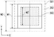
图5A是依照本发明的第一实施例的眼动范围的调整示意图。参考图1、图2以及图5A,预设眼动范围202可为例如图5A所示的范围大小,并且预设眼动范围202中的每一点的出瞳位置坐标可表示为P(x,y,z)。在处理器110进行如上述图4的实施例的根据视力度数的相关计算,以取得缩放比例S之后,处理器110可将预设眼动范围202调整为经调整的眼动范围501或经调整的眼动范围502,其中经调整的眼动范围501及经调整的眼动范围502中的每一点的出瞳位置坐标P′(x,y,z)可表示为以下公式(5)。FIG. 5A is a schematic diagram of adjusting eye movement range according to the first embodiment of the present invention. Referring to Fig. 1, Fig. 2 and Fig. 5A, the preset
P′(x,y,z)=P(x×S,y×S,z)…………公式(5)P'(x,y,z)=P(x×S,y×S,z)………Formula (5)
值得注意的是,眼动范围202在方向X以及方向Y上分别为范围长度W1。对于使用者具有远视的情况下,经调整的眼动范围501在方向X以及方向Y上的范围长度可分别增加为范围长度W2。或者,对于使用者为近视的情况下,经调整的眼动范围502在方向X以及方向Y上的范围长度可分别减少为范围长度W2′。It should be noted that the
接着,处理器110可重新计算从微透镜阵列141的微透镜141_1~141_N的每一个的透镜中心的位置坐标(Pm(x,y,z))分别至经调整的眼动范围501或经调整的眼动范围502中的每一点的出瞳位置的多个(经归一化后的)光线向量


图5B是依照本发明的第二实施例的眼动范围的调整示意图。参考图1、图2、图5B,以散光轴度为0度的规则散光为例,输入至处理器110的视力资料可包括散光度数以及散光轴度。处理器110可根据散光度数以及标准成像距离计算当前成像距离。类似上述图4的架构,在本实施例中,由于标准成像距离D1以及第二当前成像距离D2′远大于出瞳距离Di,因此可具有演算模型中的各参数形成以下公式(7)以及公式(8)的关系,其中微透镜阵列141在方向Y上具有M个微透镜,并且M个微透镜之间各自具有间隔距离WL。值得注意的是,在将公式(7)以及公式(8)相除之后,可产生以下公式(9)的缩放比例S′结果。在公式(9)中,缩放比例S′等于经调整的范围长度W3除以预设眼动范围202在方向Y上的预设范围长度W1的结果。在本实施例中,处理器110可根据以下公式(10)(成像公式)来计算第二当前成像距离D2′。对此,处理器110可根据散光度数D′以及标准成像距离D1计算第二当前成像距离D2′。接着,处理器110可将第二当前成像距离D2′代入公式(9),以获得缩放比例S′。FIG. 5B is a schematic diagram of adjusting the eye movement range according to the second embodiment of the present invention. Referring to FIG. 1 , FIG. 2 , and FIG. 5B , taking regular astigmatism with an axis of astigmatism of 0 degrees as an example, the vision data input to the


如图5B所示,预设眼动范围202中的每一点的出瞳位置坐标可表示为P(x,y,z)。处理器110可执行以下公式(11),以将预设眼动范围202的每一点的出瞳位置坐标P(x,y,z)旋转角度(θ)后进行缩放比例S′的调整,以取得出瞳位置坐标Pt(x,y,z)。接着,处理器110可执行以下公式(12),以将经缩放调整后的每一点的出瞳位置坐标Pt(x,y,z)旋转角度(-θ)后,取得经调整的眼动范围503中的每一点的出瞳位置坐标P"(x,y,z)。As shown in FIG. 5B , the exit pupil position coordinates of each point in the preset
Pt(x,y,z)=P(xcosθ-ysinθ,(xsinθ+ycosθ)×S′,z)…公式(11)Pt(x,y,z)=P(xcosθ-ysinθ,(xsinθ+ycosθ)×S′,z)…Formula (11)
P"(x,y,z)=Pt(xcos(-θ)-ysin(-θ),(xsin(-θ)+ycos(-θ)),z)……公式(12)P"(x,y,z)=Pt(xcos(-θ)-ysin(-θ),(xsin(-θ)+ycos(-θ)),z)...Formula (12)
接着,处理器110可重新计算从微透镜阵列141的微透镜141_1~141_N的每一个的透镜中心的位置坐标(Pm(x,y,z))分别至经调整的眼动范围503中的每一点的出瞳位置的多个(经归一化后的)光线向量

参考图1、图2以及图5C,类似于上述图5B,本实施例以散光轴度为45度的规则散光为例。处理器110可根据上述公式(7)~公式(10)计算缩放比例S′,并且可执行类似于上述公式(11)及公式(12)的计算,以取得经调整的眼动范围504中的每一点的出瞳位置坐标。接着,处理器110可重新计算从微透镜阵列141的微透镜141_1~141_N的每一个的透镜中心的位置坐标(Pm(x,y,z))分别至经调整的眼动范围504中的每一点的出瞳位置的多个(经归一化后的)光线向量。因此,处理器110可根据经调整的眼动范围504中的每一点的出瞳位置坐标以及对应的多个光线向量调整预设影像资料,以使显示面板120可根据经调整的影像资料发射影像光束,以将光场影像显示于瞳孔201的对焦范围内。Referring to FIG. 1 , FIG. 2 and FIG. 5C , similar to the aforementioned FIG. 5B , this embodiment takes regular astigmatism with an axis of astigmatism of 45 degrees as an example. The
图6是依照本发明的一实施例的不规则散光的屈光度分布示意图。图7是依照本发明的第四实施例的眼动范围的调整示意图。参考图1、图2、图6以及图7,在本实施例中,光场近眼显示装置100的储存装置130可预先储存有光学模拟模块。以不规则散光为例,人眼角膜上的不规则散光的屈光度分布可如图6所示的屈光度分布600,其中不同灰阶区域代表屈光度的变化。对此,处理器110可根据屈光度分布600上的屈光度的变化取得对应的多个散光度数以及多个散光轴度。在本实施例中,处理器110可将对应于人眼角膜的多个散光度数以及多个散光轴度输入至光学模拟模块。FIG. 6 is a schematic diagram of a diopter distribution of irregular astigmatism according to an embodiment of the present invention. FIG. 7 is a schematic diagram of adjusting eye movement range according to a fourth embodiment of the present invention. Referring to FIG. 1 , FIG. 2 , FIG. 6 and FIG. 7 , in this embodiment, the
在本实施例中,预设眼动范围701可例如具有由多个格点A1~A25所形成的多个网格范围。处理器110可将多个散光度数以及多个散光轴度输入至光学模拟模块,以使光学模拟模块可根据多个散光度数以及多个散光轴度来调整预设的眼动范围701的多个网格范围。具体而言,预设眼动范围701中的每一个网格各自对应于特定的散光度数以及特定的散光轴度。处理器110可针对预设眼动范围701中的每一个网格分别进行如上述图5B或图5C的计算,以单独调整每一个网格的范围。例如,处理器110可针对预设眼动范围701中的每一个网格的四个角落的位置分别计算经调整的范围所对应的多个出瞳位置坐标以及多个光线向量。因此,预设眼动范围701的格点A1~A25的位置可根据多个散光度数以及多个散光轴度来对应调整其位置,以改变多个网格范围而形成如图7所示的经调整的眼动范围702。值得注意的是,经调整的眼动范围702中的多个格点之间的距离不限于等宽的长度。In this embodiment, the preset
因此,在本实施例中,处理器110可分别根据经调整的眼动范围702的多个经调整的网格范围中的多个出瞳位置坐标计算从微透镜阵列141的多个微透镜141_1~141_N分别到经调整的眼动范围702的这些经调整的网格范围之间的多个光线向量,并且处理器110可根据这些出瞳位置坐标以及这些光线向量调整预设影像资料,以使显示面板120可根据经调整的影像资料发射影像光束,以将光场影像显示于瞳孔201的对焦范围内。Therefore, in this embodiment, the
综上所述,本发明的光场近眼显示装置以及光场近眼显示方法可根据使用者的当前视力资料来自动调整影像资料,以使显示面板可依据经调整的影像资料来发射对应的影像光束,进而使影像光束可正确地入射至使用者的瞳孔,并且光场影像可显示于瞳孔的对焦范围内,如此可让使用者观看到具有良好影像品质的光场影像。In summary, the light field near-eye display device and the light field near-eye display method of the present invention can automatically adjust the image data according to the user's current vision data, so that the display panel can emit corresponding image beams according to the adjusted image data , so that the image beam can be correctly incident on the pupil of the user, and the light field image can be displayed within the focus range of the pupil, so that the user can watch the light field image with good image quality.
以上所述仅为本发明的优选实施例而已,当不能以此限定本发明实施的范围,即凡是依照本发明的权利要求书及本发明的说明书所作的简单的等效变化与修饰皆仍处于本发明专利涵盖的范围内。另外本发明的任一实施例或权利要求书不须实现本发明所公开的全部目的或优点或特点。此外,说明书摘要和发明名称仅是用来辅助专利文件检索之用,并非用来限制本发明的权利范围。此外,本说明书或权利要求书中提及的”第一”、“第二”等用语仅用以命名元件(element)的名称或区别不同实施例或范围,而并非用来限制元件数量上的上限或下限。The above description is only a preferred embodiment of the present invention, and should not limit the scope of the present invention, that is, all simple equivalent changes and modifications made according to the claims of the present invention and the description of the present invention are still within the scope of the present invention. Within the scope covered by the patent of the present invention. In addition, any embodiment or claims of the present invention need not achieve all the objects or advantages or features disclosed in the present invention. In addition, the abstract of the description and the title of the invention are only used to assist in the search of patent documents, and are not used to limit the scope of rights of the present invention. In addition, terms such as "first" and "second" mentioned in the specification or claims are only used to name elements or to distinguish different embodiments or ranges, and are not used to limit the number of elements. upper or lower limit.
附图文字列表Attached text list
100:光场近眼显示装置100: Light field near-eye display device
110:处理器110: Processor
120:显示面板120: display panel
121_1、121_2、121_3:子影像内容121_1, 121_2, 121_3: sub image content
130:储存装置130: storage device
140:透镜模块140: Lens module
141:微透镜阵列141: microlens array
141_1~141_N:微透镜141_1~141_N: micro lens
142:第一透镜142: first lens
143:第二透镜143: second lens
151_1、151_2、151_3:子虚拟影像151_1, 151_2, 151_3: sub-virtual images
201:瞳孔201: Pupil
202、701:预设眼动范围202, 701: preset eye movement range
401:虚拟矫正负透镜401: Virtual Corrective Negative Lens
501、502、503、504、702:经调整的眼动范围501, 502, 503, 504, 702: Adjusted eye range
600:屈光度分布600: diopter distribution
A1~A25:格点A1~A25: grid points
Di:出瞳距离Di: exit pupil distance
D1:标准成像距离D1: standard imaging distance
D2:第一当前成像距离D2: The first current imaging distance
D2′:第二当前成像距离D2': the second current imaging distance
S1、RDP1、RDP2:虚拟成像平面S1, RDP1, RDP2: virtual imaging plane
X、Y、Z:方向X, Y, Z: direction
S310、S320、S330、S340:步骤S310, S320, S330, S340: steps
W1:预设范围长度W1: preset range length
W2、W2′、W3:经调整的范围长度W2, W2′, W3: Adjusted range length
WL:间隔距离。WL: Separation distance.
Claims (20)
Translated fromChinesePriority Applications (3)
| Application Number | Priority Date | Filing Date | Title |
|---|---|---|---|
| US17/724,501US11841513B2 (en) | 2021-05-13 | 2022-04-20 | Light field near-eye display device and method of light field near-eye display |
| JP2022070698AJP2022176110A (en) | 2021-05-13 | 2022-04-22 | Light field near-eye display device and light field near-eye display method |
| EP22169794.9AEP4089468A1 (en) | 2021-05-13 | 2022-04-25 | Light field near-eye display device and method of light field near-eye display |
Applications Claiming Priority (2)
| Application Number | Priority Date | Filing Date | Title |
|---|---|---|---|
| US202163187948P | 2021-05-13 | 2021-05-13 | |
| US63/187,948 | 2021-05-13 |
Publications (2)
| Publication Number | Publication Date |
|---|---|
| CN115343849Atrue CN115343849A (en) | 2022-11-15 |
| CN115343849B CN115343849B (en) | 2025-09-23 |
Family
ID=83947217
Family Applications (1)
| Application Number | Title | Priority Date | Filing Date |
|---|---|---|---|
| CN202111132762.3AActiveCN115343849B (en) | 2021-05-13 | 2021-09-27 | Light field near-eye display device and light field near-eye display method |
Country Status (2)
| Country | Link |
|---|---|
| CN (1) | CN115343849B (en) |
| TW (1) | TWI798842B (en) |
Citations (5)
| Publication number | Priority date | Publication date | Assignee | Title |
|---|---|---|---|---|
| CN104914575A (en)* | 2014-09-29 | 2015-09-16 | 北京蚁视科技有限公司 | Microlens-array-type near-eye display with diopter detection device |
| CN107015362A (en)* | 2016-01-28 | 2017-08-04 | 中强光电股份有限公司 | Head-mounted display device |
| CN107991775A (en)* | 2016-10-26 | 2018-05-04 | 中国科学院深圳先进技术研究院 | It can carry out the wear-type visual device and human eye method for tracing of people's ocular pursuit |
| US20200272232A1 (en)* | 2018-10-22 | 2020-08-27 | Evolution Optiks Limited | Light field dislay, adjusted pixel rendering method therefor, and adjusted vision perception system and method using same addressing astigmatism or similar conditions |
| US10890767B1 (en)* | 2017-09-27 | 2021-01-12 | United Services Automobile Association (Usaa) | System and method for automatic vision correction in near-to-eye displays |
Family Cites Families (2)
| Publication number | Priority date | Publication date | Assignee | Title |
|---|---|---|---|---|
| EP3409013B1 (en)* | 2016-01-29 | 2022-01-05 | Hewlett-Packard Development Company, L.P. | Viewing device adjustment based on eye accommodation in relation to a display |
| TWI704377B (en)* | 2019-09-09 | 2020-09-11 | 宏碁股份有限公司 | Head-mounted display apparatus and visual inspection method thereof |
- 2021
- 2021-09-27CNCN202111132762.3Apatent/CN115343849B/enactiveActive
- 2021-09-27TWTW110135752Apatent/TWI798842B/enactive
Patent Citations (5)
| Publication number | Priority date | Publication date | Assignee | Title |
|---|---|---|---|---|
| CN104914575A (en)* | 2014-09-29 | 2015-09-16 | 北京蚁视科技有限公司 | Microlens-array-type near-eye display with diopter detection device |
| CN107015362A (en)* | 2016-01-28 | 2017-08-04 | 中强光电股份有限公司 | Head-mounted display device |
| CN107991775A (en)* | 2016-10-26 | 2018-05-04 | 中国科学院深圳先进技术研究院 | It can carry out the wear-type visual device and human eye method for tracing of people's ocular pursuit |
| US10890767B1 (en)* | 2017-09-27 | 2021-01-12 | United Services Automobile Association (Usaa) | System and method for automatic vision correction in near-to-eye displays |
| US20200272232A1 (en)* | 2018-10-22 | 2020-08-27 | Evolution Optiks Limited | Light field dislay, adjusted pixel rendering method therefor, and adjusted vision perception system and method using same addressing astigmatism or similar conditions |
Also Published As
| Publication number | Publication date |
|---|---|
| TWI798842B (en) | 2023-04-11 |
| CN115343849B (en) | 2025-09-23 |
| TW202245465A (en) | 2022-11-16 |
Similar Documents
| Publication | Publication Date | Title |
|---|---|---|
| US12124040B2 (en) | Augmented reality display comprising eyepiece having a transparent emissive display | |
| US12282170B2 (en) | Augmented and virtual reality display systems with correlated in-coupling and out-coupling optical regions for efficient light utilization | |
| US10271042B2 (en) | Calibration of a head mounted eye tracking system | |
| KR102664868B1 (en) | Light projector using an acousto-optical control device | |
| JP2020202569A (en) | Virtual eyeglass set for viewing actual scene that corrects for different location of lenses than eyes | |
| KR20240023213A (en) | Augmented reality display having multi-element adaptive lens for changing depth planes | |
| KR20240046291A (en) | Depth based foveated rendering for display systems | |
| CN104777616B (en) | Have an X-rayed wear-type light field display device | |
| CN114600032A (en) | Light field vision testing device, adjusted pixel rendering method for the same, and vision testing system and method using the same | |
| CN114930443A (en) | Light field device, multi-depth pixel rendering method therefor, and multi-depth vision perception system and method using same | |
| US10819898B1 (en) | Imaging device with field-of-view shift control | |
| CN104094162A (en) | Wide field of view 3D stereo vision platform for dynamic control of immersion or head-up display operation | |
| US11841513B2 (en) | Light field near-eye display device and method of light field near-eye display | |
| US11842662B2 (en) | Light field near-eye display device for automatically adjusting image data according to current eye relief and method thereof | |
| TWI745000B (en) | Light field near-eye display device and method of light field near-eye display | |
| TWI798842B (en) | Light field near-eye display device and method of light field near-eye display | |
| JP2019056738A (en) | Display device | |
| CN112987297B (en) | Light field near-eye display device and light field near-eye display method | |
| TWI794948B (en) | Light field near-eye display device and method of light field near-eye display | |
| CN115151853A (en) | Method for displaying a sharp image on the retina of a human eye | |
| CN211791831U (en) | Integrated imaging display system | |
| WO2024077314A9 (en) | Perspective-invariant varifocal eyeglass system | |
| WO2024151427A1 (en) | Gradient-index liquid crystal lens system including guest-host liquid crystal layer for reducing light leakage | |
| CN110933396A (en) | Integrated imaging display system and display method thereof |
Legal Events
| Date | Code | Title | Description |
|---|---|---|---|
| PB01 | Publication | ||
| PB01 | Publication | ||
| SE01 | Entry into force of request for substantive examination | ||
| SE01 | Entry into force of request for substantive examination | ||
| GR01 | Patent grant | ||
| GR01 | Patent grant |