CN115338865B - Measuring method of grasping effect of enveloping capture of non-cooperative targets in space - Google Patents
Measuring method of grasping effect of enveloping capture of non-cooperative targets in spaceDownload PDFInfo
- Publication number
- CN115338865B CN115338865BCN202210993124.9ACN202210993124ACN115338865BCN 115338865 BCN115338865 BCN 115338865BCN 202210993124 ACN202210993124 ACN 202210993124ACN 115338865 BCN115338865 BCN 115338865B
- Authority
- CN
- China
- Prior art keywords
- contact
- point
- grabbing
- algorithm
- expressed
- Prior art date
- Legal status (The legal status is an assumption and is not a legal conclusion. Google has not performed a legal analysis and makes no representation as to the accuracy of the status listed.)
- Active
Links
- 238000000034methodMethods0.000titleclaimsabstractdescription20
- 230000000694effectsEffects0.000titleclaimsabstractdescription18
- 238000004422calculation algorithmMethods0.000claimsabstractdescription46
- 238000005457optimizationMethods0.000claimsabstractdescription12
- 239000013598vectorSubstances0.000claimsdescription15
- 239000011159matrix materialSubstances0.000claimsdescription9
- 238000004088simulationMethods0.000claimsdescription7
- 238000004364calculation methodMethods0.000claimsdescription6
- 238000010606normalizationMethods0.000claims1
- 238000000691measurement methodMethods0.000abstractdescription10
- 238000010586diagramMethods0.000description5
- 238000005259measurementMethods0.000description5
- 101100233916Saccharomyces cerevisiae (strain ATCC 204508 / S288c) KAR5 geneProteins0.000description2
- 230000009286beneficial effectEffects0.000description1
- 238000002922simulated annealingMethods0.000description1
Images


Classifications
- B—PERFORMING OPERATIONS; TRANSPORTING
- B25—HAND TOOLS; PORTABLE POWER-DRIVEN TOOLS; MANIPULATORS
- B25J—MANIPULATORS; CHAMBERS PROVIDED WITH MANIPULATION DEVICES
- B25J9/00—Programme-controlled manipulators
- B25J9/16—Programme controls
- B25J9/1602—Programme controls characterised by the control system, structure, architecture
- B25J9/1607—Calculation of inertia, jacobian matrixes and inverses
- Y—GENERAL TAGGING OF NEW TECHNOLOGICAL DEVELOPMENTS; GENERAL TAGGING OF CROSS-SECTIONAL TECHNOLOGIES SPANNING OVER SEVERAL SECTIONS OF THE IPC; TECHNICAL SUBJECTS COVERED BY FORMER USPC CROSS-REFERENCE ART COLLECTIONS [XRACs] AND DIGESTS
- Y02—TECHNOLOGIES OR APPLICATIONS FOR MITIGATION OR ADAPTATION AGAINST CLIMATE CHANGE
- Y02T—CLIMATE CHANGE MITIGATION TECHNOLOGIES RELATED TO TRANSPORTATION
- Y02T90/00—Enabling technologies or technologies with a potential or indirect contribution to GHG emissions mitigation
Landscapes
- Engineering & Computer Science (AREA)
- Physics & Mathematics (AREA)
- Mathematical Physics (AREA)
- Automation & Control Theory (AREA)
- Robotics (AREA)
- Mechanical Engineering (AREA)
- A Measuring Device Byusing Mechanical Method (AREA)
- Manipulator (AREA)
Abstract
Description
Translated fromChinese技术领域Technical Field
本发明属于在轨服务空间非合作目标的抓捕技术领域,特别是涉及空间非合作目标包络式抓捕的抓取效果衡量方法。The present invention belongs to the technical field of capturing non-cooperative targets in orbital service space, and in particular relates to a capture effect measurement method for envelope capture of non-cooperative targets in space.
背景技术Background Art
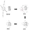
空间非合作目标包络式抓捕是一种抓捕可靠性非常高的方法,该方法的抓捕示意过程如图1所示。这种方法不需要合作接口以及一些可供抓捕的突出特征,其抓捕普适性也非常高。由于这种特性,包络式抓捕的可抓捕区域较大,因此在抓捕之前需要选择一组抓取效果较好的接触点。通常一组抓取接触点需要具有如下特征:所形成的抓捕结构能够抵御来自各个方向上的干扰力以及干扰力矩,同时接触点在目标表面具有广泛的分布,来使抵御干扰所需的平均接触力尽量小。The envelope capture of non-cooperative targets in space is a method with very high capture reliability. The capture schematic process of this method is shown in Figure 1. This method does not require a cooperative interface and some outstanding features for capture, and its capture universality is also very high. Due to this characteristic, the capture area of the envelope capture is large, so a set of contact points with better capture effect needs to be selected before capture. Usually a set of capture contact points needs to have the following characteristics: the capture structure formed can resist interference forces and interference torques from all directions, and the contact points are widely distributed on the target surface to minimize the average contact force required to resist interference.
目前的抓取效果衡量算法主要针对地面目标,使用机器人灵巧手对目标进行指尖抓捕(弱抓捕)。而空间非合作目标包络式抓捕与机器人灵巧手的指尖抓捕的区别主要在于抓捕点分布的问题。包络式抓捕具有一个基座接触点和多个机械臂接触点,其机械臂接触点的个数与机械臂个数相同。基座接触点与机械臂接触点分布在目标的两端,这产生了一个机械臂接触点分布的约束。传统算法的接触点衡量算法不适用这种约束。在使用传统衡量算法进行优化时,优化结果将会出现机械臂接触点太过靠近质心平面的情况。其靠近质心平面的程度与机械臂接触点个数有关,机械臂接触点个数越多,接触点越靠近质心平面,这种情况如图2所示。The current grasping effect measurement algorithm is mainly aimed at ground targets, using a robot dexterous hand to perform fingertip grasping (weak grasping) on the target. The difference between the envelope grasping of space non-cooperative targets and the fingertip grasping of the robot dexterous hand lies mainly in the distribution of grasping points. The envelope grasping has a base contact point and multiple robot arm contact points, and the number of robot arm contact points is the same as the number of robot arms. The base contact point and the robot arm contact point are distributed at both ends of the target, which creates a constraint on the distribution of robot arm contact points. The contact point measurement algorithm of the traditional algorithm does not apply to this constraint. When using the traditional measurement algorithm for optimization, the optimization result will show that the robot arm contact point is too close to the center of mass plane. The degree of its proximity to the center of mass plane is related to the number of robot arm contact points. The more robot arm contact points there are, the closer the contact point is to the center of mass plane. This situation is shown in Figure 2.
发明内容Summary of the invention
本发明目的是为了解决优化接触点在机械臂接触一侧分布不够广泛,抵御干扰能力较差的问题,提供了空间非合作目标包络式抓捕的抓取效果衡量方法。The purpose of the present invention is to solve the problem that the optimized contact points are not widely distributed on the contact side of the robot arm and the interference resistance ability is poor, and a grasping effect measurement method for envelope capture of spatial non-cooperative targets is provided.
本发明是通过以下技术方案实现的,本发明提出空间非合作目标包络式抓捕的抓取效果衡量方法,所述方法包括虚拟对称点算法抓取和几何算法抓取两部分;The present invention is realized by the following technical scheme. The present invention proposes a grasping effect measurement method for envelope-type grasping of space non-cooperative targets. The method includes two parts: grasping by virtual symmetric point algorithm and grasping by geometric algorithm.
所述虚拟对称点算法具体为:对于一个待抓捕目标,分布在其表面的机械臂接触点在惯性系下表示为


接触力表示为接触点处接触法向力和接触摩擦力的合力,这两个力形成一个摩擦锥;由于摩擦力的幅值ff≤μfN,因此三维情况下包含法向接触力和摩擦力的接触约束表示为:The contact force is expressed as the resultant of the contact normal force and the contact friction force at the contact point. These two forces form a friction cone. Since the amplitude of the friction force ff ≤ μfN , the contact constraint including the normal contact force and the friction force in three dimensions is expressed as:
Cμ={fi|||(I3×3-ssT)fi||≤μfi·s}Cμ ={fi |||(I3×3 -ssT )fi ||≤μfi ·s}
其中fi表示第i个接触点处的接触力,s表示第i个接触点处的法向量在接触系下的投影;Wherefi represents the contact force at the i-th contact point, and s represents the projection of the normal vector at the i-th contact point in the contact system;
将摩擦锥线性化以进行线性规划工作,则fi可表示为:Linearizing the friction cone for linear programming work,fi can be expressed as:

其中0<αij<1,ωij=Gilij为接触力螺旋在惯性系下的表示,lij为第i个接触点处的摩擦锥的第j条棱,则n个接触点对目标施加的接触力为:Where 0<αij <1, ωij =Gi lij is the representation of the contact force spiral in the inertial system, lij is the jth edge of the friction cone at the i-th contact point, then the contact force exerted by n contact points on the target is:

已知质心平面与基座接触平面平行,且通过目标的质心,将机械臂接触点相对质心平面进行对称操作,得到虚拟对称接触点,其个数与机械臂接触点相同;用虚拟对称接触点来代替基座接触点,虚拟对称接触点可表示为


其中
所述几何算法具体为:首先求出目标表面所有点与质心的平均距离mp;之后将所有机械臂接触点和虚拟对称接触点形成的点集


几何算法可表示为:The geometric algorithm can be expressed as:

其中A为面积计算函数,V为体积计算函数;Where A is the area calculation function, and V is the volume calculation function;
建立联合仿真,其显式优化变量为接触点的位置,则空间非合作目标包络式抓捕的抓取效果衡量方法表示为:A joint simulation is established, and its explicit optimization variable is the position of the contact point. Then the grasping effect measurement method of the spatial non-cooperative target envelope grasping is expressed as:

进一步地,所述摩擦锥为六棱锥,即m=6。Furthermore, the friction cone is a hexagonal pyramid, that is, m=6.
进一步地,与虚拟对称接触点相关的部分需要满足以下约束:Furthermore, the parts related to the virtual symmetric contact points need to satisfy the following constraints:

该约束代表虚拟对称接触点所产生的接触力螺旋需要满足基座能产生的接触力螺旋约束。This constraint means that the contact force spiral generated by the virtual symmetric contact point needs to satisfy the contact force spiral constraint that the base can generate.
进一步地,所述基座和目标之间具有三种接触形式:面接触,线接触与点接触;面接触能够产生三个方向的约束力矩,线接触只能产生两个方向上的接触力矩,而点接触不能产生约束力矩;根据这种形式对ωbase满足的约束进行修正,同时将修正后的约束反映到虚拟对称点算法中来调节优化参数。Furthermore, there are three contact forms between the base and the target: surface contact, line contact and point contact; surface contact can generate constraint torques in three directions, line contact can only generate contact torques in two directions, and point contact cannot generate constraint torques; according to this form, the constraints satisfied by ωbase are corrected, and the corrected constraints are reflected in the virtual symmetry point algorithm to adjust the optimization parameters.
进一步地,λ1=1,λ2=0.04。Further, λ1 =1, λ2 =0.04.
本发明的有益效果:Beneficial effects of the present invention:
本发明提出了一种空间非合作目标包络式抓捕的抓取效果衡量方法。所述衡量方法在机械臂接触点形成的抓捕构型分布较为广泛的时候达到最优值,同时保证能够抵御各个方向上的干扰。同时,在配合优化算法进行最优接触构型搜索时,本发明所述的抓取效果衡量算法可用于二维抓取情况与三维抓取情况,具有鞍点少的特点,更容易达到全局最优点。The present invention proposes a grasping effect measurement method for envelope grasping of non-cooperative targets in space. The measurement method reaches the optimal value when the grasping configuration formed by the contact points of the manipulator is widely distributed, while ensuring that it can resist interference in all directions. At the same time, when the optimal contact configuration is searched in conjunction with the optimization algorithm, the grasping effect measurement algorithm of the present invention can be used for two-dimensional grasping and three-dimensional grasping, has the characteristics of fewer saddle points, and is easier to reach the global optimal point.
附图说明BRIEF DESCRIPTION OF THE DRAWINGS
图1是现有技术中空间非合作目标包络式抓捕示意图。FIG. 1 is a schematic diagram of envelope capture of non-cooperative targets in space in the prior art.
图2是现有方法接触点分布图。FIG. 2 is a distribution diagram of contact points of the existing method.
图3是接触模型示意图。FIG3 is a schematic diagram of the contact model.
图4是虚拟对称接触点示意图。FIG. 4 is a schematic diagram of virtual symmetrical contact points.
图5是三维情况的几何算法示意图。FIG5 is a schematic diagram of the geometric algorithm for the three-dimensional case.
图6是圆柱体仿真结果对照图。FIG6 is a comparison chart of the simulation results of a cylinder.
图7是球体仿真结果对照图。FIG. 7 is a comparison chart of sphere simulation results.
具体实施方式DETAILED DESCRIPTION
下面将结合本发明实施例中的附图对本发明实施例中的技术方案进行清楚、完整地描述,显然,所描述的实施例仅仅是本发明一部分实施例,而不是全部的实施例。基于本发明中的实施例,本领域普通技术人员在没有做出创造性劳动前提下所获得的所有其他实施例,都属于本发明保护的范围。The technical solutions in the embodiments of the present invention will be described clearly and completely below in conjunction with the drawings in the embodiments of the present invention. Obviously, the described embodiments are only part of the embodiments of the present invention, not all of the embodiments. Based on the embodiments of the present invention, all other embodiments obtained by ordinary technicians in this field without creative work are within the scope of protection of the present invention.
结合图1-图7,本发明提出空间非合作目标包络式抓捕的抓取效果衡量方法,所述抓取效果衡量方法是一个多目标联合算法,所述方法包括虚拟对称点算法抓取和几何算法抓取两部分;In conjunction with FIG. 1 to FIG. 7 , the present invention proposes a grasping effect measurement method for envelope-type grasping of spatial non-cooperative targets. The grasping effect measurement method is a multi-target joint algorithm. The method includes two parts: grasping by a virtual symmetric point algorithm and grasping by a geometric algorithm.
如图3所示,所述虚拟对称点算法具体为:对于一个待抓捕目标,分布在其表面的机械臂接触点在惯性系下表示为


接触力表示为接触点处接触法向力和接触摩擦力的合力,这两个力形成一个摩擦锥;由于摩擦力的幅值ff≤μfN,因此三维情况下包含法向接触力和摩擦力的接触约束表示为:The contact force is expressed as the resultant of the contact normal force and the contact friction force at the contact point. These two forces form a friction cone. Since the amplitude of the friction force ff ≤ μfN , the contact constraint including the normal contact force and the friction force in three dimensions is expressed as:
Cμ={fi|||(I3×3-ssT)fi||≤μfi·s}Cμ ={fi |||(I3×3 -ssT )fi ||≤μfi ·s}
其中fi表示第i个接触点处的接触力,在图3中fi表示接触点
为了便于优化,通常将摩擦锥线性化以进行线性规划工作,线性化的摩擦锥如图3所示,则fi可表示为:In order to facilitate optimization, the friction cone is usually linearized for linear programming. The linearized friction cone is shown in Figure 3, andfi can be expressed as:

其中0<αij<1,ωij=Gilij为接触力螺旋在惯性系下的表示,lij为第i个接触点处的摩擦锥的第j条棱,所述摩擦锥为六棱锥,即m=6。则n个接触点对目标施加的接触力为:Where 0<αij <1, ωij =Gi lij is the representation of the contact force spiral in the inertial system, lij is the jth edge of the friction cone at the i-th contact point, and the friction cone is a hexagonal pyramid, that is, m=6. Then the contact force applied by n contact points on the target is:

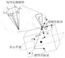
一个目标上的接触点如图4所示,已知质心平面与基座接触平面平行,且通过目标的质心,将机械臂接触点相对质心平面进行对称操作,得到虚拟对称接触点,其个数与机械臂接触点相同;用虚拟对称接触点来代替基座接触点,虚拟对称接触点可表示为


其中
与虚拟对称接触点相关的部分需要满足以下约束:The parts related to the virtual symmetric contact points need to meet the following constraints:

该约束代表虚拟对称接触点所产生的接触力螺旋需要满足基座能产生的接触力螺旋约束。ωbase中力的部分在满足法向接触力和摩擦力的接触约束的同时,力矩的部分还需要满足相应的约束。所述基座和目标之间具有三种接触形式:面接触,线接触与点接触;面接触能够产生三个方向的约束力矩,线接触只能产生两个方向上的接触力矩,而点接触不能产生约束力矩;根据这种形式对ωbase满足的约束进行修正,同时将修正后的约束反映到虚拟对称点算法中来调节优化参数。This constraint represents that the contact force spiral generated by the virtual symmetric contact point needs to satisfy the contact force spiral constraint that the base can generate. While the force part in ωbase satisfies the contact constraints of the normal contact force and the friction force, the torque part also needs to satisfy the corresponding constraints. There are three contact forms between the base and the target: surface contact, line contact and point contact; surface contact can generate constraint torques in three directions, line contact can only generate contact torques in two directions, and point contact cannot generate constraint torques; according to this form, the constraints satisfied by ωbase are corrected, and the corrected constraints are reflected in the virtual symmetric point algorithm to adjust the optimization parameters.
所述几何算法具体为:首先求出目标表面所有点与质心的平均距离mp;之后将所有机械臂接触点和虚拟对称接触点形成的点集


三维情况的几何算法如图5所示。几何算法可表示为:The geometric algorithm for the three-dimensional case is shown in Figure 5. The geometric algorithm can be expressed as:

其中A为面积计算函数,V为体积计算函数;Where A is the area calculation function, and V is the volume calculation function;
建立联合仿真,其显式优化变量为接触点的位置,则空间非合作目标包络式抓捕的抓取效果衡量方法表示为:A joint simulation is established, and its explicit optimization variable is the position of the contact point. Then the grasping effect measurement method of the spatial non-cooperative target envelope grasping is expressed as:

一般情况下,λ1=1,λ2=0.04。Generally, λ1 =1, λ2 =0.04.
将本发明中所提出的抓取效果衡量算法与模拟退火算法相结合来搜寻全局最优,以得到最理想的抓取点组合。分别建立两种模型来运用现有技术中的算法和本发明中的算法进行验证,得到的全局最优点如图6和图7所示。图6是圆柱体仿真结果对照图。图7是球体仿真结果对照图,相比之下,本发明中的算法得到的优化结果能更好的抵御各个方向上的干扰。The grab effect measurement algorithm proposed in the present invention is combined with the simulated annealing algorithm to search for the global optimum to obtain the most ideal grab point combination. Two models are established to verify the algorithm in the prior art and the algorithm in the present invention, and the obtained global optimum is shown in Figures 6 and 7. Figure 6 is a comparison chart of the simulation results of a cylinder. Figure 7 is a comparison chart of the simulation results of a sphere. In comparison, the optimization result obtained by the algorithm in the present invention can better resist interference in all directions.
以上对本发明所提出的空间非合作目标包络式抓捕的抓取效果衡量方法进行了详细介绍,本文中应用了具体个例对本发明的原理及实施方式进行了阐述,以上实施例的说明只是用于帮助理解本发明的方法及其核心思想;同时,对于本领域的一般技术人员,依据本发明的思想,在具体实施方式及应用范围上均会有改变之处,综上所述,本说明书内容不应理解为对本发明的限制。The above is a detailed introduction to the method for measuring the capture effect of the envelope capture of spatial non-cooperative targets proposed in the present invention. This article uses specific examples to illustrate the principles and implementation methods of the present invention. The description of the above embodiments is only used to help understand the method of the present invention and its core idea; at the same time, for general technical personnel in this field, according to the idea of the present invention, there will be changes in the specific implementation method and application scope. In summary, the content of this specification should not be understood as a limitation on the present invention.
Claims (3)


Priority Applications (1)
| Application Number | Priority Date | Filing Date | Title |
|---|---|---|---|
| CN202210993124.9ACN115338865B (en) | 2022-08-18 | 2022-08-18 | Measuring method of grasping effect of enveloping capture of non-cooperative targets in space |
Applications Claiming Priority (1)
| Application Number | Priority Date | Filing Date | Title |
|---|---|---|---|
| CN202210993124.9ACN115338865B (en) | 2022-08-18 | 2022-08-18 | Measuring method of grasping effect of enveloping capture of non-cooperative targets in space |
Publications (2)
| Publication Number | Publication Date |
|---|---|
| CN115338865A CN115338865A (en) | 2022-11-15 |
| CN115338865Btrue CN115338865B (en) | 2023-05-09 |
Family
ID=83954283
Family Applications (1)
| Application Number | Title | Priority Date | Filing Date |
|---|---|---|---|
| CN202210993124.9AActiveCN115338865B (en) | 2022-08-18 | 2022-08-18 | Measuring method of grasping effect of enveloping capture of non-cooperative targets in space |
Country Status (1)
| Country | Link |
|---|---|
| CN (1) | CN115338865B (en) |
Family Cites Families (6)
| Publication number | Priority date | Publication date | Assignee | Title |
|---|---|---|---|---|
| CN102935642B (en)* | 2012-11-09 | 2015-02-18 | 清华大学 | Connection rod key slot type coupling under-actuated double-joint robot finger device |
| CN103009389B (en)* | 2012-11-30 | 2015-07-08 | 北京控制工程研究所 | Track planning method of redundant space mechanical arm for on-track catching |
| JP5718394B2 (en)* | 2013-03-12 | 2015-05-13 | 株式会社ブリヂストン | Grab device |
| CN106945020B (en)* | 2017-05-18 | 2019-10-22 | 哈尔滨工业大学 | A Coordinated Motion Control Method for Space Dual Manipulator System |
| US11850751B2 (en)* | 2018-07-17 | 2023-12-26 | Sony Corporation | Control device, control method, and control system |
| CN112009729B (en)* | 2020-08-04 | 2021-09-21 | 北京航空航天大学 | Spherical outer envelope capturing method for space robot |
- 2022
- 2022-08-18CNCN202210993124.9Apatent/CN115338865B/enactiveActive
Also Published As
| Publication number | Publication date |
|---|---|
| CN115338865A (en) | 2022-11-15 |
Similar Documents
| Publication | Publication Date | Title |
|---|---|---|
| CN108932216B (en) | A solution method of robot inverse kinematics based on particle swarm optimization algorithm | |
| CN109895101B (en) | A method for obtaining unique numerical solution of inverse kinematics of articulated manipulator | |
| CN111168675B (en) | Dynamic obstacle avoidance motion planning method for mechanical arm of household service robot | |
| CN112669385B (en) | Industrial robot part identification and pose estimation method based on three-dimensional point cloud features | |
| CN113500017B (en) | An intelligent system and method for material sorting in unstructured scenarios | |
| CN103020960B (en) | Based on the point cloud registration method of convex closure unchangeability | |
| CN107225576B (en) | A kind of control method based on soft finger | |
| CN111360862B (en) | Method for generating optimal grabbing pose based on convolutional neural network | |
| CN114329986B (en) | Anthropomorphic kinematics inverse solution method for redundant robotic arms based on human musculoskeletal model | |
| Marcum | Efficient generation of high-quality unstructured surface and volume grids | |
| CN104809276B (en) | A kind of many finger robot dynamics analytic modell analytical models and its modeling method | |
| CN114117625B (en) | Large member pose optimization method driven by butt joint separating surface gap | |
| CN107203653B (en) | A general solution method for inverse kinematics of a 6-DOF serial robot | |
| CN113580135B (en) | Real-time inverse solution method for seven-axis robot with offset | |
| CN113070877B (en) | Variable attitude mapping method for seven-axis mechanical arm visual teaching | |
| CN107160401B (en) | A method for solving the joint angle offset problem of redundant manipulators | |
| CN116038647A (en) | Scooter, control method of mechanical arm, electronic equipment and storage medium | |
| CN111546376A (en) | A fast self-collision detection method for a space combined manipulator | |
| CN109333497A (en) | A remote operating system control method with virtual binding force | |
| CN116985132A (en) | Method and device for picking simulated learning fruits based on multi-modal information fusion | |
| CN105573143A (en) | Inverse kinematics solving method for 6-DOF (degree of freedom) industrial robot | |
| CN115338865B (en) | Measuring method of grasping effect of enveloping capture of non-cooperative targets in space | |
| CN107255926B (en) | A method for quickly solving the joint angle offset problem of redundant manipulators | |
| CN106527151B (en) | A Path Search Method for a Space Manipulator with Loaded Six Degrees of Freedom | |
| CN110371325A (en) | A kind of adaptive envelope of inert satellite based on super redundant mechanical arm arrests method |
Legal Events
| Date | Code | Title | Description |
|---|---|---|---|
| PB01 | Publication | ||
| PB01 | Publication | ||
| SE01 | Entry into force of request for substantive examination | ||
| SE01 | Entry into force of request for substantive examination | ||
| GR01 | Patent grant | ||
| GR01 | Patent grant |