CN115337132A - Conveying Devices and Systems - Google Patents
Conveying Devices and SystemsDownload PDFInfo
- Publication number
- CN115337132A CN115337132ACN202210367158.7ACN202210367158ACN115337132ACN 115337132 ACN115337132 ACN 115337132ACN 202210367158 ACN202210367158 ACN 202210367158ACN 115337132 ACN115337132 ACN 115337132A
- Authority
- CN
- China
- Prior art keywords
- guide wire
- joint
- assembly
- tube
- delivery device
- Prior art date
- Legal status (The legal status is an assumption and is not a legal conclusion. Google has not performed a legal analysis and makes no representation as to the accuracy of the status listed.)
- Pending
Links
- 230000007246mechanismEffects0.000claimsdescription28
- 230000000149penetrating effectEffects0.000abstractdescription4
- 238000004891communicationMethods0.000description12
- 238000010586diagramMethods0.000description10
- 230000007704transitionEffects0.000description7
- HZEWFHLRYVTOIW-UHFFFAOYSA-N[Ti].[Ni]Chemical compound[Ti].[Ni]HZEWFHLRYVTOIW-UHFFFAOYSA-N0.000description4
- 238000002347injectionMethods0.000description4
- 239000007924injectionSubstances0.000description4
- 238000000034methodMethods0.000description4
- 229910001000nickel titaniumInorganic materials0.000description4
- 230000009471actionEffects0.000description3
- 210000004204blood vesselAnatomy0.000description3
- 239000000463materialSubstances0.000description3
- 229910052751metalInorganic materials0.000description3
- 239000002184metalSubstances0.000description3
- 238000006073displacement reactionMethods0.000description2
- 239000000945fillerSubstances0.000description2
- 239000003292glueSubstances0.000description2
- 230000003902lesionEffects0.000description2
- 239000007788liquidSubstances0.000description2
- 239000012528membraneSubstances0.000description2
- 230000008569processEffects0.000description2
- 238000012545processingMethods0.000description2
- 238000007789sealingMethods0.000description2
- 201000008982Thoracic Aortic AneurysmDiseases0.000description1
- 208000002223abdominal aortic aneurysmDiseases0.000description1
- 238000004026adhesive bondingMethods0.000description1
- 238000005452bendingMethods0.000description1
- 230000009286beneficial effectEffects0.000description1
- 230000017531blood circulationEffects0.000description1
- 238000009954braidingMethods0.000description1
- 230000007547defectEffects0.000description1
- 238000013461designMethods0.000description1
- 238000002224dissectionMethods0.000description1
- 239000003814drugSubstances0.000description1
- 230000007717exclusionEffects0.000description1
- 230000014509gene expressionEffects0.000description1
- 238000002844meltingMethods0.000description1
- 230000008018meltingEffects0.000description1
- 238000012986modificationMethods0.000description1
- 230000004048modificationEffects0.000description1
- 239000004810polytetrafluoroethyleneSubstances0.000description1
- 229920001343polytetrafluoroethylenePolymers0.000description1
- 238000002360preparation methodMethods0.000description1
- 238000007493shaping processMethods0.000description1
- 239000007787solidSubstances0.000description1
- 239000000243solutionSubstances0.000description1
- 229910001220stainless steelInorganic materials0.000description1
- 239000010935stainless steelSubstances0.000description1
- 230000003068static effectEffects0.000description1
- 230000003746surface roughnessEffects0.000description1
- 210000000115thoracic cavityAnatomy0.000description1
- 230000002792vascularEffects0.000description1
Images


Classifications
- A—HUMAN NECESSITIES
- A61—MEDICAL OR VETERINARY SCIENCE; HYGIENE
- A61F—FILTERS IMPLANTABLE INTO BLOOD VESSELS; PROSTHESES; DEVICES PROVIDING PATENCY TO, OR PREVENTING COLLAPSING OF, TUBULAR STRUCTURES OF THE BODY, e.g. STENTS; ORTHOPAEDIC, NURSING OR CONTRACEPTIVE DEVICES; FOMENTATION; TREATMENT OR PROTECTION OF EYES OR EARS; BANDAGES, DRESSINGS OR ABSORBENT PADS; FIRST-AID KITS
- A61F2/00—Filters implantable into blood vessels; Prostheses, i.e. artificial substitutes or replacements for parts of the body; Appliances for connecting them with the body; Devices providing patency to, or preventing collapsing of, tubular structures of the body, e.g. stents
- A61F2/95—Instruments specially adapted for placement or removal of stents or stent-grafts
- A61F2/9522—Means for mounting a stent or stent-graft onto or into a placement instrument
- A—HUMAN NECESSITIES
- A61—MEDICAL OR VETERINARY SCIENCE; HYGIENE
- A61F—FILTERS IMPLANTABLE INTO BLOOD VESSELS; PROSTHESES; DEVICES PROVIDING PATENCY TO, OR PREVENTING COLLAPSING OF, TUBULAR STRUCTURES OF THE BODY, e.g. STENTS; ORTHOPAEDIC, NURSING OR CONTRACEPTIVE DEVICES; FOMENTATION; TREATMENT OR PROTECTION OF EYES OR EARS; BANDAGES, DRESSINGS OR ABSORBENT PADS; FIRST-AID KITS
- A61F2/00—Filters implantable into blood vessels; Prostheses, i.e. artificial substitutes or replacements for parts of the body; Appliances for connecting them with the body; Devices providing patency to, or preventing collapsing of, tubular structures of the body, e.g. stents
- A61F2/95—Instruments specially adapted for placement or removal of stents or stent-grafts
- A61F2/9517—Instruments specially adapted for placement or removal of stents or stent-grafts handle assemblies therefor
- A—HUMAN NECESSITIES
- A61—MEDICAL OR VETERINARY SCIENCE; HYGIENE
- A61F—FILTERS IMPLANTABLE INTO BLOOD VESSELS; PROSTHESES; DEVICES PROVIDING PATENCY TO, OR PREVENTING COLLAPSING OF, TUBULAR STRUCTURES OF THE BODY, e.g. STENTS; ORTHOPAEDIC, NURSING OR CONTRACEPTIVE DEVICES; FOMENTATION; TREATMENT OR PROTECTION OF EYES OR EARS; BANDAGES, DRESSINGS OR ABSORBENT PADS; FIRST-AID KITS
- A61F2/00—Filters implantable into blood vessels; Prostheses, i.e. artificial substitutes or replacements for parts of the body; Appliances for connecting them with the body; Devices providing patency to, or preventing collapsing of, tubular structures of the body, e.g. stents
- A61F2/95—Instruments specially adapted for placement or removal of stents or stent-grafts
- A61F2/962—Instruments specially adapted for placement or removal of stents or stent-grafts having an outer sleeve
- A61F2/966—Instruments specially adapted for placement or removal of stents or stent-grafts having an outer sleeve with relative longitudinal movement between outer sleeve and prosthesis, e.g. using a push rod
- A—HUMAN NECESSITIES
- A61—MEDICAL OR VETERINARY SCIENCE; HYGIENE
- A61F—FILTERS IMPLANTABLE INTO BLOOD VESSELS; PROSTHESES; DEVICES PROVIDING PATENCY TO, OR PREVENTING COLLAPSING OF, TUBULAR STRUCTURES OF THE BODY, e.g. STENTS; ORTHOPAEDIC, NURSING OR CONTRACEPTIVE DEVICES; FOMENTATION; TREATMENT OR PROTECTION OF EYES OR EARS; BANDAGES, DRESSINGS OR ABSORBENT PADS; FIRST-AID KITS
- A61F2/00—Filters implantable into blood vessels; Prostheses, i.e. artificial substitutes or replacements for parts of the body; Appliances for connecting them with the body; Devices providing patency to, or preventing collapsing of, tubular structures of the body, e.g. stents
- A61F2/95—Instruments specially adapted for placement or removal of stents or stent-grafts
- A61F2/962—Instruments specially adapted for placement or removal of stents or stent-grafts having an outer sleeve
- A61F2/97—Instruments specially adapted for placement or removal of stents or stent-grafts having an outer sleeve the outer sleeve being splittable
- A—HUMAN NECESSITIES
- A61—MEDICAL OR VETERINARY SCIENCE; HYGIENE
- A61F—FILTERS IMPLANTABLE INTO BLOOD VESSELS; PROSTHESES; DEVICES PROVIDING PATENCY TO, OR PREVENTING COLLAPSING OF, TUBULAR STRUCTURES OF THE BODY, e.g. STENTS; ORTHOPAEDIC, NURSING OR CONTRACEPTIVE DEVICES; FOMENTATION; TREATMENT OR PROTECTION OF EYES OR EARS; BANDAGES, DRESSINGS OR ABSORBENT PADS; FIRST-AID KITS
- A61F2/00—Filters implantable into blood vessels; Prostheses, i.e. artificial substitutes or replacements for parts of the body; Appliances for connecting them with the body; Devices providing patency to, or preventing collapsing of, tubular structures of the body, e.g. stents
- A61F2/95—Instruments specially adapted for placement or removal of stents or stent-grafts
- A61F2/962—Instruments specially adapted for placement or removal of stents or stent-grafts having an outer sleeve
- A61F2/966—Instruments specially adapted for placement or removal of stents or stent-grafts having an outer sleeve with relative longitudinal movement between outer sleeve and prosthesis, e.g. using a push rod
- A61F2002/9665—Instruments specially adapted for placement or removal of stents or stent-grafts having an outer sleeve with relative longitudinal movement between outer sleeve and prosthesis, e.g. using a push rod with additional retaining means
Landscapes
- Health & Medical Sciences (AREA)
- Engineering & Computer Science (AREA)
- Biomedical Technology (AREA)
- Cardiology (AREA)
- Oral & Maxillofacial Surgery (AREA)
- Transplantation (AREA)
- Heart & Thoracic Surgery (AREA)
- Vascular Medicine (AREA)
- Life Sciences & Earth Sciences (AREA)
- Animal Behavior & Ethology (AREA)
- General Health & Medical Sciences (AREA)
- Public Health (AREA)
- Veterinary Medicine (AREA)
- Media Introduction/Drainage Providing Device (AREA)
Abstract
Description
Translated fromChinese技术领域technical field
本发明涉及介入医疗器械领域,尤其涉及一种输送装置及系统。The invention relates to the field of interventional medical devices, in particular to a delivery device and system.
背景技术Background technique
近十余年来,主动脉覆膜支架腔内隔绝术已经广泛应用于胸、腹主动脉的动脉瘤和动脉夹层等病变,其疗效确切、创伤小、恢复快、并发症少,已成为一线的治疗方法。但是,现有技术的输送系统的定位精度不高,系统无法准确、快速的将覆膜支架进行释放。故,需要设计一种可靠的输送系统。In the past ten years, endovascular exclusion of aortic stent grafts has been widely used in thoracic and abdominal aortic aneurysms and arterial dissections. treatment method. However, the positioning accuracy of the delivery system in the prior art is not high, and the system cannot accurately and quickly release the stent graft. Therefore, it is necessary to design a reliable delivery system.
发明内容Contents of the invention
本发明要解决的技术问题在于,针对现有技术中的上述缺陷,提供一种输送装置及系统。The technical problem to be solved by the present invention is to provide a conveying device and system for the above-mentioned defects in the prior art.
本发明解决其技术问题所采用的技术方案是:The technical solution adopted by the present invention to solve its technical problems is:
提供一种输送装置,包括鞘管组件,以及连接在所述鞘管组件近端的手柄组件,所述鞘管组件内设置有沿轴向贯穿的导丝通道,所述手柄组件包括导丝接头,所述导丝接头上设置有多个与所述导丝通道连通的穿孔。A delivery device is provided, comprising a sheath tube assembly, and a handle assembly connected to the proximal end of the sheath tube assembly, a guide wire channel penetrating in the axial direction is arranged in the sheath tube assembly, and the handle assembly includes a guide wire connector , the guide wire connector is provided with a plurality of perforations communicating with the guide wire channel.
在其中一个实施例中,所述鞘管组件包括推管,所述导丝通道设置在所述推管内,所述导丝接头内设置有分别与所述导丝通道及所述穿孔相连通、供导丝穿设的导丝限位槽,所述导丝限位槽的近端与远端之间的连线与所述推管的纵向中心轴之间的夹角为20°~40°。In one of the embodiments, the sheath tube assembly includes a push tube, the guide wire channel is set in the push tube, and the guide wire connector is provided with the guide wire channel and the perforation respectively communicated with, The guide wire limit groove for the guide wire to pass through, the angle between the line between the proximal end and the distal end of the guide wire limit groove and the longitudinal central axis of the push tube is 20° to 40° .
在其中一个实施例中,所述鞘管组件包括推管,所述导丝通道设置在所述推管内,所述导丝通道的近端与所述导丝限位槽的远端共轴线,所述导丝限位槽的远端端面与所述推管的近端段面位于同一平面内。In one of the embodiments, the sheath assembly includes a push tube, the guide wire channel is arranged in the push tube, the proximal end of the guide wire channel is coaxial with the distal end of the guide wire limiting groove, The distal end surface of the guide wire limiting groove is located in the same plane as the proximal section surface of the push tube.
在其中一个实施例中,所述导丝接头上设置有导丝定位机构。In one of the embodiments, the guide wire connector is provided with a guide wire positioning mechanism.
在其中一个实施例中,所述导丝定位机构包括用于与从所述穿孔中穿出的导丝固定连接的拉扣组件,以及对所述拉扣组件进行限位的拉扣定位组件,所述拉扣定位组件设置在所述导丝接头的外表面,所述拉扣组件可拆卸的连接在所述拉扣定位组件上。In one of the embodiments, the guide wire positioning mechanism includes a buckle assembly for fixed connection with the guide wire passing through the hole, and a pull buckle positioning assembly for limiting the position of the pull buckle assembly, The buckle positioning component is arranged on the outer surface of the guide wire joint, and the buckle component is detachably connected to the buckle positioning component.
在其中一个实施例中,所述导丝接头的外表面设置有容纳槽,所述拉扣定位组件安装在所述容纳槽内。In one of the embodiments, the outer surface of the guide wire joint is provided with a receiving groove, and the pull button positioning component is installed in the receiving groove.
在其中一个实施例中,所述拉扣组件包括用于与导丝固定连接的拉扣主体,及连接在所述拉扣主体上的拉环。In one of the embodiments, the buckle assembly includes a buckle body for fixed connection with the guide wire, and a pull ring connected to the buckle body.
在其中一个实施例中,所述拉扣主体包括第一扣合部、连接部及第二扣合部,所述连接部的一端连接在所述第一扣合部上,所述连接部的另一端朝远离所述导丝接头的外表面的一侧延伸,所述第二扣合部连接在所述连接部的另一端、并朝靠近所述导丝接头的外表面的一侧延伸,所述拉环连接在所述连接部的另一端。In one of the embodiments, the buckle body includes a first fastening part, a connecting part and a second fastening part, one end of the connecting part is connected to the first fastening part, and the connecting part The other end extends toward a side away from the outer surface of the guide wire connector, the second fastening portion is connected to the other end of the connecting portion and extends toward a side close to the outer surface of the guide wire connector, The pull ring is connected to the other end of the connecting part.
在其中一个实施例中,所述拉扣组件还包括设置在所述拉扣主体上的固定槽,及设在所述固定槽内的固定件,所述固定件用于与从所述穿孔中穿出的导丝固定连接。In one of the embodiments, the buckle assembly further includes a fixing groove provided on the main body of the buckle, and a fixing piece arranged in the fixing groove, and the fixing piece is used for connecting with the through hole. The threaded guide wire secures the connection.
本发明还提供一种输送系统,包括管腔支架,还包括上述所述的输送装置。The present invention also provides a delivery system, including a lumen support, and the delivery device described above.
综上所述,实施本发明的一种输送装置及系统,具有以下有益效果:导丝接头可实现对导丝的精准定位,从而提高系统整体的定位精度。To sum up, implementing the delivery device and system of the present invention has the following beneficial effects: the guide wire connector can realize precise positioning of the guide wire, thereby improving the overall positioning accuracy of the system.
附图说明Description of drawings
下面将结合附图及实施例对本发明作进一步说明,附图中:The present invention will be further described below in conjunction with accompanying drawing and embodiment, in the accompanying drawing:
图1是本发明提供的一种输送系统的示意图;Fig. 1 is a schematic diagram of a delivery system provided by the present invention;
图2是图1所示输送系统的管腔支架的示意图;Fig. 2 is a schematic diagram of the lumen support of the delivery system shown in Fig. 1;
图3是图1所示输送系统的输送装置的示意图;Fig. 3 is the schematic diagram of the conveying device of conveying system shown in Fig. 1;
图4是图3所示输送装置的鞘管组件的示意图;Figure 4 is a schematic diagram of the sheath tube assembly of the delivery device shown in Figure 3;
图5是图3所示鞘管组件的近端处的横截面图;Figure 5 is a cross-sectional view at the proximal end of the sheath assembly shown in Figure 3;
图6是图3所示输送装置的端头的第一种限位机构的示意图;Fig. 6 is a schematic diagram of the first limit mechanism of the end of the delivery device shown in Fig. 3;
图7是图3所示输送装置的端头的第二种限位机构的示意图;Fig. 7 is a schematic diagram of a second limit mechanism at the end of the delivery device shown in Fig. 3;
图8是图3所示输送装置的接头组件的爆炸图;Figure 8 is an exploded view of the connector assembly of the delivery device shown in Figure 3;
图9是图8所示接头组件的推管接头的截面图;Fig. 9 is a sectional view of the push tube joint of the joint assembly shown in Fig. 8;
图10是图8所示接头组件的推管接头上连接有连通管的立体图;Fig. 10 is a perspective view of a connecting pipe connected to the push pipe joint of the joint assembly shown in Fig. 8;
图11是图8所示接头组件的推管接头、导杆接头与导杆的示意图;Fig. 11 is a schematic diagram of the push pipe joint, the guide rod joint and the guide rod of the joint assembly shown in Fig. 8;
图12是图11所示导杆的爆炸图;Figure 12 is an exploded view of the guide rod shown in Figure 11;
图13是图11所示推管接头、导杆接头与导杆连接的截面图;Fig. 13 is a sectional view of the connection between the push pipe joint, the guide rod joint and the guide rod shown in Fig. 11;
图14是图8所示导杆接头与导丝接头的示意图;Fig. 14 is a schematic diagram of the guide rod joint and the guide wire joint shown in Fig. 8;
图15是图14所示导杆接头与导丝接头连接的示意图;Fig. 15 is a schematic diagram of the connection between the guide rod joint and the guide wire joint shown in Fig. 14;
图16是图8所示导丝接头的爆炸图;Figure 16 is an exploded view of the guide wire connector shown in Figure 8;
图17是图16所示导丝接头的导丝定位机构的截面图;Fig. 17 is a cross-sectional view of the guide wire positioning mechanism of the guide wire connector shown in Fig. 16;
图18是图17所示导丝定位机构的爆炸图;Fig. 18 is an exploded view of the guide wire positioning mechanism shown in Fig. 17;
图19是图18所示导丝定位机构的拉扣组件的示意图。Fig. 19 is a schematic diagram of the pull button assembly of the guide wire positioning mechanism shown in Fig. 18 .
具体实施方式Detailed ways
为使本发明的上述目的、特征和优点能够更加明显易懂,下面结合附图对本发明的具体实施方式做详细的说明。在下面的描述中阐述了很多具体细节以便于充分理解本发明。但是本发明能够以很多不同于在此描述的其它方式来实施,本领域技术人员可以在不违背本发明内涵的情况下做类似改进,因此本发明不受下面公开的具体实施的限制。In order to make the above objects, features and advantages of the present invention more comprehensible, specific implementations of the present invention will be described in detail below in conjunction with the accompanying drawings. In the following description, numerous specific details are set forth in order to provide a thorough understanding of the present invention. However, the present invention can be implemented in many other ways different from those described here, and those skilled in the art can make similar improvements without departing from the connotation of the present invention, so the present invention is not limited by the specific implementations disclosed below.
需要说明的是,当元件被称为“固定于”或“设置于”另一个元件,它可以直接在另一个元件上或者也可以存在居中的元件。当一个元件被认为是“连接”另一个元件,它可以是直接连接到另一个元件或者可能同时存在居中元件。本文所使用的术语“垂直的”、“水平的”、“左”、“右”以及类似的表述只是为了说明的目的,并不表示是唯一的实施方式。It should be noted that when an element is referred to as being “fixed on” or “disposed on” another element, it may be directly on the other element or there may be an intervening element. When an element is referred to as being "connected to" another element, it can be directly connected to the other element or intervening elements may also be present. The terms "vertical," "horizontal," "left," "right," and similar expressions are used herein for purposes of illustration only and are not intended to represent the only embodiments.
除非另有定义,本文所使用的所有的技术和科学术语与属于本发明的技术领域的技术人员通常理解的含义相同。本文中在本发明的说明书中所使用的术语只是为了描述具体的实施方式的目的,不是旨在于限制本发明。本文所使用的术语“及/或”包括一个或多个相关的所列项目的任意的和所有的组合。Unless otherwise defined, all technical and scientific terms used herein have the same meaning as commonly understood by one of ordinary skill in the technical field of the invention. The terminology used herein in the description of the present invention is only for the purpose of describing specific embodiments, and is not intended to limit the present invention. As used herein, the term "and/or" includes any and all combinations of one or more of the associated listed items.
在介入医疗领域,通常定义器械距操作者近的一端为近端,距操作者远的一端为远端。In the field of interventional medicine, the end of the instrument that is closest to the operator is usually defined as the proximal end, and the end that is far from the operator is the distal end.
请参阅图1,本发明提供了一种输送系统500,包括管腔支架100,以及与该管腔支架100配合的输送装置300。Referring to FIG. 1 , the present invention provides a
管腔支架100包括裸支架101,以及连接在裸支架101上的覆膜102。管腔支架100为中空的管腔结构,管腔支架100的管腔构成血流流通的通道。The
其中,裸支架101采用具有良好生物相容性的材料制成,如镍钛、不锈钢等材料。覆膜102采用具有良好生物相容性的高分子材料制成,如PTFE、FEP、PET等。裸支架101包括多圈波形环状物1011,每圈波形环状物1011包括多个波峰、多个波谷及多个分别连接相邻波峰与波谷的连接杆,多圈波形环状物1011从近端到远端依次排布,优选为平行间隔排布。波形环状物1011为闭合圆柱状结构,多圈波形环状物1011间可以具有相同或相似的波形形状,例如,波形环状物1011可以是Z形波、M形波、V形波、正弦型波结构、或其它可径向压缩为很小直径的结构等。可以理解的是,本实施例并不限定波形环状物1011的具体结构,波形环状物1011的波形可以根据需要设置,同时每圈波形环状物1011中的波形个数以及波形高度均可根据需要设置。实际制备中,可采用镍钛丝编织或镍钛管切割定型形成裸支架101,然后在裸支架101表面通过缝合或高温加压等方式将覆膜102固定在裸支架101上。Wherein, the
请参阅图2,管腔支架100包括管状主体11,以及连接在管状主体11上的半释放装置200。半释放装置200包括限位导丝21,以及与限位导丝21活动连接、对管状主体11进行周向约束的束缚单元20。当管腔支架100从输送装置300中释放后,在半释放装置200的约束下,管腔支架100处于半释放状态,此时管腔支架100与血管壁不贴合,操作者仍可对管腔支架100的轴向和周向位置进行调整,待定位准确后,再将限位导丝21与束缚单元20分离,使半释放装置200的约束解除,从而使管腔支架100展开贴壁。Referring to FIG. 2 , the
管状主体11上连接有至少一个与该管状主体11连通的分支10,该分支10可以为内分支,也可以为外分支。至少一个分支10内设置有预置导丝15,预置导丝15从分支10内贯穿。当输送装置300撤出体外后,预置导丝15仍留在分支10内,此时可通过导丝抓捕器(未示出)从管状主体11的远端11a抓捕该预置导丝15,将预置导丝15的一端抓到体外,利用预置导丝15建立从体外至分支10的血管通道。然后通过此通道,使延长支架(未示出)的一端套接至分支10内,使延长支架的另一端位于分支血管内。在图2所示的实施例中,分支10包括四个,分别为两个内分支,两个外分支,两个内分支内分别设置有预置导丝15。The tubular
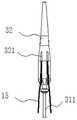
请参阅图3,输送装置300包括鞘管组件31、端头32和手柄组件33。端头32连接在鞘管组件31的远端,端头32为中空结构,其内腔与鞘管组件31的管腔相连通,一起作为导丝通道。手柄组件33连接在鞘管组件31的近端,用于控制鞘管组件31的各部件的轴向移动,使管腔支架100从输送装置300中释放。Referring to FIG. 3 , the
请参阅图4,鞘管组件31包括内芯管311、外芯管312、推管313、鞘管314和固定锚315。Referring to FIG. 4 , the
其中,端头32连接在内芯管311的远端,内芯管311的管腔与端头32的内腔相连通,一起作为导丝通道。外芯管312套在内芯管311外且可相对内芯管311轴向移动,固定锚315连接在外芯管312的远端,并跟随外芯管312一起轴向移动,端头32上设置有固定锚限位槽322,固定锚315可分离地连接在固定锚限位槽322内。推管313套在外芯管312外、并位于外芯管312与鞘管314之间,鞘管314套在推管313外且可相对推管313轴向移动,手柄组件33连接在鞘管314的近端。当鞘管314套在外芯管312外时,鞘管314与外芯管312之间形成一个环形腔体,压缩后的管腔支架100收容于该环形腔体内。请再次参阅图1,管腔支架100一端的裸支架101钩挂在固定锚315上,管腔支架100的另一端与推管313的远端端面相抵,使管腔支架100轴向压缩在固定锚315与推管313之间。由于管腔支架100整体被约束在鞘管314内,在到达病变位置前,管腔支架100与输送装置300可保持相对静止的状态,当装载有管腔支架100的输送装置300到达病变位置后,将管腔支架100释放。Wherein, the
手术时,首先,利用手柄组件33将鞘管314后撤,使管腔支架100从输送装置300中释放,此时在半释放装置200的约束下,管腔支架100处于半释放状态。其次,对管腔支架100的轴向和周向位置进行调整,待定位准确后,再将限位导丝21与束缚单元20分离,使半释放装置200的约束解除,从而使管腔支架100展开贴壁。然后,将外芯管312相对内芯管311后移,固定锚315跟随外芯管312一起后移,并逐渐与固定锚限位槽322分离,从而将裸支架101的约束解除,此时管腔支架100完全展开。最后,将输送装置300撤出体外,并通过导丝抓捕器(未示出)将分支10内的预置导丝15的一端抓到体外,利用预置导丝15建立从体外至分支10的血管通道,在分支10内套接延长支架。During the operation, firstly, the
在实际手术过程中,鞘管组件31的远端部分进入人体血管,其远端需要有足够的柔顺性,而鞘管组件31的近端需要提供足够的支撑力,以减小管腔支架释放时所需的推动力。故,请参阅图5,鞘管组件31还包括支撑件316,支撑件316位于推管313内,且支撑件316的长度不长于推管313的长度,该支撑件316可以为金属管等材质较硬的管件。在图5所示的实施例中,支撑件316为中空管状结构,其固定在推管313的内壁上,支撑件316的近端延伸至推管313的近端,支撑件316的远端延伸至推管313的远端,支撑件316可通过胶水粘接或热熔等方式固定在推管313内。可以理解的是,本实施例并不限定支撑件316的具体结构,例如,在其它实施例中,支撑件316为呈细条状的实心的金属件,其固定在推管313内壁上。In the actual operation process, the distal part of the
推管313内设置有分别沿轴向贯穿的管腔通道3131与导丝通道3132。支撑件316固定在管腔通道3131的内壁上,外芯管312从管腔通道3131内穿设,限位导丝21或/和预置导丝15从导丝通道3132中穿设。在图5所示的实施例中,导丝通道3132包括三个,三个导丝通道3132中的两个供预置导丝15穿设,另一个供限位导丝21穿设。The
其中,限位导丝21和/或预置导丝15可以为表面粗糙度较小、且与人体生物相容性较好的金属导丝,如镍钛丝等。为了不增大输送系统的整体轮廓尺寸,同时避免限位导丝21与预置导丝15受力弯折,限位导丝21与预置导丝15的丝径均为0.2mm~0.6mm。Wherein, the limiting
为了避免限位导丝21与预置导丝15的远端对血管造成损伤,限位导丝21与预置导丝15的近端段一般为较柔软的柔性段。但是,由于预置导丝15的近端段较柔软,在输送过程中,预置导丝15的近端段容易发生移位,若预置导丝15从裸支架101的波峰下方穿过裸支架101,当裸支架101展开贴壁后,会使预置导丝15挤压在裸支架101与血管壁之间,导致无法套接延长支架。In order to prevent the distal ends of the limiting
请参阅图6,端头32上设置有限位机构321,限位导丝21和/或预置导丝15的前端可分离地连接至该限位机构321,在外力作用下,导丝与限位机构321可分离。组装时,使限位导丝21和/或预置导丝15从管腔支架100的前端穿出,并使限位导丝21和/或预置导丝15的前端连接至该限位机构321,确保在输送过程中,限位导丝21和/或预置导丝15的前端始终连接在该限位机构321上。在图6所示的实施例中,限位机构321为限位槽,该限位槽沿端头32的轴向延伸至端头32的近端,限位导丝21和/或预置导丝15收容在该限位槽内、并与限位槽过盈配合,在外力作用下,导丝与限位槽可分离。可以理解的是,本实施例并不限定限位槽的具体结构,例如,在图7所示的实施例中,限位槽大致为U形槽,限位导丝21和/或预置导丝15的前端延伸至U形槽的弯曲段,避免导丝从限位槽中脱落,限位导丝21和/或预置导丝15与U形槽也可以过盈配合,进一步避免导丝从限位槽中脱落。Please refer to FIG. 6 , a
还可以理解的是,本实施例并不限定限位机构321的具体结构,只要确保限位导丝21和/或预置导丝15能被束缚在限位机构321上,且在外力作用下能使导丝与限位机构321脱离即可。例如,在其他实施例中,限位机构321为由两个弹片组成的夹持机构,两个弹片设置在端头上,导丝夹持在两个弹片之间,在外力作用下,使导丝从两个弹片中脱离。It can also be understood that this embodiment does not limit the specific structure of the limiting
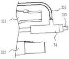
请再次参阅图3,手柄组件33包括固定手柄331、滑动手柄332、导杆333、锁止组件334、连通管335及接头组件336。Please refer to FIG. 3 again, the
其中,接头组件336连接至鞘管组件31的近端,连通管335连接在接头组件336上、并与鞘管组件31的内腔相连通。导杆333的近端与接头组件336固定连接,固定手柄331固定在导杆333的远端。滑动手柄332可滑动的连接在导杆333上,滑动手柄332与鞘管314固定连接,鞘管314跟随滑动手柄332一起沿轴向移动。锁止组件334分别与滑动手柄332及导杆333连接,用于控制滑动手柄332与导杆333之间沿轴向的相对移动。当锁止组件334处于锁定状态时,滑动手柄332与导杆333不可相对移动,当锁止组件334处于非锁定状态时,滑动手柄332与导杆333可相对移动。Wherein, the
在图3所示的实施例中,导杆333与滑动手柄332通过螺纹结构可滑动的连接。可以理解的是,本实施例并不限定导杆333与滑动手柄332间滑动连接的具体方式,只要能使二者相对滑动即可。例如,在其他实施例中,导杆333上设置有滑轨,滑动手柄332上设置有可滑动的连接在该滑轨内的滑块。In the embodiment shown in FIG. 3 , the
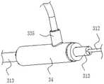
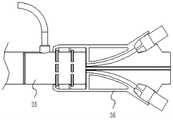
请参阅图8,接头组件包括推管接头34、导杆接头35及导丝接头36。导杆接头35连接在导杆333的近端,推管接头34固定在导管接头35内,导丝接头36固定在导杆接头35外。推管接头34固定在推管313外,推管313内的限位导丝及预置导丝分别通过导丝接头3352延伸至手柄组件33外。Please refer to FIG. 8 , the joint assembly includes a push tube joint 34 , a guide rod joint 35 and a guide wire joint 36 . The guide rod joint 35 is connected to the proximal end of the
请参阅图9,推管313内还设置有沿轴向分布的交换通道3133,交换通道3133与管腔通道3131及导丝通道3132相隔离、并与外界相连通。交换通道3133的远端延伸至推管313的远端,推管313上设置有使交换通道3133与外界连通的开口3134,操作者可通过交换通道3133向体内注入液体或气体等注入物,来保证输送系统的排水或排气功能。由于交换通道3133与管腔通道3131相互隔离,则交换通道3133与管腔通道3131内的支撑件316不会相互影响,在保证输送系统的排水或排气功能的同时,还可确保输送装置的近端具有足够的支撑力。Please refer to FIG. 9 , the
推管接头34大致为中空结构,其固定在推管313外,推管接头34上设置有与开口3134相连通的交换口341。请参阅图9和图10,连通管335的一端连接至推管接头34、并与交换口341相导通,另一端延伸至接头组件外。操作者可通过连通管335向交换通道3133内注入液体或气体等注入物。The push tube joint 34 is roughly hollow, and is fixed outside the
在图9所示的实施例中,推管接头34套设在推管313的近端外,交换通道3133沿轴向贯穿推管313的两端,开口3134设置在推管313的侧壁上,交换通道3133的近端填充有密封件343,避免注入物从推管313的近端流出,该密封件343可以为胶水或其他填充物。推管接头34上设置有与交换口341连通的环形凸台345,连通管335与该环形凸台345插接相连。为了使注入物平缓的进入交换通道3133,推管接头34的内壁设置有过渡槽342,过渡槽342位于开口3134与交换口341之间。为了避免注入物流入推管接头34与推管313之间的缝隙内,过渡槽342的槽口边缘与推管313之间填充有密封件343,该密封件343可以为胶水或其他填充物。为了方便加工,过渡槽342的近端延伸至推管接头34的近端,推管接头34的近端套设有压块344,压块344套设在过渡槽342与推管313之间用于密封过渡槽342与推管313,以避免注入物从过渡槽342的近端流出。In the embodiment shown in FIG. 9 , the
可以理解的是,本实施例并不限定开口3134在推管313上的具体位置,只要能使交换通道3133与连通管335相导通即可。例如,在其它实施例中,开口3134还可以位于推管313的近端端面上,此时连通管335可直接插设至该开口3134内。It can be understood that this embodiment does not limit the specific position of the
请参阅图11,推管接头34套设在导杆333的近端内,导杆333的侧壁上设置有连通管固定件3331,连通管335穿过该连通管固定件3331与推管接头34连接。在图12所示的实施例中,导杆333大致为圆筒结构,该圆筒结构由两个半圆形的连接筒拼接组成,两个连接筒可以通过粘接或卡扣连接等方式拼接在一起。连通管固定件3331为U形槽结构,其开设在两个连接筒的连接处,连通管固定件3331的近端延伸至导杆333的近端,当推管接头34装配在导杆333内时,连通管335的侧壁抵接至连通管固定件3331的远端。Please refer to Fig. 11, the push pipe joint 34 is sleeved in the proximal end of the
可以理解的是,本实施例并不限定连通管固定件3331的具体形状,只要能使连通管335穿过即可。例如,在其他实施例中,连通管固定件3331还可以为圆孔结构,连通管335穿过该连通管固定件3331与推管接头34上的交换口341连接。还可以理解的是,本实施例并不限定导杆333的具体结构,其还可以由多个连接筒拼接组成。It can be understood that, this embodiment does not limit the specific shape of the connecting
请再次参阅图11,导杆接头35大致为中空结构,其套设在导杆333外。导杆接头35上设置有连通管定位件351,连通管335从该连通管定位件351中穿设。Please refer to FIG. 11 again, the guide rod joint 35 is generally a hollow structure, which is sheathed outside the
在图11所示的实施例中,连通管定位件351为U形槽结构,其远端延伸至导杆接头35的远端,当导杆接头35装配在导杆333上时,连通管335的侧壁抵接至连通管定位件351的近端。可以理解的是,本实施例并不限定连通管定位件351的具体形状,只要能使连通管335穿过即可。例如,在其他实施例中,连通管定位件351还可以为圆孔结构。In the embodiment shown in FIG. 11 , the connecting
可以理解的是,由于连通管335连接在推管接头34上,若连通管335发生移位,则推管接头34及连接在推管接头34上的推管313会一起移位,不利于管腔支架的准确定位。本实施例通过使连通管335抵接至连通管定位件351的近端,并使连通管335抵接至连通管固定件3331的远端,可以对连通管335进行轴向定位,避免连通管335发生轴向移位。进一步的,为了避免连通管335的周向移位,连通管固定件3331或连通管定位件351沿周向的宽度与位于其间的连通管335的外径相同。It can be understood that since the connecting
由于导杆接头35套设在导杆333外,为了避免导杆接头35与导杆333发生相对移动,导杆接头35与导杆333之间设置有第一定位结构(未示出)。该第一定位结构可以包括设置在导杆接头35的内壁上的卡槽,以及设置在导杆333的外壁上的卡扣,当导杆接头35套设在导杆333外时,卡扣与卡槽扣合连接,避免导杆接头35与导杆333之间发生移位。可以理解的是,本实施例并不限定该第一定位结构的具体结构,只要能避免导杆接头35与导杆333发生相对移动即可。Since the guide rod joint 35 is sheathed outside the
请参阅图13,导杆接头35的内壁凸置有环形卡台352,推管313从推管接头34、环形卡台352中穿设,并延伸至导杆接头35的近端或其近端附近。当导杆接头35套设在推管接头34外时,推管接头34的近端抵接至该环形卡台352,该环形卡台352不仅可以限制推管接头34的轴向移动,还可以支撑推管313。Please refer to FIG. 13 , the inner wall of the guide rod joint 35 is protruded with an
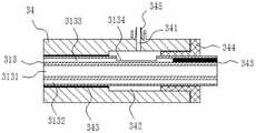
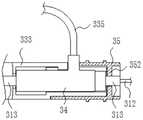
请参阅图14、图15和图16,导丝接头36大致为中空结构,其套设在导杆接头35外,推管313与导丝接头36的内腔相连通。导丝接头36上设置有多个与其内腔相连通的穿孔365,从推管313的近端伸出的导丝(预置导丝15或限位导丝21)及外芯管312分别通过对应的穿孔365延伸至导丝接头36外。Please refer to FIG. 14 , FIG. 15 and FIG. 16 , the guide wire joint 36 is generally hollow, and it is sheathed outside the guide rod joint 35 , and the
为了方便操作人员对导丝及外芯管312进行移位,导丝接头36是内表面设置有导丝限位槽361和芯管限位槽362,从推管313的近端伸出的导丝通过导丝限位槽361从对应的穿孔365中穿出,从推管313的近端伸出的外芯管312通过芯管限位槽362从对应的穿孔365中穿出。In order to facilitate the operator to displace the guide wire and the
在图14、图15和图16所示的实施例中,推管313的近端延伸至导丝接头36内,导丝接头36内设置有一个芯管限位槽362,以及两个导丝限位槽361,两个预置导丝15分别安装在对应的导丝限位槽361内。芯管限位槽362沿外芯管312的轴向分布,两个导丝限位槽361大致呈弧形、分设在内芯管限位槽362的两侧。导丝限位槽361的近端处设置有导丝锁紧装置367,当导丝锁紧装置367锁紧时,导丝固定在导丝接头36内,当导丝锁紧装置367解锁时,导丝可相对导丝接头36移动。In the embodiment shown in Fig. 14, Fig. 15 and Fig. 16, the proximal end of the
可以理解的是,导丝限位槽361的近端与远端之间的连线与推管313的纵向中心轴之间的夹角越大,导丝的推送阻力越大,不利于推进和拉出导丝,但是上述夹角越小,导丝越容易与导丝接头36近端侧的其他部件发生干涉。故,在本实施例中,当导丝接头36套设在导杆接头35外时,导丝限位槽361的近端与远端之间的连线与推管313的纵向中心轴之间的夹角为20°~40°。It can be understood that the greater the angle between the line between the proximal end and the distal end of the guide
还可以理解的是,由于导丝的硬度较低,若推管313的近端与导丝限位槽361的远端之间有间隙,则导丝在向前推进的过程中在该间隙处容易出现折弯,影响导丝的推进。故,在本实施例中,当导丝接头36套设在导杆接头35外时,推管313内的导丝通道3132的近端与导丝限位槽361的远端共轴线,推管313的近端端面与导丝限位槽361的远端端面位于同一平面内。It can also be understood that, due to the low hardness of the guide wire, if there is a gap between the proximal end of the
进一步的,导丝接头36与导杆接头35之间设置有第二定位结构,以避免导丝接头36与导杆接头35发生相对移动。Further, a second positioning structure is provided between the guide wire joint 36 and the guide rod joint 35 to avoid relative movement between the guide wire joint 36 and the guide rod joint 35 .
第二定位结构包括设置在导丝接头36的内壁上的第一定位槽363,以及设置在导杆接头35的外壁上、沿周向分布的第一定位筋353。当导丝接头36套设在导杆接头35外时,第一定位筋353卡持在第一定位槽363内,避免导丝接头36与导杆接头35发生轴向移动。第二定位结构还包括设置在导丝接头36的内壁上、沿轴向分布的第二定位筋364,以及设置在导杆接头35上的第二定位槽354,第二定位槽354为开设在第一定位筋353上的缺口。当导丝接头36套设在导杆接头35外时,第二定位筋364卡持在第二定位槽354内,避免导丝接头36与导杆接头35发生周向移动。组装时,只需将第二定位筋364插入第二定位槽354内,直至第一定位筋353卡持在第一定位槽363内,即可实现导丝接头36与导杆接头35的轴向和周向定位,操作简单,加工方便。可理解的是,本实施例并不限定第二定位结构的具体结构,只要能避免导丝接头36与导杆接头35发生相对移动即可。The second positioning structure includes a
请参阅图16、图17和图18,导丝接头36上还设置有导丝定位机构37,从导丝接头36的穿孔365中穿出的导丝(限位导丝21或预置导丝15)与导丝定位机构37固定连接,导丝定位机构37使导丝固定在导丝接头36上,避免导丝在输送过程中发生移位。Referring to Fig. 16, Fig. 17 and Fig. 18, a guide
在图18所示的实施例中,导丝接头36的外表面设置有容纳槽366,导丝定位机构37安装在容纳槽366内。导丝定位机构37包括拉扣组件371,以及对拉扣组件371进行限位的拉扣定位组件372,导丝固定在拉扣组件371上,拉扣组件371可拆卸的连接在拉扣定位组件372上。In the embodiment shown in FIG. 18 , the outer surface of the
拉扣组件371包括拉扣主体3711,及连接在拉扣主体3711上的拉环3712。限位导丝21从穿孔365中穿出后与拉扣主体3711固定连接,操作者的手指可伸入拉环3712内,将拉扣组件371从拉扣定位组件372中拉出。The
请参阅图18和图19,拉扣主体3711包括第一扣合部3713、连接部3714及第二扣合部3715。第一扣合部3713为平板状,其大致平行于容纳槽366的槽底平面。连接部3714的一端连接在第一扣合部3713上,另一端朝远离容纳槽366的一侧延伸,拉环3713固定在连接部3714的另一端,使拉环3713与容纳槽的槽底具有一定距离,方便操作者将手指伸入拉环3713内。第二扣合部3715的固定在连接部3714的另一端,并朝靠近容纳槽366的一侧延伸,第二扣合部3715为平板状,其大致沿垂直于容纳槽366的槽底方向延伸,第二扣合部3715上设置有卡槽结构。Please refer to FIG. 18 and FIG. 19 , the
拉扣定位组件372包括第一定位件3721和第二定位件3722。第一定位件3721大致为平板状,其固定在容纳槽366的侧壁上,第二定位件3722上设置有卡扣结构,其固定在容纳槽366的槽底。当拉扣组件371安装在容纳槽366内时,第一扣合部3713位于第一定位件3721的下方、并抵接至容纳槽366的侧壁,第二定位件3722的卡扣结构与第二扣合部3715上的卡槽结构扣合连接,从而使拉扣组件371被限制在导丝接头36上。The
进一步的,拉扣组件371还包括连接在拉扣主体3711上的固定槽374,及设在固定槽374内的固定件375。装配时,将限位导丝21固定在固定件375上,再将固定件375装配在固定槽374内,使固定件375固定安装在固定槽374内。由于导丝的丝径较小,不方便直接将导丝固定在拉扣组件371上,通过上述固定槽与固定件的结构,可以增加导丝与拉扣组件371的连接稳定性。Further, the
具体的,固定件375大致为圆柱体机构,固定件375的侧壁上设置有沿径向贯穿的第一导引通道3751,固定槽374的侧壁上设置有与第一导引通道3751相连通的第二导引通道3741。装配时,使导丝的近端穿过第一导引通道3751与第二导引通道3741,将导丝固定在固定件375上。Specifically, the fixing
可以理解的是,在其它实施例中,导丝接头36上还可以不设置容纳槽366,导丝定位机构37直接装配在导丝接头36的外壁。还可以理解的是,本实施例并不限定导丝定位机构37的具体结构,在其它实施例中,导丝定位机构37还可以为其他结构,只要能对导丝进行限位即可。It can be understood that, in other embodiments, the receiving
以上所述实施例的各技术特征可以进行任意的组合,为使描述简洁,未对上述实施例中的各个技术特征所有可能的组合都进行描述,然而,只要这些技术特征的组合不存在矛盾,都应当认为是本说明书记载的范围。The various technical features of the above-mentioned embodiments can be combined arbitrarily. To make the description concise, all possible combinations of the various technical features in the above-mentioned embodiments are not described. However, as long as there is no contradiction in the combination of these technical features, should be considered as within the scope of this specification.
以上所述实施例仅表达了本发明的几种实施方式,其描述较为具体和详细,但并不能因此而理解为对发明专利范围的限制。应当指出的是,对于本领域的普通技术人员来说,在不脱离本发明构思的前提下,还可以做出若干变形和改进,这些都属于本发明的保护范围。因此,本发明专利的保护范围应以所附权利要求为准。The above-mentioned embodiments only express several implementation modes of the present invention, and the descriptions thereof are relatively specific and detailed, but should not be construed as limiting the patent scope of the invention. It should be pointed out that those skilled in the art can make several modifications and improvements without departing from the concept of the present invention, and these all belong to the protection scope of the present invention. Therefore, the protection scope of the patent for the present invention should be based on the appended claims.
Claims (10)
Priority Applications (1)
| Application Number | Priority Date | Filing Date | Title |
|---|---|---|---|
| CN202210367158.7ACN115337132A (en) | 2018-12-27 | 2018-12-27 | Conveying Devices and Systems |
Applications Claiming Priority (2)
| Application Number | Priority Date | Filing Date | Title |
|---|---|---|---|
| CN202210367158.7ACN115337132A (en) | 2018-12-27 | 2018-12-27 | Conveying Devices and Systems |
| CN201811613310.5ACN109700564B (en) | 2018-12-27 | 2018-12-27 | Conveying device and system |
Related Parent Applications (1)
| Application Number | Title | Priority Date | Filing Date |
|---|---|---|---|
| CN201811613310.5ADivisionCN109700564B (en) | 2018-12-27 | 2018-12-27 | Conveying device and system |
Publications (1)
| Publication Number | Publication Date |
|---|---|
| CN115337132Atrue CN115337132A (en) | 2022-11-15 |
Family
ID=66257801
Family Applications (2)
| Application Number | Title | Priority Date | Filing Date |
|---|---|---|---|
| CN202210367158.7APendingCN115337132A (en) | 2018-12-27 | 2018-12-27 | Conveying Devices and Systems |
| CN201811613310.5AActiveCN109700564B (en) | 2018-12-27 | 2018-12-27 | Conveying device and system |
Family Applications After (1)
| Application Number | Title | Priority Date | Filing Date |
|---|---|---|---|
| CN201811613310.5AActiveCN109700564B (en) | 2018-12-27 | 2018-12-27 | Conveying device and system |
Country Status (1)
| Country | Link |
|---|---|
| CN (2) | CN115337132A (en) |
Cited By (1)
| Publication number | Priority date | Publication date | Assignee | Title |
|---|---|---|---|---|
| WO2024114366A1 (en)* | 2022-12-02 | 2024-06-06 | 先健科技(深圳)有限公司 | Delivery system |
Families Citing this family (5)
| Publication number | Priority date | Publication date | Assignee | Title |
|---|---|---|---|---|
| EP3903731A4 (en)* | 2018-12-27 | 2022-09-28 | Shenzhen Lifetech Endovascular Medical Co., Ltd. | DEVICE AND DISTRIBUTION SYSTEM |
| CN110974502B (en)* | 2019-11-14 | 2022-09-02 | 先健科技(深圳)有限公司 | Conveyor and implant conveying system |
| CN110934618B (en)* | 2019-12-17 | 2025-06-13 | 宁波迪创医疗科技有限公司 | A controlled release system |
| CN114681113A (en)* | 2020-12-29 | 2022-07-01 | 上海微创心脉医疗科技(集团)股份有限公司 | Covered stent system |
| CN118217045B (en)* | 2024-05-22 | 2024-10-15 | 北京心祐医疗科技有限公司 | Tectorial membrane support, tectorial membrane support conveyer and tectorial membrane support conveying system |
Citations (5)
| Publication number | Priority date | Publication date | Assignee | Title |
|---|---|---|---|---|
| CN101045022A (en)* | 2006-03-30 | 2007-10-03 | 温宁 | Self-expanding stent axial wire-drawing tensioning mechanism |
| US20080109065A1 (en)* | 2006-09-28 | 2008-05-08 | Med Institute, Inc. | Endovascular delivery device |
| CN102499801A (en)* | 2011-10-19 | 2012-06-20 | 微创医疗器械(上海)有限公司 | Delivery and release system of covered stent |
| CN108245290A (en)* | 2016-12-29 | 2018-07-06 | 先健科技(深圳)有限公司 | Transport system |
| CN108261252A (en)* | 2016-12-30 | 2018-07-10 | 先健科技(深圳)有限公司 | Intraluminal stent and transport system |
Family Cites Families (9)
| Publication number | Priority date | Publication date | Assignee | Title |
|---|---|---|---|---|
| US8500792B2 (en)* | 2003-09-03 | 2013-08-06 | Bolton Medical, Inc. | Dual capture device for stent graft delivery system and method for capturing a stent graft |
| CN101357088B (en)* | 2008-08-21 | 2011-09-28 | 上海交通大学 | Banding self-ejection type intervention apparatus conveying system |
| US8852259B2 (en)* | 2009-05-27 | 2014-10-07 | Katsuhiko Oka | Indwelling device for tubular medical treatment instrument and front tip of indwelling device for tubular medical treatment instrument |
| JP5564507B2 (en)* | 2009-08-03 | 2014-07-30 | テルモ株式会社 | Stent delivery system |
| CN102038565B (en)* | 2010-12-17 | 2013-08-14 | 北京有色金属研究总院 | Great vascular stent delivery system |
| CN102961198B (en)* | 2012-10-31 | 2015-06-10 | 普霖医疗科技(广州)有限公司 | Covered stent conveyor |
| US9439796B2 (en)* | 2013-03-15 | 2016-09-13 | Cook Medical Technologies Llc | Prosthesis delivery device |
| CN108236533B (en)* | 2016-12-26 | 2024-09-24 | 先健科技(深圳)有限公司 | Conveying system |
| CN109700565B (en)* | 2018-12-27 | 2021-07-20 | 深圳市先健畅通医疗有限公司 | Conveying device and system |
- 2018
- 2018-12-27CNCN202210367158.7Apatent/CN115337132A/enactivePending
- 2018-12-27CNCN201811613310.5Apatent/CN109700564B/enactiveActive
Patent Citations (5)
| Publication number | Priority date | Publication date | Assignee | Title |
|---|---|---|---|---|
| CN101045022A (en)* | 2006-03-30 | 2007-10-03 | 温宁 | Self-expanding stent axial wire-drawing tensioning mechanism |
| US20080109065A1 (en)* | 2006-09-28 | 2008-05-08 | Med Institute, Inc. | Endovascular delivery device |
| CN102499801A (en)* | 2011-10-19 | 2012-06-20 | 微创医疗器械(上海)有限公司 | Delivery and release system of covered stent |
| CN108245290A (en)* | 2016-12-29 | 2018-07-06 | 先健科技(深圳)有限公司 | Transport system |
| CN108261252A (en)* | 2016-12-30 | 2018-07-10 | 先健科技(深圳)有限公司 | Intraluminal stent and transport system |
Cited By (1)
| Publication number | Priority date | Publication date | Assignee | Title |
|---|---|---|---|---|
| WO2024114366A1 (en)* | 2022-12-02 | 2024-06-06 | 先健科技(深圳)有限公司 | Delivery system |
Also Published As
| Publication number | Publication date |
|---|---|
| CN109700564A (en) | 2019-05-03 |
| CN109700564B (en) | 2022-04-22 |
Similar Documents
| Publication | Publication Date | Title |
|---|---|---|
| CN109700565B (en) | Conveying device and system | |
| CN115337132A (en) | Conveying Devices and Systems | |
| WO2020134538A1 (en) | Delivery apparatus and system | |
| US8435249B2 (en) | Flexible connection catheter tunneler and methods for using the same | |
| CN109700566B (en) | Conveying device and system | |
| CN101040770B (en) | Intubation system for use with an endoscope | |
| US8623064B2 (en) | Stent graft delivery system and method of use | |
| US8709064B2 (en) | Introducer assembly and dilator tip therefor | |
| JP2019084371A (en) | Catheter assembly | |
| CN109908453B (en) | A device for assisting guide catheter through tortuous blood vessels | |
| EP1738793A1 (en) | Stent graft indwelling device and fixed chip | |
| US20080114435A1 (en) | Flexible delivery system | |
| WO2009064672A2 (en) | Device and method for stent graft fenestration in situ | |
| EP1266626B1 (en) | Tamping mechanism | |
| CN207071112U (en) | Induction system | |
| WO2023109315A1 (en) | Stent delivery device and stent delivery system | |
| JP5817181B2 (en) | Medical equipment | |
| JP6322374B2 (en) | Tube stent delivery device | |
| CN203619729U (en) | Stent conveying system and rear release component thereof | |
| CN108697518B (en) | stent delivery system | |
| CN117179979A (en) | Conveying device and conveying suite of TIPS tectorial membrane support | |
| CN111067589A (en) | Catheter tube | |
| EP4559503A2 (en) | Catheter assembly | |
| CN115670762B (en) | In-situ windowing instrument capable of puncturing covered stent vertically | |
| CN111110302B (en) | Conveyor system |
Legal Events
| Date | Code | Title | Description |
|---|---|---|---|
| PB01 | Publication | ||
| PB01 | Publication | ||
| SE01 | Entry into force of request for substantive examination | ||
| SE01 | Entry into force of request for substantive examination | ||
| TA01 | Transfer of patent application right | Effective date of registration:20221209 Address after:518063 8th floor, Xianjian technology building, No. 22, Keji South 12th Road, community, high tech Zone, Yuehai street, Nanshan District, Shenzhen, Guangdong Applicant after:LIFETECH SCIENTIFIC (SHENZHEN) Co.,Ltd. Address before:1607, Xianjian science and technology building, 22 Keji South 12 road, high tech community, Yuehai street, Nanshan District, Shenzhen, Guangdong 518052 Applicant before:Shenzhen Xianjian Changtong Medical Co.,Ltd. | |
| TA01 | Transfer of patent application right |