CN115337067B - Clamping mechanism and clamping device thereof - Google Patents
Clamping mechanism and clamping device thereofDownload PDFInfo
- Publication number
- CN115337067B CN115337067BCN202211269429.1ACN202211269429ACN115337067BCN 115337067 BCN115337067 BCN 115337067BCN 202211269429 ACN202211269429 ACN 202211269429ACN 115337067 BCN115337067 BCN 115337067B
- Authority
- CN
- China
- Prior art keywords
- firing
- main shaft
- state
- clip
- locking
- Prior art date
- Legal status (The legal status is an assumption and is not a legal conclusion. Google has not performed a legal analysis and makes no representation as to the accuracy of the status listed.)
- Active
Links
Images


Classifications
- A—HUMAN NECESSITIES
- A61—MEDICAL OR VETERINARY SCIENCE; HYGIENE
- A61B—DIAGNOSIS; SURGERY; IDENTIFICATION
- A61B17/00—Surgical instruments, devices or methods
- A61B17/12—Surgical instruments, devices or methods for ligaturing or otherwise compressing tubular parts of the body, e.g. blood vessels or umbilical cord
- A61B17/128—Surgical instruments, devices or methods for ligaturing or otherwise compressing tubular parts of the body, e.g. blood vessels or umbilical cord for applying or removing clamps or clips
- A61B17/1285—Surgical instruments, devices or methods for ligaturing or otherwise compressing tubular parts of the body, e.g. blood vessels or umbilical cord for applying or removing clamps or clips for minimally invasive surgery
- A—HUMAN NECESSITIES
- A61—MEDICAL OR VETERINARY SCIENCE; HYGIENE
- A61B—DIAGNOSIS; SURGERY; IDENTIFICATION
- A61B17/00—Surgical instruments, devices or methods
- A61B17/10—Surgical instruments, devices or methods for applying or removing wound clamps, e.g. containing only one clamp or staple; Wound clamp magazines
- A61B17/105—Wound clamp magazines
- A—HUMAN NECESSITIES
- A61—MEDICAL OR VETERINARY SCIENCE; HYGIENE
- A61B—DIAGNOSIS; SURGERY; IDENTIFICATION
- A61B17/00—Surgical instruments, devices or methods
- A61B2017/00367—Details of actuation of instruments, e.g. relations between pushing buttons, or the like, and activation of the tool, working tip, or the like
- A—HUMAN NECESSITIES
- A61—MEDICAL OR VETERINARY SCIENCE; HYGIENE
- A61B—DIAGNOSIS; SURGERY; IDENTIFICATION
- A61B17/00—Surgical instruments, devices or methods
- A61B2017/0046—Surgical instruments, devices or methods with a releasable handle; with handle and operating part separable
- A—HUMAN NECESSITIES
- A61—MEDICAL OR VETERINARY SCIENCE; HYGIENE
- A61B—DIAGNOSIS; SURGERY; IDENTIFICATION
- A61B17/00—Surgical instruments, devices or methods
- A61B17/12—Surgical instruments, devices or methods for ligaturing or otherwise compressing tubular parts of the body, e.g. blood vessels or umbilical cord
- A61B2017/12004—Surgical instruments, devices or methods for ligaturing or otherwise compressing tubular parts of the body, e.g. blood vessels or umbilical cord for haemostasis, for prevention of bleeding
- A—HUMAN NECESSITIES
- A61—MEDICAL OR VETERINARY SCIENCE; HYGIENE
- A61B—DIAGNOSIS; SURGERY; IDENTIFICATION
- A61B90/00—Instruments, implements or accessories specially adapted for surgery or diagnosis and not covered by any of the groups A61B1/00 - A61B50/00, e.g. for luxation treatment or for protecting wound edges
- A61B90/03—Automatic limiting or abutting means, e.g. for safety
- A61B2090/033—Abutting means, stops, e.g. abutting on tissue or skin
- A61B2090/034—Abutting means, stops, e.g. abutting on tissue or skin abutting on parts of the device itself
Landscapes
- Health & Medical Sciences (AREA)
- Surgery (AREA)
- Life Sciences & Earth Sciences (AREA)
- Heart & Thoracic Surgery (AREA)
- Molecular Biology (AREA)
- Veterinary Medicine (AREA)
- Engineering & Computer Science (AREA)
- Biomedical Technology (AREA)
- Public Health (AREA)
- Medical Informatics (AREA)
- Nuclear Medicine, Radiotherapy & Molecular Imaging (AREA)
- Animal Behavior & Ethology (AREA)
- General Health & Medical Sciences (AREA)
- Reproductive Health (AREA)
- Vascular Medicine (AREA)
- Surgical Instruments (AREA)
- Clamps And Clips (AREA)
- Mutual Connection Of Rods And Tubes (AREA)
Abstract
Description
Translated fromChinese技术领域technical field
本发明涉及医疗器械领域,尤其涉及一种施夹机构及其施夹装置。The invention relates to the field of medical instruments, in particular to a clip applying mechanism and a clip applying device thereof.
背景技术Background technique
在外科手术中,需要利用手术器械来闭合血管以避免血液由手术部位的切口流失。通常,施夹装置包括长杆状施夹机构和手柄组件。施夹机构可经由例如穿刺器的辅助工具深入到人体中。通过操作手柄组件可控制施夹机构将结扎夹(简称夹子)输送到位于施夹机构前端的端部执行器,然后闭合端部执行器,使夹子夹住血管。During surgery, it is necessary to close blood vessels with surgical instruments to prevent blood loss through the incision at the surgical site. Typically, a clip applier includes a long rod-shaped clip applicator and a handle assembly. The clip applier mechanism can penetrate deep into the human body via an auxiliary tool such as a piercer. By operating the handle assembly, the clip applier mechanism can be controlled to deliver the ligation clip (clips for short) to the end effector located at the front end of the clip applier mechanism, and then the end effector is closed to make the clip clamp the blood vessel.
发明内容Contents of the invention
本发明实施例提供一种施夹机构及其施夹装置。Embodiments of the present invention provide a clamping mechanism and a clamping device thereof.
根据本发明第一方面,提供一种施夹装置的施夹机构,包括:管体,包括相对的头端和末端;主轴,设置为靠近所述末端并且至少部分所述主轴位于所述管体中;夹仓组件,所述夹仓组件从所述管体中穿过并且包括:设置在所述管体中的夹仓和从所述头端穿出的端部执行器,所述夹仓构造为装有夹子;推夹组件,至少部分所述推夹组件设置在所述管体中,所述推夹组件构造为被所述主轴向所述头端推动以将所述夹仓中的夹子输送到所述端部执行器内;击发组件,至少部分所述击发组件位于所述管体中,所述击发组件构造为被所述主轴向所述头端推动以闭合所述端部执行器,使所述端部执行器内的所述夹子被击发;其中,所述施夹机构还包括:主轴连接件,与所述主轴连接;击发连接件,与所述击发组件连接;卡合机构,设置于所述主轴连接件和所述击发连接件之间;其中,所述卡合机构、所述击发连接件、所述主轴连接件和所述击发组件构造为:当所述夹子被击发后,所述主轴连接件通过所述卡合机构带动所述击发连接件背向所述头端移动,并且所述击发连接件带动所述击发组件同方向移动,以使所述端部执行器被部分打开。According to the first aspect of the present invention, there is provided a clamping mechanism of a clamping device, comprising: a pipe body, including an opposite head end and an end; In; the clip bin assembly, the clip bin assembly passes through the tube body and includes: a clip bin set in the tube body and an end effector passing through the head end, the clip bin It is configured to be equipped with a clip; a push clip assembly, at least part of which is disposed in the tubular body, and the push clip assembly is configured to be pushed toward the head end by the main shaft to push the clip in the clip chamber. The clip of the end effector is delivered into the end effector; a firing assembly, at least part of which is located in the tubular body, is configured to be pushed toward the head end by the spindle to close the end an end effector, so that the clip in the end effector is fired; wherein, the clip applier mechanism further includes: a main shaft connection part, connected with the main shaft; a firing connection part, connected with the firing assembly; The engaging mechanism is arranged between the main shaft connecting piece and the firing connecting piece; wherein, the engaging mechanism, the firing connecting piece, the main shaft connecting piece and the firing assembly are configured as follows: when the After the clip is fired, the main shaft connecting piece drives the firing connecting piece to move away from the head end through the engaging mechanism, and the firing connecting piece drives the firing assembly to move in the same direction, so that the end The external actuator is partially opened.
至少一些实施例中,所述卡合机构包括:第一卡合件,设置于所述主轴连接件上;第二卡合件,设置于所述击发连接件上;其中,所述卡合机构具有释放状态和锁定状态;在所述释放状态下,所述第一卡合件位于所述第二卡合件中并且能从所述第二卡合件中移出;在所述锁定状态下,所述第一卡合件和所述第二卡合件彼此锁定。In at least some embodiments, the engaging mechanism includes: a first engaging member disposed on the spindle connecting member; a second engaging member disposed on the firing connecting member; wherein, the engaging mechanism It has a released state and a locked state; in the released state, the first engaging member is located in the second engaging member and can be removed from the second engaging member; in the locked state, The first engaging part and the second engaging part are locked to each other.
至少一些实施例中,所述施夹机构具有击发完成状态和后退状态;在所述击发完成状态下,所述端部执行器内的所述夹子被击发;在所述后退状态下,所述端部执行器内没有夹子,所述主轴连接件被施加外力以后退;其中,所述卡合机构构造为:当所述施夹机构处于所述击发完成状态或所述后退状态时,所述卡合机构处于所述锁定状态。In at least some embodiments, the clip applier mechanism has a fired completed state and a retracted state; in the fired completed state, the clip in the end effector is fired; in the retracted state, the There is no clip in the end effector, and the main shaft connector is retracted after being applied with an external force; wherein, the engaging mechanism is configured to: when the clip applying mechanism is in the firing completion state or the retreating state, the The engaging mechanism is in the locked state.
至少一些实施例中,所述施夹机构具有送夹完成状态和回转状态,在所述送夹完成状态下,所述夹子已被输送到所述端部执行器内; 其中,所述卡合机构构造为:当所述施夹机构处于所述送夹完成状态或所述回转状态时,所述卡合机构处于所述释放状态。In at least some embodiments, the clip applying mechanism has a clip feeding completed state and a rotating state, and in the clip feeding completed state, the clip has been delivered into the end effector; wherein, the engaging The mechanism is configured as follows: when the clip applying mechanism is in the clip feeding completion state or the rotation state, the engaging mechanism is in the release state.
至少一些实施例中,所述卡合机构还具有分离状态,在所述分离状态下,所述第一卡合件和所述第二卡合件彼此分离并且所述第一卡合件位于所述第二卡合件之外。In at least some embodiments, the engaging mechanism also has a disengaged state, and in the disengaged state, the first engaging member and the second engaging member are separated from each other and the first engaging member is located at the Except for the second engaging part mentioned above.
至少一些实施例中,所述施夹机构还具有初始状态,在所述初始状态下,所述主轴和所述主轴连接件均没有被施加外力;其中,所述卡合机构构造为:当所述施夹机构处于所述初始状态时,所述卡合机构处于所述分离状态。In at least some embodiments, the clamping mechanism also has an initial state, and in the initial state, no external force is applied to the main shaft and the main shaft connecting member; wherein, the engaging mechanism is configured as: When the clamping mechanism is in the initial state, the engaging mechanism is in the separated state.
至少一些实施例中,所述第一卡合件包括卡销,所述第二卡合件包括卡槽,所述卡槽包括释放位置和锁定位置,所述卡销构造为能在所述释放位置和所述锁定位置之间移动;其中,所述卡槽和所述卡销构造为:当所述卡合机构处于所述锁定状态时,所述卡销位于所述锁定位置;当所述卡合机构处于所述释放状态时,所述卡销位于所述释放位置并且能从所述卡槽中移出;当所述卡合机构处于分离状态时,所述卡销位于所述卡槽之外。In at least some embodiments, the first engaging member includes a bayonet pin, the second engaging member includes a bayonet groove, the bayonet groove includes a release position and a locking position, and the bayonet pin is configured to be able to position and the locking position; wherein, the locking groove and the locking pin are configured such that: when the locking mechanism is in the locking state, the locking pin is in the locking position; When the engaging mechanism is in the release state, the bayonet pin is located at the release position and can be removed from the bayonet slot; when the bayonet mechanism is in the disengaged state, the bayonet pin is located between the bayonet slots outside.
至少一些实施例中,所述击发连接件为管状件,所述卡槽为设置在所述管状件上的通槽,所述卡槽的槽口朝背向所述头端的方向敞开,所述释放位置位于所述卡槽的槽底。In at least some embodiments, the firing link is a tubular member, the slot is a through slot provided on the tubular member, the notch of the slot opens in a direction away from the head end, the The release position is located at the bottom of the card slot.
至少一些实施例中,所述击发组件包括:击发套管和至少部分位于所述击发套管中的击发杆体,所述击发杆体与所述击发连接件连接并且构造为被所述击发连接件带动以背向所述头端移动;所述击发套管用作所述管体,所述击发套管构造为被所述击发杆体带动以背向所述头端移动,以使所述端部执行器被部分开。In at least some embodiments, the firing assembly includes: a firing sleeve and a firing rod at least partially located in the firing sleeve, the firing rod is connected to the firing connection and is configured to be driven by the firing connection to move away from the head end; the firing sleeve is used as the tubular body, and the firing sleeve is configured to be driven by the firing rod body to move away from the head end so that the end effector are partly separated.
至少一些实施例中,所述施夹机构还包括:轴向卡合机构,设置在所述击发连接件和所述击发杆体之间,其中,所述击发连接件和所述击发杆体构造为通过所述轴向卡合机构在所述击发连接件的轴向方向上相互卡合,但在所述击发连接件的周向方向上能做相对运动。In at least some embodiments, the clamping mechanism further includes: an axial engagement mechanism disposed between the firing connection piece and the firing rod body, wherein the firing connection piece and the firing rod body are configured to pass through The axial engaging mechanisms engage with each other in the axial direction of the firing link, but are capable of relative movement in the circumferential direction of the firing link.
至少一些实施例中,所述轴向卡合机构包括:设置于所述击发杆体上的卡槽;和设置于所述击发连接件上的卡扣,所述卡扣构造为沿所述击发连接件的周向方向在所述卡槽中移动。In at least some embodiments, the axial locking mechanism includes: a slot provided on the firing rod body; and a buckle provided on the firing link, and the buckle is configured to move along the firing connection. The circumferential direction of the piece moves in the slot.
至少一些实施例中,所述卡槽为沿所述击发连接件的周向方向延伸的环形凹槽。In at least some embodiments, the locking groove is an annular groove extending along the circumferential direction of the firing link.
至少一些实施例中,所述施夹机构还包括:壳体,所述击发连接件位于所述壳体中;周向卡合机构,设置在所述击发连接件和所述壳体之间,其中所述击发连接件和所述壳体构造为通过所述周向卡合机构在所述主轴的周向方向上相互卡合,但在所述主轴的轴向方向上能做相对运动。In at least some embodiments, the clip applying mechanism further includes: a casing, the firing connection is located in the casing; a circumferential locking mechanism is arranged between the firing connection and the casing, Wherein the firing link and the casing are configured to engage with each other in the circumferential direction of the main shaft through the circumferential engaging mechanism, but can move relative to each other in the axial direction of the main shaft.
至少一些实施例中,所述壳体在所述管体的轴向方向上包括:第一壳体部和与所述第一壳体部连接的第二壳体部,所述第一壳体部靠近所述头端,所述第二壳体部远离所述头端,所述第一壳体部构造为能相对所述第二壳体部在所述主轴的周向方向旋转;所述周向卡合机构包括:设置在所述第二壳体部上的卡扣和设置在所述击发连接件上的卡槽,所述卡扣和所述卡槽构造为相互卡合。In at least some embodiments, the housing includes: a first housing part and a second housing part connected to the first housing part in the axial direction of the tubular body, the first housing The first housing part is close to the head end, the second housing part is away from the head end, and the first housing part is configured to be able to rotate in the circumferential direction of the main shaft relative to the second housing part; The circumferential locking mechanism includes: a buckle provided on the second housing part and a slot provided on the firing link, and the buckle and the slot are configured to engage with each other.
至少一些实施例中,所述卡扣为多个,所述卡槽为多个,所述多个卡扣和所述多个卡槽构造为一一对应设置且相互卡合。In at least some embodiments, there are multiple buckles and multiple slots, and the multiple buckles and the multiple slots are configured in a one-to-one correspondence and engaged with each other.
至少一些实施例中,所述卡合机构为多个,所述多个卡合机构沿所述主轴连接件的周向方向等间距地设置在所述主轴连接件和所述击发连接件之间。In at least some embodiments, there are multiple engaging mechanisms, and the plurality of engaging mechanisms are arranged at equal intervals along the circumferential direction of the main shaft connecting member between the main shaft connecting member and the firing connecting member. .
至少一些实施例中,所述主轴连接件为管状件,所述多个卡合机构包括两个卡合机构,所述两个卡合机构在所述管状件的径向方向上对称设置。In at least some embodiments, the main shaft connecting member is a tubular member, and the plurality of engaging mechanisms include two engaging mechanisms, and the two engaging mechanisms are arranged symmetrically in a radial direction of the tubular member.
根据本发明第二方面,提供一种包括上述施夹机构的施夹装置。According to a second aspect of the present invention, there is provided a clamping device comprising the above-mentioned clamping mechanism.
附图说明Description of drawings
为了更清楚地说明本发明实施例的技术方案,下面将对实施例的附图作简单地介绍,显而易见地,下面描述中的附图仅仅涉及本发明的一些实施例,而非对本发明的限制。In order to more clearly illustrate the technical solutions of the embodiments of the present invention, the following will briefly introduce the accompanying drawings of the embodiments. Obviously, the accompanying drawings in the following description only relate to some embodiments of the present invention, rather than limiting the present invention .
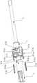
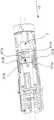
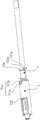
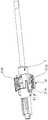
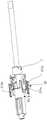
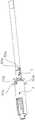
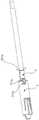
图1A和图1B分别为本发明实施例的施夹装置的两个状态示意图。FIG. 1A and FIG. 1B are schematic diagrams of two states of the clip applier according to the embodiment of the present invention, respectively.
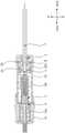
图2为本发明实施例的施夹机构的爆炸示意图。Fig. 2 is an exploded schematic view of the clamping mechanism of the embodiment of the present invention.
图3为本发明实施例的施夹机构处于初始状态A下的结构示意图。FIG. 3 is a schematic structural view of the clamping mechanism in an initial state A according to an embodiment of the present invention.
图3A为本发明实施例的施夹机构处于初始状态A下的局部结构示意图一。FIG. 3A is a schematic diagram of a partial structure of the clamping mechanism in an initial state A according to an embodiment of the present invention.
图3B为本发明实施例的施夹机构处于初始状态A下的局部结构示意图二。FIG. 3B is a second schematic diagram of the partial structure of the clamping mechanism in the initial state A according to the embodiment of the present invention.
图3C为本发明实施例的施夹机构处于初始状态A下的局部结构示意图三。FIG. 3C is a third schematic diagram of the partial structure of the clamping mechanism in the initial state A according to the embodiment of the present invention.
图3D为本发明实施例的施夹机构处于初始状态A下的剖面示意图。3D is a schematic cross-sectional view of the clamping mechanism in an initial state A according to an embodiment of the present invention.
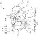
图4A为本发明实施例的主轴连接件的结构示意图一。FIG. 4A is a first schematic diagram of the structure of the main shaft connector according to the embodiment of the present invention.
图4B为本发明实施例的主轴连接件的局部结构示意图。Fig. 4B is a schematic diagram of a partial structure of the main shaft connector according to the embodiment of the present invention.
图4C为本发明实施例的主轴连接件的结构示意图二。FIG. 4C is a second structural schematic diagram of the main shaft connector according to the embodiment of the present invention.
图4D为本发明实施例的主轴连接件的结构示意图三。FIG. 4D is a third schematic structural view of the main shaft connector according to the embodiment of the present invention.
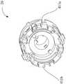
图5为本发明实施例的第二壳体部的局部结构示意图。Fig. 5 is a schematic diagram of a partial structure of the second casing part according to the embodiment of the present invention.
图6为本发明实施例的施夹机构处于送夹完成状态B下的局部结构示意图。FIG. 6 is a schematic diagram of the local structure of the clip applier mechanism in the state B of clip feeding completion according to the embodiment of the present invention.
图7A为本发明实施例的施夹机构处于调节状态C下的局部结构示意图一。FIG. 7A is a first schematic diagram of the partial structure of the clamping mechanism in the adjusted state C according to the embodiment of the present invention.
图7B为本发明实施例的施夹机构处于调节状态C下的局部结构示意图二。FIG. 7B is a second schematic diagram of the partial structure of the clamping mechanism in the adjusted state C according to the embodiment of the present invention.
图7C为本发明实施例的施夹机构处于调节状态C下的局部结构示意图三。FIG. 7C is a third schematic diagram of the partial structure of the clamping mechanism in the adjustment state C according to the embodiment of the present invention.
图8A为本发明实施例的施夹机构处于击发完成状态D下的结构示意图一。FIG. 8A is a first schematic structural view of the clip applier mechanism in the firing completion state D according to the embodiment of the present invention.
图8B为本发明实施例的施夹机构处于击发完成状态D下的结构示意图二。FIG. 8B is a second structural schematic diagram of the clip applier mechanism in the firing completion state D according to the embodiment of the present invention.
图8C为本发明实施例的施夹机构处于击发完成状态D下的结构示意图三。FIG. 8C is a third schematic structural view of the clip applier mechanism in the firing completion state D according to the embodiment of the present invention.
图9A为本发明实施例的施夹机构处于后退状态E下的结构示意图一。FIG. 9A is a structural schematic diagram 1 of the clip applier mechanism in the backward state E according to the embodiment of the present invention.
图9B为本发明实施例的施夹机构处于后退状态E下的结构示意图二。FIG. 9B is a second structural schematic diagram of the clip applier mechanism in the backward state E according to the embodiment of the present invention.
图9C为本发明实施例的施夹机构处于后退状态E下的结构示意图三。FIG. 9C is a third schematic structural view of the clamping mechanism in the backward state E according to the embodiment of the present invention.
图10A为本发明实施例的施夹机构处于回转状态F下的结构示意图一。FIG. 10A is a first schematic structural view of the clamping mechanism in a rotating state F according to an embodiment of the present invention.
图10B为本发明实施例的施夹机构处于回转状态F下的结构示意图二。FIG. 10B is a second schematic structural view of the clip applier mechanism in the rotating state F according to the embodiment of the present invention.
图10C为本发明实施例的施夹机构处于回转状态F下的结构示意图三。FIG. 10C is a third schematic structural view of the clamping mechanism in a rotating state F according to an embodiment of the present invention.
图10D为图10C的卡合机构的局部放大结构示意图。FIG. 10D is a partially enlarged structural schematic diagram of the engaging mechanism of FIG. 10C .
图11为本发明实施例的击发连接件的结构示意图。Fig. 11 is a schematic structural view of the firing link according to the embodiment of the present invention.
图12为本发明实施例的施夹机构的局部结构示意图。Fig. 12 is a schematic diagram of a partial structure of the clamping mechanism of the embodiment of the present invention.
图13为本发明实施例的卡合机构的结构示意图。Fig. 13 is a schematic structural diagram of the engaging mechanism of the embodiment of the present invention.
具体实施方式detailed description
为使本发明实施例的目的、技术方案和优点更加清楚,下面将结合本发明实施例的附图,对本发明实施例的技术方案进行清楚、完整地描述。显然,所描述的实施例是本发明的一部分实施例,而不是全部的实施例。基于所描述的本发明的实施例,本领域普通技术人员在无需创造性劳动的前提下所获得的所有其他实施例,都属于本发明保护的范围。In order to make the purpose, technical solutions and advantages of the embodiments of the present invention more clear, the following will clearly and completely describe the technical solutions of the embodiments of the present invention in conjunction with the drawings of the embodiments of the present invention. Apparently, the described embodiments are some, not all, embodiments of the present invention. Based on the described embodiments of the present invention, all other embodiments obtained by persons of ordinary skill in the art without creative efforts shall fall within the protection scope of the present invention.
除非另作定义,此处使用的技术术语或者科学术语应当为本发明所属领域内具有一般技能的人士所理解的通常意义。本发明专利申请说明书以及权利要求书中使用的“第一”、“第二”以及类似的词语并不表示任何顺序、数量或者重要性,而只是用来区分不同的组成部分。“包括”或者“包含”等类似的词语意指出现在“包括”或者“包含”前面的元件或者物件涵盖出现在“包括”或者“包含”后面列举的元件或者物件及其等同,并不排除其他元件或者物件。“连接”或者“相连”等类似的词语并非限定于物理的或者机械的连接,而是可以包括电性的连接,不管是直接的还是间接的。“上”、“下”、“左”、“右”等仅用于表示相对位置关系,当被描述对象的绝对位置改变后,则所述相对位置关系也可能相应地改变。Unless otherwise defined, the technical terms or scientific terms used herein shall have the usual meanings understood by those skilled in the art to which the present invention belongs. "First", "second" and similar words used in the patent application specification and claims of the present invention do not indicate any order, quantity or importance, but are only used to distinguish different components. Words such as "comprises" or "comprising" and similar terms mean that the elements or items listed before "comprising" or "comprising" include the elements or items listed after "comprising" or "comprising" and their equivalents, and do not exclude other component or object. Words such as "connected" or "connected" are not limited to physical or mechanical connections, but may include electrical connections, whether direct or indirect. "Up", "Down", "Left", "Right" and so on are only used to indicate relative positional relationship. When the absolute position of the described object changes, the relative positional relationship may also change accordingly.
在将夹子夹住血管之前,需要先将夹子输送到位于施夹机构前端的端部执行器内,然后通过操作手柄组件来击发夹子。在夹子已经被输送到端部执行器内的情况下,如果操作者发现夹子不合适(例如夹子尺寸或材料等),则需要将整个施夹机构从手柄组件上拆下来,再安装上带有合适夹子的另一施夹机构。在施夹装置的使用过程中,夹子的尺寸可能随时需要调整,因此,被更换下来的施夹机构有可能被再次安装使用。由于被更换下来的施夹机构的端部执行器内已有夹子,当该施夹机构再次被安装到手柄组件时,手柄组件无法识别出在端部执行器内已存在夹子,此时,再把另一夹子输送到端部执行器内,会损坏端部执行器,从而使施夹机构无法二次使用。Before clamping the clip to the blood vessel, the clip needs to be delivered to the end effector located at the front end of the clip applying mechanism, and then the clip is fired by operating the handle assembly. In the case that the clip has been delivered into the end effector, if the operator finds that the clip is not suitable (such as clip size or material, etc.), the entire clip application mechanism needs to be removed from the handle assembly, and then installed with Alternative clip-applying mechanism for suitable clips. During the use of the clamping device, the size of the clip may need to be adjusted at any time, therefore, the replaced clamping mechanism may be installed and used again. Since there are already clips in the end effector of the clip applier mechanism that has been replaced, when the clip applier mechanism is installed on the handle assembly again, the handle assembly cannot recognize that there are already clips in the end effector. Delivering another clip into the end effector would damage the end effector, rendering the clip applier mechanism unusable for re-use.
为此,本发明实施例提供一种施夹装置的施夹机构和包括该施夹机构的施夹装置,其目的至少在于避免在更换施夹机构时损坏端部执行器。To this end, embodiments of the present invention provide a clamping mechanism of a clipping device and a clipping device including the clipping mechanism, the purpose of which is at least to avoid damage to the end effector when replacing the clipping mechanism.
例如,本发明实施例提供的施夹装置的施夹机构包括:管体、主轴、夹仓组件、推夹组件。所述管体包括相对的头端和末端;所述主轴设置为靠近末端并且至少部分所述主轴设置在所述管体中;所述夹仓组件从所述管体中穿过并且包括设置在所述管体中的夹仓和从所述头端穿出的端部执行器,所述夹仓构造为装有夹子;至少部分所述推夹组件设置在所述管体中,所述推夹组件构造为被所述主轴向所述头端推动以将所述夹仓中的夹子输送到所述端部执行器内。进一步地,所述施夹机构还包括:主轴连接件、壳体和锁定机构。所述主轴连接件套设于所述主轴并且与所述主轴连接,所述主轴连接件构造为与所述主轴在管体的轴向方向上同方向移动;所述壳体构造为容纳所述主轴以及所述主轴连接件;所述锁定机构设置在所述主轴连接件和所述壳体之间。所述锁定机构、所述主轴连接件和所述壳体构造为:当所述夹子被输送到所述端部执行器内时,所述主轴连接件与所述壳体通过所述锁定机构彼此锁定。For example, the clamping mechanism of the clamping device provided in the embodiment of the present invention includes: a pipe body, a main shaft, a clamping chamber assembly, and a push clamping assembly. The tubular body includes opposing head and terminal ends; the main shaft is disposed proximate to the distal end and at least part of the main shaft is disposed in the tubular body; the cartridge assembly passes through the tubular body and includes a a clip bin in the tubular body and an end effector passing through the head end, the clip bin is configured to house a clip; at least part of the push clip assembly is disposed in the tubular body, the push clip A clip assembly is configured to be urged toward the head end by the spindle to deliver clips in the clip magazine into the end effector. Further, the clamping mechanism further includes: a main shaft connector, a housing and a locking mechanism. The main shaft connecting piece is sleeved on the main shaft and connected with the main shaft, the main shaft connecting piece is configured to move in the same direction as the main shaft in the axial direction of the pipe body; the housing is configured to accommodate the The main shaft and the main shaft connecting part; the locking mechanism is arranged between the main shaft connecting part and the housing. The locking mechanism, the spindle connection, and the housing are configured such that when the clip is delivered into the end effector, the spindle connection and the housing are mutually connected by the locking mechanism. locking.
上述本发明实施例提供的施夹机构中,通过设置与主轴连接的主轴连接件以及在主轴连接件和壳体之间设置锁定机构,可保证在夹子被输送到端部执行器内时,主轴连接件与壳体通过所述锁定机构被锁定。这样,当上述施夹机构被拆下来后,由于主轴连接件和主轴相对壳体的位置被锁定,无法在管体的轴向方向上移动,在二次使用施夹机构时,可避免下一个夹子被输送到端部执行器中,避免端部执行器被损坏,从而有利于施夹机构的长期使用。In the clamping mechanism provided by the above-mentioned embodiments of the present invention, by setting the main shaft connecting piece connected with the main shaft and setting the locking mechanism between the main shaft connecting piece and the housing, it can be ensured that when the clip is transported into the end effector, the main shaft The connecting piece and the housing are locked by the locking mechanism. In this way, when the above-mentioned clamping mechanism is disassembled, since the main shaft connector and the position of the main shaft relative to the housing are locked, they cannot move in the axial direction of the pipe body. When the clamping mechanism is used for the second time, the next clamping mechanism can be avoided. The clip is delivered into the end effector, which prevents the end effector from being damaged, thereby facilitating the long-term use of the clip applier mechanism.
下面通过几个具体的实施例对本发明进行说明。为了保持本发明实施例以下的说明清楚且简明,可省略已知功能和已知部件的详细说明。当本发明实施例的任一部件在一个以上的附图中出现时,该部件在每个附图中可以由相同的参考标号表示。The present invention will be described below through several specific examples. To keep the following description of the embodiments of the present invention clear and concise, detailed descriptions of known functions and known components may be omitted. When any component of the embodiment of the present invention appears in more than one drawing, the component may be represented by the same reference numeral in each drawing.
图1A和图1B分别为本发明实施例的施夹装置的两个状态示意图。图2为本发明实施例的施夹机构的爆炸示意图。图3为本发明实施例的施夹机构处于初始状态下的结构示意图。图3A为本发明实施例的施夹机构处于初始状态下的局部结构示意图一。图3B为本发明实施例的施夹机构处于初始状态下的局部结构示意图二。图3C为本发明实施例的施夹机构处于初始状态下的局部结构示意图三。FIG. 1A and FIG. 1B are schematic diagrams of two states of the clip applier according to the embodiment of the present invention, respectively. Fig. 2 is an exploded schematic view of the clamping mechanism of the embodiment of the present invention. Fig. 3 is a structural schematic diagram of the clamping mechanism in an initial state according to an embodiment of the present invention. FIG. 3A is a schematic diagram of a partial structure of the clamping mechanism in an initial state according to an embodiment of the present invention. FIG. 3B is a second schematic diagram of the partial structure of the clamping mechanism in the initial state according to the embodiment of the present invention. FIG. 3C is a third schematic diagram of the partial structure of the clamping mechanism in the initial state according to the embodiment of the present invention.
如图1A和图1B所示,本发明实施例提供的施夹装置900包括施夹机构91和手柄组件92。例如,施夹机构91可拆卸地连接于手柄组件92。当操作施夹装置900时,操作者可根据实际需要,从手柄组件92上快速拆卸或安装施夹机构91。As shown in FIG. 1A and FIG. 1B , a
手柄组件92构造为驱动施夹机构91以控制施夹机构执行各个动作,包括但不限于输送夹子、击发夹子、复位击发组件、复位推夹组件等。The
如图1B所示,施夹机构91包括管体90,并且管体90包括相对的头端90A和末端90B。也就是,在管体90的轴向方向Z上,头端90A与末端90B相对,头端90A为远离手柄组件92或者操作者的远端,末端90B为靠近手柄组件92或者操作者的近端。As shown in FIG. 1B , the
本发明实施例中,将管体90的延伸方向定义为轴向方向Z,如图1B所示,该轴向方向Z包括指向头端90A的+Z方向和背向头端90A的-Z方向。例如,本发明实施例中,当某部件或组件向头端90A移动时,可以理解为其沿+Z方向移动;当某部件或组件背向头端90A移动时,可以理解为其沿-Z方向移动。In the embodiment of the present invention, the extension direction of the
本发明实施例中,管体90的周向方向指管体90绕其旋转轴90X旋转时的方向,如图1B所示,该周向方向R包括方向相反的第一旋转方向+R和第二旋转方向-R。例如,从头端90A向末端90B看,第一旋转方向+R为逆时针方向,第二旋转方向-R为顺时针方向。In the embodiment of the present invention, the circumferential direction of the
如图2和图3A所示,施夹机构91包括主轴1、主轴连接件2、击发连接件3、夹仓组件、推夹组件、击发组件、壳体6、推杆7、端盖12。击发组件例如包括击发杆体4和击发套管5。夹仓组件例如包括夹仓9和夹钳11(也称端部执行器)。推夹组件例如包括推块8和推夹片10。As shown in FIG. 2 and FIG. 3A , the
至少一些实施例中,管体90具有空腔,主轴1、夹仓组件、推夹组件和击发组件的至少一部分设置在管体90中。In at least some embodiments, the
例如,主轴1设置为靠近管体90的末端90B并且至少部分主轴1设置在管体90中。例如,主轴1包括相对的第一端部1A和第二端部1B,在轴向方向Z上,第一端部1A靠近头端90A,第二端部1B远离头端90A。在施夹机构工作过程中,第一端部1A可位于管体90中。For example, the
例如,夹仓组件从管体90中穿过。夹仓9设置在管体90中,用于装载多个夹子。夹钳11从头端90A穿出。在一个示例中,多个夹子沿轴向方向Z排列在夹仓9中。For example, the cartridge assembly passes through the
例如,至少部分推夹组件设置在管体90中,推夹组件构造为被主轴1向头端90A推动以将夹仓9中的夹子输送到夹钳11内。在一个示例中,推块8可向头端90A移动,并且带动推夹片10以将夹仓9中的夹子依次推到夹钳11中。For example, at least part of the push-clip assembly is disposed in the
例如,至少部分所述击发组件位于管体90中,击发组件构造为被主轴1向头端90A推动以闭合夹钳11,使所述夹钳11内的夹子被击发。For example, at least part of the firing assembly is located in the
例如,击发套管5用作管体90,夹钳11从击发套管5的头端穿出。当击发套管5沿+Z方向移动时,击发套管5使夹钳11的两个钳臂朝彼此靠近的方向移动,以使夹钳11处于闭合状态,此时夹子被击发。当击发套管5沿-Z方向移动时,夹钳11的两个钳臂朝彼此远离的方向移动,以使夹钳11处于打开状态,等待后续送夹。For example, the firing
如图3B和图3C所示,主轴连接件2套设于主轴1并且与主轴1连接,主轴连接件2构造为与主轴1在轴向方向Z上同方向移动。例如,主轴连接件2套设于主轴1的第二端部1B并且连接于第二端部1B,当主轴1沿+Z或-Z方向移动时,主轴连接件2也随着主轴1一起沿+Z或-Z方向移动。As shown in FIG. 3B and FIG. 3C , the main
如图3B和图3C所示,例如,施夹机构91还包括轴向卡合机构22,设置于主轴1和主轴连接件2之间。在一个示例中,轴向卡合机构22包括设置于主轴1上的卡槽221和设置于主轴连接件2上的卡销222a、222b,卡销222a、222b构造为沿主轴1的周向方向在卡槽221中移动。As shown in FIG. 3B and FIG. 3C , for example, the
这样,通过设置轴向卡合机构22,使主轴1和主轴连接件2在主轴1的轴向方向上相互卡合连接,一方面,可使二者在轴向方向Z上同方向且同时移动,另一方面,可使主轴1和主轴连接件2之一在主轴1的周向方向上相对另一个能做相对运动,例如做相对旋转。In this way, by setting the
例如,卡槽221为沿主轴1的周向方向延伸的环形凹槽,这样可使卡销222a、222b在卡槽221中实现360度旋转。在一个示例中,当主轴1在主轴连接件2内旋转时,可控制夹钳11旋转,从而提高夹钳11旋转角度的灵活度。For example, the
本发明实施例以两个卡销222a、222b为例进行描述,可以理解的是,卡销的数量可以为一个或两个以上,例如三个等,本发明实施例对此不作限制。The embodiment of the present invention is described by taking two
当卡销的数量为多个时,多个卡销在主轴1的周向方向上为等间距设置,这样可使主轴1或主轴连接件2的受力均匀,从而避免施夹机构在工作时对主轴1和主轴连接件2的损伤。When the number of bayonet pins is multiple, the multiple bayonet pins are arranged at equal intervals in the circumferential direction of the
例如,如图3C所示,两个卡销222a、222b设置为在主轴1的径向方向上对称设置,这样可在保证主轴1或主轴连接件2受力均匀的情况下,尽量减少卡销的数量,节约制造成本、降低加工难度。For example, as shown in FIG. 3C, the two
本发明实施例中,主轴1可设置为与管体90相互平行,因此,主轴1的轴向方向可参考管体90的轴向方向Z,主轴1的周向方向可参考管体90的周向方向R主轴1的径向方向可参照图3D所示的管体90的径向方向P。In the embodiment of the present invention, the
图3D为本发明实施例的施夹机构处于初始状态下的剖面示意图。参考图2、图3和图3D,壳体6设置在管体90的末端90B,构造为容纳主轴1以及主轴连接件2。也就是,主轴1和主轴连接件2设置在壳体6中。主轴1和主轴连接件2可在壳体6内在轴向方向Z移动或周向方向R上旋转。3D is a schematic cross-sectional view of the clamping mechanism in an initial state according to an embodiment of the present invention. Referring to FIG. 2 , FIG. 3 and FIG. 3D , the housing 6 is disposed at the
如图2所示,在主轴1的径向方向P上,主轴连接件2位于主轴1和壳体6之间。例如,壳体6在轴向方向Z上包括第一壳体部61和与第一壳体部61连接的第二壳体部62,第一壳体部61靠近头端90A,第二壳体部62远离头端90A。第一壳体部61构造为能相对第二壳体部62在周向方向R上旋转。例如,第一壳体部61固定连接于推夹组件和击发组件,操作者可通过旋转第一壳体部61来调整送夹组件和击发组件的角度。第二壳体部62相对第一壳体部61保持固定,这样有利于实现第二壳体部62和主轴连接件2之间的锁定。As shown in FIG. 2 , in the radial direction P of the
至少一些实施例中,锁定机构21a、21b设置在主轴连接件2和壳体6之间。例如,如图3A和3B所示,锁定机构21a、21b设置在主轴连接件2和第二壳体部62之间。当夹子被输送到夹钳11内时,主轴连接件2与第二壳体部62通过锁定机构21a、21b彼此锁定。也就是,在轴向方向Z和周向方向R上,主轴连接件2与第二壳体部62之间均保持固定,这样主轴1和主轴连接件2在Z方向不能移动。In at least some embodiments, the
至少一些实施例中,锁定机构21a、21b包括设置于主轴连接件2上的第一锁定件211a、211b和设置于壳体6上的第二锁定件212a、212b。例如,如图3A和3B所示,锁定机构21a包括设置于主轴连接件2上的第一锁定件211a和设置于第二壳体部62上的第二锁定件212a;锁定机构21b包括设置于主轴连接件2上的第一锁定件211b和设置于第二壳体部62上的第二锁定件212b。第一锁定件211a和第二锁定件212a构造为:当主轴1和主轴连接件2沿+Z方向移动以推动推夹组件将夹子输送到夹钳11内时,第一锁定件211a和第二锁定件212a彼此锁定,第一锁定件211b和第二锁定件212b彼此锁定。In at least some embodiments, the
在施夹装置的使用过程中,可能需要不同型号的夹子。例如,当操作者发现夹钳11中夹子尺寸不合适时,需要把施夹机构91从手柄组件92上拆下来,安装上具有合适尺寸夹子的另一施夹机构。当该施夹机构91被再次安装到手柄组件92时,由于手柄组件92无法识别出在夹钳11中已存在夹子,会把夹仓9中的夹子再次输送到夹钳11内,导致夹钳11被损坏,影响施夹机构的二次使用。During use of the clip applier, different types of clips may be required. For example, when the operator finds that the size of the clip in the
本发明实施例中,通过设置在主轴连接件2和壳体6之间的锁定机构21a、21b,使在夹子输送到夹钳11内时,主轴1和主轴连接件2相对壳体6在管体90的轴向方向Z上保持固定,一方面,可避免主轴1驱动推夹组件继续向夹钳11上输送夹子,另一方面,可避免在拆卸过程中因主轴1或主轴连接件的移动出现误击发等意外情况,从而提高操作上的安全性。In the embodiment of the present invention, through the
如图2所示,主轴1包括相对的第一端部1A和第二端部1B,在管体90的轴向方向Z上,第一端部1A靠近头端90A,第二端部1B远离头端90A。As shown in FIG. 2 , the
图4A为本发明实施例的主轴连接件的结构示意图一;图4B为本发明实施例的主轴连接件的局部结构示意图;图4C为本发明实施例的主轴连接件的结构示意图二;图4D为本发明实施例的主轴连接件的结构示意图三。Fig. 4A is a schematic diagram of the structure of the main shaft connector according to the embodiment of the present invention; Fig. 4B is a schematic diagram of the local structure of the main shaft connector according to the embodiment of the present invention; Fig. 4C is a schematic diagram of the structure of the main shaft connector according to the embodiment of the present invention; Fig. 4D It is the third schematic diagram of the structure of the main shaft connector according to the embodiment of the present invention.
如图2所示,主轴连接件2为管状件20,至少部分管状件20套设于主轴1的第二端部1B。如图3D所示,管状件20具有腔体,主轴1设置在该腔体中,轴向卡合机构22设置在该管状件20中,以使主轴1和主轴连接件2在Z方向上彼此卡合。As shown in FIG. 2 , the main
本发明实施例中,管状件20(即主轴连接件2)可设置为与管体90相互平行,因此,管状件20的延伸方向或轴向方向可参考管体90的轴向方向Z,管状件20的周向方向可参考管体90的周向方向R,管状件20的径向方向可参考管体90的径向方向P。In the embodiment of the present invention, the tubular member 20 (that is, the main shaft connecting member 2) can be set parallel to the
如图4A所示,例如,管状件20包括管壁203,管壁203限定管状件20的腔体。管壁203包括在管状件20的延伸方向上相对的第一端面201和第二端面202,第一端面201靠近头端90A,第二端面202远离头端90A。As shown in FIG. 4A , for example, the
例如,第一锁定件211a包括从管壁203的第一端面201向头端90A延伸出的凸出部2112a和设置于凸出部2112a上的第一卡勾2111a;第一锁定件211b包括从管壁203的第一端面201向头端90A延伸出的凸出部2112b和设置于凸出部2112b上的第一卡勾2111b。For example, the
至少一些实施例中,壳体6包括面向主轴连接件2的内壁,第二锁定件包括设置于内壁上的第二卡勾,第一卡勾和第二卡勾构造为相互卡合。In at least some embodiments, the housing 6 includes an inner wall facing the
图5为本发明实施例的第二壳体部的局部结构示意图。如图3B和图5所示,例如,第二壳体部62大体呈圆筒状并且包括面向主轴连接件2的内壁621,第二锁定件212a包括设置于内壁621上的第二卡勾2121a,第二锁定件212b包括设置于内壁621上的第二卡勾2121b。第一卡勾2111a和第二卡勾2121a构造为相互卡合,第一卡勾2111b和第二卡勾2121b构造为相互卡合。Fig. 5 is a schematic diagram of a partial structure of the second casing part according to the embodiment of the present invention. As shown in FIG. 3B and FIG. 5 , for example, the
这样,通过第一卡勾2111a和第二卡勾2121a的相互卡合可实现第一锁定件211a和第二锁定件212a之间的相互锁定,通过第一卡勾2111b和第二卡勾2121b的相互卡合可实现第一锁定件211b和第二锁定件212b之间的相互锁定。In this way, through the mutual engagement of the
本发明实施例中,将第一卡勾2111a、2111b设置于从第一端面201延伸出的凸出部2112a、2112b上,更有利于凸出部2112a、2112b在管状件20的径向方向上有一定回弹,从而使第一卡勾2111a、2111b更容易与第二卡勾2121a、2121b相互卡合。In the embodiment of the present invention, the
如图4A所示,以第一卡勾2111a为例,如果将第一卡勾2111a直接设置在第一端面201上(而非设置在凸出部2112a),当第一卡勾2111a与图3B的第二卡勾2121a相互卡合时,可能需要很大的力来推动主轴连接件2,才能使第一卡勾2111a与第二卡勾2121a卡合上,因为第一卡勾2111a没有任何回弹空间。然而,本发明实施例中,由于凸出部2112a从管壁203的第一端面延伸出来一段,使凸出部2112a不再受到管壁203的限制,而具有一定的回弹空间,从而能降低第一卡勾2111a与第二卡勾2121a相互卡合时的阻力。As shown in FIG. 4A, taking the
图4B示出了管壁203的第一端面201、第一卡勾2111a、凸出部2112a之间的位置关系。如图4B所示,将凸出部2112a的末端和第一端面201在Z方向上的距离定义为D,将管状件20在其Z方向上的总长度定义为L(未示出),L是D的4倍~12倍。通过上述参数设置,可在保证第一卡勾和第二卡勾更容易卡合的前提下,尽量降低主轴连接件2在壳体中所占用的空间,使施夹机构的结构更紧凑。例如, L为25mm~35mm,D为3mm~6mm;优选地, L为大约30mm,D为4~6mm。FIG. 4B shows the positional relationship among the
例如,如图4A所示,管状件20还包括设置在管壁203中的两个通槽2031、2032。两个通槽2031、2032大体沿Z方向延伸,因此,两个通槽2031、2032的延伸方向平行于Z方向。For example, as shown in FIG. 4A , the
本发明实施例中,两个通槽2031、2032的形状可以相同,也可以不相同。当二者相同时可简化制造工艺,因此为优选。本发明实施例以二者相同为例进行说明。In the embodiment of the present invention, the shapes of the two through
例如,以图4B的通槽2031为例,通槽2031包括开设在第一端面201的槽口2031o。该槽口2031o与凸出部2112a相接,也就是,在管状件20的周向方向上,槽口2031o与凸出部2112a相互邻接。For example, taking the through
结合图3B和图4A,当第一卡勾2111a向第二卡勾2121a靠近以与第二卡勾2121a相互卡合时,凸出部2112a可能在管状件20的径向方向P上移动(即发生回弹)。本发明实施例中,通过使槽口2031o与凸出部2112a相互邻接,能增加凸出部2112a的移动范围或回弹空间,从而进一步降低第一卡勾2111a与第二卡勾2121a相互卡合时的阻力。3B and 4A, when the
如图4A所示,在管状件20的周向方向上,两个通槽2031、2032分别设置在凸出部2112a的相对两侧,以使两个通槽2031、2032的两个槽口分别设置在凸出部2112a的相对两侧并且与凸出部2112a相互邻接。类似地,在凸出部2112b沿管状件20的周向方向的相对两侧上同样设置有两个通槽,此处不再赘述。As shown in FIG. 4A, in the circumferential direction of the
至少一些示例中,施夹机构91还包括用于复位施夹机构91的复位件,该复位件例如设置在壳体中。参考图3和图3D,例如,施夹机构91包括设置在第一壳体部61中的第一弹簧13a(即第一复位件)和设置在第二壳体部62中的第二弹簧13b(即第二复位件)。In at least some examples, the
如图3D所示,例如,第一弹簧13a套设于击发杆体4上,并且抵靠在第一壳体部61和击发杆体4之间,用于复位击发组件。As shown in FIG. 3D , for example, the
如图3D所示,例如,第二弹簧13b套设于击发连接件3上,并且抵靠在第二壳体部62和主轴连接件2之间,用于复位推夹组件、主轴1和主轴连接件2。例如,主轴连接件2内设置有台阶部204,第二弹簧13b抵靠在第二壳体部62的内表面和主轴连接件2的台阶部204之间。As shown in FIG. 3D , for example, the
在施夹机构91执行各个动作时,施夹机构具有多个不同工作状态。为了便于理解,本发明实施例中将施夹机构91设置为具有以下状态:When the
1)初始状态A:主轴1和主轴连接件2均没有被施加外力;1) Initial state A: no external force is applied to the
2)送夹完成状态B:施加外力,使主轴1和主轴连接件2沿+Z方向移动,其中主轴1推动推夹组件以使夹子被输送到夹钳11内;2) Clamp feeding completion state B: apply external force to move the
3)调节状态C:继续施加外力,使主轴1和主轴连接件2继续沿+Z方向移动,其中主轴1推动击发组件以调节夹钳11的开合角度;3) Adjustment state C: continue to apply external force, so that the
4)击发完成状态D:继续施加外力,使主轴1和主轴连接件2继续沿+Z方向移动,以将夹钳11内的夹子被击发,其中主轴连接件2在移动过程中同时沿第一旋转方向R旋转;4) Firing completion state D: Continue to apply external force to make the
5)后退状态E:施加外力,使主轴1和主轴连接件2沿-Z方向移动,其中主轴连接件2在移动过程中带动击发组件向-Z方向移动;5) Reverse state E: apply an external force to make the
6)回转状态F:在第一复位件的作用下,主轴1和主轴连接件2沿-Z方向移动,其中,主轴连接件2在移动过程中同时沿第二旋转方向-R回转,击发组件被复位;6) Revolving state F: under the action of the first reset member, the
7)回到初始状态G:在第二复位件的作用下,主轴1和主轴连接件2继续沿-Z方向移动,其中,主轴连接件2在移动过程中同时沿第二旋转方向-R回转,以使推夹组件、主轴1和主轴连接件2均被复位。7) Return to the initial state G: Under the action of the second reset member, the
本发明实施例中,术语“外力”是指非部件自身产生的力,其既可以指来自施夹机构外部的力(例如手柄组件提供的驱动力或操作者直接施加到施夹机构上的力),也可以指来自施夹机构中其他部件产生的力。例如,当主轴连接件2被施加外力时,其既可以是来自推杆7的推力,也可以是因主轴1移动而产生的动力,还可以是复位件产生的复位力。In the embodiment of the present invention, the term "external force" refers to the force not generated by the component itself, which can refer to the force from outside the clamping mechanism (such as the driving force provided by the handle assembly or the force directly applied to the clamping mechanism by the operator) ), can also refer to forces from other components in the clamping mechanism. For example, when an external force is applied to the main
本发明实施例中,调节状态C是可选状态。也就是,施夹机构91可以具有调节状态C,也可以不具有调节状态C。一些情况下,施夹机构91是否具有调节状态可根据夹子的回弹性能来决定。In the embodiment of the present invention, the adjustment state C is an optional state. That is, the
一些实施例中,当夹子的回弹性能较好时,施夹机构91可以具有上述调节状态C。例如,当夹钳11中夹子的宽度大于穿刺器的直径(穿刺器例如为具有直径的圆管)时,可通过调节状态C来减小夹钳11的开合角度,从而降低夹子的宽度,使施夹机构91更容易穿过穿刺器。在一个示例中,夹钳11中的夹子为宽度大约17.5mm的塑料夹,穿刺器的直径为大约10mm。通过上述调节状态C,可使夹子的宽度从17.5mm减小至大约10mm,从而使施夹机构91的夹钳11顺利穿过穿刺器。In some embodiments, when the resilience performance of the clip is relatively good, the
另一些实施例中,当夹子的回弹性能较差时,施夹机构91可以不具有上述调节状态C。例如,当夹子为金属夹时,弹性较低,如果减小夹钳11的开合角度,金属夹无法回弹,导致金属夹无法正常使用。在一个示例中,金属夹的宽度为大约5.6mm,由于该宽度可以顺利通过穿刺器,也无需对夹钳11的开合角度进行调节。In some other embodiments, when the resilience performance of the clip is poor, the
为了详细描述施夹机构的每个状态,本发明实施例以施夹机构91具有调节状态C为例进行说明。In order to describe each state of the clamping mechanism in detail, the embodiment of the present invention takes the adjustment state C of the
如前所述,图3至图3D中的施夹机构91处于初始状态A。As mentioned above, the
图6为本发明实施例的施夹机构处于送夹完成状态B下的局部结构示意图。图7A为本发明实施例的施夹机构处于调节状态C下的局部结构示意图一。图7B为本发明实施例的施夹机构处于调节状态C下的局部结构示意图二。图7C为本发明实施例的施夹机构处于调节状态C下的局部结构示意图三。FIG. 6 is a schematic diagram of the local structure of the clip applier mechanism in the state B of clip feeding completion according to the embodiment of the present invention. FIG. 7A is a first schematic diagram of the partial structure of the clamping mechanism in the adjusted state C according to the embodiment of the present invention. FIG. 7B is a second schematic diagram of the partial structure of the clamping mechanism in the adjusted state C according to the embodiment of the present invention. FIG. 7C is a third schematic diagram of the partial structure of the clamping mechanism in the adjustment state C according to the embodiment of the present invention.
图8A为本发明实施例的施夹机构处于击发完成状态D下的结构示意图一。图8B为本发明实施例的施夹机构处于击发完成状态D下的结构示意图二。图8C为本发明实施例的施夹机构处于击发完成状态D下的结构示意图三。FIG. 8A is a first schematic structural view of the clip applier mechanism in the firing completion state D according to the embodiment of the present invention. FIG. 8B is a second structural schematic diagram of the clip applier mechanism in the firing completion state D according to the embodiment of the present invention. FIG. 8C is a third schematic structural view of the clip applier mechanism in the firing completion state D according to the embodiment of the present invention.
图9A为本发明实施例的施夹机构处于后退状态E下的结构示意图一。图9B为本发明实施例的施夹机构处于后退状态E下的结构示意图二。图9C为本发明实施例的施夹机构处于后退状态E下的结构示意图三。FIG. 9A is a structural schematic diagram 1 of the clip applier mechanism in the backward state E according to the embodiment of the present invention. FIG. 9B is a second structural schematic diagram of the clip applier mechanism in the backward state E according to the embodiment of the present invention. FIG. 9C is a third schematic structural view of the clamping mechanism in the backward state E according to the embodiment of the present invention.
图10A为本发明实施例的施夹机构处于回转状态F下的结构示意图一。图10B为本发明实施例的施夹机构处于回转状态E下的结构示意图二。图10C为本发明实施例的施夹机构处于回转状态E下的结构示意图三。FIG. 10A is a first schematic structural view of the clamping mechanism in a rotating state F according to an embodiment of the present invention. FIG. 10B is a second schematic structural view of the clamping mechanism in the rotating state E according to the embodiment of the present invention. FIG. 10C is a third schematic structural view of the clamping mechanism in the rotating state E according to the embodiment of the present invention.
需要说明的是,当施夹机构91在不同状态之间切换时,施夹机构91中的零件或部件(包括但不限于主轴连接件2和锁定机构21a、21b)的位置也相应发生变化。为方便理解,下文中将主轴连接件2也设置为具有初始状态A、送夹完成状态B、调节状态C、击发完成状态D、后退状态E、回转状态F、回到初始状态G,以表示其同步于施夹机构的上述七个状态。It should be noted that when the
以下将结合附图,对施夹机构处于不同状态时的锁定机构、第一锁定件、第二锁定件、主轴、主轴连接件等进行描述。The following will describe the locking mechanism, the first locking member, the second locking member, the main shaft, the main shaft connecting part and the like when the clamping mechanism is in different states with reference to the accompanying drawings.
如图3A和图3B所示,在施夹机构处于初始状态A时,主轴1和主轴连接件2没有被施加外力,主轴连接件2处于初始状态A,锁定机构21a、21b处于初始位置。此时,第一锁定件211a和第二锁定件212a在Z方向上彼此分离并且第一锁定件211a比第二锁定件212a更远离头端90A;第一锁定件211b和第二锁定件212b在Z方向上彼此分离并且第一锁定件211b比第二锁定件212b更远离头端90A。As shown in Figure 3A and Figure 3B, when the clamping mechanism is in the initial state A, no external force is applied to the
如图6所示,当施夹机构91从初始状态A切换到送夹完成状态B时,主轴连接件2从初始状态A切换到送夹完成状态B,并且锁定机构21a、21b从初始位置变化到锁定位置。在锁定位置上,第一锁定件211a和第二锁定件212a彼此锁定,第一锁定件211b和第二锁定件212b彼此锁定。As shown in Figure 6, when the
例如,上述初始状态A到送夹完成状态B的切换过程可通过如下方式实现:For example, the switching process from the above-mentioned initial state A to the clamping completion state B can be realized in the following way:
如图3A和图6所示,施加外力,使主轴1和主轴连接件2沿+Z方向移动,在移动过程中,主轴1推动推夹组件以使夹子被输送到夹钳11内,主轴连接件2带动第一锁定件211a、211b一起沿+Z方向移动,以分别与第二锁定件212a、212b彼此锁定。As shown in Figure 3A and Figure 6, an external force is applied to move the
需要说明的是,在施夹机构的所有状态中,第二壳体部62、第二锁定件212a、212b均保持固定不动。It should be noted that, in all states of the clamping mechanism, the
本发明实施例中,将处于锁定状态下的第一锁定件211a和第二锁定件212a沿R方向的周向距离定义为零,将处于锁定状态下的第一锁定件211a和第二锁定件212a沿R方向的夹角定义为零。第一锁定件211b和第二锁定件212b的定义方式与上述相同,此处不再重复。In the embodiment of the present invention, the circumferential distance between the
如图7A和图7B所示,当施夹机构91从送夹完成状态B切换到调节状态C时,主轴连接件2从送夹完成状态B切换到调节状态C,锁定机构21a、21b从锁定位置变化到第一解锁位置。在第一解锁位置上,第一锁定件211a和第二锁定件212a在Z方向上间隔第一距离d1;第一锁定件211b和第二锁定件212b在Z方向上间隔第一距离d1。As shown in Fig. 7A and Fig. 7B, when the
例如,上述送夹完成状态B到调节状态C的切换过程可通过如下方式实现:For example, the switching process from the above-mentioned clamping completion state B to the adjustment state C can be realized in the following manner:
继续施加外力,使主轴1和主轴连接件2继续沿+Z方向移动。在移动过程中,主轴1将外力传递到击发套管5上,使击发套管5沿+Z方向移动,击发套管5的移动使夹钳11的两个钳臂彼此靠近,以使两个钳臂之间的夹角减小,从而达到调节夹钳11的开合角度的目的。主轴连接件2带动第一锁定件211a、211b继续沿+Z方向移动,以增大第一锁定件211a、211b和第二锁定件212a、212b在Z方向上的间隔到第一距离d1,如图7A所示。Continue to apply external force to make the
本发明实施例中,上述对夹钳11的调节尤其适用在施夹机构91穿过狭长的穿刺器的情况,其可保护夹钳11在穿过穿刺器时避免被撞坏。In the embodiment of the present invention, the above-mentioned adjustment to the
如图8A和图8B所示,当施夹机构91从调节状态C切换到击发完成状态D时,主轴连接件2从调节状态C切换到击发完成状态D,锁定机构21a、21b从第一解锁位置变化到第二解锁位置。在第二解锁位置上,第一锁定件211a和第二锁定件212a在Z方向上间隔第二距离d2并且二者在周向方向R上间隔第一周向距离R1;第一锁定件211b和第二锁定件212b在Z方向上间隔第二距离d2并且二者在周向方向R上间隔第一周向距离R1。例如,第二距离d2大于第一距离d1,第一周向距离R1大于零。As shown in Fig. 8A and Fig. 8B, when the
例如,上述调节状态C到击发完成状态D的切换过程可通过如下方式实现:For example, the switching process from the above adjustment state C to the firing completion state D can be realized in the following manner:
继续施加外力,使主轴1和主轴连接件2继续沿+Z方向移动,并且主轴连接件2沿第一旋转方向+R旋转。Continue to apply the external force, so that the
在移动过程中,主轴1推动击发套管5继续沿+Z方向移动,以使夹钳11闭合,从而将夹子击发。During the movement, the
在移动过程中,主轴连接件2带动第一锁定件211a、211b继续沿+Z方向移动以将第一距离d1增大到第二距离d2,如图8A所示。与此同时,主轴连接件2还带动第一锁定件211a、211b沿第一旋转方向+R旋转一定角度(例如该角度a1为大约为32°)以增大第一锁定件211a和第二锁定件212a在周向方向R上的间距至第一周向距离R1以及增大第一锁定件211b和第二锁定件212b在周向方向R上的间距至第一周向距离R1。也就是说,在周向方向R上,第一锁定件211a和第二锁定件212a之间错开一旋转角度,第一锁定件211b和第二锁定件212b也错开相同的旋转角度。本发明实施例中,将彼此锁定时的第一锁定件和第二锁定件之间的周向距离设为零,因此,第一周向距离R1大于零。During the moving process, the main
本发明实施例中,通过使主轴连接件2在移动的同时进行旋转,以带动一锁定件相对第二锁定件旋转并且在周向方向上彼此错开,这样,在击发组件向-Z方向回退以复位时,能有效避免第一锁定件和第二锁定件彼此相撞,防止对击发组件的复位过程形成阻碍。In the embodiment of the present invention, the main
当施夹机构处于击发完成状态D下时,主轴连接件2和主轴1处于距离手柄组件91的最远处。第一锁定件211a和第二锁定件212a在Z方向上的间距以及第一锁定件211b和第二锁定件212b在Z方向上的间距达到最大值。When the clamping mechanism is in the firing completion state D, the main
如图9A和图9B所示,当施夹机构91从击发完成状态D切换到后退状态E时,主轴连接件2从击发完成状态D切换到后退状态E,锁定机构21a、21b从第二解锁位置变化到第三解锁位置。在第三解锁位置上,第一锁定件211a和第二锁定件212a在Z方向上间隔第三距离d3并且二者在R方向上保持间隔第一周向距离R1;第一锁定件211b和第二锁定件212b在Z方向上间隔第三距离d3并且二者在R方向上保持间隔第一周向距离R1。第三距离d3小于第二距离d2且大于零。As shown in Figures 9A and 9B, when the
例如,上述击发完成状态D到后退状态E的切换过程可通过如下方式实现:For example, the switching process from the firing completion state D to the retreat state E can be realized in the following manner:
施加外力,使主轴1和主轴连接件2沿-Z方向移动。Apply an external force to move the
在移动过程中,主轴连接件2带动击发连接件3沿-Z方向移动,击发连接件3带动击发杆体4沿-Z方向移动,击发杆体4带动击发套管5沿-Z方向移动,即击发套管5后退一段距离。由于击发套管5的后退,使夹钳11的两个钳臂彼此远离,两个钳臂之间的夹角逐渐增大。与此同时,主轴连接件2还带动第一锁定件211a、211b沿-Z方向移动,以使第一锁定件211a和第二锁定件212a在Z方向上的间距从第二距离d2减小到第三距离d3,第一锁定件211b和第二锁定件212b在Z方向上的间距从第二距离d2减小到第三距离d3。During the movement, the main
在施夹装置中,当夹子被击发后,击发套管5可能在夹钳11处被卡住,仅凭借第一弹簧13a的复位力,很难使击发套管5后退(即沿-Z方向移动)。In the clip applicator, when the clip is fired, the firing
本发明实施例中,通过设置上述后退状态,使施加到主轴连接件2上的外力最终传递到击发套管5上,以使击发套管5被强制后退一定距离(因为主轴连接件2可带动击发连接件3移动,击发连接件3可带动击发杆体4移动,击发杆体4可带动击发套管5移动)由此避免因击发套管5被卡住而无法复位的问题。In the embodiment of the present invention, by setting the above-mentioned backward state, the external force applied to the
本发明实施例中,第三距离d3和第一距离d1可以相同,也可以不同,具体数值可根据实际需要确定,本发明实施例对此不作限定。In the embodiment of the present invention, the third distance d3 and the first distance d1 may be the same or different, and the specific value may be determined according to actual needs, which is not limited in the embodiment of the present invention.
如图10A和图10B所示,当施夹机构91从后退状态E切换到回转状态F时,主轴连接件2从后退状态E切换到回转状态F,锁定机构21a、21b从第三解锁位置变化到第四解锁位置。在第四解锁位置上,第一锁定件211a和第二锁定件212a在Z方向上间隔第四距离d4并且二者在R方向上间隔第二周向距离R2,第一锁定件211b和第二锁定件212b在Z方向上间隔第四距离d4并且二者在R方向上间隔第二周向距离R2。第四距离d4小于第三距离d3,第二周向距离R2小于第一周向距离R1且大于零。例如,第四距离d4等于零。As shown in Fig. 10A and Fig. 10B, when the
例如,上述后退状态E到回转状态F的切换过程可通过如下方式实现:For example, the switching process from the above backward state E to the turning state F can be realized in the following way:
在第一弹簧13a的复位力作用下,主轴1和主轴连接件2沿-Z方向移动,并且同时主轴连接件2沿第二旋转方向-R回转。Under the restoring force of the
在移动过程中,主轴连接件2带动第一锁定件211a、211b沿-Z方向移动,以使第一锁定件211a和第二锁定件212a在Z方向上的间距从第三距离d3减小到第四距离d4,第一锁定件211b和第二锁定件212b在Z方向上的间距从第三距离d3减小到第四距离d4,如图10B所示;与此同时,主轴连接件2还带动第一锁定件211a、211b沿第二旋转方向-R回转角度a2,以将第一周向距离R1减小到第二周向距离R2。第二旋转方向-R与第一旋转方向+R相反。例如,第二周向距离R2小于第一周向距离R1。During the movement, the
本发明实施例中,角度a2小于角度a1并且大于零,这样,在回转状态下,第一锁定件和第二锁定件仍可以保持在周向方向上彼此错开,从而避免锁定机构在回到初始位置时第一锁定件和第二锁定件彼此相撞。In the embodiment of the present invention, the angle a2 is smaller than the angle a1 and greater than zero. In this way, in the rotating state, the first locking member and the second locking member can still be kept staggered from each other in the circumferential direction, thereby preventing the locking mechanism from returning to the initial state. position, the first locking member and the second locking member collide with each other.
例如,角度a2可以是角度a1的1/2~1/3。在一个示例中,a1大约为32°,a2大约为16°。For example, the angle a2 may be 1/2~1/3 of the angle a1. In one example, a1 is approximately 32° and a2 is approximately 16°.
本发明实施例中,将第一锁定件的第一卡勾和第二锁定件的第二卡勾在Z方向上的间距定义为第一锁定件和第二锁定件在Z方向上的间距,例如,当锁定机构处于锁定状态下时,图3B中的第一卡勾2111a和第二卡勾2121a在Z方向上的间距为零时,则图6中的第一锁定件211a和第二锁定件212a在Z方向上的间距也为零。如图7B、图8B、图9B和图10B,当第一卡勾2111a和第二卡勾2121a在Z方向上的间距分别为d1、d2、d3或d4时,则第一锁定件211a和第二锁定件212a在Z方向上的间距也为d1、d2、d3或d4。从图7B、图8B、图9B和图10B可看出,在Z方向上,第一卡勾2111a比第二卡勾2121a更靠近头端90A。一个示例中,第四距离d4可以等于零。In the embodiment of the present invention, the distance between the first hook of the first locking member and the second hook of the second locking member in the Z direction is defined as the distance between the first locking member and the second locking member in the Z direction, For example, when the locking mechanism is in the locked state, when the distance between the
当施夹机构91从图10A的回转状态F恢复到图3A的初始状态A时,主轴连接件2从回转状态F恢复到初始状态A,锁定机构21a、21b从第四解锁位置变化到初始位置。When the
例如,上述回转状态F到初始状态A的切换过程可通过如下方式实现:For example, the switching process from the above-mentioned turning state F to the initial state A can be realized in the following way:
在第二弹簧13b的复位力作用下,主轴1和主轴连接件2继续沿-Z方向移动,并且同时主轴连接件2沿第二旋转方向-R继续回转,直到主轴连接件2恢复到初始位置。Under the reset force of the
在移动过程中,主轴连接件2带动第一锁定件211a、211b沿-Z方向继续移动,以使第一锁定件211a、211b移动到第二锁定件212a、212b远离头端90A的一侧,从而使锁定机构21a、21b也回到初始位置。相比于图7B、图8B、图9B和图10B中第一卡勾2111a比第二卡勾2121a更靠近头端90A的情况,在图3B中,由于第一卡勾2111a退回到初始位置,因此第一锁定件211a、211b位于第二锁定件212a、212b的远离头端90A的一侧。During the movement, the
与此同时,主轴连接件2还带动第一锁定件211a、211b沿第二旋转方向-R继续回转角度a3以将第二周向距离R2减小为零。At the same time, the main
本发明实施例中,角度a3等于角度a1减去角度a2,即a3=a1-a2。这样,可使第一锁定件和第二锁定件均转回到初始位置上。例如,角度a3大约为16°。In the embodiment of the present invention, the angle a3 is equal to the angle a1 minus the angle a2, that is, a3=a1-a2. In this way, both the first locking member and the second locking member can be turned back to their original positions. For example, angle a3 is approximately 16°.
本发明实施例以两个锁定机构21a、21b为例进行描述,可以理解的是,锁定机构的数量可以为一个或两个以上,例如三个等,本发明实施例对此不作限制。The embodiment of the present invention is described by taking two locking
当锁定机构的数量为多个时,多个锁定机构沿主轴连接件2的周向方向等间距地设置在主轴连接件2和壳体6之间,这样可使主轴连接件2或壳体6的受力均匀,提高锁定就位的效果。When the number of locking mechanisms is multiple, a plurality of locking mechanisms are equidistantly arranged between the main
例如,主轴连接件2为管状件20,两个锁定机构21a、21b在管状件20的径向方向上对称设置,这样可在保证主轴连接件2或壳体6的受力均匀的情况下,尽量减少锁定机构的数量,节约制造成本、降低加工难度。For example, the
在施夹装置中,当夹子被击发后,击发套管可能在夹钳处被卡住。由于击发套管被卡住,仅凭借复位件的复位力,很难使击发套管后退并且复位,从而影响下一次输送夹子和击发夹子的动作。In a clip applier, when the clip is fired, the firing sleeve may become stuck in the clip. Because the firing sleeve is stuck, it is difficult to retreat and reset the firing sleeve only by virtue of the reset force of the reset member, thereby affecting the next action of delivering the clip and firing the clip.
为此,本发明另一实施例提供一种施夹装置的施夹机构,其目的至少在于能在夹子被击发之后,将击发套管强制拉回一段距离,以协助击发套管的复位。To this end, another embodiment of the present invention provides a clip applying mechanism of a clip applier device, the purpose of which is at least to forcibly pull the firing sleeve back a certain distance after the clip is fired, so as to assist the reset of the firing sleeve.
例如,本发明另一实施例提供的施夹装置的施夹机构包括:管体、主轴、夹仓组件、推夹组件和击发组件。所述管体包括相对的头端和末端;所述主轴设置为靠近所述末端并且至少部分所述主轴位于所述管体中;所述夹仓组件从所述管体中穿过并且包括设置在所述管体中的夹仓和从所述头端穿出的端部执行器,所述夹仓构造为装有夹子;至少部分所述推夹组件设置在所述管体中,所述推夹组件构造为被所述主轴向所述头端推动以将所述夹仓中的夹子输送到所述端部执行器内;至少部分所述击发组件位于所述管体中,所述击发组件构造为被所述主轴向所述头端推动以闭合所述端部执行器,使所述端部执行器内的所述夹子被击发。进一步地,所述施夹机构还包括:主轴连接件、击发连接件和卡合机构。所述主轴连接件与所述主轴连接;所述击发连接件与所述击发组件连接;所述卡合机构设置于所述主轴连接件和所述击发连接件之间。所述卡合机构、所述击发连接件、所述主轴连接件和所述击发组件构造为:当所述夹子被击发后,所述主轴连接件通过所述卡合机构带动所述击发连接件背向所述头端移动,并且所述击发连接件带动所述击发组件同方向移动,以使所述端部执行器被部分打开。For example, the clamping mechanism of the clamping device provided in another embodiment of the present invention includes: a pipe body, a main shaft, a clamping assembly, a push clamping assembly and a firing assembly. The tubular body includes opposing head and terminal ends; the main shaft is disposed proximate to the end and at least part of the main shaft is located within the tubular body; the cartridge assembly passes through the tubular body and includes a a clip bin in the tubular body and an end effector passing through the head end, the clip bin is configured to house a clip; at least part of the push clip assembly is disposed in the tubular body, the a push clip assembly configured to be pushed toward the head end by the spindle to deliver clips in the clip magazine into the end effector; at least part of the firing assembly is located in the barrel, the A firing assembly is configured to be urged toward the head end by the spindle to close the end effector, causing the clip within the end effector to fire. Further, the clamping mechanism further includes: a main shaft connection piece, a firing connection piece and a locking mechanism. The main shaft connection part is connected with the main shaft; the firing connection part is connected with the firing assembly; the locking mechanism is arranged between the main shaft connection part and the firing connection part. The engaging mechanism, the firing link, the main shaft link and the firing assembly are configured such that when the clip is fired, the main shaft link drives the firing link through the engaging mechanism move away from the head end, and the firing link drives the firing assembly to move in the same direction, so that the end effector is partially opened.
上述本发明实施例提供的施夹机构中,通过设置与主轴连接的主轴连接件以及与主轴连接件和击发组件分别连接的击发连接件,可在夹子被击发后,利用主轴连接件、卡合机构和击发连接件,把击发组件沿背向头端的方向拉回,从而有利于击发套管的复位,避免对后续动作的影响。In the clamping mechanism provided by the above-mentioned embodiments of the present invention, by setting the main shaft connecting piece connected to the main shaft and the firing connecting piece respectively connected with the main shaft connecting piece and the firing assembly, after the clip is fired, the main shaft connecting piece, snap-fit The mechanism and the firing connector pull the firing assembly back in the direction away from the head end, thereby facilitating the reset of the firing sleeve and avoiding the impact on subsequent actions.
下面将参照图1A至图10C对上述施夹机构和施夹装置进行描述。为了保持本发明的清楚且简明,下面实施例中提到的与前面实施例相同的部件,将不再重复说明,其相关的结构和设置方式可参考前面实施例中的描述。The above-mentioned clamping mechanism and clamping device will be described below with reference to FIGS. 1A to 10C . In order to keep the present invention clear and concise, the components mentioned in the following embodiments that are the same as those in the previous embodiments will not be described repeatedly, and their related structures and arrangements can refer to the descriptions in the previous embodiments.
如图1A、图1B和图2所示,本发明又一实施例提供的施夹装置900包括施夹机构91和手柄组件92。As shown in FIG. 1A , FIG. 1B and FIG. 2 , a
例如,施夹机构91可拆卸地连接于手柄组件92。施夹机构91包括管体90、主轴1、主轴连接件2、击发连接件3、夹仓组件、推夹组件、击发组件、壳体6、推杆7、端盖12。击发组件例如包括击发杆体4和击发套管5。夹仓组件例如包括夹仓9和夹钳11(也称端部执行器)。推夹组件例如包括推块8和推夹片10。For example, the
例如,管体90包括相对的头端90A和末端90B。主轴1设置为靠近末端90B并且至少部分主轴1位于管体90中。夹仓组件从管体90中穿过并且包括设置在管体90中的夹仓和从头端90A穿出的夹钳11,夹仓构造为装有夹子。至少部分推夹组件设置在管体90中,推夹组件构造为被主轴1向头端90A推动以将夹仓中的夹子输送到夹钳11内。至少部分击发组件位于管体90中,击发组件构造为被主轴1向头端90A推动以闭合夹钳11,使夹钳11内的夹子被击发。For example,
如图3B、3C、图4A、图7C、图8C、图9C和图10C所示,例如,施夹机构91还包括设置于主轴连接件2和击发连接件3之间的卡合机构31a、31b。当夹子被击发后,主轴连接件2通过卡合机构31a、31b带动击发连接件3沿-Z方向移动,并且击发连接件3带动击发组件同方向移动,以使夹钳11被部分打开。As shown in FIG. 3B, 3C, FIG. 4A, FIG. 7C, FIG. 8C, FIG. 9C and FIG. 10C, for example, the
如图3C所示,例如,主轴连接件2与主轴1通过轴向卡合机构22连接。As shown in FIG. 3C , for example, the main
如图2、图3和3A所示,例如,击发组件包括击发套管5和至少部分位于击发套管5中的击发杆体4。As shown in FIGS. 2 , 3 and 3A , for example, the firing assembly includes a
例如,击发套管5可用作管体90并且与击发杆体4连接,这样,当击发杆体4在Z方向上移动时,击发套管5也在Z方向上移动。例如,当击发杆体4沿-Z方向移动时,可带动击发套管5沿-Z方向后退,从而使夹钳11被部分打开。For example, the firing
例如,击发杆体4与击发连接件3连接,这样,当击发连接件3在Z方向上移动时,击发杆体4也在Z方向上移动。例如,当击发连接件3沿-Z方向移动时,可带动击发杆体4沿-Z方向后退。For example, the firing
例如,击发杆体4在其延伸方向上包括第一杆状部分4A和第二杆状部分4B,第一杆状部分4A靠近头端90A,第二杆状部分4B远离头端90A。击发套管5套设并且连接于第一杆状部分4A,击发连接件3套设并且连接于第二杆状部分4B。For example, the firing
本发明实施例中,术语“杆体”或“杆状部分”指的是具有细长的形状,并不代表该杆体或杆状部分为实心结构。例如,如图3D所示,击发杆体4可以为空心的以形成可容纳主轴1的腔体。In the embodiments of the present invention, the term "rod body" or "rod-shaped part" refers to having an elongated shape, and does not mean that the rod body or the rod-shaped part is a solid structure. For example, as shown in FIG. 3D , firing
如图3B、图3C、图4A、图7C、图8C、图9C和图10C所示,卡合机构31a包括设置于主轴连接件2上的卡销311a(即第一卡合件)和设置于击发连接件3上的卡槽312a(即第二卡合件);卡合机构31b包括设置于主轴连接件2上的卡销311b(即第一卡合件)和设置于击发连接件3上的卡槽312b(即第二卡合件)。As shown in FIG. 3B, FIG. 3C, FIG. 4A, FIG. 7C, FIG. 8C, FIG. 9C and FIG. The
例如,卡合机构31a、31b具有分离状态、释放状态和锁定状态。For example, the engaging
在分离状态下,卡销311a和卡槽312a彼此分离,并且卡销311a位于卡槽312a之外;卡销311b和卡槽312b彼此分离,并且卡销311b位于卡槽312b之外。如图3至图3C所示,例如,当施夹机构91处于初始状态A时,卡合机构31a、31b处于分离状态。In the separated state, the
在释放状态下,卡销311a、311b分别位于卡槽312a、312b中并且能从卡槽312a、312b中移出。如图6、图7C和图10C所示,当施夹机构91处于送夹完成状态B、调节状态C或回转状态F时,卡合机构31a、31b处于释放状态。In the released state, the
在锁定状态下,卡销311a、311b分别与卡槽312a、312b彼此锁定。在锁定状态下,主轴连接件2与击发连接件3的相对位置在Z方向或R方向上均保持固定不变,因此,主轴连接件2可带动击发连接件3在Z方向上移动。如图8C和图9C所示,当施夹机构91处于击发完成状态D或后退状态E时,卡合机构31a、31b处于锁定状态。In the locked state, the locking pins 311a, 311b and the
当夹子被击发后(即击发完成状态D和后退状态E时),卡合机构31a、31b处于锁定状态,击发连接件3与主轴连接件2之间相互锁定。然后,通过施加外力给主轴连接件2,使主轴连接件2向-Z方向移动,进而击发连接件3在主轴连接件2的带动下向-Z方向后退,最终,击发套管5也后退。通过在击发完成状态D和后退状态E中设置卡合机构31a、31b处于锁定状态,能保证至少在击发过程和后退过程中,击发连接件3与主轴连接件2不会彼此分离,避免在上述两个过程中发生意外情况。After the clip is fired (that is, the firing completion state D and the retreating state E), the engaging
本发明实施例中,卡合机构31a、31b可以具有相同或不同的结构,当二者相同时,可简化制造工艺,因此为优选。本发明实施例以卡合机构31a、31b具有相同结构为例进行说明。In the embodiment of the present invention, the engaging
图10D为图10C的卡合机构的局部放大结构示意图。下面以卡合机构31a为例进行说明。如图10D所示,卡槽312a包括释放位置312p1和锁定位置312p2,卡销311a能在释放位置312p1和锁定位置312p2之间移动。FIG. 10D is a partially enlarged structural schematic diagram of the engaging mechanism of FIG. 10C . In the following, the engaging
例如,当卡合机构31a处于锁定状态时,卡销311a位于锁定位置312p2。当卡合机构31a处于释放状态时,卡销311a位于释放位置312p1并且能从卡槽312a中移出。当卡合机构31a处于分离状态时,卡销311a位于卡槽312a之外,因此既不位于释放位置312p1,也不位于锁定位置312p2。For example, when the engaging
以下将结合附图,对施夹机构处于不同状态时的卡合机构、击发连接件和主轴连接件等进行描述。The following will describe the clamping mechanism, the firing connector, the spindle connector and the like when the clamping mechanism is in different states with reference to the accompanying drawings.
如图3A至图3C所示,在施夹机构91处于初始状态A时,主轴连接件2处于初始状态A,卡合机构31a处于分离状态,卡销311a位于卡槽312a之外。例如,卡销311a位于卡槽312a的远离头端90A的一侧。As shown in FIG. 3A to FIG. 3C , when the
如图6所示,当施夹机构91从初始状态A切换到送夹完成状态B时,主轴连接件2沿+Z方向移动并且带动卡销311a沿+Z方向移动,以使卡销311a移动到卡槽312a的释放位置312p1,从而使卡合机构31a处于释放状态。通过使卡销311a移动到卡槽312a的释放位置312p1上,有利于后续在沿+Z方向推动主轴连接件2时,可同时沿+Z方向推动击发连接件3。As shown in Figure 6, when the
如图7A至图7C所示,当施夹机构91从送夹完成状态B切换到调节状态C时,主轴连接件2带动卡销311a继续沿+Z方向移动。As shown in FIG. 7A to FIG. 7C , when the
如图8A至图8C所示,当施夹机构91从调节状态C切换到击发完成状态D时,主轴连接件2继续沿+Z方向移动并且同时沿第一旋转方向+R旋转。在主轴连接件2的带动下,卡销311a也继续沿+Z方向移动,并且同时沿第一旋转方向+R从释放位置312p1旋转到锁定位置312p2。此时,卡合机构31a处于锁定状态,主轴连接件2与击发连接件3的相对位置被锁定,以为后续击发组件的后退做好准备。As shown in FIGS. 8A to 8C , when the
如图9A至图9C所示,当施夹机构91从击发完成状态D切换到后退状态E时,主轴连接件2带动击发连接件3沿-Z方向移动,击发连接件3带动击发杆体4沿-Z方向移动,击发杆体4带动击发套管5沿-Z方向移动,最终,击发套管5后退一段距离。通过上述操作,可借助外力将击发套管5强行后退,从而解决了击发套管5卡在夹钳11处的问题。此时,卡合机构31a仍处于锁定状态。As shown in FIGS. 9A to 9C , when the
如图10A至图10C所示,当施夹机构91从后退状态E切换到回转状态F时,主轴连接件2沿-Z方向移动,并且同时沿第二旋转方向-R回转。在主轴连接件2的带动下,卡销311a也沿-Z方向移动,并且同时沿第二旋转方向-R从锁定位置312p2旋转回到释放位置312p1。此时,卡合机构31a处于释放状态。As shown in FIG. 10A to FIG. 10C , when the
接下来,当施夹机构91从图10A的回转状态F恢复到图3A的初始状态A时,主轴连接件2继续沿-Z方向移动,并且同时主轴连接件2沿第二旋转方向-R继续回转。在主轴连接件2的带动下,卡销311a也继续沿-Z方向移动,并且同时从卡槽312a中离开。此时,卡合机构31a处于初始的分离状态。Next, when the
通过以上过程可以看出,本发明实施例利用主轴连接件2、击发连接件3和卡合机构31,使击发套管5可以在击发完成后被强制退回一段距离,有效避免了因击发套管5卡在夹钳11所引发的难于复位的问题,保证了击发套管在复位时更加顺畅。From the above process, it can be seen that the embodiment of the present invention utilizes the
如图8C所示,例如,击发连接件3为管状件,卡槽312a、312b为设置在管状件上的通槽,卡槽312a、312b的槽口朝-Z方向敞开,释放位置312p1位于卡槽312a、312b的槽底。通过使卡槽312a、312b的槽口朝-Z方向敞开,有利于卡销311a、311b在沿+Z方向移动时快速进入卡槽的释放位置。在一个示例中,卡槽312a、312b为L形槽。As shown in Fig. 8C, for example, the firing
本发明实施例以两个卡合机构31a、31b为例进行描述,可以理解的是,卡合机构的数量可以为一个或两个以上,例如三个等,本发明实施例对此不作限制。The embodiment of the present invention is described by taking two
当卡合机构的数量为多个时,多个卡合机构沿主轴连接件2的周向方向等间距地设置在主轴连接件2和击发连接件3之间,这样可使主轴连接件2或击发连接件3的受力均匀,提高卡合的效果。When there are multiple engaging mechanisms, a plurality of engaging mechanisms are equidistantly arranged between the main
例如,主轴连接件2为管状件20,两个卡合机构31a、31b在管状件20的径向方向上对称设置,这样可在保证主轴连接件2或击发连接件3的受力均匀的情况下,尽量减少卡合机构的数量,节约制造成本、降低加工难度。For example, the
如图2和图3C所示,施夹机构91还包括设置在击发连接件3和击发杆体4之间的轴向卡合机构32,其中,击发连接件3和击发杆体4构造为通过轴向卡合机构32在击发连接件3的轴向方向上相互卡合,但在击发连接件3的周向方向上能做相对运动。As shown in FIG. 2 and FIG. 3C , the
本发明实施例中,击发连接件3可设置为与管体90相互平行,因此,击发连接件3的轴向方向可参考管体90的轴向方向Z,击发连接件3的周向方向可参考管体90的周向方向R,击发连接件3的径向方向可参照图3D所示的管体90的径向方向P。In the embodiment of the present invention, the firing
图11为本发明实施例的击发连接件的结构示意图。如图2和图11所示,例如,轴向卡合机构32包括设置于击发杆体4上的卡槽321和设置于击发连接件3上的卡扣322a、322b。卡扣322a、322b构造为沿击发连接件3的周向方向在卡槽321中移动。Fig. 11 is a schematic structural view of the firing link according to the embodiment of the present invention. As shown in FIG. 2 and FIG. 11 , for example, the
本发明实施例中,通过在击发连接件3和击发杆体4之间设置轴向卡合机构32,一方面,使击发连接件3和击发杆体4在Z方向上保持相对位置不变,有利于击发连接件3在Z方向上带动击发杆体4移动;另一方面,由于击发杆体4可相对击发连接件3在R方向上旋转,有利于击发组件或推夹组件的旋转,从而可控制夹钳11或击发套筒5的旋转角度。In the embodiment of the present invention, by setting the
例如,击发连接件3可通过其他卡合机构连接于第一壳体部61,当第一壳体部61旋转时,可带动击发连接件3旋转,进而控制夹钳11或击发套筒5的旋转角度。For example, the
例如,卡槽321为沿周向方向延伸的环形凹槽。这样可使卡扣322a、322b在卡槽321中实现360度旋转,提高旋转角度的灵活度。For example, the locking
本发明实施例以两个卡销卡扣322a、322b为例进行描述,可以理解的是,卡扣的数量可以为一个或两个以上,例如三个等,本发明实施例对此不作限制。The embodiment of the present invention is described by taking two
当卡扣的数量为多个时,多个卡扣在击发连接件3的周向方向上为等间距设置,这样可使击发连接件3或击发杆体4的受力均匀,从而避免施夹机构在工作时对击发连接件3或击发杆体4的损伤。When the number of buckles is multiple, the multiple buckles are arranged at equal intervals in the circumferential direction of the firing
如图3C所示,例如,击发连接件3为管状件,两个卡扣322a、322b设置为在管状件的径向方向上对称设置,这样可在保证击发连接件3或击发杆体4受力均匀的情况下,尽量减少卡扣的数量,节约制造成本、降低加工难度。As shown in Figure 3C, for example, the firing
如图2所示,例如,壳体6用于容纳至少部分主轴1、主轴连接件2和击发连接件3,也就是,主轴1、主轴连接件2和击发连接件3均位于所述壳体6中。As shown in FIG. 2, for example, the housing 6 is used to accommodate at least part of the
至少一些实施例中,施夹机构91还包括设置在击发连接件3和壳体6之间的周向卡合机构33。击发连接件3和壳体6通过周向卡合机构33在R方向上相互卡合,但在Z方向上击发连接件3和壳体6能做相对运动。例如,击发连接件3可相对壳体6在+Z方向或-Z方向上移动。In at least some embodiments, the
如图3C和图5所示,例如,周向卡合机构33设置在击发连接件3和第二壳体部62之间。该周向卡合机构33包括设置在第二壳体部62上的多个凸起331(即卡扣,如图5所示)和设置在击发连接件3上的多个凹槽332(即卡槽,如图11所示),多个凸起331和多个凹槽332一一对应地设置且构造为相互卡合。As shown in FIGS. 3C and 5 , for example, a
例如,第二壳体部62包括在轴向方向上位于靠近头端90A一侧的开口622,多个凸起331沿开口622的周缘等间距分布。多个凹槽332位于击发连接件3的外表面上且沿击发连接件3的周向方向等间距分布。这样,可使击发连接件3和第二壳体部62在相互连接时受力更均匀。For example, the
本发明实施例中,通过设置多个凸起331和多个凹槽332,使击发连接件3和第二壳体部62在R方向上保持相对固定,从而保证在将在击发套管5在+Z方向前进或-Z方向后退时,击发连接件3不会发生旋转,从而提高操作安全性。In the embodiment of the present invention, by setting a plurality of
本发明实施例以多个凸起和多个凹槽为例进行描述,可以理解的是,凸起或凹槽的数量可以根据实际需要来设置,本发明对此不作限定。另外,本发明实施例以凸起和凹槽为例进行描述,可以理解的是,在其他实施例中,还可以采用卡槽和卡销的方式,本发明实施例对此不作限定。The embodiment of the present invention is described by taking a plurality of protrusions and a plurality of grooves as an example. It can be understood that the number of protrusions or grooves can be set according to actual needs, which is not limited in the present invention. In addition, the embodiment of the present invention is described by taking the protrusion and the groove as an example. It can be understood that in other embodiments, a slot and a pin may also be used, which is not limited in the embodiment of the present invention.
在施夹装置中,手柄组件用于驱动施夹机构执行各个动作,例如输送夹子、击发夹子、复位击发组件、复位推夹组件等。在施夹机构执行上述动作时,主轴会相对壳体在轴向方向做运动,主轴连接件也会在主轴的带动下达到不同位置。为了保证施夹装置在操作上的稳定性和安全性,需要确保在执行各个动作时,主轴或主轴连接件能够快速且准确地就位。In the clip applying device, the handle assembly is used to drive the clip applying mechanism to perform various actions, such as conveying clips, firing clips, resetting the firing assembly, resetting the pushing clip assembly, and the like. When the clamping mechanism performs the above actions, the main shaft will move in the axial direction relative to the housing, and the main shaft connector will also reach different positions driven by the main shaft. In order to ensure the stability and safety of the clamping device in operation, it is necessary to ensure that the spindle or the spindle connection can be quickly and accurately positioned when performing various actions.
为此,本发明再一实施例提供一种施夹装置的施夹机构,其目的至少在于能在主轴以及主轴连接件的移动过程中进行导向,使主轴和主轴连接件能快速且准确地就位,从而保证施夹机构在操作上的稳定性和安全性。For this reason, another embodiment of the present invention provides a clamping mechanism of a clamping device, the purpose of which is at least to be able to guide the movement of the main shaft and the main shaft connection, so that the main shaft and the main shaft connection can be quickly and accurately positioned. position, so as to ensure the stability and safety of the clamping mechanism in operation.
例如,本发明再一实施例提供的施夹装置的施夹机构包括:管体、主轴、夹仓组件、推夹组件和击发组件。所述管体包括相对的头端和末端;所述主轴设置为靠近所述末端并且至少部分所述主轴设置在所述管体中;所述夹仓组件从所述管体中穿过并且包括:设置在所述管体中的夹仓和从所述头端穿出的端部执行器,所述夹仓构造为装有夹子;至少部分所述推夹组件设置在所述管体中,所述推夹组件构造为被所述主轴向所述头端推动以将所述夹仓中的夹子输送到所述端部执行器内;至少部分所述击发组件位于所述管体中,所述击发组件构造为被所述主轴向所述头端推动以闭合所述端部执行器,使所述端部执行器内的所述夹子被击发。进一步地,所述施夹机构还包括:主轴连接件、壳体和第一导向机构。所述主轴连接件套设于所述主轴并且与所述主轴连接;所述壳体构造为容纳所述主轴以及所述主轴连接件,所述主轴连接件构造为能相对所述壳体在所述管体的轴向方向和所述管体的周向方向上运动;所述第一导向机构设置在所述主轴连接件和所述壳体之间,并且构造为引导所述主轴连接件相对所述壳体运动。For example, the clamping mechanism of the clamping device provided in still another embodiment of the present invention includes: a pipe body, a main shaft, a clamping chamber assembly, a push clamping assembly and a firing assembly. The tubular body includes opposing head and terminal ends; the main shaft is disposed proximate to the end and at least a portion of the main shaft is disposed within the tubular body; the cartridge assembly passes through the tubular body and includes : a clip bin arranged in the tubular body and an end effector passing through the head end, the clip bin is configured to house a clip; at least part of the push clip assembly is arranged in the tubular body, the push clip assembly is configured to be pushed toward the head end by the spindle to deliver clips in the clip magazine into the end effector; at least a portion of the firing assembly is located in the tubular body, The firing assembly is configured to be urged toward the head end by the spindle to close the end effector, causing the clip within the end effector to be fired. Further, the clamping mechanism further includes: a main shaft connector, a housing and a first guiding mechanism. The main shaft connecting piece is sleeved on the main shaft and connected with the main shaft; the housing is configured to accommodate the main shaft and the main shaft connecting piece, and the main shaft connecting piece is configured to be positioned relative to the housing The axial direction of the pipe body and the circumferential direction of the pipe body; the first guide mechanism is arranged between the main shaft connection part and the housing, and is configured to guide the main shaft connection part relative to The housing moves.
上述本发明实施例提供的施夹机构中,通过在主轴连接件和壳体之间设置第一导向机构,使主轴连接件在移动或旋转过程中被第一导向机构引导,由于主轴连接件还与主轴连接,从而能保证在施夹机构执行各个动作时,主轴和主轴连接件均能够快速且准确地就位。In the above clamping mechanism provided by the embodiment of the present invention, by setting the first guide mechanism between the main shaft connection part and the housing, the main shaft connection part is guided by the first guide mechanism during the movement or rotation, because the main shaft connection part also It is connected with the main shaft, so as to ensure that the main shaft and the main shaft connecting parts can be quickly and accurately positioned when the clamping mechanism performs various actions.
下面将参照图1A至图11对上述施夹机构和施夹装置进行描述。为了保持本发明的清楚且简明,下面实施例中提到的与前面实施例相同的部件,将不再重复说明,其相关的结构和设置方式可参考前面实施例中的描述。The above-mentioned clamping mechanism and clamping device will be described below with reference to FIGS. 1A to 11 . In order to keep the present invention clear and concise, the components mentioned in the following embodiments that are the same as those in the previous embodiments will not be described repeatedly, and their related structures and arrangements can refer to the descriptions in the previous embodiments.
如图1A、图1B和图2所示,本发明再一实施例提供的施夹装置900包括施夹机构91和手柄组件92。As shown in FIG. 1A , FIG. 1B and FIG. 2 , a
例如,施夹机构91可拆卸地连接于手柄组件92。施夹机构91包括管体90、主轴1、主轴连接件2、击发连接件3、夹仓组件、推夹组件、击发组件、壳体6、推杆7、端盖12。击发组件例如包括击发杆体4和击发套管5。夹仓组件例如包括夹仓9和夹钳11(也称端部执行器)。推夹组件例如包括推块8和推夹片10。For example, the
例如,管体90包括相对的头端90A和末端90B。主轴1设置为靠近末端90B并且至少部分主轴1设置在管体90中。夹仓组件从管体90中穿过并且包括设置在管体90中的夹仓和从头端90A穿出的夹钳11,夹仓构造为装有夹子。至少部分推夹组件设置在管体90中,推夹组件构造为被主轴1向头端90A推动以将夹仓中的夹子输送到夹钳11内。击发组件,至少部分击发组件位于管体90中,击发组件构造为被主轴1向头端90A推动以闭合夹钳11,使夹钳11内的夹子被击发。For example,
例如,主轴连接件2套设于主轴1并且与主轴1连接。壳体6构造为容纳至少部分主轴1以及主轴连接件2。主轴连接件2构造为能相对壳体6在管体90的轴向方向(例如图中所示Z方向)和管体90的周向方向(例如图中所示R方向)上运动。For example, the main
如图3A、图3B、图5所示,例如,施夹机构91还包括设置在主轴连接件2和壳体6之间的第一导向机构41a、41b,第一导向机构41a、41b构造为引导主轴连接件2相对壳体6运动,例如可引导主轴连接件2相对壳体6在R方向和Z方向运动。As shown in Fig. 3A, Fig. 3B, and Fig. 5, for example, the
如图3A、图3B、图4A至图4D、图5所示,第一导向机构41a包括设置于壳体6上的第一导向件412a和设置于主轴连接件2上的第一导向槽411a。第一导向机构41b包括设置于壳体6上的第一导向件412b和设置于主轴连接件2上的第一导向槽411b。第一导向槽411a可与第一导向件412a可相互卡合,第一导向槽411b和第一导向件412b可相互卡合。As shown in Figure 3A, Figure 3B, Figure 4A to Figure 4D, and Figure 5, the
例如,第一导向件412a、412b均设置于壳体6的第二壳体部62上。当施夹机构91执行各个动作时,第二壳体部62保持固定不动,而主轴连接件2相对第二壳体部62发生移动或旋转。通过在主轴连接件2上设置第一导向槽411a 、411b并且在第二壳体部62上设置第一导向件412a,可利用第一导向件412a、412b与第一导向槽411a 、411b的相互卡合关系来引导主轴连接件2在Z方向或R方向运动的轨迹,从而使主轴1和主轴连接件2快速且准确地定位。For example, the
本发明实施例中,两个第一导向机构41a、41b的结构可以相同,也可以不相同。当二者相同时可简化制造工艺,因此为优选。本发明实施例以二者相同为例进行说明。下面以第一导向机构41a为例进行描述。In the embodiment of the present invention, the structures of the two
例如,主轴连接件2具有初始状态A和多个非初始状态,多个非初始状态例如包括送夹完成状态B、调节状态C、击发完成状态D、后退状态E和回转状态F。For example, the
本发明实施例中,主轴连接件2的初始状态A、送夹完成状态B、调节状态C、击发完成状态D、后退状态E和回转状态F对应于前面实施例中描述的施夹机构91的初始状态A、送夹完成状态B、调节状态C、击发完成状态D、后退状态E和回转状态F,此处不再重复描述。In the embodiment of the present invention, the initial state A, the clamping completion state B, the adjustment state C, the firing completion state D, the backward state E and the rotation state F of the
如图3A所示,当主轴连接件2处于初始状态A时,主轴连接件2没有被施加外力,第一导向件412a位于第一导向槽411a之外。As shown in FIG. 3A , when the
当主轴连接件2分别处于送夹完成状态B、调节状态C、击发完成状态D、后退状态E或回转状态F时,主轴连接件2被施加外力,因此第一导向件412a位于第一导向槽411a内且在第一导向槽411a内的不同位置之间移动。When the main
至少一些实施例中,第一导向槽411a包括多个不同位置,多个不同位置与多个不同状态一一对应。当主轴连接件2处于多个不同状态中的一个状态下时,第一导向件412a位于第一导向槽411a的与该状态对应的位置上。In at least some embodiments, the
如图6、图7A、图8A、图9A和图10A所示,例如,第一导向槽411a具有分别对应于送夹完成状态B、调节状态C、击发完成状态D、后退状态E和回转状态F的五个不同位置:第一位置S1、第二位置S2、第三位置S3、第四位置S4和第五位置S5。As shown in Fig. 6, Fig. 7A, Fig. 8A, Fig. 9A and Fig. 10A, for example, the
当第一导向件412a位于第一位置S1、第二位置S2、第三位置S3、第四位置S4和第五位置S5中一个位置上时,主轴连接件2处于送夹完成状态B、调节状态C、击发完成状态D、后退状态E和回转状态F中与上述位置相对应的状态下。When the
例如,第一导向槽411a具有相互连接的多个壁,相邻两个壁之间形成有一定角度,以形成上述第二位置S2、第三位置S3、第四位置S4和第五位置S5。For example, the
图12为本发明实施例的施夹机构的局部结构示意图。如图12所示,例如,第一导向槽411a包括:第一壁W1、第二壁W2、第三壁W3、第四壁W4和第五壁W5,第一壁W1、第二壁W2、第三壁W3、第四壁W4和第五壁W5中的相邻两个壁形成有一定角度,以限定第二位置S2、第三位置S3、第四位置S4和第五位置S5。这样,当第一导向件412a进入第一导向槽411a后,因被第一壁W1、第二壁W2、第三壁W3、第四壁W4和第五壁W5引导,使第一导向件412a依次到达第一位置S1、第二位置S2、第三位置S3、第四位置S4和第五位置S5。Fig. 12 is a schematic diagram of a partial structure of the clamping mechanism of the embodiment of the present invention. As shown in Figure 12, for example, the
如图12所示,例如第一导向槽411a还包括第一槽口411a1和第二槽口411a2,分别用作第一导向槽411a的入口和出口。即第一导向件412a从第一槽口411a1进入第一导向槽411a,并且从第二槽口411a2离开第一导向槽411a。As shown in FIG. 12, for example, the
如前面描述,在主轴连接件2从调节状态C切换到击发完成状态D中,主轴连接件2会沿第一旋转方向+R旋转角度a1,在主轴连接件2从后退状态E切换到回转状态F时,主轴连接件2会沿第二旋转方向-R回转角度a2。如果第一导向槽411a仅具有一个槽口(例如仅具有第一槽口411a1)且该槽口既作为入口又作为出口,这意味着主轴连接件2回转的角度a2需要等于旋转的角度a1,才能从第一槽口411a1离开。然而,这种设置方式容易导致在主轴连接件2还没回到初始位置时,第一锁定件211a、211b又与第二锁定件212a、212b锁定。As described above, when the main
因此,本发明实施例中,通过将第一导向槽设置为具有两个槽口并且分别用作入口和出口,能够避免在复位主轴连接件2过程中被锁定机构误锁定。Therefore, in the embodiment of the present invention, by setting the first guide groove as having two notches and serving as an inlet and an outlet respectively, it is possible to avoid false locking by the locking mechanism during the process of resetting the
如图12所示,第一槽口411a1和第二槽口411a2均位于第一导向槽411a的靠近头端90A的同一侧。这样,更有利于主轴连接件2的复位。As shown in FIG. 12 , both the first notch 411a1 and the second notch 411a2 are located on the same side of the
如图3A、图6和图12所示,当施夹机构91从初始状态A切换到送夹完成状态B时,主轴连接件2被施加外力以沿+Z方向移动。在主轴连接件2的移动过程中,第一导向件412a从第一槽口411a1进入第一导向槽411a,第一壁W1将第一导向件412a引导到图6所示的第一位置S1,以使主轴连接件2从初始状态A切换到送夹完成状态B。As shown in FIG. 3A , FIG. 6 and FIG. 12 , when the
如图7A、图7B和图12所示,当施夹机构91从送夹完成状态B切换到调节状态C时,主轴连接件2被施加外力以继续沿+Z方向移动。第一壁W1将第一导向件412a从第一位置S1引导到第二位置S2,以使主轴连接件2从送夹完成状态B切换到调节状态C。As shown in FIG. 7A , FIG. 7B and FIG. 12 , when the
例如,第二壁W2的延伸方向与第一壁W1的延伸方向不同,第二位置S2位于第一壁W1和第二壁W2的连接处,这样可通过第二壁W2将第一导向件412a限制在第二位置S2上。For example, the extension direction of the second wall W2 is different from the extension direction of the first wall W1, and the second position S2 is located at the junction of the first wall W1 and the second wall W2, so that the
如图8A、图8B和图12所示,当施夹机构91从调节状态C切换到击发完成状态D时,主轴连接件2被施加外力以继续沿+Z方向移动。第二壁W2将第一导向件412a从第二位置S2引导到第三位置S3。由于第三壁W3的延伸方向与第二壁W2的延伸方向不同,改变了第一导向件412a在第一导向槽411a的移动方向,进而使主轴连接件2在沿+Z方向移动的同时沿第一旋转方向+R旋转角度a1。最终,主轴连接件2从调节状态C切换到击发完成状态D。As shown in FIG. 8A , FIG. 8B and FIG. 12 , when the
例如,第三壁W3的延伸方向与第二壁W2的延伸方向不同,第三位置S3位于第二壁W2和第三壁W3之间,这样可通过第三壁W3将第一导向件412a限制在第三位置S3上。For example, the extension direction of the third wall W3 is different from the extension direction of the second wall W2, and the third position S3 is located between the second wall W2 and the third wall W3, so that the
例如,图12中,第二壁W2和第三壁W3之间留有一定间隙。可以理解的是,在其他实施例中,第二壁W2和第三壁W3可彼此连接,以更好地限定第三位置。For example, in FIG. 12, there is a certain gap between the second wall W2 and the third wall W3. It can be understood that, in other embodiments, the second wall W2 and the third wall W3 may be connected to each other to better define the third position.
如图9A、图9B和图12所示,当施夹机构91从击发完成状态D切换到后退状态E时,主轴连接件2被施加外力以沿-Z方向移动。第三壁W3将第一导向件412a从第三位置S3引导到第四位置S4,以使主轴连接件2从击发完成状态D切换到后退状态E。As shown in FIG. 9A , FIG. 9B and FIG. 12 , when the
例如,第四壁W4的延伸方向与第三壁W3的延伸方向不同,第四位置S4位于第三壁W3和第四壁W4的连接处,这样可通过第四壁W4将第一导向件412a限制在第四位置S4上。For example, the extension direction of the fourth wall W4 is different from the extension direction of the third wall W3, and the fourth position S4 is located at the junction of the third wall W3 and the fourth wall W4, so that the
如图10A、图10B和图12所示,当施夹机构91从后退状态E切换到回转状态F时,在第一弹簧13a的复位力作用下,主轴连接件2沿-Z方向移动,第四壁W4将第一导向件412a从第四位置S4引导到第五位置S5。由于第五壁W5的延伸方向与第四壁W4的延伸方向不同,改变了第一导向件412a在第一导向槽411a的移动方向,进而使主轴连接件2在沿-Z方向移动的同时沿第二旋转方向-R回转角度a2。例如,角度a2小于角度a1。最终,主轴连接件2从后退状态E切换到回转状态F。As shown in Fig. 10A, Fig. 10B and Fig. 12, when the
如图3A和图12所示,当施夹机构91从回转状态F切换到初始状态A时,在第二弹簧13b的复位力作用下,主轴连接件2继续沿-Z方向移动,此时,第五壁W5将第一导向件412a从所述第五位置P5引导到第一导向槽411a之外,使第一导向件412a从第二槽口411a2离开第一导向槽411a。由于第一导向件412a从第一导向槽411a离开,主轴连接件2沿第二旋转方向-R继续回转角度a3,最终从回转状态F恢复到初始状态A。As shown in Figure 3A and Figure 12, when the
本发明实施例中,通过设置第五壁W5,可使第一导向件412a在Z方向上移动一定距离,有效避免在施夹机构复位过程中,第一锁定件和第二锁定件相互锁定。可以理解的是,在其他实施例中,第一导向槽411a可不包括第五壁W5,即第二槽口411a2位于第五位置S5处,在此情况下,第四壁W4能将第一导向件412a从所述第四位置P4直接引导到第一导向槽411a之外,同样能够实现本发明的目的。In the embodiment of the present invention, by setting the fifth wall W5, the
如图12所示,例如,第一壁W1、第三壁W3和第五壁W5每个的延伸方向与Z方向基本平行,从而有利于引导主轴连接件2在Z方向上的移动。As shown in FIG. 12 , for example, the extension direction of each of the first wall W1 , the third wall W3 and the fifth wall W5 is substantially parallel to the Z direction, so as to facilitate guiding the movement of the
本发明实施例中,术语“基本平行”指的是大体平行或实质平行,允许有工艺误差或测量误差。本发明实施例中,术语“大约”可理解为不严格要求数值界限,允许工艺误差和测量误差范围内的数值。In the embodiments of the present invention, the term "substantially parallel" refers to substantially parallel or substantially parallel, and process errors or measurement errors are allowed. In the embodiments of the present invention, the term "approximately" can be understood as a numerical value within the range of process errors and measurement errors that is not strictly required.
如图12所示,例如,第二壁W2和第四壁W4每个的延伸方向相对Z方向倾斜设置,从而有利于引导主轴连接件2在Z方向的移动和R方向上的旋转。As shown in FIG. 12 , for example, the extension direction of each of the second wall W2 and the fourth wall W4 is inclined relative to the Z direction, so as to facilitate the movement of the
如图12所示,例如,第二壁W2与Z方向之间具有第一倾斜角度b1,第四壁W4与Z方向之间具有第二倾斜角度b2,其中第一倾斜角度b1大于第二倾斜角度b2。通过使第一倾斜角度b1大于第二倾斜角度b2,能避免主轴连接件2在复位过程中被锁定机构锁定。As shown in Figure 12, for example, there is a first inclination angle b1 between the second wall W2 and the Z direction, and a second inclination angle b2 between the fourth wall W4 and the Z direction, wherein the first inclination angle b1 is greater than the second inclination angle angle b2. By making the first inclination angle b1 greater than the second inclination angle b2, it is possible to prevent the main
本发明实施例中,第一倾斜角度b1和第二倾斜角度b2的数值与第一导向件412a与第二壁W2、第四壁W4之间的摩擦系数有关,本领域技术人员可以根据实际需要来确定。In the embodiment of the present invention, the values of the first inclination angle b1 and the second inclination angle b2 are related to the coefficient of friction between the
例如,第一倾斜角度b1为10°~70°,第二倾斜角度b2为10°~70°。若第一倾斜角度b1、第二倾斜角度b2低于10°,虽然更容易利用第一导向件412a、412b导向主轴连接件2,但主轴连接件2的总长度会变长,整个器械也变长;若第一倾斜角度b1、第二倾斜角度b2高于70°,可能第一导向件412a、412b会被卡住而自锁,无法对主轴连接件2进行导向。For example, the first inclination angle b1 is 10°-70°, and the second inclination angle b2 is 10°-70°. If the first inclination angle b1 and the second inclination angle b2 are lower than 10°, although it is easier to use the
本发明实施例中,为了提高第一导向件412a在第一导向槽411a中的滑动更平滑,第二壁W2和第四壁W4可以设置为沿主轴连接件2的管状件20螺旋上升的螺旋面,上述第一倾斜角度b1为第二壁W2的升角,上述第二倾斜角度b2为第四壁W4的升角。In the embodiment of the present invention, in order to improve the smoother sliding of the
本发明实施例中,夹子的材料可以有多种,夹子的尺寸也可以根据具体材料设计为不同。第一导向槽411a、411b的长度根据夹子的材料和尺寸来确定。例如,夹子可以由吸收材料制成或由不可吸收材料制成,不可吸收材料包括但不限于塑料或金属。当夹子为塑料夹时,塑料夹的长度较长,则塑料夹的击发距离较长(大约为10mm),因此,第一导向槽411a、411b的长度应设置为较长。当夹子为金属夹(例如钛夹)时,钛夹的长度较短,则钛夹的击发距离较短(大约为6mm),第一导向槽411a、411b的长度应设置为较短。In the embodiment of the present invention, the material of the clip can be of various types, and the size of the clip can also be designed differently according to specific materials. The length of the
如图12所示,例如,第一导向机构41a还包括设置在第一导向槽411a中的间隔壁W0,该间隔壁W0沿Z方向延伸,以限定第一槽口411a1和第二槽口411a2。通过在第一导向槽411a中设置间隔壁W0,更有利于形成第一槽口411a1和第二槽口411a2。As shown in FIG. 12, for example, the
本发明实施例以两个第一导向机构41a、41b为例进行描述,可以理解的是,第一导向机构的数量可以为一个或两个以上,例如三个等,本发明实施例对此不作限制。The embodiment of the present invention is described by taking two
当第一导向机构的数量为多个时,多个第一导向机构沿主轴连接件2的周向方向等间距地设置在主轴连接件2和壳体6之间,这样可使主轴连接件2或壳体6的受力均匀,提高锁定就位的效果。When the number of first guide mechanisms is multiple, a plurality of first guide mechanisms are arranged at equal intervals along the circumferential direction of the
例如,主轴连接件2为管状件20,两个第一导向机构41a、41b在管状件20的径向方向上对称设置,这样可在保证主轴连接件2或壳体6的受力均匀的情况下,尽量减少第一导向机构的数量,节约制造成本、降低加工难度。For example, the
如图4A、图4C和图5所示,施夹机构91还包括设置在主轴连接件2和壳体6之间的第二导向机构42a、42b,第二导向机构42a、42b不同于第一导向机构41a、41b。As shown in Fig. 4A, Fig. 4C and Fig. 5, the
本发明实施例中,第二导向机构42a、42b在结构和位置均不同于第一导向机构41a、41b。In the embodiment of the present invention, the
例如,第二导向机构42a包括设置于壳体6上的第二导向件422a和设置于主轴连接件2上的第二导向槽421a;第二导向机构42b包括设置于壳体6上的第二导向件422b和设置于主轴连接件2上的第二导向槽421b。For example, the
例如,在主轴连接件2上,第二导向槽421b a、421b的位置不同于第一导向槽411a、411b的位置。在壳体6上,第二导向件422a、422b也不同于第一导向件412a、412b的位置。For example, on the
本发明实施例中,两个第二导向机构42a、42b的结构可以相同,也可以不相同。当二者相同时可简化制造工艺,因此为优选。本发明实施例以二者相同为例进行说明。In the embodiment of the present invention, the structures of the two
如图4A所示,第一导向槽411a的槽口的开口方向为+Z方向,而第二导向槽421a的槽口的开口方向为-Z方向,因此,第二导向槽421a的槽口的开口方向与第一导向槽411a的槽口的开口方向相反。通过设置第二导向机构并且使第一导向槽411a和第二导向槽421a的开口方向相反,有利于引导主轴连接件2从回转状态F恢复到初始状态A。As shown in Figure 4A, the opening direction of the notch of the
例如,当主轴连接件2从回转状态F恢复到初始状态A的过程中,第一导向件412a会从第一导向槽411a离开。如果不设置第二导向机构,主轴连接件2在回转角度a3时,可能不受控制,导致实际回转的角度大于a3。For example, when the
本发明实施例中,通过设置第二导向机构,使主轴连接件2从回转状态F恢复到初始状态A的过程中,让第二导向件422a进入第二导向槽421a中。由于第二导向槽421a能限定第二导向件422a的移动方向,则主动连接件2可被引导在向-Z方向移动的同时沿第二旋转方向-R继续旋转角度a3,最终使主轴连接件2从回转状态F恢复到初始状态A。In the embodiment of the present invention, the
本发明实施例以两个第一导向机构42a、42b为例进行描述,可以理解的是,第一导向机构的数量可以为一个或两个以上,例如三个等,本发明实施例对此不作限制。The embodiment of the present invention is described by taking two
当第一导向机构的数量为多个时,多个第一导向机构沿主轴连接件2的周向方向等间距地设置在主轴连接件2和壳体6之间,这样可使主轴连接件2或壳体6的受力均匀,增强引导效果。When the number of first guide mechanisms is multiple, a plurality of first guide mechanisms are arranged at equal intervals along the circumferential direction of the
例如,主轴连接件2为管状件20,两个第一导向机构42a、42b在管状件20的径向方向上对称设置,这样可在保证主轴连接件2或壳体6的受力均匀的情况下,尽量减少第一导向机构的数量,节约制造成本、降低加工难度。For example, the
在施夹装置中,主轴连接件会在外力的作用下移动到不同位置,在移动过程中,主轴连接件可通过导向机构对其移动方向进行引导。在使用一段时间后,导向槽或导向件可能发生磨损,从而影响主轴连接件在不同位置之间的切换。In the clamping device, the main shaft connecting part will move to different positions under the action of external force, and during the movement process, the main shaft connecting part can guide its moving direction through the guiding mechanism. After a period of use, the guide grooves or guides may wear, thereby affecting the switching between different positions of the spindle connection.
为此,本发明又一实施例提供一种施夹装置的施夹机构,其目的至少在于辅助主轴连接件能够在不同位置之间快速切换,从而进一步保证施夹机构在操作上的稳定性和安全性。To this end, another embodiment of the present invention provides a clamping mechanism of a clamping device, the purpose of which is at least to enable the auxiliary spindle connection to quickly switch between different positions, thereby further ensuring the stability and stability of the clamping mechanism in operation. safety.
例如,本发明又一实施例提供的施夹装置的施夹机构包括:管体、主轴、夹仓组件、推夹组件和击发组件。所述管体包括相对的头端和末端;所述主轴设置为靠近所述末端并且至少部分所述主轴设置在所述管体中;所述夹仓组件从所述管体中穿过并且包括:设置在所述管体中的夹仓和从所述头端穿出的端部执行器,所述夹仓构造为装有夹子;至少部分所述推夹组件设置在所述管体中,所述推夹组件构造为被所述主轴向所述头端推动以将所述夹仓中的夹子输送到所述端部执行器内;至少部分所述击发组件位于所述管体中,所述击发组件构造为被所述主轴向所述头端推动以闭合所述端部执行器,使所述端部执行器内的所述夹子被击发。进一步地,所述施夹机构还包括:主轴连接件、壳体和限位机构。主轴连接件套设于所述主轴并且与所述主轴连接;壳体构造为容纳所述主轴以及所述主轴连接件,其中所述主轴连接件构造为能相对所述壳体在所述管体的轴向方向和所述管体的周向方向上运动;限位机构设置在所述主轴连接件和所述壳体之间,所述限位机构构造为限制所述主轴连接件相对所述壳体的移动范围。For example, the clamping mechanism of the clamping device provided in another embodiment of the present invention includes: a pipe body, a main shaft, a clamping assembly, a push clamping assembly and a firing assembly. The tubular body includes opposing head and terminal ends; the main shaft is disposed proximate to the end and at least a portion of the main shaft is disposed within the tubular body; the cartridge assembly passes through the tubular body and includes : a clip bin arranged in the tubular body and an end effector passing through the head end, the clip bin is configured to house a clip; at least part of the push clip assembly is arranged in the tubular body, the push clip assembly is configured to be pushed toward the head end by the spindle to deliver clips in the clip magazine into the end effector; at least a portion of the firing assembly is located in the tubular body, The firing assembly is configured to be urged toward the head end by the spindle to close the end effector, causing the clip within the end effector to be fired. Further, the clamping mechanism further includes: a main shaft connection piece, a housing and a limiting mechanism. The main shaft connecting piece is sleeved on the main shaft and connected with the main shaft; the housing is configured to accommodate the main shaft and the main shaft connecting piece, wherein the main shaft connecting piece is configured to be able to be positioned on the tube relative to the housing The axial direction of the pipe body and the circumferential direction of the pipe body; the limit mechanism is arranged between the main shaft connection part and the housing, and the limit mechanism is configured to limit the relative movement of the main shaft connection part to the The range of movement of the shell.
上述本发明实施例提供的施夹机构中,通过在主轴连接件和壳体之间设置限位机构,可对主轴连接件在壳体内的移动范围进行限位,辅助主轴连接件在不同位置之间切换,从而进一步保证施夹机构在操作上的稳定性和安全性。In the clamping mechanism provided by the above-mentioned embodiments of the present invention, by setting a limit mechanism between the main shaft connection part and the housing, the movement range of the main shaft connection part in the housing can be limited, and the auxiliary main shaft connection part can be positioned between different positions. To further ensure the stability and safety of the clamping mechanism in operation.
下面将参照图1A至图12对上述施夹机构和施夹装置进行描述。为了保持本发明的清楚且简明,下面实施例中提到的与前面实施例相同的部件,将不再重复说明,其相关的结构和设置方式可参考前面实施例中的描述。The above-mentioned clamping mechanism and clamping device will be described below with reference to FIGS. 1A to 12 . In order to keep the present invention clear and concise, the components mentioned in the following embodiments that are the same as those in the previous embodiments will not be described repeatedly, and their related structures and arrangements can refer to the descriptions in the previous embodiments.
如图1A、图1B和图2所示,本发明又一实施例提供的施夹装置900包括施夹机构91和手柄组件92。As shown in FIG. 1A , FIG. 1B and FIG. 2 , a
例如,施夹机构91可拆卸地连接于手柄组件92。施夹机构91包括管体90、主轴1、主轴连接件2、击发连接件3、夹仓组件、推夹组件、击发组件、壳体6、推杆7、端盖12。击发组件例如包括击发杆体4和击发套管5。夹仓组件例如包括夹仓9和夹钳11(也称端部执行器)。推夹组件例如包括推块8和推夹片10。For example, the
例如,管体90包括相对的头端90A和末端90B。主轴1,设置为靠近末端90B并且至少部分主轴1设置在管体90中。夹仓组件从管体90中穿过并且包括:设置在管体90中的夹仓和从头端90A穿出的夹钳11,夹仓构造为装有夹子。至少部分推夹组件设置在管体90中,推夹组件构造为被主轴1向头端90A推动以将夹仓中的夹子输送到夹钳11内。至少部分击发组件位于管体90中,击发组件构造为被主轴1向头端90A推动以闭合夹钳11,使夹钳11内的夹子被击发。For example,
例如,主轴连接件2,套设于主轴1并且与主轴1连接。壳体6构造为容纳至少部分主轴1以及主轴连接件2,其中主轴连接件2构造为能相对壳体6在管体90的轴向方向(例如图中所示Z方向)和管体90的周向方向上运动(例如图中所示R方向)。For example, the main
例如,施夹机构91还包括设置在主轴连接件2和壳体6之间的限位机构51a、51b,限位机构51a、51b构造为限制主轴连接件2相对壳体6的移动范围。For example, the
如图5和图12所示,限位机构51a包括设置于主轴连接件2上的限位凸起511a和设置于壳体6上的限位槽512a。限位机构51b(未示出)包括设置于主轴连接件2上的限位凸起511b和设置于壳体6上的限位槽512b(未示出)。限位凸起511a可在限位槽512a中移动,限位凸起511b可在限位槽512b中移动。As shown in FIG. 5 and FIG. 12 , the limiting
例如,限位槽512a、512b均设置于壳体6的第二壳体部62上。当施夹机构91执行各个动作时,第二壳体部62保持固定不动,而主轴连接件2相对第二壳体部62发生移动或旋转。通过第二壳体部62上设置限位槽512a、512b并且在主轴连接件2上设置限位凸起511a、511b,可利用限位凸起511a、511b与限位槽512a、512b的配合关系,对主轴连接件2在壳体6内的移动范围进行限位,由此辅助主轴连接件2在不同位置之间切换,从而进一步保证施夹机构91在操作上的稳定性和安全性。For example, the limiting
本发明实施例中,两个限位机构51a、51b的结构可以相同,也可以不相同。当二者相同时可简化制造工艺,因此为优选。本发明实施例以二者相同为例进行说明。下面以限位机构51a为例进行描述。In the embodiment of the present invention, the structures of the two limiting
如图5所示,例如,在限位机构51a中,限位槽512a包括第一限位子槽512a1和第二限位子槽512a2。第二限位子槽512a2与第一限位子槽512a1连接并且设置为比第一限位子槽512a1更靠近头端。第一限位子槽512a1构造为限制限位凸起511a在Z方向上移动,第二限位子槽512a2构造为限制限位凸起511a在Z方向和/或周向方向上移动。As shown in FIG. 5, for example, in the limiting
如图5所示,例如,第一限位子槽512a1的延伸方向平行于Z方向,也就是第一限位子槽512a1的长度方向平行于Z方向;第二限位子槽512a2的延伸方向平行于Z方向,也就是第二限位子槽512a2的长度方向平行于Z方向。例如,第一限位子槽512a1具有在R方向上的第一宽度a1w,第二限位子槽512a2具有在R方向上的第二宽度a1w。第二宽度a1w大于第一宽度a2w,以使限位凸起511a能在第二限位子槽512a2中沿Z方向和R方向同时移动。As shown in Figure 5, for example, the extending direction of the first limiting sub-slot 512a1 is parallel to the Z direction, that is, the length direction of the first limiting sub-slot 512a1 is parallel to the Z direction; the extending direction of the second limiting sub-slot 512a2 It is parallel to the Z direction, that is, the length direction of the second limiting sub-slot 512a2 is parallel to the Z direction. For example, the first limiting sub-groove 512a1 has a first width a1w in the R direction, and the second limiting sub-groove 512a2 has a second width a1w in the R direction. The second width a1w is greater than the first width a2w, so that the limiting
如图3A、图5和图6所示,当主轴连接件2从初始状态A切换到送夹完成状态B时,限位凸起511a沿+Z方向在第一限位子槽512a1中移动,此时,限位凸起511a仅沿+Z方向移动但在R方向上不发生旋转。As shown in Fig. 3A, Fig. 5 and Fig. 6, when the
例如,限位凸起511a在R方向上的宽度近似等于第一限位子槽512a1的第一宽度a1w,这样可避免限位凸起511a从第一限位子槽512a1中滑出。For example, the width of the limiting
如图5和图7A所示,当主轴连接件2从送夹完成状态B切换至调节状态C时,限位凸起511a继续沿+Z方向移动并且从第一限位子槽512a1进入第二限位子槽512a2中。As shown in Fig. 5 and Fig. 7A, when the
如图5和图8A所示,当主轴连接件2从调节状态C切换到击发完成状态D时,限位凸起511a在第二限位子槽512a2中+Z方向移动并且同时沿第一旋转方向+R旋转角度a1。在此过程中,由于第二限位子槽512a2的第二宽度a2w大于第一限位子槽512a1的第一宽度a1w,限位凸起511a可在沿+Z方向移动的同时沿+R方向旋转。As shown in FIG. 5 and FIG. 8A, when the
如图5和图9A所示,当主轴连接件2从击发完成状态D切换到后退状态E时,限位凸起511a在第二限位子槽512a2中沿-Z方向移动。As shown in FIG. 5 and FIG. 9A , when the
如图5和图10A所示,当主轴连接件2从后退状态E切换到回转状态F时,限位凸起511a沿-Z方向继续移动并且同时沿第二旋转方向-R旋转角度a2,以移出第二限位子槽512a2。As shown in FIG. 5 and FIG. 10A , when the main
如图3A和图5所示,当主轴连接件2从回转状态F恢复到初始状态A时,限位凸起511a沿-Z方向继续移动并且同时沿第二旋转方向-R继续旋转角度a3,以回到第一限位子槽512a1中。此时,限位凸起511a回到初始位置。As shown in FIG. 3A and FIG. 5 , when the
如图5所示,第二限位子槽512a2包括在Z方向上相对的第一侧壁5121和第二侧壁5122,第一侧壁5121靠近头端90A,第二侧壁5122远离头端90A。第一侧壁5121和第二侧壁5122中的至少一个相对第二限位子槽512a2的底面倾斜设置。例如,图5中,第二侧壁5122相对第二限位子槽512a2的底面倾斜设置以形成坡面,这样当限位凸起511a从第二限位子槽512a2移出时,可避免卡在第二侧壁5122处出不来。As shown in FIG. 5 , the second limiting sub-slot 512a2 includes a
如图12所示,例如,主轴连接件2还包括弹性件513a、513b,设置于主轴连接件2的面向壳体6的一侧并且构造为能在主轴连接件2的径向方向上发生弹性形变,并且限位凸起511a、511b分别设置于弹性件513a、513b上。通过在主轴连接件2上设置弹性件513a、513b,可使限位凸起511a、511b在主轴连接件2的径向方向有一定的位移空间,这样有利于限位凸起511a、511b与限位凹槽512a、512b之间保持紧密卡合。As shown in FIG. 12, for example, the
例如,当第一限位子槽512a1和第二限位子槽512a2的深度不同时,限位凸起511a可通过弹性件513a分别与第一限位子槽512a1和第二限位子槽512a2保持充分接触,从而实现紧密卡合。For example, when the depths of the first limiting sub-slot 512a1 and the second limiting sub-slot 512a2 are different, the limiting
如图12所示,主轴连接件2为管状件20,弹性件513b从管状件20的面向壳体6的一侧凸起并且包括镂空部514b。通过在弹性件513b中设置镂空部514b,能进一步增加弹性件513b的弹性空间。可以理解的是,图12中仅示出弹性件513b的镂空部514b,弹性件513a也具有同样的镂空部。As shown in FIG. 12 , the main
本发明实施例以两个限位机构51a,51b为例进行描述,可以理解的是,限位机构的数量可以为一个或两个以上,例如三个等,本发明实施例对此不作限制。The embodiment of the present invention is described by taking two limiting
当限位机构的数量为多个时,多个限位机构沿主轴连接件2的周向方向等间距地设置在主轴连接件2和壳体6之间,这样可使主轴连接件2或壳体6的受力均匀,提高限位效果。When the number of limit mechanisms is multiple, a plurality of limit mechanisms are equidistantly arranged between the
例如,主轴连接件2为管状件20,两个限位机构51a,51b在管状件20的径向方向上对称设置,这样可在保证主轴连接件2或壳体6的受力均匀的情况下,尽量减少第一导向机构的数量,节约制造成本、降低加工难度。For example, the
例如,如图1A和图3至图3C所示,推杆7可位于手柄组件92中并且构造为与主轴连接件2可拆卸地连接,并且构造为驱动主轴1和主轴连接件2在Z方向移动,例如在+Z方向或-Z方向移动。通过将推杆7与主轴连接件2之间设置为可拆卸连接,可使施夹机构91快速地从手柄组件92上拆卸下来,有利于更换装有不同尺寸夹子的施夹机构91。For example, as shown in FIGS. 1A and 3-3C, the
如图3C和图7C所示,例如,施夹机构91还包括设置于主轴连接件2和推杆7之间的卡合机构52a、52b。卡合机构52a包括设置在主轴连接件2上的卡销521a和设置在推杆7上的卡槽522a,卡销521a构造为与卡槽522a相互卡合,以实现推杆7与主轴连接件2之间的连接。As shown in FIG. 3C and FIG. 7C , for example, the
本发明实施例中,两个卡合机构52a、52b的结构可以相同,也可以不相同。当二者相同时可简化制造工艺,因此为优选。本发明实施例以二者相同为例进行说明。下面以卡合机构52a为例进行描述。In the embodiment of the present invention, the structures of the two
例如,卡合机构52a具有分离状态、释放状态和锁定状态。在分离状态下,卡销521a和卡槽522a彼此分离,并且卡销521a位于卡槽522a之外。在释放状态下,卡销521a位于卡槽522a中并且能从卡槽522a中移出。在锁定状态下,卡销521a与卡槽522a彼此锁定。For example, the engaging
图13为本发明实施例的卡合机构的结构示意图。如图13所示,例如,卡槽522a包括释放位置522p1和锁定位置522p1,卡销521a能在释放位置522p1和锁定位置522p2之间移动。Fig. 13 is a schematic structural diagram of the engaging mechanism of the embodiment of the present invention. As shown in FIG. 13, for example, the
例如,当卡合机构处于锁定状态时,卡销521a位于锁定位置522p2。当卡合机构处于释放状态时,卡销521a位于释放位置522p1并且能从卡槽522a中移出。当卡合机构处于分离状态时,卡销521a位于卡槽522a之外,因此既不位于释放位置522p1,也不位于锁定位置522p2。For example, when the engaging mechanism is in the locked state, the
如图3至图3C所示,当施夹机构91处于初始状态A时,卡合机构52a处于分离状态。如图6、图7C和图10C所示,当施夹机构91处于送夹完成状态B、调节状态C或回转状态F时,卡合机构52a处于释放状态。如图8C和图9C所示,当施夹机构91处于击发完成状态D或后退状态E时,卡合机构52a处于锁定状态。As shown in FIG. 3 to FIG. 3C , when the
当夹子被击发后(即击发完成状态D和后退状态E时),卡合机构52a处于锁定状态,推杆7与主轴连接件2之间相互锁定。然后,通过施加外力给主轴连接件2,使主轴连接件2向-Z方向移动,进而推杆7在主轴连接件2的带动下向-Z方向后退。通过在击发完成状态D和后退状态E中设置卡合机构52a处于锁定状态,能保证至少在击发过程和后退过程中,推杆7与主轴连接件2不会彼此分离,避免在上述两个过程中发生意外情况。After the clip is fired (that is, in the fired state D and the retracted state E), the engaging
本发明实施例以两个卡合机构52a、52b为例进行描述,可以理解的是,卡合机构的数量可以为一个或两个以上,例如三个等,本发明实施例对此不作限制。The embodiment of the present invention is described by taking two
当卡合机构52a的数量为多个时,多个卡合机构沿主轴连接件2的周向方向等间距地设置在主轴连接件2和推杆7之间,这样可使主轴连接件2或推杆7的受力均匀,提高卡合的效果。When there are multiple
例如,主轴连接件2为管状件20,两个卡合机构52a、52b在管状件20的径向方向上对称设置,这样可在保证主轴连接件2或推杆7的受力均匀的情况下,尽量减少卡合机构的数量,节约制造成本、降低加工难度。For example, the
如图3D所示,管状件20在Z方向上包括第一管状部分20A和第二管状部分20B。第一管状部分20A和第二管状部分20B的内径不同,以使第一管状部分20A和第二管状部分20B分别容纳不同部件。As shown in FIG. 3D , the
例如,第一管状部分20A和第二管状部分20B彼此连接,第一管状部分20A靠近头端90A,第二管状部分20B远离头端90A,并且第一管状部分20A的内径大于第二管状部分20B的内径,使得第一管状部分20A可容纳主轴1、击发连接件3和击发杆体4,而第二管状部分20B容纳主轴1和推杆7。通过设置内径不同的第一管状部分20A和第二管状部分20B,可使主轴连接件2在与推杆7连接时,不会影响其他部件的位置和相对运动。For example, the first tubular portion 20A and the second tubular portion 20B are connected to each other, the first tubular portion 20A is close to the
在上述本发明实施例提供的施夹机构及施夹装置中,至少能实现以下有益效果:In the clamping mechanism and the clamping device provided by the above-mentioned embodiments of the present invention, at least the following beneficial effects can be achieved:
1)通过设置与主轴连接的主轴连接件以及在主轴连接件和壳体之间设置锁定机构,可保证在夹子被输送到端部执行器内时,主轴连接件与壳体通过所述锁定机构被锁定,由此避免在二次使用施夹机构时对端部执行器造成损坏。1) By setting the spindle connecting piece connected with the spindle and setting the locking mechanism between the spindle connecting piece and the housing, it can be ensured that when the clip is delivered into the end effector, the spindle connecting piece and the housing pass through the locking mechanism locked, thereby avoiding damage to the end effector when the clip applier is used a second time.
2)通过设置与主轴连接的主轴连接件以及与主轴连接件和击发组件均分别连接的击发连接件,可在夹子被击发后,利用主轴连接件、卡合机构和击发连接件,把击发组件沿背向头端的方向拉回,从而有利于击发套管的复位,避免对后续动作的影响。2) By setting the main shaft connector connected with the main shaft and the firing connector respectively connected with the main shaft connector and the firing assembly, after the clip is fired, the main shaft connector, the engaging mechanism and the firing connector can be used to turn the firing assembly Pull it back in the direction away from the head end, so as to facilitate the reset of the firing sleeve and avoid affecting the subsequent actions.
3)通过在主轴连接件和壳体之间设置第一导向机构,使主轴连接件在移动或旋转过程中被第一导向机构引导,由于主轴连接件还与主轴连接,从而能保证在施夹机构执行各个动作时,主轴和主轴连接件均能够快速且准确地就位。3) By setting the first guide mechanism between the main shaft connection part and the housing, the main shaft connection part is guided by the first guide mechanism during the movement or rotation. Since the main shaft connection part is also connected with the main shaft, it can ensure Both the spindle and the spindle connection are positioned quickly and accurately as the mechanism performs each action.
4)通过在主轴连接件和壳体之间设置限位机构,可对主轴连接件在壳体内的移动范围进行限位,辅助主轴连接件在不同位置之间切换,从而进一步保证施夹机构在操作上的稳定性和安全性。4) By setting a limit mechanism between the spindle connector and the housing, the movement range of the spindle connector in the housing can be limited, and the auxiliary spindle connector can be switched between different positions, thereby further ensuring that the clamping mechanism is in the Operational stability and safety.
本文中,有以下几点需要注意:In this article, there are the following points to note:
(1)本发明实施例附图只涉及到与本发明实施例涉及到的结构,其他结构可参考通常设计。(1) Embodiments of the present invention The drawings only refer to the structures related to the embodiments of the present invention, other structures can refer to the general design.
(2)在不冲突的情况下,本发明的实施例及实施例中的特征可以相互组合以得到新的实施例。(2) In the case of no conflict, the embodiments of the present invention and the features in the embodiments can be combined with each other to obtain new embodiments.
(3)以上所述仅是本发明的示范性实施方式,而非用于限制本发明的保护范围,本发明的保护范围由所附的权利要求确定。(3) The above descriptions are only exemplary implementations of the present invention, and are not intended to limit the protection scope of the present invention, which is determined by the appended claims.
以上,仅为本发明的具体实施方式,但本发明的保护范围并不局限于此,任何熟悉本技术领域的技术人员在本发明揭露的技术范围内,可轻易想到变化或替换,都应涵盖在本发明的保护范围之内。因此,本发明的保护范围应以权利要求的保护范围为准。The above is only a specific embodiment of the present invention, but the scope of protection of the present invention is not limited thereto. Anyone familiar with the technical field can easily think of changes or replacements within the technical scope disclosed in the present invention, and should cover all Within the protection scope of the present invention. Therefore, the protection scope of the present invention should be based on the protection scope of the claims.
Claims (18)
Translated fromChinesePriority Applications (5)
| Application Number | Priority Date | Filing Date | Title |
|---|---|---|---|
| CN202211269429.1ACN115337067B (en) | 2022-10-18 | 2022-10-18 | Clamping mechanism and clamping device thereof |
| US18/321,040US20240122606A1 (en) | 2022-10-18 | 2023-05-22 | Clip applying mechanism and clip applying apparatus thereof |
| EP23175157.9AEP4356850B1 (en) | 2022-10-18 | 2023-05-24 | Clip applying mechanism and clip applying apparatus thereof |
| KR1020230085265AKR20240054162A (en) | 2022-10-18 | 2023-06-30 | Clip applying mechanism and clip applying apparatus thereof |
| JP2023110896AJP7580828B2 (en) | 2022-10-18 | 2023-07-05 | Clip applier mechanism and clip applier device |
Applications Claiming Priority (1)
| Application Number | Priority Date | Filing Date | Title |
|---|---|---|---|
| CN202211269429.1ACN115337067B (en) | 2022-10-18 | 2022-10-18 | Clamping mechanism and clamping device thereof |
Publications (2)
| Publication Number | Publication Date |
|---|---|
| CN115337067A CN115337067A (en) | 2022-11-15 |
| CN115337067Btrue CN115337067B (en) | 2022-12-20 |
Family
ID=83957121
Family Applications (1)
| Application Number | Title | Priority Date | Filing Date |
|---|---|---|---|
| CN202211269429.1AActiveCN115337067B (en) | 2022-10-18 | 2022-10-18 | Clamping mechanism and clamping device thereof |
Country Status (5)
| Country | Link |
|---|---|
| US (1) | US20240122606A1 (en) |
| EP (1) | EP4356850B1 (en) |
| JP (1) | JP7580828B2 (en) |
| KR (1) | KR20240054162A (en) |
| CN (1) | CN115337067B (en) |
Citations (9)
| Publication number | Priority date | Publication date | Assignee | Title |
|---|---|---|---|---|
| US6391039B1 (en)* | 1996-07-23 | 2002-05-21 | United States Surgical Corporation | Anastomosis instrument and method |
| WO2016197350A1 (en)* | 2015-06-11 | 2016-12-15 | Covidien Lp | Endoscopic reposable surgical clip applier |
| WO2018170822A1 (en)* | 2017-03-23 | 2018-09-27 | Covidien Lp | Removable drive assembly and endoscopic reposable surgical clip applier including a removable drive assembly |
| CN109394293A (en)* | 2017-08-18 | 2019-03-01 | 台湾先进手术医疗器材股份有限公司 | Grip device for vascular clip appliers |
| CN109561897A (en)* | 2016-08-11 | 2019-04-02 | 柯惠有限合伙公司 | Endoscope operation applicator and clamp system |
| CN211022895U (en)* | 2019-10-23 | 2020-07-17 | 苏州英途康医疗科技有限公司 | Surgical instrument |
| WO2021078014A1 (en)* | 2019-10-23 | 2021-04-29 | 苏州英途康医疗科技有限公司 | Surgical instrument |
| CN114191026A (en)* | 2020-09-18 | 2022-03-18 | 苏州英途康医疗科技有限公司 | Clip applier bin shaft driving method and clip applier |
| CN114680997A (en)* | 2020-12-31 | 2022-07-01 | 江苏风和医疗器材股份有限公司 | clamp applier |
Family Cites Families (8)
| Publication number | Priority date | Publication date | Assignee | Title |
|---|---|---|---|---|
| US6824547B2 (en)* | 2001-07-13 | 2004-11-30 | Pilling Weck Incorporated | Endoscopic clip applier and method |
| US9358015B2 (en)* | 2008-08-29 | 2016-06-07 | Covidien Lp | Endoscopic surgical clip applier with wedge plate |
| US11426176B2 (en)* | 2013-05-14 | 2022-08-30 | Mubashir H. Khan | Cartridge with multi-clip dispensing provisions |
| US9968363B2 (en)* | 2014-10-20 | 2018-05-15 | Joseph W. Blake, III | Multi-clip applier |
| US10390831B2 (en)* | 2015-11-10 | 2019-08-27 | Covidien Lp | Endoscopic reposable surgical clip applier |
| CN108472044B (en) | 2016-01-11 | 2021-04-16 | 柯惠有限合伙公司 | endoscope-reserved surgical clip applier |
| WO2019089305A1 (en) | 2017-10-30 | 2019-05-09 | Ethicon Llc | Surgical suturing instrument configured to manipulate tissue using mechanical and electrical power |
| CN112932595B (en)* | 2021-01-26 | 2022-12-02 | 北京天助畅运医疗技术股份有限公司 | Replaceable component |
- 2022
- 2022-10-18CNCN202211269429.1Apatent/CN115337067B/enactiveActive
- 2023
- 2023-05-22USUS18/321,040patent/US20240122606A1/enactivePending
- 2023-05-24EPEP23175157.9Apatent/EP4356850B1/enactiveActive
- 2023-06-30KRKR1020230085265Apatent/KR20240054162A/enactivePending
- 2023-07-05JPJP2023110896Apatent/JP7580828B2/enactiveActive
Patent Citations (9)
| Publication number | Priority date | Publication date | Assignee | Title |
|---|---|---|---|---|
| US6391039B1 (en)* | 1996-07-23 | 2002-05-21 | United States Surgical Corporation | Anastomosis instrument and method |
| WO2016197350A1 (en)* | 2015-06-11 | 2016-12-15 | Covidien Lp | Endoscopic reposable surgical clip applier |
| CN109561897A (en)* | 2016-08-11 | 2019-04-02 | 柯惠有限合伙公司 | Endoscope operation applicator and clamp system |
| WO2018170822A1 (en)* | 2017-03-23 | 2018-09-27 | Covidien Lp | Removable drive assembly and endoscopic reposable surgical clip applier including a removable drive assembly |
| CN109394293A (en)* | 2017-08-18 | 2019-03-01 | 台湾先进手术医疗器材股份有限公司 | Grip device for vascular clip appliers |
| CN211022895U (en)* | 2019-10-23 | 2020-07-17 | 苏州英途康医疗科技有限公司 | Surgical instrument |
| WO2021078014A1 (en)* | 2019-10-23 | 2021-04-29 | 苏州英途康医疗科技有限公司 | Surgical instrument |
| CN114191026A (en)* | 2020-09-18 | 2022-03-18 | 苏州英途康医疗科技有限公司 | Clip applier bin shaft driving method and clip applier |
| CN114680997A (en)* | 2020-12-31 | 2022-07-01 | 江苏风和医疗器材股份有限公司 | clamp applier |
Also Published As
| Publication number | Publication date |
|---|---|
| EP4356850B1 (en) | 2025-08-13 |
| US20240122606A1 (en) | 2024-04-18 |
| EP4356850A1 (en) | 2024-04-24 |
| KR20240054162A (en) | 2024-04-25 |
| JP7580828B2 (en) | 2024-11-12 |
| CN115337067A (en) | 2022-11-15 |
| JP2024059555A (en) | 2024-05-01 |
| EP4356850C0 (en) | 2025-08-13 |
Similar Documents
| Publication | Publication Date | Title |
|---|---|---|
| US20180070948A1 (en) | Surgical clip applier | |
| US20080179374A1 (en) | Surgical instrument with replaceable loading unit | |
| CN115337067B (en) | Clamping mechanism and clamping device thereof | |
| CN110604602B (en) | Push away frame and electronic anastomat | |
| CN118436391A (en) | Anastomat with steering locking function | |
| CN115568896B (en) | Medical stapler containing misaligned teeth | |
| CN115337068B (en) | Clamping mechanism and clamping device thereof | |
| CN115337066B (en) | Clamping mechanism and clamping device thereof | |
| HK40079829A (en) | Clip-applying mechanism and clip-applying device | |
| HK40077189A (en) | Clip applying mechanism and its clip applying device | |
| HK40077433A (en) | Clip-applying mechanism and clip-applying means thereof | |
| HK40079829B (en) | Clip-applying mechanism and clip-applying device | |
| HK40077189B (en) | Clip applying mechanism and its clip applying device | |
| US20240122603A1 (en) | Clip applying mechanism and clip applying apparatus thereof | |
| US20240122607A1 (en) | Clip applying mechanism and clip applying apparatus thereof | |
| HK40079828A (en) | Clip-applying mechanism and clip-applying device | |
| HK40077433B (en) | Clip-applying mechanism and clip-applying means thereof | |
| HK40079828B (en) | Clip-applying mechanism and clip-applying device | |
| CN110604601B (en) | Screw rod and electronic anastomat | |
| KR102873117B1 (en) | Clip applying mechanism and clip applying apparatus thereof | |
| CN219306822U (en) | Clip applier and clip bin assembly | |
| CN223323556U (en) | End execution assembly adapted for surgical instrument and surgical instrument | |
| CN120000279A (en) | Clip Applier | |
| CN118078359A (en) | Electric surgical instrument | |
| WO2019233094A1 (en) | Nail box assembly for anastomat |
Legal Events
| Date | Code | Title | Description |
|---|---|---|---|
| PB01 | Publication | ||
| PB01 | Publication | ||
| SE01 | Entry into force of request for substantive examination | ||
| SE01 | Entry into force of request for substantive examination | ||
| GR01 | Patent grant | ||
| GR01 | Patent grant | ||
| REG | Reference to a national code | Ref country code:HK Ref legal event code:DE Ref document number:40077433 Country of ref document:HK |