CN115334999A - Biopsy site marker with non-migration features - Google Patents
Biopsy site marker with non-migration featuresDownload PDFInfo
- Publication number
- CN115334999A CN115334999ACN202180021760.9ACN202180021760ACN115334999ACN 115334999 ACN115334999 ACN 115334999ACN 202180021760 ACN202180021760 ACN 202180021760ACN 115334999 ACN115334999 ACN 115334999A
- Authority
- CN
- China
- Prior art keywords
- anchor
- marker
- carrier
- biopsy site
- disposed
- Prior art date
- Legal status (The legal status is an assumption and is not a legal conclusion. Google has not performed a legal analysis and makes no representation as to the accuracy of the status listed.)
- Pending
Links
Images


Classifications
- A—HUMAN NECESSITIES
- A61—MEDICAL OR VETERINARY SCIENCE; HYGIENE
- A61B—DIAGNOSIS; SURGERY; IDENTIFICATION
- A61B90/00—Instruments, implements or accessories specially adapted for surgery or diagnosis and not covered by any of the groups A61B1/00 - A61B50/00, e.g. for luxation treatment or for protecting wound edges
- A61B90/39—Markers, e.g. radio-opaque or breast lesions markers
- A—HUMAN NECESSITIES
- A61—MEDICAL OR VETERINARY SCIENCE; HYGIENE
- A61B—DIAGNOSIS; SURGERY; IDENTIFICATION
- A61B10/00—Instruments for taking body samples for diagnostic purposes; Other methods or instruments for diagnosis, e.g. for vaccination diagnosis, sex determination or ovulation-period determination; Throat striking implements
- A61B10/02—Instruments for taking cell samples or for biopsy
- A61B10/0233—Pointed or sharp biopsy instruments
- A—HUMAN NECESSITIES
- A61—MEDICAL OR VETERINARY SCIENCE; HYGIENE
- A61B—DIAGNOSIS; SURGERY; IDENTIFICATION
- A61B17/00—Surgical instruments, devices or methods
- A61B2017/00004—(bio)absorbable, (bio)resorbable or resorptive
- A—HUMAN NECESSITIES
- A61—MEDICAL OR VETERINARY SCIENCE; HYGIENE
- A61B—DIAGNOSIS; SURGERY; IDENTIFICATION
- A61B17/00—Surgical instruments, devices or methods
- A61B2017/00831—Material properties
- A61B2017/00867—Material properties shape memory effect
- A—HUMAN NECESSITIES
- A61—MEDICAL OR VETERINARY SCIENCE; HYGIENE
- A61B—DIAGNOSIS; SURGERY; IDENTIFICATION
- A61B17/00—Surgical instruments, devices or methods
- A61B2017/00831—Material properties
- A61B2017/00898—Material properties expandable upon contact with fluid
- A—HUMAN NECESSITIES
- A61—MEDICAL OR VETERINARY SCIENCE; HYGIENE
- A61B—DIAGNOSIS; SURGERY; IDENTIFICATION
- A61B90/00—Instruments, implements or accessories specially adapted for surgery or diagnosis and not covered by any of the groups A61B1/00 - A61B50/00, e.g. for luxation treatment or for protecting wound edges
- A61B90/39—Markers, e.g. radio-opaque or breast lesions markers
- A61B2090/3904—Markers, e.g. radio-opaque or breast lesions markers specially adapted for marking specified tissue
- A61B2090/3908—Soft tissue, e.g. breast tissue
- A—HUMAN NECESSITIES
- A61—MEDICAL OR VETERINARY SCIENCE; HYGIENE
- A61B—DIAGNOSIS; SURGERY; IDENTIFICATION
- A61B90/00—Instruments, implements or accessories specially adapted for surgery or diagnosis and not covered by any of the groups A61B1/00 - A61B50/00, e.g. for luxation treatment or for protecting wound edges
- A61B90/39—Markers, e.g. radio-opaque or breast lesions markers
- A61B2090/3904—Markers, e.g. radio-opaque or breast lesions markers specially adapted for marking specified tissue
- A61B2090/3912—Body cavities
- A—HUMAN NECESSITIES
- A61—MEDICAL OR VETERINARY SCIENCE; HYGIENE
- A61B—DIAGNOSIS; SURGERY; IDENTIFICATION
- A61B90/00—Instruments, implements or accessories specially adapted for surgery or diagnosis and not covered by any of the groups A61B1/00 - A61B50/00, e.g. for luxation treatment or for protecting wound edges
- A61B90/39—Markers, e.g. radio-opaque or breast lesions markers
- A61B2090/3925—Markers, e.g. radio-opaque or breast lesions markers ultrasonic
- A—HUMAN NECESSITIES
- A61—MEDICAL OR VETERINARY SCIENCE; HYGIENE
- A61B—DIAGNOSIS; SURGERY; IDENTIFICATION
- A61B90/00—Instruments, implements or accessories specially adapted for surgery or diagnosis and not covered by any of the groups A61B1/00 - A61B50/00, e.g. for luxation treatment or for protecting wound edges
- A61B90/39—Markers, e.g. radio-opaque or breast lesions markers
- A61B2090/3966—Radiopaque markers visible in an X-ray image
- A—HUMAN NECESSITIES
- A61—MEDICAL OR VETERINARY SCIENCE; HYGIENE
- A61B—DIAGNOSIS; SURGERY; IDENTIFICATION
- A61B90/00—Instruments, implements or accessories specially adapted for surgery or diagnosis and not covered by any of the groups A61B1/00 - A61B50/00, e.g. for luxation treatment or for protecting wound edges
- A61B90/39—Markers, e.g. radio-opaque or breast lesions markers
- A61B2090/3983—Reference marker arrangements for use with image guided surgery
- A—HUMAN NECESSITIES
- A61—MEDICAL OR VETERINARY SCIENCE; HYGIENE
- A61B—DIAGNOSIS; SURGERY; IDENTIFICATION
- A61B90/00—Instruments, implements or accessories specially adapted for surgery or diagnosis and not covered by any of the groups A61B1/00 - A61B50/00, e.g. for luxation treatment or for protecting wound edges
- A61B90/39—Markers, e.g. radio-opaque or breast lesions markers
- A61B2090/3987—Applicators for implanting markers
- A—HUMAN NECESSITIES
- A61—MEDICAL OR VETERINARY SCIENCE; HYGIENE
- A61B—DIAGNOSIS; SURGERY; IDENTIFICATION
- A61B90/00—Instruments, implements or accessories specially adapted for surgery or diagnosis and not covered by any of the groups A61B1/00 - A61B50/00, e.g. for luxation treatment or for protecting wound edges
- A61B90/39—Markers, e.g. radio-opaque or breast lesions markers
- A61B2090/3991—Markers, e.g. radio-opaque or breast lesions markers having specific anchoring means to fixate the marker to the tissue, e.g. hooks
Landscapes
- Health & Medical Sciences (AREA)
- Life Sciences & Earth Sciences (AREA)
- Surgery (AREA)
- Molecular Biology (AREA)
- General Health & Medical Sciences (AREA)
- Veterinary Medicine (AREA)
- Engineering & Computer Science (AREA)
- Biomedical Technology (AREA)
- Heart & Thoracic Surgery (AREA)
- Medical Informatics (AREA)
- Public Health (AREA)
- Animal Behavior & Ethology (AREA)
- Pathology (AREA)
- Nuclear Medicine, Radiotherapy & Molecular Imaging (AREA)
- Oral & Maxillofacial Surgery (AREA)
- Surgical Instruments (AREA)
- Media Introduction/Drainage Providing Device (AREA)
- Apparatus For Radiation Diagnosis (AREA)
- Medicines Containing Antibodies Or Antigens For Use As Internal Diagnostic Agents (AREA)
- Investigating Or Analysing Biological Materials (AREA)
Abstract
Description
Translated fromChinese优先权priority
本申请要求2020年3月17日提交的名称为“Non-Migrating Biopsy SiteIdentifiers”的美国临时申请序列号62/990,571的优先权,该临时申请的公开内容以引用方式并入本文。This application claims priority to U.S. Provisional Application Serial No. 62/990,571, entitled "Non-Migrating Biopsy Site Identifiers," filed March 17, 2020, the disclosure of which is incorporated herein by reference.
背景技术Background technique
许多患者将因为不正常的乳房x射线照片和可触知的异常而接受乳腺活检。活检可包括外科切除活检以及立体定向且超声引导的穿刺乳腺活检。在图像引导的活检的情况下,放射科医师或另一个医师可取不规则组织的小样本以用于实验室分析。如果活检证明是恶性的,则可能需要另外的外科手术(例如,乳房肿瘤切除术或乳房切除术)。在穿刺活检的情况下,患者可在一天或更多天后回到放射科医师处,并且可能需要重新定位活检部位(病灶的部位)以准备外科手术。可使用诸如超声、磁共振成像(MRI)或x射线的成像系统来定位活检部位。为了辅助活检部位的重新定位,可在活检时放置标记物。Many patients will undergo breast biopsy because of abnormal mammograms and palpable abnormalities. Biopsies can include surgical excisional biopsies as well as stereotaxic ultrasound-guided needle breast biopsies. In the case of image-guided biopsy, a radiologist or another physician may take a small sample of irregular tissue for laboratory analysis. If the biopsy proves to be malignant, additional surgical procedures (eg, lumpectomy or mastectomy) may be required. In the case of a needle biopsy, the patient may return to the radiologist a day or more later and may need to reposition the biopsy site (the location of the lesion) in preparation for surgery. Imaging systems such as ultrasound, magnetic resonance imaging (MRI), or x-rays may be used to locate the biopsy site. To aid in the repositioning of the biopsy site, markers may be placed at the time of biopsy.
在乳腺活检之后用来标记移除活检组织的位置的标记物的用途在以下美国专利中有描述:2000年7月4日发布的名称为“Polymerizable biodegradable polymersincluding carbonate or dioxanone linkages”的US 6,083,524;2000年12月4日发布的名称为“Hemostatic tissue sealants”的US 6,162,241;2001年8月7日发布的名称为“Biopsy localization method and device”的US 6,270,464;2002年3月12日发布的名称为“Subcutaneous cavity marking device and method”的US 6,356,782;2003年8月12日发布的名称为“Methods of using in situ hydration of hydrogel articles forsealing or augmentation of tissue or vessels”的US 6,605,294;2013年12月3日发布的名称为“Subcutaneous cavity marking device”的US 8,600,481,以及2015年1月27日发布的名称为“Method for enhancing ultrasound visibility of hyperechoicmaterials”的US 8,939,910。所有这些美国专利均以引用方式全文并入本文。The use of markers following a breast biopsy to mark the site of removal of biopsy tissue is described in the following US patents: US 6,083,524 issued July 4, 2000 entitled "Polymerizable biodegradable polymers including carbonate or dioxanone linkages"; 2000 US 6,162,241 titled "Hemostatic tissue sealants" issued on December 4, 2001; US 6,270,464 titled "Biopsy localization method and device" issued on August 7, 2001; US 6,356,782 for "Subcutaneous cavity marking device and method"; US 6,605,294 issued on August 12, 2003 titled "Methods of using in situ hydration of hydrogel articles for sealing or augmentation of tissue or vessels"; issued on December 3, 2013 US 8,600,481 entitled "Subcutaneous cavity marking device", and US 8,939,910 issued on January 27, 2015 entitled "Method for enhancing ultrasound visibility of hyperechoic materials". All of these US patents are hereby incorporated by reference in their entirety.
一旦标记物被放置在活检部位处,随后在后续随访规程中就可重新定位该标记物来识别活检部位。在一些情景中,当标记物被重新定位时,放置的标记物可能不完全地对应于活检部位。例如,在介于活检规程与后续随访规程之间的间隔时间期间,标记物可能迁移到另一个附近位置。在后续随访规程期间,活检部位标记物的迁移可能导致在识别活检部位时的困难。因此,可能期望将特征件(feature)并入到标记物中以随着时间的推移而维持该标记物处于固定位置。Once the marker is placed at the biopsy site, the marker can then be repositioned to identify the biopsy site during subsequent follow-up protocols. In some scenarios, when a marker is repositioned, the placed marker may not correspond exactly to the biopsy site. For example, during the interval between a biopsy procedure and a subsequent follow-up procedure, a marker may migrate to another nearby location. Migration of biopsy site markers may lead to difficulties in identifying the biopsy site during subsequent follow-up procedures. Accordingly, it may be desirable to incorporate features into the marker to maintain the marker in a fixed position over time.
虽然已经制出若干系统和方法并将它们用于标记活检部位,但是据信,在本发明人之前还没有人制造出或使用所附权利要求书中描述的本发明。While several systems and methods have been made and used to mark biopsy sites, it is believed that no one prior to the present inventor has made or used the invention described in the appended claims.
附图说明Description of drawings
虽然本说明书以特别地指出并清楚地要求保护本发明的权利要求结尾,但认为从以下结合附图对某些实例进行的描述将更好地理解本发明,在附图中相似附图标号标识相同元件。在附图中,一些部件或部件的部分以如虚线所描绘的假想图示出。While the specification concludes with claims which particularly point out and distinctly claim the invention, it is believed that the invention will be better understood from the following description of certain examples when taken in conjunction with the accompanying drawings, in which like reference numerals identify same component. In the figures, some components or parts of components are shown in phantom as depicted by dashed lines.
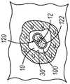
图1A、图1B和图1C示出了根据本公开的各方面的活检部位标记物的放置的示例性方面;1A, 1B and 1C illustrate exemplary aspects of placement of biopsy site markers according to aspects of the present disclosure;
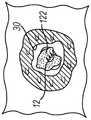
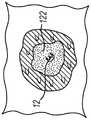
图2描绘了示例性标记物递送设备的透视图;Figure 2 depicts a perspective view of an exemplary marker delivery device;
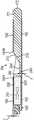
图3描绘了图2的标记物递送设备的侧视横截面视图;Figure 3 depicts a side cross-sectional view of the marker delivery device of Figure 2;
图4描绘了标记物从图1的标记物递送设备的远侧部分部署并穿过活检针中的横向孔以标记活检部位的横截面视图;4 depicts a cross-sectional view of a marker deployed from the distal portion of the marker delivery device of FIG. 1 and passed through a transverse hole in a biopsy needle to mark a biopsy site;
图5A描绘了用于与图2的标记物递送设备一起使用的示例性可替代标记物的俯视平面视图,该标记物的载体处于脱水状态;FIG. 5A depicts a top plan view of an exemplary replaceable marker for use with the marker delivery device of FIG. 2 with its carrier in a dehydrated state;
图5B描绘了图5A的标记物的另一个俯视平面视图,该标记物的载体处于部分脱水状态;Figure 5B depicts another top plan view of the marker of Figure 5A with its carrier in a partially dehydrated state;
图6A描绘了用于与图2的标记物递送设备一起使用的另一个示例性可替代标记物的俯视平面视图,该标记物的标记物元件处于平直构造;6A depicts a top plan view of another exemplary alternative marker for use with the marker delivery device of FIG. 2 , the marker element of the marker being in a flat configuration;
图6B描绘了图6A的标记物的另一个俯视平面视图,该标记物的标记物元件处于弯曲构造;6B depicts another top plan view of the marker of FIG. 6A with the marker elements of the marker in a curved configuration;
图7A描绘了用于与图2的标记物递送设备一起使用的又一个示例性替代标记物的俯视平面视图;7A depicts a top plan view of yet another exemplary surrogate marker for use with the marker delivery device of FIG. 2;
图7B描绘了图7A的标记物的局部透视图;Figure 7B depicts a partial perspective view of the marker of Figure 7A;
图8描绘了用于与图2的标记物递送设备一起使用的再一个示例性替代标记物的俯视平面视图;8 depicts a top plan view of yet another exemplary surrogate marker for use with the marker delivery device of FIG. 2;
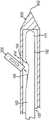
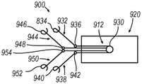
图9描绘了图8的标记物的前视正视图;Figure 9 depicts a front elevational view of the marker of Figure 8;
图10描绘了用于与图2的标记物递送设备一起使用的又一个示例性替代标记物的俯视平面视图;Figure 10 depicts a top plan view of yet another exemplary surrogate marker for use with the marker delivery device of Figure 2;
图11描绘了用于与图2的标记物递送设备一起使用的又一个示例性替代标记物的俯视平面视图;11 depicts a top plan view of yet another exemplary surrogate marker for use with the marker delivery device of FIG. 2;
图12描绘了用于与图2的标记物递送设备一起使用的又一个示例性替代标记物的俯视平面视图;并且12 depicts a top plan view of yet another exemplary surrogate marker for use with the marker delivery device of FIG. 2; and
图13描绘了图12的标记物的前视正视图。FIG. 13 depicts a front elevation view of the marker of FIG. 12 .
附图不旨在以任何方式进行限制,并且设想到,本发明的各种实施方案可以多种其他方式进行,包括附图中不一定描绘的那些方式。并入说明书并构成说明书的一部分的附图示出了本发明的若干方面,并且连同描述一起用于解释本发明的原理;然而,应当理解,本发明不限于所示的精确布置。The drawings are not intended to be limiting in any way, and it is contemplated that various embodiments of the invention may be practiced in numerous other ways, including those not necessarily depicted in the drawings. The accompanying drawings, which are incorporated in and constitute a part of this specification, illustrate several aspects of the invention and together with the description serve to explain the principles of the invention; however, it is to be understood that the invention is not limited to the precise arrangements shown.
具体实施方式Detailed ways
以下对本发明的某些示例的描述不应用来限制本发明的范围。从以下描述中,本领域技术人员将变得清楚本发明的其他示例、特征、方面、实施方案和优点,这些描述以说明方式进行,是被设想用于进行本发明的最佳模式之一。如将认识到,本发明能够具有其他不同和明显方面,所有这些方面都不脱离本发明。因此,附图和描述本质上应当被视为说明性而非限制性的。The following description of certain examples of the invention should not be taken to limit the scope of the invention. Other examples, features, aspects, embodiments and advantages of the invention will become apparent to those skilled in the art from the following description, which is done by way of illustration, which is one of the best modes contemplated for carrying out the invention. As will be realized, the invention is capable of other different and obvious aspects, all without departing from the invention. Accordingly, the drawings and descriptions should be regarded as illustrative in nature and not restrictive.
能够在移除病灶或对其进行采样之前或之后立即临时或永久地标记病灶的位置或边缘可能是有益的。如果需要,在移除之前进行标记可有助于确保切除整个病变。可替代地,如果无意中将病变全部移除,则在该规程之后立即标记活检部位将使得能够重新确立其位置以供将来识别。It may be beneficial to be able to temporarily or permanently mark the location or edges of a lesion either immediately before or immediately after removing or sampling the lesion. Marking prior to removal can help ensure resection of the entire lesion, if desired. Alternatively, marking the biopsy site immediately after the procedure will allow its location to be re-established for future identification if the lesion is inadvertently removed in its entirety.
一旦标记物被安设在活检部位处,就可能期望标记物在超声下保持可见。还可能期望使标记物相对于患者的其他结构特征可易于识别。例如,可能期望标记物在超声可视化下是能够与微钙化区分的,以避免在后续声检查期间无意中将标记物表征为微钙化。通常,微钙化点用于识别可疑病变或肿物的领域中。因此,通常期望超声视图作为标记物是可区分的,并且不会无意中被识别为新的肿块。Once the marker is installed at the biopsy site, it may be desirable for the marker to remain visible under ultrasound. It may also be desirable to make the marker readily identifiable relative to other structural features of the patient. For example, it may be desirable for a marker to be distinguishable from microcalcifications under ultrasound visualization to avoid inadvertently characterizing the marker as a microcalcification during subsequent sonography. Typically, microcalcifications are used in the field to identify suspicious lesions or masses. Therefore, it is generally expected that the ultrasound view is distinguishable as a marker and not inadvertently identified as a new mass.
I.示例性标记物I. Exemplary markers
本文呈现的方面涉及用于制造用于经皮标记具有周围组织(30)的活检腔(10)的标记物的设备和规程,如图1A至图1C中所示。例如,如图1A所示,标记物(100)最初可放置在活检腔(10)中以便于重新定位活检部位。标记物(100)可包括载体(120)和标记物元件(12)。载体(120)通常包括生物可吸收标记物材料(122)。因此,载体(120)通常被构造为在标记物(100)被放置在活检腔(10)内之后吸收到患者体内。在一些示例中,载体(120)可包括多个微泡,以增强载体(120)在超声下的可视化。如下文将更详细地描述的,标记物材料(122)通常是生物可吸收的,使得标记物材料(122)通常可随着时间的推移而被吸收到患者的组织中。在本示例中,标记物材料(122)包括最初呈脱水状态的水凝胶。尽管本示例中使用水凝胶,但是应当理解,在其他示例中,标记物材料(122)可包括其他已知的生物可吸收材料。Aspects presented herein relate to apparatus and procedures for manufacturing a marker for percutaneously marking a biopsy lumen (10) with surrounding tissue (30), as shown in FIGS. 1A-1C . For example, as shown in FIG. 1A , marker ( 100 ) may initially be placed in biopsy lumen ( 10 ) to facilitate repositioning of the biopsy site. A marker (100) may include a carrier (120) and a marker element (12). The carrier (120) typically includes a bioabsorbable marker material (122). Accordingly, carrier (120) is generally configured to be absorbed into the patient's body after marker (100) is placed within biopsy lumen (10). In some examples, carrier (120) may include a plurality of microbubbles to enhance visualization of carrier (120) under ultrasound. As will be described in more detail below, marker material (122) is generally bioabsorbable such that marker material (122) can generally be absorbed into the patient's tissue over time. In this example, marker material (122) comprises a hydrogel initially in a dehydrated state. Although a hydrogel is used in this example, it should be understood that in other examples the marker material (122) may comprise other known bioabsorbable materials.
在本示例中,标记物(100)还包括大体上不可生物吸收的标记物元件(12)。标记物元件(12)可包括嵌入在载体(120)的生物可吸收标记物材料(122)内的不透射线的或有回声的标记物。例如,标记物元件(12)可包括金属、硬塑料或本领域普通技术人员鉴于本文的教导已知的其他不透射线或高回声材料。在其他示例中,标记物(100)可形成为没有标记物元件(12)。在另一些其他示例中,标记物(100)可形成为仅具有标记物元件(12),以使得载体(120)被省略并且标记物元件(12)呈“裸”形式。换句话说,在一些示例中,标记物(100)仅由载体(120)形成为裸夹具(bare clip)。In this example, marker (100) also includes a substantially non-bioabsorbable marker element (12). The marker element (12) may comprise a radiopaque or echogenic marker embedded within the bioabsorbable marker material (122) of the carrier (120). For example, marker element (12) may comprise metal, hard plastic, or other radiopaque or hyperechoic materials known to those of ordinary skill in the art in light of the teachings herein. In other examples, marker (100) may be formed without marker element (12). In still other examples, marker (100) may be formed with only marker element (12), such that carrier (120) is omitted and marker element (12) is in "naked" form. In other words, in some examples, marker (100) is formed as a bare clip from carrier (120) only.
标记物材料(122)通常一旦设置在患者体内的活检部位处就可膨胀。如图1B和图1C所示,初始脱水的标记物材料(122)可从其插入其中的周围组织(30)吸收流体。响应于该流体吸收,标记物材料(122)可胀起,由此准许载体(120)填充因在活检规程期间移除组织样本而在活检部位处形成的腔。在期望准许自然组织生长物随着时间的推移而完全地或部分地替代所植入的材料的应用中,生物可降解材料可能特别地合适。因此,确保了生物相容性,并且组织的自然机械参数基本上恢复到受损前状态的那些参数。Marker material (122) is generally expandable once placed at the biopsy site within a patient. As shown in Figures IB and 1C, the initially dehydrated marker material (122) can absorb fluid from the surrounding tissue (30) into which it is inserted. In response to this fluid absorption, marker material (122) may swell, thereby permitting carrier (120) to fill a cavity formed at the biopsy site due to removal of a tissue sample during a biopsy procedure. Biodegradable materials may be particularly suitable in applications where it is desired to permit natural tissue growth to completely or partially replace the implanted material over time. Thus, biocompatibility is ensured and the natural mechanical parameters of the tissue are substantially restored to those of the pre-damage state.
标记物(100)可经由体腔(30)中的开口通过外科手术插入体内,或者使用诸如导管、导引器或类似类型的插入设备的设备通过最小侵入性规程插入体内。可在移除组织标本之后立即使用用于移除组织标本本身的同一设备来递送标记物(100)。随后,医生可使用随访非侵入性检测技术(诸如乳房x射线摄影或超声)来经由标记物(100)在一段时间内识别、定位和监测活检腔部位。Marker (100) may be inserted into the body either surgically through an opening in body cavity (30), or through minimally invasive procedures using a device such as a catheter, introducer, or similar type of insertion device. The marker (100) can be delivered immediately after removal of the tissue sample using the same device used to remove the tissue sample itself. The physician may then use follow-up non-invasive detection techniques such as mammography or ultrasound to identify, locate and monitor the biopsy cavity site via marker (100) over time.
例如,本示例的标记物(100)足够大以便临床医生在x射线或超声观察下容易看到;也足够小以便能够经皮部署到活检腔中并且不会给患者造成任何不便。尽管结合乳腺组织的治疗和诊断来描述示例,但是本文呈现的方面可用于任何内部组织(例如,乳腺组织、肺组织、前列腺组织、淋巴腺组织等)中的标记物。For example, the marker (100) of the present example is large enough to be easily seen by a clinician under x-ray or ultrasound observation; and small enough to be deployed percutaneously into a biopsy cavity without any inconvenience to the patient. Although the examples are described in connection with the treatment and diagnosis of breast tissue, the aspects presented herein can be used for markers in any internal tissue (eg, breast tissue, lung tissue, prostate tissue, lymph gland tissue, etc.).
载体(120)的标记物材料(122)被其周围的组织的天然水分水合而导致聚合物膨胀,并且因此使迁移的风险最小化。生长的基于水凝胶的标记物材料(122)随着其生长而将标记物(100)置于活检腔的中心。随着水凝胶膨胀,来自周围组织的天然存在的水分,水合使得越来越多的声音能够透射传输,出现越来越多的低回声并容易在后续的超声研究中可视化。The marker material (122) of the carrier (120) is hydrated by the natural moisture of its surrounding tissue causing the polymer to swell and thus minimizing the risk of migration. The growing hydrogel-based marker material (122) places the marker (100) in the center of the biopsy lumen as it grows. As the hydrogel swells, hydration from the naturally occurring moisture of the surrounding tissue allows more and more sound to be transmitted translucently, making it increasingly hypoechoic and easily visualized in subsequent ultrasound studies.
载体(120)的水合水凝胶标记物材料(122)还可用于构建持久标记物(12)。水合标记物材料(122)的低回声性质使得水凝胶水合标记物材料(122)内的永久标记物(12)能够超声可见,因为永久标记物(12)被概述为具有水状非反射基底的低回声水合标记物内的镜面反射体。The hydrated hydrogel marker material (122) of the carrier (120) can also be used to construct a durable marker (12). The hypoechoic nature of the hydrated marker material (122) enables ultrasound visualization of the permanent marker (12) within the hydrogel hydrated marker material (122), as the permanent marker (12) is outlined with a watery non-reflective base A specular reflector within the hypoechoic hydration marker.
II.示例性标记物递送设备II. Exemplary Marker Delivery Devices
在一些示例中,可能期望使用某些标记物递送设备将上文描述的标记物(100)部署在体腔(30)内。例如,图2和图3示出了示例性标记物递送设备(150),该标记物递送设备包括细长外套管(162),该细长外套管具有标记物出口,诸如邻近套管(162)的远侧端部形成但向近侧与该远侧端部间隔开的侧开口(164)。In some examples, it may be desirable to deploy the marker (100) described above within the body lumen (30) using certain marker delivery devices. For example, FIGS. 2 and 3 illustrate an exemplary marker delivery device (150) that includes an elongated outer cannula (162) having a marker outlet, such as adjacent to the cannula (162). ) forms a side opening (164) proximally spaced from the distal end thereof.
可在套管(162)的近侧端部处提供抓握部(166)。可提供推杆(168),其中推杆(168)在套管(162)中同轴地延伸,使得推杆(168)被构造成在套管(162)内平移,以使一个或多个标记物移位穿过侧开口(164)(参见图3)。杆(168)在压缩时可具有足够的刚度以将标记物从套管(162)的内部管腔(165)通过开口(164)推出,但在弯曲时是相对柔性的。柱塞(170)联接在杆(168)的近侧端部处,以用于将杆(168)在套管(162)中向远侧推动以将标记物部署在套管(162)外。A grip (166) may be provided at the proximal end of cannula (162). A push rod (168) may be provided, wherein the push rod (168) extends coaxially within the sleeve (162), such that the push rod (168) is configured to translate within the sleeve (162) to cause one or more The marker is displaced through the side opening (164) (see Figure 3). Rod (168) may be sufficiently rigid when compressed to push markers out of interior lumen (165) of cannula (162) through opening (164), but relatively flexible when bent. Plunger (170) is coupled at the proximal end of rod (168) for pushing rod (168) distally within cannula (162) to deploy markers outside of cannula (162).
使用者可用两个手指抓握抓握部(166),并且可用同一只手的拇指来推动柱塞(170),使得使用者用单手来操作标记物递送设备(160)。可围绕杆(168)设置弹簧(未示出)或另一特征件,以使杆(168)相对于抓握部(166)和套管(162)向近侧偏置。The user can grasp the grip (166) with two fingers and push the plunger (170) with the thumb of the same hand, allowing the user to operate the marker delivery device (160) with one hand. A spring (not shown) or another feature may be provided around rod (168) to bias rod (168) proximally relative to grip (166) and sleeve (162).
图3示出了标记物递送设备(160)的远侧部分的剖视图。如可看出,类似于上文描述的标记物(100)的活检标记物(300)设置在套管(162)的内部管腔(165)内。在本示例中,标记物(300)包括生物可降解或以其他方式可再吸收的标记物材料(306),诸如胶原、水凝胶等的大体圆柱形形状的主体,以及设置在标记物材料(306)内或以其他方式由该标记物材料携带的金属的大体不透射线的永久标记物或标记物元件(310)(以假想图示出)。Figure 3 shows a cross-sectional view of the distal portion of marker delivery device (160). As can be seen, biopsy marker (300), similar to marker (100) described above, is disposed within interior lumen (165) of cannula (162). In this example, the marker (300) includes a biodegradable or otherwise resorbable marker material (306), a generally cylindrically shaped body such as collagen, hydrogel, etc., and A metallic substantially radiopaque permanent marker or marker element (310) (shown in phantom) within (306) or otherwise carried by the marker material.
套管(162)可由任何合适的金属材料或非金属材料来形成。在一些变型中,套管(162)由合适医用级塑料或聚合物形成的薄壁中空管来形成。一种合适的材料为热塑性弹性体,诸如聚醚嵌段酰胺(PEBA),诸如以商标名为PEBAX已知者。套管(162)可由PEBAX形成,并且可对可见光和X射线基本上透明。Sleeve (162) may be formed from any suitable metallic or non-metallic material. In some variations, cannula (162) is formed from a thin-walled hollow tube formed from a suitable medical grade plastic or polymer. One suitable material is a thermoplastic elastomer, such as polyether block amide (PEBA), such as is known under the trade name PEBAX. Sleeve (162) can be formed from PEBAX and can be substantially transparent to visible light and X-rays.
可通过将套管(162)的壁的一部分切除来形成侧开口(164)。侧开口(164)与套管(162)的内部管腔(165)连通。侧开口(164)可从近侧开口端部(164A)轴向地(在平行于管腔(165)的轴线的方向上)延伸到远侧开口端部(164B),如图3所示。Side opening (164) may be formed by cutting away a portion of the wall of sleeve (162). Side opening (164) communicates with interior lumen (165) of cannula (162). Side opening (164) may extend axially (in a direction parallel to the axis of lumen (165)) from proximal opening end (164A) to distal opening end (164B), as shown in FIG.
在本示例中,远侧尖端(172)从套管(162)的远侧端部延伸并且是圆形化的,如图3所示。参考图3,套管(162)的远侧端部由整体端件(171)闭合,其中端件(171)的一部分延伸到套管(162)的内部管腔(165)中。端件(171)可以是模制部件或浇铸部件。端件(171)包括尖端(172)、具有斜坡表面(212)的斜坡(210),以及标记物接合元件(240)。斜坡表面(212)有助于引导标记物(300)从内部管腔(165)穿过侧开口(164)。标记物接合元件(240)有助于将标记物(300)保持在内部管腔(165)中,直到使用者打算部署标记物(300)为止。In this example, distal tip (172) extends from the distal end of cannula (162) and is rounded, as shown in FIG. Referring to FIG. 3, the distal end of cannula (162) is closed by integral end piece (171), wherein a portion of end piece (171) extends into inner lumen (165) of cannula (162). The end piece (171) may be a molded or cast part. End piece (171) includes tip (172), ramp (210) having ramped surface (212), and marker engaging element (240). Ramp surface (212) helps guide marker (300) from inner lumen (165) through side opening (164). Marker engagement element (240) helps to retain marker (300) within inner lumen (165) until a user intends to deploy marker (300).
标记物接合元件(240)设置在内部管腔(165)内,并且标记物接合元件(240)的至少一部分设置在侧开口(164)的近侧端部(164A)的远侧。标记物接合元件(240)在开口(164)下方沿套管(162)的底板的一部分延伸,使得标记物接合元件(240)被安设成增强套管(162)的形成有开口(164)的部分。例如,通过将标记物接合元件(240)安设在开口(164)下方,如图3所示,元件(240)有助于在切割套管(162)的壁以形成开口(164)的区域中对套管(162)进行强化。如图3所示,标记物接合元件(240)从斜坡表面(212)的最近侧部分延伸,并且并不向侧开口(164)的近侧延伸,但是在其他实施方案中,元件(240)的一部分可向开口(164)的近侧延伸。A marker engaging element (240) is disposed within inner lumen (165), and at least a portion of marker engaging element (240) is disposed distal to proximal end (164A) of side opening (164). The marker engaging element (240) extends below the opening (164) along a portion of the floor of the cannula (162), such that the marker engaging element (240) is positioned to reinforce the cannula (162) formed with the opening (164). part. For example, by placing the marker engaging element (240) below the opening (164), as shown in Figure 3, the element (240) helps to cut the wall of the cannula (162) in the region of the opening (164). Strengthen the casing (162). As shown in Figure 3, marker engagement element (240) extends from the most proximal portion of ramp surface (212) and does not extend proximally of side opening (164), but in other embodiments, element (240) A portion of can extend proximally of opening (164).
如图3中所示,标记物接合元件(240)呈台阶形式,其沿着元件(240)的轴向长度具有大体均匀的厚度(T),只是元件(240)具有渐细的近侧端部(242)。渐缩的近侧端部(242)与管腔(165)的纵向轴线形成约45度的夹角(图3中与水平线的夹角),而斜坡表面(212)与纵向轴线形成约30度的夹角。当然,可使用任何数值的其他合适的角度。As shown in Figure 3, marker engaging element (240) is in the form of a step having a generally uniform thickness (T) along the axial length of element (240), except that element (240) has a tapered proximal end Ministry (242). The tapered proximal end (242) forms an angle of about 45 degrees with the longitudinal axis of the lumen (165) (the angle with the horizontal in FIG. 3 ), while the ramp surface (212) forms an angle of about 30 degrees with the longitudinal axis. angle. Of course, other suitable angles of any value may be used.
如图3所示,标记物接合元件(240)的面向上的表面(244)(面向开口(164)的表面)向远侧延伸以接触斜坡表面(212),使得在表面(244)和斜坡表面(212)之间没有空间或间隙。这种布置有利于减小标记物(300)在移动经过标记物接合元件(240)时可能卡在标记物接合元件(240)与斜坡(212)之间的可能性。在一些变型中,标记物接合元件(240)、斜坡(210)和/或尖端(172)由比套管(162)的壁相对更不透射线的材料形成或包含该材料。例如,在元件(240)、斜坡(210)和尖端(172)形成为一体化端件(171)的情况下,端件(171)可包括不透射线添加剂,诸如硫酸钡。例如,端件(171)可以是由PEBAX模制的部件,其中向熔融的PEBAX模具组合物添加约20重量%的硫酸钡。相对更不透射线的标记物接合元件(240)、斜坡(210)和尖端(22)可用于使用射线照相成像来区分那些部件的位置。另外,在斜坡(210)和/或接合元件(240)的台阶与开口(164)相关联地安设的情况下,添加不透射线料可有助于在部署标记物(300)之前、期间或之后识别开口(164)的位置和标记物(300)相对于开口(164)的位置。As shown in FIG. 3 , upwardly facing surface ( 244 ) of marker engaging element ( 240 ) (the surface facing opening ( 164 )) extends distally to contact ramp surface ( 212 ), such that there is a gap between surface ( 244 ) and ramp. There are no spaces or gaps between surfaces (212). This arrangement advantageously reduces the likelihood that marker (300) may become lodged between marker engaging element (240) and ramp (212) as it moves past marker engaging element (240). In some variations, marker engaging element ( 240 ), ramp ( 210 ), and/or tip ( 172 ) are formed from or comprise a material that is relatively less radiopaque than the walls of cannula ( 162 ). For example, where element (240), ramp (210) and tip (172) are formed as an integral end piece (171), end piece (171) may include a radiopaque additive, such as barium sulfate. For example, the end piece (171) may be a part molded from PEBAX, where about 20% by weight barium sulfate is added to the molten PEBAX mold composition. Relatively more radiopaque marker engagement elements (240), ramps (210) and tips (22) can be used to distinguish the location of those components using radiographic imaging. In addition, where ramp (210) and/or step of engagement element (240) are installed in association with opening (164), adding radiopaque material may facilitate Or thereafter identify the location of the opening (164) and the location of the marker (300) relative to the opening (164).
参考图4,标记物递送设备(160)被用于部署标记物(300)以标记患者体内的活检位置。在图4中,套管式活检针(400)被示出为具有带有穿刺尖端(402)的闭合远侧端部以及横向组织接纳孔(414)。通过活检针(400)将标记物递送设备(160)引入到活检部位,该活检针可以是用于从活检部位采集组织样本的同一根针(400)。活检针(400)可以是与单次插入、多样本真空辅助活检设备一起使用的类型。本文提及并以引用方式并入本文的各种专利和专利申请中公开了若干此类活检设备,但是可使用其他活检设备。Referring to Figure 4, marker delivery device (160) is used to deploy marker (300) to mark a biopsy site within a patient. In FIG. 4, cannula biopsy needle (400) is shown having a closed distal end with piercing tip (402) and a transverse tissue receiving aperture (414). Marker delivery device (160) is introduced to the biopsy site via biopsy needle (400), which may be the same needle (400) used to collect the tissue sample from the biopsy site. Biopsy needle (400) may be of the type used with single-insertion, multiple-sample vacuum-assisted biopsy devices. Several such biopsy devices are disclosed in various patents and patent applications mentioned herein and incorporated herein by reference, although others may be used.
图4示出了设置在针(400)内的标记物递送设备(160)的远侧端部。可将针(400)安设在组织中,并且可通过横向孔(414)获得活检样本,由此邻近横向孔(414)提供活检腔。然后,在已经获得了组织样本并通过针(400)将该组织样本向近侧转移之后,并且在不从患者的组织移除针(400)的情况下,将标记物递送设备(160)插入到针(400)中的近侧开口中。在图4中,针(400)和标记物递送设备(160)被安设成使得套管(162)的开口(164)与针(400)的横向孔(414)基本上轴向且周向对准。然后,在标记物递送设备(160)和针(400)如此被安设在活检部位处的情况下,推进推杆(168)以将标记物(300)沿斜坡表面(212)向上、通过开口(164)并然后通过横向孔(414)部署到活检腔中。Figure 4 shows the distal end of marker delivery device (160) disposed within needle (400). Needle (400) may be positioned in tissue and a biopsy sample may be obtained through transverse hole (414), thereby providing a biopsy lumen adjacent to transverse hole (414). Then, after a tissue sample has been obtained and transferred proximally by needle (400), and without removing needle (400) from the patient's tissue, marker delivery device (160) is inserted into the into the proximal opening in needle (400). In FIG. 4, the needle (400) and marker delivery device (160) are positioned such that the opening (164) of the cannula (162) is substantially axial and circumferential to the transverse bore (414) of the needle (400). alignment. Then, with marker delivery device (160) and needle (400) so positioned at the biopsy site, push rod (168) is advanced to push marker (300) up ramp surface (212), through opening (164) and then deployed through the transverse hole (414) into the biopsy lumen.
III.针对有限迁移的示例性活检部位标记物III. Exemplary Biopsy Site Markers for Limited Migration
在一些示例中,可能期望在类似于标记物(100)的标记物内纳入某些特征件以降低标记物在被放置在组织内时迁移的风险。例如,由于组织在介于标记物放置与后续随访规程之间的间隔时间内移动,因此一些标记物在放置在活检部位处之后可能易于迁移。因此,此类标记物可能在后续随访规程期间就识别活检部位带来挑战。因此,可能期望将特征件并入到类似于标记物(100)的标记物中以随着时间的推移而维持标记物在组织内处于固定位置。尽管本文描述了并入有上文概述的特征件的若干示例,但是应当理解,在不脱离本文描述的基本原理的情况下,可使用各种可替代组合。In some examples, it may be desirable to incorporate certain features within a marker similar to marker (100) to reduce the risk of the marker migrating when placed within tissue. For example, some markers may be prone to migration after placement at the biopsy site due to tissue movement in the interval between marker placement and subsequent follow-up procedures. Thus, such markers may present challenges in identifying biopsy sites during subsequent follow-up protocols. Accordingly, it may be desirable to incorporate features into markers like marker ( 100 ) to maintain the marker in a fixed position within the tissue over time. While several examples are described herein that incorporate the features outlined above, it should be understood that various alternative combinations may be used without departing from the underlying principles described herein.
A.具有多模式锚定的示例性活检部位标记物A. Exemplary biopsy site markers with multimodal anchoring
图5A和图5B示出了示例性标记物(500),该标记物(500)通常被构造为在活检部位递送后锚定到组织从而限制该标记物(500)相对于在组织中的初始放置迁移。标记物(500)通常还被构造为对活检部位处的一种或多种情况作出响应以随着时间的推移增加锚定,从而进一步有助于限制标记物(500)的迁移。Figures 5A and 5B illustrate an exemplary marker (500) that is generally configured to anchor to tissue after delivery at a biopsy site thereby constraining the marker (500) relative to its initial position in the tissue. Place the migration. Marker (500) is also typically configured to increase anchoring over time in response to one or more conditions at the biopsy site, further helping to limit migration of marker (500).
与上述标记物(100)一样,本示例的标记物(500)包括载体(520)和标记物元件(512)。与上述载体(120)一样,本示例的载体(520)通常包括生物可吸收标记物材料(522)。因此,载体(520)通常被构造为在将标记物(500)放置在活检腔(诸如上述活检腔(10))内之后吸收到患者体内。本示例的载体(520)限定了大体圆柱形形状,但可使用多种其他形状。如上面类似地描述的,载体(520)的一些示例可包括多个微泡,以增强载体(520)在超声下的可视化。Like the marker (100) described above, the marker (500) of this example includes a carrier (520) and a marker element (512). As with the carrier (120) described above, the carrier (520) of the present example generally includes a bioabsorbable marker material (522). Accordingly, carrier (520) is generally configured to be absorbed into the patient's body after marker (500) is placed within a biopsy lumen, such as biopsy lumen (10) described above. The carrier (520) of this example defines a generally cylindrical shape, although a variety of other shapes may be used. As similarly described above, some examples of the carrier (520) may include a plurality of microbubbles to enhance visualization of the carrier (520) under ultrasound.
本示例的标记物材料(522)包含水凝胶或其他合适的材料。水凝胶材料通常被构造为随着时间的推移吸收到患者的组织中。因此,标记物材料(522)通常是非永久性的。另外地,水凝胶通常被构造为在放置在组织内时膨胀或溶胀。如下面将更详细地描述的,水凝胶可在被部署在活检部位处或部署在活检腔内之前被脱水和/或固化。一旦水凝胶接触组织,水凝胶就可从组织吸收水分并随着水凝胶中的水分增加而膨胀或溶胀。在一些示例中,还可在脱水和/或固化期间操纵水凝胶以根据各种膨胀曲线(例如,极限纵向膨胀、极限横向膨胀等)来控制水凝胶的膨胀。尽管在本文中将标记物材料(522)描述为水凝胶,但应当理解,在其他示例中,标记物材料(522)可包括其他合适的材料或包括具有或没有水凝胶的合适材料的各种组合。The marker material (522) of this example comprises a hydrogel or other suitable material. Hydrogel materials are typically constructed to absorb into a patient's tissue over time. Thus, marker material (522) is generally non-permanent. Additionally, hydrogels are typically configured to expand or swell when placed within tissue. As will be described in more detail below, the hydrogel may be dehydrated and/or cured prior to being deployed at the biopsy site or within the biopsy lumen. Once the hydrogel contacts the tissue, the hydrogel can absorb water from the tissue and expand or swell as the water in the hydrogel increases. In some examples, the hydrogel can also be manipulated during dehydration and/or curing to control the expansion of the hydrogel according to various swelling curves (eg, extreme longitudinal expansion, extreme transverse expansion, etc.). Although the marker material (522) is described herein as a hydrogel, it should be understood that in other examples, the marker material (522) may comprise other suitable materials or include suitable materials with or without hydrogels. Various combinations.
与上述标记物元件(12)一样,本示例的标记物元件(512)至少部分地设置在载体(520)的一部分内。然而,与标记物元件(12)不同,标记物元件(512)的一个或多个部分设置在载体(520)的外部。如下面将更详细地描述的,标记物元件(512)的这种构造通常被构造为促进标记物(500)在组织内的锚定。As with marker element (12) described above, marker element (512) of the present example is at least partially disposed within a portion of carrier (520). However, unlike marker element (12), one or more portions of marker element (512) are disposed on the exterior of carrier (520). As will be described in more detail below, this configuration of marker element (512) is generally configured to facilitate anchoring of marker (500) within tissue.
本示例的标记物元件(512)包括主锚(530)(可替代地称为“叉状件(harpoon)”)、一个或多个辅锚(534)(可替代地称为“外伸支腿(outrigger)”)以及将主锚(530)和该一个或多个辅锚(534)连接或接合的盘管(536)。如下面将更详细地描述的,锚(530、534)通常被构造为接合组织以将标记物(500)锚定在组织内。The marker element (512) of this example includes a primary anchor (530) (alternatively referred to as a "harpoon"), one or more secondary anchors (534) (alternatively referred to as an "outrigger") legs (outrigger)") and coiled tubing (536) connecting or joining the primary anchor (530) and the one or more secondary anchors (534). As will be described in more detail below, anchors (530, 534) are generally configured to engage tissue to anchor marker (500) within the tissue.
本示例的主锚(530)通常被构造为提供与组织的初始接合和锚定。为了促进此种接合,主锚(530)包括设置在主锚(530)的远侧端部上的倒钩(532)。类似于鱼钩或其他结构,倒钩(532)被构造为当在一个方向上(例如,向远侧)受力时穿透组织,但当在相反方向上(例如,向近侧)受力时抓住或粘住组织。因此,应当理解,倒钩(532)可包括尖锐的远侧端部和与尖锐的远侧端部成角度的向近侧定向的突出部。尽管本示例被示出为包括单个倒钩(532),但应当理解,在其他示例中,多个倒钩(532)和/或向近侧定向的突出部可沿着主锚(530)的长度并入到主锚(530)中。Primary anchor (530) of the present example is generally configured to provide initial engagement and anchoring with tissue. To facilitate such engagement, main anchor (530) includes barbs (532) disposed on the distal end of main anchor (530). Similar to a fishhook or other structure, barbs (532) are configured to penetrate tissue when forced in one direction (e.g., distally), but to penetrate tissue when forced in the opposite direction (e.g., proximally). grasp or stick to tissue. Accordingly, it should be appreciated that barb (532) may include a sharpened distal end and a proximally oriented protrusion angled from the sharpened distal end. Although this example is shown as including a single barb (532), it should be understood that in other examples, multiple barbs (532) and/or proximally directed projections may be along the length of main anchor (530). The length is incorporated into the main anchor (530).
主锚(530)从盘管(536)向远侧延伸。主锚(530)的至少一部分延伸到载体(520)之外,从而使得主锚(530)的一部分被构造为接合组织。如下面将更详细地描述的,主锚(530)的特定延伸长度通常与载体(520)的水凝胶的预定膨胀有关。例如,主锚(530)的延伸通常具有足够的长度,使得倒钩(532)即使在载体(520)在组织内完全膨胀之后仍保持与组织接合。Main anchor (530) extends distally from coiled tubing (536). At least a portion of primary anchor (530) extends beyond carrier (520), such that a portion of primary anchor (530) is configured to engage tissue. As will be described in more detail below, the particular extension length of primary anchor (530) is generally related to the predetermined expansion of the hydrogel of carrier (520). For example, the extension of main anchor (530) is generally of sufficient length such that barbs (532) remain engaged with the tissue even after carrier (520) is fully expanded within the tissue.
尽管本示例被示出为包括单个主锚(530),但在其他示例中,可使用多个主锚(530)。例如,在一些示例中,两个主锚(530)可相对于由载体(520)限定的纵向轴线以一定角度从盘管(536)向远侧延伸。在其他示例中,一个主锚(530)可向远侧延伸,如图所示,而另一个主锚(530)可从盘管(536)向近侧延伸。在又一些其他示例中,多个主锚(530)可从盘管(536)的远侧向近侧延伸、向远侧延伸或两者兼而有之。Although this example is shown as including a single primary anchor (530), in other examples multiple primary anchors (530) may be used. For example, in some examples, two main anchors (530) may extend distally from coiled tubing (536) at an angle relative to a longitudinal axis defined by carrier (520). In other examples, one main anchor (530) can extend distally, as shown, while the other main anchor (530) can extend proximally from coiled tubing (536). In still other examples, plurality of main anchors (530) may extend distally to proximally, distally, or both from the distal side of coiled tubing (536).
一个或多个辅锚(534)从盘管(536)横向地从载体(520)的内部延伸到载体(520)的外部。一个或多个辅锚(534)一起被构造为提供将标记物(500)另外锚定在组织内。如下面将更详细地描述的,一旦标记物(500)被放置在组织内,此种锚定就可随着时间的推移增加,因为每个辅锚(534)均被构造为响应于载体(520)的膨胀。One or more secondary anchors (534) extend laterally from the coiled tubing (536) from the interior of the carrier (520) to the exterior of the carrier (520). Together, one or more secondary anchors (534) are configured to provide additional anchoring of marker (500) within tissue. As will be described in more detail below, once the marker (500) is placed within the tissue, this anchoring can increase over time because each secondary anchor (534) is configured to respond to the carrier ( 520) expansion.
每个辅锚(534)包括细长的线棒形状的构型(construction)。每个辅锚(534)进一步从盘管(536)向外延伸。每个辅锚(534)的延伸被示出为横向延伸或远离由载体(520)限定的纵向轴线延伸。另外地,每个辅锚(534)被示出为相对于由载体(520)限定的纵向轴线成一定角度,使得每个辅锚(534)也向近侧(或远离主锚(530)的延伸)延伸。在这个取向中,每个辅锚(534)均被构造为允许标记物(500)在一个方向(例如,远侧)上移动,但防止标记物(500)在另一个方向(例如,近侧)上移动。Each secondary anchor (534) includes an elongated wire rod-shaped construction. Each secondary anchor (534) further extends outwardly from the coiled tubing (536). The extension of each secondary anchor (534) is shown extending laterally or away from the longitudinal axis defined by the carrier (520). Additionally, each secondary anchor (534) is shown at an angle relative to the longitudinal axis defined by carrier (520), such that each secondary anchor (534) is also positioned proximally (or away from) the primary anchor (530). Extend) extend. In this orientation, each secondary anchor (534) is configured to allow movement of marker (500) in one direction (e.g., distally), but prevent movement of marker (500) in another direction (e.g., proximally). ) to move up.
每个辅锚(534)均被构造为具有大体类似弹簧的特征。例如,每个辅锚(534)可以是足够柔性的,从而能够弯曲并由此允许在一个方向(例如,远侧)上的移动,但又是足够刚性的,从而能够防止标记物(500)在相反方向(例如,近侧)上的移动。此类特性可通过每个辅锚(534)的特定材料、每个辅锚(534)的尺寸(例如,直径)或两者的组合来促进。Each secondary anchor (534) is configured with generally spring-like characteristics. For example, each secondary anchor (534) may be flexible enough to bend and thereby allow movement in one direction (eg, distally), yet rigid enough to prevent markers (500) from Movement in the opposite direction (eg, proximal). Such properties may be facilitated by the particular material of each secondary anchor (534), the size (eg, diameter) of each secondary anchor (534), or a combination of both.
本示例的标记物元件(512)被示出为包括两个辅锚(534),其中一个辅锚(534)从载体(520)的每一侧突出。在其他示例中,标记物元件(512)可包括任何合适数量的辅锚(534)。例如,在一些示例中,标记物元件(512)可包括从载体(520)的每一侧延伸的多个辅锚(534)。在其他示例中,辅锚(534)的数目可以是不对称的,其中一个辅锚(534)从载体(520)的一侧延伸并且多个辅锚(534)从载体(520)的另一侧延伸。The marker element (512) of this example is shown to include two secondary anchors (534), with one secondary anchor (534) protruding from each side of the carrier (520). In other examples, marker element (512) may include any suitable number of secondary anchors (534). For instance, in some examples, marker element (512) may include a plurality of secondary anchors (534) extending from each side of carrier (520). In other examples, the number of secondary anchors (534) may be asymmetrical, with one secondary anchor (534) extending from one side of the carrier (520) and multiple secondary anchors (534) extending from the other side of the carrier (520). side extension.
如上所述,盘管(536)将主锚(530)和每个辅锚(536)接合或连接。盘管(536)包括一个或多个线材环圈以便相对于x射线源和检测器以各种角度增强标记物元件(512)在x射线可视化下的可视化。另外地,盘管(536)的一个或多个环圈可被构造为将标记物元件(512)锚定在载体(520)内,从而为主锚(530)和每个辅锚(536)提供机械基础(mechanicalground)。As described above, coiled tubing (536) engages or connects primary anchor (530) and each secondary anchor (536). Coil (536) includes one or more loops of wire to enhance visualization of marker element (512) under x-ray visualization at various angles relative to the x-ray source and detector. Additionally, one or more loops of coiled tubing (536) may be configured to anchor marker element (512) within carrier (520) such that primary anchor (530) and each secondary anchor (536) Provides a mechanical ground.
本示例的盘管(536)与主锚(530)和每个辅锚(536)是一体化的。然而,在其他示例中,盘管(536)可以是单独的部件,其中主锚(530)和/或每个辅锚(536)被连接、固定和/或紧固到盘管(536)。无论如何,在一些示例中,盘管(536)可另外被构造为向每个辅锚(536)提供至少一些弹性。在该一体化构型情况下,盘管(536)、主锚(530)和每个辅锚(536)包括单一的普通材料,诸如金属。仅以举例的方式,用于盘管(536)、主锚(530)和每个辅锚(536)的仅仅是示例性的合适材料可包括生物可相容的合金,诸如镍钛诺、不锈钢、钛等。Coil (536) of this example is integral with primary anchor (530) and each secondary anchor (536). However, in other examples, coiled tubing (536) may be a separate component, with primary anchor (530) and/or each secondary anchor (536) connected, secured, and/or secured to coiled tubing (536). Regardless, in some examples, coiled tubing (536) may additionally be configured to provide at least some resiliency to each secondary anchor (536). With this unitary configuration, coiled tubing (536), primary anchor (530), and each secondary anchor (536) comprise a single common material, such as metal. By way of example only, only exemplary suitable materials for coil (536), primary anchor (530), and each secondary anchor (536) may include biocompatible alloys such as nitinol, stainless steel , titanium, etc.
图5A和图5B共同示出了标记物(500)的示例性使用。例如,图5A示出了处于初始脱水构造的标记物(500)。此种构造可对应于被装载到类似于上述标记物递送设备(150)的标记物递送设备中的标记物(500)。此种构造还可对应于紧接在部署在活检部位处之后标记物(500)的状况。Figures 5A and 5B together illustrate an exemplary use of marker (500). For example, Figure 5A shows a marker (500) in an initial dehydrated configuration. Such a configuration may correspond to a marker (500) loaded into a marker delivery device similar to marker delivery device (150) described above. Such a configuration may also correspond to the condition of marker (500) immediately after deployment at the biopsy site.
在初始脱水构造中,可使用标记物递送设备(150)或任何其他合适的装置将标记物(500)插入到活检部位中。在插入期间,由主锚(530)的倒钩(532)限定的尖锐尖端可穿透到组织中。这种穿透设定了倒钩(532)的相邻突起从而设定标记物(500)的轴向位置并且限制标记物(500)向后穿过用于部署标记物(500)的腔的近侧移动。辅锚(534)可同样通过响应于标记物(500)穿过组织的远侧移动而弯曲或以其他方式移动来促进插入到组织中。由于每个辅锚(534)的近侧取向,辅锚(534)还可限制标记物(500)向后穿过用于部署标记物(500)的腔的近侧移动。In the initial dehydrated configuration, marker (500) may be inserted into the biopsy site using marker delivery device (150) or any other suitable means. During insertion, the sharp tip defined by barb (532) of primary anchor (530) can penetrate into tissue. This penetration sets the adjacent projections of the barbs (532) thereby setting the axial position of the marker (500) and limiting the backward movement of the marker (500) through the lumen used to deploy the marker (500). Move proximally. Secondary anchor (534) may likewise facilitate insertion into tissue by bending or otherwise moving in response to distal movement of marker (500) through the tissue. Due to the proximal orientation of each secondary anchor (534), secondary anchors (534) may also limit the proximal movement of marker (500) rearwardly through the lumen used to deploy marker (500).
在标记物(500)被部署在组织中之后,标记物材料(522)可从周围组织吸收流体。这种吸收将导致载体(520)随着时间的推移而膨胀或溶胀,如图5B所示。这种膨胀或溶胀可引起每个辅锚(534)的对应移动,从而增加每个辅锚(534)相对于载体(520)的纵向轴线的角度。随着每个辅锚(534)的角度增加,标记物(500)在组织内的固定可经由每个辅锚(534)来增加。尽管每个辅锚(534)的至少一些移动可通过标记物材料(522)的膨胀来促进,但应当理解,在一些示例中,至少一些移动可由辅锚(534)本身的弹性或由盘管(536)提供的弹性来促成。After marker (500) is deployed in tissue, marker material (522) can absorb fluid from surrounding tissue. This absorption will cause the carrier (520) to swell or swell over time, as shown in Figure 5B. This expansion or swelling can cause a corresponding movement of each secondary anchor (534), thereby increasing the angle of each secondary anchor (534) relative to the longitudinal axis of the carrier (520). As the angle of each secondary anchor (534) increases, fixation of marker (500) within tissue can be increased via each secondary anchor (534). While at least some movement of each secondary anchor (534) may be facilitated by expansion of marker material (522), it should be understood that in some examples at least some movement may be caused by the elasticity of secondary anchors (534) themselves or by coiled tubing. (536) provides flexibility to facilitate.
B.具有弯曲构件的示例性活检部位标记物B. Exemplary biopsy site markers with curved members
图6A和图6B示出了示例性标记物(600),该标记物(600)通常被构造为在一个或多个点处弯曲以在活检部位递送后锚定到组织并且限制该标记物(600)相对于在组织中的初始放置的迁移。与上述标记物(100)一样,本示例的标记物(600)包括载体(620)和标记物元件(612)。与上述载体(120)一样,本示例的载体(620)通常包括生物可吸收标记物材料(622)。因此,载体(620)通常被构造为在将标记物(600)放置在活检腔(诸如上述活检腔(10))内之后吸收到患者体内。本示例的载体(620)限定了大体圆柱形形状,但可使用多种其他形状。如上面类似地描述的,载体(620)的一些示例可包括多个微泡,以增强载体(620)在超声下的可视化。6A and 6B illustrate an exemplary marker (600) that is generally configured to bend at one or more points to anchor to tissue and confine the marker ( 600) Migration relative to initial placement in tissue. Like the marker (100) described above, the marker (600) of this example includes a carrier (620) and a marker element (612). As with the carrier (120) described above, the carrier (620) of the present example generally includes a bioabsorbable marker material (622). Accordingly, carrier (620) is generally configured to be absorbed into the patient's body after marker (600) is placed within a biopsy lumen, such as biopsy lumen (10) described above. The carrier (620) of this example defines a generally cylindrical shape, although a variety of other shapes may be used. As similarly described above, some examples of the carrier (620) may include a plurality of microbubbles to enhance visualization of the carrier (620) under ultrasound.
本示例的标记物材料(622)包含水凝胶或其他合适的材料。水凝胶材料通常被构造为随着时间的推移吸收到患者的组织中。因此,标记物材料(622)通常是非永久性的。另外地,水凝胶通常被构造为在放置在组织内时膨胀或溶胀。如下面将更详细地描述的,水凝胶可在被部署在活检部位处或部署在活检腔内之前被脱水和/或固化。一旦水凝胶接触组织,水凝胶就可从组织吸收水分并随着水凝胶中的水分增加而膨胀或溶胀。在一些示例中,还可在脱水和/或固化期间操纵水凝胶以根据各种膨胀曲线(例如,极限纵向膨胀、极限横向膨胀等)来控制水凝胶的膨胀。尽管在本文中将标记物材料(622)描述为水凝胶,但应当理解,在其他示例中,标记物材料(622)可包括其他合适的材料或包括具有或没有水凝胶的合适材料的各种组合。The marker material (622) of this example comprises a hydrogel or other suitable material. Hydrogel materials are typically constructed to absorb into a patient's tissue over time. Thus, marker material (622) is generally non-permanent. Additionally, hydrogels are typically configured to expand or swell when placed within tissue. As will be described in more detail below, the hydrogel may be dehydrated and/or cured prior to being deployed at the biopsy site or within the biopsy lumen. Once the hydrogel contacts the tissue, the hydrogel can absorb water from the tissue and expand or swell as the water in the hydrogel increases. In some examples, the hydrogel can also be manipulated during dehydration and/or curing to control the expansion of the hydrogel according to various swelling curves (eg, extreme longitudinal expansion, extreme transverse expansion, etc.). Although the marker material (622) is described herein as a hydrogel, it should be understood that in other examples, the marker material (622) may comprise other suitable materials or include suitable materials with or without hydrogels. Various combinations.
与上述载体(120)不同,载体(620)被分成两个部分:主元件(624)和辅元件(626)。如下面将更详细地描述的,辅元件(626)通常被构造为相对于主元件(624)移动以经由主元件(624)和辅元件(626)的组合来增强在组织中的锚定。在本示例中,主元件(624)和辅元件(626)两者被示出为具有类似的圆柱形形状。然而,应当理解,在其他示例中,主元件(624)和辅元件(626)可具有不类似的形状。Unlike the carrier (120) described above, the carrier (620) is divided into two parts: a primary element (624) and a secondary element (626). As will be described in more detail below, secondary element (626) is generally configured to move relative to primary element (624) to enhance anchoring in tissue via the combination of primary element (624) and secondary element (626). In this example, both primary element (624) and secondary element (626) are shown as having similar cylindrical shapes. It should be understood, however, that in other examples, primary element (624) and secondary element (626) may have dissimilar shapes.
与上述标记物元件(12)一样,本示例的标记物元件(612)至少部分地设置在载体(620)的一部分内。然而,与标记物元件(12)不同,标记物元件(612)的一个或多个部分设置在载体(620)的外部。例如,标记物元件(612)从主元件(624)延伸到辅元件(626),从而暴露标记物元件(612)的在主元件(624)与辅元件(626)之间的部分。如下面将更详细地描述的,标记物元件(612)的这种构造通常被构造为经由辅元件(626)相对于主元件(624)的移动来促进标记物(600)在组织内的锚定。As with marker element (12) described above, marker element (612) of the present example is disposed at least partially within a portion of carrier (620). However, unlike marker element (12), one or more portions of marker element (612) are disposed on the exterior of carrier (620). For example, marker element (612) extends from primary element (624) to secondary element (626), exposing a portion of marker element (612) between primary element (624) and secondary element (626). As will be described in more detail below, this configuration of marker element (612) is generally configured to facilitate anchoring of marker (600) within tissue via movement of secondary element (626) relative to primary element (624). Certainly.
标记物元件(612)包括弹簧(630)(可替代地称为“弹性构件”、“驱动构件”和/或“驱动器”)、主盘管(632)和辅盘管(634)。弹簧(630)设置在主盘管(632)与辅盘管(634)之间。尽管弹簧(630)在本示例中被示出为居于主盘管(632)与辅盘管(634)之间的中心,但应当理解,在一些示例中,弹簧(630)可相对于主盘管(632)和辅盘管(634)偏离中心地设置。Marker element (612) includes a spring (630) (alternatively referred to as a "resilient member", "drive member" and/or "driver"), a primary coil (632) and a secondary coil (634). The spring (630) is disposed between the primary coil (632) and the secondary coil (634). Although spring (630) is shown in this example as being centered between primary coil (632) and secondary coil (634), it should be understood that in some examples, spring (630) may be centered relative to primary coil (632) and secondary coil (634). Tube (632) and secondary coil (634) are located off-center.
不管弹簧(630)的具体位置如何,弹簧(630)都安设在载体(620)的主元件(624)和辅元件(626)两者的外部。这种构造通常是允许辅元件(626)相对于主元件(624)围绕由弹簧(630)限定的轴线的移动所期望的。因此,弹簧(630)通常被构造为驱动辅元件(626)和/或主元件(624)的移动。Regardless of the specific location of the spring (630), the spring (630) is mounted on the exterior of both the primary (624) and secondary (626) elements of the carrier (620). Such a configuration is generally desirable to allow movement of the secondary element (626) relative to the primary element (624) about the axis defined by the spring (630). Accordingly, spring (630) is generally configured to drive movement of secondary element (626) and/or primary element (624).
弹簧(630)可采取适合于驱动辅元件(626)相对于主元件(624)的移动的多种形式。在本示例中,弹簧(630)被示出为盘管弹簧或扭力弹簧。此种构造也可能是通过包括一个或多个重叠盘管来增强标记物元件(612)在x射线下的可见性所期望的。然而,可使用其他合适的构造。例如,在一些示例中,弹簧(630)可包括形状记忆材料,诸如镍钛诺。弹簧(630)然后可响应于来自周围组织的温度升高而从第一相对平直形状转变为第二弯曲形状。Spring (630) may take various forms suitable for driving movement of secondary element (626) relative to primary element (624). In this example, spring (630) is shown as a coil or torsion spring. Such a configuration may also be desirable to enhance the visibility of the marker element (612) under x-rays by including one or more overlapping coils. However, other suitable configurations may be used. For example, in some examples, spring (630) may comprise a shape memory material, such as Nitinol. The spring (630) may then transition from the first relatively flat shape to the second curved shape in response to an increase in temperature from the surrounding tissue.
主盘管(632)和辅盘管(634)设置在标记物元件(612)的相对的端部上。主盘管(632)设置在载体(620)的主元件(624)内。同时,辅盘管(634)设置在载体(620)的辅元件(626)内。这两个盘管(632、634)限定了在x射线和/或超声下可能可见的独特几何图案。例如,在一些示例中,盘管(632、634)可包括一个或多个线材环圈以便相对于x射线源和检测器以各种角度增强标记物元件(612)在x射线可视化下的可视化。另外地,每个盘管(632、634)的一个或多个环圈可被构造为将标记物元件(612)锚定在载体(620)的主元件(624)/辅元件(626)内,以由此为标记物元件(612)提供机械基础。在其他示例中,盘管(632、634)可以是在一个或多个点处弯曲以在x射线和/或超声下提供增强的可视化的带材或片材构造。在每个盘管(632、634)的任何上述构造中,此类盘管(632、634)可包括一个或多个开口和/或孔穴以进一步增强可视化。此外,每个盘管(632、634)不一定具有同一的构造。实际上,在一些示例中,可能期望在每个盘管(632、634)的构造之间具有至少一些变化,以更容易地识别标记物(600)的特定端部。Primary coil (632) and secondary coil (634) are disposed on opposite ends of marker element (612). The main coil (632) is disposed within the main element (624) of the carrier (620). Meanwhile, the secondary coil (634) is disposed within the secondary element (626) of the carrier (620). The two coils (632, 634) define a unique geometric pattern that may be visible under x-ray and/or ultrasound. For example, in some examples, coils (632, 634) may include one or more loops of wire to enhance visualization of marker elements (612) under x-ray visualization at various angles relative to the x-ray source and detectors . Additionally, one or more loops of each coil (632, 634) may be configured to anchor the marker element (612) within the primary (624)/secondary (626) element of the carrier (620) , to thereby provide a mechanical basis for the marker element (612). In other examples, the coiled tubing (632, 634) may be a tape or sheet construction that is bent at one or more points to provide enhanced visualization under x-ray and/or ultrasound. In any of the aforementioned configurations for each coil (632, 634), such coils (632, 634) may include one or more openings and/or holes to further enhance visualization. Furthermore, each coil (632, 634) does not have to be of identical construction. Indeed, in some examples, it may be desirable to have at least some variation between the configurations of each coil (632, 634) to more easily identify the particular end of marker (600).
本示例的每个盘管(632、634)与标记物元件(612)的其余部分是一体化的。此种构造可能是通过例如仅弯曲单根线材来促进制造的容易性所期望的。然而,在其他示例中,每个盘管(632、634)可以是单独的部件,其中标记物元件(612)的其他部分被连接、固定和/或紧固到每个盘管(632、634)。在该一体化构型的情况下,标记物元件(612)可包括单一的普通材料,诸如金属。仅以举例的方式,用于每个盘管(632、634)和标记物元件(612)的其他部件的仅仅是示例性的合适材料可包括生物可相容的合金,诸如镍钛诺、不锈钢、钛等。Each coil (632, 634) of this example is integral with the rest of the marker element (612). Such a configuration may be desirable to facilitate ease of manufacture by, for example, only bending a single wire. However, in other examples, each coil (632, 634) may be a separate component, with other portions of the marker element (612) connected, fixed and/or secured to each coil (632, 634) ). With this unitary configuration, marker element (612) may comprise a single common material, such as metal. By way of example only, only exemplary suitable materials for each coil (632, 634) and other components of the marker element (612) may include biocompatible alloys such as nitinol, stainless steel , titanium, etc.
图6A和图6B共同示出了标记物(600)的示例性使用。例如,图6A示出了处于初始平直构造的标记物(600)。这样的构造可对应于将标记物(600)装载到类似于上述标记物递送设备(150)的标记物递送设备中。虽然标记物(600)处于平直构造,但标记物(600)通常被构造为使用标记物递送设备部署在活检部位处。Figures 6A and 6B together illustrate an exemplary use of a marker (600). For example, Figure 6A shows marker (600) in an initial flat configuration. Such a configuration may correspond to loading markers (600) into a marker delivery device similar to marker delivery device (150) described above. While marker ( 600 ) is in a flat configuration, marker ( 600 ) is generally configured to be deployed at a biopsy site using a marker delivery device.
一旦标记物(600)被部署在活检部位处,标记物(600)就被构造为自动地转变为如图6B所示的弯曲构造。如可看出,弹簧(630)被构造为驱动辅元件(626)相对于主元件(624)围绕由弹簧(630)限定的轴线的移动。这种转变导致标记物(600)具有更不规则的形状,并且因此更可能锚定在活检部位处的组织内。在本示例中,示出了大约90°的旋转。然而,应当理解,在其他示例中,可使用各种其他旋转。仅以举例的方式,一个合适的旋转角度范围可包括大约70°至大约100°。Once marker ( 600 ) is deployed at the biopsy site, marker ( 600 ) is configured to automatically transition into a curved configuration as shown in FIG. 6B . As can be seen, spring (630) is configured to drive movement of secondary element (626) relative to primary element (624) about an axis defined by spring (630). This transition results in marker (600) having a more irregular shape, and thus more likely to be anchored within the tissue at the biopsy site. In this example, a rotation of approximately 90° is shown. However, it should be understood that in other examples, various other rotations may be used. By way of example only, a suitable range of rotational angles may include about 70° to about 100°.
如上所指出的,弹簧(630)可被构造为以多种方式驱动辅元件(626)的移动。在本示例中,此种移动是通过弹簧(630)被弹性地偏置从而使辅元件(626)从图6A所示的位置旋转到图6B所示的位置来实现的。在其他示例中,弹簧(630)可包括形状记忆合金。此种合金可能对周围组织的温度敏感,并且因此随着时间的推移,可随着弹簧(630)从环境温度升温到组织温度而缓慢地驱动辅元件(626)的移动。此种构造可能是促进与载体(620)的膨胀和/或溶胀至少部分地同时发生的辅元件(626)的移动所期望的。As noted above, spring (630) may be configured to drive movement of secondary element (626) in a variety of ways. In this example, such movement is achieved by spring (630) being resiliently biased to rotate secondary element (626) from the position shown in Figure 6A to the position shown in Figure 6B. In other examples, spring (630) may include a shape memory alloy. Such alloys may be sensitive to the temperature of the surrounding tissue, and thus may slowly drive movement of secondary element (626) over time as spring (630) warms from ambient temperature to tissue temperature. Such a configuration may be desirable to facilitate movement of secondary element (626) at least in part concurrently with expansion and/or swelling of carrier (620).
C.具有多个锚定元件的示例性活检部位标记物C. Exemplary biopsy site markers with multiple anchoring elements
图7A和图7B示出了示例性标记物(700),该标记物(700)通常被构造为使用跨多个平面定向的锚来锚定到组织以限制该标记物(700)相对于在组织中的初始放置的迁移。与上述标记物(100)一样,本示例的标记物(700)包括载体(720)和标记物元件(712)。与上述载体(120)一样,本示例的载体(720)通常包括生物可吸收标记物材料(722)。因此,载体(720)通常被构造为在将标记物(700)放置在活检腔(诸如上述活检腔(10))内之后吸收到患者体内。本示例的载体(720)限定了大体圆柱形形状,但可使用多种其他形状。如上面类似地描述的,载体(720)的一些示例可包括多个微泡,以增强载体(720)在超声下的可视化。7A and 7B illustrate an exemplary marker (700) generally configured to be anchored to tissue using anchors oriented across multiple planes to constrain the marker (700) relative to the Migration for initial placement in the organization. Like the marker (100) described above, the marker (700) of this example includes a carrier (720) and a marker element (712). As with the carrier (120) described above, the carrier (720) of the present example generally includes a bioabsorbable marker material (722). Accordingly, carrier (720) is generally configured to be absorbed into the patient's body after marker (700) is placed within a biopsy lumen, such as biopsy lumen (10) described above. The carrier (720) of this example defines a generally cylindrical shape, although a variety of other shapes may be used. As similarly described above, some examples of the carrier (720) may include a plurality of microbubbles to enhance visualization of the carrier (720) under ultrasound.
本示例的标记物材料(722)包含水凝胶或其他合适的材料。水凝胶材料通常被构造为随着时间的推移吸收到患者的组织中。因此,标记物材料(722)通常是非永久性的。另外地,水凝胶通常被构造为在放置在组织内时膨胀或溶胀。如下面将更详细地描述的,水凝胶可在被部署在活检部位处或部署在活检腔内之前被脱水和/或固化。一旦水凝胶接触组织,水凝胶就可从组织吸收水分并随着水凝胶中的水分增加而膨胀或溶胀。在一些示例中,还可在脱水和/或固化期间操纵水凝胶以根据各种膨胀曲线(例如,极限纵向膨胀、极限横向膨胀等)来控制水凝胶的膨胀。尽管在本文中将标记物材料(722)描述为水凝胶,但应当理解,在其他示例中,标记物材料(722)可包括其他合适的材料或包括具有或没有水凝胶的合适材料的各种组合。The marker material (722) of this example comprises a hydrogel or other suitable material. Hydrogel materials are typically constructed to absorb into a patient's tissue over time. Thus, marker material (722) is generally non-permanent. Additionally, hydrogels are typically configured to expand or swell when placed within tissue. As will be described in more detail below, the hydrogel may be dehydrated and/or cured prior to being deployed at the biopsy site or within the biopsy lumen. Once the hydrogel contacts the tissue, the hydrogel can absorb water from the tissue and expand or swell as the water in the hydrogel increases. In some examples, the hydrogel can also be manipulated during dehydration and/or curing to control the expansion of the hydrogel according to various swelling curves (eg, extreme longitudinal expansion, extreme transverse expansion, etc.). Although the marker material (722) is described herein as a hydrogel, it should be understood that in other examples, the marker material (722) can comprise other suitable materials or include suitable materials with or without hydrogels. Various combinations.
标记物元件(712)包括编织(braded)部分(730)和从编织部分(730)向远侧延伸的多个锚部分(732)(可替代地称为“外伸支腿”)。在本示例中,编织部分(730)完全设置在载体(720)内。在其他示例中,编织部分(730)的至少一部分可延伸到载体(720)之外。编织部分(730)由以重复图案编织在一起的多条线材限定。可使用各种合适的重复图案。通常,合适的重复图案可被构造为提供独特的图案以增强在x射线和/或超声可视化下的可视化。Marker element (712) includes a braded portion (730) and a plurality of anchor portions (732) (alternatively referred to as "outriggers") extending distally from braded portion (730). In this example, braided portion (730) is disposed entirely within carrier (720). In other examples, at least a portion of knitted portion (730) may extend beyond carrier (720). The braided portion (730) is defined by a plurality of wires braided together in a repeating pattern. Various suitable repeating patterns can be used. In general, a suitable repeating pattern can be configured to provide a unique pattern to enhance visualization under x-ray and/or ultrasound visualization.
锚部分(732)从编织部分(730)向远侧延伸。在本示例中,编织部分(730)包括三根线材,其中锚部分(732)由三根对应的未编织线材形成。可替代地,在其他示例中,可使用任何合适数量的线材,诸如两根、四根、五根或六根。每个锚部分(732)均被构造为以与每个其他锚部分(732)不同的角度从编织部分(730)的远侧端部向外突出以跨越多个不同的平面。在这种构造中,每个锚部分(732)均被构造为跨越多个平面而不是跨越单个平面来接合组织。Anchor portion (732) extends distally from braided portion (730). In this example, braided portion (730) includes three wires, with anchor portion (732) formed from three corresponding unbraided wires. Alternatively, any suitable number of wires may be used, such as two, four, five, or six, in other examples. Each anchor portion (732) is configured to project outwardly from the distal end of braided portion (730) at a different angle than every other anchor portion (732) to span a plurality of different planes. In this configuration, each anchor portion (732) is configured to engage tissue across multiple planes rather than across a single plane.
图7A和图7B示出了标记物(700)的示例性使用。例如,图7A示出了标记物(700)的构造,在一些示例中,该构造可对应于使用类似于上述标记物递送设备(150)的标记物递送设备部署在活检部位之后的构造。在这个位置处,锚部分(732)通常比处于完全锚定构造时更紧凑或更紧密地在一起。尽管锚部分(732)被示出为彼此之间仍有一些空间,但应当理解,在其他使用中,锚部分(732)可被放置得更靠近以便于部署。例如,在一些使用中,锚部分(732)可被压在一起以形成大体平直的远侧突出部。这种构造可能是促进使用类似于上述标记物递送设备(150)的标记物递送设备进行更平滑的部署所期望的。在其他使用中,可通过以与编织部分(730)的图案类似的图案编织锚部分(732)来进一步促进锚部分(732)的此种平直构造。在此种构造中,锚部分(732)的此种编织可相对松散以促进锚部分(732)随后相对于彼此铺展开。Figures 7A and 7B illustrate exemplary uses of markers (700). For example, FIG. 7A shows a configuration of marker (700), which in some examples may correspond to a configuration after deployment at a biopsy site using a marker delivery device similar to marker delivery device (150) described above. In this position, anchor portions (732) are generally more compact or closer together than in the fully anchored configuration. Although anchor portions (732) are shown with some space between them, it should be understood that in other uses, anchor portions (732) may be placed closer together to facilitate deployment. For example, in some uses, anchor portions (732) may be pressed together to form a generally straight distal protrusion. Such a configuration may be desirable to facilitate smoother deployment using a marker delivery device similar to the marker delivery device (150) described above. In other uses, this straight configuration of anchor portion (732) may be further facilitated by weaving anchor portion (732) in a pattern similar to that of braided portion (730). In such a configuration, such weaving of anchor portions (732) may be relatively loose to facilitate subsequent spreading of anchor portions (732) relative to each other.
在部署之后,锚部分(732)如图7B所示的那样在多个不同方向上铺展开。作为这种铺展开的结果,每个锚部分(732)均跨越多个不同的平面与活检部位处的组织相互啮合。因此,锚部分(732)共同被构造为跨越多个方向(例如,横向地和纵向地)将标记物(700)锚定在组织内。After deployment, the anchor portion (732) spreads out in a number of different directions as shown in Figure 7B. As a result of this spreading, each anchor portion (732) interengages tissue at the biopsy site across a plurality of different planes. Accordingly, anchor portions (732) are collectively configured to anchor marker (700) within tissue across multiple directions (eg, laterally and longitudinally).
D.具有多平面锚定元件的示例性活检部位标记物D. Exemplary biopsy site markers with multiplanar anchoring elements
图8和图9示出了示例性标记物(800),该标记物(800)通常被构造为使用沿着多个平面对准的锚来锚定到组织以限制标记物(800)相对于在组织中的初始放置的迁移。与上述标记物(100)一样,本示例的标记物(800)包括载体(820)和标记物元件(812)。与上述载体(120)一样,本示例的载体(820)通常包括生物可吸收标记物材料(822)。因此,载体(820)通常被构造为在将标记物(800)放置在活检腔(诸如上述活检腔(10))内之后吸收到患者体内。本示例的载体(820)限定了大体圆柱形形状,但可使用多种其他形状。如上面类似地描述的,载体(820)的一些示例可包括多个微泡,以增强载体(820)在超声下的可视化。8 and 9 illustrate exemplary markers (800) that are generally configured to be anchored to tissue using anchors aligned along multiple planes to constrain markers (800) relative to Migration for initial placement in the organization. Like the marker (100) described above, the marker (800) of this example includes a carrier (820) and a marker element (812). As with the carrier (120) described above, the carrier (820) of the present example generally includes a bioabsorbable marker material (822). Accordingly, carrier (820) is generally configured to be absorbed into the patient's body after marker (800) is placed within a biopsy lumen, such as biopsy lumen (10) described above. The carrier (820) of this example defines a generally cylindrical shape, although a variety of other shapes may be used. As similarly described above, some examples of the carrier (820) may include a plurality of microbubbles to enhance visualization of the carrier (820) under ultrasound.
本示例的标记物材料(822)包含水凝胶或其他合适的材料。水凝胶材料通常被构造为随着时间的推移吸收到患者的组织中。因此,标记物材料(822)通常是非永久性的。另外地,水凝胶通常被构造为在放置在组织内时膨胀或溶胀。如下面将更详细地描述的,水凝胶可在被部署在活检部位处或部署在活检腔内之前被脱水和/或固化。一旦水凝胶接触组织,水凝胶就可从组织吸收水分并随着水凝胶中的水分增加而膨胀或溶胀。在一些示例中,还可在脱水和/或固化期间操纵水凝胶以根据各种膨胀曲线(例如,极限纵向膨胀、极限横向膨胀等)来控制水凝胶的膨胀。尽管在本文中将标记物材料(822)描述为水凝胶,但应当理解,在其他示例中,标记物材料(822)可包括其他合适的材料或包括具有或没有水凝胶的合适材料的各种组合。The marker material (822) of this example comprises a hydrogel or other suitable material. Hydrogel materials are typically constructed to absorb into a patient's tissue over time. Thus, marker material (822) is generally non-permanent. Additionally, hydrogels are typically configured to expand or swell when placed within tissue. As will be described in more detail below, the hydrogel may be dehydrated and/or cured prior to being deployed at the biopsy site or within the biopsy lumen. Once the hydrogel contacts the tissue, the hydrogel can absorb water from the tissue and expand or swell as the water in the hydrogel increases. In some examples, the hydrogel can also be manipulated during dehydration and/or curing to control the expansion of the hydrogel according to various swelling curves (eg, extreme longitudinal expansion, extreme transverse expansion, etc.). Although the marker material (822) is described herein as a hydrogel, it should be understood that in other examples, the marker material (822) may comprise other suitable materials or combinations of suitable materials with or without hydrogels. Various combinations.
标记物元件(812)包括主盘管(830)和从主盘管(830)向外延伸的多个锚(832、838、844、850)(可替代地称为“外伸支腿”)。在本示例中,主盘管(830)完全设置在载体(820)内。主盘管(830)由一个或多个线材盘管限定。通常,形成主盘管(830)的一个或多个线材盘管的组合被构造为提供独特的图案以增强在x射线和/或超声可视化下的可视化。尽管在本示例中主盘管(830)被示出为在载体(820)内具有特定取向,但应当理解,在其他示例中,主盘管(830)可具有多种可替代取向。The marker element (812) includes a main coil (830) and a plurality of anchors (832, 838, 844, 850) (alternatively referred to as "outriggers") extending outwardly from the main coil (830) . In this example, main coil (830) is disposed entirely within carrier (820). The main coil (830) is defined by one or more wire coils. Typically, the combination of one or more wire coils forming the main coil (830) is configured to provide a unique pattern to enhance visualization under x-ray and/or ultrasound visualization. Although main coil (830) is shown in this example as having a particular orientation within carrier (820), it should be understood that in other examples main coil (830) may have a variety of alternative orientations.
每个锚(832、838、844、850)均远离主盘管(830)向近侧或向远侧延伸以从载体(820)突出。每个锚(832、838、844、850)均包括对应的辅盘管(834、840、846、852)和弹簧(836、842、848、854)。每个辅盘管(834、840、846、852)均通常被构造为一个或多个线材环圈并且被构造为促进组织向内生长以提供标记物(800)的增强锚定。每个弹簧(836、842、848、854)均沿着每个锚(832、838、844、850)的长度安设在主盘管(830)和相应的辅盘管(834、840、846、852)之间。如下面将更详细地描述的,每个弹簧(836、842、848、854)均被构造为将相应的辅盘管(834、840、846、852)向外偏置并偏置到组织中。因此,每个弹簧(836、842、848、854)均沿着每个锚(832、838、844、850)的长度安设在载体(820)外部。尽管本示例的锚(832、838、844、850)被示出为彼此基本上类似,但应当理解,在其他示例中,锚(832、838、844、850)可具有结构上的变化。例如,在一些示例中,一个或多个锚(832、838、844、850)可包括多个弹簧、多个盘管和/或不同的几何轮廓。另外地,在一些示例中,锚(832、838、844、850)可具有变化的长度,其中一个锚(832、838、844、850)比一个或多个其他锚(832、838、844、850)更长或更短。鉴于本文的教导,此类特征的各种合适的组合对于本领域普通技术人员将是显而易见的。Each anchor (832, 838, 844, 850) extends proximally or distally away from main coil (830) to protrude from carrier (820). Each anchor (832, 838, 844, 850) includes a corresponding secondary coil (834, 840, 846, 852) and spring (836, 842, 848, 854). Each secondary coil (834, 840, 846, 852) is generally configured as one or more loops of wire and configured to promote tissue ingrowth to provide enhanced anchoring of marker (800). Each spring (836, 842, 848, 854) is mounted on the primary coil (830) and corresponding secondary coil (834, 840, 846) along the length of each anchor (832, 838, 844, 850). , 852). As will be described in more detail below, each spring (836, 842, 848, 854) is configured to bias the corresponding secondary coil (834, 840, 846, 852) outwardly and into tissue . Accordingly, each spring (836, 842, 848, 854) is mounted externally of the carrier (820) along the length of each anchor (832, 838, 844, 850). Although the anchors (832, 838, 844, 850) of this example are shown as being substantially similar to each other, it should be understood that in other examples the anchors (832, 838, 844, 850) may have structural variations. For example, in some examples, one or more anchors (832, 838, 844, 850) may include multiple springs, multiple coils, and/or different geometric profiles. Additionally, in some examples, the anchors (832, 838, 844, 850) may have varying lengths, wherein one anchor (832, 838, 844, 850) is longer than one or more other anchors (832, 838, 844, 850) longer or shorter. Various suitable combinations of such features will be apparent to those of ordinary skill in the art in view of the teachings herein.
本示例包括从载体(820)向远侧延伸的第一锚(832)和第二锚(838)以及从载体(820)向近侧延伸的第三锚(844)和第四锚(850)。如图9中最佳地示出,第一锚(832)和第二锚(838)相对于彼此横向地偏移。类似地,第三锚(844)和第四锚(850)也相对于彼此横向地偏移。在一些情况下,由于不对称的锚定轮廓,此种横向偏移可能是不合期望的。例如,横向偏移可促进标记物(800)的圆柱形形状的滚动或一些移动。然而,在本示例中,锚(832、838、844、850)被安设成平衡任何不对称。例如,第一锚(832)和第三锚(844)可沿着共同平面对准。类似地,第二锚(838)和第四锚(850)可与从第一锚(832)和第三锚(844)的共同平面偏移的另一个共同平面对准。因此,标记物(800)可具有更平衡的锚定轮廓,其中由许多锚(832、838、844、850)提供增强的锚定。This example includes a first anchor (832) and a second anchor (838) extending distally from the carrier (820) and a third anchor (844) and a fourth anchor (850) extending proximally from the carrier (820) . As best shown in FIG. 9, the first anchor (832) and the second anchor (838) are laterally offset relative to each other. Similarly, third anchor (844) and fourth anchor (850) are also laterally offset relative to each other. In some cases, such lateral offsets may be undesirable due to asymmetrical anchoring profiles. For example, lateral offset may facilitate rolling or some movement of the cylindrical shape of marker (800). However, in this example, anchors (832, 838, 844, 850) are positioned to balance any asymmetry. For example, first anchor (832) and third anchor (844) may be aligned along a common plane. Similarly, second anchor (838) and fourth anchor (850) may be aligned with another common plane that is offset from the common plane of first anchor (832) and third anchor (844). Accordingly, marker (800) may have a more balanced anchoring profile with enhanced anchoring provided by a number of anchors (832, 838, 844, 850).
在示例性使用中,标记物(800)最初可设置在类似于标记物递送设备(150)的外套管(162)的管状结构中,以用于部署在活检部位。为了便于限制在管状结构内,锚(832、838、844、850)可围绕弹簧(836、842、848、854)弯曲以符合管状结构的内径。In an exemplary use, marker (800) may initially be disposed in a tubular structure similar to overtube (162) of marker delivery device (150) for deployment at a biopsy site. To facilitate confinement within the tubular structure, anchors (832, 838, 844, 850) may be bent around springs (836, 842, 848, 854) to conform to the inner diameter of the tubular structure.
在标记物(800)的部署期间,标记物(800)可从管状结中弹出,如上面针对标记物递送设备(150)类似地描述的。一旦标记物(800)从管状结构释放,弹簧(836、842、848、854)的弹性偏置就可致使锚(832、838、844、850)膨胀。因此,每个锚(832、838、844、850)的每个辅盘管(834、840、846、852)均可被迫进入相邻组织以将标记物(800)锚定在活检部位。随着时间的推移,一些组织向内生长可能会发生在每个辅盘管(834、840、846、852)上,从而随着时间的推移进一步增加标记物(800)的锚定。During deployment of marker (800), marker (800) may be ejected from tubular junction, as similarly described above for marker delivery device (150). The resilient bias of springs (836, 842, 848, 854) may cause anchors (832, 838, 844, 850) to expand once marker (800) is released from the tubular structure. Accordingly, each secondary coil (834, 840, 846, 852) of each anchor (832, 838, 844, 850) may be forced into adjacent tissue to anchor marker (800) at the biopsy site. Over time, some tissue ingrowth may occur on each secondary coil (834, 840, 846, 852), further increasing the anchoring of the marker (800) over time.
图10示出了基本上类似于上述标记物(800)的示例性标记物(900)。例如,与标记物(800)一样,本示例的标记物(900)包括载体(920)和标记物元件(912)。本示例的载体(920)基本上类似于上述载体(820)。例如,载体(920)通常被构造为在将标记物(900)放置在活检腔内之后吸收到患者体内。类似地,载体(920)可包括水凝胶或被构造为在水合后膨胀并且随着时间的推移吸收到患者的组织中的其他合适的材料。Figure 10 shows an exemplary marker (900) substantially similar to marker (800) described above. For example, like marker (800), marker (900) of the present example includes carrier (920) and marker element (912). The carrier (920) of this example is substantially similar to the carrier (820) described above. For example, carrier (920) is typically configured to be absorbed into the patient's body after marker (900) is placed within a biopsy lumen. Similarly, carrier (920) may comprise a hydrogel or other suitable material configured to swell upon hydration and absorb into the patient's tissue over time.
标记物元件(912)基本上类似于上述标记物元件(812)。例如,与标记物元件(812)一样,本示例的标记物元件(912)包括主盘管(930),该主盘管(930)具有远离主盘管延伸的多个锚(932、938、944、950)。同样地,每个锚(932、938、944、950)均包括辅盘管(934、940、946、952)和弹簧(936、942、948、950),其中弹簧(936、942、948、950)设置在主盘管(930)与辅盘管(934、340、946、952)之间。与上述弹簧(836、842、848、850)一样,本示例的弹簧(936、942、948、950)设置在载体(920)的外部并且被弹性地偏置从而促进每个辅盘管(934、940、946、952)与组织的接合。Marker element (912) is substantially similar to marker element (812) described above. For example, like marker element (812), marker element (912) of the present example includes a main coil (930) having a plurality of anchors (932, 938, 944, 950). Likewise, each anchor (932, 938, 944, 950) includes a secondary coil (934, 940, 946, 952) and a spring (936, 942, 948, 950), wherein the spring (936, 942, 948, 950) is disposed between the primary coil (930) and the secondary coils (934, 340, 946, 952). As with the springs (836, 842, 848, 850) described above, the springs (936, 942, 948, 950) of this example are disposed on the exterior of the carrier (920) and are resiliently biased to facilitate , 940, 946, 952) engagement with tissue.
与上述锚(832、838、844、850)不同,本示例的锚(932、938、944、950)全都远离主盘管(930)向远侧延伸。换句话说,每个锚(932、938、944、950)均相对于其他锚(932、938、944、950)在相同方向上延伸。为了适应此种关系,本示例包括锚(932、938、944、950)。例如,在本示例中,内锚(944、950)相对于外锚(932、938)具有更长的长度,以在所有锚(932、938、944、950)之间提供足够的间隙。尽管在本示例中示出了锚(932、938、944、950)的某些特定长度,但在其他示例中,可使用各种可替代长度。替代地,每个锚(932、938、944、950)的取向均可被修改以在锚(932、938、944、950)之间提供间隙而不是具有变化的长度。Unlike the anchors (832, 838, 844, 850) described above, the anchors (932, 938, 944, 950) of the present example all extend distally away from the main coil (930). In other words, each anchor (932, 938, 944, 950) extends in the same direction relative to the other anchors (932, 938, 944, 950). To accommodate this relationship, this example includes anchors (932, 938, 944, 950). For example, in this example, inner anchors (944, 950) have a longer length relative to outer anchors (932, 938) to provide sufficient clearance between all anchors (932, 938, 944, 950). Although certain specific lengths for anchors (932, 938, 944, 950) are shown in this example, in other examples various alternative lengths may be used. Alternatively, the orientation of each anchor (932, 938, 944, 950) may be modified to provide gaps between the anchors (932, 938, 944, 950) rather than having varying lengths.
尽管未示出,但应理解,本示例的锚(932、938、944、950)可相对于其他锚定件(932、938、944、950)横向地偏移,如上面针对锚(832、838、844、850)类似地描述的。例如,在一些示例中,外锚(932、938)可与相邻的内锚(944、950)横向地对准,从而使得外锚(932、938)和相邻的内锚(944、950)沿着共同平面延伸。同时,外部锚(944、950)可相对于彼此横向地偏移。如上面针对锚(832、838、844、850)类似地描述的,此种横向偏移可能是提供沿着两个或更多个单独的平面定向的多个锚定点所期望的。Although not shown, it should be understood that the anchors (932, 938, 944, 950) of the present example may be laterally offset relative to the other anchors (932, 938, 944, 950), as described above for the anchors (832, 950). 838, 844, 850) are similarly described. For example, in some examples, outer anchors (932, 938) may be laterally aligned with adjacent inner anchors (944, 950) such that outer anchors (932, 938) and adjacent inner anchors (944, 950) ) extend along the common plane. At the same time, the outer anchors (944, 950) may be laterally offset relative to each other. As similarly described above for anchors (832, 838, 844, 850), such lateral offsets may be desirable to provide multiple anchor points oriented along two or more separate planes.
在示例性使用中,标记物(900)可与上面针对标记物(800)所述的那样类似地使用。例如,标记物(900)最初可设置在类似于标记物递送设备(150)的外套管(162)的管状结构中,以用于部署在活检部位。为了便于限制在管状结构内,锚(932、938、944、950)可围绕弹簧(936、942、948、954)弯曲以符合管状结构的内径。In an exemplary use, marker (900) may be used similarly to that described above for marker (800). For example, marker (900) may initially be disposed in a tubular structure similar to overtube (162) of marker delivery device (150) for deployment at a biopsy site. To facilitate confinement within the tubular structure, anchors (932, 938, 944, 950) may be bent around springs (936, 942, 948, 954) to conform to the inner diameter of the tubular structure.
在标记物(900)的部署期间,标记物(900)可从管状结中弹出,如上面针对标记物递送设备(150)类似地描述的。一旦标记物(900)从管状结构释放,弹簧(936、942、948、954)的弹性偏置就可致使锚(932、938、944、950)膨胀。因此,每个锚(932、938、944、950)的每个辅盘管(934、940、946、952)均可被迫进入相邻组织以将标记物(900)锚定在活检部位。随着时间的推移,一些组织向内生长可能会发生在每个辅盘管(934、940、946、952)上,从而随着时间的推移进一步增加标记物(900)的锚定。During deployment of marker (900), marker (900) may be ejected from tubular junction, as similarly described above for marker delivery device (150). The resilient bias of springs (936, 942, 948, 954) may cause anchors (932, 938, 944, 950) to expand once marker (900) is released from the tubular structure. Accordingly, each secondary coil (934, 940, 946, 952) of each anchor (932, 938, 944, 950) can be forced into adjacent tissue to anchor the marker (900) at the biopsy site. Over time, some tissue ingrowth may occur on each secondary coil (934, 940, 946, 952), further increasing the anchoring of the marker (900) over time.
E.具有镍钛诺管的示例性活检部位标记物E. Exemplary biopsy site markers with nitinol tubes
图11示出了示例性标记物(1000),该标记物(1000)通常被构造为在活检部位递送后自动地改变形状并且限制标记物(1000)相对于在组织中的初始放置的迁移。与上述标记物(100)一样,本示例的标记物(1000)包括载体(1020)和标记物元件(1012)。与上述载体(120)一样,本示例的载体(1020)通常包括生物可吸收标记物材料(1022)。因此,载体(1020)通常被构造为在将标记物(1000)放置在活检腔(诸如上述活检腔(10))内之后吸收到患者体内。本示例的载体(1020)限定了大体圆柱形形状,但可使用多种其他形状。如上面类似地描述的,载体(1020)的一些示例可包括多个微泡,以增强载体(1020)在超声下的可视化。Figure 11 illustrates an exemplary marker (1000) generally configured to automatically change shape after delivery at a biopsy site and to limit migration of marker (1000) relative to initial placement in tissue. Like the marker (100) described above, the marker (1000) of this example includes a carrier (1020) and a marker element (1012). As with the carrier (120) described above, the carrier (1020) of the present example generally includes a bioabsorbable marker material (1022). Accordingly, carrier (1020) is generally configured to be absorbed into the patient's body after marker (1000) is placed within a biopsy lumen, such as biopsy lumen (10) described above. The carrier (1020) of this example defines a generally cylindrical shape, although a variety of other shapes may be used. As similarly described above, some examples of the carrier (1020) may include a plurality of microbubbles to enhance visualization of the carrier (1020) under ultrasound.
本示例的标记物材料(1022)包含水凝胶或其他合适的材料。水凝胶材料通常被构造为随着时间的推移吸收到患者的组织中。因此,标记物材料(1022)通常是非永久性的。另外地,水凝胶通常被构造为在放置在组织内时膨胀或溶胀。如下面将更详细地描述的,水凝胶可在被部署在活检部位处或部署在活检腔内之前被脱水和/或固化。一旦水凝胶接触组织,水凝胶就可从组织吸收水分并随着水凝胶中的水分增加而膨胀或溶胀。在一些示例中,还可在脱水和/或固化期间操纵水凝胶以根据各种膨胀曲线(例如,极限纵向膨胀、极限横向膨胀等)来控制水凝胶的膨胀。尽管在本文中将标记物材料(1022)描述为水凝胶,但应当理解,在其他示例中,标记物材料(1022)可包括其他合适的材料或包括具有或没有水凝胶的合适材料的各种组合。The marker material (1022) of this example comprises a hydrogel or other suitable material. Hydrogel materials are typically constructed to absorb into a patient's tissue over time. Thus, marker material (1022) is generally non-permanent. Additionally, hydrogels are typically configured to expand or swell when placed within tissue. As will be described in more detail below, the hydrogel may be dehydrated and/or cured prior to being deployed at the biopsy site or within the biopsy lumen. Once the hydrogel contacts the tissue, the hydrogel can absorb water from the tissue and expand or swell as the water in the hydrogel increases. In some examples, the hydrogel can also be manipulated during dehydration and/or curing to control the expansion of the hydrogel according to various swelling curves (eg, extreme longitudinal expansion, extreme transverse expansion, etc.). Although the marker material (1022) is described herein as a hydrogel, it should be understood that in other examples, the marker material (1022) may comprise other suitable materials or combinations of suitable materials with or without hydrogels. Various combinations.
与上述载体(120)不同,载体(1020)被分成两个部分:远侧元件(1024)和近侧元件(1026)。如下面将更详细地描述的,远侧元件(1024)和近侧元件(1026)通常彼此隔开预定距离以允许标记物(1000)的一部分相对于远侧元件(1024)和近侧元件(1026)的移动。因此,远侧元件(1024)和近侧元件(1026)共同形成大体圆柱形形状,其中圆柱形形状被远侧元件(1024)与近侧元件(1026)之间的空间中断。在本示例中,远侧元件(1024)和近侧元件(1026)两者被示出为具有类似的圆柱形形状。然而,应当理解,在其他示例中,远侧元件(1024)和近侧元件(1026)可具有不相似的形状。Unlike carrier (120) described above, carrier (1020) is divided into two parts: distal element (1024) and proximal element (1026). As will be described in more detail below, distal element (1024) and proximal element (1026) are typically spaced a predetermined distance apart from each other to allow a portion of marker (1000) to move relative to distal element (1024) and proximal element ( 1026) movement. Thus, distal element (1024) and proximal element (1026) together form a generally cylindrical shape, wherein the cylindrical shape is interrupted by the space between distal element (1024) and proximal element (1026). In this example, both distal element (1024) and proximal element (1026) are shown as having similar cylindrical shapes. However, it should be understood that in other examples, distal element (1024) and proximal element (1026) may have dissimilar shapes.
与上述标记物元件(12)一样,本示例的标记物元件(1012)至少部分地设置在载体(1020)的一部分内。然而,与标记物元件(12)不同,标记物元件(1012)的一个或多个部分设置在载体(1020)的外部。例如,标记物元件(1012)从远侧元件(1024)延伸到近侧元件(1026),从而暴露标记物元件(1012)的在远侧元件(1024)与近侧元件(1026)之间的部分。如下面将更详细地描述的,标记物元件(1012)的这种构造通常被构造为经由标记物元件(1012)、远侧元件(1026)和/或近侧元件(1024)中的一者或多者的移动来促进标记物(1000)在组织内的锚定。As with marker element (12) above, marker element (1012) of this example is disposed at least partially within a portion of carrier (1020). However, unlike marker element (12), one or more portions of marker element (1012) are disposed on the exterior of carrier (1020). For example, marker element (1012) extends from distal element (1024) to proximal element (1026), thereby exposing a portion of marker element (1012) between distal element (1024) and proximal element (1026). part. As will be described in more detail below, this configuration of marker element (1012) is generally configured to pass through one of marker element (1012), distal element (1026) and/or proximal element (1024). The movement of one or more of them facilitates the anchoring of the marker (1000) within the tissue.
标记物元件(1012)包括锚管(1030)(可替代地称为“管”、“膨胀构件”和/或“横向构件”)、远侧连接器(1032)和近侧连接器(1034)。锚管(1030)设置在远侧连接器(1032)与近侧连接器(1034)之间。本示例的锚管(1030)包括相对于彼此定向以形成管状结构的多根镍钛诺线材。如下面将更详细地讨论的,锚管(1030)的这种构造被构造为允许锚管(1030)响应于来自周围组织的热量而膨胀,使得形成锚管(1030)的线材接合周围组织,从而锚定标记物(1000)。尽管在本示例中锚管(1030)由多根线材形成,但应当理解,在其他示例中,锚管(1030)可使用多种材料呈现出多种形式。例如,在一些示例中,锚管(1030)可以是管状片材材料,该管状片材材料具有延伸穿过该片材的孔洞和/或槽。在此类示例中,锚管(1030)可包括镍钛诺、其他生物可相容的形状记忆合金或生物可相容的非形状记忆合金。Marker element (1012) includes anchor tube (1030) (alternatively referred to as "tube", "expansion member" and/or "cross member"), distal connector (1032) and proximal connector (1034) . Anchor tube (1030) is disposed between distal connector (1032) and proximal connector (1034). The anchor tube (1030) of the present example includes a plurality of nitinol wires oriented relative to each other to form a tubular structure. As will be discussed in more detail below, this configuration of anchor tube (1030) is configured to allow anchor tube (1030) to expand in response to heat from surrounding tissue such that the wires forming anchor tube (1030) engage the surrounding tissue, The marker is thereby anchored (1000). Although in this example anchor tube (1030) is formed from multiple wires, it should be understood that in other examples anchor tube (1030) may take on various forms using a variety of materials. For instance, in some examples, anchor tube (1030) may be a tubular sheet material having holes and/or grooves extending through the sheet. In such examples, anchor tube (1030) may comprise nitinol, other biocompatible shape memory alloys, or biocompatible non-shape memory alloys.
远侧连接器(1032)设置在锚管(1030)的一个端部上,其中近侧连接器(1034)设置在锚管(1030)的另一个端部上。每个连接器(1032、1034)至少部分地设置在载体(1020)的元件(1024、1026)内。因此,每个连接器(1032、1034)均提供了在锚管(1030)与载体(1020)的每个元件(1024、1026)之间的机械基础。另外地,每个连接器(1032、1034)可被构造为增强标记物(1000)在超声下的可视化。例如,在一些示例中,每个连接器(1032、1034)均可包括一个或多个线材盘管,该一个或多个线材盘管被构造为在x射线和/或超声可视化下提供独特图案。在其他示例中,每个连接(1032、1034)均可包括在若干位置处弯曲或扭曲以在x射线和/或超声可视化下提供独特图案的带材或片材材料。Distal connector (1032) is disposed on one end of anchor tube (1030), with proximal connector (1034) disposed on the other end of anchor tube (1030). Each connector (1032, 1034) is disposed at least partially within an element (1024, 1026) of the carrier (1020). Thus, each connector (1032, 1034) provides a mechanical basis between the anchor tube (1030) and each element (1024, 1026) of the carrier (1020). Additionally, each connector (1032, 1034) may be configured to enhance visualization of marker (1000) under ultrasound. For example, in some examples, each connector (1032, 1034) can include one or more coils of wire configured to provide a unique pattern under x-ray and/or ultrasound visualization . In other examples, each connection (1032, 1034) may comprise a tape or sheet material that is bent or twisted at several locations to provide a unique pattern under x-ray and/or ultrasound visualization.
在一些示例中,每个连接器(1032、1034)均可与锚管(1030)是一体化的。因此,在此类示例中,每个连接器(1032、1034)和锚管(1030)均可包括与锚管(1030)相同的材料。在其他示例中,每个连接器(1032、1034)均可包括相对于锚管(1030)不同的材料。在此类示例中,可使用包覆成型、锻造或其他类似的工艺来使每个连接器(1032、1034)与锚管(1030)一体化。可替代地,每个连接器(1032、1034)可与锚管(1030)分开并且使用一个或多个紧固件、粘合剂和/或其他合适的机械联接件连接到该锚管。In some examples, each connector (1032, 1034) can be integral with anchor tube (1030). Thus, in such examples, each connector (1032, 1034) and anchor tube (1030) may comprise the same material as anchor tube (1030). In other examples, each connector (1032, 1034) may comprise a different material relative to anchor tube (1030). In such examples, overmolding, forging, or other similar process may be used to integrate each connector (1032, 1034) with anchor tube (1030). Alternatively, each connector (1032, 1034) may be separate from anchor tube (1030) and connected to the anchor tube using one or more fasteners, adhesives, and/or other suitable mechanical couplings.
在示例性使用中,标记物(1000)可处于初始构造,其中锚管(1030)处于类似于图11所示的构造的大体管状构造。此种构造可对应于被装载到类似于上述标记物递送设备(150)的标记物递送设备中的标记物(1000)。虽然标记物(1000)处于初始构造,但标记物(1000)通常被构造为使用标记物递送设备部署在活检部位处。In an exemplary use, marker ( 1000 ) may be in an initial configuration with anchor tube ( 1030 ) in a generally tubular configuration similar to that shown in FIG. 11 . Such a configuration may correspond to a marker (1000) loaded into a marker delivery device similar to marker delivery device (150) described above. While marker ( 1000 ) is in an initial configuration, marker ( 1000 ) is generally configured to be deployed at a biopsy site using a marker delivery device.
一旦标记物(1000)被部署在活检部位处,标记物(1000)就被构造为自动地转变为膨胀构造。在此转变期间,锚管(1030)逐渐地从周围组织吸收热量。这种热量吸收激活了锚管(1030)的形状记忆特性。在本示例中,构成锚管(1030)的每根线材可被构造为在形状记忆特性激活后具有大于由载体(1020)限定的半径的曲线形图案。因此,锚管(1030)将在形状记忆特性激活后膨胀,其中形成锚管(1030)的每根线材以增加的力接合周围组织。一旦完成膨胀,锚管(1030)就可被构造为将标记物(1000)锚定在组织内。Once marker (1000) is deployed at the biopsy site, marker (1000) is configured to automatically transition to the expanded configuration. During this transition, anchor tube (1030) gradually absorbs heat from surrounding tissue. This heat absorption activates the shape memory properties of the anchor tube (1030). In this example, each wire comprising anchor tube (1030) may be configured in a curved pattern having a radius greater than the radius defined by carrier (1020) upon activation of the shape memory property. Thus, anchor tube (1030) will expand upon activation of the shape memory properties, wherein each wire forming anchor tube (1030) engages surrounding tissue with increasing force. Once expanded, anchor tube (1030) may be configured to anchor marker (1000) within tissue.
F.带有具有多弹簧构造的锚的示例性活检部位标记物F. Exemplary biopsy site markers with anchors having multiple spring configurations
图12和图13示出了示例性标记物(1100),该标记物(1100)通常被构造为使用沿着多个平面对准的锚来锚定到组织以限制该标记物(1100)相对于在组织中的初始放置的迁移。与上述标记物(100)一样,本示例的标记物(1100)包括载体(1120)和标记物元件(1112)。与上述载体(120)一样,本示例的载体(1120)通常包括生物可吸收标记物材料(1122)。因此,载体(1120)通常被构造为在将标记物(1100)放置在活检腔(诸如上述活检腔(10))内之后吸收到患者体内。本示例的载体(1120)限定了大体圆柱形形状,但可使用多种其他形状。如上面类似地描述的,载体(1120)的一些示例可包括多个微泡,以增强载体(1120)在超声下的可视化。Figures 12 and 13 illustrate an exemplary marker (1100) generally configured to be anchored to tissue using anchors aligned along multiple planes to limit the marker (1100) relative to Migration based on initial placement in the organization. Like the marker (100) described above, the marker (1100) of this example includes a carrier (1120) and a marker element (1112). As with the carrier (120) described above, the carrier (1120) of the present example generally includes a bioabsorbable marker material (1122). Accordingly, carrier (1120) is generally configured to be absorbed into the patient's body after marker (1100) is placed within a biopsy lumen, such as biopsy lumen (10) described above. The carrier (1120) of this example defines a generally cylindrical shape, although a variety of other shapes may be used. As similarly described above, some examples of the carrier (1120) may include a plurality of microbubbles to enhance visualization of the carrier (1120) under ultrasound.
本示例的标记物材料(1122)包含水凝胶或其他合适的材料。水凝胶材料通常被构造为随着时间的推移吸收到患者的组织中。因此,标记物材料(1122)通常是非永久性的。另外地,水凝胶通常被构造为在放置在组织内时膨胀或溶胀。如下面将更详细地描述的,水凝胶可在被部署在活检部位处或部署在活检腔内之前被脱水和/或固化。一旦水凝胶接触组织,水凝胶就可从组织吸收水分并随着水凝胶中的水分增加而膨胀或溶胀。在一些示例中,还可在脱水和/或固化期间操纵水凝胶以根据各种膨胀曲线(例如,极限纵向膨胀、极限横向膨胀等)来控制水凝胶的膨胀。尽管在本文中将标记物材料(1122)描述为水凝胶,但应当理解,在其他示例中,标记物材料(1122)可包括其他合适的材料或包括具有或没有水凝胶的合适材料的各种组合。The marker material (1122) of this example comprises a hydrogel or other suitable material. Hydrogel materials are typically constructed to absorb into a patient's tissue over time. Thus, marker material (1122) is generally non-permanent. Additionally, hydrogels are typically configured to expand or swell when placed within tissue. As will be described in more detail below, the hydrogel may be dehydrated and/or cured prior to being deployed at the biopsy site or within the biopsy lumen. Once the hydrogel contacts the tissue, the hydrogel can absorb water from the tissue and expand or swell as the water in the hydrogel increases. In some examples, the hydrogel can also be manipulated during dehydration and/or curing to control the expansion of the hydrogel according to various swelling curves (eg, extreme longitudinal expansion, extreme transverse expansion, etc.). Although the marker material (1122) is described herein as a hydrogel, it should be understood that in other examples, the marker material (1122) may comprise other suitable materials or combinations of suitable materials with or without hydrogels. Various combinations.
标记物元件(1112)包括主盘管(1130)和从主盘管(1130)向外延伸的多个锚(1132、1142)(可替代地称为“外伸支腿”)。在本示例中,主盘管(1130)完全设置在载体(1120)内。主盘管(1130)由一个或多个线材盘管限定。通常,形成主盘管(1130)的一个或多个线材盘管的组合被构造为提供独特的图案以增强在x射线和/或超声可视化下的可视化。尽管在本示例中主盘管(1130)被示出为在载体(1120)内具有特定取向,但应当理解,在其他示例中,主盘管(1130)可具有多种可替代取向。The marker element (1112) includes a main coil (1130) and a plurality of anchors (1132, 1142) (alternatively referred to as "outriggers") extending outwardly from the main coil (1130). In this example, main coil (1130) is disposed entirely within carrier (1120). The main coil (1130) is defined by one or more coils of wire. Typically, the combination of one or more wire coils forming the main coil (1130) is configured to provide a unique pattern to enhance visualization under x-ray and/or ultrasound visualization. Although in this example main coil (1130) is shown with a particular orientation within carrier (1120), it should be understood that in other examples main coil (1130) may have a variety of alternative orientations.
每个锚(1132、1142)均远离主盘管(1130)向远侧延伸以从载体(1120)的一部分突出。每个锚(1132、1142)均包括对应的第一弹簧(1134、1144)、第二弹簧(1136、1146)和辅盘管(1138、1148)。每个辅盘管(1138、1148)通常均被构造为一个或多个线材环圈并且被构造为促进组织向内生长以提供标记物(1100)的增强锚定。每个第一弹簧(1134、1144)和第二弹簧(1136、1146)沿着每个锚(1132、1142)的长度安设在主盘管(1130)和相应的辅盘管(1138、1148)之间。如下面将更详细地描述的,第一弹簧(1134、1144)和第二弹簧(1136、1146)中的每一者均被构造为将相应的辅盘管(1138、1148)向外偏置并偏置到组织中。因此,每个第一弹簧(1134、1144)和第二弹簧(1136、1146)均沿着每个锚(1132、1142)的长度安设在载体(1120)外部。Each anchor (1132, 1142) extends distally away from main coil (1130) to protrude from a portion of carrier (1120). Each anchor (1132, 1142) includes a corresponding first spring (1134, 1144), second spring (1136, 1146) and auxiliary coil (1138, 1148). Each secondary coil (1138, 1148) is generally configured as one or more wire loops and configured to promote tissue ingrowth to provide enhanced anchoring of marker (1100). Each first spring (1134, 1144) and second spring (1136, 1146) is mounted on the primary coil (1130) and corresponding secondary coil (1138, 1148) along the length of each anchor (1132, 1142). )between. As will be described in more detail below, each of the first spring (1134, 1144) and second spring (1136, 1146) is configured to bias the respective secondary coil (1138, 1148) outwardly and biased into the organization. Thus, each first spring (1134, 1144) and second spring (1136, 1146) is mounted externally of carrier (1120) along the length of each anchor (1132, 1142).
尽管本示例的锚(1132、1142)被示出为彼此基本上类似,但应当理解,在其他示例中,锚(1132、1142)可具有结构上的变化。例如,在一些示例中,一个或多个锚(1132、1142)可包括另外的弹簧、多个盘管和/或不同的几何轮廓。另外地,在一些示例中,锚(1132、1142)可具有变化的长度,其中一个锚(1132、1142)比一个或多个其他锚(1132、1142)更长或更短。鉴于本文的教导,此类特征的各种合适的组合对于本领域普通技术人员将是显而易见的。Although the anchors (1132, 1142) of this example are shown as being substantially similar to each other, it should be understood that in other examples the anchors (1132, 1142) may have structural variations. For example, in some examples, one or more anchors (1132, 1142) may include additional springs, multiple coils, and/or different geometric profiles. Additionally, in some examples, the anchors (1132, 1142) may have varying lengths, with one anchor (1132, 1142) being longer or shorter than one or more other anchors (1132, 1142). Various suitable combinations of such features will be apparent to those of ordinary skill in the art in view of the teachings herein.
本示例包括从载体(1120)向远侧延伸的第一锚(1132)和第二锚(1142)。如图13中最佳地示出,第一锚(1132)和第二锚(1142)相对于彼此横向地偏移。此种横向偏移可能是促进沿着多个偏移平面的锚定所期望的。例如,本示例中的第一锚(1132)被构造为沿着一个平面提供锚定,而第二锚(1142)被构造为沿着从与第一锚(1132)相关联的平面横向地偏移的另一个平面提供锚定。This example includes first anchor (1132) and second anchor (1142) extending distally from carrier (1120). As best shown in Figure 13, first anchor (1132) and second anchor (1142) are laterally offset relative to each other. Such lateral offsets may be desirable to facilitate anchoring along multiple offset planes. For example, first anchor (1132) in this example is configured to provide anchoring along a plane, while second anchor (1142) is configured to provide anchoring along a plane laterally offset from the plane associated with first anchor (1132). Another plane of movement provides anchoring.
在示例性使用中,标记物(1100)最初可设置在类似于标记物递送设备(150)的外套管(162)的管状结构中,以用于部署在活检部位。为了便于限制在管状结构内,锚(1132、1142)可围绕第一弹簧(1134、1144)和/或第二弹簧(1136、1146)弯曲以符合管状结构的内径。In an exemplary use, marker (1100) may initially be disposed in a tubular structure similar to overtube (162) of marker delivery device (150) for deployment at a biopsy site. To facilitate confinement within the tubular structure, the anchors (1132, 1142) can be bent around the first spring (1134, 1144) and/or the second spring (1136, 1146) to conform to the inner diameter of the tubular structure.
在标记物(1100)的部署期间,标记物(1100)可从管状结中弹出,如上面针对标记物递送设备(150)类似地描述的。一旦标记物(1100)从管状结构释放,弹簧(1134、1136、1144、1146)的弹性偏置就可致使锚(1132、1142)膨胀,从而增加标记物(1100)的横向轮廓或跨度。因此,每个锚(1132、1142)的每个辅盘管(1138、1148)均可被迫进入相邻组织以将标记物(1100)锚定在活检部位。随着时间的推移,一些组织向内生长可能会发生在每个辅盘管(1138、1148)上,从而随着时间的推移进一步增加标记物(1100)的锚定。During deployment of marker (1100), marker (1100) may be ejected from tubular junction, as similarly described above for marker delivery device (150). Once marker (1100) is released from the tubular structure, the resilient bias of springs (1134, 1136, 1144, 1146) can cause anchors (1132, 1142) to expand, thereby increasing the lateral profile or span of marker (1100). Accordingly, each secondary coil (1138, 1148) of each anchor (1132, 1142) can be forced into adjacent tissue to anchor marker (1100) at the biopsy site. Over time, some tissue ingrowth may occur on each secondary coil (1138, 1148), thereby further increasing the anchoring of the marker (1100) over time.
IV.示例性组合IV. Exemplary Combinations
以下示例涉及可组合或应用本文的教导的各种非穷举方式。应当理解,以下实施例不意图限制在本申请或本申请的后续申请中随时可能提出的任何权利要求的覆盖范围。无免责声明。提供以下示例仅仅是出于说明目的。设想到本文的各种教导可以多种其他方式来布置和应用。还设想一些变型可省略在以下实施例中提到的某些特征。因此,下面提到的方面或特征都不应该被认为是关键的,除非发明人或发明人利益的继任者在以后明确指出这一点。如果在本申请或与本申请相关的后续申请中提出了包括除了下面提到的那些特征之外的额外特征的任何权利要求,则这些额外特征不应被认为是由于与专利性相关的任何原因而添加的。The following examples relate to various non-exhaustive ways in which the teachings herein may be combined or applied. It should be understood that the following examples are not intended to limit the scope of coverage of any claims that may appear at any time in this application or a successor application to this application. No disclaimer. The following examples are provided for illustration purposes only. It is contemplated that the various teachings herein may be arranged and applied in a variety of other ways. It is also contemplated that some variations may omit certain features mentioned in the following embodiments. Accordingly, none of the aspects or features mentioned below should be considered critical unless the inventor or successor in interest of the inventor later expressly states so. If any claim is presented in this application or a successor application related to this application that includes additional features other than those mentioned below, these additional features should not be considered for any reason relevant to patentability And added.
实施例1Example 1
一种活检部位标记物,所述活检部位标记物包括:载体;以及标记物元件,所述标记物元件包括主盘管、第一锚和第二锚,所述主盘管设置在所述载体内,所述第一锚和所述第二锚的至少一部分远离所述主盘管并从所述载体的相对侧横向地且向外地延伸,所述第一锚和所述第二锚被构造为相对于所述主盘管移动以接合活检部位处的组织。A biopsy site marker comprising: a carrier; and a marker element comprising a main coil, a first anchor, and a second anchor, the main coil disposed on the carrier Inside, at least a portion of the first anchor and the second anchor extend laterally and outwardly from opposite sides of the carrier away from the main coil, the first anchor and the second anchor are configured for movement relative to the main coil to engage tissue at the biopsy site.
实施例2Example 2
如实施例1所述的标记物,所述第一锚和所述第二锚相对于由所述载体限定的纵向轴线以一定角度从所述主盘管横向地延伸。The marker of example 1, the first anchor and the second anchor extend transversely from the main coil at an angle relative to a longitudinal axis defined by the carrier.
实施例3Example 3
如实施例1或2所述的标记物,所述载体包括水凝胶标记物材料。The marker of embodiment 1 or 2, said carrier comprising a hydrogel marker material.
实施例4Example 4
如实施例3所述的标记物,所述水凝胶标记物材料被构造为在存在水分的情况下膨胀,所述第一锚和所述第二锚被构造为对所述水凝胶标记物材料的膨胀作出响应以增加所述第一锚和所述第二锚与组织的接合。The marker of Example 3, the hydrogel marker material configured to swell in the presence of moisture, the first anchor and the second anchor configured to mark the hydrogel The expansion of the anchor material is responsive to increase engagement of the first anchor and the second anchor with tissue.
实施例5Example 5
如实施例1至4中任一项或多项所述的标记物,所述标记物元件还包括第三锚,所述第三锚从所述主盘管向远侧延伸,所述第三锚的一部分设置在所述载体的外部。The marker of any one or more of embodiments 1-4, said marker element further comprising a third anchor extending distally from said main coil, said third A portion of the anchor is disposed on the outside of the carrier.
实施例6Example 6
如实施例5所述的标记物,所述第三锚包括一个或多个倒钩,所述一个或多个倒钩被构造为穿透并抓住组织。The marker of embodiment 5, the third anchor comprising one or more barbs configured to penetrate and grasp tissue.
实施例7Example 7
如实施例6所述的标记物,所述第一锚和所述第二锚各自包括辅盘管,所述辅盘管设置在所述第一锚和所述第二锚中的每一者的外端部上。The marker of embodiment 6, the first anchor and the second anchor each comprising an auxiliary coil disposed on each of the first anchor and the second anchor on the outer end.
实施例8Example 8
如实施例1至7中任一项或多项所述的标记物,所述主盘管被弹性地偏置从而驱动所述第一锚和所述第二锚朝向预定位置。The marker of any one or more of embodiments 1-7, said main coil being resiliently biased to drive said first anchor and said second anchor toward a predetermined position.
实施例9Example 9
如实施例8所述的标记物,所述第一锚和所述第二锚的所述预定位置设置在由所述第一锚和所述第二锚限定的初始位置的远侧。The marker of embodiment 8, the predetermined positions of the first anchor and the second anchor are disposed distal to an initial position defined by the first anchor and the second anchor.
实施例10Example 10
如实施例9所述的标记物,所述标记物被构造为在所述第一锚和所述第二锚设置在所述初始位置中时从套管部署。The marker of embodiment 9 configured to be deployed from a cannula when the first anchor and the second anchor are disposed in the initial position.
实施例11Example 11
如实施例1至11中任一项或多项所述的标记物,所述第一锚或所述第二锚限定设置在所述载体外部的弹簧。The marker of any one or more of embodiments 1-11, said first anchor or said second anchor defining a spring disposed externally to said carrier.
实施例12Example 12
如实施例11所述的标记物,所述弹簧被构造为驱动所述第一锚或所述第二锚的一部分进入到组织中。The marker of embodiment 11, the spring configured to drive a portion of the first anchor or the second anchor into tissue.
实施例13Example 13
如实施例1至12中任一项或多项所述的标记物,所述第一锚和所述第二锚分别在第一位置和第二位置连接到所述主盘管,所述第一位置相对于所述第二位置横向地偏移。The marker of any one or more of embodiments 1 to 12, the first anchor and the second anchor are connected to the main coil at a first position and a second position, respectively, and the second A location is laterally offset relative to the second location.
实施例14Example 14
如实施例1至13中任一项或多项所述的标记物,所述第一锚和所述第二锚包括形状记忆合金,所述第一锚和所述第二锚被构造为在暴露于热量中从而使所述形状记忆合金的形状记忆特性激活时接合组织。The marker of any one or more of embodiments 1 to 13, wherein the first anchor and the second anchor comprise a shape memory alloy, the first anchor and the second anchor are configured to Exposure to heat engages tissue upon activation of the shape memory properties of the shape memory alloy.
实施例15Example 15
如实施例14所述的标记物,所述第一锚和所述第二锚被构造为在暴露于热量中时形成预定曲线。The marker of Example 14, the first anchor and the second anchor are configured to form a predetermined curve when exposed to heat.
实施例16Example 16
一种活检部位标记物,所述活检部位标记物包括:载体,所述载体具有第一元件和第二元件;以及标记物元件,所述标记物元件在所述载体的所述第一元件与所述第二元件之间延伸,所述标记物元件具有有弹性的部分,所述有弹性的部分被构造为使所述标记物元件在部署前状态与部署状态之间转变,所述有弹性的部分还被构造为在使所述标记物元件从所述部署前状态与所述部署状态之间转变时使所述载体的所述第二元件相对于所述第一元件移动。A biopsy site marker comprising: a carrier having a first element and a second element; and a marker element between the first element and the second element of the carrier extending between the second elements, the marker element has a resilient portion configured to transition the marker element between a pre-deployment state and a deployed state, the resilient The portion is further configured to move the second element of the carrier relative to the first element when transitioning the marker element between the pre-deployment state and the deployed state.
实施例17Example 17
如实施例16所述的活检部位标记物,所述有弹性的部分包括弹簧。The biopsy site marker of
实施例18Example 18
如实施例16或17所述的活检部位标记物,所述有弹性的部分被构造为使所述载体的所述第二元件相对于所述载体的所述第一元件移动约90°。The biopsy site marker of
实施例19Example 19
如实施例16至18中任一项或多项所述的活检部位标记物,所述标记物元件还包括第一盘管和第二盘管,所述第一盘管和所述第二盘管设置在所述标记物元件的相对的端部上,所述第一盘管设置在所述载体的所述第一元件内,所述第二盘管设置在所述载体的所述第二元件内。The biopsy site marker of any one or more of embodiments 16-18, said marker element further comprising a first coil and a second coil, said first coil and said second coil tubes are disposed on opposite ends of the marker element, the first coil is disposed within the first element of the carrier, the second coil is disposed within the second within the element.
实施例20Example 20
一种活检部位标记物,所述活检部位标记物包括:载体;以及标记物元件,所述标记物元件包括设置在所述载体内的编织部分和从所述编织部分延伸到所述载体的外部的多个锚部分。A biopsy site marker comprising: a carrier; and a marker element comprising a braided portion disposed within the carrier and an exterior extending from the braided portion to the carrier Multiple anchor sections of .
实施例21Example 21
如实施例20所述的活检部位标记物,所述多个锚部分中的每个锚部分均被构造为从每个相邻的锚部分移动以将所述标记物锚定到组织。The biopsy site marker of embodiment 20, each anchor portion of the plurality of anchor portions configured to move from each adjacent anchor portion to anchor the marker to tissue.
实施例22Example 22
如实施例20或22所述的活检部位标记物,所述载体包括被构造为在存在水分的情况下膨胀的水凝胶标记物材料,所述水凝胶标记物材料被构造为经由所述水凝胶标记物材料在存在水分的情况下的膨胀来驱动所述多个锚部分的移动。The biopsy site marker of embodiment 20 or 22, the carrier comprising a hydrogel marker material configured to swell in the presence of moisture, the hydrogel marker material configured to expand via the Swelling of the hydrogel marker material in the presence of moisture drives movement of the plurality of anchor moieties.
实施例23Example 23
一种活检部位标记物,所述活检部位标记物包括:载体;以及标记物元件,所述标记物元件包括限定盘管形状的主体、第一锚和第二锚,所述主体至少部分地设置在所述载体内,所述第一锚包括设置在所述主体与所述第一锚的外端部之间的第一弹簧和第二弹簧,所述第二锚包括设置在所述主体与所述第二锚的外端部之间的第三弹簧和第四弹簧。A biopsy site marker comprising: a carrier; and a marker element comprising a body defining a coil shape, a first anchor and a second anchor, the body at least partially disposed In the carrier, the first anchor includes a first spring and a second spring disposed between the body and an outer end of the first anchor, and the second anchor includes a spring disposed between the body and an outer end of the first anchor. A third spring and a fourth spring between the outer ends of the second anchor.
实施例24Example 24
如实施例23所述的活检部位标记物,所述第一锚包括设置在所述第一锚的所述外端部上的辅盘管,所述第二锚包括设置在所述第二锚的所述外端部上的辅盘管。The biopsy site marker of embodiment 23, said first anchor comprising an auxiliary coil disposed on said outer end of said first anchor, said second anchor comprising an auxiliary coil disposed on said second anchor Auxiliary coil on the outer end of the
实施例25Example 25
如实施例23或24所述的活检部位标记物,所述第一弹簧、所述第二弹簧、所述第三弹簧和所述第四弹簧被构造为增加所述活检部位标记物跨越横向维度的跨度。The biopsy site marker of embodiment 23 or 24, said first spring, said second spring, said third spring, and said fourth spring configured to increase said biopsy site marker across a transverse dimension span.
实施例26Example 26
如实施例23至24中任一项或多项所述的活检部位标记物,所述标记物元件还包括第三锚和第四锚,所述第一锚和所述第二锚从所述主体向远侧延伸,所述第三锚和所述第四锚从所述主体向近侧延伸。The biopsy site marker of any one or more of embodiments 23-24, said marker element further comprising a third anchor and a fourth anchor, said first anchor and said second anchor derived from said A body extends distally, and the third and fourth anchors extend proximally from the body.
实施例27Example 27
如实施例26所述的活检部位标记物,所述第三锚包括设置在所述主体与所述第三锚的外端部之间的第五弹簧,所述第四锚包括设置在所述主体与所述第四锚的外端部之间的第六弹簧。The biopsy site marker of embodiment 26, said third anchor comprising a fifth spring disposed between said body and an outer end of said third anchor, said fourth anchor comprising a fifth spring disposed on said A sixth spring between the main body and the outer end of the fourth anchor.
实施例28Example 28
如实施例26所述的活检部位标记物,所述第三锚包括设置在所述主体与所述第三锚的外端部之间的第五弹簧和第六弹簧,所述第四锚包括设置在所述主体与所述第四锚的外端部之间的第七弹簧和第八弹簧。The biopsy site marker of embodiment 26, said third anchor comprising fifth and sixth springs disposed between said body and an outer end of said third anchor, said fourth anchor comprising A seventh spring and an eighth spring are disposed between the body and the outer end of the fourth anchor.
V.结论V. Conclusion
应理解,被叙述为以引用方式全部或部分地并入本文的任何专利、公布或其他公开材料仅在所并入的材料不与本公开中所阐述的现有定义、陈述或其他公开材料冲突的程度上并入本文。因此,并且在必要的情况下,如在本文中明确阐述的公开内容优先于以引用的方式并入本文的任何冲突材料。被叙述为以引用的方式并入本文但是与本文中阐述的现有定义、陈述或其它公开材料冲突的任何材料或其部分只是在所并入的材料和已有公开材料之间不发生冲突的情况下并入。It should be understood that any patent, publication, or other disclosed material that is stated to be incorporated herein by reference in whole or in part only to the extent that the incorporated material does not conflict with an existing definition, statement, or other disclosed material set forth in this disclosure. incorporated into this article to a certain extent. Accordingly, and where necessary, the disclosure as expressly set forth herein takes precedence over any conflicting material incorporated herein by reference. Any material, or portion thereof, that is stated to be incorporated herein by reference but which conflicts with existing definitions, statements, or other disclosed material set forth herein is only to the extent that no conflict exists between the incorporated material and the existing disclosed material case incorporated.
已示出并且描述了本发明的各种实施方案,在不脱离本发明的范围的情况下,本领域普通技术人员可通过适当的修改来实现对本文所描述的方法和系统的进一步调适。已提及几种此类潜在修改,并且本领域技术人员将明白其他修改。例如,上文讨论的示例、实施方案、几何形状、材料、尺寸、比率、步骤等是说明性的并且不是必需的。因此,本发明的范围应依据所附权利要求来考虑,并且应理解为不限于说明书和附图中示出和描述的结构和操作的细节。Having shown and described various embodiments of the present invention, further adaptations of the methods and systems described herein can be effected by appropriate modification by one of ordinary skill in the art without departing from the scope of the present invention. Several such potential modifications have been mentioned, and others will be apparent to those skilled in the art. For example, the examples, embodiments, geometries, materials, dimensions, ratios, steps, etc. discussed above are illustrative and not required. Accordingly, the scope of the present invention should be considered in terms of the appended claims and is understood not to be limited to the details of structure and operation shown and described in the specification and drawings.
Claims (28)
Translated fromChineseApplications Claiming Priority (3)
| Application Number | Priority Date | Filing Date | Title |
|---|---|---|---|
| US202062990571P | 2020-03-17 | 2020-03-17 | |
| US62/990,571 | 2020-03-17 | ||
| PCT/US2021/022475WO2021188481A2 (en) | 2020-03-17 | 2021-03-16 | Biopsy site markers with non-migration features |
Publications (1)
| Publication Number | Publication Date |
|---|---|
| CN115334999Atrue CN115334999A (en) | 2022-11-11 |
Family
ID=75581597
Family Applications (2)
| Application Number | Title | Priority Date | Filing Date |
|---|---|---|---|
| CN202180021760.9APendingCN115334999A (en) | 2020-03-17 | 2021-03-16 | Biopsy site marker with non-migration features |
| CN202180021735.0APendingCN115697238A (en) | 2020-03-17 | 2021-03-16 | Non-migratory biopsy site marker |
Family Applications After (1)
| Application Number | Title | Priority Date | Filing Date |
|---|---|---|---|
| CN202180021735.0APendingCN115697238A (en) | 2020-03-17 | 2021-03-16 | Non-migratory biopsy site marker |
Country Status (8)
| Country | Link |
|---|---|
| US (2) | US12336867B2 (en) |
| EP (2) | EP4099942A1 (en) |
| JP (2) | JP7739321B2 (en) |
| KR (1) | KR20220155306A (en) |
| CN (2) | CN115334999A (en) |
| AU (1) | AU2021236613A1 (en) |
| CA (1) | CA3174681A1 (en) |
| WO (2) | WO2021188481A2 (en) |
Families Citing this family (3)
| Publication number | Priority date | Publication date | Assignee | Title |
|---|---|---|---|---|
| JP2025514027A (en) | 2022-05-03 | 2025-05-02 | デビコー・メディカル・プロダクツ・インコーポレイテッド | Biopsy site marker with enhanced visibility and non-migrating characteristics - Patent Application 20070229633 |
| EP4577093A1 (en)* | 2022-09-28 | 2025-07-02 | Boston Scientific Scimed, Inc. | Beacon devices, systems, and methods for medical procedures |
| WO2024148429A1 (en)* | 2023-01-11 | 2024-07-18 | Val-Chum, Limited Partnership | Radio-opaque marker and system for tumourous tissue |
Citations (9)
| Publication number | Priority date | Publication date | Assignee | Title |
|---|---|---|---|---|
| CN1802125A (en)* | 2003-06-06 | 2006-07-12 | 伊西康内外科公司 | Subcutaneous biopsy cavity marker device |
| JP2009509709A (en)* | 2005-10-03 | 2009-03-12 | シュロス・サージカル・システムズ・インコーポレーテッド | Site markers visible with multiple therapies |
| US20100318115A1 (en)* | 2005-05-12 | 2010-12-16 | C.R. Bard, Inc. | Tubular filter |
| WO2011075380A1 (en)* | 2009-12-18 | 2011-06-23 | Wilson-Cook Medical Inc. | System and method for fiducial deployment |
| US20120226146A1 (en)* | 2011-03-01 | 2012-09-06 | Jeremy Schwartz | Deployable marker and method for deployment |
| CN103876841A (en)* | 2014-03-25 | 2014-06-25 | 金龙 | Marker, manufacturing method of marker and positioning system manufactured with marker |
| CN106794049A (en)* | 2014-10-08 | 2017-05-31 | Devicor医疗产业收购公司 | biopsy markers |
| US20190090978A1 (en)* | 2017-09-26 | 2019-03-28 | Devicor Medical Products, Inc. | Echogenic radiopaque polymer biopsy site marker |
| CN110022789A (en)* | 2016-11-23 | 2019-07-16 | 霍罗吉克公司 | Biopsy site marker |
Family Cites Families (22)
| Publication number | Priority date | Publication date | Assignee | Title |
|---|---|---|---|---|
| JPH10508504A (en)* | 1994-09-16 | 1998-08-25 | バイオプシス メディカル インコーポレイテッド | Method and apparatus for identifying and marking tissue |
| ZA978537B (en) | 1996-09-23 | 1998-05-12 | Focal Inc | Polymerizable biodegradable polymers including carbonate or dioxanone linkages. |
| US6162241A (en) | 1997-08-06 | 2000-12-19 | Focal, Inc. | Hemostatic tissue sealants |
| US6270464B1 (en) | 1998-06-22 | 2001-08-07 | Artemis Medical, Inc. | Biopsy localization method and device |
| US6181960B1 (en)* | 1998-01-15 | 2001-01-30 | University Of Virginia Patent Foundation | Biopsy marker device |
| US6605294B2 (en) | 1998-08-14 | 2003-08-12 | Incept Llc | Methods of using in situ hydration of hydrogel articles for sealing or augmentation of tissue or vessels |
| WO2000024332A1 (en)* | 1998-10-23 | 2000-05-04 | Cortese Armand F | Marker for indicating the location of identified tissue |
| US6356782B1 (en) | 1998-12-24 | 2002-03-12 | Vivant Medical, Inc. | Subcutaneous cavity marking device and method |
| US6371904B1 (en)* | 1998-12-24 | 2002-04-16 | Vivant Medical, Inc. | Subcutaneous cavity marking device and method |
| US7651505B2 (en)* | 2002-06-17 | 2010-01-26 | Senorx, Inc. | Plugged tip delivery for marker placement |
| WO2001008578A1 (en)* | 1999-07-30 | 2001-02-08 | Vivant Medical, Inc. | Device and method for safe location and marking of a cavity and sentinel lymph nodes |
| US20050119562A1 (en)* | 2003-05-23 | 2005-06-02 | Senorx, Inc. | Fibrous marker formed of synthetic polymer strands |
| US20050273002A1 (en)* | 2004-06-04 | 2005-12-08 | Goosen Ryan L | Multi-mode imaging marker |
| WO2006056739A2 (en)* | 2004-11-23 | 2006-06-01 | Quantum Medical Technology Limited | Surgical tag, magnetometer, and associated system |
| US8939910B2 (en) | 2006-03-28 | 2015-01-27 | Devicor Medical Products, Inc. | Method for enhancing ultrasound visibility of hyperechoic materials |
| JP5099863B1 (en)* | 2012-05-30 | 2012-12-19 | 正一 中村 | Medical instruments |
| US20140018663A1 (en)* | 2012-07-16 | 2014-01-16 | Endomagnetics Ltd. | Magnetic Marker for Surgical Localization |
| KR20170093137A (en)* | 2014-11-06 | 2017-08-14 | 데비코어 메디컬 프로덕츠, 인코포레이티드 | Spring-ejected biopsy marker |
| US10166084B2 (en)* | 2014-11-06 | 2019-01-01 | Devicor Medical Products, Inc. | Spring-ejected biopsy marker |
| US10646208B2 (en)* | 2015-05-06 | 2020-05-12 | Devicor Medical Products, Inc. | Marker delivery device for use with MRI breast biopsy system |
| WO2018187594A2 (en)* | 2017-04-07 | 2018-10-11 | View Point Medical, Inc. | Multi-mode imaging markers |
| WO2019067441A1 (en)* | 2017-09-26 | 2019-04-04 | Devicor Medical Products, Inc. | Biopsy site marker with microsphere coating |
- 2021
- 2021-03-16JPJP2022556096Apatent/JP7739321B2/enactiveActive
- 2021-03-16JPJP2022556092Apatent/JP2023518067A/enactivePending
- 2021-03-16AUAU2021236613Apatent/AU2021236613A1/enactivePending
- 2021-03-16EPEP21724398.9Apatent/EP4099942A1/enactivePending
- 2021-03-16EPEP21720034.4Apatent/EP4099941A2/enactivePending
- 2021-03-16WOPCT/US2021/022475patent/WO2021188481A2/ennot_activeCeased
- 2021-03-16KRKR1020227032205Apatent/KR20220155306A/enactivePending
- 2021-03-16WOPCT/US2021/022473patent/WO2021188479A1/ennot_activeCeased
- 2021-03-16CNCN202180021760.9Apatent/CN115334999A/enactivePending
- 2021-03-16CNCN202180021735.0Apatent/CN115697238A/enactivePending
- 2021-03-16CACA3174681Apatent/CA3174681A1/enactivePending
- 2022
- 2022-09-13USUS17/943,380patent/US12336867B2/enactiveActive
- 2022-09-13USUS17/943,363patent/US20230000587A1/enactivePending
Patent Citations (9)
| Publication number | Priority date | Publication date | Assignee | Title |
|---|---|---|---|---|
| CN1802125A (en)* | 2003-06-06 | 2006-07-12 | 伊西康内外科公司 | Subcutaneous biopsy cavity marker device |
| US20100318115A1 (en)* | 2005-05-12 | 2010-12-16 | C.R. Bard, Inc. | Tubular filter |
| JP2009509709A (en)* | 2005-10-03 | 2009-03-12 | シュロス・サージカル・システムズ・インコーポレーテッド | Site markers visible with multiple therapies |
| WO2011075380A1 (en)* | 2009-12-18 | 2011-06-23 | Wilson-Cook Medical Inc. | System and method for fiducial deployment |
| US20120226146A1 (en)* | 2011-03-01 | 2012-09-06 | Jeremy Schwartz | Deployable marker and method for deployment |
| CN103876841A (en)* | 2014-03-25 | 2014-06-25 | 金龙 | Marker, manufacturing method of marker and positioning system manufactured with marker |
| CN106794049A (en)* | 2014-10-08 | 2017-05-31 | Devicor医疗产业收购公司 | biopsy markers |
| CN110022789A (en)* | 2016-11-23 | 2019-07-16 | 霍罗吉克公司 | Biopsy site marker |
| US20190090978A1 (en)* | 2017-09-26 | 2019-03-28 | Devicor Medical Products, Inc. | Echogenic radiopaque polymer biopsy site marker |
Also Published As
| Publication number | Publication date |
|---|---|
| JP2023518067A (en) | 2023-04-27 |
| WO2021188481A3 (en) | 2021-10-21 |
| EP4099942A1 (en) | 2022-12-14 |
| KR20220155306A (en) | 2022-11-22 |
| WO2021188481A2 (en) | 2021-09-23 |
| CN115697238A (en) | 2023-02-03 |
| US20230000587A1 (en) | 2023-01-05 |
| EP4099941A2 (en) | 2022-12-14 |
| CA3174681A1 (en) | 2021-09-23 |
| US12336867B2 (en) | 2025-06-24 |
| AU2021236613A1 (en) | 2022-09-22 |
| JP7739321B2 (en) | 2025-09-16 |
| JP2023520160A (en) | 2023-05-16 |
| US20230000588A1 (en) | 2023-01-05 |
| WO2021188479A1 (en) | 2021-09-23 |
Similar Documents
| Publication | Publication Date | Title |
|---|---|---|
| US6179860B1 (en) | Target tissue localization device and method | |
| US12336867B2 (en) | Biopsy site markers with non-migration features | |
| US12004911B2 (en) | Biopsy site marker for limited migration | |
| CN113164168B (en) | Biopsy system with tip-deployed needle | |
| US20220071608A1 (en) | Shape memory marker deployment device | |
| US20250025138A1 (en) | Biopsy site marker with increased visualization and non-migration features | |
| US20240058093A1 (en) | Biopsy site marker having movable portions | |
| US20240058092A1 (en) | Biopsy site marker having expandable portion | |
| US20250057631A1 (en) | Biopsy site marker with expandable mesh |
Legal Events
| Date | Code | Title | Description |
|---|---|---|---|
| PB01 | Publication | ||
| PB01 | Publication | ||
| SE01 | Entry into force of request for substantive examination | ||
| SE01 | Entry into force of request for substantive examination |