CN115334971A - biological sensor - Google Patents
biological sensorDownload PDFInfo
- Publication number
- CN115334971A CN115334971ACN202180024456.XACN202180024456ACN115334971ACN 115334971 ACN115334971 ACN 115334971ACN 202180024456 ACN202180024456 ACN 202180024456ACN 115334971 ACN115334971 ACN 115334971A
- Authority
- CN
- China
- Prior art keywords
- conductive
- adhesive tape
- biosensor
- conductive adhesive
- adhesive layer
- Prior art date
- Legal status (The legal status is an assumption and is not a legal conclusion. Google has not performed a legal analysis and makes no representation as to the accuracy of the status listed.)
- Pending
Links
Images


Classifications
- A—HUMAN NECESSITIES
- A61—MEDICAL OR VETERINARY SCIENCE; HYGIENE
- A61B—DIAGNOSIS; SURGERY; IDENTIFICATION
- A61B5/00—Measuring for diagnostic purposes; Identification of persons
- A61B5/24—Detecting, measuring or recording bioelectric or biomagnetic signals of the body or parts thereof
- A61B5/25—Bioelectric electrodes therefor
- A61B5/276—Protection against electrode failure
- A—HUMAN NECESSITIES
- A61—MEDICAL OR VETERINARY SCIENCE; HYGIENE
- A61B—DIAGNOSIS; SURGERY; IDENTIFICATION
- A61B5/00—Measuring for diagnostic purposes; Identification of persons
- A61B5/24—Detecting, measuring or recording bioelectric or biomagnetic signals of the body or parts thereof
- A61B5/25—Bioelectric electrodes therefor
- A61B5/251—Means for maintaining electrode contact with the body
- A61B5/257—Means for maintaining electrode contact with the body using adhesive means, e.g. adhesive pads or tapes
- A—HUMAN NECESSITIES
- A61—MEDICAL OR VETERINARY SCIENCE; HYGIENE
- A61B—DIAGNOSIS; SURGERY; IDENTIFICATION
- A61B2560/00—Constructional details of operational features of apparatus; Accessories for medical measuring apparatus
- A61B2560/02—Operational features
- A61B2560/0204—Operational features of power management
- A61B2560/0214—Operational features of power management of power generation or supply
- A—HUMAN NECESSITIES
- A61—MEDICAL OR VETERINARY SCIENCE; HYGIENE
- A61B—DIAGNOSIS; SURGERY; IDENTIFICATION
- A61B2562/00—Details of sensors; Constructional details of sensor housings or probes; Accessories for sensors
- A61B2562/04—Arrangements of multiple sensors of the same type
- A61B2562/043—Arrangements of multiple sensors of the same type in a linear array
- A—HUMAN NECESSITIES
- A61—MEDICAL OR VETERINARY SCIENCE; HYGIENE
- A61B—DIAGNOSIS; SURGERY; IDENTIFICATION
- A61B2562/00—Details of sensors; Constructional details of sensor housings or probes; Accessories for sensors
- A61B2562/12—Manufacturing methods specially adapted for producing sensors for in-vivo measurements
- A61B2562/125—Manufacturing methods specially adapted for producing sensors for in-vivo measurements characterised by the manufacture of electrodes
- A—HUMAN NECESSITIES
- A61—MEDICAL OR VETERINARY SCIENCE; HYGIENE
- A61B—DIAGNOSIS; SURGERY; IDENTIFICATION
- A61B5/00—Measuring for diagnostic purposes; Identification of persons
- A61B5/68—Arrangements of detecting, measuring or recording means, e.g. sensors, in relation to patient
- A61B5/6801—Arrangements of detecting, measuring or recording means, e.g. sensors, in relation to patient specially adapted to be attached to or worn on the body surface
- A61B5/683—Means for maintaining contact with the body
- A61B5/6832—Means for maintaining contact with the body using adhesives
- A61B5/6833—Adhesive patches
Landscapes
- Life Sciences & Earth Sciences (AREA)
- Health & Medical Sciences (AREA)
- Medical Informatics (AREA)
- Biophysics (AREA)
- Pathology (AREA)
- Engineering & Computer Science (AREA)
- Biomedical Technology (AREA)
- Heart & Thoracic Surgery (AREA)
- Physics & Mathematics (AREA)
- Molecular Biology (AREA)
- Surgery (AREA)
- Animal Behavior & Ethology (AREA)
- General Health & Medical Sciences (AREA)
- Public Health (AREA)
- Veterinary Medicine (AREA)
- Adhesives Or Adhesive Processes (AREA)
- Secondary Cells (AREA)
Abstract
Translated fromChinese
Description
Translated fromChinese技术领域technical field
本发明涉及生物传感器。The present invention relates to biosensors.
背景技术Background technique
在医院、诊所等的医疗机构、看护设施或自家等中,例如,使用用于测定心电图、脉搏、脑电波或肌电图等的生物信息测定的生物传感器。生物传感器包括与生物接触而取得被测者的生物信息的生物电极,在对生物信息进行测定时,将生物传感器粘贴于被测者的皮肤,使生物电极与被测者的皮肤接触。通过借助生物电极取得与生物信息相关的电信号,从而测定生物信息。In medical institutions such as hospitals and clinics, nursing facilities, or at home, for example, biosensors for measuring biological information such as electrocardiograms, pulses, brain waves, and electromyograms are used. The biosensor includes a bioelectrode that is in contact with a living thing to obtain the biological information of the subject. When measuring the biological information, the biosensor is pasted on the skin of the subject, and the bioelectrode is brought into contact with the skin of the subject. The biological information is determined by obtaining electrical signals related to biological information with the help of biological electrodes.
作为这样的生物传感器,例如,公开了一种粘贴型生物用设备,其包括收纳于在由上封装体和下封装体界定的容纳空间内的布线基板、以及安装于布线基板上的纽扣电池,自纽扣电池向无线通信部供给电力,通过无线通信部发送取得的数据(例如,参照专利文献1)。As such a biosensor, for example, there is disclosed a paste-type bio-use device including a wiring substrate accommodated in an accommodation space defined by an upper package and a lower package, and a button battery mounted on the wiring substrate, Power is supplied from a button battery to a wireless communication unit, and acquired data is transmitted through the wireless communication unit (for example, refer to Patent Document 1).
<现有技术文献><Prior art document>
<专利文献><Patent Document>
专利文献1:日本国特开2019-203881号公报Patent Document 1: Japanese Patent Laid-Open No. 2019-203881
发明内容Contents of the invention
<本发明要解决的问题><Problems to be Solved by the Invention>
对于以往的粘贴型生物用设备那样,在内部具有纽扣电池等的电池、用于控制生物传感器的动作的控制部的生物传感器,在生物传感器的使用时,由于向被测者的皮肤的压接、生物的移动(体动)等,存在配置于电池和控制部之间的布线等的导电部件的电阻上升,从而来自电池的供给电压降低的可能性。特别是,若来自电池的供给电压低于控制部的可动作电压,则存在生物传感器的运转停止,无法测定生物信息的情况。As with conventional pasting-type biological devices, the biosensor has a battery such as a button battery inside and a control unit for controlling the operation of the biosensor. , biological movement (body movement), etc., there is a possibility that the resistance of conductive members such as wiring arranged between the battery and the control unit increases, and the supply voltage from the battery may decrease. In particular, if the supply voltage from the battery is lower than the operable voltage of the control unit, the operation of the biosensor may be stopped, and biometric information may not be measured.
本发明的一个方式的目的在于,提供一种能够自电池向控制部稳定供给电压的生物传感器。An object of one aspect of the present invention is to provide a biosensor capable of stably supplying a voltage from a battery to a control unit.
<用于解决问题的方法><method used to solve the problem>
本发明的生物传感器的一个方式是通过由电池供给的电力进行动作的生物传感器,包括:电极部,其位于上述电池的至少一个端子侧;以及导电性粘合带,其具有导电性,且设于上述一个端子与上述电极部之间,上述导电性粘合带在使重量为33g的铁球自高度30cm垂直落下而对表面施加了载荷时的、电阻值的变动幅度的绝对值为1.60Ω以下。One aspect of the biosensor of the present invention is a biosensor that operates with electric power supplied from a battery, and includes: an electrode portion positioned on at least one terminal side of the battery; and a conductive adhesive tape that has conductivity and is provided with Between the above-mentioned one terminal and the above-mentioned electrode part, the absolute value of the fluctuation range of the resistance value of the above-mentioned conductive adhesive tape when an iron ball weighing 33 g is vertically dropped from a height of 30 cm and a load is applied to the surface is 1.60Ω the following.
<发明的效果><Effect of invention>
本发明的生物传感器的一个方式能够自电池向控制部稳定供给电压。One aspect of the biosensor of the present invention can stably supply voltage from the battery to the control unit.
附图说明Description of drawings
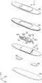
图1是示出本发明的实施方式的生物传感器的构成的立体图。FIG. 1 is a perspective view showing the configuration of a biosensor according to an embodiment of the present invention.
图2是图1的分解立体图。FIG. 2 is an exploded perspective view of FIG. 1 .
图3是图1的I-I剖视图。Fig. 3 is an I-I sectional view of Fig. 1 .
图4是示出传感器部的构成的俯视图。FIG. 4 is a plan view showing the configuration of a sensor unit.
图5是图4的传感器部的一部分的分解立体图。FIG. 5 is an exploded perspective view of a part of the sensor unit in FIG. 4 .
图6是示出图4的传感器部的布局的说明图。FIG. 6 is an explanatory diagram showing the layout of the sensor unit in FIG. 4 .
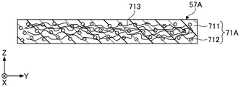
图7是图4的II-II局部剖视图。FIG. 7 is a partial cross-sectional view along line II-II of FIG. 4 .
图8是示出第一导电性粘合带以及第二导电性粘合带的另一构成的一个例子的图。FIG. 8 is a diagram showing an example of another configuration of the first conductive adhesive tape and the second conductive adhesive tape.
图9是示出第一导电性粘合带以及第二导电性粘合带的另一构成的一个例子的图。FIG. 9 is a diagram showing an example of another configuration of the first conductive adhesive tape and the second conductive adhesive tape.
图10是示出将生物传感器粘贴于生物(被测体)的皮肤的状态的说明图。FIG. 10 is an explanatory view showing a state where the biosensor is attached to the skin of a living being (subject).
图11是3点弯曲试验的说明图。Fig. 11 is an explanatory diagram of a 3-point bending test.
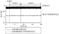
图12是示出实施例1的生物传感器的时间与电压的关系的图。FIG. 12 is a graph showing the relationship between time and voltage of the biosensor of Example 1. FIG.
图13是示出实施例2的生物传感器的时间与电压的关系的图。FIG. 13 is a graph showing the relationship between time and voltage of the biosensor of Example 2. FIG.
图14是示出实施例3的生物传感器的时间与电压的关系的图。FIG. 14 is a graph showing the relationship between time and voltage of the biosensor of Example 3. FIG.
图15是示出实施例4的生物传感器的时间与电压的关系的图。FIG. 15 is a graph showing the relationship between time and voltage of the biosensor of Example 4. FIG.
图16是示出实施例5的生物传感器的时间与电压的关系的图。FIG. 16 is a graph showing the relationship between time and voltage of the biosensor of Example 5. FIG.
图17是示出实施例6的生物传感器的时间与电压的关系的图。FIG. 17 is a graph showing the relationship between time and voltage of the biosensor of Example 6. FIG.
图18是示出比较例1的生物传感器的时间与电压的关系的图。FIG. 18 is a graph showing the relationship between time and voltage of the biosensor of Comparative Example 1. FIG.
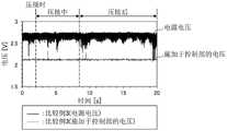
图19是示出比较例2的生物传感器的时间与电压的关系的图。FIG. 19 is a graph showing the relationship between time and voltage of the biosensor of Comparative Example 2. FIG.
图20是示出比较例3的生物传感器的时间与电压的关系的图。FIG. 20 is a graph showing the relationship between time and voltage of the biosensor of Comparative Example 3. FIG.
具体实施方式Detailed ways
以下,对于本发明的实施方式详细进行说明。需要说明的是。为了容易理解说明,在各附图中对于相同的构成元件赋予相同的附图标记,省略重复的说明。另外,有时附图中的各部件的比例尺与实际不同。在本说明书中,使用3轴方向(X轴方向、Y轴方向、Z轴方向)的3维正交坐标系,将生物传感器的宽度方向设定为X轴方向,将长度方向设定为Y轴方向,将高度方向(厚度方向)设定为Z轴方向。将生物传感器粘贴于生物(被测体)侧(粘贴侧)的相反方向设定为+Z轴方向,将粘贴于生物(被测体)侧(粘贴侧)设定为-Z轴方向。在以下的说明中,为了便于说明,将+Z轴方向侧称为上侧或上,将-Z轴方向侧称为下侧或下,但是其不代表普遍的上下关系。在本说明书中,表示数值范围的波浪线“~”在没有特别规定的情况下,表示作为下限值及上限值包括其前后记载的数值。Hereinafter, embodiments of the present invention will be described in detail. It should be noted. In order to facilitate understanding of the description, the same reference numerals are assigned to the same constituent elements in the respective drawings, and overlapping descriptions are omitted. In addition, the scale of each member in the drawings may be different from the actual scale. In this specification, a 3-dimensional orthogonal coordinate system in 3-axis directions (X-axis direction, Y-axis direction, and Z-axis direction) is used, and the width direction of the biosensor is set as the X-axis direction, and the length direction is set as the Y-axis direction. Axis direction, set the height direction (thickness direction) to the Z-axis direction. Set the opposite direction of the biosensor pasted on the biological (subject) side (pasted side) as the +Z-axis direction, and set the side pasted on the biological (subject) side (pasted side) as the -Z-axis direction. In the following description, for convenience of description, the side in the +Z axis direction is referred to as the upper side or upper side, and the side in the −Z axis direction is referred to as the lower side or lower, but this does not represent a general up-down relationship. In this specification, the wavy line "-" which shows a numerical range shows that the numerical value described before and after it is included as a lower limit value and an upper limit value, unless otherwise specified.
<生物传感器><biosensor>
对本实施方式的生物传感器进行说明。在本实施方式中,作为一个例子,对于与生物接触而进行生物信息的测定的粘贴型生物传感器的情况进行说明。需要说明的是,生物是指,人体(人)以及牛、马、猪、鸡、狗和猫等的动物等。生物传感器粘贴于生物的一部分(例如,皮肤、头皮或额头等)。生物传感器可以应用于生物,其中优选应用于人体。The biosensor of this embodiment will be described. In this embodiment, as an example, a case of an adhesive biosensor that is in contact with a living thing and measures biological information will be described. In addition, living things refer to human bodies (humans) and animals such as cows, horses, pigs, chickens, dogs, and cats. The biosensor is attached to a part of a living thing (for example, skin, scalp or forehead, etc.). Biosensors can be applied to living things, and are preferably applied to human bodies.
图1是示出本实施方式的生物传感器的构成的立体图,图2是图1的分解立体图,图3是图1的I-I剖视图。如图1所示,生物传感器1是在俯视中形成为大致椭圆状的板状(片状)部件。如图2以及图3所示,生物传感器1具有生物用粘合层10、发泡片20、壳体30、电极40以及传感器部50,其构成为自生物用粘合层10侧朝向壳体30侧依次层叠生物用粘合层10、发泡片20以及壳体30。生物用粘合层10、发泡片20以及壳体30在俯视中具有大致相同的外形形状。电极40设于生物用粘合层10的向皮肤2的粘贴侧(-Z轴方向)的面上。传感器部50设置于生物用粘合层10之上,其容纳于由发泡片20及壳体30形成的收纳空间S内。1 is a perspective view showing the configuration of a biosensor according to this embodiment, FIG. 2 is an exploded perspective view of FIG. 1 , and FIG. 3 is a cross-sectional view taken along line I-I of FIG. 1 . As shown in FIG. 1 , the biosensor 1 is a plate-shaped (sheet-shaped) member formed in a substantially elliptical shape in plan view. As shown in FIG. 2 and FIG. 3 , the biosensor 1 has an
[生物用粘合层][Adhesive layer for biological use]
如图3所示,生物用粘合层10具有基材11、粘贴用粘合层12、以及传感器用粘合层13。As shown in FIG. 3 , the
(基材)(Substrate)
如图3所示,基材11以发泡片20以及壳体30侧的面露出的方式设于粘贴用粘合层12。基材11的宽度方向(X轴方向)的两侧的外形形状与发泡片20以及壳体30的宽度方向(X轴方向)的两侧的外形形状大致相同。基材11的长度(Y轴方向)形成为比发泡片20以及壳体30的长度(Y轴方向)短。As shown in FIG. 3 , the
基材11可以使用具有适当的伸缩性、可挠性以及韧性的可挠性树脂形成。作为形成基材11的材料,例如,可以使用聚对苯二甲酸乙二醇酯(PET)、聚对苯二甲酸丁二醇酯、聚对苯二甲酸丙二醇酯、聚萘二甲酸乙二醇酯、聚萘二甲酸丁二醇酯等聚酯类树脂;聚丙烯酸、聚甲基丙烯酸、聚丙烯酸甲酯、聚甲基丙烯酸甲酯(PMMA)、聚甲基丙烯酸乙酯、聚丙烯酸丁酯等丙烯酸类树脂;聚乙烯、聚丙烯等聚烯烃类树脂;聚苯乙烯、酰亚胺改性聚苯乙烯、丙烯腈·丁二烯·苯乙烯(ABS)树脂、酰亚胺改性ABS树脂、苯乙烯·丙烯腈共聚物(SAN)树脂、丙烯腈·乙烯-丙烯-二烯·苯乙烯(AES)树脂等聚苯乙烯系树脂;聚酰亚胺系树脂;聚氨酯系树脂;有机硅类树脂;聚氯乙烯、化乙烯-醋酸乙烯共聚树脂等聚氯乙烯系树脂等的热可塑性树脂。在这些之中,特别优选使用聚烯烃类树脂、PET。这些热可塑性树脂具有防水性(水分透过性较低)。因此,基材11通过使用这些热可塑性树脂形成,在生物传感器1粘贴于生物的皮肤2的状态下,能够抑制自皮肤2产生的汗或水蒸气通过基材11而进入传感器部50的挠性基板51侧。The
由于基材11在其上表面设置传感器部50,因此优选形成为平板状。Since the
基材11的厚度可以适当任意选择,例如,优选为1μm~300μm,更优选为5μm~100μm,进一步优选为10μm~50μm。The thickness of the
(粘贴用粘合层)(adhesive layer for pasting)
如图3所示,粘贴用粘合层12设于基材11的粘贴侧(-Z轴方向)的下表面,是与生物接触的层。优选粘贴用粘合层12具有透湿性。能够使自生物传感器1所粘贴的皮肤2产生的水蒸气等经由粘贴用粘合层12进入发泡片20。而且,如后所述,由于发泡片20具有气泡构造,因此能够使水蒸气经由壳体用粘合层22向生物传感器1的外部放出。由此,能够在安装了生物传感器1的皮肤2与粘贴用粘合层12的界面处,抑制汗或水蒸气积存。其结果,能够抑制因在皮肤2与粘贴用粘合层12的界面处积存的水分而导致粘贴用粘合层12的粘合力变弱,从而生物传感器1自皮肤剥离。As shown in FIG. 3 , the
优选粘贴用粘合层12具有压敏胶粘性。通过粘贴用粘合层12具有压敏胶粘性,能够通过将生物传感器1按压于生物的皮肤2而容易地粘贴于皮肤2。The
作为粘贴用粘合层12的材料,只要为具有压敏胶粘性的材料即可,不特别限定,可以举出具有生物相容性的材料等。作为形成粘贴用粘合层12的材料,可以举出丙烯酸类压敏胶粘剂、硅类压敏胶粘剂等。优选可以举出丙烯酸类压敏胶粘剂。The material of the sticking
优选丙烯酸类压敏胶粘剂作为主成分含有丙烯酸聚合物。丙烯酸聚合物可以作为压敏胶粘成分起作用。作为丙烯酸聚合物,可以使用将作为主成分包含丙烯酸异壬酯、丙烯酸甲氧基乙酯等的(甲基)丙烯酸酯,作为任意成分包含能够与丙烯酸等的(甲基)丙烯酸酯共聚的单体的单体成分聚合后的聚合物。It is preferable that the acrylic pressure-sensitive adhesive contains an acrylic polymer as a main component. Acrylic polymers can function as pressure sensitive adhesive components. As the acrylic polymer, a (meth)acrylate containing isononyl acrylate, methoxyethyl acrylate, etc. A polymer after polymerization of the monomer components of the body.
优选丙烯酸类压敏胶粘剂还含有羧酸酯。羧酸酯作为使烯酸聚合物的压敏胶粘力降低,从而对粘贴用粘合层12的压敏胶粘力进行调整的压敏胶粘力调整剂起作用。羧酸酯可以使用能够与丙烯酸聚合物相溶的羧酸酯。作为羧酸酯,可以使用三脂肪酸甘油酯等。Preferably, the acrylic pressure sensitive adhesive also contains a carboxylate. The carboxylate ester functions as a pressure-sensitive adhesive force adjuster that lowers the pressure-sensitive adhesive force of the alkene polymer to adjust the pressure-sensitive adhesive force of the
丙烯酸类压敏胶粘剂可以根据需要含有交联剂。交联剂是使丙烯酸聚合物交联的交联成分。作为交联剂,可以举出多异氰酸酯化合物(多官能异氰酸酯化合物)、环氧化合物、三聚氰胺化合物、过氧化物、尿素化合物、金属醇盐化合物、金属螯合物、金属盐化合物、碳化二亚胺化合物、噁唑啉化合物、氮丙啶化合物、胺化合物等。在这些之中,优选多异氰酸酯化合物。这些交联剂可以单独使用,也可以并用。The acrylic pressure-sensitive adhesive may contain a crosslinking agent as needed. The crosslinking agent is a crosslinking component that crosslinks the acrylic polymer. Examples of the crosslinking agent include polyisocyanate compounds (polyfunctional isocyanate compounds), epoxy compounds, melamine compounds, peroxides, urea compounds, metal alkoxide compounds, metal chelate compounds, metal salt compounds, carbodiimide Compounds, oxazoline compounds, aziridine compounds, amine compounds, etc. Among these, polyisocyanate compounds are preferable. These crosslinking agents may be used alone or in combination.
优选粘贴用粘合层12具有优异的生物相容性。例如,对粘贴用粘合层12进行角质剥离试验时,优选角质剥离面积率为0%~50%,更优选为1%~15%。若角质剥离面积率为0%~50%的范围内,则即使将粘贴用粘合层12粘贴于皮肤2,也能够抑制皮肤2的负荷。The
优选粘贴用粘合层12的透湿度为300(g/m2·day)以上,更优选为600(g/m2·day)以上,进一步优选为1000(g/m2·day)以上。另外,粘贴用粘合层12的透湿度为10000(g/m2·day)以下。若粘贴用粘合层12的透湿度为300(g/m2·day)以上,则即使将粘贴用粘合层12粘贴于皮肤2,由于能够使自皮肤2产生的汗等适当自基材11朝向外部透过,因此能够降低皮肤2的负担。The moisture permeability of the sticking
粘贴用粘合层12的厚度可以适当任意选择,优选为10μm~300μm。若粘贴用粘合层12的厚度为10μm~300μm,则可以实现生物传感器1的薄型化。The thickness of the
传感器用粘合层13粘贴于基材11的上表面,是将基材11与传感器部50的挠性基板51粘接的层。作为形成传感器用粘合层13的材料,优选为具有压敏胶粘性的材料,可以使用与粘贴用粘合层12同样的材料,优选使用丙烯酸类压敏胶粘剂。The
传感器用粘合层13的厚度可以适当任意设定,优选为10μm~300μm。若传感器用粘合层13的厚度为10μm~300μm,则可以实现生物传感器1的薄型化。The thickness of the
[发泡片][foam sheet]
发泡片20具有发泡粘贴层21和设于其上表面的壳体用粘合层22。The
(发泡粘贴层)(foam adhesive layer)
如图3所示,发泡粘贴层21具有发泡基材211、以及设于发泡基材211的生物侧(-Z轴方向)的面的基材用粘合层212。需要说明的是,在发泡基材211与粘贴用粘合层12的粘接充分的情况下,发泡粘贴层21可以不具有基材用粘合层212,而是使发泡基材211粘接于粘贴用粘合层12。As shown in FIG. 3 , the
((发泡基材))((foam base material))
发泡基材211可以使用具有可挠性、防水性以及透湿性的、连续气泡、独立气泡或半独立气泡的发泡构造的发泡体来形成。由此,生物传感器1能够使基于自被粘贴的生物产生的汗等的水蒸气经由发泡基材211向生物传感器1的外部放出。The
作为形成发泡基材211的材料,例如,可以使用聚氨酯类树脂、聚苯乙烯类树脂、聚烯烃类树脂、硅类树脂、丙烯酸类树脂、氯乙烯类树脂、聚酯类树脂等的热可塑性树脂。在这些之中,优选为聚酯类树脂,适合使用PET。As the material forming the
发泡基材211的厚度可以适当选择,例如可以设定为0.5mm~1.5mm。The thickness of the
((基材用粘合层))((Adhesive layer for substrate))
如图3所示,基材用粘合层212设置为粘贴于发泡基材211的下表面,具有将基材11与发泡基材211粘接的功能。As shown in FIG. 3 , the base
优选基材用粘合层212具有透湿性。能够使自粘贴有生物传感器1的皮肤2产生的水蒸气等经由基材用粘合层212进入发泡基材211。而且,如上所述,由于发泡基材211具有气泡构造,因此能够使水蒸气经由壳体用粘合层22向生物传感器1的外部放出。由此,能够在安装有生物传感器1的皮肤2与粘贴用粘合层12的界面处抑制汗或水蒸气积存。其结果,能够抑制粘贴用粘合层12的粘合力因积存于皮肤2与粘贴用粘合层12的界面的水分而变弱,从而生物传感器1自皮肤2剥离。It is preferable that the
作为形成基材用粘合层212的材料,优选为具有压敏胶粘性的材料,可以使用与粘贴用粘合层12相同的材料。作为形成基材用粘合层212的材料,优选使用丙烯酸类压敏胶粘剂。The material for forming the
优选基材用粘合层212的透湿度为1(g/m2·day)以上,更优选为10(g/m2·day)以上。另外,基材用粘合层212的透湿度为10000(g/m2·day)以下。若基材用粘合层212的透湿度为10(g/m2·day)以上,则在将粘贴用粘合层12粘贴于皮肤2时,能够使自生物用粘合层10传来的汗等朝向外部透过,能够抑制皮肤2的负荷。The moisture permeability of the base
基材用粘合层212的厚度可以适当任意设定,优选为10μm~300μm。若基材用粘合层212的厚度为10μm~300μm,则可以实现生物传感器1的薄型化。The thickness of the base
(壳体用粘合层)(Adhesive layer for housing)
如图3所示,壳体用粘合层22在粘贴于发泡基材211的上表面的状态下进行设置。壳体用粘合层22粘贴于发泡基材211的上表面中的、与壳体30的粘贴侧(-Y轴方向)的平坦面对应的位置,具有将发泡基材211与壳体30粘接的功能。As shown in FIG. 3 , the case
作为形成壳体用粘合层22的材料,可以使用硅类粘合剂、硅胶带等。As a material for forming the case
优选壳体用粘合层22具有透湿性。由于发泡基材211具有连续气泡构造,因此可以将经由壳体用粘合层22进入的水蒸气向生物传感器1的外部放出。It is preferable that the case
壳体用粘合层22的厚度可以适当设定,例如可以设定为0.5mm~1.5mm。The thickness of the case
优选壳体用粘合层22的透湿度为65(g/m2·day)~4000(g/m2·day),更优选为90(g/m2·day)~2000(g/m2·day),进一步优选为800(g/m2·day)~1700(g/m2·day),最优选为850(g/m2·day)~1660(g/m2·day)。若壳体用粘合层22的透湿度为上述优选范围内,则能够缓和设于基材11的粘贴侧(-Z轴方向)的面的粘贴用粘合层12与皮肤2的界面的应力,从而能够抑制生物传感器1自皮肤2剥离。The moisture permeability of the
(壳体)(case)
如图3所示,壳体30与发泡片20的上表面粘接。壳体30在长度方向(Y轴方向)的中央部分具有朝向生物传感器1的高度方向(+Z轴方向)突出为大致圆顶状的突出部31。另外,壳体30的下表面(粘贴侧的面)形成为平坦。在突出部31的内侧(粘贴侧)形成用于收纳传感器部50的收纳空间S。As shown in FIG. 3 , the
作为形成壳体30的材料,例如可以使用硅橡胶、氟橡胶、聚氨酯橡胶等的具有柔软性的材料。能够保护配置于壳体30的收纳空间S的传感器部50,并且能够吸收自上表面侧施加于生物传感器1的冲击而缓和施加于传感器部50的冲击。As a material forming the
优选壳体30的突出部31的上表面以及侧壁的厚度比设于壳体30的长度方向L的两端侧的平坦部32a以及32b的厚度厚。由此,能够将突出部31的柔软性设定为给比平坦部32a以及32b的柔软性低,从而能过够自施加于生物传感器1的外力保护传感器部50。The thickness of the upper surface and the side wall of the protruding
突出部31的上表面以及侧壁的厚度为1.5mm~3mm,优选平坦部32a以及32b的厚度为0.5mm~1mm。The thickness of the upper surface and the side wall of the protruding
由于厚度较薄的平坦部32a以及32b与突出部31相比柔软性较高,因此在将生物传感器1粘贴于皮肤2的情况下,能够易于跟随基于伸展、弯曲以及扭曲等的体动的皮肤2的表面的变形而进行变形。由此,能够在皮肤2的表面变形的情况下缓和施加于平坦部32a以及32b的应力,从而能够使生物传感器1难以自皮肤2剥离。Since the thinner
优选平坦部32a以及32b的外周部具有朝向端部厚度逐渐变小的形状。由此,能够进一步提高平坦部32a以及32b的外周部的柔软性,与不使平坦部32a以及32b的外周部的厚度变薄的情况相比,能够使生物传感器1粘贴于皮肤2的情况的安装感提高。It is preferable that the outer peripheral parts of the
(电极)(electrode)
如图3所示,电极40粘贴于设于基材11的粘贴侧(-Z轴方向)即下表面的粘贴用粘合层12的下表面。在生物传感器1粘贴于皮肤2时,通过电极40与皮肤2接触,能够检测生物信号。生物信号例如是表示心电波形、脑电波、脉搏等的电信号。需要说明的是,电极40可以在以能够与皮肤接触的方式露出的状态下埋设于基材11中。As shown in FIG. 3 , the
电极40可以使用将包括导电性高分子和粘合剂树脂的导电性组成物的固化物、金属、合金等形成为片状的电极片。As the
作为导电性高分子,例如可以使用聚噻吩类导电性高分子、聚苯胺类导电性高分子、聚吡咯类导电性高分子、聚乙炔类导电性高分子、聚亚苯基类导电性高分子及其衍生物、以及这些的复合体等。这些可以一种单独使用,也可以两种以上并用。在这些之中,优选在聚噻吩中作为掺杂剂掺杂了聚苯胺的复合体。在聚噻吩与聚苯胺的复合体之中,从与生物的接触阻抗更低,具有较高导电性这点出发,更优选在聚3、4-亚乙二氧基噻吩(PEDOT)中掺杂了聚苯乙烯磺酸(聚4-苯乙烯磺酸盐;PSS)的PEDOT/PSS。As the conductive polymer, for example, polythiophene-based conductive polymers, polyaniline-based conductive polymers, polypyrrole-based conductive polymers, polyacetylene-based conductive polymers, polyphenylene-based conductive polymers, and polyphenylene-based conductive polymers can be used. And its derivatives, and complexes of these, etc. These may be used alone or in combination of two or more. Among these, a composite in which polyaniline is doped as a dopant in polythiophene is preferable. Among the complexes of polythiophene and polyaniline, it is more preferable to dope poly(3,4-ethylenedioxythiophene (PEDOT)) in view of the lower contact impedance with organisms and higher conductivity. PEDOT/PSS of polystyrene sulfonic acid (poly-4-styrene sulfonate; PSS).
另外,电极40可以在以能够与生物接触的方式露出的状态下埋设于粘贴用粘合层12的下表面中。In addition, the
而且,电极40可以在与皮肤2的接触面具有多个贯通孔。由此,电极40能够在粘贴于粘贴用粘合层12的状态下,自贯通孔使粘贴用粘合层12在粘贴侧露出,从而能够提高电极40与皮肤2的紧贴性。Furthermore, the
(传感器部)(Sensor Department)
图4是示出传感器部50的构成的俯视图,图5是传感器部50的一部分的分解立体图。需要说明的是,图4中的虚线示出了壳体30的外径。如图4以及图5所示,传感器部50具有搭载有用于取得生物信息的各种部件的挠性基板51、传感器主体52、在传感器主体52的长度方向分别与传感器主体52连接的布线53a和53b、电池54、正电极图案(第一电极部)55、负电极图案(第二电极部)56、以及导电性粘合带57。在传感器部50的垫片部522a与垫片部522b之间,自垫片部522a侧至垫片部522b侧依次层叠有正电极图案55、导电性粘合带57、电池54、导电性粘合带57以及负电极图案56。需要说明的是,在本实施方式中,虽然将电池54的正极端子设定为-Z轴方向,将负极端子设定为+Z轴方向,但是也可以相反,可以将正极端子设定为+Z轴方向,将负极端子设定为-Z轴方向。FIG. 4 is a plan view showing the configuration of the
挠性基板51是树脂基板,在挠性基板51中,传感器主体52与布线53a和53b一体形成。The
如图3所示,布线53a和53b的一端分别与电极40连结。如图4所示,布线53a的另一端与沿传感器主体52的外周搭载于部件搭载部521的开关等连接。布线53b的另一端也与布线53a相同,与搭载于部件搭载部521的开关等连接。需要说明的是,布线53a以及53b可以形成于挠性基板51的表面侧以及背面侧的布线层的任一者。As shown in FIG. 3, one ends of the
如图4所示,传感器主体52具有作为控制部的部件搭载部521、以及电池安装部522。As shown in FIG. 4 , the sensor
部件搭载部521具有用于对自生物取得的生物信号进行处理而生成生物信号数据的CPU以及集成电路、用于启动生物传感器1的开关、用于存储生物信号的闪存、以及发光元件等搭载于挠性基板51的各种部件。需要说明的是,省略各种部件的电路例。部件搭载部521通过自安装于电池安装部522的电池54供给的电力进行动作。The
部件搭载部521通过有线或无线向用于确认初始动作的动作确认机器、用于读取来自生物传感器1的生物信息的读取机器等的外部装置进行发送。The
电池安装部522向搭载于部件搭载部521的集成电路等供给电力。如图5所示,在电池安装部522中安装电池54。The
在图6中示出了表示图4的传感器部50的布局的说明图。如图6所示,电池安装部522配置于布线53a与部件搭载部521之间,其具有垫片部522a和522b、以及缩颈部522c。FIG. 6 is an explanatory diagram showing the layout of the
如图6所示,垫片部522a设于布线53a和部件搭载部521之间,位于电池54的正极端子侧,具有供正极端子连接的正电极图案55。As shown in FIG. 6 , the
如图6所示,垫片部522b相对于垫片部522a在长度方向的正交方向(图3的上侧方向)上自垫片部522a离开规定间隔设置。垫片部522b位于电池54的负极端子(第二端子)侧,具有供负极端子连接的负电极图案56。As shown in FIG. 6 , the
如图6所示,缩颈部522c配置于垫片部522a和522b之间,将垫片部522a和522b彼此连结。As shown in FIG. 6 , the
如图5所示,电池54配置于正电极图案55和负电极图案56之间。电池54具有正极端子以及负极端子,可以使用公知的电池。作为电池54,例如,可以使用CR2025等的纽扣型电池。As shown in FIG. 5 , the
正电极图案55位于电池54的正极端子侧,与正极端子连接。如图6所示,正电极图案55具有角部取圆角的矩形。The
负电极图案56位于电池54的负极端子侧,与负极端子连接。如图6所示,负电极图案56具有与电池54的负极端子的圆形形状的大小大致对应的形状。负电极图案56的直径例如与电池54的直径相等,具有与正电极图案55的对角线的长度大致相等的大小。The
导电性粘合带57是具有导电性的粘合剂,其分别配置于电池54与正电极图案55之间、以及电池54与负电极图案56之间。需要说明的是,导电性粘合带一般也称为导电性粘合片、导电性粘合薄膜等。The conductive adhesive tape 57 is an adhesive having conductivity, and is arranged between the
设定使重量33g的铁球自高度30cm垂直落下而对表面施加了载荷时的、电阻值的变动幅度的绝对值为1.60Ω以下。本申请发明人们着眼于,通过抑制规定的载荷施加于导电性粘合带57的表面时的电阻值的变动,即使载荷施加于导电性粘合带57,也能够抑制导电通路的大小的变化。并且,本申请发明人发现,在导电性粘合带57的电阻值的变动幅度的绝对值为1.60Ω以下时,即使规定的载荷施加于导电性粘合带57,也能够抑制导电通路的大小的变化,导通稳定。When an iron ball weighing 33 g is dropped vertically from a height of 30 cm and a load is applied to the surface, the absolute value of the fluctuation range of the resistance value is set to be 1.60Ω or less. The inventors of the present application focused on suppressing changes in the resistance value when a predetermined load is applied to the surface of the conductive adhesive tape 57 , so that even when a load is applied to the conductive adhesive tape 57 , changes in the size of the conductive path can be suppressed. Furthermore, the inventors of the present application found that when the absolute value of the fluctuation range of the resistance value of the conductive adhesive tape 57 is 1.60Ω or less, even if a predetermined load is applied to the conductive adhesive tape 57, the size of the conductive path can be suppressed. changes, the conduction is stable.
优选导电性粘合带57将每单位弯曲挠曲量的弯曲载荷设定为0.035N/cm以下。若将使电池与正电极图案55或负电极图案56接合的导电性粘合带57的刚性设定为较小,每单位弯曲挠曲量的弯曲载荷为规定值以下,则即使载荷施加于导电性粘合带57,也能够抑制导电通路的大小的变化,导电性粘合带57的电阻变动被抑制,能够使导通稳定。The conductive adhesive tape 57 preferably has a bending load per unit bending deflection of 0.035 N/cm or less. If the rigidity of the conductive adhesive tape 57 for bonding the battery to the
这里,每单位弯曲挠曲量的弯曲载荷可以通过使用依据JIS K7171的3点弯曲试验,计算每单位弯曲挠曲量的弯曲载荷来求得。具体而言,将导电性粘合带57设定为规定的尺寸(例如,宽度2cm×长度15cm),用PET薄膜(厚度:38μm)包夹导电性粘合带57的两面来进行加强,制作用PET薄膜包夹导电性粘合带57的层叠体。使用层叠体进行三点弯曲试验,在将挠曲量(单位:cm)作为X轴、将载荷(单位:N)作为Y轴时得到的挠曲量-载荷曲线中,将挠曲量1cm以下视为初始斜度,计算层叠体的斜度。将所得层叠体的斜度作为导电性粘合带57的每单位弯曲挠曲量的弯曲载荷求出。另外,在制作多个(例如,9个)层叠体时,可以将每单位弯曲挠曲量的弯曲载荷设定为多个(例如,9个)层叠体的每单位弯曲挠曲量的弯曲载荷的平均值。需要说明的是,设置导电性粘合带57的两个支点间距离、压头的下降(压缩)速度可以根据层叠体的大小等适当选择,例如,在导电性粘合带57的尺寸为宽度2cm×长度15cm时,支点间距离设定为5cm,压缩速度设定为1cm/min。Here, the bending load per unit bending deflection can be obtained by calculating the bending load per unit bending deflection using a 3-point bending test based on JIS K7171. Specifically, the conductive adhesive tape 57 is set to a predetermined size (for example,
导电性粘合带57包括配置于电池54的正极端子与正电极图案55之间的第一导电性粘合带57A、以及配置于电池54的负极端子与负电极图案56之间的第二导电性粘合带57B。需要说明的是,在以下的说明中,有时将第一导电性粘合带57A以及第二导电性粘合带57B一并仅称为导电性粘合带57。The conductive adhesive tape 57 includes a first conductive
图7是图4的II-II局部剖视图。如图7所示,第一导电性粘合带57A设于电池54的正极端子和正电极图案55之间,将正极端子和正电极图案55电连接。第二导电性粘合带57B设于电池54的负极端子和负电极图案56之间,将第二端子和负电极图案56电连接。FIG. 7 is a partial cross-sectional view along line II-II of FIG. 4 . As shown in FIG. 7 , the first conductive
第一导电性粘合带57A由粘合剂层71A构成,第二导电性粘合带57B由粘合剂层71B构成。第一导电性粘合带57A以及第二导电性粘合带57B均为粘合剂层71A以及71B的两面成为粘合面的、所谓双面粘合型导电性粘合带。需要说明的是,有时将粘合剂层71A以及71B的表面称为粘合面。另外,第一导电性粘合带57A以及第二导电性粘合带57B是不具有金属箔等的导电性基材的、所谓无基材导电性双面粘合带。The first conductive
〔粘合剂层〕〔Adhesive layer〕
粘合剂层71A以及71B提供导电性粘合带的粘合面,并且具有导电性(电传导性)。若粘合剂层71A以及71B的粘合面背粘贴于导体等的被粘体,则确保被粘体与粘合剂层71A以及71B之间的电导通。The
如图7所示,粘合剂层71A以及71B具有粘合树脂711、以及导电性微粒子(导电性填充物)712。需要说明的是,粘合剂层71A以及71B在不损害导电性粘合带57的目的的范围内,可以含有其他成分(添加剂)。As shown in FIG. 7 ,
优选粘合剂层71A以及71B的厚度为20μm~80μm,更优选为30μm~70μm,进一步优选为35μm~60μm。若粘合剂层71A以及71B的厚度为上述优选范围内,则能够将导电性粘合带57设定为较薄,从而能够提高柔软性。The thickness of the
(粘合树脂)(adhesive resin)
粘合树脂711具有确保粘合剂层71A以及71B的粘合力等的功能。粘合树脂711使用粘合性聚合物形成。作为粘合性聚合物,例如可以举出丙烯酸类聚合物、硅类聚合物、聚氨酯类聚合物、橡胶类聚合物、乙烯基烷基醚类聚合物、聚酯类聚合物、聚酰胺类聚合物、氟类聚合物、环氧基类聚合物等。在这些之中,从聚合物的设计的容易性、粘合力的易调整性、导电性粒子的分散性的确保等的点出发,优选使用丙烯酸类聚合物。需要说明的是,粘合性聚合物可以单独使用或组合两种以上使用。在以下的说明中,对于粘合性聚合物由丙烯酸类聚合物组成或包括丙烯酸类聚合物的情况进行说明。The
优选粘合树脂711的含有量(下限值)相对于粘合剂层71A以及71B的总质量(100质量%)为20质量%以上,更优选为25质量%以上,进一步优选为30质量%以上。另外,优选粘合树脂711的含有量(上限值)相对于粘合剂层71A以及71B的总质量(100质量%)为60质量%以下,更优选为55质量%以下。The content (lower limit) of the
在粘合树脂711包括丙烯酸类聚合物而形成的情况下,优选丙烯酸类聚合物的含有量(下限值)相对于粘合树脂711的总质量(100质量%)为50质量%以上,更优选为60质量%以上。另外,优选丙烯酸类聚合物的含有量(上限值)相对于树脂成分的总质量(100质量%)为100质量%以下,更优选为90质量%以下。When the
作为丙烯酸类聚合物,虽然不特别限定,但是例如优选为将具有碳原子数为1~20的直链或支链状烷基的(甲基)丙烯酸烷基酯(以下,仅称为(甲基)丙烯酸烷基酯)、以及含极性基团单体作为单体成分而构成的丙烯酸类聚合物。需要说明的是,在本说明书中“(甲基)丙烯酸”是指,表示“丙烯酸”以及“异丁烯”中的、任一者或两者。The acrylic polymer is not particularly limited, but for example, an alkyl (meth)acrylate having a linear or branched alkyl group having 1 to 20 carbon atoms (hereinafter, simply referred to as (meth)acrylate) is preferable. Alkyl acrylate) and an acrylic polymer composed of polar group-containing monomers as monomer components. In addition, in this specification, "(meth)acrylic acid" means any one or both of "acrylic acid" and "isobutylene".
从能够进一步体现粘合树脂711的效果这点出发,优选丙烯酸类聚合物的重量平均分子量(Mw)为30万~100万,更优选为40万~80万。重量平均分子量(Mw)除了可以通过聚合引发剂或链转移剂的种类、其使用量、聚合时的温度、时间进行控制之外,还可以通过单体浓度、单体滴下速度等进行控制。需要说明的是,重量平均分子量例如可以通过凝胶渗透色谱(GPC)法进行测定。From the viewpoint that the effect of the
[导电性粒子][conductive particle]
如图7所示,导电性微粒子712在分散的状态下包含于粘合树脂711中。As shown in FIG. 7 , conductive
作为导电性微粒子712,使用金属粉等的具有导电性的粒子。作为形成导电性粒子的材料,例如,可以举出由镍、铁、铬、钴、铝、锑、钼、铜、银、铂、金等金属、它们的合金或氧化物、炭黑等碳材料等导电性材料构成的粒子(粉末);用导电性材料包覆聚合物珠、玻璃、陶瓷等粒子表面的包覆粒子等。另外,包覆粒子包括用其他种类的导电性材料包覆由导电性材料构成的粒子的表面而成的粒子。在这些之中,优选金属以及包覆粒子,作为金属,优选使用镍、银。As the conductive
导电性微粒子712的形状为球状、钉状(带刺栗子状)、片状(薄片状)、长丝状等,适当进行选择。在导电性微粒子712为球状的情况下,由于导电性微粒子712易于在粘合树脂711内均匀分散,因此易于确保粘合力,并且粘合剂层71中的基于导电性微粒子712的导电路容易形成。因此,优选导电性微粒子712的形状为球状。The shape of the conductive
优选导电性微粒子712的纵横比为1.0~1.5,更优选为1.0~1.1。需要说明的是,导电性微粒子712的纵横比例如可以通过扫描型电子显微镜(SEM)来测定。The aspect ratio of the conductive
优选导电性微粒子712的粒径d50比粘合剂层71A以及71B的厚度小。即,优选存在“粘合剂层71A以及71B的厚度>d50”的关系。d50是粒径分布中的50%累积值(中值粒径)。d50例如通过激光衍射·散射法来测定。需要说明的是,在粘合剂层71A以及71B中包含两种以上导电性微粒子712的情况下,根据将全部种类的导电性微粒子712混合后的分布计算d50。The particle sized50 of the conductive
通过d50存在上述关系,粘合剂层71A以及71B可以具有更高的导电性以及更优异的粘合性。在d50为粘合剂层71的厚度以上的情况下,半数以上的导电性微粒子712比粘合剂层71A以及71B的厚度大,在粘合剂层71A以及71B的表面形成突起。因此,担心粘合剂层71A以及71B与被粘体的接触面积降低,粘合性降低,同时担心外观不良。作为d50的具体的范围,优选为2μm~20μm,更优选为3μm~15μm,进一步优选为4μm~10μm。By having the above-mentioned relationship of d50 , the
优选导电性微粒子712的含有量的上限值相对于粘合剂层71A以及71B的总质量(100质量%)为70质量%以下,更优选为65质量%以下,进一步优选为60质量%以下。另外,优选导电性微粒子712的含有量的下限值为15质量%以上,更优选为20质量%以上,进一步优选为25质量%以上。若导电性微粒子712的含有量为上述优选范围内,则能够不使粘合剂层71A以及71B的粘合力降低,并且确保粘合剂层71A以及71B的导电性。The upper limit of the content of the conductive
如图8所示,粘合剂层71A以及71B可以作为导电性填充物包括导电性纤维713。As shown in FIG. 8, the
导电性纤维713具有导电性即可,可以使用公知的材料。作为导电性纤维713,可以使用金、银、铂、铜、镍、锡、锌、钯、氧化铟锡、硫化铜等的金属纤维、碳纳米管等的碳纤维、由导电性高分子构成的纤维、由使纤维状或粒状的导电性填充物分散的高分子构成的纤维、用导电性材料包覆纤维基材的表面的导电性包覆纤维。作为纤维基材,不论是导电性的有无,可以使用公知的纤维,例如,除了可以使用聚酯纤维、尼龙纤维、丙烯酸纤维、聚乙烯纤维、聚丙烯纤维、氯乙烯纤维、芳族聚酰胺纤维、聚砜纤维、聚醚纤维、聚氨酯纤维等的合成纤维之外,还可以使用棉、麻、丝绸等的天然纤维、醋酸纤维等的半合成纤维、人造丝、铜氨丝等的再生纤维。可以单独使用这些纤维的1种,也可以并用2种以上。作为包覆纤维基材的表面的导电性材料,可以举出金属、导电性高分子等。作为金属,可以使用与在金属纤维中使用的金属同样的金属。其中,从导电性、耐久性、柔软性等的观点出发,金属是优选的。作为包覆金属的方法,可以举出蒸镀、溅射、电解电镀、无电解电镀等。It is sufficient that the
优选导电性纤维713的纤维直径小于1.1μm,更优选为300nm~1.0μm,进一步优选为400nm~700nm。若导电性纤维713的含有量为上述优选范围内,则能够不使粘合剂层71A以及71B的粘合力降低,并且确保粘合剂层71的导电性。The fiber diameter of the
导电性纤维713的纤维长不特别限定,可以根据粘合剂层71A以及71B的种类、厚度、体积等适当选择。需要说明的是,导电性纤维713的纤维直径以及纤维长可以通过扫描型电子显微镜来测定。The fiber length of the
如图9所示,粘合剂层71A以及71B可以包括导电性基材。将在粘合剂层71A以及71B内中包括了导电性基材的导电性双面粘合带称为所谓带基材导电性双面粘合带。即,导电性粘合带57可以构成为在导电性基材714的两面分别设置粘合剂层71。As shown in FIG. 9, the
另外,粘合剂层71在不损害导电性粘合带57的目的的范围内,除了导电性纤维、导电性基材之外,例如可以包括中间层、底涂层等的其他层。In addition, the adhesive layer 71 may include, for example, other layers such as an intermediate layer and a primer layer in addition to the conductive fibers and the conductive substrate within the range that does not impair the purpose of the conductive adhesive tape 57 .
在将电池54安装于生物传感器1的情况下,在正电极图案55以及负电极图案56的整体上分别安装第一导电性粘合带57A以及第二导电性粘合带57B。并且,将电池54的正极端子以及负极端子通过第一导电性粘合带57A以及第二导电性粘合带57B分别粘贴于正电极图案55以及负电极图案56,从而电池54被安装于电池安装部522。需要说明的是,图4所示传感器主体52示出了使缩颈部522c弯曲,从而将电池54以包夹在正电极图案55与负电极图案56之间的状态安装于电池安装部522的状态。When the
如图3所示,对于生物传感器1,为了保护生物用粘合层10以及电极40,优选在粘贴面侧(-Z轴方向)粘贴剥离纸60,直至将生物传感器1粘贴于生物。通过在使用时,将剥离纸60自生物用粘合层10以及电极40剥离,能够维持生物用粘合层10的粘贴用粘合层12的粘合力。As shown in FIG. 3 , for the biosensor 1, in order to protect the
图10是示出将图1的生物传感器1粘贴于生物P的胸部的状态的说明图。例如,生物传感器1将长度方向(Y轴方向)对齐被测者P的胸骨,将一个电极40设定为上侧,将另一电极40设定为下侧而粘贴于被测者P的皮肤。生物传感器1通过由图3的粘贴用粘合层12进行的向被测者P的皮肤的粘贴,从而在电极40压接于被测者P的皮肤的状态下,通过电极40自被测者P取得心电图信号等的生物信号。生物传感器1将取得的生物信号数据存储于在部件搭载部521中搭载的闪存等的非易失性存储器中。FIG. 10 is an explanatory diagram showing a state where the biosensor 1 of FIG. 1 is attached to the chest of a living being P. As shown in FIG. For example, the biosensor 1 aligns the longitudinal direction (Y-axis direction) with the sternum of the subject P, sets one
如此,生物传感器1包括正电极图案55和负电极图案56、以及配置于这些电极图案与电池54之间的导电性粘合带57,设定导电性粘合带57在使重量33g的铁球自高度30cm垂直落下而对表面施加了载荷时的、电阻值的变动幅度的绝对值为1.60Ω以下。由此,导电性粘合带57在于其表面施加载荷时,通过将电阻变动抑制为规定值以下,从而能够具有稳定的导通。因此,对于生物传感器1,在生物传感器1的使用时即使产生向被测者的皮肤2的压接、体动等,由于能够抑制导电性粘合带57的电阻变动且能够抑制电阻上升,因此能够抑制自电池54向部件搭载部521的供给电压的降低。由此,通过抑制自电池54向部件搭载部521的供给电压的降低,从而能够自电池54向部件搭载部521稳定供给电压。In this way, the biosensor 1 includes a
因此,对于生物传感器1,即使在生物传感器1的使用时产生向被测者的皮肤的压接、体动等,也能够抑制部件搭载部521的动作停止,从而能够自皮肤2稳定测定生物信息。Therefore, in the biosensor 1, even if the subject's skin is pressed or moved when the biosensor 1 is used, the stoppage of the operation of the
另外,生物传感器1在传感器部50作为电极部包括正电极图案55以及负电极图案56,并且作为导电性粘合带57能够包括第一导电性粘合带57A以及第二导电性粘合带57B。在电池54的正极端子与负极端子以彼此相反方向设置的情况下,生物传感器1可以在电池54的正极端子与正电极图案55之间配置第一导电性粘合带57A,在电池54的负极端子与负电极图案56之间配置第二导电性粘合带57B。由此,生物传感器1可以形成在传感器部50的垫片部522a与垫片部522b之间依次层叠正电极图案55、第一导电性粘合带57A、电池54、第二导电性粘合带57B以及负电极图案56的层叠体。因此,在电池54为纽扣型电池等那样的正极端子与负极端子彼此相反方向配置的电池的情况下,生物传感器1能够将传感器部50小型地容纳于生物传感器1内,并且即使在使用时产生向被测者的皮肤的压接、体动等而载荷施加于壳体的内部,也能够抑制导电性粘合带57的电阻变动,并且能够抑制电阻的上升。In addition, the biosensor 1 includes a
而且,生物传感器1中,导电性粘合带57可以包括含有粘合树脂711和导电性微粒子712的粘合剂层71。通过使导电性粘合带57由粘合剂层71构成,导电性粘合带57的刚性主要依赖于粘合剂层71,从而能够容易使导电性粘合带57的每单位弯曲挠曲量的弯曲载荷下降。因此,对于生物传感器1,即使在生物传感器1的使用时产生向被测者的皮肤的压接、体动等而载荷施加于壳体的内部,也能够更容易地抑制导电性粘合带57的电阻变动。Furthermore, in the biosensor 1, the conductive adhesive tape 57 may include an adhesive layer 71 containing an
另外,对于生物传感器1,可以使导电性粘合带57构成为在粘合树脂711中不含有基材。由此,能够使粘合树脂711的柔软性更容易提高,从而能够将导电性粘合带57的刚性设定为较小。因此,对于导电性粘合带57,在其表面施加载荷时,其易于变形,从而能够更稳定地抑制导电性粘合带57的电阻变动。In addition, in the biosensor 1, the conductive adhesive tape 57 may be configured so that the
另外,生物传感器1可以使导电性粘合带57构成为包括导电性纤维。可以使多个导电性纤维彼此在粘合树脂711内易于接触且使多个导电性纤维彼此在粘合树脂711内分散。因此,对于生物传感器1,即使载荷是施加于导电性粘合带57的表面,导电性粘合带57也能够易于维持导电性,能够更稳定地抑制电阻变动。In addition, in the biosensor 1, the conductive adhesive tape 57 may be configured to include conductive fibers. The plurality of conductive fibers can be easily contacted in the
因此,优选生物传感器1将导电性粘合带57中包含的、导电性纤维的平均纤维直径设定为小于1.1μm。由此,能够不使粘合剂层71的粘合力降低,且确保粘合剂层71的导电性。因此,导电性粘合带57能够维持粘合力和导电性,并且能够更稳定地抑制电阻变动。Therefore, in the biosensor 1, it is preferable that the average fiber diameter of the conductive fibers included in the conductive adhesive tape 57 is set to be smaller than 1.1 μm. Accordingly, the electrical conductivity of the adhesive layer 71 can be ensured without reducing the adhesive force of the adhesive layer 71 . Therefore, the conductive adhesive tape 57 can maintain adhesive force and conductivity, and can more stably suppress fluctuations in resistance.
另外,生物传感器1可以将导电性粘合带57中包含的、粘合剂层71的厚度设定为20μm~80μm。由此,能够将导电性粘合带57设定为较薄,从而能够使导电性粘合带57的刚性变小,从而易于变形。另外,能够将导电性粘合带57设定为更薄。因此,对于导电性粘合带57,在其表面施加载荷时,能够进一步容易地抑制电阻变动,并且能够较薄地形成导电性粘合带57。In addition, in the biosensor 1 , the thickness of the adhesive layer 71 included in the conductive adhesive tape 57 can be set to 20 μm to 80 μm. Thereby, the electroconductive adhesive tape 57 can be set thin, and the rigidity of the electroconductive adhesive tape 57 can be made small, and it becomes easy to deform|transform. In addition, the conductive adhesive tape 57 can be set thinner. Therefore, when a load is applied to the surface of the conductive adhesive tape 57 , it is possible to more easily suppress the change in resistance, and the conductive adhesive tape 57 can be formed thinner.
如此,如上所述,生物传感器1能够自电池向控制部稳定供给电压,因此,例如能够适合应用于生物传感器等的保健用可佩戴设备。In this way, as described above, the biosensor 1 can stably supply voltage from the battery to the control unit, and therefore, can be suitably applied to health care wearable devices such as biosensors, for example.
需要说明的是,在本实施方式中,可以将第一导电性粘合带57A或第二导电性粘合带57B的、施加了规定条件的载荷时的电阻值的变动幅度的绝对值设定为1.60Ω以下。It should be noted that, in the present embodiment, the absolute value of the fluctuation range of the resistance value of the first conductive
在本实施方式中,可以仅在电池54的正极端子与正电极图案55之间、以及电池54的负极端子与负电极图案56之间的一者中配置导电性粘合带57,而在另一者中使用导电性胶粘剂等。In the present embodiment, the conductive adhesive tape 57 may be disposed only in one of the positive terminal of the
(实施例)(Example)
以下,示出实施例以及比较例而对实施方式进行更具体说明,但是实施方式不限于这些实施例以及比较例。Hereinafter, although an Example and a comparative example are shown and embodiment is demonstrated more concretely, embodiment is not limited to these Example and comparative example.
<实施例1><Example 1>
[导电性粘合带的准备][Preparation of conductive adhesive tape]
准备了导电性粘合带1(商品名“9707”、3M日本株式会社制)。导电性粘合带1是在粘合树脂中以使导电性微粒子(材质:Ag、平均粒径:5μm、填充率:56wt%)分散的状态包含导电性微粒子的粘合带,是不包含基材的无基材导电性粘合带。A conductive adhesive tape 1 (trade name "9707", manufactured by 3M Japan Co., Ltd.) was prepared. The conductive adhesive tape 1 is an adhesive tape that contains conductive fine particles (material: Ag, average particle diameter: 5 μm, filling rate: 56 wt %) in a dispersed state in an adhesive resin, and does not contain a base. substrate-free conductive adhesive tape.
(导电性粘合带的厚度的测定)(Measurement of Thickness of Conductive Adhesive Tape)
使用JIS B 7503中规定的千分表,测定了粘合剂层的厚度。将千分表的接触面设定为平面,将直径设定为5mm。使用宽度150mm的试验片,通过1/1000mm刻度的千分表在宽度方向以等间隔测定5点的厚度,将其测定结果的平均值设定为粘合剂层的厚度。由于导电性粘合带1由粘合剂层构成,因此将粘合剂层的厚度设定为导电性粘合带1的厚度。The thickness of the adhesive layer was measured using a dial gauge specified in JIS B 7503. Set the contact surface of the dial indicator as a flat surface and the diameter as 5mm. Using a test piece with a width of 150 mm, measure the thickness of 5 points at equal intervals in the width direction with a dial gauge with a scale of 1/1000 mm, and set the average value of the measurement results as the thickness of the adhesive layer. Since the conductive adhesive tape 1 is composed of an adhesive layer, the thickness of the adhesive layer is set to the thickness of the conductive adhesive tape 1 .
(每单位弯曲挠曲量的弯曲载荷的测定)(Determination of bending load per unit bending deflection)
将导电性粘合带1的尺寸设定为宽度2cm×长度15cm。用PET薄膜(厚度:38μm)包夹导电性粘合带1的两面来进行加强,制作了9个用PET薄膜包夹导电性粘合带1而层叠的试验片。使用试验片,按照依据JIS K7171的3点弯曲试验,使用小型测定装置(EZ-Test、岛津制作所),进行了23℃下的3点弯曲试验。在图11中示出了3点弯曲试验的一个例子。如图11所示,以试验片80的中央部分成为两个支点81之间的中间的方式,将试验片80设置于两个支点81之上,在试验片80的中央部分之上设置了压头82。将支点81彼此的距离L设定为5cm,将压头的下降(压缩)速度设定为1cm/min。使压头下降,使试验片80弯曲。将挠曲量(单位:cm)设定为X轴,将载荷(单位:N)设定为Y轴时,获得的挠曲量(X)-载荷(Y)曲线中,将挠曲量1cm以下视为初始斜度,计算试验片80的斜度。将获得的斜度设定为每单位弯曲挠曲量的弯曲载荷。每单位弯曲挠曲量的弯曲载荷设定为9个试验片80的每单位弯曲挠曲量的弯曲载荷的平均值。The size of the electroconductive adhesive tape 1 was set to width 2cm x length 15cm. Both sides of the conductive adhesive tape 1 were sandwiched and reinforced with a PET film (thickness: 38 μm), and nine test pieces were laminated by sandwiching the conductive adhesive tape 1 with the PET film. Using the test piece, a 3-point bending test at 23° C. was performed using a small measuring device (EZ-Test, Shimadzu Corporation) according to a 3-point bending test based on JIS K7171. An example of a 3-point bending test is shown in FIG. 11 . As shown in FIG. 11 , the
(电阻变动值的计算)(Calculation of resistance variation value)
导电性粘合带1的试验片的尺寸设定为宽度1cm×长度1cm,在于试验片中流过约50mA电流的状态下,使重量33g的铁球自导电性粘合带1的正上30cm的位置落下。通过铁球冲击试验片时的电压变动计算电阻变动,测定了峰值电阻值。通过峰值电阻值与落球前的电阻值的差,计算电阻变动值。在导电性粘合带的电阻变动值为1.60Ω以下的情况下,评价为导电性粘合带的电压稳定性良好(表1中,A记号),在导电性粘合带的电阻变动值超过1.60Ω的情况下,评价为导电性粘合带的电压稳定性不良(表1中,B记号)。The size of the test piece of the conductive adhesive tape 1 is set to be 1 cm in width x 1 cm in length, and in the state where a current of about 50 mA flows through the test piece, an iron ball weighing 33 g is placed 30 cm above the conductive adhesive tape 1. The position falls. The resistance change was calculated from the voltage change when the iron ball hit the test piece, and the peak resistance value was measured. Calculate the resistance variation value from the difference between the peak resistance value and the resistance value before the ball falls. When the resistance fluctuation value of the conductive adhesive tape is 1.60Ω or less, it is evaluated that the voltage stability of the conductive adhesive tape is good (mark A in Table 1), and when the resistance fluctuation value of the conductive adhesive tape exceeds In the case of 1.60Ω, it was evaluated that the voltage stability of the conductive adhesive tape was poor (mark B in Table 1).
[生物传感器的制作][Production of biosensor]
通过导电性粘合带1将电池的两个端子与形成于挠性基板的两个电极垫片粘接而制作了传感器部。另外,准备了在基材的粘贴面侧形成粘贴用粘合层,在基材的与粘贴面侧相反侧的面形成有粘合层的生物用粘合层。而且,准备了在将发泡基材与基材用粘合层层叠后的发泡粘贴层的上表面设有壳体用粘合层的发泡片。并且,在于生物用粘合层的粘贴面侧粘贴了一对电极后,将传感器部设置于生物用粘合层的上表面。以传感器部配置于由发泡片以及壳体形成的空间内的方式,在生物用粘合层的上表面设置发泡片以及壳体,制作了生物传感器。The sensor unit was produced by bonding the two terminals of the battery and the two electrode pads formed on the flexible substrate with the conductive adhesive tape 1 . In addition, an adhesive layer for biological use was prepared in which an adhesive layer for sticking was formed on the sticking surface side of the substrate, and an adhesive layer was formed on the surface of the base material opposite to the sticking surface side. Furthermore, a foam sheet in which an adhesive layer for a case was provided on an upper surface of a foamed adhesive layer after laminating the foamed base material and the adhesive layer for base material was prepared. In addition, after the pair of electrodes are pasted on the sticking surface side of the biological adhesive layer, the sensor unit is provided on the upper surface of the biological adhesive layer. The foam sheet and the case were provided on the upper surface of the biological adhesive layer so that the sensor part was arranged in the space formed by the foam sheet and the case, and a biosensor was fabricated.
(电源电压的变动的评价)(Evaluation of fluctuations in power supply voltage)
在自生物传感器的纽扣型电池开始流出电流的2秒后,于位于纽扣型电池的上方的壳体在粘贴方向施加载荷(压力:20N/cm2)约6.5秒后,停止加压。测定了这期间的电源电压的变动。在图12中示出电源电压的测定结果。需要说明的是,图12中,用较粗的实线表示电池的电源电压,施加于设置有传感器部的CPU等部件搭载部(控制部)上的电压用细实线表示。Two seconds after the button-type battery of the biosensor started to flow a current, a load (pressure: 20 N/cm2 ) was applied to the case above the button-type battery in the pasting direction for about 6.5 seconds, and then the pressurization was stopped. The variation of the power supply voltage during this period was measured. The measurement results of the power supply voltage are shown in FIG. 12 . In FIG. 12 , the power supply voltage of the battery is indicated by a thick solid line, and the voltage applied to a component mounting unit (control unit) such as a CPU provided with a sensor unit is indicated by a thin solid line.
<实施例2~6><Examples 2 to 6>
除了在实施例1中将导电性粘合带1变更为以下的导电性粘合带2~6之外,与实施例1同样进行。在实施例2~6中,对使用导电性粘合带2~6制作的生物传感器的电源电压的变动进行了测定的结果在图13~图17示出。In Example 1, it carried out similarly to Example 1 except having changed the electroconductive adhesive tape 1 into the following electroconductive adhesive tapes 2-6. In Examples 2 to 6, the results of measuring fluctuations in the power supply voltage of the biosensors produced using the conductive
·导电性粘合带2(商品名“CN4490”、3M日本株式会社制)· Conductive adhesive tape 2 (trade name "CN4490", manufactured by 3M Japan Co., Ltd.)
·导电性粘合带3(商品名“9725”、3M日本株式会社制)· Conductive adhesive tape 3 (trade name "9725", manufactured by 3M Japan Co., Ltd.)
·导电性粘合带4(商品名“9720S”、3M日本株式会社制)・Conductive adhesive tape 4 (trade name "9720S", manufactured by 3M Japan Co., Ltd.)
·导电性粘合带5(商品名“No.7025”、寺冈制作所制)・Conductive adhesive tape 5 (trade name "No. 7025", manufactured by Teraoka Seisakusho)
·导电性粘合带6(商品名“T4420W”、迪睿合株式会社制)・Conductive adhesive tape 6 (trade name "T4420W", manufactured by Dexerials Corporation)
<比较例1~3><Comparative examples 1 to 3>
除了在实施例1中将导电性粘合带1变更为以下的导电性粘合带7~9之外,与实施例1同样进行。在比较例1~3中,对使用导电性粘合带7~9制作的生物传感器的电源电压的变动进行了测定的结果在图18~图20中示出。In Example 1, it carried out similarly to Example 1 except having changed the electroconductive adhesive tape 1 into the following electroconductive adhesive tapes 7-9. In Comparative Examples 1 to 3, the results of measuring fluctuations in the power supply voltage of the biosensors produced using the conductive adhesive tapes 7 to 9 are shown in FIGS. 18 to 20 .
·导电性粘合带7(商品名“No.792”、寺冈制作所制)・Conductive adhesive tape 7 (trade name "No. 792", manufactured by Teraoka Seisakusho)
·导电性粘合带8(商品名“X7001”、3M日本株式会社制)· Conductive adhesive tape 8 (trade name "X7001", manufactured by 3M Japan Co., Ltd.)
·导电性粘合带9(商品名“Al-25DC”、3M日本株式会社制)· Conductive adhesive tape 9 (trade name "Al-25DC", manufactured by 3M Japan Co., Ltd.)
在表1中示出各实施例以及比较例中的、获得的导电性粘合带的种类、电阻变动值的测定结果以及电压稳定性的评价结果。Table 1 shows the types of the obtained conductive adhesive tapes, the measurement results of the resistance fluctuation value, and the evaluation results of the voltage stability in each of Examples and Comparative Examples.
(表1)(Table 1)

在实施例1~6中,如表1所示,导电性粘合带的电阻变动值为0.23Ω以下,如图12~图17所示,电源电压为2.7V~2.9V的范围内,施加于控制部的电压为约2.1V,电压稳定性良好。另一方面,在比较例1~3中,如表1所示,导电性粘合带的电阻变动值为约1.7Ω以上,如图18~图20所示,电源电压在2.1V~2.8V的范围内变动,施加于控制部的电压在2.1V~2.5V的范围内变动,电压稳定性较差。In Examples 1 to 6, as shown in Table 1, the resistance variation value of the conductive adhesive tape was 0.23Ω or less, as shown in Figs. The voltage in the control part is about 2.1V, and the voltage stability is good. On the other hand, in Comparative Examples 1 to 3, as shown in Table 1, the resistance fluctuation value of the conductive adhesive tape was about 1.7Ω or more, as shown in Figs. 18 to 20, and the power supply voltage was 2.1V to 2.8V. The voltage applied to the control part fluctuates within the range of 2.1V to 2.5V, and the voltage stability is poor.
因此,可以说实施例1~6的导电性粘合带与比较例1~3的导电性粘合带不同,通过将每单位弯曲挠曲量的弯曲载荷设定为0.02N/cm以下,能够抑制电阻的变动。因此,可以说本实施方式的生物传感器在将规定的导电性粘合带用于电池(电池)与基板的连接时,能够抑制电阻值的上升,从而能够将生物传感器与生物的接触阻抗维持为较低,从而能够以高灵敏度稳定检测自生物获得的电信号。因此,可以说能够有效用于使生物传感器与被测者的肌肤紧贴而长时间(例如,24小时)持续稳定测定心电图。Therefore, it can be said that the conductive adhesive tapes of Examples 1 to 6 are different from the conductive adhesive tapes of Comparative Examples 1 to 3 in that by setting the bending load per unit amount of bending deflection to 0.02 N/cm or less, it is possible to Suppresses fluctuations in resistance. Therefore, it can be said that the biosensor according to this embodiment can suppress the increase in the resistance value when a predetermined conductive adhesive tape is used to connect the battery (battery) and the substrate, and can maintain the contact impedance between the biosensor and the living body at low, enabling stable detection of electrical signals obtained from organisms with high sensitivity. Therefore, it can be said that it can be effectively used to continuously and stably measure an electrocardiogram for a long period of time (for example, 24 hours) by attaching the biosensor to the skin of the subject.
如上所述,虽然对实施方式进行了说明,但是上述实施方式是例子,本发明不限于上述实施方式。上述实施方式能够以其他各种方式进行实施,在不超出发明的主旨的范围内,能够进行各种组合、省略、置换、变更等。这些实施方式及其变形包含在发明的范围、主旨中,并且包含在与权利要求书中记载的发明及其等同的范围内。As mentioned above, although embodiment was demonstrated, the said embodiment is an example, and this invention is not limited to the said embodiment. The above-described embodiments can be implemented in various other forms, and various combinations, omissions, substitutions, changes, and the like can be made without departing from the spirit of the invention. These embodiments and modifications thereof are included in the scope and spirit of the invention, and are included in the invention described in the claims and the scope equivalent thereto.
本申请要求基于2020年3月30日于日本国专利局申请的特愿2020-059657号的优先权,并且在本申请中引用特愿2020-059657号的全部内容。This application claims priority based on Japanese Patent Application No. 2020-059657 filed with the Japan Patent Office on March 30, 2020, and uses the entire content of Japanese Patent Application No. 2020-059657 in this application.
附图标记说明Explanation of reference signs
1 生物传感器1 biosensor
2 皮肤2 skins
10 生物用粘合层10 biological adhesive layer
11 基材11 Substrate
12 粘贴用粘合层12 Adhesive layer for pasting
13 传感器用粘合层13 Adhesive layer for sensor
20 发泡片20 foam sheets
21 发泡粘贴层21 foam adhesive layer
211 发泡基材211 foam substrate
212 基材用粘合层212 Adhesive layer for base material
22 壳体用粘合层22 Adhesive layer for housing
30 壳体30 housing
40 电极40 electrodes
50 传感器部50 Sensor Department
51 挠性基板(树脂基板)51 Flexible substrate (resin substrate)
52 传感器主体52 Sensor body
521 部件搭载部(控制部)521 Component mounting part (control part)
522 电池安装部522 Battery Installation Department
54 电池54 batteries
55 正电极图案(第一电极部)55 Positive electrode pattern (first electrode part)
56 负电极图案(第二电极部)56 Negative electrode pattern (second electrode part)
57 导电性粘合带57 Conductive adhesive tape
57A 第一导电性粘合带57A First Conductive Adhesive Tape
57B 第二导电性粘合带57B Second conductive adhesive tape
71A、71B 粘合剂层71A, 71B adhesive layer
711 粘合树脂711 binding resin
712 导电性微粒子(导电性填充物)712 Conductive fine particles (conductive filler)
713 导电性纤维713 conductive fiber
Claims (7)
Applications Claiming Priority (3)
| Application Number | Priority Date | Filing Date | Title |
|---|---|---|---|
| JP2020059657 | 2020-03-30 | ||
| JP2020-059657 | 2020-03-30 | ||
| PCT/JP2021/013252WO2021200807A1 (en) | 2020-03-30 | 2021-03-29 | Biosensor |
Publications (1)
| Publication Number | Publication Date |
|---|---|
| CN115334971Atrue CN115334971A (en) | 2022-11-11 |
Family
ID=77929047
Family Applications (1)
| Application Number | Title | Priority Date | Filing Date |
|---|---|---|---|
| CN202180024456.XAPendingCN115334971A (en) | 2020-03-30 | 2021-03-29 | biological sensor |
Country Status (5)
| Country | Link |
|---|---|
| US (1) | US20230148930A1 (en) |
| EP (1) | EP4129179A4 (en) |
| JP (1) | JPWO2021200807A1 (en) |
| CN (1) | CN115334971A (en) |
| WO (1) | WO2021200807A1 (en) |
Families Citing this family (2)
| Publication number | Priority date | Publication date | Assignee | Title |
|---|---|---|---|---|
| WO2023120326A1 (en)* | 2021-12-20 | 2023-06-29 | 日東電工株式会社 | Biosensor |
| WO2024195617A1 (en)* | 2023-03-17 | 2024-09-26 | 日東電工株式会社 | Biological sensor |
Citations (6)
| Publication number | Priority date | Publication date | Assignee | Title |
|---|---|---|---|---|
| CN105939660A (en)* | 2014-01-28 | 2016-09-14 | 日本电信电话株式会社 | Vital sign detection garment |
| US20170332967A1 (en)* | 2014-11-17 | 2017-11-23 | Sekisui Plastics Co., Ltd. | Pad for electrodes |
| WO2019092919A1 (en)* | 2017-11-10 | 2019-05-16 | 日東電工株式会社 | Adhesively attachable biological sensor |
| CN110088929A (en)* | 2016-09-27 | 2019-08-02 | 伊努鲁有限公司 | The contact of optoelectronic component |
| JP2019203881A (en)* | 2018-05-16 | 2019-11-28 | 株式会社村田製作所 | Paste type biological device |
| US20190359862A1 (en)* | 2018-05-28 | 2019-11-28 | 3M Innovative Properties Company | Electrically conductive adhesive layer |
Family Cites Families (2)
| Publication number | Priority date | Publication date | Assignee | Title |
|---|---|---|---|---|
| JP2020059657A (en) | 2018-10-05 | 2020-04-16 | 公立大学法人名古屋市立大学 | Composition for promoting phosphorylation of extracellular signal-regulated kinase in brain |
| US11317867B2 (en)* | 2019-04-23 | 2022-05-03 | Medtronic Minimed, Inc. | Flexible physiological characteristic sensor assembly |
- 2021
- 2021-03-29CNCN202180024456.XApatent/CN115334971A/enactivePending
- 2021-03-29USUS17/915,091patent/US20230148930A1/enactivePending
- 2021-03-29WOPCT/JP2021/013252patent/WO2021200807A1/ennot_activeCeased
- 2021-03-29EPEP21781632.1Apatent/EP4129179A4/enactivePending
- 2021-03-29JPJP2022512201Apatent/JPWO2021200807A1/jaactivePending
Patent Citations (8)
| Publication number | Priority date | Publication date | Assignee | Title |
|---|---|---|---|---|
| CN105939660A (en)* | 2014-01-28 | 2016-09-14 | 日本电信电话株式会社 | Vital sign detection garment |
| US20170332967A1 (en)* | 2014-11-17 | 2017-11-23 | Sekisui Plastics Co., Ltd. | Pad for electrodes |
| CN110088929A (en)* | 2016-09-27 | 2019-08-02 | 伊努鲁有限公司 | The contact of optoelectronic component |
| US20190245144A1 (en)* | 2016-09-27 | 2019-08-08 | Inuru Gmbh | Contacting optoelectronic components |
| WO2019092919A1 (en)* | 2017-11-10 | 2019-05-16 | 日東電工株式会社 | Adhesively attachable biological sensor |
| JP2019084290A (en)* | 2017-11-10 | 2019-06-06 | 日東電工株式会社 | Stick-type biometric sensor |
| JP2019203881A (en)* | 2018-05-16 | 2019-11-28 | 株式会社村田製作所 | Paste type biological device |
| US20190359862A1 (en)* | 2018-05-28 | 2019-11-28 | 3M Innovative Properties Company | Electrically conductive adhesive layer |
Also Published As
| Publication number | Publication date |
|---|---|
| EP4129179A4 (en) | 2024-05-01 |
| US20230148930A1 (en) | 2023-05-18 |
| EP4129179A1 (en) | 2023-02-08 |
| JPWO2021200807A1 (en) | 2021-10-07 |
| WO2021200807A1 (en) | 2021-10-07 |
Similar Documents
| Publication | Publication Date | Title |
|---|---|---|
| JP7138249B2 (en) | biosensor | |
| CN101779949B (en) | A three-dimensional adhesive device having a microelectronic system embedded therein | |
| CN101163440B (en) | Three-dimensional adhesive device with embedded microelectronic system | |
| JP2018042665A (en) | Electronics | |
| CN115334971A (en) | biological sensor | |
| JP2023100210A (en) | Biological sensor | |
| US20200187859A1 (en) | Biosensor | |
| JP7697928B2 (en) | Biometric Sensor | |
| WO2018198457A1 (en) | Laminate for biosensor and biosensor | |
| CN108392197A (en) | A kind of conduction pad pasting and electrocardiograph monitoring device | |
| WO2023120326A1 (en) | Biosensor | |
| CN113613558A (en) | Adhesive biosensor | |
| WO2018198569A1 (en) | Biosensor | |
| JP2025119077A (en) | biosensor | |
| WO2025192431A1 (en) | Biological sensor | |
| WO2024166828A1 (en) | Biological sensor | |
| CN119300758A (en) | Biosensors | |
| WO2024024694A1 (en) | Biological adhesive and biosensor | |
| WO2024166794A1 (en) | Biosensor | |
| WO2025063148A1 (en) | Biological sensor | |
| CN119300759A (en) | Biosensors | |
| WO2025075030A1 (en) | Biological sensor | |
| WO2024004943A1 (en) | Biosensor | |
| WO2024162328A1 (en) | Biosensor | |
| WO2023248979A1 (en) | Biosensor |
Legal Events
| Date | Code | Title | Description |
|---|---|---|---|
| PB01 | Publication | ||
| PB01 | Publication | ||
| SE01 | Entry into force of request for substantive examination | ||
| SE01 | Entry into force of request for substantive examination |