CN115334952A - Control system for colonoscope - Google Patents
Control system for colonoscopeDownload PDFInfo
- Publication number
- CN115334952A CN115334952ACN202180022587.4ACN202180022587ACN115334952ACN 115334952 ACN115334952 ACN 115334952ACN 202180022587 ACN202180022587 ACN 202180022587ACN 115334952 ACN115334952 ACN 115334952A
- Authority
- CN
- China
- Prior art keywords
- interface
- shaft
- colonoscope
- drive unit
- control system
- Prior art date
- Legal status (The legal status is an assumption and is not a legal conclusion. Google has not performed a legal analysis and makes no representation as to the accuracy of the status listed.)
- Pending
Links
Images


Classifications
- A—HUMAN NECESSITIES
- A61—MEDICAL OR VETERINARY SCIENCE; HYGIENE
- A61B—DIAGNOSIS; SURGERY; IDENTIFICATION
- A61B1/00—Instruments for performing medical examinations of the interior of cavities or tubes of the body by visual or photographical inspection, e.g. endoscopes; Illuminating arrangements therefor
- A61B1/005—Flexible endoscopes
- A61B1/0051—Flexible endoscopes with controlled bending of insertion part
- A61B1/0052—Constructional details of control elements, e.g. handles
- A—HUMAN NECESSITIES
- A61—MEDICAL OR VETERINARY SCIENCE; HYGIENE
- A61B—DIAGNOSIS; SURGERY; IDENTIFICATION
- A61B1/00—Instruments for performing medical examinations of the interior of cavities or tubes of the body by visual or photographical inspection, e.g. endoscopes; Illuminating arrangements therefor
- A61B1/00002—Operational features of endoscopes
- A61B1/00039—Operational features of endoscopes provided with input arrangements for the user
- A61B1/00042—Operational features of endoscopes provided with input arrangements for the user for mechanical operation
- A—HUMAN NECESSITIES
- A61—MEDICAL OR VETERINARY SCIENCE; HYGIENE
- A61B—DIAGNOSIS; SURGERY; IDENTIFICATION
- A61B1/00—Instruments for performing medical examinations of the interior of cavities or tubes of the body by visual or photographical inspection, e.g. endoscopes; Illuminating arrangements therefor
- A61B1/00112—Connection or coupling means
- A61B1/00121—Connectors, fasteners and adapters, e.g. on the endoscope handle
- A61B1/00128—Connectors, fasteners and adapters, e.g. on the endoscope handle mechanical, e.g. for tubes or pipes
- A—HUMAN NECESSITIES
- A61—MEDICAL OR VETERINARY SCIENCE; HYGIENE
- A61B—DIAGNOSIS; SURGERY; IDENTIFICATION
- A61B1/00—Instruments for performing medical examinations of the interior of cavities or tubes of the body by visual or photographical inspection, e.g. endoscopes; Illuminating arrangements therefor
- A61B1/00131—Accessories for endoscopes
- A61B1/00133—Drive units for endoscopic tools inserted through or with the endoscope
- A—HUMAN NECESSITIES
- A61—MEDICAL OR VETERINARY SCIENCE; HYGIENE
- A61B—DIAGNOSIS; SURGERY; IDENTIFICATION
- A61B1/00—Instruments for performing medical examinations of the interior of cavities or tubes of the body by visual or photographical inspection, e.g. endoscopes; Illuminating arrangements therefor
- A61B1/00147—Holding or positioning arrangements
- A61B1/00149—Holding or positioning arrangements using articulated arms
- A—HUMAN NECESSITIES
- A61—MEDICAL OR VETERINARY SCIENCE; HYGIENE
- A61B—DIAGNOSIS; SURGERY; IDENTIFICATION
- A61B1/00—Instruments for performing medical examinations of the interior of cavities or tubes of the body by visual or photographical inspection, e.g. endoscopes; Illuminating arrangements therefor
- A61B1/00147—Holding or positioning arrangements
- A61B1/0016—Holding or positioning arrangements using motor drive units
- A—HUMAN NECESSITIES
- A61—MEDICAL OR VETERINARY SCIENCE; HYGIENE
- A61B—DIAGNOSIS; SURGERY; IDENTIFICATION
- A61B1/00—Instruments for performing medical examinations of the interior of cavities or tubes of the body by visual or photographical inspection, e.g. endoscopes; Illuminating arrangements therefor
- A61B1/31—Instruments for performing medical examinations of the interior of cavities or tubes of the body by visual or photographical inspection, e.g. endoscopes; Illuminating arrangements therefor for the rectum, e.g. proctoscopes, sigmoidoscopes, colonoscopes
- A—HUMAN NECESSITIES
- A61—MEDICAL OR VETERINARY SCIENCE; HYGIENE
- A61B—DIAGNOSIS; SURGERY; IDENTIFICATION
- A61B34/00—Computer-aided surgery; Manipulators or robots specially adapted for use in surgery
- A61B34/30—Surgical robots
- A61B34/35—Surgical robots for telesurgery
- A—HUMAN NECESSITIES
- A61—MEDICAL OR VETERINARY SCIENCE; HYGIENE
- A61B—DIAGNOSIS; SURGERY; IDENTIFICATION
- A61B34/00—Computer-aided surgery; Manipulators or robots specially adapted for use in surgery
- A61B34/70—Manipulators specially adapted for use in surgery
- A61B34/74—Manipulators with manual electric input means
- A—HUMAN NECESSITIES
- A61—MEDICAL OR VETERINARY SCIENCE; HYGIENE
- A61B—DIAGNOSIS; SURGERY; IDENTIFICATION
- A61B34/00—Computer-aided surgery; Manipulators or robots specially adapted for use in surgery
- A61B34/30—Surgical robots
- A61B2034/301—Surgical robots for introducing or steering flexible instruments inserted into the body, e.g. catheters or endoscopes
Landscapes
- Health & Medical Sciences (AREA)
- Life Sciences & Earth Sciences (AREA)
- Surgery (AREA)
- Engineering & Computer Science (AREA)
- General Health & Medical Sciences (AREA)
- Veterinary Medicine (AREA)
- Public Health (AREA)
- Animal Behavior & Ethology (AREA)
- Nuclear Medicine, Radiotherapy & Molecular Imaging (AREA)
- Molecular Biology (AREA)
- Biomedical Technology (AREA)
- Heart & Thoracic Surgery (AREA)
- Medical Informatics (AREA)
- Biophysics (AREA)
- Radiology & Medical Imaging (AREA)
- Physics & Mathematics (AREA)
- Pathology (AREA)
- Optics & Photonics (AREA)
- Mechanical Engineering (AREA)
- Robotics (AREA)
- Endoscopes (AREA)
- Surgical Instruments (AREA)
- Instruments For Viewing The Inside Of Hollow Bodies (AREA)
Abstract
Description
Translated fromChinese相关申请related application
本申请主张2020年2月26日提交的美国临时专利申请号62/981,569的优先权,其整体内容通过引用的方式并入本文。This application claims priority to U.S. Provisional Patent Application No. 62/981,569, filed February 26, 2020, the entire contents of which are incorporated herein by reference.
技术领域与背景技术Technical field and background technology
本发明涉及用于电动控制标准结肠镜(colonoscope)的系统。本发明的实施例涉及一种控制系统,所述控制系统包括一控制界面和连接的电动驱动单元以及用于改装标准结肠镜的适配器。The present invention relates to a system for motorized control of a standard colonoscope. Embodiments of the invention relate to a control system comprising a control interface and connected motorized drive unit and adapter for retrofitting a standard colonoscope.
结肠镜检查是一种医疗程序,其将柔性内窥镜(endoscope)或结肠镜推进到患者的下消化道(lower GI tract),以进行结肠的诊断检查和/或手术处理。标准结肠镜的长度通常为135-185厘米,直径为12-19毫米,且包括一控制头和带有可操作尖端的柔性轴,包括一摄像头或一光纤束。控制头通过“脐带(‘umbilical’cord)”连接到光源,其他管道通过脐带传输空气、水和吸力等。工作通道用于诊断或治疗工具的通过。Colonoscopy is a medical procedure in which a flexible endoscope or colonoscope is advanced into a patient's lower GI tract for diagnostic examination and/or surgical management of the colon. Standard colonoscopes are typically 135-185 cm in length, 12-19 mm in diameter, and include a control head and flexible shaft with an operable tip, including a camera or a fiber optic bundle. The control head is connected to the light source by an 'umbilical' cord, through which other pipes carry air, water, suction, etc. The working channel is used for the passage of diagnostic or therapeutic tools.
一个在另一个顶部安装的两个可旋转旋钮安装在所述控制头的侧面,且用于轴尖端的上/下和右/左移动。通过控制头和轴的推拉,在下消化道内手动推进结肠镜。Two rotatable knobs mounted one on top of the other are mounted on the side of the control head and are used for up/down and right/left movement of the shaft tip. The colonoscope is manually advanced through the lower GI tract by controlling the push and pull of the head and shaft.
下结肠是高度弯曲的,当结肠镜在结肠内推进时,结肠镜沿着每圈外侧摩擦结肠的粘膜表面。结肠镜的摩擦力和松弛度在每次转动时都会增加,使得结肠镜的前进和退出变得越来越困难。The lower colon is highly curved, and as the colonoscope is advanced through the colon, it rubs against the mucosal surface of the colon along the outside of each turn. The friction and slack of the colonoscope increases with each turn, making it increasingly difficult to advance and withdraw the colonoscope.
结肠镜可以通过复杂的解剖结构进行操作,但是,这种操作需要经验和双手的使用,因此不可能同时控制任何其他仪器(例如通过工作通道定位的诊断或治疗工具)。Colonoscopes can be manipulated through complex anatomy, however, such manipulation requires experience and the use of both hands, making it impossible to simultaneously control any other instruments (such as diagnostic or therapeutic tools positioned through the working channel).
为了解决标准柔性结肠镜的这种限制,本发明人设计了一种控制单元,其使操作者能够远程控制柔性内窥镜的尖端以及结肠镜轴的前进。To address this limitation of standard flexible colonoscopes, the inventors designed a control unit that enables the operator to remotely control the tip of the flexible endoscope as well as the advancement of the colonoscope shaft.
发明内容Contents of the invention
本发明提供了一种控制系统,用于具有可通过两个可旋转旋钮偏转的轴的结肠镜,所述控制系统包括:一第一驱动单元,安装在所述结肠镜的一外壳外部,所述第一驱动单元包括用于接合两个可旋转旋钮或替代两个可旋转旋钮的齿轮的一第一驱动机构;一第二驱动单元,可附接到内窥镜的所述轴,所述第二驱动单元能够使所述轴线性地前后平移;一用户界面,包括安装在一枢轴支撑件上的一第一界面,第一界面可与手掌接合,所述用户界面用于控制所述第一驱动单元和可选地控制的第二驱动单元。The present invention provides a control system for a colonoscope having a shaft deflectable by two rotatable knobs, the control system comprising: a first drive unit mounted outside a housing of the colonoscope, the Said first drive unit comprises a first drive mechanism for engaging two rotatable knobs or gears instead of two rotatable knobs; a second drive unit attachable to said shaft of the endoscope, said a second drive unit capable of linearly translating the axis back and forth; a user interface comprising a first interface mounted on a pivot support, the first interface engageable with the palm, the user interface for controlling the A first drive unit and an optionally controlled second drive unit.
所述控制系统还可以包括第三驱动单元,所述第三驱动单元可连接到“小型工具”的轴上,所述第三驱动单元能够向前和向后线性平移“小型工具”轴;并激活“小型工具”轴远端的末端执行器。The control system may also include a third drive unit connectable to the shaft of the Small Tool, the third drive unit being capable of linearly translating the shaft of the Small Tool forward and backward; and Activate the end effector on the distal end of the "small tool" shaft.
除非另有定义,本文使用的所有技术和科学术语与本发明所属领域的普通技术人员通常理解的含义相同。尽管与本文所述的方法和材料相似或等效的方法和材料可以用于本发明的实践或测试,但合适的方法和材料如下所述。如有冲突,以专利说明书(包括定义)为准。此外,材料、方法和示例仅是说明性的而不是限制性的。Unless defined otherwise, all technical and scientific terms used herein have the same meaning as commonly understood by one of ordinary skill in the art to which this invention belongs. Although methods and materials similar or equivalent to those described herein can be used in the practice or testing of the present invention, suitable methods and materials are described below. In case of conflict, the patent specification, including definitions, will control. In addition, the materials, methods, and examples are illustrative only and not restrictive.
附图说明Description of drawings
在此仅通过示例的方式参考附图描述了本发明。现具体参照附图详细说明,强调所示细节仅作为示例,仅用于对本发明的优选实施例进行说明性讨论,并提供被认为是对原理和概念方面最有用和易于理解的描述的原因发明的。在这方面,没有试图比对本发明的基本理解所必需的更详细地显示本发明的结构细节,结合附图的描述使本领域技术人员清楚本发明的几种形式可以如何体现在实践。The invention has been described herein, by way of example only, with reference to the accompanying drawings. With specific reference now to the drawings in detail, it is emphasized that the particulars shown are by way of example only, for purposes of illustrative discussion of the preferred embodiments of the invention and to provide what is believed to be the most useful and intelligible description of the principles and concepts of the reasons for the invention. of. In this regard, no attempt is made to show structural details of the invention in more detail than may be necessary for a fundamental understanding of the invention, the description taken with the accompanying drawings making apparent to those skilled in the art how the several forms of the invention may be embodied in practice.
在附图中:In the attached picture:
图1绘示了在手术室环境中的本系统。Figure 1 depicts the present system in an operating room environment.
图2绘示了安装在推车上的本系统。Figure 2 depicts the system mounted on a cart.
图3a-i绘示了配备标准控制旋钮(图3d-f)或适配器齿轮(图3g-i)的标准结肠镜(图3a)。Figures 3a-i depict standard colonoscopes (Figure 3a) equipped with standard control knobs (Figure 3d-f) or adapter gears (Figure 3g-i).
图4a-l绘示了本发明的轴偏转驱动单元及其部件,“小型工具(baby tool)”显示在图4e中,小型工具驱动模块显示在图4f-l中。Figures 4a-l illustrate the shaft deflection drive unit and its components of the present invention, the "baby tool" is shown in Figure 4e, and the small tool drive module is shown in Figures 4f-l.
图5a-c绘示了本发明的轴推/拉驱动单元。Figures 5a-c illustrate the shaft push/pull drive unit of the present invention.
图6a-c绘示了手指界面(图6a)及其各种控制状态(图6b-c)。Figures 6a-c illustrate the finger interface (Figure 6a) and its various control states (Figure 6b-c).
图7a-c绘示了本发明的内窥镜轴和“小型工具”界面。Figures 7a-c depict the endoscope shaft and "small tools" interface of the present invention.
图8a-h绘示了添加模块和界面,允许控制内窥镜轴的滚动运动。Figures 8a-h depict add-on modules and interfaces that allow control of the rolling motion of the endoscope shaft.
图9a-g示意性地绘示了一系列界面输入和结肠内的相应轴的前进。Figures 9a-g schematically depict a series of interface inputs and progression of the corresponding axes within the colon.
图10绘示了系统的许多可能的设置配置之一。Figure 10 depicts one of many possible setup configurations for the system.
图11是概述本结肠镜控制系统的设置和能够在电动和手动模式之间切换的工作流程的流程图。Figure 11 is a flow chart outlining the setup and workflow of the present colonoscope control system capable of switching between powered and manual modes.
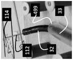
图12a-h绘示了根据本发明的教示所构造的原型的基准测试(bench-testing)。Figures 12a-h illustrate bench-testing of a prototype constructed according to the teachings of the present invention.
具体实施方式Detailed ways
本发明是一种可用于控制标准结肠镜的一结肠镜控制系统。具体而言,本发明可用于远程控制一标准结肠镜,使外科医生能够通过下消化道准确地操纵结肠镜,并操作通过内窥镜的工作通道定位的“小型工具”。The present invention is a colonoscope control system that can be used to control standard colonoscopes. Specifically, the present invention can be used to remotely control a standard colonoscope, allowing the surgeon to precisely maneuver the colonoscope through the lower GI tract and manipulate "miniature tools" positioned through the endoscope's working channel.
参考附图和所附描述,可以更好地理解本发明的原理和操作。The principles and operation of the present invention may be better understood with reference to the drawings and accompanying descriptions.
在详细解释本发明的至少一个实施例之前,应理解的是,本发明的应用不限于以下描述中阐述的或通过实施例举例说明的细节。本发明能够具有其他实施例或能够以各种方式实践或执行。此外,应当理解的是,在此使用的措辞和术语是为了描述的目的,而不应被视为限制性的。Before at least one embodiment of the invention is explained in detail, it is to be understood that the invention is not limited in application to the details set forth in the following description or exemplified by the examples. The invention is capable of other embodiments or of being practiced or carried out in various ways. Also, it is to be understood that the phraseology and terminology used herein are for the purpose of description and should not be regarded as limiting.
通过下消化道的曲折解剖(torturous anatomy)操作标准结肠镜需要技巧和经验。结肠镜检查最严重的并发症之一是结肠内窥镜穿孔,据报道其发生率为0.03%至0.7%。尽管结肠镜下穿孔(colonoscopic perforation,CP)是一种罕见的并发症,但它可与高死亡率和发病率有关。Manipulating a standard colonoscope through the tortuous anatomy of the lower GI tract requires skill and experience. One of the most serious complications of colonoscopy is colonoscopic perforation, which has been reported to occur in 0.03% to 0.7%. Although colonoscopic perforation (CP) is a rare complication, it can be associated with high mortality and morbidity.
在将本发明付诸实践的同时,本发明人设计了一种结肠镜控制系统,所述控制系统能够准确和直观地控制结肠镜在下消化道内的操作。如本文进一步描述的,本控制系统可以改装到现有的标准结肠镜并且能够在对轴前进和/或偏转的电动控制和手动控制之间进行切换。While putting the present invention into practice, the present inventors designed a colonoscope control system capable of accurately and intuitively controlling the operation of the colonoscope in the lower digestive tract. As described further herein, the present control system can be retrofitted to existing standard colonoscopes and is capable of switching between motorized and manual control of shaft advancement and/or deflection.
因此,根据本发明的一个方面,提供了一种控制系统,用于具有可通过两个可旋转旋钮偏转的轴的结肠镜。Therefore, according to one aspect of the present invention, there is provided a control system for a colonoscope having a shaft deflectable by two rotatable knobs.
本发明的控制系统包括安装在结肠镜的一外壳外部的一第一驱动单元。所述第一驱动单元包括一第一驱动机构,用于接合结肠镜的两个可旋转旋钮或包括替代两个可旋转旋钮的齿轮的适配器。所述齿轮安装在两个可旋转旋钮的轴上。The control system of the present invention includes a first drive unit installed outside a housing of the colonoscope. The first drive unit comprises a first drive mechanism for engaging the two rotatable knobs of the colonoscope or an adapter comprising gears instead of the two rotatable knobs. Said gears are mounted on shafts of two rotatable knobs.
控制系统还包括一第二驱动单元,所述第二驱动单元可通过(例如滚轮)附接到内窥镜的所述轴。所述第二驱动单元能够使所述轴向前和向后线性平移,并通过下消化道操作所述轴前进。The control system also includes a second drive unit attachable to the shaft of the endoscope by eg rollers. The second drive unit is capable of linearly translating the shaft forward and backward and manipulating the advancement of the shaft through the lower alimentary canal.
所述控制系统还包括一用户界面,其包括一第一界面,安装在枢轴支撑件(例如,万向节”gimbaled”)上,且可与用户的手掌接合。这样的界面可用于控制所述第一驱动机构来操作所述轴的上/下和左/右偏转。The control system also includes a user interface including a first interface mounted on a pivot support (eg, a gimbaled "gimbaled") and engageable with a user's palm. Such an interface may be used to control the first drive mechanism to operate up/down and left/right deflection of the shaft.
所述用户界面还可以包括一第二界面,用于控制所述第二驱动机构。所述第二界面可以包括用于使所述轴向前和向后线性平移的一滑块界面。The user interface may also include a second interface for controlling the second drive mechanism. The second interface may comprise a slider interface for linearly translating the shaft forward and backward.
所述用户界面还可以包括一第三界面,枢转地附接到所述第一界面。此界面可由一只手的一根或多根手指操作(例如,可通过所述手的拇指和食指同时操作的垫),并用于控制内窥镜轴夹持机构的线性轴前后运动。The user interface may also include a third interface pivotally attached to the first interface. This interface is operable by one or more fingers of a hand (eg, a pad operable simultaneously by the thumb and forefinger of the hand) and is used to control the forward and backward motion of the linear shaft of the endoscope shaft clamping mechanism.
所述用户界面还可包括一第四界面,其包括用于向前和向后线性平移“小型工具”轴的一滑块按钮。所述用户界面还可包括一第五界面,其可由一只手的一根或多根手指操作(例如,可通过拇指和食指同时操作的垫),用于致动通过结肠镜的工作通道定位的工具(例如,抓握器、套索)。The user interface may also include a fourth interface including a slider button for linearly translating the "small tool" axis forward and backward. The user interface may also include a fifth interface, operable by one or more fingers of a hand (e.g., a pad operable simultaneously by the thumb and forefinger) for actuating positioning through the working channel of the colonoscope. tools (e.g., gripper, lasso).
本发明的控制系统的典型布局包括连接到结肠镜控制旋钮(或通过齿轮适配器连接到所述轴)的第一驱动单元、连接到所述轴(例如通过滚轮)的第二驱动单元、以及远离结肠镜并通过有线或无线连接到驱动单元的一用户界面。所述用户界面可以放置在靠近结肠镜和患者的手术室内或手术室外(例如远程医疗),在这种情况下,患者和结肠镜可以通过远程摄像头进行可视化。A typical layout of the control system of the present invention includes a first drive unit connected to the colonoscope control knob (or to the shaft via a gear adapter), a second drive unit connected to the shaft (for example via a roller), and The colonoscope is connected to a user interface of the drive unit by wire or wirelessly. The user interface can be placed close to the colonoscope and patient in the operating room or outside the operating room (eg telemedicine), in which case the patient and colonoscope can be visualized via a remote camera.
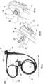
现参考附图,图1和图2说明了本系统的典型手术室设置(图1)和推车布局(图2),本文称为系统10。外科医生14可以使用监视器12来监视程序。如图1所示,所述系统10使用推车20定位在患者700附近。系统10的模块以最佳布局放置在不同的关节式搁板(articulated shelves)22上(下面参考图10-11进一步描述)。外科医生通过用户界面400和401操作结肠镜24。Referring now to the drawings, FIGS. 1 and 2 illustrate a typical operating room setup ( FIG. 1 ) and cart layout ( FIG. 2 ) for the present system, referred to herein as
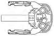
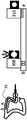
图3a-c示出了现成的结肠镜24(Pentax EC-3831L柔性视频结肠镜内窥镜),其主体26配有手动旋钮28和30。外科医生14可通过将旋钮28和30旋转到期望的方向来使轴33的远侧末端32偏转。带有附接适配器36的照相机电缆和光源34也连接到结肠镜24的主体26。Figures 3a-c show an off-the-shelf colonoscope 24 (Pentax EC-3831L Flexible Video Colonoscope Endoscope) with a
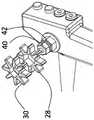
图3b示出了取代手动旋钮28和30的适配器40和42。所述适配器40和42具有设计成与轴44和46的端部接合的锁孔图案,其用于将旋钮输入机械地传输到所述结肠镜24的关节机构。适配器40具有圆形底座48,且适配器42具有圆形底座50。圆形底座48和50用作手动旋钮28和30或在其位置改装的机械齿轮的止动器。图3b还示出了结肠镜24的阀门按钮52和54,它们提供了用于(分别)抽吸和空气/水(分别)通过通道51和53的界面。FIG. 3 b shows
图3c示出了连接到轴44和46的适配器40和42(锁孔防止适配器40和42滑动)。Figure 3c shows the
图3d-f示出了本发明的一个实施例,其中手动旋钮28连接到适配器42并且手动旋钮30连接到适配器40。这种耦合仍然使结肠镜24能够通过旋钮手动操作,并有利于结肠镜24的手动和电动操作之间的快速切换。Figures 3d-f show an embodiment of the invention wherein the
图3g-i示出了齿轮60与适配器40的连接,及齿轮62与适配器42连接。在这种连接之后,结肠镜24可与驱动单元66装配,用于通过齿轮60和62致动关节机构。结肠镜24的附加功能(各种阀门和按钮)也可以连接到其他驱动/控制机构,从而将结肠镜24从手动操作切换为完全电动操作。Figures 3g-i show the connection of the
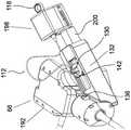
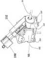
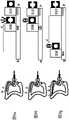
图4a-k示出了所述驱动单元66的组件。所述驱动单元66附接到结肠镜24的主体26的外表面。驱动单元66的电机连接到结肠镜24的旋钮40和42(或通过齿轮连接到所述轴),使得任何标准手动结肠镜能够转换成电动(例如机器人)结肠镜。4a-k show the components of the
图4a示出了电机68和69与安装在结肠镜24上的齿轮60和62的耦合。驱动单元66的外壳70通过支架72固定到结肠镜主体26。沿着底盘70的垂直板78附接的电机68和69通过蜗轮74和76连接到齿轮60和62。电位器80和82也连接到垂直板78并通过齿轮61和63连接到蜗轮74和76。电机控制器75通过支架72固定结肠镜主体26。FIG. 4 a shows the coupling of
图4c-e示出了驱动单元,其在本文中被称为驱动单元132,其可用于控制“小型工具”通过结肠镜24的工作通道的前进和致动。4c-e illustrate a drive unit, referred to herein as
结肠镜检查通常需要在手术过程中对组织进行取样或处理。这种取样或处理可以使用“小型工具”进行,其插入通过结肠镜24的工作通道,并且定位在结肠镜轴33的远端外,使得其末端执行器接近所需组织。外科医生可接着使用末端执行器(例如,抓握器或套索或任何其他工具),以便处理或取回组织样本。Colonoscopy often requires sampling or processing of tissue during the procedure. Such sampling or processing may be performed using a "small tool" that is inserted through the working channel of the
图4e中示出了典型的小型工具(本文称为工具110)。工具110包括细的柔性轴112(通常直径为1.2-3.1mm,长度为60-210cm)。工具110包括位于轴112远端的末端执行器114。末端执行器114通常是手动操作的,使用固定的手柄118和滑动按钮127。将滑块按钮127推过手柄118朝向轴112的远端打开工具110的钳口,反之亦然。A typical small tool (referred to herein as tool 110) is shown in Figure 4e.
图4c示出了连接到外壳70的适配器130。适配器130利用穿过孔134的螺钉(未示出)将工具110推/拉驱动单元132连接到外壳70。主体26中的端口136提供通向结肠镜24工作通道的通道。FIG. 4c shows the
图4d示出了工具110的驱动单元132的基本部件。为了将轴112平移出工作通道并将末端执行器114准确定位在期望的解剖标志处,将轴112插入适配器130的凹槽142中并通过旋钮144固定。FIG. 4d shows the essential components of the
适配器130连接到具有50mm典型移动范围的滑块148。滑块148通过螺杆机构来驱动,螺杆机构包括螺杆156、电机(未示出)和联接到齿轮160的齿轮158。The
为了使用工具110,外科医生滑动轴112通过结肠镜24的工作通道,直到末端执行器114在监视器12中可见。外科医生接着如上所述将轴112固定到适配器130。To use
图4f示出了通过适配器130连接到外壳70的驱动单元132,凹槽142与端口136的中心对齐。FIG. 4 f shows drive
图4g示出了一电动机构170,用于电动启动吸入阀52和空气/水阀54。Figure 4g shows an
外壳70包括用作螺线管182和184的外壳的突起180,螺线管182和184(分别)激活阀52和54。外科医生通过开关控制每个阀的状态,如下面参照图7b进一步描述的。
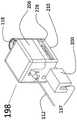
图4h示出了一种配置,其中驱动单元132和驱动单元66共享一个公共外壳192的配置。轨条194形成外壳192的一部分并且用作工具110的打开/关闭模块198的连接器(图4i)。模块198可通过连接器200可释放地连接到驱动单元132。连接器137是底盘210的一部分。为了启动工具110的打开/关闭动作,将把手118插入模块198,轴112指向驱动单元132。工具110的按钮127被夹入模块198的打开/关闭机构,且盖206在底盘210上滑动以关闭模块198。FIG. 4h shows a configuration in which drive
图4j示出了模块198的打开/关闭机构。把手主体118夹入外壳218和外壳222中,滑动按钮127夹入旋转杆224的臂中。杆224连接到伺服电机226,伺服电机226又通过滑块228连接到底盘210。伺服电机226的滑块228用于优化杆224的旋转点,从而能够使用不同类型、长度和形状的不同小型工具。FIG. 4j shows the opening/closing mechanism of
当杆224向前转动时,把手127被向前推动。把手127通过推/拉线连接到末端执行器114。通过推动小型工具110的推/拉线,末端执行器114的钳口机构使钳口打开。滑动按钮127的向后移动将导致末端执行器114的钳口闭合。When the
图4k示出了驱动单元66、132和模块198的典型配置。驱动单元132连接到驱动单元66。启动小型工具远端执行器114的打开关闭的模块198连接到驱动单元132。A typical configuration of
图4l示出了组装在外壳217中的驱动单元66和132以及模块198。如下文进一步描述的,真空垫237用于将外壳217固定到任何平坦表面。FIG. 41 shows drive
图5a-c示出了一驱动单元300,用于前进/缩回内窥镜24的柔性轴33。5 a - c show a
图5a是驱动单元300的透视图。驱动单元300包括电动线性机构302和2个抓握致动器308和310,所述电动线性机构302线性驱动具有100mm线性行程范围的线性滑块304。FIG. 5 a is a perspective view of the
滚轮312和314位于臂315的侧面,凹槽316位于它们之间。滚轮和凹槽装置将柔性轴33引导到抓握致动器310中。盖子344通常通过真空垫330连接到板22。板22通过臂402连接到推车20。
盖子344上的按钮340控制两个抓握致动器(308和310)。为了将柔性轴33安装在驱动单元300中,外科医生点击按钮340以打开抓握致动器308和310,然后可将柔性轴33放置在抓握致动器308和310的夹爪之间,并通过再次单击按钮340将柔性轴33锁定在抓握致动器308和310内。
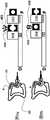
图5b示出了驱动单元300的组件。主体350包括基于螺钉(screw-based)的线性驱动机构,其驱动在主体350上的滑块304(从指示近端位置的点P到指示远端位置的点D)。抓握致动器308附接到滑块304。抓握致动器308与滑块304一起线性行进,且在下文中被称为“移动抓握致动器”。抓握致动器310附接到主体350的近端P且在下文中被称为“固定抓握致动器”。抓握致动器308和310都具有被设计成与柔性轴33最佳接触的盖368,从而能够使用不同类型、长度涂层材料和直径的不同内窥镜类型。FIG. 5 b shows the components of the
图5c示出了抓握致动器308和310。主体360包括电机361和基于螺杆的线性机构。所述线性机构沿着轨道366驱动臂362和臂364。FIG. 5c shows
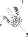
图6a-c和7a-b示出了驱动单元300的用户界面(下文中的界面400)。Figures 6a-c and 7a-b show the user interface of the drive unit 300 (hereinafter interface 400).
为了通过驱动单元300控制轴33推/拉,外科医生抓住界面400的主体404的掌托402(图7a),食指和拇指接合手指界面405的指垫406和408(图6b-c)。指垫406和408可在图6b所示的打开状态和图6c所示的闭合状态之间被致动。To control
指垫406和408控制抓握致动器308和310。当指垫406和408打开时,如图6b所示,抓握致动器308的钳口是打开的。当指垫406和408闭合时,在图6c中,抓紧致动器308的钳口闭合并向柔性轴33施加摩擦力。此摩擦力使外科医生能够控制柔性轴33的推/拉。
控制界面400还控制柔性轴33的远侧关节32以及抽吸阀和空气/水阀。为了理解由界面400控制的远侧关节32的机制和结构,现在参考图7b。The
图7b示出了允许外科医生(分别)通过按钮154和156同时控制柔性轴33的关节、吸入阀和空气/水功能的阀52,54的结构和部件。Figure 7b shows the structure and components of the
为了控制关节的左/右上/下运动,外科医生将界面主体404旋转到期望的侧面和高度。电位器170和172测量主体404的方向(如图7b所示),且它们的电信号由电控制器75转换为电机68、70的旋转命令。当电机68和69旋转时,蜗轮74和76旋转导致远端关节运动机构的轴旋转。在旋转的同时,蜗轮74和76也使齿轮61和63旋转。齿轮61、63连接到旋转电位器80、81。To control the left/right up/down motion of the joint, the surgeon rotates the
来自电位器80、81的信号被发送到控制器75并与来自主体404的定向电位器170、172的信号进行比较,从而使控制器75将将下一个旋转命令发送到电机,直到测量到来自电机的电位器80、81和控制界面主体404的电位器170、172相等,或在允许的差异范围内。The signal from the
可以100Hz或更高的频率对上述测量和运动周期进行采样,以确保关节机构的快速反应而没有任何延迟。The above-mentioned measurements and motion cycles can be sampled at a frequency of 100 Hz or higher to ensure a fast reaction of the joint mechanism without any delay.
如图7a所示,主体404连接到外壳412。外壳412可以在外壳418的近端414(p)和远端416(d)之间线性滑动。线性电位器定位在外壳418中,当外科医生沿着滑块外壳420滑动外壳412时,线性电位器415滑块测量界面主体404的位置和方向。界面400的主体404的组合测量值和指垫406和408的状态使外科医生能够控制驱动单元300,这将在图9a-g中详细描述。The
为了通过推/拉模块132控制“小型工具”轴,外科医生握住界面401的主体407的扁平部分(图7c),并且沿着滑动器壳体429滑动壳体419,电位计滑动器测量界面主体407的位置。来自电位计的位置信号被发送到控制器75,控制器75将信号转换成运动命令到模块132,模块132驱动“小型工具”轴112。在控制轴112的线性运动的同时,外科医生可以同时通过控制手指界面405的垫406和408的打开-关闭状态来控制末端执行器114的激活。控制器75测量指垫406和408的状态,并相应地启动打开关闭模块198,使外科医生能够控制“小型工具”轴112远端的位置,同时控制末端执行器114的启动。To control the "small tool" axis via the push/
图8a-h说明了附加的电动模块,使柔性轴能够沿其长轴进行滚动运动。外科医生可以使用滚动运动来更好地定位柔性轴的远端,同时它在消化道中前进。Figure 8a–h illustrate the addition of motorized modules that enable rolling motion of the flexible shaft along its long axis. The surgeon can use the rolling motion to better position the distal end of the flexible shaft while it advances in the digestive tract.
为了旋转内窥镜柔性轴33,模块500通过连接器510连接到推/拉模块300,柔性轴的中心在弧508的中心(定位点C)。弧508铰链连接到框架502。弧508包括在其远端与蜗轮506啮合的齿轮507。电机504转动蜗轮。当电机504被界面400(参照图8e-h描述)激活时,推/拉模块300围绕点C旋转,如图8c-d所示。In order to rotate the endoscope
图8e-h示出了附加旋转框架模块600。模块600包含在具有真空支脚604的固定底座606中。框架608通过铰链603和605铰接到固定框架606。旋转传感器602连接到铰链605并连续测量角度α。为了控制结肠镜轴围绕其中心的旋转,界面400通过真空垫150附接到旋转框架608的表面607。为了旋转结肠镜轴,外科医生倾斜界面从而类似地旋转框架608。旋转传感器测量值用作电机504的输入,电机504使模块300围绕中心点C旋转。图8g-h举例说明了框架608的倾斜位置。这种界面配置使外科医生能够同时且直观地控制柔性轴33的推/拉运动、远端32的关节(左/右、上/下)和柔性轴33的滚动角(roll angle)。Figures 8e-h show additional
抓握致动器308有几种操作状态:The
(i)闭合和静态;(i) closed and static;
(ii)打开和静态;(ii) open and static;
(iii)通过远端运动(朝向患者身体)闭合;(iii) closed by distal movement (towards the patient's body);
(iv)通过近端运动(离开患者身体)闭合;(iv) closure by proximal movement (away from the patient's body);
(v)打开远端运动;及(v) open distal movement; and
(vi)打开和近端运动。(vi) Opening and proximal movement.
图9a-g示意性地示出了一系列的界面400输入和驱动单元300的相应机械输出。Figures 9a-g schematically illustrate a series of
图9a示意性地示出了柔性轴33,其远端位于患者下消化道中的A点。指垫406和408处于打开状态且抓握致动器308同样打开。抓握致动器310关闭以消除结肠镜轴33的任何不期望的运动。Figure 9a schematically shows a
图9b示出了处于闭合状态的指垫406和408,抓握致动器308同样闭合并抓握柔性轴33。然而,抓握致动器310打开,轴33不移动,因为外科医生没有移动掌托404。FIG. 9 b shows the
当外科医生在指垫406和408处于闭合状态时将界面主体404向远侧朝向点D移动时,抓握致动器308向着D点移动。由于抓握致动器310是打开的,因此柔性轴33在患者的消化道中从A点平移到B点。When the surgeon moves
为了将轴33从B点推进到C点,外科医生打开指垫406和408,从而关闭抓握致动器310,并打开抓握致动器308(图9d)。外科医生接着将界面主体404滑动到点P,然后外科医生关闭指垫406和408,从而关闭抓握致动器308并打开抓握致动器310。在指垫406和408闭合的情况下向远侧移动界面主体404(图12g)导致柔性轴33移动到点C。此事件顺序类似于结肠镜轴的手动挤压和拖动,并使外科医生能够以模仿手动程序的直观方式向前和向后拖动柔性轴33,而无需掌握新的技能和手术技术。应该注意的是,在例如需要触觉反馈(hapticfeedback)的情况下,外科医生在任何时候都可以选择手动控制柔性轴33的运动。To advance
掌托主体404的直线运动与柔性轴33远端的行程之间的比例可以在手术过程中的任何时候由外科医生根据自己的需要进行选择。典型的比例可以在1:0.5到1:4之间。The ratio between the linear movement of the
本发明的系统10可用于以下的下消化道程序(例如结肠镜检查)。The
图10说明了系统10的典型设置,可用于下消化道程序。Figure 10 illustrates a typical setup of
患者700侧躺着,他/她背对着系统10。柔性轴33的远端通过肛孔插入患者的下消化道。驱动单元300被移动到期望位置且柔性轴33被安装到驱动单元300中并且被两个抓握致动器(308和310)抓取。驱动单元66、132和198具有共同的盖192,组装到底座217中,位于搁板22上,由臂422和423移动到相对于驱动单元300的最佳位置。柔性轴33的松弛由前轮312、314处理。结肠镜控制界面400和小型工具控制界面401位于不同的板上,以方便外科医生。The
为了进行操作,外科医生握住界面400和401并移动柔性轴33通过下消化道。外科医生可以使用界面400将柔性轴的远端定位在相对于患者解剖结构的最佳位置和关节定向,同时使用界面401控制小型工具末端执行器的位置和激活。在任何时候,外科医生都可以通过按下位于界面主体404前面的按钮154和156(如图7b所示)来操作抽吸/冲洗系统和空气系统。此外,在任何时候(例如,在需要触觉反馈的情况下),外科医生可以选择将内窥镜和小型工具与电动模块断开,以便手动控制柔性轴33和/或小型工具的运动。To operate, the surgeon grasps the
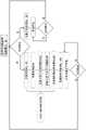
图11是描述结肠镜的工作模式选择的框图,所述结肠镜装配有本系统并且可选地由本系统控制。Figure 11 is a block diagram depicting the selection of operating modes of a colonoscope equipped with and optionally controlled by the present system.
当外科医生为手术准备结肠镜时,他/她可以在开始时选择首选的工作模式。如果外科医生更喜欢从手动模式开始(图的左分支),他/她将手动旋钮安装在适配器上。如果外科医生更喜欢从电动模式开始(图的右分支),他/她将齿轮安装在适配器上,然后安装上文所述的电动驱动单元。When the surgeon prepares the colonoscope for surgery, he or she can initially select the preferred working mode. If the surgeon prefers to start in manual mode (left branch of the diagram), he/she mounts the manual knob on the adapter. If the surgeon prefers to start in electric mode (right branch of the diagram), he/she installs the gear on the adapter and then installs the electric drive unit as described above.
在手术的任何阶段,外科医生都可以在电动和手动模式之间交替。例如,如果外科医生在手动模式下工作时希望切换到电动模式,他/她只需移除手动旋钮并安装齿轮、适配器和驱动单元。在外科医生想要切换到手动模式的情况下,可以反转此过程。At any stage of the procedure, the surgeon can alternate between electric and manual modes. For example, if a surgeon wishes to switch to electric mode while working in manual mode, he or she simply removes the manual knob and installs the gears, adapter and drive unit. In the event the surgeon wants to switch to manual mode, this process can be reversed.
如本文所使用,术语“约”是指10%。As used herein, the term "about" means 10%.
本发明的另外的目的、优点和新颖的特征对于本领域的普通技术人员在检查以下实施例后将变得显而易见,这些实施例不旨在限制。Additional objects, advantages and novel features of the present invention will become apparent to those of ordinary skill in the art upon examination of the following examples, which are not intended to be limiting.
示例example
现在参考以下示例,其与以上描述一起以非限制性方式说明本发明。Reference is now made to the following examples, which together with the foregoing description illustrate the invention in a non-limiting manner.
对原型系统进行基准测试Benchmark the prototype system
构建了本系统的原型,并对其功能进行了基准测试。A prototype of the system was constructed and its functionality was benchmarked.
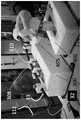
图12a-b展示了柔性轴界面400,操作者的手抓住界面400的主体404。柔性轴33的远侧部分32根据主体404的方位铰接——在图12a右侧及在图12b上方。Figures 12a-b illustrate the
这些图中还展示了推拉模块300。手指的垫406、408处于打开位置(且抓握器308打开并且固定抓握器310关闭)。Also shown in these figures is a push-
消化道模拟器(标示为499)用于测试柔性轴(图12c-g)的操纵。图12c展示了柔性轴33与远端部分32在消化道模拟器中的运动。图12d展示了“小型工具”轴112的远端和从轴33远端部分32的远端传送的小型工具110的抓握器114。图12e展示了本系统的关节控制能力,示出了远端部分32被绞接(articulated)并引导出消化道模拟器。图12f展示了在柔性轴33引导出消化道模拟器时,控制小型工具110(轴112和末端执行器114)的能力。图12g展示了对柔性轴33的远侧关节32的控制以及小型工具110的伴随控制。图12h展示了在抓紧器308和310处于打开位置时对柔性轴33的手动控制。A gut simulator (designated 499) was used to test the manipulation of the flexible shaft (Fig. 12c-g). Figure 12c shows the movement of the
应当理解的是,为了清楚起见,在单独实施例的上下文中描述的本发明的某些特征也可以在单个实施例中组合提供。相反地,为了简洁起见,在单个实施例的上下文中描述的本发明的各种特征也可以单独提供或以任何合适的子组合提供。It is to be appreciated that certain features of the invention, which are, for clarity, described in the context of separate embodiments, may also be provided in combination in a single embodiment. Conversely, various features of the invention which are, for brevity, described in the context of a single embodiment, may also be provided separately or in any suitable subcombination.
尽管已经结合其特定实施例描述了本发明,但显然许多替代、修改和变化对于本领域技术人员来说将是显而易见的。因此,旨在涵盖落入所附权利要求的精神和广泛范围内的所有这些替代、修改和变化。本说明书中提及的所有出版物、专利和专利申请在此通过引用的方式整体并入本说明书中,其程度如同每个单独的出版物、专利或专利申请被具体地和单独地指示通过引用并入本文一样。此外,本申请中任何参考文献的引用或标识不应被解释为承认此类参考文献可用作本发明的现有技术。在使用章节标题的范围内,它们不应被解释为必然限制。此外,本申请的任何优先权文件在此全部并入本文。Although the invention has been described in conjunction with specific embodiments thereof, it is evident that many alternatives, modifications and variations will be apparent to those skilled in the art. It is therefore intended to embrace all such alternatives, modifications and changes that fall within the spirit and broad scope of the appended claims. All publications, patents, and patent applications mentioned in this specification are hereby incorporated by reference in their entirety into this specification to the same extent as if each individual publication, patent, or patent application was specifically and individually indicated to be incorporated by reference. Incorporated into this article as well. In addition, citation or identification of any reference in this application shall not be construed as an admission that such reference is available as prior art to the present invention. To the extent section headings are used, they should not be construed as necessarily limiting. In addition, any priority documents of this application are hereby incorporated in their entirety.
Claims (8)
Applications Claiming Priority (3)
| Application Number | Priority Date | Filing Date | Title |
|---|---|---|---|
| US202062981569P | 2020-02-26 | 2020-02-26 | |
| US62/981,569 | 2020-02-26 | ||
| PCT/IL2021/050211WO2021171292A1 (en) | 2020-02-26 | 2021-02-24 | Control system for a colonoscope |
Publications (1)
| Publication Number | Publication Date |
|---|---|
| CN115334952Atrue CN115334952A (en) | 2022-11-11 |
Family
ID=77490773
Family Applications (1)
| Application Number | Title | Priority Date | Filing Date |
|---|---|---|---|
| CN202180022587.4APendingCN115334952A (en) | 2020-02-26 | 2021-02-24 | Control system for colonoscope |
Country Status (5)
| Country | Link |
|---|---|
| US (1) | US12433474B2 (en) |
| EP (1) | EP4110160A4 (en) |
| JP (1) | JP2023515085A (en) |
| CN (1) | CN115334952A (en) |
| WO (1) | WO2021171292A1 (en) |
Families Citing this family (1)
| Publication number | Priority date | Publication date | Assignee | Title |
|---|---|---|---|---|
| CN115334952A (en) | 2020-02-26 | 2022-11-11 | 人类拓展有限公司 | Control system for colonoscope |
Citations (1)
| Publication number | Priority date | Publication date | Assignee | Title |
|---|---|---|---|---|
| CN107847105A (en)* | 2015-08-11 | 2018-03-27 | 人类扩展有限公司 | Control unit for soft endoscope |
Family Cites Families (11)
| Publication number | Priority date | Publication date | Assignee | Title |
|---|---|---|---|---|
| JPH042318Y2 (en) | 1985-01-28 | 1992-01-27 | ||
| JPH042318A (en)* | 1990-04-20 | 1992-01-07 | Olympus Optical Co Ltd | Endoscope |
| US5159446A (en) | 1991-06-21 | 1992-10-27 | Olympus Optical Co., Ltd. | Electronic endoscope system provided with a separate camera controlling unit and motor controlling unit |
| JPH1132977A (en)* | 1997-07-17 | 1999-02-09 | Olympus Optical Co Ltd | Endoscope system |
| MXPA05013759A (en) | 2003-06-16 | 2006-06-27 | Ethicon Endo Surgery Inc | Surgical system with a stapling instrument and a retractor. |
| US7789825B2 (en) | 2003-09-29 | 2010-09-07 | Ethicon Endo-Surgery, Inc. | Handle for endoscopic device |
| WO2011119521A1 (en)* | 2010-03-22 | 2011-09-29 | Tufts Medical Center, Inc. | Fiber optic intubating device |
| CN104027061B (en)* | 2012-04-24 | 2016-07-06 | 王东 | Soft endoscope system based on automatically controlled driving instruments |
| CN106491211B (en) | 2016-09-30 | 2019-02-12 | 江苏风和医疗器材股份有限公司 | A kind of stapler percussion force checking device |
| US10709316B2 (en)* | 2017-06-06 | 2020-07-14 | Eladio A. Vargas | Method and apparatus for a rotating sleeve for endoscopic propulsion with mitigation of colonoscopic perforation |
| CN115334952A (en) | 2020-02-26 | 2022-11-11 | 人类拓展有限公司 | Control system for colonoscope |
- 2021
- 2021-02-24CNCN202180022587.4Apatent/CN115334952A/enactivePending
- 2021-02-24WOPCT/IL2021/050211patent/WO2021171292A1/ennot_activeCeased
- 2021-02-24JPJP2022549937Apatent/JP2023515085A/enactivePending
- 2021-02-24USUS17/801,814patent/US12433474B2/enactiveActive
- 2021-02-24EPEP21761572.3Apatent/EP4110160A4/enactivePending
Patent Citations (2)
| Publication number | Priority date | Publication date | Assignee | Title |
|---|---|---|---|---|
| CN107847105A (en)* | 2015-08-11 | 2018-03-27 | 人类扩展有限公司 | Control unit for soft endoscope |
| US20180098687A1 (en)* | 2015-08-11 | 2018-04-12 | Human Xtensions Ltd. | Control unit for a flexible endoscope |
Also Published As
| Publication number | Publication date |
|---|---|
| EP4110160A1 (en) | 2023-01-04 |
| WO2021171292A1 (en) | 2021-09-02 |
| EP4110160A4 (en) | 2024-03-27 |
| US20230104573A1 (en) | 2023-04-06 |
| US12433474B2 (en) | 2025-10-07 |
| JP2023515085A (en) | 2023-04-12 |
Similar Documents
| Publication | Publication Date | Title |
|---|---|---|
| US20210212710A1 (en) | Control unit for a medical device | |
| US10835108B2 (en) | Control unit for a flexible endoscope | |
| US7871371B2 (en) | Endoscope system equipped with manipulating unit for commanding medical therapy to endoscope and medical instrument attached thereto | |
| US20170312043A1 (en) | Operation input device and medical manipulator system | |
| EP2116175B1 (en) | Medical system | |
| US20030208187A1 (en) | Apparatus for positioning a medical instrument | |
| KR20190113988A (en) | Controller for Surgical Instruments | |
| JP2010511440A5 (en) | ||
| CN105392412B (en) | Surgeon controlled endoscopic device and method | |
| CN108348226A (en) | The control assembly of Medical Devices and relevant application method | |
| US12433474B2 (en) | Control system for a colonoscope | |
| JP6979025B2 (en) | Surgical system | |
| WO2025085415A1 (en) | Systems and methods for controlling a sequential workflow | |
| WO2025085438A1 (en) | Systems and methods for actuating an instrument system | |
| HK40008022A (en) | Control unit for a medical device | |
| HK40008022B (en) | Control unit for a medical device | |
| CN115120352A (en) | Endoscopic surgical equipment | |
| HK1253926B (en) | Control unit attachable to an endoscope having a shaft deflectable via two rotatable knobs to allow one-handed operation of the knobs | |
| HK1253926A1 (en) | Control unit attachable to an endoscope having a shaft deflectable via two rotatable knobs to allow one-handed operation of the knobs |
Legal Events
| Date | Code | Title | Description |
|---|---|---|---|
| PB01 | Publication | ||
| PB01 | Publication | ||
| SE01 | Entry into force of request for substantive examination | ||
| SE01 | Entry into force of request for substantive examination | ||
| TA01 | Transfer of patent application right | ||
| TA01 | Transfer of patent application right | Effective date of registration:20250829 Address after:Israel Applicant after:Herman Tek Surgical Co., Ltd. Country or region after:Israel Address before:Israel Neitanyashi Applicant before:HUMAN EXTENSIONS LTD. Country or region before:Israel |