CN115331635A - Display device and display method - Google Patents
Display device and display methodDownload PDFInfo
- Publication number
- CN115331635A CN115331635ACN202110512024.5ACN202110512024ACN115331635ACN 115331635 ACN115331635 ACN 115331635ACN 202110512024 ACN202110512024 ACN 202110512024ACN 115331635 ACN115331635 ACN 115331635A
- Authority
- CN
- China
- Prior art keywords
- backlight
- pulse signal
- backlight module
- blocks
- deblurring
- Prior art date
- Legal status (The legal status is an assumption and is not a legal conclusion. Google has not performed a legal analysis and makes no representation as to the accuracy of the status listed.)
- Granted
Links
Images
Classifications
- G—PHYSICS
- G09—EDUCATION; CRYPTOGRAPHY; DISPLAY; ADVERTISING; SEALS
- G09G—ARRANGEMENTS OR CIRCUITS FOR CONTROL OF INDICATING DEVICES USING STATIC MEANS TO PRESENT VARIABLE INFORMATION
- G09G3/00—Control arrangements or circuits, of interest only in connection with visual indicators other than cathode-ray tubes
- G09G3/20—Control arrangements or circuits, of interest only in connection with visual indicators other than cathode-ray tubes for presentation of an assembly of a number of characters, e.g. a page, by composing the assembly by combination of individual elements arranged in a matrix no fixed position being assigned to or needed to be assigned to the individual characters or partial characters
- G09G3/34—Control arrangements or circuits, of interest only in connection with visual indicators other than cathode-ray tubes for presentation of an assembly of a number of characters, e.g. a page, by composing the assembly by combination of individual elements arranged in a matrix no fixed position being assigned to or needed to be assigned to the individual characters or partial characters by control of light from an independent source
- G09G3/3406—Control of illumination source
- G09G3/342—Control of illumination source using several illumination sources separately controlled corresponding to different display panel areas, e.g. along one dimension such as lines
Landscapes
- Engineering & Computer Science (AREA)
- Physics & Mathematics (AREA)
- Computer Hardware Design (AREA)
- General Physics & Mathematics (AREA)
- Theoretical Computer Science (AREA)
- Liquid Crystal Display Device Control (AREA)
- Control Of Indicators Other Than Cathode Ray Tubes (AREA)
Abstract
Description
Translated fromChinese技术领域technical field
本公开是有关于一种显示设备,特别是一种能够支持区域调光及减少动态模糊的显示设备。The present disclosure relates to a display device, in particular to a display device capable of supporting local dimming and reducing motion blur.
背景技术Background technique
液晶(liquid crystal,LC)显示面板是现今常见的显示面板。液晶显示面板可包含排列成阵列的液晶像素。由于液晶具有特殊的光电特性,因此通过在液晶像素上施加电压,就可以改变液晶的排列方向,从而控制液晶像素的透光率。也就是说,显示设备可根据显示数据调整液晶像素的透光率以及调整背光模块的亮度,以使每个液晶像素呈现出所需的亮度。A liquid crystal (liquid crystal, LC) display panel is a common display panel nowadays. A liquid crystal display panel may include liquid crystal pixels arranged in an array. Because liquid crystals have special photoelectric properties, the alignment direction of liquid crystals can be changed by applying a voltage to the liquid crystal pixels, thereby controlling the light transmittance of the liquid crystal pixels. That is to say, the display device can adjust the light transmittance of the liquid crystal pixels and the brightness of the backlight module according to the display data, so that each liquid crystal pixel can display the required brightness.
由于人眼在追踪画面中的物体运动时,人脑会依据物体移动的速度而预期在物体可能出现的位置上看见物体,然而改变液晶透光率所需的反应时间较长,因此液晶显示面板在呈现动态画面时,常会因为人脑所预期的物体位置与画面中物体位置不同,而产生动态模糊(motion blur)的状况。为了减少动态模糊的问题,现有技术常利用插入黑画面的方式,来避免人眼看到画面中与人脑预期不同的物体位置。此外,为了能够节省液晶显示面板的功耗,现有技术也会对背光模块的发光方式有较为精细的操作。在此情况下,为满足系统的各种需求,液晶显示面板需要在每个帧时间内,对背光模块的驱动电路下达多组指令。再者,为避免呈现画面时出现异常,各组指令的执行时间也必须相互配合,导致驱动电路的操作时序十分复杂,甚至会造成系统的不稳定性。因此如何有效地控制驱动电路及背光模块,已成为本领域有待解决的问题。When the human eye is tracking the movement of the object in the screen, the human brain will expect to see the object at the position where the object may appear according to the moving speed of the object. However, the reaction time required to change the light transmittance of the liquid crystal is long, so the liquid crystal display panel When presenting a dynamic picture, the position of the object expected by the human brain is different from the position of the object in the picture, resulting in motion blur (motion blur). In order to reduce the problem of motion blur, in the prior art, a method of inserting a black frame is often used to prevent human eyes from seeing object positions in the frame that are different from those expected by the human brain. In addition, in order to save the power consumption of the liquid crystal display panel, the prior art also has relatively fine operations on the light emitting mode of the backlight module. In this case, in order to meet various requirements of the system, the liquid crystal display panel needs to issue multiple sets of instructions to the driving circuit of the backlight module within each frame time. Furthermore, in order to avoid abnormality when displaying images, the execution time of each group of instructions must also cooperate with each other, resulting in a very complicated operation sequence of the driving circuit, and even causing system instability. Therefore, how to effectively control the driving circuit and the backlight module has become a problem to be solved in this field.
发明内容Contents of the invention
本公开的一实施例提供一种显示设备,该显示设备包含液晶显示面板、背光模块、控制电路、驱动电路及波形产生电路。液晶显示面板包含多个液晶像素。背光模块用以产生该液晶显示面板所需的背光,该背光模块包含多个背光区块。控制电路用以依据输入显示数据判断在帧周期内,多个背光区块中每一背光区块所对应的背光亮度,并且依据该些背光区块所对应的多个背光亮度产生控制信号。驱动电路用以依据该控制信号在该帧周期内产生多个驱动信号至该背光模块。波形产生电路用以在该帧周期内产生去模糊脉冲信号至该背光模块。其中该背光模块中的多个背光区块是在该去模糊脉冲信号处于高电位时,依据多个驱动信号发光。An embodiment of the present disclosure provides a display device, which includes a liquid crystal display panel, a backlight module, a control circuit, a driving circuit, and a waveform generating circuit. The liquid crystal display panel includes a plurality of liquid crystal pixels. The backlight module is used to generate the backlight required by the liquid crystal display panel, and the backlight module includes a plurality of backlight blocks. The control circuit is used for judging the backlight brightness corresponding to each of the multiple backlight blocks within the frame period according to the input display data, and generating control signals according to the multiple backlight brightnesses corresponding to the backlight blocks. The driving circuit is used for generating a plurality of driving signals to the backlight module within the frame period according to the control signal. The waveform generating circuit is used for generating a blurring pulse signal to the backlight module within the frame period. Wherein the plurality of backlight blocks in the backlight module emit light according to a plurality of driving signals when the deblurring pulse signal is at a high potential.
本公开的另一实施例提供一种显示方法,包含依据输入显示数据判断在帧周期内,背光模块的多个背光区块中每一背光区块所对应的背光亮度,依据多个背光区块所对应的多个背光亮度产生控制信号,利用驱动电路并依据该控制信号在该帧周期内产生多个驱动信号至该背光模块,利用波形产生电路在该帧周期内产生去模糊脉冲信号至该背光模块,在该去模糊脉冲信号处于高电位时,该背光模块依据多个驱动信号产生液晶显示面板所需的背光,及利用该背光模块所产生的背光并通过该液晶显示面板以显示图像。Another embodiment of the present disclosure provides a display method, including judging the backlight brightness corresponding to each backlight block in a plurality of backlight blocks of a backlight module within a frame period according to input display data, and according to a plurality of backlight blocks A plurality of corresponding backlight brightness control signals are generated, a driving circuit is used to generate a plurality of driving signals to the backlight module within the frame period according to the control signal, and a waveform generation circuit is used to generate a deblurring pulse signal to the backlight module within the frame period. A backlight module, when the deblurring pulse signal is at a high potential, the backlight module generates the backlight required by the liquid crystal display panel according to a plurality of driving signals, and uses the backlight generated by the backlight module to display images through the liquid crystal display panel.
本公开的实施例所提供的显示设备及显示方法是利用波形产生电路来产生去模糊脉冲信号,因此可以简化控制电路及驱动电路的操作,从而减少因为控制信号延迟所导致之画面亮度不如预期和/或画面闪烁的异常状况。The display device and display method provided by the embodiments of the present disclosure use the waveform generation circuit to generate the deblurring pulse signal, so the operation of the control circuit and the driving circuit can be simplified, thereby reducing the brightness of the screen caused by the delay of the control signal. /or the abnormal condition that the screen flickers.
附图说明Description of drawings
图1是本公开一实施例的显示设备的示意图。FIG. 1 is a schematic diagram of a display device according to an embodiment of the present disclosure.
图2是操作图1的显示设备的方法流程图。FIG. 2 is a flowchart of a method of operating the display device of FIG. 1 .
图3是在帧周期内,显示设备所产生的信号时序图。FIG. 3 is a timing diagram of signals generated by a display device within a frame period.
图4是在帧周期内,显示设备所产生的另一信号时序图。FIG. 4 is a timing diagram of another signal generated by the display device within a frame period.
具体实施方式Detailed ways
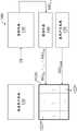
图1是本公开一实施例的显示设备100的示意图。显示设备100包含液晶显示面板110、背光模块120、控制电路130、驱动电路140及波形产生电路150。FIG. 1 is a schematic diagram of a
液晶显示面板110包含多个液晶像素,而背光模块120可产生液晶显示面板110所需的背光。在本实施例中,背光模块120可包含多个背光区块1221至122N,且每一个背光区块1221至122N可以被独立地控制,以进行区域调光。举例来说,当要呈现的图像画面中,左上的图像内容亮度较高,而右下的图像内容亮度较低时,显示设备100便可以使位于左上的背光区块1221发出亮度较高的背光,并使位于右下的背光区块122N发出亮度较低的背光,也就是说,背光模块120可以依据所欲呈现的图像内容,使背光区块1221至122N分别提供对应亮度的背光光源,以提高呈现画面时的对比度和/或减少功耗。The liquid
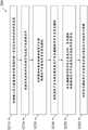
图2是操作显示设备100的方法200的流程图。方法200可包含步骤S210至S260。FIG. 2 is a flowchart of a
S210:依据输入显示数据DI判断在帧周期FP1内每一背光区块1221至122N所对应的背光亮度;S210: Determine the backlight brightness corresponding to each
S220:依据背光区块1221至122N所对应的背光亮度产生控制信号SIGC1;S220: Generate a control signal SIGC1 according to the backlight brightness corresponding to the
S230:利用驱动电路140并依据控制信号SIGC1在帧周期FP1内产生驱动信号SIGD1至SIGDN至背光模块120;S230: Utilize the
S240:利用波形产生电路150在帧周期FP1内产生去模糊脉冲信号SIGMBR至背光模块120;S240: Utilize the waveform generating
S250:在去模糊脉冲信号SIGMBR处于高电位时,背光模块120依据驱动信号SIGD1至SIGDN产生液晶显示面板110所需的背光;以及S250: When the deblurring pulse signal SIGMBR is at a high potential, the
S260:利用背光模块120所产生的背光并通过液晶显示面板110来显示图像。S260: Using the backlight generated by the
控制电路130可在步骤S210中依据输入显示数据DI判断在每一个帧周期内,每一背光区块1221至122N所对应的背光亮度,并可在步骤S220中依据背光区块1221至122N所对应的背光亮度产生控制信号SIGC1。在本实施例中,控制电路130可例如包含缩放器(Scaler)。The
接着在步骤S230中,驱动电路140可依据控制信号SIGC1在每一个帧周期内产生多个驱动信号SIGD1至SIGDN至背光模块120,从而对应地驱动背光模块120中的背光区块1221至122N,达到区域调光的效果。Then in step S230, the
在本实施例中,为减少动态模糊的问题产生,显示设备100会使背光模块120以闪光(strobe light)的方式提供背光。也就是说,在每个帧周期内,背光模块120都只会在特定的时段发光,而在特定时段以外的时段中则不会发光。如此一来,人眼便不会持续地看到显示设备100所显示的画面,从而减少人眼看到的物体位置与人脑所欲期的物体位置不同而造成动态模糊的问题。In this embodiment, in order to reduce the problem of motion blur, the
然而,一般来说,控制电路130和驱动电路140是通过串行外设接口(SerialPeripheral Interface,SPI)相连接,而控制信号SIGC1则是符合串行外设接口(SerialPeripheral Interface,SPI)的通信规范的信号。在此情况下,若控制电路130同样是通过串行外设接口来对驱动电路140传送控制信号以使背光区块1221至122N仅在帧周期内的特定时段内被驱动,则控制电路130就必须在每个帧周期内连续利用串行外设接口下达多组指令。此外,由于区域调光及减少动态模糊的闪光驱动信号在时序上必须互相配合,因此在时序操作上必须非常精准,否则就可能无法呈现出预期的画面,甚至导致画面闪烁的异常状况。However, generally speaking, the
为简化时序操作以减少画面异常的问题发生,显示设备100可利用波形产生电路150来产生用以减少动态模糊的闪光脉冲波。举例来说,波形产生电路150可以在步骤S240中,在每一个帧周期内产生一个去模糊脉冲信号SIGMBR至背光模块120,而背光模块120中的背光区块1221至122N会在步骤S250中,在去模糊脉冲信号SIGMBR处于高电位时,才依据驱动信号SIGD1至SIGDN发光。如此一来,就可以制造出闪光的效果,并可减少动态模糊的不良视觉效果。In order to simplify timing operations and reduce the occurrence of abnormal images, the
由于去模糊脉冲信号SIGMBR的主要目的在于使背光区块1221至122N仅在帧周期内的特定时段内被驱动,从而在每个帧周期内插入不发光的时段,因此去模糊脉冲信号SIGMBR的波形可与输入显示数据DI的内容无关,而可以利用波形产生电路150产生具有固定长度的脉冲波来实现去模糊脉冲信号SIGMBR。如此一来,控制电路130就无须在每个帧周期内连续下达多组串行外设接口指令给驱动电路140,而可以简化控制电路130和驱动电路140的操作。在一些实施例中,波形产生电路150可例如由系统中的时序控制器(TimingController,TCON)来实现。Since the main purpose of the deblurring pulse signal SIGMBR is to enable the
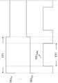
图3是在帧周期FP1内,显示设备100所产生的信号时序图。在图3中,去模糊脉冲信号SIGMBR可以是具有单一脉冲的脉冲波,然而在一些其他实施例中,去模糊脉冲信号SIGMBR也可包含多个脉冲波。此外,在图3中,驱动电路140可以利用模拟的方式驱动背光模块120,此时驱动信号SIGD1至SIGDN可例如是电流信号,也就是说,驱动电路140会依据控制信号SIGC1的指示,提供具有对应电流大小的驱动信号SIGD1至SIGDN至背光区块1221至122N,使得背光区块1221至122N能够发出对应亮度的光。在此情况下,当驱动信号SIGD1的电流越大时,背光区块1221也将对应地发出亮度越大的光。然而,在一些其他实施例中,驱动电路140也可以利用数字的方式驱动背光模块120,此时驱动信号SIGD1至SIGDN可以是具有固定电流大小的脉冲宽度调制信号。也就是说,驱动电路140可依据控制信号SIGC1的指示产生具有特定频率及对应工作周期(duty cycle)大小的驱动信号SIGD1至SIGDN至背光区块1221至122N,使得背光区块1221至122N能够发出对应亮度的光。在此情况下,当驱动信号SIGD1的工作周期越接近100%时,背光区块1221也将对应地发出亮度越大的光。FIG. 3 is a timing diagram of signals generated by the
再者,在图3中,驱动电路140可以持续地输出驱动信号SIGD1至SIGDN,然而背光模块120可以利用逻辑电路,例如与门(AND gate),来对驱动信号SIGD1至SIGDN以及去模糊脉冲信号SIGMBR进行逻辑与的运算,使得背光区块1221至122N仅会在去模糊脉冲信号SIGMBR处于高电位的发光时段EP1内,依据驱动信号SIGD1至SIGDN发出对应亮度的光。Moreover, in FIG. 3 , the driving
在一些实施例中,方法200还可动态地调整显示设备100在更新图像时的刷新率,例如将图像更新的刷新率调高(例如从60赫兹调整为120赫兹),以提升呈现图像的质量,或将图像更新的刷新率调降以减少功耗。在此情况下,当刷新率改变时,由于帧周期的长度也会随之改变,因此波形产生电路150也可依据显示设备100的刷新率来调整去模糊脉冲信号SIGMBR中所包含的脉冲数量、以及每一脉冲处于该高电位的持续时间长度。In some embodiments, the
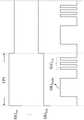
此外,当显示设备100的刷新率被动态调整时,若波形产生电路150并未对应调整去模糊脉冲信号SIGMBR的波形,就可能导致画面呈现的亮度不如预期。在此情况下,波形产生电路150也可在帧周期FP1内,在产生去模糊脉冲信号SIGMBR之后,产生补偿脉冲信号SIGCS至背光模块120,而背光区块1221至122N则也可在补偿脉冲信号SIGCS处于高电位时,依据驱动信号SIGD1至SIGDN发光。In addition, when the refresh rate of the
图4是在帧周期FP1内,显示设备100所产生的另一信号时序图。举例来说,当刷新率降低时,帧周期FP1的长度会提升,此时若去模糊脉冲信号SIGMBR处在高电位的时段并未对应拉长,就会使得背光区块1221至122N实际发光的时间比例变低,导致显示设备100的整体呈现的亮度偏低,此时波形产生电路150可以在产生去模糊脉冲信号SIGMBR之后,接续地产生补偿脉冲信号SIGCS,以增加背光区块1221至122N在帧周期FP1内的发光时间,达到亮度补偿的效果。在图4中,补偿脉冲信号SIGCS可包含至少一脉冲。FIG. 4 is a timing diagram of another signal generated by the
由于显示设备100可以利用波形产生电路150来产生补偿脉冲信号SIGCS,因此控制电路130无须另外通过串行外设接口来对驱动电路140传送其他的控制信号,从而能够简化控制电路130及驱动电路140的操作,并可减少因为控制信号延迟所导致之画面亮度不如预期和/或画面闪烁的异常状况。Since the
此外,在一些实施例中,波形产生电路150所产生的去模糊脉冲信号SIGMBR可具有的固定长度,而当刷新率产生变化时,波形产生电路150仅需要应调整补偿脉冲信号SIGCS所包含的脉冲数量多少,就可以确保背光模块120能够在每个帧周期内提供所需亮度的背光。如此一来,就无须另外调整去模糊脉冲信号SIGMBR的波形,而能够简化波形产生电路150的操作。In addition, in some embodiments, the deblurring pulse signal SIGMBR generated by the
综上所述,本公开所提供的显示设备及显示方法可以利用波形产生电路来产生去模糊脉冲信号及补偿脉冲信号,因此可以简化控制电路及驱动电路的操作,从而减少因为控制信号延迟所导致的画面亮度不如预期和/或画面闪烁的异常状况。To sum up, the display device and the display method provided by the present disclosure can use the waveform generation circuit to generate the deblurred pulse signal and the compensation pulse signal, so the operation of the control circuit and the driving circuit can be simplified, thereby reducing the delay caused by the delay of the control signal. The brightness of the screen is not as expected and/or the screen is flickering abnormally.
【符号说明】【Symbol Description】
100: 显示设备100: display device
110: 液晶显示面板110: Liquid crystal display panel
120: 背光模块120: Backlight module
1221至122N: 背光区块1221 to 122N: backlight blocks
130: 控制电路130: control circuit
140: 驱动电路140: drive circuit
150: 波形产生电路150: Waveform generation circuit
200: 方法200: method
DI: 显示数据DI: display data
EP1: 发光时段EP1: Luminous Period
FP1: 帧周期FP1: frame period
S210至S260: 步骤S210 to S260: Steps
SIGC1: 控制信号SIGC1 : Control signal
SIGD1至SIGDN: 驱动信号SIGD1 to SIGDN : Drive signal
SIGMBR: 去模糊脉冲信号SIGMBR : Deblurred Burst Signal
Claims (10)
Priority Applications (1)
| Application Number | Priority Date | Filing Date | Title |
|---|---|---|---|
| CN202110512024.5ACN115331635B (en) | 2021-05-11 | 2021-05-11 | Display device and display method |
Applications Claiming Priority (1)
| Application Number | Priority Date | Filing Date | Title |
|---|---|---|---|
| CN202110512024.5ACN115331635B (en) | 2021-05-11 | 2021-05-11 | Display device and display method |
Publications (2)
| Publication Number | Publication Date |
|---|---|
| CN115331635Atrue CN115331635A (en) | 2022-11-11 |
| CN115331635B CN115331635B (en) | 2025-09-19 |
Family
ID=83912119
Family Applications (1)
| Application Number | Title | Priority Date | Filing Date |
|---|---|---|---|
| CN202110512024.5AActiveCN115331635B (en) | 2021-05-11 | 2021-05-11 | Display device and display method |
Country Status (1)
| Country | Link |
|---|---|
| CN (1) | CN115331635B (en) |
Citations (6)
| Publication number | Priority date | Publication date | Assignee | Title |
|---|---|---|---|---|
| CN1936653A (en)* | 2005-09-20 | 2007-03-28 | 奇美电子股份有限公司 | Liquid crystal display and its driving method |
| US20120169949A1 (en)* | 2010-12-30 | 2012-07-05 | Lg Display Co., Ltd. | Stereoscopic image display |
| CN105047144A (en)* | 2015-09-08 | 2015-11-11 | 武汉华星光电技术有限公司 | Liquid crystal display device and backlight control method thereof |
| US20190164506A1 (en)* | 2017-11-30 | 2019-05-30 | Novatek Microelectronics Corp. | Synchronous backlight device and operation method thereof |
| US20190244572A1 (en)* | 2018-02-02 | 2019-08-08 | Apple Inc. | Pulsed backlight systems and methods |
| CN110379377A (en)* | 2019-07-04 | 2019-10-25 | 苏州佳世达电通有限公司 | The display methods and display device that dynamic fuzzy improves and do not flash |
- 2021
- 2021-05-11CNCN202110512024.5Apatent/CN115331635B/enactiveActive
Patent Citations (6)
| Publication number | Priority date | Publication date | Assignee | Title |
|---|---|---|---|---|
| CN1936653A (en)* | 2005-09-20 | 2007-03-28 | 奇美电子股份有限公司 | Liquid crystal display and its driving method |
| US20120169949A1 (en)* | 2010-12-30 | 2012-07-05 | Lg Display Co., Ltd. | Stereoscopic image display |
| CN105047144A (en)* | 2015-09-08 | 2015-11-11 | 武汉华星光电技术有限公司 | Liquid crystal display device and backlight control method thereof |
| US20190164506A1 (en)* | 2017-11-30 | 2019-05-30 | Novatek Microelectronics Corp. | Synchronous backlight device and operation method thereof |
| US20190244572A1 (en)* | 2018-02-02 | 2019-08-08 | Apple Inc. | Pulsed backlight systems and methods |
| CN110379377A (en)* | 2019-07-04 | 2019-10-25 | 苏州佳世达电通有限公司 | The display methods and display device that dynamic fuzzy improves and do not flash |
Also Published As
| Publication number | Publication date |
|---|---|
| CN115331635B (en) | 2025-09-19 |
Similar Documents
| Publication | Publication Date | Title |
|---|---|---|
| US20200051484A1 (en) | Backlight device and display device provided with same | |
| CN111833802B (en) | Display device | |
| US11631375B2 (en) | Display equipment and operation method thereof and backlight control device that solves flicker phenomenon of variable refresh rate video frame | |
| JP4527958B2 (en) | Liquid crystal display | |
| US20070211014A1 (en) | Methods and Circuits for Synchronous Operation of Display Backlighting | |
| US10770023B2 (en) | Dynamic overdrive for liquid crystal displays | |
| US9728151B2 (en) | Display panel driving and scanning method and system | |
| US10872558B2 (en) | Image display processing method and device, display device and non-volatile storage medium | |
| CN109215586B (en) | Display method and display system for reducing double image effect | |
| JP2005148708A (en) | Driving method and driving apparatus for liquid crystal display device | |
| WO2022141567A1 (en) | Display panel and electronic device | |
| US11417288B1 (en) | Control circuit and control method applicable to display panel | |
| KR20090098656A (en) | Liquid crystal display drive device and driving method | |
| US11651746B2 (en) | Backlight driving device and operating method thereof | |
| US10877315B2 (en) | Backlight and display device provided with same | |
| TWI768828B (en) | Display device and displaying method | |
| US20120327140A1 (en) | Liquid crystal display for reducing motion blur | |
| WO2021121435A1 (en) | Method for improving display image quality and display device | |
| CN115331635B (en) | Display device and display method | |
| KR100631018B1 (en) | Driving Method of LCD | |
| KR20100030703A (en) | Method of driving backlight unit and liquid crystal display device using the same | |
| CN118131519B (en) | Gray compensation method and device, backlight driver and display device | |
| JP2004170996A (en) | Multi-light source driving device, liquid crystal display device and its driving method | |
| CN114974149B (en) | Control circuit and control method applied to display panel | |
| KR101066497B1 (en) | LCD Display |
Legal Events
| Date | Code | Title | Description |
|---|---|---|---|
| PB01 | Publication | ||
| PB01 | Publication | ||
| SE01 | Entry into force of request for substantive examination | ||
| SE01 | Entry into force of request for substantive examination | ||
| GR01 | Patent grant | ||
| GR01 | Patent grant |