CN115330734A - Automatic robot repair welding system based on three-dimensional target detection and point cloud defect completion - Google Patents
Automatic robot repair welding system based on three-dimensional target detection and point cloud defect completionDownload PDFInfo
- Publication number
- CN115330734A CN115330734ACN202210994552.3ACN202210994552ACN115330734ACN 115330734 ACN115330734 ACN 115330734ACN 202210994552 ACN202210994552 ACN 202210994552ACN 115330734 ACN115330734 ACN 115330734A
- Authority
- CN
- China
- Prior art keywords
- point cloud
- repair welding
- workpiece
- defect
- completion
- Prior art date
- Legal status (The legal status is an assumption and is not a legal conclusion. Google has not performed a legal analysis and makes no representation as to the accuracy of the status listed.)
- Pending
Links
Images


Classifications
- G—PHYSICS
- G06—COMPUTING OR CALCULATING; COUNTING
- G06T—IMAGE DATA PROCESSING OR GENERATION, IN GENERAL
- G06T7/00—Image analysis
- G06T7/0002—Inspection of images, e.g. flaw detection
- G06T7/0004—Industrial image inspection
- G06T7/001—Industrial image inspection using an image reference approach
- G—PHYSICS
- G06—COMPUTING OR CALCULATING; COUNTING
- G06T—IMAGE DATA PROCESSING OR GENERATION, IN GENERAL
- G06T7/00—Image analysis
- G06T7/70—Determining position or orientation of objects or cameras
- G06T7/73—Determining position or orientation of objects or cameras using feature-based methods
- G—PHYSICS
- G06—COMPUTING OR CALCULATING; COUNTING
- G06T—IMAGE DATA PROCESSING OR GENERATION, IN GENERAL
- G06T7/00—Image analysis
- G06T7/80—Analysis of captured images to determine intrinsic or extrinsic camera parameters, i.e. camera calibration
- G—PHYSICS
- G06—COMPUTING OR CALCULATING; COUNTING
- G06V—IMAGE OR VIDEO RECOGNITION OR UNDERSTANDING
- G06V10/00—Arrangements for image or video recognition or understanding
- G06V10/40—Extraction of image or video features
- G06V10/44—Local feature extraction by analysis of parts of the pattern, e.g. by detecting edges, contours, loops, corners, strokes or intersections; Connectivity analysis, e.g. of connected components
- G06V10/443—Local feature extraction by analysis of parts of the pattern, e.g. by detecting edges, contours, loops, corners, strokes or intersections; Connectivity analysis, e.g. of connected components by matching or filtering
- G—PHYSICS
- G06—COMPUTING OR CALCULATING; COUNTING
- G06V—IMAGE OR VIDEO RECOGNITION OR UNDERSTANDING
- G06V10/00—Arrangements for image or video recognition or understanding
- G06V10/70—Arrangements for image or video recognition or understanding using pattern recognition or machine learning
- G06V10/764—Arrangements for image or video recognition or understanding using pattern recognition or machine learning using classification, e.g. of video objects
- G—PHYSICS
- G06—COMPUTING OR CALCULATING; COUNTING
- G06V—IMAGE OR VIDEO RECOGNITION OR UNDERSTANDING
- G06V10/00—Arrangements for image or video recognition or understanding
- G06V10/70—Arrangements for image or video recognition or understanding using pattern recognition or machine learning
- G06V10/82—Arrangements for image or video recognition or understanding using pattern recognition or machine learning using neural networks
- G—PHYSICS
- G06—COMPUTING OR CALCULATING; COUNTING
- G06T—IMAGE DATA PROCESSING OR GENERATION, IN GENERAL
- G06T2207/00—Indexing scheme for image analysis or image enhancement
- G06T2207/10—Image acquisition modality
- G06T2207/10024—Color image
- G—PHYSICS
- G06—COMPUTING OR CALCULATING; COUNTING
- G06T—IMAGE DATA PROCESSING OR GENERATION, IN GENERAL
- G06T2207/00—Indexing scheme for image analysis or image enhancement
- G06T2207/10—Image acquisition modality
- G06T2207/10028—Range image; Depth image; 3D point clouds
- G—PHYSICS
- G06—COMPUTING OR CALCULATING; COUNTING
- G06T—IMAGE DATA PROCESSING OR GENERATION, IN GENERAL
- G06T2207/00—Indexing scheme for image analysis or image enhancement
- G06T2207/20—Special algorithmic details
- G06T2207/20024—Filtering details
- G—PHYSICS
- G06—COMPUTING OR CALCULATING; COUNTING
- G06T—IMAGE DATA PROCESSING OR GENERATION, IN GENERAL
- G06T2207/00—Indexing scheme for image analysis or image enhancement
- G06T2207/20—Special algorithmic details
- G06T2207/20084—Artificial neural networks [ANN]
- G—PHYSICS
- G06—COMPUTING OR CALCULATING; COUNTING
- G06V—IMAGE OR VIDEO RECOGNITION OR UNDERSTANDING
- G06V2201/00—Indexing scheme relating to image or video recognition or understanding
- G06V2201/07—Target detection
Landscapes
- Engineering & Computer Science (AREA)
- Theoretical Computer Science (AREA)
- Computer Vision & Pattern Recognition (AREA)
- Physics & Mathematics (AREA)
- General Physics & Mathematics (AREA)
- Evolutionary Computation (AREA)
- Multimedia (AREA)
- Artificial Intelligence (AREA)
- Health & Medical Sciences (AREA)
- Computing Systems (AREA)
- Databases & Information Systems (AREA)
- General Health & Medical Sciences (AREA)
- Medical Informatics (AREA)
- Software Systems (AREA)
- Quality & Reliability (AREA)
- Numerical Control (AREA)
Abstract
Translated fromChinese
Description
Translated fromChinese技术领域technical field
本发明属于人工智能领域和工业自动化领域,具体涉及一种基于三维目标检测和点云缺陷补全的自动化机器人补焊系统,可以实现焊接工件的品种高精度识别与板件缺陷补焊。The invention belongs to the fields of artificial intelligence and industrial automation, and specifically relates to an automatic robot repair welding system based on three-dimensional target detection and point cloud defect completion, which can realize high-precision identification of types of welding workpieces and repair welding of plate defects.
背景技术Background technique
补焊技术作为一种基础的缺陷板件加工技术,在工业实际生产作业中运用非常广泛,已经逐渐成为影响传统工业制造领域的关键性因素之一。伴随着焊接机器人与传感器等配套产品的快速更新换代以及计算机视觉三维检测技术的日益发展,关于如何提升三维目标检测准确性、提高补焊工件的质量稳定性现已成为重点研究方向之一。Repair welding technology, as a basic defective plate processing technology, is widely used in actual industrial production operations, and has gradually become one of the key factors affecting the traditional industrial manufacturing field. With the rapid upgrading of supporting products such as welding robots and sensors and the increasing development of
三维点云数据的获取方法相对快捷,同时三维点云数据的采集不受光照影响,也规避了二维图像遇到的光照、姿态等问题,因此基于点云数据的三维物体识别也引起了人们的重视。三维点云物体识别方法多是通过提取物体的特征点几何属性、形状属性、结构属性或者多种属性的组合等特征进行比对、学习,从而完成物体的识别与分类。The acquisition method of 3D point cloud data is relatively fast. At the same time, the acquisition of 3D point cloud data is not affected by illumination, and also avoids the problems of illumination and posture encountered in 2D images. Therefore, 3D object recognition based on point cloud data has also attracted people's attention. attention. Most of the 3D point cloud object recognition methods are to compare and learn by extracting the geometric attributes, shape attributes, structural attributes or combinations of various attributes of the object's feature points, so as to complete the object recognition and classification.
随着焊接机器人技术、三维目标检测、深度学习、PCL等技术的快速发展,基于视觉的智能识别与检测技术在现代机器人焊接领域的应用日渐增多,极大提高了焊接机器人的智能化以及自动化程度。缺陷补焊技术是实现焊接智能化与自动化的核心技术之一,高效且精准的焊枪补焊操作对于保障成品工件的质量稳定性具有极其重要的意义。为了实现复杂环境下焊接机器人的自动化补焊操作,要求焊接机器人必须能够准确识别复杂环境下工件缺陷位置并优化焊枪姿态进行精准补焊。With the rapid development of welding robot technology, three-dimensional target detection, deep learning, PCL and other technologies, the application of vision-based intelligent recognition and detection technology in the field of modern robot welding is increasing, which greatly improves the intelligence and automation of welding robots. . Defect repair welding technology is one of the core technologies to realize welding intelligence and automation. Efficient and accurate welding torch repair welding operation is of great significance to ensure the quality stability of finished workpieces. In order to realize the automatic repair welding operation of the welding robot in the complex environment, the welding robot must be able to accurately identify the defect position of the workpiece in the complex environment and optimize the posture of the welding torch for precise repair welding.
发明内容Contents of the invention
本发明提供了一种基于三维目标检测和点云缺陷补全的自动化机器人补焊系统,整套系统通过ROS进行通信。通过嵌入坐标注意力机制的Lidar-RCNN++网络模型实现在多个工件中选取指定工件的三维目标检测,后结合PointNet网络进行三维缺陷检测,最后采用PF-NET网络进行缺陷点云补全,并结合PCL点云处理库进行缺陷补焊,本系统是一种可针对大型焊接场景的工件进行缺陷补焊的系统。本发明以Ubuntu18.04为操作系统,以多个深度学习算法为基础神经网络框架,结合PCL点云处理开源库进行软件开发,建立自动化补焊系统。在人机交互方面,设计上位机交互模块,结合QT图形界面进行上位机功能开发,建立的可视化界面可显示缺陷工件点云、点云补全效果和缺陷补焊结果,具有人机交互性好、结果可视化能力强等特点。通过本发明,可以解决在大型焊接场景下高精度识别工件种类以及工件缺陷补焊的问题,使现代焊接作业进一步迈向自动化与智能化。The invention provides an automatic robot repair welding system based on three-dimensional target detection and point cloud defect completion, and the whole system communicates through ROS. Through the Lidar-RCNN++ network model embedded in the coordinate attention mechanism, the 3D target detection of the specified workpiece is selected from multiple workpieces, and then combined with the PointNet network for 3D defect detection, and finally the PF-NET network is used for defect point cloud completion, combined with The PCL point cloud processing library performs defect repair welding. This system is a system that can perform defect repair welding for workpieces in large-scale welding scenarios. The present invention uses Ubuntu 18.04 as the operating system, uses multiple deep learning algorithms as the basic neural network framework, combines the PCL point cloud processing open source library for software development, and establishes an automatic repair welding system. In terms of human-computer interaction, the upper computer interaction module is designed, and the function development of the upper computer is carried out in combination with the QT graphical interface. The established visual interface can display the point cloud of the defective workpiece, the effect of point cloud completion and the result of defect repair welding, which has good human-computer interaction. , Strong results visualization ability and so on. The present invention can solve the problems of high-precision identification of workpiece types and repair welding of workpiece defects in a large-scale welding scene, so that modern welding operations can be further automated and intelligent.
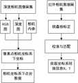
本发明通过模块化的方式设计了整体系统,主要可分为5个模块:数据采集模块、三维目标检测模块、三维缺陷检测模块、工件补焊模块,同时设计上位机交互系统可以显示缺陷工件点云、点云补全效果和缺陷补焊结果。数据采集模块使用深度相机获取有多个工件的场景图像,再通过深度相机采集到的RGB图、深度图与相机内参结合,计算像素点在相机坐标系下的坐标,利用障碍点在相机坐标系下的坐标结合相机内参外参获得相机坐标系下的点云数据。同时结合红外相机棋盘格标定,通过校准与匹配获取坐标系转换信息R和T。三维目标检测模块首先对原始场景的点云数据进行降采样、离群点去除、聚类等预处理,再采用基于坐标注意力机制并结合使用Virtual points的Lidar-RCNN++网络模型实现在多个不同种类工件点云中选取指定的工件点云数据。三维缺陷检测模块首先通过预设无缺陷的指定工件标签,然后利用PointNet网络模型进行模型分类,将有缺陷的点云数据与无缺陷点云数据区分开,再将有缺陷的点云数据提取出来,以供补全算法的实际工作开展。工件补焊模块首先通过PF-NET网络进行缺陷点云补全,后结合PCL库算法筛选出补全前与补全后的点云数据重复点,提取出缺陷工件模型的待补焊点的点云数据,根据关键点选取和朝向计算,从而精准的进行TCP焊枪补焊操作。上位机交互系统实现了深度相机传感器数据的获取与处理,可以显示传感器拍摄到的RGB图、深度图、点云数据图,可以模拟补焊全过程的仿真图,可以提供手眼标定数值的修正界面。通过本专利,解决了工件在出厂前次品率检测的问题,同时有效降低了焊接作业所需的人工成本,并且可以在极大程度上避免焊接作业中重大事故的发生,提高了实际工业生产过程的安全性和自动化程度,保障了成品工件的质量稳定性。The present invention designs the overall system in a modular manner, which can be mainly divided into five modules: data acquisition module, three-dimensional target detection module, three-dimensional defect detection module, and workpiece repair welding module. At the same time, the interactive system of the upper computer is designed to display defective workpiece points Cloud, point cloud completion effect and defect repair welding results. The data acquisition module uses the depth camera to obtain scene images with multiple workpieces, and then combines the RGB image and depth image collected by the depth camera with the internal reference of the camera to calculate the coordinates of the pixel points in the camera coordinate system, and use the obstacle points in the camera coordinate system The coordinates below are combined with the internal and external parameters of the camera to obtain the point cloud data in the camera coordinate system. At the same time, combined with the infrared camera checkerboard calibration, the coordinate system conversion information R and T are obtained through calibration and matching. The 3D target detection module first performs preprocessing on the point cloud data of the original scene, such as downsampling, outlier point removal, clustering, etc., and then uses the Lidar-RCNN++ network model based on the coordinate attention mechanism combined with Virtual points to implement in multiple different Select the specified workpiece point cloud data from the type workpiece point cloud. The 3D defect detection module first presets the specified workpiece label without defect, and then uses the PointNet network model to classify the model, distinguishes the defective point cloud data from the non-defective point cloud data, and then extracts the defective point cloud data , for the actual work of the completion algorithm. The workpiece repair welding module first completes the defect point cloud through the PF-NET network, and then combines the PCL library algorithm to screen out the duplicate points of the point cloud data before and after completion, and extract the points to be repaired of the defective workpiece model Cloud data, according to key point selection and orientation calculation, so as to accurately carry out TCP welding torch repair welding operation. The upper computer interactive system realizes the acquisition and processing of depth camera sensor data, can display the RGB image, depth image, and point cloud data image captured by the sensor, can simulate the simulation image of the whole process of repair welding, and can provide a correction interface for hand-eye calibration values . Through this patent, the problem of detecting the defective rate of the workpiece before leaving the factory is solved, and at the same time, the labor cost required for the welding operation is effectively reduced, and the occurrence of major accidents in the welding operation can be avoided to a great extent, and the actual industrial production is improved. The safety and automation of the process ensure the quality stability of the finished workpiece.
本发明解决其技术问题所采用的技术方案如下:The technical solution adopted by the present invention to solve its technical problems is as follows:
在数据采集模块中,使用深度相机获取有多个工件的场景图像,再利用RGBD相机采集到的RGB图、深度图与相机内参结合,计算出每个像素点在相机坐标系下的坐标,最后利用障碍点在相机坐标系下的坐标结合相机内参外参获得相机坐标系下的点云数据。同时结合张正友标定法完成手眼标定,求解出内参矩阵、外参矩阵、畸变参数,最后利用L-M(Levenberg-Marquardt)算法对上述参数进行优化,计算得到相机坐标系到机械臂末端坐标系的旋转矩阵和平移量。In the data acquisition module, the depth camera is used to obtain scene images with multiple workpieces, and then the RGB image and depth image collected by the RGBD camera are combined with the internal reference of the camera to calculate the coordinates of each pixel in the camera coordinate system, and finally The point cloud data in the camera coordinate system is obtained by using the coordinates of the obstacle point in the camera coordinate system combined with the internal and external parameters of the camera. At the same time, combined with the Zhang Zhengyou calibration method to complete the hand-eye calibration, solve the internal parameter matrix, external parameter matrix, and distortion parameters, and finally use the L-M (Levenberg-Marquardt) algorithm to optimize the above parameters, and calculate the rotation matrix from the camera coordinate system to the end coordinate system of the robot arm and translation.
在三维目标检测模块中,将数据采集模块中得到的相机坐标系下的点云数据进行点云预处理,利用RandomSample随机降采样的方法减少点云数量,加速算法执行速度,利用RadiusOutlierRemoval半径滤波的方法去除离群点,结合区域生长聚类算法分割出不同种类工件的点云数据。在完成了点云预处理之后,使用改进了嵌入坐标注意力机制的Lidar-RCNN++三维目标检测网络模型检测出多个不同种类工件点云中指定的工件点云数据。In the 3D target detection module, the point cloud data in the camera coordinate system obtained in the data acquisition module is preprocessed, and the RandomSample random downsampling method is used to reduce the number of point clouds, accelerate the algorithm execution speed, and use the RadiusOutlierRemoval radius filter The method removes outliers, and combines the region growing clustering algorithm to segment the point cloud data of different types of workpieces. After completing the point cloud preprocessing, use the Lidar-RCNN++ 3D target detection network model with an improved embedded coordinate attention mechanism to detect the specified workpiece point cloud data in multiple different types of workpiece point clouds.
在三维缺陷检测模块中,首先通过预设的标签自动去除三维目标检测中可能存在的错误检测结果,然后利用PointNet网络模型通过上采样和Max Pooling等操作对指定的工件点云数据进行模型分类,将工件分为需要补焊和不需要补焊的两类工件,最后将有缺陷的工件点云数据提取出来,以供后续点云补全使用。In the 3D defect detection module, firstly, the false detection results that may exist in the 3D target detection are automatically removed through the preset labels, and then the PointNet network model is used to classify the specified workpiece point cloud data through operations such as upsampling and Max Pooling. The workpieces are divided into two types of workpieces that need repair welding and those that do not need repair welding. Finally, the point cloud data of defective workpieces is extracted for subsequent point cloud completion.
在工件补焊模块中,首先采用PF-NET点云补全网络进行训练和缺陷点云补全,后结合PCL库去除重复点的算法筛选出补全前与补全后的点云数据重复点,从而提取出缺陷工件模型的待补焊点的点云数据,根据对三维坐标的X、Y、Z坐标进行关键点选取判断出补焊起点与终点,最后结合补焊点云数据法向量计算和空间坐标系转换等进行焊枪朝向计算,从而精准的进行TCP焊枪补焊操作。In the workpiece repair welding module, first use the PF-NET point cloud completion network for training and defect point cloud completion, and then combine the algorithm of PCL library to remove duplicate points to filter out the duplicate points of the point cloud data before and after completion , so as to extract the point cloud data of the welding point to be repaired in the defective workpiece model, and judge the starting point and end point of the repair welding according to the key point selection of the X, Y, Z coordinates of the three-dimensional coordinates, and finally combine the normal vector calculation of the repair welding point cloud data And space coordinate system conversion, etc. to calculate the welding torch orientation, so as to accurately carry out the TCP welding torch repair welding operation.
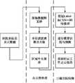
在上位机交互系统中,实现了深度相机传感器数据的获取与处理,利用Qt图形用户界面应用程序开发框架设计了可视化界面,集成了数据采集、工件识别、点云补全、工件补焊以及手眼标定修正的功能,通过QT的“信号——槽”机制,点击对应按钮即可完成操作,并且可以显示深度相机拍摄到的RGB图、深度图、点云数据图,可以模拟补焊全过程的仿真图,可以提供手眼标定数值的修正界面。In the upper computer interactive system, the acquisition and processing of the depth camera sensor data is realized, and the visual interface is designed by using the Qt graphical user interface application development framework, which integrates data acquisition, workpiece identification, point cloud completion, workpiece repair welding and hand-eye The function of calibration correction can be completed by clicking the corresponding button through QT's "signal-slot" mechanism, and can display the RGB image, depth image, and point cloud data image captured by the depth camera, which can simulate the whole process of repair welding The simulation diagram can provide a correction interface for hand-eye calibration values.
本发明采用以上技术方案后与现技术相比,具有以下有益效果:Compared with the prior art, the present invention has the following beneficial effects after adopting the above technical scheme:
(1)本发明通过嵌入坐标注意力机制的深度学习算法建立适用于三维目标检测的Lidar-RCNN++网络模型,通过智能化处理的方式提升了不同工件模型进行目标工件检测的准确性;(1) The present invention establishes a Lidar-RCNN++ network model suitable for three-dimensional target detection through a deep learning algorithm embedded in a coordinate attention mechanism, and improves the accuracy of target workpiece detection by different workpiece models through intelligent processing;
(2)本发明采用了基于关键点选取和多个空间坐标系转换优化焊枪朝向的方法,大大提升了补焊作业的精确度和稳定性;(2) The present invention adopts the method of optimizing the orientation of the welding torch based on key point selection and conversion of multiple spatial coordinate systems, which greatly improves the accuracy and stability of the repair welding operation;
(3)本发明在极大程度上代替了工件检测场景下技术人员进行手动补焊,同时设计上位机交互系统,可以方便查看缺陷补焊系统作业过程和进行手眼标定数值修改。(3) The present invention largely replaces manual repair welding by technicians in the scene of workpiece inspection, and at the same time, the interactive system of the host computer is designed to facilitate viewing of the defect repair welding system operation process and modifying hand-eye calibration values.
附图说明Description of drawings
图1为本发明实施例中的自动化机器人补焊系统的结构框图。Fig. 1 is a structural block diagram of an automatic robot repair welding system in an embodiment of the present invention.
图2为本发明实施例中的系统结构示意图。Fig. 2 is a schematic diagram of the system structure in the embodiment of the present invention.
图3为本发明实施例中的缺陷补焊模型示意图。Fig. 3 is a schematic diagram of a defect repair welding model in an embodiment of the present invention.
图4为本发明实施例中的数据采集模块示意图。Fig. 4 is a schematic diagram of a data acquisition module in an embodiment of the present invention.
图5为本发明实施例中的三维目标检测模块示意图。Fig. 5 is a schematic diagram of a three-dimensional object detection module in an embodiment of the present invention.
图6为本发明实施例中的三维缺陷检测模块示意图。Fig. 6 is a schematic diagram of a three-dimensional defect detection module in an embodiment of the present invention.
图7为本发明实施例中的工件补焊模块示意图。Fig. 7 is a schematic diagram of the workpiece repair welding module in the embodiment of the present invention.
图8为本发明实施例中的人机交互界面示意图。Fig. 8 is a schematic diagram of the human-computer interaction interface in the embodiment of the present invention.
图9为本发明实施例中的PointNet网络结构示意图。FIG. 9 is a schematic diagram of the PointNet network structure in the embodiment of the present invention.
图10为本发明实施例中的PF-Net网络结构示意图。FIG. 10 is a schematic diagram of a PF-Net network structure in an embodiment of the present invention.
图11为本发明实施例中的Lidar RCNN++结构示意图。Fig. 11 is a schematic diagram of the structure of Lidar RCNN++ in the embodiment of the present invention.
图12为本发明实施例中的工件点云可视化及参数修改界面图。Fig. 12 is an interface diagram of workpiece point cloud visualization and parameter modification in the embodiment of the present invention.
图13为本发明实施例中的模拟实际焊接测试界面图。Fig. 13 is an interface diagram of the simulated actual welding test in the embodiment of the present invention.
图14为本发明实施例中的点云数据预处理流程示意图。Fig. 14 is a schematic diagram of the point cloud data preprocessing flow in the embodiment of the present invention.
图15为本发明实施例中的数据标注示意图。Fig. 15 is a schematic diagram of data labeling in the embodiment of the present invention.
图16为本发明实施例中的条焊识别实操示意图。Fig. 16 is a schematic diagram of the practical operation of bar welding identification in the embodiment of the present invention.
图17为本发明实施例中的补焊测试实操示意图。Fig. 17 is a schematic diagram of the practical operation of the repair welding test in the embodiment of the present invention.
具体实施方式Detailed ways
下面结合说明书附图对本发明的技术方案做进一步的详细说明。The technical solution of the present invention will be further described in detail below in conjunction with the accompanying drawings.
如图1和图2所示,本发明包括数据采集模块、三维目标检测模块、三维缺陷检测模块、工件补焊模块和人机交互界面模块五个部分,模块间采用ROS发布订阅的形式进行全局通信。其中数据采集模块利用深度相机获取有多个工件的场景图像,再通过深度相机采集到的RGB图、深度图与相机内参结合,计算像素点在相机坐标系下的坐标,利用障碍点在相机坐标系下的坐标结合相机内参外参获得相机坐标系下的点云数据。三维目标检测模块首先对三维点云数据进行一系列预处理操作,后采用基于坐标注意力(CA)机制并结合使用Virtual points的Lidar-RCNN++网络模型实现在多个不同种类工件点云中选取指定的工件点云数据。三维缺陷检测模块首先预设无缺陷的工件标签,接着利用PointNet网络模型进行模型分类,将有缺陷的点云数据与无缺陷点云数据区分开,获取到缺陷点云数据。工件补焊模块首先通过PF-NET网络进行缺陷点云补全,后结合PCL库算法筛选出补全前后点云重复点,去除重复点得到待补焊的点云数据,根据关键点选取和焊枪朝向计算,从而精准的进行TCP焊枪补焊操作。人机交互系统集成了数据采集、工件识别、点云补全、工件补焊以及手眼标定修正的功能,增强了缺陷工件补焊作业的可视性。各模块相互协作,可以实现本系统的正常运转。As shown in Figures 1 and 2, the present invention includes five parts: a data acquisition module, a three-dimensional target detection module, a three-dimensional defect detection module, a workpiece repair welding module, and a human-computer interaction interface module. communication. The data acquisition module uses the depth camera to obtain scene images with multiple workpieces, and then combines the RGB image and depth image collected by the depth camera with the internal reference of the camera to calculate the coordinates of the pixel points in the camera coordinate system, and use the obstacle points in the camera coordinates The coordinates in the camera coordinate system are combined with the internal and external parameters of the camera to obtain the point cloud data in the camera coordinate system. The 3D target detection module firstly performs a series of preprocessing operations on the 3D point cloud data, and then uses the coordinate attention (CA) mechanism based on the Lidar-RCNN++ network model using Virtual points to select and specify points from multiple different types of workpiece point clouds. Workpiece point cloud data. The 3D defect detection module first presets the label of the workpiece without defects, and then uses the PointNet network model to classify the model, distinguishes the defective point cloud data from the non-defective point cloud data, and obtains the defective point cloud data. The workpiece repair welding module first completes the defect point cloud through the PF-NET network, and then combines the PCL library algorithm to screen out the point cloud duplicate points before and after the completion, and remove the duplicate points to obtain the point cloud data to be repaired. Orientation calculation, so as to accurately carry out the repair welding operation of TCP welding torch. The human-computer interaction system integrates the functions of data collection, workpiece identification, point cloud completion, workpiece repair welding, and hand-eye calibration correction, which enhances the visibility of defective workpiece repair welding operations. Each module cooperates with each other to realize the normal operation of the system.
以下详细叙述各模块实现方法及功能:The implementation methods and functions of each module are described in detail as follows:
本系统缺陷补焊采用点焊和条焊相结合,为了方便各模块功能叙述,选择如图3所示的点焊类型缺陷补焊为例,但本系统并不局限于此,可以适用于所有点焊和条焊的场景。The defect repair welding of this system adopts the combination of spot welding and strip welding. In order to facilitate the description of the functions of each module, the defect repair welding of the spot welding type as shown in Figure 3 is taken as an example, but the system is not limited to this, and can be applied to all Scenarios for spot and bar welding.
数据采集模块如图4所示,本模块可主要分为点云数据采集、手眼标定两部分。The data acquisition module is shown in Figure 4. This module can be mainly divided into two parts: point cloud data acquisition and hand-eye calibration.
(1)点云数据采集部分首先使用RGBD相机获取有多个工件的场景图像,将采集到的RGB图、深度图与相机内参结合,根据RGB图像提供的像素点坐标系下的X、Y坐标(公式中的u、v)和相机内参求出相机坐标系下的X、Y坐标值,同时深度图直接提供相机坐标系的Z坐标值,结合两者得到相机坐标系下的坐标P=[XYZ]T,相机坐标系下的障碍物点的坐标,就是点云传感器数据,也就是相机坐标系下的点云数据。(1) The point cloud data acquisition part first uses the RGBD camera to obtain the scene image with multiple workpieces, combines the collected RGB image and depth image with the internal reference of the camera, and according to the X and Y coordinates in the pixel coordinate system provided by the RGB image (u, v in the formula) and camera internal parameters to obtain the X and Y coordinate values in the camera coordinate system, and at the same time, the depth map directly provides the Z coordinate value in the camera coordinate system, and combine the two to obtain the coordinate P in the camera coordinate system = [ XYZ]T , the coordinates of the obstacle point in the camera coordinate system, is the point cloud sensor data, that is, the point cloud data in the camera coordinate system.
相机坐标系P与像素坐标系Puv下的点的坐标的关系公式,式中的fx为每个像素在图像平面x方向上的物理尺寸的倒数、fy为每个像素在图像平面y方向上的物理尺寸的倒数、cx、cy分别为图像坐标系原点在像素坐标系下的坐标:The relationship formula between the camera coordinate system P and the coordinates of the point under the pixel coordinate system Puv , where fx is the reciprocal of the physical size of each pixel in the image plane x direction, and fy is the image plane y of each pixel The reciprocal of the physical size in the direction, cx , cyy are the coordinates of the origin of the image coordinate system in the pixel coordinate system:

将上式整理后具体的求解公式如下:After finishing the above formula, the specific solution formula is as follows:


Z=d (4)Z=d (4)
一般来说,公式中点在相机坐标系下的Z值就是相机测出的深度值d,即就是真实点到相机平面的距离,如果不是可以加倍数补偿。(2)手眼标定部分首先采集22mm方格大小的标定板图像200张,对图像中的特征点如标定板角点进行检测,得到标定板角点的像素坐标值,根据已知的棋盘格大小和世界坐标系原点,计算得到标定板角点的物理坐标值,根据物理坐标值和像素坐标值的关系,求出H矩阵,进而构造v矩阵,求解B矩阵,利用B矩阵求解相机内参矩阵A,最后求解每张图片对应的相机外参矩阵,从而得到R、T(R为旋转矩阵,T为平移量),同时可构造矩阵计算径向畸变参数;标定结束后,会得到内参矩阵、平移和旋转参数以及畸变参数,最后可利用L-M(Levenberg-Marquardt)算法对上述参数进行优化,计算得到相机坐标系到机械臂末端坐标系的旋转矩阵和平移量。Generally speaking, the Z value of the point in the formula in the camera coordinate system is the depth value d measured by the camera, that is, the distance from the real point to the camera plane. If not, it can be multiplied for compensation. (2) The hand-eye calibration part first collects 200 images of the calibration board with a size of 22mm square, and detects the feature points in the image, such as the corner points of the calibration board, to obtain the pixel coordinates of the corner points of the calibration board. According to the known checkerboard size and the origin of the world coordinate system, calculate the physical coordinate value of the corner point of the calibration board, calculate the H matrix according to the relationship between the physical coordinate value and the pixel coordinate value, and then construct the v matrix, solve the B matrix, and use the B matrix to solve the camera internal reference matrix A , and finally solve the camera external parameter matrix corresponding to each picture, so as to obtain R, T (R is the rotation matrix, T is the translation amount), and at the same time, the matrix can be constructed to calculate the radial distortion parameter; after the calibration, the internal parameter matrix, translation And the rotation parameters and distortion parameters, and finally the L-M (Levenberg-Marquardt) algorithm can be used to optimize the above parameters, and the rotation matrix and translation amount from the camera coordinate system to the end coordinate system of the manipulator can be calculated.
三维目标检测模块如图5所示,本模块可主要分为点云预处理、三维目标检测两部分。The 3D object detection module is shown in Figure 5. This module can be mainly divided into two parts: point cloud preprocessing and 3D object detection.
(1)点云预处理部分。这部分利用PCL点云处理开源库对点云数据进行点云数据降采样、离群点去除以及聚类分割这三步点云预处理操作。由于传感器获取的点云数据量庞大从而影响了算法的运行速度,采用了随机降采样的方法减少点云数量,指定选取原始点云数据中的80000个点,每个点被选到的概率相同,可以得到指定采样点数量的80000个点云,由于随机降采样后的点云数据可能会过滤掉一些具有重要信息的关键特征点,通过固定随机种子为20,以此生成固定的随机数序列,来保证随机降采样的科学性,在不损失点云重要特征的前提下,提高后续算法执行的速率。离群点去除采用RadiusOutlierRemoval半径滤波器,对点云中每个点Pi,确定一个半径为r的邻域(即以Pi为圆心,以r为圆心的球体),若邻域内的点数N<Nthreshold,则认为点Pi为噪声点并去除。聚类分割采用的是基于区域生长的聚类分割算法,首先设置一个空的种子点序列和一个空的聚类数组,选择种子点(曲率最小的点)并将其加入到种子点序列中;搜索当前种子点的邻域点,计算邻域点的法线与当前种子点的法线之间的夹角,小于平滑阈值的邻域点加入到当前区域;检查每一个邻域点的曲率,小于曲率阈值的邻域点加入到种子点序列中,并删除当前种子点,以新的种子点继续生长;重复进行以上生长过程,直到种子点序列被清空。此时,一个区域生长完成,并将其加入到聚类数组中;对剩余点重复进行以上步骤,直到遍历完所有点。通过以上基于PCL库的点云预处理算法,可分离出每个工件单独的点云数据。(1) Point cloud preprocessing part. This part uses the PCL point cloud processing open source library to perform three-step point cloud preprocessing operations on point cloud data, including point cloud data downsampling, outlier point removal, and cluster segmentation. Due to the large amount of point cloud data acquired by the sensor, which affects the running speed of the algorithm, a random down-sampling method is used to reduce the number of point clouds, and 80,000 points in the original point cloud data are specified to be selected, and each point has the same probability of being selected. , 80,000 point clouds with a specified number of sampling points can be obtained. Since the point cloud data after random downsampling may filter out some key feature points with important information, a fixed random number sequence is generated by fixing the random seed to 20 , to ensure the scientific nature of random downsampling, and improve the speed of subsequent algorithm execution without losing important features of the point cloud. Outlier removal uses the RadiusOutlierRemoval radius filter. For each point Pi in the point cloud, determine a neighborhood with a radius of r (that is, a sphere withPi as the center and r as the center). If the number of points in the neighborhood is N <Nthreshold , the point Pi is considered as a noise point and removed. The clustering segmentation adopts a clustering segmentation algorithm based on region growth. First, set an empty seed point sequence and an empty clustering array, select the seed point (the point with the smallest curvature) and add it to the seed point sequence; Search the neighbor points of the current seed point, calculate the angle between the normal of the neighbor point and the normal of the current seed point, and add the neighbor points smaller than the smoothing threshold to the current area; check the curvature of each neighbor point, Neighborhood points smaller than the curvature threshold are added to the seed point sequence, and the current seed point is deleted, and the new seed point continues to grow; the above growth process is repeated until the seed point sequence is cleared. At this point, the growth of a region is completed, and it is added to the clustering array; the above steps are repeated for the remaining points until all points are traversed. Through the above point cloud preprocessing algorithm based on the PCL library, the individual point cloud data of each workpiece can be separated.
(2)三维目标检测部分。这部分首先搭建嵌入基于坐标注意力(CA)机制并结合使用Virtual points的Lidar-RCNN++网络模型,如图5所示。Lidar-RCNN++又可以分为PointNet、Lidar-RCNN和Lidar-RCNN++三个阶段。PointNet是首个直接处理无序点云数据的深度模型框架,输入为包含n个点的三维点云数据,通过三维变换矩阵预测网络T-Net,估计出3*3的变换矩阵T,并将其作用于原始数据之上,实现了数据对齐。将对齐的数据以点为单位,通过一个共享参数的双层感知机模型shared mlp进行特征提取。每个点提取出64维的特征,后续再通过T-Net以及shared mlp,直到把特征的维度变为1024维,继而在特征空间的维度上进行MaxPooling,提取出点云的全局特征向量。Lidar-RCNN以PointNet网络为backbone主干网络,采用添加Virtual points添加虚点的方法解决了PointNet网络的proposal中空白部分无法在特征中表示,只会提取有扫描点部分的特征并融合,对proposal的大小没有任何感知能力的问题。Lidar-RCNN++在Lidar-RCNN网络模型的基础上嵌入坐标注意力机制,可以捕获全局上下文依赖关系,显著提高三维目标检测的精度。坐标注意力机制通过一种有效的方法来捕获位置信息和通道关系,以增强Mobile Network的特征表示。通过将三维全局池操作分解为三个一维编码过程,CA比其他具有轻量级属性的注意力方法(如SENet、CBAM和TA)效果更佳。(2) 3D object detection part. This part first builds a Lidar-RCNN++ network model embedded in a coordinate attention (CA) mechanism combined with Virtual points, as shown in Figure 5. Lidar-RCNN++ can be divided into three stages: PointNet, Lidar-RCNN and Lidar-RCNN++. PointNet is the first deep model framework that directly processes unordered point cloud data. The input is 3D point cloud data containing n points. Through the 3D transformation matrix prediction network T-Net, a 3*3 transformation matrix T is estimated, and the It acts on the original data to achieve data alignment. The aligned data is taken as a point, and feature extraction is performed through a shared parameter double-layer perceptron model shared mlp. Each point extracts a 64-dimensional feature, and then passes through T-Net and shared mlp until the dimension of the feature is changed to 1024 dimensions, and then performs MaxPooling on the dimension of the feature space to extract the global feature vector of the point cloud. Lidar-RCNN uses the PointNet network as the backbone backbone network, and uses the method of adding virtual points to add virtual points to solve the problem that the blank part of the proposal of the PointNet network cannot be represented in the feature, and only the features of the scanned point part will be extracted and fused. Size doesn't matter in any perceived capacity. Lidar-RCNN++ embeds a coordinate attention mechanism based on the Lidar-RCNN network model, which can capture global context dependencies and significantly improve the accuracy of 3D object detection. The coordinate attention mechanism enhances the feature representation of Mobile Network through an effective method to capture position information and channel relationship. By decomposing the 3D global pooling operation into three 1D encoding processes, CA outperforms other attention methods with lightweight properties such as SENet, CBAM, and TA.
Coordinate Attention通过精确的位置信息对通道关系和长期依赖性进行编码,具体操作分为Coordinate信息嵌入和Coordinate Attention生成2个步骤。Coordinate Attention encodes channel relationships and long-term dependencies through precise location information. The specific operation is divided into two steps: Coordinate information embedding and Coordinate Attention generation.
①全局池化方法通常用于通道注意编码空间信息的全局编码,但由于它将全局空间信息压缩到通道描述符中,导致难以保存位置信息。为了促使注意力模块能够捕捉具有精确位置信息的远程空间交互,CA采用了以下公式分解了全局池化,转化为一对一维特征编码操作:① The global pooling method is usually used for the global encoding of channel attention encoding spatial information, but since it compresses the global spatial information into the channel descriptor, it makes it difficult to preserve the positional information. In order to enable the attention module to capture long-range spatial interactions with precise location information, CA uses the following formula to decompose the global pooling and convert it into a one-dimensional feature encoding operation:

具体来说,给定输入X,首先使用尺寸为(H,1)或(1,W)的pooling kernel分别沿着水平坐标和垂直坐标对每个通道进行编码。因此,高度为h的第c通道的输出可以表示为:Specifically, given an input X, we first use a pooling kernel of size (H, 1) or (1, W) to encode each channel along the horizontal and vertical coordinates, respectively. Therefore, the output of the cth channel with height h can be expressed as:

同样,宽度为w的第c通道的输出可以写成:Likewise, the output of the cth channel of width w can be written as:

上述2种变换分别沿两个空间方向聚合特征,得到一对方向感知的特征图。这与在通道注意力方法中产生单一的特征向量的SE Block非常不同。这2种转换也允许注意力模块捕捉到沿着一个空间方向的长期依赖关系,并保存沿着另一个空间方向的精确位置信息,这有助于网络更准确地定位感兴趣的目标。The above two transformations aggregate features along two spatial directions respectively to obtain a pair of direction-aware feature maps. This is very different from SE Block which produces a single feature vector in channel attention methods. These 2 transformations also allow the attention module to capture long-term dependencies along one spatial direction and preserve precise location information along another spatial direction, which helps the network to more accurately localize objects of interest.
②Coordinate Attention生成通过信息嵌入中的变换后,该部分将上面的变换进行concatenate操作,然后使用卷积变换函数对其进行变换操作,式中δ是一个非线性激活函数,F1是1×1卷积变换函数,zh是高度为h的第c通道的输出,zw是宽度为w的第c通道的输出,σ是sigmoid函数,fh、fw为f沿空间维度拆分为两个独立的张量,Fw、Fh是1×1卷积变换将fh、fw转换为与输入X具有一样通道数的张量:② After the Coordinate Attention is generated through the transformation in the information embedding, this part performs the concatenate operation on the above transformation, and then uses the convolution transformation function to transform it, where δ is a nonlinear activation function, and F1 is 1×1 volume Product transformation function, zh is the output of the c-th channel with height h, zw is the output of c-th channel with width w, σ is the sigmoid function, fh and fw are f split into two along the spatial dimension Independent tensors, Fw , Fh are 1×1 convolution transforms fh , fw into tensors with the same number of channels as the input X:
f=δ(F1([zh,zw])) (8)f=δ(F1 ([zh ,zw ])) (8)
gh=σ(Fh(fh)) (9)gh =σ(Fh (fh )) (9)
gw=σ(Fw(fw)) (10)gw =σ(Fw (fw )) (10)
最后,Coordinate Attention Block的输出Y可以写成:Finally, the output Y of the Coordinate Attention Block can be written as:

三维缺陷检测模块如图6所示,首先通过预设的标签自动去除三维目标检测中可能存在的错误检测结果,然后利用PointNet网络模型通过上采样和Max Pooling等操作对指定的工件点云数据进行模型分类,将工件分为需要补焊和不需要补焊的两类工件,最后将有缺陷的工件点云数据提取出来,以供后续点云补全使用。The 3D defect detection module is shown in Figure 6. Firstly, the false detection results that may exist in the 3D object detection are automatically removed through the preset labels, and then the point cloud data of the specified workpiece is processed by using the PointNet network model through operations such as upsampling and Max Pooling. Model classification, which divides workpieces into two types of workpieces that need repair welding and those that do not need repair welding. Finally, the point cloud data of defective workpieces is extracted for subsequent point cloud completion.
工件补焊模块如图7所示,首先采用PF-NET点云补全网络进行缺陷点云补全,其大体思想为把有缺陷的点云数据作为输入,输出根据输入所生成的补全点云,但生成的点云从本质上不确定是否正确,因此,再把这些生成的点云放到一个判别器中,最终来判断补全的结果是True还是False。The workpiece repair welding module is shown in Figure 7. First, the PF-NET point cloud completion network is used to complete the defect point cloud. The general idea is to take the defective point cloud data as input and output the completion point generated according to the input. cloud, but the generated point cloud is not sure whether it is correct in essence. Therefore, these generated point clouds are put into a discriminator to finally judge whether the completion result is True or False.
PF-NET网络模型框架可分为生成器和判别器两部分。The PF-NET network model framework can be divided into two parts: generator and discriminator.
①生成器部分首先采用了最远点采样的点云提取方法实现FPN(多尺度特征融合),紧接着PF-Net在点云特征提取部分对每一次特征升维的结果都进行了一次MaxPooling操作,之后再把各个层的Max Pooling结果拼接起来,成为特征提取结果,最后把相同点云、不同密度的特征提取结果再拼接起来,之后再做一个MLP操作以及卷积操作,从而得出最终的特征提取结果。获取到特征提取的结果后,进入补全点云的生成阶段,首先对得到的特征提取结果逐次通过两个全连接层,其中最深的FC3被用来生成补足点云的骨架,之后在把FC3和FC2加起来生成补足点云的肉,再之后把三次特征提取结果FC3、FC2、FC1三者加起来补全完整的点云数据。①The generator part first uses the point cloud extraction method of the farthest point sampling to realize FPN (multi-scale feature fusion), and then PF-Net performs a MaxPooling operation on the result of each feature dimension increase in the point cloud feature extraction part , and then splicing the Max Pooling results of each layer to become the feature extraction results, and finally splicing the feature extraction results of the same point cloud and different densities, and then doing an MLP operation and convolution operation to obtain the final Feature extraction results. After obtaining the result of feature extraction, it enters the generation stage of the complementary point cloud. First, the obtained feature extraction result passes through two fully connected layers successively, and the deepest FC3 is used to generate the skeleton of the complementary point cloud. FC3 and FC2 are added together to generate the meat that complements the point cloud, and then the three feature extraction results FC3 , FC2 , and FC1 are added together to complete the complete point cloud data.
②判别器部分在获取了完整、稠密的点云补全结果之后,把该结果与实际真实的点云结果进行比较,从而最终返回一个True or False的布尔值,来判别生成的补全点云的准确性。在PF-Net的网络模型图中,这个比较被缩写为CD,它的公式如下所示,式中S1代表预测点云,S2代表真值点云,dCD代表平均最近平方距离,x、y代表坐标值:② After the discriminator part obtains the complete and dense point cloud completion result, it compares the result with the actual real point cloud result, and finally returns a True or False Boolean value to distinguish the generated completion point cloud accuracy. In the network model diagram of PF-Net, this comparison is abbreviated as CD, and its formula is as follows, where S1 represents the predicted point cloud, S2 represents the true value point cloud, dCD represents the average nearest square distance, x, y Represents coordinate values:

由于PF-Net网络的本质其实就是一个GAN(对抗生成网络),因此它还遵循GAN本身的损失函数,式中的D( )为鉴别器的输出,yi代表真值,yi*是预测值:Since the essence of the PF-Net network is actually a GAN (against the generation network), it also follows the loss function of the GAN itself, where D( ) is the output of the discriminator, yi represents the true value, and yi* is the predicted value:

通过PF-Net获得了正确的不全后点云模型后,本发明结合PCL库去除重复点的算法筛选出补全前与补全后的点云数据重复点,从而提取出缺陷工件模型的待补焊点的点云数据,其算法核心原理为使用平衡二叉树KD-Tree判断出一点在其一定距离的阈值邻域内不止其本身,则两者为重复点。After obtaining the correct incomplete point cloud model through PF-Net, the present invention combines the algorithm of PCL library to remove duplicate points to screen out the duplicate points of the point cloud data before completion and after completion, so as to extract the defects of the workpiece model to be completed For the point cloud data of solder joints, the core principle of the algorithm is to use the balanced binary tree KD-Tree to judge that a point is more than itself within a threshold neighborhood of a certain distance, and the two are duplicate points.
为了保证实际焊接作业中焊枪的垂直度,对待补焊点的点云数据进行法向计,采用了OpenMP加速法线估计,设置线程数为10,采用KD-Tree这种轻量级的二叉树进行快速搜索最近邻,设置点云中任一点与其近邻域70个点的平均距离满足高斯分布,最后计算补焊区域法向量。在得到法向量后,发现部分待补焊点的点云数据法向量不精确,采用求平均的方法进一步精确法向的方向,由手眼标定得到了相机坐标系到机械臂末端坐标系Cam2gripper的旋转矩阵R和平移量T,将相机坐标系下的平均法向量通过旋转平移转换到机械臂末端坐标系下。以机械臂末端坐标系的平均法向量的反向做Normalized正则化处理当作Vz构建新的自定义坐标系,把机械臂末端坐标系下补焊区域终点减起点的向量做正则化处理作为Vx,进行一次关键点选取重新判断补焊区域的起点和终点,并将Vz和Vx的叉乘作为Vy,至此机械臂末端坐标系下的自定义坐标系构建完毕。为了验证三个轴是否两两垂直,引入了getAngle3D函数,计算出两向量之间的角度关系。为了计算从自定义坐标系转换到机械臂末端坐标系的旋转矩阵R和平移量T,引入了以下公式,式中Vx、Vy、Vz为正则化后的每个轴的向量,transpose为转置求解:In order to ensure the verticality of the welding torch in the actual welding operation, the normal calculation of the point cloud data of the spot to be repaired is carried out, and OpenMP is used to accelerate the normal estimation, the number of threads is set to 10, and a lightweight binary tree such as KD-Tree is used for calculation. Quickly search for the nearest neighbor, set the average distance between any point in the point cloud and its 70 points in the neighborhood to satisfy the Gaussian distribution, and finally calculate the normal vector of the repair welding area. After obtaining the normal vector, it was found that the normal vector of the point cloud data of some welding points to be repaired was inaccurate, and the method of averaging was used to further refine the normal direction, and the rotation from the camera coordinate system to the end coordinate system of the mechanical arm Cam2gripper was obtained by hand-eye calibration The matrix R and the translation amount T transform the average normal vector in the camera coordinate system to the coordinate system at the end of the manipulator through rotation and translation. Use the reverse of the average normal vector of the end coordinate system of the manipulator to do Normalized regularization processing as Vz to construct a new custom coordinate system, and use the vector of the end point minus the starting point of the repair welding area under the end coordinate system of the manipulator to do regularization processing as Vx , carry out a key point selection to re-judge the starting point and end point of the repair welding area, and use the cross product of Vz and Vx as Vy, so far the custom coordinate system under the end coordinate system of the manipulator is completed. In order to verify whether the three axes are perpendicular to each other, the getAngle3D function is introduced to calculate the angular relationship between the two vectors. In order to calculate the rotation matrix R and translation T from the custom coordinate system to the end coordinate system of the manipulator, the following formula is introduced, where Vx, Vy, and Vz are the vectors of each axis after regularization, and transpose is the transposition Solve:
R=(Vx,Vy,Vz).transpose() (14)R=(Vx ,Vy ,Vz ).transpose() (14)
以Vx、Vy、Vz的向量的转置作为旋转矩阵R,以MinPoint_cam2gripper作为平移量T。为了得到转到基座坐标系下的旋转矩阵R,需要将机械臂末端到基座坐标系的旋转矩阵R_gripper2base与上述旋转矩阵相乘,得到旋转矩阵从自定义坐标系转到基座坐标系的旋转矩阵,最后通过eulerAngles函数将旋转矩阵转为欧拉角。通过ROS节点发布补焊区域起点终点及欧拉角的话题,上位机订阅该话题读取补焊区域起点终点及欧拉角信息并返回给机械臂进行实际TCP补焊作业。The transposition of the vectors of Vx , Vy , and Vz is used as the rotation matrix R, and MinPoint_cam2gripper is used as the translation amount T. In order to obtain the rotation matrix R transferred to the base coordinate system, the rotation matrix R_gripper2base from the end of the robot arm to the base coordinate system needs to be multiplied by the above rotation matrix to obtain the rotation matrix from the custom coordinate system to the base coordinate system Rotation matrix, and finally convert the rotation matrix to Euler angles through the eulerAngles function. The ROS node publishes the topic of the start and end points of the repair welding area and Euler angles, and the host computer subscribes to this topic to read the start and end points of the repair welding area and the Euler angle information and return it to the robotic arm for actual TCP repair welding operations.
人机交互界面模块如图8所示,实现了传感器数据的获取、处理与传输。利用QT图形用户界面应用程序开发框架设计了可视化界面,集成了数据采集、工件识别、点云补全、工件补焊以及手眼标定修正的功能,通过QT的“信号——槽”机制,点击对应按钮即可完成操作。当用户点击数据采集按钮时,可以显示深度相机拍摄到的RGB图、深度图、点云数据图;当用户点击工件识别按钮时,可以显示出检测出的目标工件的点云PCD图;当用户点击点云补全按钮时,可以显示经过补全之后的工件点云数据;当用户点击工件补焊按钮时,可以模拟出补焊全过程的仿真图;当用户点击手眼标定修正按钮时,可以提供手眼标定坐标:X、Y、Z,欧拉角:W、P、R的修正界面。The human-computer interaction interface module is shown in Figure 8, which realizes the acquisition, processing and transmission of sensor data. Using the QT graphical user interface application development framework, a visual interface is designed, which integrates the functions of data collection, workpiece identification, point cloud completion, workpiece repair welding, and hand-eye calibration correction. Through the "signal-slot" mechanism of QT, click the corresponding button to complete the operation. When the user clicks the data collection button, it can display the RGB image, depth image, and point cloud data image captured by the depth camera; when the user clicks the workpiece identification button, it can display the point cloud PCD image of the detected target workpiece; when the user When the point cloud completion button is clicked, the point cloud data of the workpiece after completion can be displayed; when the user clicks the workpiece repair welding button, the simulation diagram of the whole repair welding process can be simulated; when the user clicks the hand-eye calibration correction button, the Provide hand-eye calibration coordinates: X, Y, Z, Euler angle: W, P, R correction interface.
本发明所提出的系统,其优点在于:The system proposed by the present invention has the advantages of:
(1)为现代工业生产中的智能化缺陷补焊系统提出了可行性方案,大大提升了产品出厂前的质量稳定性;(1) Propose a feasible solution for the intelligent defect repair welding system in modern industrial production, which greatly improves the quality stability of the product before leaving the factory;
(2)通过对实时采集并检测的缺陷工件数据进行补焊操作,有效地降低了用工成本,同时提高了基层焊接工人施工的安全性;(2) By performing repair welding operation on the defective workpiece data collected and detected in real time, the labor cost is effectively reduced, and the construction safety of the basic welding workers is improved at the same time;
(3)本系统具有上位机交互功能,提升了补焊作业可视性,增加了直观、易操作、易修改的校准功能,更高效直观的配合技术人员对补焊作业的监督与操作。(3) This system has the interaction function of the upper computer, which improves the visibility of repair welding operations, adds an intuitive, easy-to-operate, and easy-to-modify calibration function, and cooperates with technicians to supervise and operate repair welding operations more efficiently and intuitively.
本发明公开的一种基于三维目标检测和点云缺陷补全的自动化机器人补焊系统,解决了在大型缺陷补焊场景下,如何准确识别工件及工件缺陷并实现自动化补焊的问题,使现代补焊作业进一步迈向智能化。同时可以减少企业在补焊领域的人工成本,并且可以在很大程度上避免车间安全事故的发生,大大提升了工业生产的安全性和自动化程度。The invention discloses an automatic robot repair welding system based on three-dimensional target detection and point cloud defect completion, which solves the problem of how to accurately identify workpieces and workpiece defects and realize automatic repair welding in the scene of large-scale defect repair welding. The repair welding operation is further moving towards intelligence. At the same time, it can reduce the labor cost of enterprises in the field of repair welding, and can largely avoid the occurrence of workshop safety accidents, greatly improving the safety and automation of industrial production.
本发明的优点就是采用基于坐标注意力机制的深度学习算法建立适用于三维目标检测的Lidar-RCNN++网络模型,并且采用基于关键点选取和多个空间坐标系转换优化焊枪朝向的算法。解决了在工件补焊场景下,如何保障成品工件质量稳定性的问题,使缺陷工件补焊作业进一步迈向智能化。设计上位机交互系统,增强了缺陷工件补焊作业的可视性,提供了更加便捷的手眼标定修正方法。本系统将人工智能与计算机视觉技术融入到实际工厂生产作业环境中,是现代AI技术落地到实际产业中的现实案例,应用并保障实际工业生产过程中极为重要的生产安全环节。The advantage of the present invention is that the deep learning algorithm based on the coordinate attention mechanism is used to establish a Lidar-RCNN++ network model suitable for three-dimensional target detection, and an algorithm based on key point selection and multiple space coordinate system conversion to optimize the welding torch orientation is adopted. It solves the problem of how to ensure the quality stability of finished workpieces in the scene of workpiece repair welding, and makes the repair welding operation of defective workpieces further intelligent. The upper computer interactive system is designed to enhance the visibility of defective workpiece repair welding operations and provide a more convenient hand-eye calibration correction method. This system integrates artificial intelligence and computer vision technology into the actual factory production and operation environment. It is a real case of modern AI technology being implemented in the actual industry. It applies and guarantees the extremely important production safety link in the actual industrial production process.
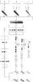
进行本系统的部署和实验,基于联想拯救者R9000P作为计算平台,搭载3070系显卡。基于Ubuntu操作系统进行开发,安装有显卡驱动、CUDA10.1、CUDNN、OpenCV、PCL、Eigen等,以pytorch为框架进行数据集标注与训练,以Clion、PyCharm等IDE进行调试训练。图12为工件点云可视化及参数修改界面图。图13为模拟实际焊接测试界面图,在该界面中判断起始点终点坐标和焊枪垂直度。图14为点云数据预处理流程示意图,其中对于点云数据进行半径滤波以及区域生长算法的处理,详见前文的点云预处理部分。图15为数据标注示意图,由于网络训练。图16为条焊识别实操示意图,其中竖线标记部分即为补焊位置,通过训练后的网络模型精确识别。图17为补焊测试实操示意图,对实际补焊位置通过焊枪进行处理。The deployment and experimentation of this system is based on the Lenovo Rescuer R9000P as the computing platform, equipped with a 3070 series graphics card. Developed based on the Ubuntu operating system, installed graphics card drivers, CUDA10.1, CUDNN, OpenCV, PCL, Eigen, etc., use pytorch as the framework for data set annotation and training, and use Clion, PyCharm and other IDEs for debugging and training. Figure 12 is the interface diagram of workpiece point cloud visualization and parameter modification. Fig. 13 is a diagram of the simulated actual welding test interface, in which the coordinates of the starting point and end point and the verticality of the welding torch are judged. Figure 14 is a schematic diagram of the preprocessing flow of point cloud data, in which radius filtering and region growing algorithm are performed on the point cloud data, as detailed in the previous part of point cloud preprocessing. Figure 15 is a schematic diagram of data labeling due to network training. Figure 16 is a schematic diagram of the actual operation of strip welding recognition, in which the part marked by the vertical line is the repair welding position, which is accurately recognized by the trained network model. Figure 17 is a schematic diagram of the actual operation of the repair welding test, and the actual repair welding position is processed by the welding torch.
以上所述仅为本发明的较佳实施方式,本发明的保护范围并不以上述实施方式为限,但凡本领域普通技术人员根据本发明所揭示内容所作的等效修饰或变化,皆应纳入权利要求书中记载的保护范围内。The above descriptions are only preferred embodiments of the present invention, and the scope of protection of the present invention is not limited to the above embodiments, but all equivalent modifications or changes made by those of ordinary skill in the art according to the disclosure of the present invention should be included within the scope of protection described in the claims.
Claims (8)
Priority Applications (1)
| Application Number | Priority Date | Filing Date | Title |
|---|---|---|---|
| CN202210994552.3ACN115330734A (en) | 2022-08-18 | 2022-08-18 | Automatic robot repair welding system based on three-dimensional target detection and point cloud defect completion |
Applications Claiming Priority (1)
| Application Number | Priority Date | Filing Date | Title |
|---|---|---|---|
| CN202210994552.3ACN115330734A (en) | 2022-08-18 | 2022-08-18 | Automatic robot repair welding system based on three-dimensional target detection and point cloud defect completion |
Publications (1)
| Publication Number | Publication Date |
|---|---|
| CN115330734Atrue CN115330734A (en) | 2022-11-11 |
Family
ID=83926833
Family Applications (1)
| Application Number | Title | Priority Date | Filing Date |
|---|---|---|---|
| CN202210994552.3APendingCN115330734A (en) | 2022-08-18 | 2022-08-18 | Automatic robot repair welding system based on three-dimensional target detection and point cloud defect completion |
Country Status (1)
| Country | Link |
|---|---|
| CN (1) | CN115330734A (en) |
Cited By (7)
| Publication number | Priority date | Publication date | Assignee | Title |
|---|---|---|---|---|
| CN116843753A (en)* | 2023-07-03 | 2023-10-03 | 重庆理工大学 | Robust 6D pose estimation method based on bidirectional matching and global attention network |
| CN116894907A (en)* | 2023-09-11 | 2023-10-17 | 菲特(天津)检测技术有限公司 | RGBD camera texture mapping optimization method and system |
| CN117047237A (en)* | 2023-10-11 | 2023-11-14 | 太原科技大学 | Intelligent flexible welding system and method for special-shaped parts |
| CN117218123A (en)* | 2023-11-09 | 2023-12-12 | 上海擎刚智能科技有限公司 | Cold-rolled strip steel wire flying equipment fault detection method and system based on point cloud |
| CN117408999A (en)* | 2023-12-13 | 2024-01-16 | 安格利(成都)仪器设备有限公司 | Method for automatically detecting corrosion pits of containers and pipelines by utilizing point cloud complement |
| TWI831552B (en)* | 2022-12-30 | 2024-02-01 | 鴻海精密工業股份有限公司 | Method for training image identification model, method for identifying depth of images and related devices |
| CN119313655A (en)* | 2024-12-16 | 2025-01-14 | 长春理工大学 | A fast detection method for three-dimensional defects of bonding wires based on images and point clouds |
Citations (5)
| Publication number | Priority date | Publication date | Assignee | Title |
|---|---|---|---|---|
| US20150283654A1 (en)* | 2012-11-28 | 2015-10-08 | Lufthansa Technik Ag | Method and device for repairing an aircraft and/or gas turbine component |
| CN110524582A (en)* | 2019-09-16 | 2019-12-03 | 西安中科光电精密工程有限公司 | A kind of flexibility welding robot workstation |
| CN111730245A (en)* | 2020-06-22 | 2020-10-02 | 共享智能铸造产业创新中心有限公司 | Welding system and casting defect repair welding method |
| CN114273826A (en)* | 2021-12-31 | 2022-04-05 | 南京欧睿三维科技有限公司 | Automatic identification method of welding position for large workpieces to be welded |
| WO2022091543A1 (en)* | 2020-10-28 | 2022-05-05 | パナソニックIpマネジメント株式会社 | Repair welding segment detection method and repair welding segment detection device |
- 2022
- 2022-08-18CNCN202210994552.3Apatent/CN115330734A/enactivePending
Patent Citations (5)
| Publication number | Priority date | Publication date | Assignee | Title |
|---|---|---|---|---|
| US20150283654A1 (en)* | 2012-11-28 | 2015-10-08 | Lufthansa Technik Ag | Method and device for repairing an aircraft and/or gas turbine component |
| CN110524582A (en)* | 2019-09-16 | 2019-12-03 | 西安中科光电精密工程有限公司 | A kind of flexibility welding robot workstation |
| CN111730245A (en)* | 2020-06-22 | 2020-10-02 | 共享智能铸造产业创新中心有限公司 | Welding system and casting defect repair welding method |
| WO2022091543A1 (en)* | 2020-10-28 | 2022-05-05 | パナソニックIpマネジメント株式会社 | Repair welding segment detection method and repair welding segment detection device |
| CN114273826A (en)* | 2021-12-31 | 2022-04-05 | 南京欧睿三维科技有限公司 | Automatic identification method of welding position for large workpieces to be welded |
Non-Patent Citations (1)
| Title |
|---|
| ZITIAN HUANG 等: "PF-Net: Point Fractal Network for 3D Point Cloud Completion", 2020 IEEE/CVF CONFERENCE ON COMPUTER VISION AND PATTERN RECOGNITION (CVPR), 5 August 2020 (2020-08-05)* |
Cited By (12)
| Publication number | Priority date | Publication date | Assignee | Title |
|---|---|---|---|---|
| TWI831552B (en)* | 2022-12-30 | 2024-02-01 | 鴻海精密工業股份有限公司 | Method for training image identification model, method for identifying depth of images and related devices |
| CN116843753A (en)* | 2023-07-03 | 2023-10-03 | 重庆理工大学 | Robust 6D pose estimation method based on bidirectional matching and global attention network |
| CN116894907A (en)* | 2023-09-11 | 2023-10-17 | 菲特(天津)检测技术有限公司 | RGBD camera texture mapping optimization method and system |
| CN116894907B (en)* | 2023-09-11 | 2023-11-21 | 菲特(天津)检测技术有限公司 | RGBD camera texture mapping optimization method and system |
| CN117047237A (en)* | 2023-10-11 | 2023-11-14 | 太原科技大学 | Intelligent flexible welding system and method for special-shaped parts |
| CN117047237B (en)* | 2023-10-11 | 2024-01-19 | 太原科技大学 | Intelligent flexible welding system and method for special-shaped parts |
| CN117218123A (en)* | 2023-11-09 | 2023-12-12 | 上海擎刚智能科技有限公司 | Cold-rolled strip steel wire flying equipment fault detection method and system based on point cloud |
| CN117218123B (en)* | 2023-11-09 | 2024-02-02 | 上海擎刚智能科技有限公司 | Cold-rolled strip steel wire flying equipment fault detection method and system based on point cloud |
| CN117408999A (en)* | 2023-12-13 | 2024-01-16 | 安格利(成都)仪器设备有限公司 | Method for automatically detecting corrosion pits of containers and pipelines by utilizing point cloud complement |
| CN117408999B (en)* | 2023-12-13 | 2024-02-20 | 安格利(成都)仪器设备有限公司 | Method for automatically detecting corrosion pits of containers and pipelines by utilizing point cloud complement |
| CN119313655A (en)* | 2024-12-16 | 2025-01-14 | 长春理工大学 | A fast detection method for three-dimensional defects of bonding wires based on images and point clouds |
| CN119313655B (en)* | 2024-12-16 | 2025-04-04 | 长春理工大学 | A fast detection method for three-dimensional defects of bonding wires based on images and point clouds |
Similar Documents
| Publication | Publication Date | Title |
|---|---|---|
| CN115330734A (en) | Automatic robot repair welding system based on three-dimensional target detection and point cloud defect completion | |
| Li et al. | An AR-assisted deep learning-based approach for automatic inspection of aviation connectors | |
| CN111563446B (en) | Human-machine interaction safety early warning and control method based on digital twin | |
| CN114952809B (en) | Workpiece recognition and pose detection method, system, and grasping control method of a robotic arm | |
| CN115816460B (en) | Mechanical arm grabbing method based on deep learning target detection and image segmentation | |
| CN111080693A (en) | Robot autonomous classification grabbing method based on YOLOv3 | |
| CN107194559A (en) | A kind of work stream recognition method based on Three dimensional convolution neutral net | |
| CN115439458A (en) | Industrial image defect target detection algorithm based on depth map attention | |
| CN114155610B (en) | Panel assembly key action identification method based on upper half body posture estimation | |
| CN110186375A (en) | Intelligent high-speed rail white body assemble welding feature detection device and detection method | |
| CN113240798B (en) | Intelligent detection and configuration method of material completeness based on digital twin and AR | |
| CN117274843B (en) | UAV front-end defect recognition method and system based on lightweight edge computing | |
| CN114170686A (en) | Elbow bending behavior detection method based on human body key points | |
| CN112530267B (en) | Intelligent mechanical arm teaching method based on computer vision and application | |
| CN115810188A (en) | Method and system for identifying three-dimensional pose of fruit on tree based on single two-dimensional image | |
| Hao et al. | [Retracted] Fast Recognition Method for Multiple Apple Targets in Complex Occlusion Environment Based on Improved YOLOv5 | |
| CN116912158A (en) | Workpiece quality inspection method, device, equipment and readable storage medium | |
| CN113420839B (en) | Semi-automatic labeling method and segmentation positioning system for stacking planar target objects | |
| CN115270399A (en) | An industrial robot attitude recognition method, device and storage medium | |
| CN114972948A (en) | Neural detection network-based identification and positioning method and system | |
| CN117381793A (en) | A vision system for intelligent material detection based on deep learning | |
| CN111738264A (en) | An intelligent collection method of display panel data of equipment room equipment | |
| CN115019202B (en) | A step-by-step grasping detection method for service-type mobile robotic arms | |
| CN116843615A (en) | Lead frame intelligent total inspection method based on flexible light path | |
| CN119048488B (en) | Steel pipe defect detection system and method based on image analysis |
Legal Events
| Date | Code | Title | Description |
|---|---|---|---|
| PB01 | Publication | ||
| PB01 | Publication | ||
| SE01 | Entry into force of request for substantive examination | ||
| SE01 | Entry into force of request for substantive examination |