CN115325034A - High-speed rolling bearing sealing structure with fluid self-pumping effect - Google Patents
High-speed rolling bearing sealing structure with fluid self-pumping effectDownload PDFInfo
- Publication number
- CN115325034A CN115325034ACN202210979334.2ACN202210979334ACN115325034ACN 115325034 ACN115325034 ACN 115325034ACN 202210979334 ACN202210979334 ACN 202210979334ACN 115325034 ACN115325034 ACN 115325034A
- Authority
- CN
- China
- Prior art keywords
- ring
- sealing
- groove
- inner ring
- bearing
- Prior art date
- Legal status (The legal status is an assumption and is not a legal conclusion. Google has not performed a legal analysis and makes no representation as to the accuracy of the status listed.)
- Granted
Links
- 238000007789sealingMethods0.000titleclaimsabstractdescription123
- 239000012530fluidSubstances0.000titleclaimsabstractdescription44
- 238000005096rolling processMethods0.000titleclaimsabstractdescription40
- 230000000694effectsEffects0.000titleclaimsabstractdescription34
- 238000005086pumpingMethods0.000titleclaimsabstractdescription31
- 229910000831SteelInorganic materials0.000claimsabstractdescription13
- 239000010959steelSubstances0.000claimsabstractdescription13
- 229920000459Nitrile rubberPolymers0.000claimsabstractdescription4
- 230000006837decompressionEffects0.000claimsdescription4
- 238000005452bendingMethods0.000abstract2
- 239000010687lubricating oilSubstances0.000description15
- 238000010586diagramMethods0.000description6
- 230000007423decreaseEffects0.000description5
- 238000000034methodMethods0.000description4
- 230000004888barrier functionEffects0.000description2
- 239000000428dustSubstances0.000description2
- 230000002706hydrostatic effectEffects0.000description2
- 230000008569processEffects0.000description2
- 230000000630rising effectEffects0.000description2
- 230000009471actionEffects0.000description1
- 230000003373anti-fouling effectEffects0.000description1
- 230000009286beneficial effectEffects0.000description1
- 238000005260corrosionMethods0.000description1
- 230000007797corrosionEffects0.000description1
- 238000004134energy conservationMethods0.000description1
- 238000005461lubricationMethods0.000description1
- 238000003754machiningMethods0.000description1
- 238000004519manufacturing processMethods0.000description1
- 230000004048modificationEffects0.000description1
- 238000012986modificationMethods0.000description1
- 230000009467reductionEffects0.000description1
- 230000004044responseEffects0.000description1
Images


Classifications
- F—MECHANICAL ENGINEERING; LIGHTING; HEATING; WEAPONS; BLASTING
- F16—ENGINEERING ELEMENTS AND UNITS; GENERAL MEASURES FOR PRODUCING AND MAINTAINING EFFECTIVE FUNCTIONING OF MACHINES OR INSTALLATIONS; THERMAL INSULATION IN GENERAL
- F16C—SHAFTS; FLEXIBLE SHAFTS; ELEMENTS OR CRANKSHAFT MECHANISMS; ROTARY BODIES OTHER THAN GEARING ELEMENTS; BEARINGS
- F16C33/00—Parts of bearings; Special methods for making bearings or parts thereof
- F16C33/72—Sealings
- F16C33/76—Sealings of ball or roller bearings
- F16C33/762—Sealings of ball or roller bearings by means of a fluid
- F—MECHANICAL ENGINEERING; LIGHTING; HEATING; WEAPONS; BLASTING
- F16—ENGINEERING ELEMENTS AND UNITS; GENERAL MEASURES FOR PRODUCING AND MAINTAINING EFFECTIVE FUNCTIONING OF MACHINES OR INSTALLATIONS; THERMAL INSULATION IN GENERAL
- F16C—SHAFTS; FLEXIBLE SHAFTS; ELEMENTS OR CRANKSHAFT MECHANISMS; ROTARY BODIES OTHER THAN GEARING ELEMENTS; BEARINGS
- F16C33/00—Parts of bearings; Special methods for making bearings or parts thereof
- F16C33/72—Sealings
- F16C33/76—Sealings of ball or roller bearings
- F16C33/78—Sealings of ball or roller bearings with a diaphragm, disc, or ring, with or without resilient members
- F16C33/7803—Sealings of ball or roller bearings with a diaphragm, disc, or ring, with or without resilient members suited for particular types of rolling bearings
- F16C33/7806—Sealings of ball or roller bearings with a diaphragm, disc, or ring, with or without resilient members suited for particular types of rolling bearings for spherical roller bearings
- F—MECHANICAL ENGINEERING; LIGHTING; HEATING; WEAPONS; BLASTING
- F16—ENGINEERING ELEMENTS AND UNITS; GENERAL MEASURES FOR PRODUCING AND MAINTAINING EFFECTIVE FUNCTIONING OF MACHINES OR INSTALLATIONS; THERMAL INSULATION IN GENERAL
- F16C—SHAFTS; FLEXIBLE SHAFTS; ELEMENTS OR CRANKSHAFT MECHANISMS; ROTARY BODIES OTHER THAN GEARING ELEMENTS; BEARINGS
- F16C33/00—Parts of bearings; Special methods for making bearings or parts thereof
- F16C33/72—Sealings
- F16C33/76—Sealings of ball or roller bearings
- F16C33/78—Sealings of ball or roller bearings with a diaphragm, disc, or ring, with or without resilient members
- F16C33/7816—Details of the sealing or parts thereof, e.g. geometry, material
- F16C33/782—Details of the sealing or parts thereof, e.g. geometry, material of the sealing region
- F16C33/7823—Details of the sealing or parts thereof, e.g. geometry, material of the sealing region of sealing lips
- F—MECHANICAL ENGINEERING; LIGHTING; HEATING; WEAPONS; BLASTING
- F16—ENGINEERING ELEMENTS AND UNITS; GENERAL MEASURES FOR PRODUCING AND MAINTAINING EFFECTIVE FUNCTIONING OF MACHINES OR INSTALLATIONS; THERMAL INSULATION IN GENERAL
- F16C—SHAFTS; FLEXIBLE SHAFTS; ELEMENTS OR CRANKSHAFT MECHANISMS; ROTARY BODIES OTHER THAN GEARING ELEMENTS; BEARINGS
- F16C33/00—Parts of bearings; Special methods for making bearings or parts thereof
- F16C33/72—Sealings
- F16C33/76—Sealings of ball or roller bearings
- F16C33/78—Sealings of ball or roller bearings with a diaphragm, disc, or ring, with or without resilient members
- F16C33/7816—Details of the sealing or parts thereof, e.g. geometry, material
- F16C33/782—Details of the sealing or parts thereof, e.g. geometry, material of the sealing region
- F16C33/7826—Details of the sealing or parts thereof, e.g. geometry, material of the sealing region of the opposing surface cooperating with the seal, e.g. a shoulder surface of a bearing ring
- F—MECHANICAL ENGINEERING; LIGHTING; HEATING; WEAPONS; BLASTING
- F16—ENGINEERING ELEMENTS AND UNITS; GENERAL MEASURES FOR PRODUCING AND MAINTAINING EFFECTIVE FUNCTIONING OF MACHINES OR INSTALLATIONS; THERMAL INSULATION IN GENERAL
- F16C—SHAFTS; FLEXIBLE SHAFTS; ELEMENTS OR CRANKSHAFT MECHANISMS; ROTARY BODIES OTHER THAN GEARING ELEMENTS; BEARINGS
- F16C37/00—Cooling of bearings
- F16C37/007—Cooling of bearings of rolling bearings
Landscapes
- Engineering & Computer Science (AREA)
- General Engineering & Computer Science (AREA)
- Mechanical Engineering (AREA)
- Rolling Contact Bearings (AREA)
Abstract
Translated fromChinese
Description
Translated fromChinese技术领域technical field
本发明涉及轴承密封技术领域,具体为一种具有流体自泵送效应的高速滚动轴承密封结构。The invention relates to the technical field of bearing sealing, in particular to a high-speed rolling bearing sealing structure with fluid self-pumping effect.
背景技术Background technique
滚动轴承是工业基础件,其运行的可靠性是保证航天航空、武器装备、精密机床等复杂机械系统极限工作能力、运转精度、稳定性和延长寿命的关键环节。目前,在一些应用密封轴承场合,轴承的密封失效严重影响了轴承的正常运转和使用寿命。Rolling bearings are basic industrial components, and their operational reliability is the key link to ensure the ultimate working capacity, operating accuracy, stability and extended life of complex mechanical systems such as aerospace, weaponry, and precision machine tools. At present, in some applications of sealed bearings, the failure of the bearing seal seriously affects the normal operation and service life of the bearing.
轴承的密封可分为自带密封和外加密封两类。所谓的自带密封就是把轴承本身制作成具有密封功能的零部件;外加密封就是在轴承外部设计具有各种形式的密封装置,这种密封方法又分为非接触式与接触式两种。Bearing seals can be divided into two types: built-in seals and external seals. The so-called built-in seal is to make the bearing itself into a component with sealing function; the external seal is to design various forms of sealing devices outside the bearing. This sealing method is divided into two types: non-contact and contact.
非接触式密封就是密封件与其相对运动的零件不接触,且有恰当空隙的密封。A non-contact seal is a seal in which the seal is not in contact with its relative moving parts and has an appropriate gap.
现有技术的非接触式轴承,其内圈的两侧处均开设有截面呈勾形的环槽,密封圈的唇部伸至环槽中,并与环槽的内壁之间形成间隙配合,从而避免了密封圈和内圈接触摩擦,同时具有一定的防尘、防污能力,如中国专利申请号CN202021755899.5公开的用于轴承的非接触式密封结构。但是,由于勾形环槽形状复杂,沟底面粗糙度和椭圆度很难控制,产生的加工误差较大;且在轴承高速运转时,密封圈的唇部可能发生摆动,容易导致环槽内壁与密封圈之间形成接触状态,从而产生较大的摩擦力矩,加速密封的失效。In the non-contact bearing of the prior art, ring grooves with a hook-shaped cross section are opened on both sides of the inner ring, and the lip of the sealing ring extends into the ring groove and forms a clearance fit with the inner wall of the ring groove. In this way, the contact friction between the sealing ring and the inner ring is avoided, and at the same time, it has certain dustproof and antifouling capabilities, such as the non-contact sealing structure for bearings disclosed in Chinese Patent Application No. CN202021755899.5. However, due to the complex shape of the hook-shaped ring groove, it is difficult to control the roughness and ellipticity of the bottom surface of the groove, resulting in large machining errors; and when the bearing is running at high speed, the lip of the sealing ring may swing, which is likely to cause the inner wall of the ring groove to be in contact with the A contact state is formed between the sealing rings, thereby generating a large frictional moment and accelerating the failure of the seal.
接触式密封就是密封件与其相对运动的零件相接触且没有空隙的密封。现有技术的接触式轴承,由于内圈与密封圈唇口间为过盈配合,这种结构具有一定的防尘、防污能力,密封性能好。如中国专利申请号CN201420172200.0公开的一种双密封轴承。但是,当轴承高速运转时,由于内圈与密封唇口直接接触,从而会造成轴承摩擦力矩增大,摩擦温升过高,润滑效果降低,密封件磨损加剧,从而导致密封失效,缩短轴承的使用寿命。A contact seal is a seal in which the seal is in contact with its relative moving parts without gaps. In the contact bearing of the prior art, since the inner ring and the lip of the sealing ring are in an interference fit, this structure has certain dust-proof and dirt-proof capabilities and good sealing performance. For example, a double-sealed bearing disclosed in Chinese patent application number CN201420172200.0. However, when the bearing runs at high speed, because the inner ring is in direct contact with the sealing lip, the friction torque of the bearing will increase, the friction temperature will rise too high, the lubrication effect will decrease, and the wear of the seal will increase, which will lead to seal failure and shorten the bearing life. service life.
发明内容Contents of the invention
本部分的目的在于概述本发明的实施方式的一些方面以及简要介绍一些较佳实施方式。在本部分以及本申请的说明书摘要和发明名称中可能会做些简化或省略以避免使本部分、说明书摘要和发明名称的目的模糊,而这种简化或省略不能用于限制本发明的范围。The purpose of this section is to outline some aspects of embodiments of the invention and to briefly describe some preferred embodiments. Some simplifications or omissions may be made in this section, as well as in the abstract and titles of this application, to avoid obscuring the purpose of this section, the abstract and titles, and such simplifications or omissions should not be used to limit the scope of the invention.
鉴于上述和/或现有的滚动轴承存在的问题,提出了本发明。In view of the above and/or problems existing in existing rolling bearings, the present invention is proposed.
因此,本发明的目的是提供一种具有流体自泵送效应的高速滚动轴承密封结构,将使得轴承在高速运转时,仍有良好的密封性能和低摩擦力矩的效应。Therefore, the object of the present invention is to provide a high-speed rolling bearing sealing structure with fluid self-pumping effect, which will enable the bearing to still have good sealing performance and low frictional torque effect when the bearing runs at high speed.
为解决上述技术问题,根据本发明的一个方面,本发明提供了如下技术方案:In order to solve the above technical problems, according to one aspect of the present invention, the present invention provides the following technical solutions:
一种具有流体自泵送效应的高速滚动轴承密封结构,其包括:A high-speed rolling bearing sealing structure with fluid self-pumping effect, comprising:
外圈;outer ring;
内圈,设置在所述外圈内部,所述内圈沿径向方向由外径处到内径依次具有多个绕轴承中心轴线均匀间隔设置的后弯型螺旋槽、密封坝和内圈密封槽,其中,相邻的两个后弯型螺旋槽之间的区域形成为密封堰,且后弯型螺旋槽的流体出口的朝向与内圈的转向相反;The inner ring is arranged inside the outer ring, and the inner ring has a plurality of back-curved spiral grooves, sealing dams and inner ring sealing grooves arranged at even intervals around the central axis of the bearing from the outer diameter to the inner diameter in the radial direction. , wherein the area between two adjacent back-curved spiral grooves is formed as a sealing weir, and the direction of the fluid outlet of the backward-curved spiral groove is opposite to that of the inner ring;
密封圈,与所述外圈和内圈的外侧边密封连接,所述密封圈包括丁腈橡胶外层和钢骨架内层,钢骨架内层上设置有与后弯型螺旋槽连通的集流环槽,且该集流环槽环绕轴承中心轴线延伸,所述钢骨架内层的环体内设置有若干个导流通道,每一导流通道的导流进口孔位于钢骨架内层端面的外径处,每一导流通道的导流出口孔位于集流环槽内,导流通道连通密封腔;The sealing ring is sealed and connected with the outer side of the outer ring and the inner ring. The sealing ring includes an outer layer of nitrile rubber and an inner layer of a steel skeleton. and the collecting ring groove extends around the central axis of the bearing. Several guide channels are arranged in the ring body of the inner layer of the steel skeleton, and the guide inlet hole of each guide channel is located at the end surface of the inner layer of the steel skeleton. At the outer diameter, the diversion outlet hole of each diversion channel is located in the collector ring groove, and the diversion channel is connected to the sealing chamber;
滚动体,均匀设置在外圈和内圈之间;The rolling elements are evenly arranged between the outer ring and the inner ring;
保持架,设置在所述滚动体的两侧,使滚动体外圈和内圈之间均匀分布。The cages are arranged on both sides of the rolling elements, so that the outer and inner rings of the rolling elements are evenly distributed.
作为本发明所述的一种具有流体自泵送效应的高速滚动轴承密封结构的一种优选方案,其中,所述后弯型螺旋槽具有两个沿周向设置的内侧面,其中一个内侧面为朝向后弯型螺旋槽的内部凸出的内凸侧面,另一个内侧面为朝向后弯型螺旋槽的外部凹陷的内凹侧面。As a preferred solution of the high-speed rolling bearing sealing structure with fluid self-pumping effect according to the present invention, the backward-curved spiral groove has two inner sides arranged along the circumference, and one of the inner sides is The inner convex side protrudes toward the inside of the back-curved spiral groove, and the other inner side is an inner concave side concave toward the outside of the back-bent spiral groove.
作为本发明所述的一种具有流体自泵送效应的高速滚动轴承密封结构的一种优选方案,其中,所述后弯型螺旋槽的两个内侧面槽壁型线均为螺旋线,且两个内侧槽壁型线的螺旋线具有相同的螺旋角。As a preferred solution of the high-speed rolling bearing sealing structure with fluid self-pumping effect described in the present invention, wherein, the groove wall profiles of the two inner sides of the backward-curved spiral groove are both helical lines, and the two The helices of the two inner groove wall profiles have the same helix angle.
作为本发明所述的一种具有流体自泵送效应的高速滚动轴承密封结构的一种优选方案,其中,所述集流环槽位于后弯型螺旋槽的径向内侧部。As a preferred solution of the high-speed rolling bearing sealing structure with fluid self-pumping effect according to the present invention, the collector ring groove is located at the radially inner side of the back-curved spiral groove.
作为本发明所述的一种具有流体自泵送效应的高速滚动轴承密封结构的一种优选方案,其中,所述密封圈与内圈连接的部位具有内唇,所述内圈具有内圈密封槽,所述内唇卡入至内圈密封槽内,且内唇与内圈密封槽间隙配合。As a preferred solution of the high-speed rolling bearing sealing structure with fluid self-pumping effect according to the present invention, the part where the sealing ring is connected to the inner ring has an inner lip, and the inner ring has an inner ring sealing groove , the inner lip snaps into the sealing groove of the inner ring, and the inner lip and the sealing groove of the inner ring are in clearance fit.
作为本发明所述的一种具有流体自泵送效应的高速滚动轴承密封结构的一种优选方案,其中,所述密封圈与外圈连接的部位具有外唇,所述外圈具有外圈密封槽,所述外唇卡入至外圈密封槽内,并且外唇与外圈密封槽间隙配合。As a preferred solution of a high-speed rolling bearing sealing structure with fluid self-pumping effect according to the present invention, the part where the sealing ring is connected to the outer ring has an outer lip, and the outer ring has an outer ring sealing groove , the outer lip snaps into the sealing groove of the outer ring, and the outer lip is in clearance fit with the sealing groove of the outer ring.
作为本发明所述的一种具有流体自泵送效应的高速滚动轴承密封结构的一种优选方案,其中,所述外唇设置匚形减压槽。As a preferred solution of the high-speed rolling bearing sealing structure with fluid self-pumping effect described in the present invention, the outer lip is provided with a U-shaped decompression groove.
与现有技术相比,本发明具有的有益效果是:Compared with prior art, the beneficial effect that the present invention has is:
1、润滑油由后弯型螺旋槽流入到密封腔内的过程中,根据能量守恒,由于后弯型螺旋槽流通截面的扩大,润滑油流动的相对速度减小,润滑油速度减小引发的动能差和后弯型螺旋槽对润滑油所做的功将转化为因牵连速度增加形成的动能和流体动压。后弯型螺旋槽中的流体静压和从槽根到外径处逐渐升高的动压形成推动内圈与密封圈相分离的开启力,从而降低了轴承高速运转时内圈和密封圈间的摩擦与温升,避免了密封圈的失效,进一步提高了轴承的使用寿命。1. During the process of lubricating oil flowing into the sealing chamber from the back-curved spiral groove, according to energy conservation, due to the expansion of the flow cross-section of the backward-curved spiral groove, the relative velocity of the lubricating oil flow decreases, and the lubricating oil velocity decreases. The kinetic energy difference and the work done by the back-bent spiral groove on the lubricating oil will be converted into kinetic energy and hydrodynamic pressure due to the increase of dragging speed. The hydrostatic pressure in the back-curved spiral groove and the dynamic pressure gradually rising from the root of the groove to the outer diameter form an opening force that pushes the inner ring and the sealing ring to separate, thereby reducing the gap between the inner ring and the sealing ring when the bearing is running at high speed. The friction and temperature rise of the bearing avoid the failure of the sealing ring and further improve the service life of the bearing.
2、从后弯型螺旋槽的槽根到出口处,压力逐渐升高的泵出流体与随内圈转动的流体膜剪切流构成的压力流体屏障,和密封坝阻力的共同作用下,使得密封腔中的润滑油难以泄漏到轴承外,从而实现了密封。2. From the groove root of the back-curved spiral groove to the outlet, the pressure fluid barrier formed by the gradually increasing pressure of the pumped fluid and the fluid film shear flow rotating with the inner ring, together with the resistance of the seal dam, makes the The lubricating oil in the seal chamber is difficult to leak out of the bearing, thereby achieving sealing.
3、密封圈内径唇口卡入内圈密封槽,且两者为间隙配合,其间隙量小,可阻碍外界灰尘等杂志进入的同时,减少润滑油泄漏。此外,两者的间隙配合极大程度上降低了摩擦磨损,提高了轴承的使用寿命,并且密封圈外唇设置的匚形减压槽可提高密封圈的抗压性和使用寿命。3. The lip of the inner diameter of the sealing ring is snapped into the sealing groove of the inner ring, and the two are clearance fit, and the clearance is small, which can prevent the entry of foreign dust and other magazines and reduce the leakage of lubricating oil. In addition, the clearance fit between the two greatly reduces friction and wear and improves the service life of the bearing, and the 匚-shaped decompression groove provided on the outer lip of the sealing ring can improve the pressure resistance and service life of the sealing ring.
附图说明Description of drawings
为了更清楚地说明本发明实施方式的技术方案,下面将将结合附图和详细实施方式对本发明进行详细说明,显而易见地,下面描述中的附图仅仅是本发明的一些实施方式,对于本领域普通技术人员来讲,在不付出创造性劳动性的前提下,还可以根据这些附图获得其它的附图。其中:In order to more clearly illustrate the technical solutions of the embodiments of the present invention, the present invention will be described in detail below in conjunction with the accompanying drawings and detailed embodiments. Obviously, the accompanying drawings in the following description are only some embodiments of the present invention. Ordinary technicians can also obtain other drawings based on these drawings without paying creative labor. in:
图1为本发明一种具有流体自泵送效应的高速滚动轴承密封结构的示意图;Fig. 1 is a schematic diagram of a high-speed rolling bearing sealing structure with fluid self-pumping effect according to the present invention;
图2为本发明一种具有流体自泵送效应的高速滚动轴承密封结构中密封圈的结构示意图;Fig. 2 is a structural schematic diagram of a sealing ring in a high-speed rolling bearing sealing structure with fluid self-pumping effect according to the present invention;
图3为本发明一种具有流体自泵送效应的高速滚动轴承密封结构中内圈的结构示意图;Fig. 3 is a structural schematic diagram of the inner ring in a high-speed rolling bearing sealing structure with fluid self-pumping effect according to the present invention;
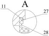
图4为本发明一种具有流体自泵送效应的高速滚动轴承密封结构图1的A部放大图;Fig. 4 is an enlarged view of part A of Fig. 1 of a high-speed rolling bearing sealing structure with fluid self-pumping effect according to the present invention;
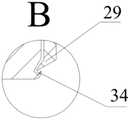
图5为本发明一种具有流体自泵送效应的高速滚动轴承密封结构图1的B部放大图;Fig. 5 is an enlarged view of part B of Fig. 1 of a high-speed rolling bearing sealing structure with fluid self-pumping effect according to the present invention;
图6为本发明一种具有流体自泵送效应的高速滚动轴承密封结构中内圈的立体图;Fig. 6 is a perspective view of the inner ring in a high-speed rolling bearing sealing structure with fluid self-pumping effect according to the present invention;
图7为本发明一种具有流体自泵送效应的高速滚动轴承密封结构密封圈的立体图。Fig. 7 is a perspective view of a high-speed rolling bearing sealing structure sealing ring with fluid self-pumping effect according to the present invention.
具体实施方式Detailed ways
为使本发明的上述目的、特征和优点能够更加明显易懂,下面结合附图对本发明的具体实施方式做详细的说明。In order to make the above objects, features and advantages of the present invention more comprehensible, specific implementations of the present invention will be described in detail below in conjunction with the accompanying drawings.
其次,本发明结合示意图进行详细描述,在详述本发明实施方式时,为便于说明,表示器件结构的剖面图会不依一般比例作局部放大,而且所述示意图只是示例,其在此不应限制本发明保护的范围。此外,在实际制作中应包含长度、宽度及深度的三维空间尺寸。Secondly, the present invention is described in detail in conjunction with schematic diagrams. When describing the implementation of the present invention in detail, for the convenience of explanation, the cross-sectional view showing the device structure will not be partially enlarged according to the general scale, and the schematic diagram is only an example, and it should not be limited here. The protection scope of the present invention. In addition, the three-dimensional space dimensions of length, width and depth should be included in actual production.
为使本发明的目的、技术方案和优点更加清楚,下面将结合附图对本发明的实施方式作进一步地详细描述。In order to make the purpose, technical solution and advantages of the present invention clearer, the following will further describe the implementation of the present invention in detail in conjunction with the accompanying drawings.
本发明提供一种具有流体自泵送效应的高速滚动轴承密封结构,将使得轴承在高速运转时,仍有良好的密封性能和低摩擦力矩的效应。The invention provides a high-speed rolling bearing sealing structure with fluid self-pumping effect, which can make the bearing still have good sealing performance and low frictional torque effect when running at high speed.
图1-图7示出的是本发明一种具有流体自泵送效应的高速滚动轴承密封结构一实施方式的结构示意图,请参阅图1-图7,本实施方式的一种具有流体自泵送效应的高速滚动轴承密封结构,其主体部分包括外圈1、内圈3、密封圈2、滚动体4和保持架5。Fig. 1-Fig. 7 shows a structural schematic diagram of an embodiment of a high-speed rolling bearing sealing structure with fluid self-pumping effect according to the present invention. Please refer to Fig. 1-Fig. The sealing structure of high-speed rolling bearing with high effect, its main part includes
外圈1为该具有流体自泵送效应的高速滚动轴承密封结构的外圈部件。The
内圈3设置在外圈1内部,且沿径向方向由外径处到内径依次具有多个绕轴承中心轴线均匀间隔设置的后弯型螺旋槽31、密封坝32和内圈密封槽34,其中,相邻的两个后弯型螺旋槽31之间的区域形成为密封堰33,且后弯型螺旋槽31的流体出口的朝向与内圈3的转向相反,后弯型螺旋槽31具有两个沿周向设置的内侧面,其中一个内侧面为朝向后弯型螺旋槽31的内部凸出的内凸侧面311,另一个内侧面为朝向后弯型螺旋槽31的外部凹陷的内凹侧面312,后弯型螺旋槽31的两个内侧面槽壁型线均为螺旋线,且两个内侧槽壁型线的螺旋线具有相同的螺旋角。The
密封圈2与外圈1和内圈3的外侧边密封连接,密封圈2包括丁腈橡胶外层21和钢骨架内层22,使其抗腐蚀和防振性能得到极大的提升,钢骨架内层22上设置有与后弯型螺旋槽31连通的集流环槽25,且该集流环槽25环绕轴承中心轴线延伸,钢骨架内层22的环体内设置有若干个导流通道23,每一导流通道23的导流进口孔24位于钢骨架内层22端面的外径处,每一导流通道23的导流出口孔26位于集流环槽25内,导流通道23连通密封腔,集流环槽25位于后弯型螺旋槽31的径向内侧部。The sealing
结合图1-图7,该种具有流体自泵送效应的高速滚动轴承密封结构在使用时,内圈3按图3中箭头方向旋转时,本发明的轴承密封结构为泵出式,后弯型螺旋槽31内润滑油做功,一方面提升了润滑油的压力,另一方面提高了润滑油的速度;在高速离心力作用下,润滑油沿槽面轮廓线切向向轴承外径侧流动而泵送出后弯型螺旋槽31,回到轴承密封腔中。润滑油在由后弯型螺旋槽31根部向外径处流动的过程中,牵连速度逐渐增大,后弯型螺旋槽31流通截面也在扩大,润滑油流动的相对速度逐渐减小;流体速度减小引发的动能差和后弯型螺旋槽31对润滑油所做的功将转化为因牵连速度增加形成的动能和流体动压,后弯型螺旋槽31中的流体静压和从槽根到外径处逐渐升高的动压构成了内圈3和密封圈2端面的开启力,从而降低了轴承高速运转时内圈3和密封圈2间的摩擦与温升,进一步提高了轴承的使用寿命。从后弯型螺旋槽31槽根到外径处压力逐渐升高的泵出流体与随动环转动的流体膜剪切流构成的压力流体屏障,以及密封坝32的阻力,使得密封腔中的流体难以泄漏至密封面内径侧而获得密封性,后弯型螺旋槽31根部的润滑油向外径侧泵送流出后,后弯型螺旋槽槽根处区域压力降低,由于压差作用,密封腔内的润滑油经过导流进口孔24、导流通道23和导流出口孔26被压入集流环槽25,再次流入后弯型螺旋槽31根部,再由后弯型螺旋槽31槽面做功加速成高速流体,在离心力作用下,沿工作面切向向内圈3外径侧流动而泵送至密封腔内,周而复始形成自泵送循环。1-7, when this kind of high-speed rolling bearing sealing structure with fluid self-pumping effect is in use, when the
在旋转工作状态,轴承自泵送密封结构具有动态响应能力,当密封系统受到扰动,密封间隙产生波动,密封间隙变小,端面流体膜压会显著变大,则导致开启力变大;密封间隙变大,端面流体膜压会显著变小,导致开启力变小,使密封间隙维持平衡。In the rotating working state, the self-pumping sealing structure of the bearing has dynamic response capability. When the sealing system is disturbed, the sealing gap will fluctuate, the sealing gap will become smaller, and the fluid film pressure on the end face will increase significantly, resulting in a larger opening force; the sealing gap If it becomes larger, the fluid film pressure on the end surface will be significantly reduced, resulting in a smaller opening force and maintaining the balance of the sealing gap.
进一步的,请同时参阅图1、4和5,密封圈2与内圈3连接的部位具有内唇29,内圈3具有内圈密封槽34,内唇29卡入至内圈密封槽34内,且内唇29与内圈密封槽34间隙配合,一方面可以防止内部润滑油的泄漏,从而提高密封性能,另一方面,可以使轴承内部与外部隔离,防止外部的杂物灰尘进入轴承内部;且两者的间隙配合极大程度上降低了摩擦磨损,提高了轴承的高速运行效率。密封圈2与外圈1连接的部位具有外唇27,外圈1具有外圈密封槽11,外唇27卡入至外圈密封槽11内,并且外唇27与外圈密封槽11间隙配合,通过与外圈密封槽11的轴向过盈来固定密封圈2,此外,密封圈外唇27设置了 匚形减压槽28,可提高密封圈的抗压性和使用寿命。Further, please refer to Figures 1, 4 and 5 at the same time, the part where the sealing
虽然在上文中已经参考实施方式对本发明进行了描述,然而在不脱离本发明的范围的情况下,可以对其进行各种改进并且可以用等效物替换其中的部件。尤其是,只要不存在结构冲突,本发明所披露的实施方式中的各项特征均可通过任意方式相互结合起来使用,在本说明书中未对这些组合的情况进行穷举性的描述仅仅是出于省略篇幅和节约资源的考虑。因此,本发明并不局限于文中公开的特定实施方式,而是包括落入权利要求的范围内的所有技术方案。While the invention has been described above with reference to the embodiments, various modifications may be made and equivalents may be substituted for elements thereof without departing from the scope of the invention. In particular, as long as there is no structural conflict, the various features in the embodiments disclosed in the present invention can be used in combination with each other in any way, and the description of these combinations is not exhaustive in this specification only to show In consideration of omitting space and saving resources. Therefore, the present invention is not limited to the specific embodiments disclosed herein, but includes all technical solutions falling within the scope of the claims.
Claims (7)
Translated fromChinesePriority Applications (1)
| Application Number | Priority Date | Filing Date | Title |
|---|---|---|---|
| CN202210979334.2ACN115325034B (en) | 2022-08-16 | 2022-08-16 | A high-speed rolling bearing sealing structure with fluid self-pumping effect |
Applications Claiming Priority (1)
| Application Number | Priority Date | Filing Date | Title |
|---|---|---|---|
| CN202210979334.2ACN115325034B (en) | 2022-08-16 | 2022-08-16 | A high-speed rolling bearing sealing structure with fluid self-pumping effect |
Publications (2)
| Publication Number | Publication Date |
|---|---|
| CN115325034Atrue CN115325034A (en) | 2022-11-11 |
| CN115325034B CN115325034B (en) | 2023-08-08 |
Family
ID=83923667
Family Applications (1)
| Application Number | Title | Priority Date | Filing Date |
|---|---|---|---|
| CN202210979334.2AActiveCN115325034B (en) | 2022-08-16 | 2022-08-16 | A high-speed rolling bearing sealing structure with fluid self-pumping effect |
Country Status (1)
| Country | Link |
|---|---|
| CN (1) | CN115325034B (en) |
Cited By (2)
| Publication number | Priority date | Publication date | Assignee | Title |
|---|---|---|---|---|
| CN115823109A (en)* | 2022-12-08 | 2023-03-21 | 哈尔滨轴承集团有限公司 | Deep groove ball bearing and bearing processing method |
| CN116123211A (en)* | 2023-02-22 | 2023-05-16 | 南京林业大学 | A high-speed rolling bearing with adaptive sealing and enhanced cooling structure |
Citations (8)
| Publication number | Priority date | Publication date | Assignee | Title |
|---|---|---|---|---|
| US5180173A (en)* | 1990-07-09 | 1993-01-19 | Ebara Corporation | Spiral groove face seal |
| US5201531A (en)* | 1992-04-02 | 1993-04-13 | John Crane Inc. | Face seal with double spiral grooves |
| CN1336497A (en)* | 2000-07-31 | 2002-02-20 | 希尔蒂股份公司 | Sealing of bearing |
| AU2001286896A1 (en)* | 2000-09-01 | 2002-03-13 | Upstate Biotechnology, Inc | A recombinant monoclonal antibody to phosphotyrosine-containing proteins |
| JP2003166548A (en)* | 2001-11-28 | 2003-06-13 | Koyo Seiko Co Ltd | Sealing device of rolling bearing |
| CN105736704A (en)* | 2014-12-11 | 2016-07-06 | 舍弗勒技术有限两合公司 | Lip-shaped oil seal and bearing |
| CN107654496A (en)* | 2017-05-24 | 2018-02-02 | 襄阳振本传动设备有限公司 | a supporting roller |
| CN112963543A (en)* | 2021-03-23 | 2021-06-15 | 南京林业大学 | Diffusion type self-pumping fluid dynamic and static pressure type mechanical seal |
- 2022
- 2022-08-16CNCN202210979334.2Apatent/CN115325034B/enactiveActive
Patent Citations (8)
| Publication number | Priority date | Publication date | Assignee | Title |
|---|---|---|---|---|
| US5180173A (en)* | 1990-07-09 | 1993-01-19 | Ebara Corporation | Spiral groove face seal |
| US5201531A (en)* | 1992-04-02 | 1993-04-13 | John Crane Inc. | Face seal with double spiral grooves |
| CN1336497A (en)* | 2000-07-31 | 2002-02-20 | 希尔蒂股份公司 | Sealing of bearing |
| AU2001286896A1 (en)* | 2000-09-01 | 2002-03-13 | Upstate Biotechnology, Inc | A recombinant monoclonal antibody to phosphotyrosine-containing proteins |
| JP2003166548A (en)* | 2001-11-28 | 2003-06-13 | Koyo Seiko Co Ltd | Sealing device of rolling bearing |
| CN105736704A (en)* | 2014-12-11 | 2016-07-06 | 舍弗勒技术有限两合公司 | Lip-shaped oil seal and bearing |
| CN107654496A (en)* | 2017-05-24 | 2018-02-02 | 襄阳振本传动设备有限公司 | a supporting roller |
| CN112963543A (en)* | 2021-03-23 | 2021-06-15 | 南京林业大学 | Diffusion type self-pumping fluid dynamic and static pressure type mechanical seal |
Non-Patent Citations (2)
| Title |
|---|
| 汪久根;陈芳华;陈李果;张勇强;: "螺旋槽轴承研究综述", 润滑与密封, no. 03* |
| 陈家庆, 刘录, 赵艳铃: "流体动压柔性径向密封技术的研究与应用", 石油化工高等学校学报, no. 01* |
Cited By (3)
| Publication number | Priority date | Publication date | Assignee | Title |
|---|---|---|---|---|
| CN115823109A (en)* | 2022-12-08 | 2023-03-21 | 哈尔滨轴承集团有限公司 | Deep groove ball bearing and bearing processing method |
| CN116123211A (en)* | 2023-02-22 | 2023-05-16 | 南京林业大学 | A high-speed rolling bearing with adaptive sealing and enhanced cooling structure |
| CN116123211B (en)* | 2023-02-22 | 2023-08-01 | 南京林业大学 | A high-speed rolling bearing with adaptive sealing and enhanced cooling structure |
Also Published As
| Publication number | Publication date |
|---|---|
| CN115325034B (en) | 2023-08-08 |
Similar Documents
| Publication | Publication Date | Title |
|---|---|---|
| CN115325034B (en) | A high-speed rolling bearing sealing structure with fluid self-pumping effect | |
| JP6305432B2 (en) | Sliding parts | |
| CN100402874C (en) | Thrust plain bearings | |
| CN106439023B (en) | A kind of cosine curve type mechanical seal end surface structure | |
| CN105465371A (en) | Bidirectional-rotation self-pumping fluid dynamic pressure type mechanical seal | |
| TW201704650A (en) | Mixed-type dynamic pressure gas radial bearing | |
| CN113090337A (en) | Reverse shaft sealing device for double-rotor aircraft engine | |
| CN101696728A (en) | Liquid lubricated end face seal structure with cross-scale surface texture characteristic | |
| CN102927287A (en) | Mechanical end face seal with combined fluid slot structure | |
| CN207892992U (en) | A kind of eccentric circular ring ramp type hydrostatic thrust bearing lubricating pad | |
| CN205025934U (en) | Quiet dynamic pressure main shaft | |
| CN205605823U (en) | Satisfy just direction changing imitative fin type groove terminal surface mechanical seal structure | |
| CN210510283U (en) | Reducer output shaft sealing device of shield construction electric locomotive | |
| CN203051777U (en) | Mechanical face seal with combination fluid type groove structure | |
| CN114857273B (en) | face seal assembly | |
| CN113236781B (en) | A sealing ring with anti-friction heat dissipation structure on the end surface and its processing method | |
| CN202188125U (en) | Spherical mechanical sealing device | |
| CN214578856U (en) | Mechanical sealing structure | |
| CN205618672U (en) | Two -way rotation is from pump sending fluid dynamic pressure type mechanical seal | |
| CN110410504B (en) | A mechanical seal end face structure with variable depth helical T-shaped groove | |
| CN212454254U (en) | Double W type combined metal sealing structure for roller cone bits | |
| CN102174963A (en) | Spherical mechanical sealing device | |
| CN207333698U (en) | Ternary distorts type groove end surface mechanical sealing structure | |
| CN116241569B (en) | A horizontal bearing sealing structure | |
| CN221145310U (en) | Liquid film mechanical sealing device for aero-engine rotating machinery |
Legal Events
| Date | Code | Title | Description |
|---|---|---|---|
| PB01 | Publication | ||
| PB01 | Publication | ||
| SE01 | Entry into force of request for substantive examination | ||
| SE01 | Entry into force of request for substantive examination | ||
| GR01 | Patent grant | ||
| GR01 | Patent grant |