CN115324179A - An underground sewage interception and discharge system with integrated functions of pumping and self-flow - Google Patents
An underground sewage interception and discharge system with integrated functions of pumping and self-flowDownload PDFInfo
- Publication number
- CN115324179A CN115324179ACN202211007877.4ACN202211007877ACN115324179ACN 115324179 ACN115324179 ACN 115324179ACN 202211007877 ACN202211007877 ACN 202211007877ACN 115324179 ACN115324179 ACN 115324179A
- Authority
- CN
- China
- Prior art keywords
- sewage
- wall
- drainage
- seepage
- pumping
- Prior art date
- Legal status (The legal status is an assumption and is not a legal conclusion. Google has not performed a legal analysis and makes no representation as to the accuracy of the status listed.)
- Granted
Links
Images


Classifications
- E—FIXED CONSTRUCTIONS
- E03—WATER SUPPLY; SEWERAGE
- E03F—SEWERS; CESSPOOLS
- E03F1/00—Methods, systems, or installations for draining-off sewage or storm water
- E03F1/002—Methods, systems, or installations for draining-off sewage or storm water with disposal into the ground, e.g. via dry wells
- E—FIXED CONSTRUCTIONS
- E03—WATER SUPPLY; SEWERAGE
- E03F—SEWERS; CESSPOOLS
- E03F5/00—Sewerage structures
- E03F5/04—Gullies inlets, road sinks, floor drains with or without odour seals or sediment traps
- E—FIXED CONSTRUCTIONS
- E03—WATER SUPPLY; SEWERAGE
- E03F—SEWERS; CESSPOOLS
- E03F5/00—Sewerage structures
- E03F5/10—Collecting-tanks; Equalising-tanks for regulating the run-off; Laying-up basins
- E03F5/101—Dedicated additional structures, interposed or parallel to the sewer system
- E—FIXED CONSTRUCTIONS
- E03—WATER SUPPLY; SEWERAGE
- E03F—SEWERS; CESSPOOLS
- E03F5/00—Sewerage structures
- E03F5/22—Adaptations of pumping plants for lifting sewage
Landscapes
- Health & Medical Sciences (AREA)
- Life Sciences & Earth Sciences (AREA)
- Engineering & Computer Science (AREA)
- Hydrology & Water Resources (AREA)
- Public Health (AREA)
- Water Supply & Treatment (AREA)
- Sewage (AREA)
Abstract
Description
Translated fromChinese技术领域technical field
本发明涉及地下污水截排技术领域,特别涉及一种具有泵抽及自流一体化功能的地下污水截排系统。The invention relates to the technical field of underground sewage interception and drainage, in particular to an underground sewage interception and drainage system with integrated functions of pumping and artesian flow.
背景技术Background technique
金属矿山尤其是露天开采为主的铜矿山,在进行开采的过程中需要剥离大量的表层土及废石,往自然的山沟进行堆放,从而形成排土场。由于占地面积大以及当时的环保要求,早期建设的排土场底部都没有进行防渗,而铜矿山排土场内的土石一般含硫化物和重金属比较高,长期暴露在空气中经氧化和雨水作用后会产生含重金属的酸性水往下渗,最终造成排土场下游地下水污染。近些年随着国家对环保的重视程度越来越高,尤其是对地下水的保护,陆续出台颁布了一系列相关的政策和法规,其中提出了要加强矿山地下水污染源头预防和风险管控,而矿山地下水污染源头主要就是排土场产生的污水,因此,为有效管控矿山地下水污染源头就需要对排土场下游的地下污水尽可能靠前进行拦截并导排至污水库集中收集与处理,以免造成排土场下游地下水污染扩散。Metal mines, especially copper mines, which are mainly open-pit mining, need to strip a large amount of topsoil and waste rock during the mining process, and stack them in natural ravines to form a dump. Due to the large area and the environmental protection requirements at that time, the bottom of the early construction of the dump was not anti-seepage, and the soil and rocks in the copper mine dump generally contain relatively high sulfide and heavy metals, and are oxidized after long-term exposure to the air. After interacting with rainwater, acidic water containing heavy metals will seep down, eventually causing groundwater pollution downstream of the dump. In recent years, as the country pays more and more attention to environmental protection, especially the protection of groundwater, a series of related policies and regulations have been promulgated, which propose to strengthen the source prevention and risk control of groundwater pollution in mines, and The main source of groundwater pollution in mines is the sewage generated by dumps. Therefore, in order to effectively control the source of groundwater pollution in mines, it is necessary to intercept the underground sewage downstream of the dump as far as possible and guide it to the sewage reservoir for centralized collection and treatment to avoid Caused the spread of groundwater pollution downstream of the dump.
目前矿山排土场下游的地下污水截排系统主要是通过在污水库下游设置垂直帷幕,并在垂直帷幕的内侧设置单个渗水井或井群采用泵抽将污水抽回上游的污水库,或在垂直帷幕的内侧设置截获墙和收集井同样采用泵抽将污水抽回上游的污水库,但这样做的缺点也比较明显:At present, the underground sewage interception and drainage system downstream of the mine dump is mainly set up a vertical curtain downstream of the sewage reservoir, and a single seepage well or well group is installed inside the vertical curtain to pump the sewage back to the upstream sewage reservoir, or The interception wall and collection wells are set on the inner side of the vertical curtain to pump the sewage back to the upstream sewage reservoir, but the disadvantages of this method are also obvious:
1、高度依赖抽排设施,一旦抽排设施出现故障或停电时就无法进行污水抽排,从而容易造成地下污水扩散;1. It is highly dependent on the drainage facilities. Once the drainage facilities fail or the power is cut off, the sewage cannot be pumped and discharged, which will easily cause the underground sewage to spread;
2、仅通过抽排设施来抽排污水,能耗高;2. The sewage is pumped and discharged only through the pumping and drainage facilities, which consumes a lot of energy;
3、地下污水的收集效率还有较大的提升空间。3. There is still room for improvement in the collection efficiency of underground sewage.
发明内容Contents of the invention
针对现有技术中存在的问题,本发明的目的在于提供一种具有泵抽及自流一体化功能的地下污水截排系统,该种截排系统结合对污水的泵抽及自流功能为一体,可选择采用泵抽或自流的方式来抽排污水,不再高度依赖抽排设施,并且泵抽和自流排污还可以同步进行,从而能够有效降低抽排设施的能耗,另外,截水墙和导渗沟形成三维立体式的收集系统,能够更加全面、快速、高效地实现对地下污水的收集。Aiming at the problems existing in the prior art, the object of the present invention is to provide an underground sewage interception and drainage system with the integrated function of pumping and self-flowing. Choose to use pumping or self-flowing methods to pump and drain sewage, no longer highly dependent on pumping and drainage facilities, and pumping and self-flowing sewage can be carried out simultaneously, which can effectively reduce the energy consumption of pumping and drainage facilities. In addition, cutoff walls and guides The seepage ditch forms a three-dimensional collection system, which can collect underground sewage more comprehensively, quickly and efficiently.
本发明的上述技术目的是通过以下技术方案得以实现的:一种具有泵抽及自流一体化功能的地下污水截排系统,设于排土场与污水库之间,包括拦渣坝,所述拦渣坝位于所述污水库的上游,为不透水的坝体;截水墙,所述截水墙位于所述拦渣坝的上游,为设于地面以下、底部两侧高中间低的地下墙体;导渗沟,所述导渗沟位于所述截水墙的上游,为地面以下挖成、连通所述排土场与所述截水墙的沟槽;集排井,所述集排井竖立设置于所述截水墙中间的低洼处,所述集排井的侧壁上开设有用于与所述截水墙连通的花孔,所述集排井内还设有污水泵,所述污水泵的输出端通过管道通向所述污水库;导排管,所述导排管一端连接在所述集排井上,另一端穿过所述拦渣坝并通向所述污水库。The above-mentioned technical purpose of the present invention is achieved through the following technical solutions: an underground sewage interception and drainage system with integrated functions of pumping and artesian flow, which is located between the dump site and the sewage reservoir, including a slag dam, the The dam is located upstream of the sewage reservoir, and is an impermeable dam; the cutoff wall, the cutoff wall is located upstream of the dam, and is located below the ground, with two sides of the bottom being high and the middle low. Wall; seepage ditch, the seepage ditch is located upstream of the cutoff wall, and is a groove dug below the ground to connect the dump site and the cutoff wall; collection and drainage well, the collection and drainage well It is erected at the low-lying place in the middle of the cut-off wall, and the side wall of the collection and drainage well is provided with a flower hole for communicating with the cut-off wall. A sewage pump is also provided in the collection and drainage well, and the sewage The output end of the pump leads to the sewage reservoir through the pipeline; the drainage pipe, one end of the drainage pipe is connected to the collection and drainage well, and the other end passes through the slag retaining dam and leads to the sewage reservoir.
在一些实施例中,所述拦渣坝的表面和所述污水库的库底铺设有相互连接成整体的防渗膜。In some embodiments, the surface of the dam and the bottom of the sewage reservoir are laid with an anti-seepage membrane connected to each other as a whole.
在一些实施例中,所述防渗膜远离所述污水库的一端埋设并锚固于所述拦渣坝的坝脚以下,所述防渗膜还在位于所述拦渣坝坝顶的位置处设有锚固点。In some embodiments, the end of the anti-seepage membrane away from the sewage reservoir is embedded and anchored below the dam foot of the dam, and the anti-seepage membrane is also located at the crest of the dam With anchor point.
在一些实施例中,所述导排管穿过所述拦渣坝的同时还穿过所述防渗膜,并在所述防渗膜上留有贯穿口,所述贯穿口与所述导排管的外壁之间通过套筒来进行密封连接。In some embodiments, the drainage pipe passes through the slag dam and also passes through the anti-seepage membrane, and a through hole is left on the anti-seepage membrane, and the through hole is connected with the guide pipe. The outer walls of the row pipes are sealed and connected through sleeves.
在一些实施例中,所述导排管出水口的标高高于所述污水库的溢洪道底板标高。In some embodiments, the elevation of the outlet of the drainage pipe is higher than the elevation of the floor of the spillway of the sewage reservoir.
在一些实施例中,所述截水墙由导水填料充填而成,所述导渗沟内也充填有所述导水填料。In some embodiments, the cutoff wall is filled with water-conducting fillers, and the seepage guide ditch is also filled with the water-conducting fillers.
在一些实施例中,所述截水墙和所述导渗沟的所述导水填料上均铺设有粘土。In some embodiments, clay is laid on the water-conducting filler of the cut-off wall and the seepage ditch.
在一些实施例中,所述导水填料通过反滤透水性土工材料完全包裹。In some embodiments, the water-conducting filler is completely wrapped by reverse filtration water-permeable geotechnical material.
在一些实施例中,所述导渗沟内的所述导水填料中埋设有导渗管,所述导渗管连通所述排土场与所述集排井,所述导渗管的侧壁上开设有花孔。In some embodiments, a seepage pipe is buried in the water-conducting filler in the seepage guide ditch, and the seepage guide pipe communicates with the dump site and the collection and drainage well, and the side wall of the seepage guide pipe There are flower holes on the top.
在一些实施例中,所述集排井的底部标高低于所述截水墙、顶部标高高于所述粘土。In some embodiments, the bottom elevation of the collection and drainage well is lower than the cutoff wall, and the top elevation is higher than the clay.
综上所述,本发明具有以下有益效果:In summary, the present invention has the following beneficial effects:
与现有技术相比,本发明提供的一种具有泵抽及自流一体化功能的地下污水截排系统,可通过导渗沟和截水墙来形成三维立体式的地下污水收集系统,使地下污水的收集效率得到显著的提升,且除配备常规的泵抽设施外还可通过自流方式将地下污水导排至下游污水库,可任选泵抽或自流来进行排污,当然还可同时进行泵抽和自流排污,这样不仅能耗低而且保证率也高,且整个系统不再高度依赖抽排设施,极大降低了地下污水向下游扩散的风险。Compared with the prior art, the present invention provides an underground sewage interception and drainage system with integrated functions of pumping and artesian flow, which can form a three-dimensional underground sewage collection system through seepage ditch and cutoff wall, so that underground sewage The collection efficiency has been significantly improved, and in addition to being equipped with conventional pumping facilities, underground sewage can also be guided to the downstream sewage reservoir by gravity, and pumping or gravity can be selected for sewage discharge, of course, pumping can also be carried out at the same time And self-flowing sewage, which not only has low energy consumption but also has a high guarantee rate, and the whole system is no longer highly dependent on pumping and drainage facilities, which greatly reduces the risk of underground sewage spreading downstream.
附图说明Description of drawings
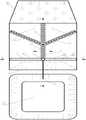
图1为本发明第一实施例中的具有泵抽及自流一体化功能的地下污水截排系统在矿山排土场下游中的俯视布局图;Fig. 1 is a top view layout diagram of the underground sewage interception and drainage system with integrated function of pumping and artesian flow in the downstream of the mine dump in the first embodiment of the present invention;
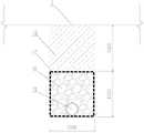
图2为沿图中A-A线的剖面图;Figure 2 is a sectional view along line A-A in the figure;
图3为沿图中B-B线的剖面图;Fig. 3 is a sectional view along the B-B line in the figure;
图4为沿图中C-C线的剖面图;Fig. 4 is a sectional view along line C-C in the figure;
图5为本发明第二实施例中的具有泵抽及自流一体化功能的地下污水截排系统在矿山排土场下游中的剖视布局图;Fig. 5 is the cross-sectional layout diagram of the underground sewage interception and drainage system with integrated function of pumping and artesian flow in the downstream of the mine dump in the second embodiment of the present invention;
图6为图5当中D-D线剖面图。FIG. 6 is a cross-sectional view along line D-D in FIG. 5 .
图中:1、拦渣坝;10、排土场;11、防渗膜;2、截水墙;20、污水库;3、导渗沟;30、导水填料;31、导渗管;4、集排井;40、反滤透水性土工材料;5、导排管;50、粘土;60、污水泵。In the figure: 1, slag dam; 10, dump site; 11, anti-seepage membrane; 2, cutoff wall; 20, sewage reservoir; 3, seepage ditch; 30, water-conducting filler; 31, seepage pipe; 4 , Collection and drainage well; 40, reverse filter water-permeable geotechnical material; 5, guide and drainage pipe; 50, clay; 60, sewage pump.
具体实施方式Detailed ways
为了便于理解本发明,下面将参照相关附图对本发明进行更全面的描述。附图中给出了本发明的若干实施例。但是,本发明可以以许多不同的形式来实现,并不限于本文所描述的实施例。相反地,提供这些实施例的目的是使对本发明的公开内容更加透彻全面。In order to facilitate the understanding of the present invention, the present invention will be described more fully below with reference to the associated drawings. Several embodiments of the invention are shown in the drawings. However, the present invention can be embodied in many different forms and is not limited to the embodiments described herein. Rather, these embodiments are provided so that the disclosure of the present invention will be thorough and complete.
需要说明的是,当元件被称为“固设于”另一个元件,它可以直接在另一个元件上或者也可以存在居中的元件。当一个元件被认为是“连接”另一个元件,它可以是直接连接到另一个元件或者可能同时存在居中元件。本文所使用的术语“上游”、“下游”、“底部”、“顶部”以及类似的表述只是为了说明的目的。It should be noted that when an element is referred to as being “fixed on” another element, it may be directly on the other element or there may be an intervening element. When an element is referred to as being "connected to" another element, it can be directly connected to the other element or intervening elements may also be present. The terms "upstream", "downstream", "bottom", "top" and similar expressions are used herein for the purpose of description only.
除非另有定义,本文所使用的所有的技术和科学术语与属于本发明的技术领域的技术人员通常理解的含义相同。本文中在本发明的说明书中所使用的术语只是为了描述具体的实施例的目的,不是旨在于限制本发明。本文所使用的术语“及/或”包括一个或多个相关的所列项目的任意的和所有的组合。Unless otherwise defined, all technical and scientific terms used herein have the same meaning as commonly understood by one of ordinary skill in the technical field of the invention. The terms used herein in the description of the present invention are for the purpose of describing specific embodiments only, and are not intended to limit the present invention. As used herein, the term "and/or" includes any and all combinations of one or more of the associated listed items.
实施例1Example 1
图1至图4所示为本发明实施例1中的具有泵抽及自流一体化功能的地下污水截排系统,本实施例为拦渣坝1上游没有淤积库容、已淤满从排土场10上流下来的泥沙及石渣、即将要进行封场绿化的情况(如图2所示),本实施例中,截排系统设于排土场10与污水库20之间,用于拦截及导排矿山排土场10下游的地下污水,包括拦渣坝1、截水墙2、导渗沟3、集排井4以及导排管5。Figures 1 to 4 show the underground sewage interception and drainage system with integrated functions of pumping and artesian flow in
如图2所示,拦渣坝1位于污水库20的上游,采用粘性土筑坝而成,为不透水、用于拦渣及阻水的坝体,为了防渗,可在拦渣坝1的表面和污水库20的库底铺设有相互连接成整体的防渗膜11,防渗膜11可选用2.0mm厚的HDPE土工膜,为了对防渗膜11进行锚固,可将防渗膜11远离污水库20的一端(即防渗膜11位于拦渣坝1上游坡面坝底的一端)埋设并锚固于拦渣坝1的坝脚以下并低于集排井4底部以下至少1m,优选为1m,以实现更充分的防渗,同时减少开挖工程量,还可在防渗膜11位于拦渣坝1坝顶的位置处设置锚固点。As shown in Figure 2, the
如图1-4所示,截水墙2位于拦渣坝1的上游,本实施例优选截水墙2平行于拦渣坝1的坝轴线设置,为设于地面以下、底部两侧高中间低、用于拦截地下污水的条形地下墙体,截水墙2底部两侧形成的坡度为2%,截水墙2的厚度为0.6~1m,本实施例优选为0.8m,深度为3~5m,本实施例优选为4m,截水墙2在垂直距离拦渣坝1上游坝脚3m的位置处进行布置,截水墙2从上至下依次由压实的粘土50层和导水填料30层充填而成,其中粘土50层厚1m并与地面标高齐平,压实度为0.9,粘土50层用于阻隔地表水进入截水墙2内,减少了地下污水产生量同时,还减轻了截排系统的负担,导水填料30层厚3m,导水填料30可由粒径为20~50mm的碎石构成,其被反滤透水性土工材料40包裹起来,本实施例优选为200g/m2的无纺土工布,以起到反滤作用,防止细颗粒带入截水墙或盲沟内造成淤堵,影响导排污水效果。As shown in Figures 1-4, the
如图1、图2以及图4所示,导渗沟3位于截水墙2的上游,为地面以下挖成、沿纵坡坡向连通排土场10与截水墙2、用于收集及导排地下渗水的线形沟槽,导渗沟3的纵向坡度为2%,本实施例中的导渗沟3设有三条,三条导渗沟3在向截水墙2方向导排的路径中逐渐汇合成一条,整体呈三叉状或者“鱼刺”状排布(如图1所示),导渗沟3的宽度为0.6~1m,本实施例中优选为1m,导渗沟3的深度为1~2m,本实施例中优选为2m,导渗沟3内从上至下依次为压实的粘土50和填充的导水填料30,其中粘土50层和导水填料30层的厚度均为1m,粘土50层压实度为0.9并与地面标高齐平,粘土50层用于阻隔地表水进入导渗沟3内,减少地下污水产生量同时,还减轻了截排系统的负担,导水填料30可由粒径为20~50mm的碎石构成,其被反滤透水性土工材料40包裹起来,本实施例优选为200g/m2的无纺土工布,以起到反滤作用,防止细颗粒带入截水墙或盲沟内造成淤堵,影响导排污水效果,为了加快污水导排,可在导渗沟3内的导水填料30中埋设有导渗管31,并将导渗管31连通排土场10与集排井4,导渗管31可选用DN200~DN315的HDPE管,本实施例优选为DN315的HDPE管,并在导渗管31的侧壁上开设有花孔,该花孔孔径为6mm~10mm,优选为10mm(如图2和图4所示),导渗管31与集排井4最好采用密封性好的焊接来进行连接,焊接前需在集排井4上开设焊接孔,焊接孔的开孔孔径选定为315mm,该尺寸与导渗管31的管径一致即可。As shown in Fig. 1, Fig. 2 and Fig. 4, the
为了使截水墙2中聚集的污水能够自然流入至集排井4中,需将集排井4竖立设置于截水墙2中间的低洼处,并在集排井4的侧壁上开设用于与截水墙2连通的花孔,并且花孔的分布位置与导水填料30层所在的位置重合,花孔最好呈梅花型布置,花孔的孔径为10~16mm,优选为16mm,集排井4是用于集水及导排的竖向管井,其可采用管径为DN630~DN1000的HDPE管,优选为DN630的HDPE管,为了安全和避免自然雨水流入集排井4内,集排井4配备有带锁的井盖,集排井4的底部还设有具有液位控制功能的具有自动启停功能的污水泵60,并且最好要求选用的污水泵60具有耐酸耐腐蚀的性能,污水泵60的输出端上连接有管道,管道从集排井4内伸出并通向污水库20,集排井4的底部标高低于截水墙2、顶部标高高于粘土50,具体的,集排井4地面以下深度为4~8m,露出地面的顶部标高不小于0.5m,底部标高低于截水墙2底部最低点不小于1m,而作为本实施例中的优选方案,集排井4的整体高度为6m,其中地面以下深度为5m,露出地面1m,底部标高低于截水墙2底部最低点1m(如图3所示),如此设置让集排井4的井底始终低于截水墙2底部最低点的标高,使截水墙2中的污水能够更加彻底地随着重力渗流并汇集在集排井4内,以免污水在截水墙2中因无法及时排走而大量聚集,另外集排井4的顶部高于地面设置能够避免地表雨水流入集排井4中,由于本系统主要在于对地下污水的处理,如果地表雨水也进入本系统的话,不但增加污水量,而且给本系统的工作带来额外负担,因此需要将集排井4的顶部高于地面设置,以避免地表雨水流入集排井4中。In order to allow the sewage accumulated in the
如图1和图2所示,集排井4上还连接有导排管5,导排管5可采用管径为DN200~DN400的HDPE管,其管身不开孔,纵向坡度不小于1%,在本实施例中,导排管5可采用DN315的HDPE管,其纵向坡度可设为2%,集排井4和导排管5最好采用密封性好的焊接来进行连接,焊接前需在集排井4上开设焊接孔,焊接孔的开孔孔径选定为315mm,该尺寸与导排管5的管径一致即可,导排管5可埋设于粘土50层中,导排管5一端连接在集排井4上,另一端穿过拦渣坝1并通向污水库20,导排管5穿过拦渣坝1的同时还穿过防渗膜11,并在防渗膜11上留有贯穿口,贯穿口与导排管5的外壁之间可通过套筒来进行密封连接,即在导排管5上套设套筒,通过套筒与防渗膜11之间的热焊,来实现密封连接,套筒可采用2.0mm厚的HDPE材质制作而成,且为了避免污水倒灌,要让导排管5出水口的标高高于污水库20的溢洪道底板标高。As shown in Figure 1 and Figure 2, the drainage pipe 5 is also connected to the collection and drainage well 4, and the drainage pipe 5 can be a HDPE pipe with a pipe diameter of DN200-DN400. %, in the present embodiment, the HDPE pipe of DN315 can be used for the drainage pipe 5, and its longitudinal gradient can be set as 2%. Need to offer welding hole on the collecting and discharging well 4 before, the opening aperture of welding hole is selected as 315mm, this size is consistent with the pipe diameter of guiding pipe 5 and gets final product, and guiding pipe 5 can be buried in
通过以上技术方案,上游排土场10渗入地下的污水在多条导渗沟3的导流以及汇流的作用下,被逐渐引流导向至截水墙2,其中导渗沟3能够将地下污水快速导走,避免污水进一步向深处渗透,从而起到预先截排的作用,导渗沟3中的导渗管31则提供了一条高速导流通道,能够将污水直接导入至集排井4中,起到了进一步加速污水截排的作用,导渗沟3是水平向线性收集,截水墙2是竖向面的收集,二者共同构成三维立体式的地下污水收集截排系统,污水渗入截水墙2内之后,在重力的作用下将逐渐汇集至集排井4中,此时可通过污水泵60来将集排井4内的污水抽送至污水库20,也可随着集排井4内水位的升高,通过导排管5以自流的方式来将污水排送至污水库20,与现有技术相比,本系统可通过导渗沟3和截水墙2来形成三维立体式的地下污水收集系统,使地下污水的收集效率得到显著的提升,且除配备常规的泵抽设施外还可通过自流方式将地下污水导排至下游污水库20,可任选泵抽或自流来进行排污,当然还可同时进行泵抽和自流排污,这样不仅能耗低而且保证率也高,且整个系统不再高度依赖抽排设施,极大降低了地下污水向下游扩散的风险。Through the above technical solutions, the sewage infiltrated into the ground from the
实施例2Example 2
图5和图6所示为本发明实施例2中的具有泵抽及自流一体化功能的地下污水截排系统,本实施例为拦渣坝1上游留有淤积库容、尚未淤满从排土场10上流下来的泥沙及石渣、将来淤满后再进行封场绿化的情况(如图5所示),本实施例与实施例1不同之处在于,本实施例中截水墙2和导渗沟3的导水填料30上均不铺设粘土50,本实施例中,并未在拦渣坝1的上游铺设大量粘土50,为从排土场10上流下来的泥沙及石渣提供了充足的淤积空间同时,能够快速将排土场10与拦渣坝1之间产生的地表污水收集,以免这些泥沙及石渣随着雨水四处流动而超出本污水截排系统的有效作用范围。Fig. 5 and Fig. 6 show the underground sewage intercepting and discharging system with pumping and artesian integration functions in
需要指出的是,本发明实施例2所提供的装置,其实现原理及产生的一些技术效果和第一实施例相同,为简要描述,本实施例未提及之处,可参考第一实施例中相应内容。It should be pointed out that the realization principle and some technical effects of the device provided by
以上所述实施例仅表达了本发明的几种实施方式,其描述较为具体和详细,但并不能因此而理解为对本发明专利范围的限制。应当指出的是,对于本领域的普通技术人员来说,在不脱离本发明构思的前提下,还可以做出若干变形和改进,这些都属于本发明的保护范围。因此,本发明专利的保护范围应以所附权利要求为准。The above-mentioned embodiments only express several implementation modes of the present invention, and the descriptions thereof are relatively specific and detailed, but should not be construed as limiting the patent scope of the present invention. It should be pointed out that those skilled in the art can make several modifications and improvements without departing from the concept of the present invention, and these all belong to the protection scope of the present invention. Therefore, the protection scope of the patent for the present invention should be based on the appended claims.
Claims (6)
Translated fromChinesePriority Applications (1)
| Application Number | Priority Date | Filing Date | Title |
|---|---|---|---|
| CN202211007877.4ACN115324179B (en) | 2022-08-22 | 2022-08-22 | Underground sewage interception and drainage system with functions of pumping and self-flowing |
Applications Claiming Priority (1)
| Application Number | Priority Date | Filing Date | Title |
|---|---|---|---|
| CN202211007877.4ACN115324179B (en) | 2022-08-22 | 2022-08-22 | Underground sewage interception and drainage system with functions of pumping and self-flowing |
Publications (2)
| Publication Number | Publication Date |
|---|---|
| CN115324179Atrue CN115324179A (en) | 2022-11-11 |
| CN115324179B CN115324179B (en) | 2025-07-22 |
Family
ID=83925983
Family Applications (1)
| Application Number | Title | Priority Date | Filing Date |
|---|---|---|---|
| CN202211007877.4AActiveCN115324179B (en) | 2022-08-22 | 2022-08-22 | Underground sewage interception and drainage system with functions of pumping and self-flowing |
Country Status (1)
| Country | Link |
|---|---|
| CN (1) | CN115324179B (en) |
Citations (5)
| Publication number | Priority date | Publication date | Assignee | Title |
|---|---|---|---|---|
| US5487621A (en)* | 1992-06-18 | 1996-01-30 | Hitachi, Ltd. | Large-depth underground drainage facility and method of running same |
| CN108687096A (en)* | 2018-04-03 | 2018-10-23 | 中国瑞林工程技术有限公司 | A kind of underground sewage collects interception system and its construction method |
| CN214940797U (en)* | 2021-03-04 | 2021-11-30 | 中国市政工程中南设计研究总院有限公司 | Pit type refuse landfill leachate drainage system |
| CN215288226U (en)* | 2021-06-18 | 2021-12-24 | 生态环境部华南环境科学研究所 | System for repairing underground water pollution through interception ditch |
| CN218861699U (en)* | 2022-08-22 | 2023-04-14 | 瑞林环境科技有限公司 | An underground sewage interception and drainage system with integrated functions of pumping and self-flowing |
- 2022
- 2022-08-22CNCN202211007877.4Apatent/CN115324179B/enactiveActive
Patent Citations (5)
| Publication number | Priority date | Publication date | Assignee | Title |
|---|---|---|---|---|
| US5487621A (en)* | 1992-06-18 | 1996-01-30 | Hitachi, Ltd. | Large-depth underground drainage facility and method of running same |
| CN108687096A (en)* | 2018-04-03 | 2018-10-23 | 中国瑞林工程技术有限公司 | A kind of underground sewage collects interception system and its construction method |
| CN214940797U (en)* | 2021-03-04 | 2021-11-30 | 中国市政工程中南设计研究总院有限公司 | Pit type refuse landfill leachate drainage system |
| CN215288226U (en)* | 2021-06-18 | 2021-12-24 | 生态环境部华南环境科学研究所 | System for repairing underground water pollution through interception ditch |
| CN218861699U (en)* | 2022-08-22 | 2023-04-14 | 瑞林环境科技有限公司 | An underground sewage interception and drainage system with integrated functions of pumping and self-flowing |
Also Published As
| Publication number | Publication date |
|---|---|
| CN115324179B (en) | 2025-07-22 |
Similar Documents
| Publication | Publication Date | Title |
|---|---|---|
| CN104131575B (en) | A kind of karst height grows the leak stopping water discharge method of the stratum dam foundation | |
| CN210066791U (en) | A precipitation combined system that is used for foundation ditch pressure release precipitation and dredges precipitation | |
| CN114718101B (en) | A seepage cut-off structure of a tailings pond with a seepage cut-off wall and a precipitation well and a construction method thereof | |
| CN101148885B (en) | Stereo drainage system structure for landfill underground water | |
| CN106087953B (en) | A kind of drainage and construction method for preventing and treating mountain area large size spoil ground mud-rock flow | |
| CN213867863U (en) | General industrial solid waste storage and disposal site structure based on abandoned mine | |
| CN103953008A (en) | Modified mixed dam applicable to tailings ponds | |
| CN113356322A (en) | Water drainage preventing system of valley type waste slag yard | |
| CN101148886B (en) | Drainage treatment structure for unbuilt or abuilding landfill slope underground water | |
| CN102383408B (en) | Greening method for high water level impermeable saline and alkaline lands and greening system | |
| CN218861699U (en) | An underground sewage interception and drainage system with integrated functions of pumping and self-flowing | |
| CN102535491A (en) | Embedded water permeable plate water collection siphon drainage method for side slope ground water interception | |
| CN206245444U (en) | Rainwater penetration system | |
| CN107816113A (en) | The Hills runoff that a kind of sewer pipe cellar for storing things combines harvests system and harvests method | |
| CN114277906B (en) | Drainage system and construction method for pit slope residual water | |
| CN111636408A (en) | A system and method for maintaining smooth drainage of ground fill in gullies | |
| CN203603127U (en) | Check valve type drainage system for underground water in channel | |
| CN112095742A (en) | A landfill leachate drainage system | |
| CN116516898B (en) | A high groundwater excavation channel slope drainage system and construction method | |
| CN208201898U (en) | One kind being used for highway excavation section subgrade drainage system | |
| CN115324179A (en) | An underground sewage interception and discharge system with integrated functions of pumping and self-flow | |
| CN207553248U (en) | The Hills runoff that a kind of sewer pipe cellar for storing things combines harvests system | |
| CN215367189U (en) | A blind ditch structure for water filtering suitable for rockfill dam foundation in mine waste rock yard | |
| RU2751569C1 (en) | Horizontal combined intake structure | |
| CN215165753U (en) | Toe board low reaches foundation ditch ponding positive pump drainage facility |
Legal Events
| Date | Code | Title | Description |
|---|---|---|---|
| PB01 | Publication | ||
| PB01 | Publication | ||
| SE01 | Entry into force of request for substantive examination | ||
| SE01 | Entry into force of request for substantive examination | ||
| GR01 | Patent grant | ||
| GR01 | Patent grant |