CN115316914A - Bendable structures, flexible instruments and endoscopes - Google Patents
Bendable structures, flexible instruments and endoscopesDownload PDFInfo
- Publication number
- CN115316914A CN115316914ACN202210938055.1ACN202210938055ACN115316914ACN 115316914 ACN115316914 ACN 115316914ACN 202210938055 ACN202210938055 ACN 202210938055ACN 115316914 ACN115316914 ACN 115316914A
- Authority
- CN
- China
- Prior art keywords
- bendable structure
- ring piece
- bendable
- ring
- joint
- Prior art date
- Legal status (The legal status is an assumption and is not a legal conclusion. Google has not performed a legal analysis and makes no representation as to the accuracy of the status listed.)
- Pending
Links
Images


Classifications
- A—HUMAN NECESSITIES
- A61—MEDICAL OR VETERINARY SCIENCE; HYGIENE
- A61B—DIAGNOSIS; SURGERY; IDENTIFICATION
- A61B1/00—Instruments for performing medical examinations of the interior of cavities or tubes of the body by visual or photographical inspection, e.g. endoscopes; Illuminating arrangements therefor
- A61B1/005—Flexible endoscopes
- A61B1/008—Articulations
- A—HUMAN NECESSITIES
- A61—MEDICAL OR VETERINARY SCIENCE; HYGIENE
- A61B—DIAGNOSIS; SURGERY; IDENTIFICATION
- A61B17/00—Surgical instruments, devices or methods
- A61B17/00234—Surgical instruments, devices or methods for minimally invasive surgery
Landscapes
- Health & Medical Sciences (AREA)
- Life Sciences & Earth Sciences (AREA)
- Surgery (AREA)
- Engineering & Computer Science (AREA)
- General Health & Medical Sciences (AREA)
- Nuclear Medicine, Radiotherapy & Molecular Imaging (AREA)
- Veterinary Medicine (AREA)
- Public Health (AREA)
- Animal Behavior & Ethology (AREA)
- Molecular Biology (AREA)
- Medical Informatics (AREA)
- Biomedical Technology (AREA)
- Heart & Thoracic Surgery (AREA)
- Physics & Mathematics (AREA)
- Radiology & Medical Imaging (AREA)
- Biophysics (AREA)
- Pathology (AREA)
- Optics & Photonics (AREA)
- Rehabilitation Therapy (AREA)
- Instruments For Viewing The Inside Of Hollow Bodies (AREA)
Abstract
Description
Translated fromChinese技术领域technical field
本发明涉及医疗器械领域,特别涉及一种可弯曲结构、柔性器械及内窥镜。The invention relates to the field of medical instruments, in particular to a bendable structure, a flexible instrument and an endoscope.
背景技术Background technique
内窥镜是常用的医疗器械,是现代医学诊疗中常用的检测仪器,可以经口腔进入胃内或经其他天然孔道进入体内,还可以经手术做的小切口进入人体内。医生可以借助内窥镜看到X射线不能显示的病变,对诊断病情非常有用。现有的内窥镜在进行头部弯曲转向时,需要利用自带的可弯曲结构进行控制。目前的可弯曲结构通常为蛇骨结构,但是目前的蛇骨结构容易在弯曲处断裂,而且结构十分复杂,导致加工和装配过程也变得复杂,生产成本增加。Endoscope is a commonly used medical device and a detection instrument commonly used in modern medical diagnosis and treatment. It can enter the stomach through the mouth or enter the body through other natural channels, and can also enter the human body through a small incision made by surgery. Doctors can use the endoscope to see lesions that X-rays cannot show, which is very useful for diagnosing the disease. The existing endoscope needs to use its own bendable structure to control when the head is bent and turned. The current bendable structure is usually a snake-bone structure, but the current snake-bone structure is easy to break at the bend, and the structure is very complicated, which leads to complicated processing and assembly processes and increased production costs.
发明内容Contents of the invention
本发明的目的在于提供一种可弯曲结构、柔性器械及内窥镜,以解决现有技术中柔性器械所使用的可弯曲结构存在容易断裂、结构复杂、生产成本高等问题。The object of the present invention is to provide a bendable structure, a flexible instrument and an endoscope, so as to solve the problems of easy breakage, complex structure and high production cost in the bendable structure used in flexible instruments in the prior art.
本发明提供了一种可弯曲结构,其包括接头,所述接头包括两个环片。每个所述环片设有至少两个相对的凸起部和至少两个相对的凹陷部。所述凸起部和所述凹陷部沿所述环片周向间隔设置。所述凸起部和所述凹陷部分别沿所述环片轴向的不同方向凸出。所述凸起部和所述凹陷部之间通过曲面连接。所述接头中的两个所述环片通过所述凸起部或所述凹陷部进行连接。如此设置时,既可以确保可弯曲结构的弯曲性能,又使得可弯曲结构在弯曲过程中不容易断裂,而且结构简单,便于加工和装配。The present invention provides a bendable structure comprising a joint comprising two ring pieces. Each of the ring pieces is provided with at least two opposite protrusions and at least two opposite depressions. The protrusions and the recesses are arranged at intervals along the circumferential direction of the ring piece. The protruding portion and the concave portion respectively protrude in different directions along the axial direction of the ring piece. The convex part and the concave part are connected by a curved surface. The two ring pieces in the joint are connected through the protrusion or the depression. When set in this way, the bending performance of the bendable structure can be ensured, and the bendable structure is not easily broken during the bending process, and the structure is simple, which is convenient for processing and assembly.
在一实施方式中,所述接头中的两个所述环片在所述可弯曲结构的轴向上镜像对称布置,以降低生产成本,而且可弯曲结构受力更均匀,弯曲效果更好。In one embodiment, the two ring pieces in the joint are arranged mirror-symmetrically in the axial direction of the bendable structure, so as to reduce production costs, and the bendable structure is more evenly stressed and has a better bending effect.
在一实施方式中,所述环片的环宽为所述环片的厚度的5倍~10倍,使环片在具有足够的弯曲强度的同时,还能兼顾其形变性能,同时也可以防止可弯曲结构的尺寸过大而影响其通过性。In one embodiment, the ring width of the ring piece is 5 to 10 times the thickness of the ring piece, so that the ring piece can not only have sufficient bending strength, but also take into account its deformation performance, and can also prevent The size of the bendable structure is too large to affect its passability.
在一实施方式中,所述环片的厚度不超过0.3mm,以确保环片具有较好的变形性能。In one embodiment, the thickness of the ring piece is not more than 0.3mm, so as to ensure that the ring piece has better deformation performance.
在一实施方式中,所述环片具有偶数个所述凸起部,所述凹陷部的数量与所述凸起部的数量一致。由于控制可弯曲结构的牵引体的数量多为偶数,故而凸起部和凹陷部也设置为偶数个。In one embodiment, the ring piece has an even number of the protrusions, and the number of the depressions is the same as the number of the protrusions. Since the number of the traction bodies controlling the bendable structure is mostly an even number, the number of protrusions and depressions is also set to an even number.
在一实施方式中,所述可弯曲结构由多个所述接头在所述可弯曲结构的轴向上依次连接而成,以使可弯曲结构能够实现更大角度的弯曲。In one embodiment, the bendable structure is formed by sequentially connecting a plurality of joints in the axial direction of the bendable structure, so that the bendable structure can be bent at a larger angle.
在一实施方式中,所述可弯曲结构在轴向上的柔度不相同,以便更精确的控制定位柔性器械的头部结构,还能使柔性器械适用于不同的使用场景。In one embodiment, the flexibility of the bendable structure in the axial direction is different, so as to control and position the head structure of the flexible device more precisely, and also make the flexible device suitable for different usage scenarios.
在一实施方式中,多个所述接头的柔度在所述可弯曲结构的轴向上从远端至近端逐渐减小,使可弯曲结构的远端的柔度最大而容易弯曲变形来适应于迂曲部位或狭窄部位。In one embodiment, the flexibility of the plurality of joints gradually decreases from the distal end to the proximal end in the axial direction of the bendable structure, so that the flexibility of the distal end of the bendable structure is maximized and easily deformed by bending. Suitable for tortuous parts or narrow parts.
在一实施方式中,多个所述环片在所述可弯曲结构的轴向上依次焊接连接,以便通过调整焊接力来控制可弯曲结构在轴向上的柔度。In one embodiment, the plurality of ring pieces are sequentially welded and connected in the axial direction of the bendable structure, so as to control the flexibility of the bendable structure in the axial direction by adjusting the welding force.
本发明还提供了一种柔性器械,其包括主体以及任一项所述的可弯曲结构,所述主体的远端设置所述可弯曲结构。The present invention also provides a flexible instrument, which includes a main body and any one of the bendable structures, and the distal end of the main body is provided with the bendable structure.
在一实施方式中,所述柔性器械还包括定位套,所述定位套包覆在所述可弯曲结构上,以通过定位套定位可弯曲结构,还可减少可弯曲结构在穿越腔道时对目标组织造成损伤。In one embodiment, the flexible instrument further includes a positioning sleeve, the positioning sleeve covers the bendable structure, so as to position the bendable structure through the positioning sleeve, and also reduce the impact of the bendable structure when passing through the cavity. Target tissue damage.
在一实施方式中,所述柔性器械还包括牵引件,所述牵引件的远端与所述可弯曲结构的远端固定连接,所述牵引件的近端依次穿过所有所述环片,使可弯曲结构在牵引件的控制下弯曲。In one embodiment, the flexible instrument further includes a traction member, the distal end of the traction member is fixedly connected to the distal end of the bendable structure, and the proximal end of the traction member passes through all the ring pieces sequentially, The bendable structure is caused to bend under the control of the tractor.
本发明还提供了一种内窥镜,其采用任一项所述的柔性器械。The present invention also provides an endoscope, which adopts any one of the flexible instruments.
与现有技术相比,本发明的可弯曲结构包括接头,所述接头包括两个环片,每个所述环片设有至少两个相对的凸起部和至少两个相对的凹陷部,所述凸起部和所述凹陷部沿所述环片周向间隔设置,所述凸起部和所述凹陷部分别沿所述环片轴向的不同方向凸出,所述凸起部和所述凹陷部之间通过曲面连接,所述接头中的两个所述环片通过所述凸起部或所述凹陷部进行连接。由于环片自身具有可变形的特性,而且凸起部和凹陷部之间的曲面还能够带来更大的变形量,因此,通过两个环片来构造接头时,可使接头很好地形变弯曲,确保可弯曲结构的弯曲性能。此外,由于使用了环片结构,使得接头还具有宽板的特性,使可弯曲结构在弯曲过程中不容易断裂,尤其各接头间的接触面积也大,即便多次弯曲,也不容易断裂,保证了整个可弯曲结构的结构强度,可靠性好,而且接头的结构简单,简化了加工和装配过程,降低了生产成本。本发明的可弯曲结构中的环片可以冲压一体成行,加工成本更低。Compared with the prior art, the bendable structure of the present invention includes a joint comprising two ring pieces, each of which is provided with at least two opposite protrusions and at least two opposite depressions, The protrusions and the depressions are arranged at intervals along the circumferential direction of the ring piece, the protrusions and the depressions respectively protrude in different directions along the axial direction of the ring piece, and the protrusions and The concave parts are connected by a curved surface, and the two ring pieces in the joint are connected by the convex part or the concave part. Since the ring piece itself has deformable characteristics, and the curved surface between the convex part and the concave part can also bring about a greater amount of deformation, when the joint is constructed by two ring pieces, the joint can be deformed well Bending, ensuring the bending performance of the bendable structure. In addition, due to the use of the ring structure, the joints also have the characteristics of wide plates, so that the bendable structure is not easy to break during the bending process, especially the contact area between the joints is also large, even if it is bent many times, it is not easy to break. The structure strength and reliability of the whole bendable structure are guaranteed, and the structure of the joint is simple, which simplifies the processing and assembly process and reduces the production cost. The ring pieces in the bendable structure of the present invention can be stamped into a row, and the processing cost is lower.
附图说明Description of drawings
本发明的实施方法以及相关实施例的特征、性质和优势将通过结合下列附图进行描述,其中:Embodiments of the invention and features, properties and advantages of related embodiments will be described with reference to the following drawings, in which:
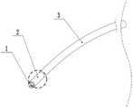
图1为本发明实施例的内窥镜的整体结构示意图;Fig. 1 is the overall structure schematic diagram of the endoscope of the embodiment of the present invention;
图2为本发明实施例的可弯曲结构的整体弯曲结构示意图;Fig. 2 is a schematic diagram of the overall bending structure of the bendable structure of the embodiment of the present invention;
图3为本发明实施例的可弯曲结构的整体弯曲侧视图;Fig. 3 is an overall curved side view of the bendable structure of the embodiment of the present invention;
图4和图5分别为本发明实施例的可弯曲结构的整体初始状态正视图和剖视图;Figure 4 and Figure 5 are the front view and cross-sectional view of the overall initial state of the bendable structure of the embodiment of the present invention, respectively;
图6为本发明实施例的远端连接件的俯视图;Fig. 6 is a top view of the distal connector of the embodiment of the present invention;
图7为本发明实施例的环片的整体立体结构示意图;7 is a schematic diagram of the overall three-dimensional structure of the ring piece in the embodiment of the present invention;
图8为本发明实施例的具有两个凸起部和两个凹陷部的环片正视图;Fig. 8 is a front view of a ring piece with two protrusions and two depressions according to an embodiment of the present invention;
图9为本发明实施例的具有两个凸起部和两个凹陷部的环片俯视图;Fig. 9 is a top view of a ring piece having two protrusions and two depressions according to an embodiment of the present invention;
图10为本发明实施例的一个接头的正视图;Fig. 10 is the front view of a joint of the embodiment of the present invention;
图11为本发明实施例的一个接头的弯曲状态正视图;Figure 11 is a front view of a joint in a bent state according to an embodiment of the present invention;
图12为本发明实施例的具有四个凸起部和四个凹陷部的环片正视图;Fig. 12 is a front view of a ring piece with four protrusions and four depressions according to an embodiment of the present invention;
图13为本发明实施例的具有四个凸起部和四个凹陷部的环片俯视图;Fig. 13 is a top view of a ring piece with four protrusions and four depressions according to an embodiment of the present invention;
图14为本发明实施例的多个接头依次连接形成可弯曲结构的初始状态正视图;Fig. 14 is a front view of an initial state in which a plurality of joints are sequentially connected to form a bendable structure according to an embodiment of the present invention;
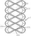
图15为本发明实施例的多个接头依次连接形成可弯曲结构的弯曲示意图;Fig. 15 is a schematic diagram of the bending of multiple joints connected in sequence to form a bendable structure according to the embodiment of the present invention;
图16为本发明实施例的在可弯曲结构的外部包覆定位套的剖视图。Fig. 16 is a cross-sectional view of a positioning sleeve coated on the outside of a bendable structure according to an embodiment of the present invention.
具体实施方式Detailed ways
为使本发明的目的、优点和特征更加清楚,以下结合附图对本发明作进一步详细说明。需说明的是,附图均采用简化的形式且未按比例绘制,仅用以方便、明晰地辅助说明本发明实施例的目的。In order to make the purpose, advantages and features of the present invention clearer, the present invention will be further described in detail below in conjunction with the accompanying drawings. It should be noted that the drawings are all in simplified form and not drawn to scale, and are only used to facilitate and clearly assist the purpose of illustrating the embodiments of the present invention.
如在本说明书中所使用的,“一个”或者“一”等类似词语也不表示数量限制,而是表示存在至少一个;“多个”表示两个及两个以上的数量;“若干”的含义是数量不作限定。如在本说明书中所使用的,术语“或”通常是以包括“和/或”的含义而进行使用的,除非内容另外明确指出外。另外,在下文的描述中,给出了大量具体的细节以便提供对本发明更为彻底的理解。然而,对于本领域技术人员而言显而易见的是,本发明可以无需一个或多个这些细节而得以实施。在其他的例子中,为了避免与本发明发生混淆,对于本领域公知的一些技术特征未进行描述。在以下说明中,为了便于描述,使用了“轴向”、“周向”,还使用了“近端”及“远端”;“轴向”参照的是可弯曲结构或柔性器械的轴线方向;“周向”参照的是围绕可弯曲结构或柔性器械的轴线方向;“近端”参照的是靠近操作者方向;“远端”参照的是靠近患者方向。As used in this specification, "a" or "one" and other similar words do not mean quantitative limitation, but mean that there is at least one; "plurality" means two or more than two; "several" The meaning is that the quantity is not limited. As used in this specification, the term "or" is generally employed in its sense including "and/or" unless the content clearly dictates otherwise. Additionally, in the following description, numerous specific details are given in order to provide a more thorough understanding of the present invention. It will be apparent, however, to one skilled in the art that the present invention may be practiced without one or more of these details. In other examples, some technical features known in the art are not described in order to avoid confusion with the present invention. In the following description, for the convenience of description, "axial" and "circumferential" are used, and "proximal" and "distal" are also used; "axial" refers to the direction of the axis of the bendable structure or flexible instrument ; "circumferential" refers to the direction around the axis of the bendable structure or flexible instrument; "proximal" refers to the direction close to the operator; "distal" refers to the direction close to the patient.
本发明的核心在于提供一种可弯曲结构,包括接头,所述接头包括两个环片。每个所述环片设有至少两个相对的凸起部和至少两个相对的凹陷部。所述凸起部和所述凹陷部沿所述环片周向间隔设置。所述凸起部和所述凹陷部分别沿所述环片轴向的不同方向凸出。所述凸起部和所述凹陷部之间通过曲面连接。所述接头中的两个所述环片通过所述凸起部或所述凹陷部进行连接。The core of the present invention is to provide a bendable structure including a joint comprising two ring pieces. Each of the ring pieces is provided with at least two opposite protrusions and at least two opposite depressions. The protrusions and the recesses are arranged at intervals along the circumferential direction of the ring piece. The protruding portion and the concave portion respectively protrude in different directions along the axial direction of the ring piece. The convex part and the concave part are connected by a curved surface. The two ring pieces in the joint are connected through the protrusion or the depression.
本发明对可弯曲结构中接头的数量不作特殊要求。可弯曲结构中的接头的数量应根据实际需求来设定,一般的,接头的数量越多,弯曲角度越大。The present invention does not impose special requirements on the number of joints in the bendable structure. The number of joints in the bendable structure should be set according to actual needs. Generally, the greater the number of joints, the greater the bending angle.
本发明所涉及的可弯曲结构采用厚板宽、短板高的环片来组成接头,这种结构在确保接头可弯曲的同时,因其环片的厚板宽而不易断裂,且环片也容易加工成型,无需复杂的加工和装配过程,适合批量生产。The bendable structure involved in the present invention uses a ring piece with a thick plate width and a short plate height to form a joint. This structure ensures that the joint can be bent, but it is not easy to break because of the thick plate width of the ring piece, and the ring piece is also It is easy to process and shape without complex processing and assembly processes, and is suitable for mass production.
本发明所涉及的可弯曲结构主要应用于柔性器械以控制柔性器械末端的弯曲,可以实现任意角度的转动。The bendable structure involved in the present invention is mainly applied to flexible instruments to control the bending of the ends of the flexible instruments, and can realize rotation at any angle.
本发明所涉及的柔性器械包括主体和可弯曲结构。所述可弯曲结构设置在所述主体的远端。柔性器械还可包括牵引体,所述牵引件的远端与所述可弯曲结构的远端固定连接,所述牵引件的近端依次穿过所有所述环片。The flexible instrument involved in the present invention includes a main body and a bendable structure. The bendable structure is disposed at the distal end of the body. The flexible instrument may further include a traction body, the distal end of the traction element is fixedly connected to the distal end of the bendable structure, and the proximal end of the traction element passes through all the ring pieces sequentially.
本发明所涉及的柔性器械可以应用在内窥镜上,也可以应用在其他执行手术操作的医疗器械上。本发明所涉及的柔性器械可以是一次性使用产品或重复多次使用产品。The flexible instrument involved in the present invention can be applied to an endoscope, and can also be applied to other medical instruments for performing surgical operations. The flexible device involved in the present invention may be a single-use product or a multiple-use product.
以下结合附图以及优选实施例对本申请作进一步的说明,且在不冲突的情况下,下述的实施方式及实施方式中的特征可以相互补充或相互组合。以下描述中,以为内窥镜为示意进行说明,但该应用不作为对本发明的限定,本领域技术人员应当能够修改以下描述而得到除内窥镜外的其他柔性器械。The present application will be further described below in conjunction with the accompanying drawings and preferred embodiments, and the following implementations and features in the implementations can complement each other or be combined without conflict. In the following description, an endoscope is used as an illustration for illustration, but this application is not regarded as a limitation of the present invention. Those skilled in the art should be able to modify the following description to obtain other flexible instruments except endoscopes.
参考图1至图3,本发明实施例提供一种内窥镜,作为一种柔性器械使用,内窥镜从远端至近端在轴向上包括依次连接的头部结构1(可称之为先端部)、可弯曲结构2和主体3。头部结构1携带有摄像模组,可以实现体内环境的图像监测。可弯曲结构2带动头部结构1进行弯曲,以精确定位需要拍摄的目标位置。主体3为中空管状,便于推送整个内窥镜,实现内窥镜在人体内的操作。Referring to Fig. 1 to Fig. 3, the embodiment of the present invention provides an endoscope, which is used as a flexible instrument, and the endoscope includes sequentially connected head structures 1 (which can be referred to as is the tip), the
可弯曲结构2包括至少一个可弹性变形的接头21,优选为至少三个接头21,使弯曲结构2通过接头21而实现弯曲。以多个接头21为示意,可弯曲结构2可以做到360度全方向的弯曲和摆动。可弯曲结构2也可理解为蛇骨结构,本申请中,可弯曲结构2利用接头21本身的弹性变形来实现弯曲。可弯曲结构2具有初始状态和弯曲状态;在初始状态时,可弯曲结构2未发生弯曲,即图4和图5所示。The
如图4和图5所示,可弯曲结构2在牵引件4的控制下弯曲。牵引件4的远端与可弯曲结构2的远端固定连接,牵引件4的近端与内窥镜近端的控制部件连接,由控制部件驱动牵引件4运动。通过拉动其中一根牵引件4,即可实现向对应的方向的转动,通过两根或以上的牵引件4的控制,即可实现任意角度的转动控制。牵引件4穿过所有接头21后,穿出可弯曲结构2的近端。牵引件4与可弯曲结构2的远端优选以焊接的形式进行连接。牵引件4的远端可以与接头21直接连接,也可以与接头21间接地连接。牵引件4诸如为:丝、绳、条或带等,一般采用弹性丝。As shown in FIGS. 4 and 5 , the
作为一具体实施例,可弯曲结构2还可包括设置在最远端的远端连接件22,牵引件4的远端与远端连接件22固定连接。如图6所示,远端连接件22可以是一个环形结构,其环面与牵引件4的远端固定,优选焊接固定,如在远端连接件22的环面上形成4个焊接点221,焊接点221一般错开90°布置,也即,牵引件4一般以90度均布的四根形式出现。远端连接件22的结构可与环片211的结构相同或不相同。头部结构1可以直接安装在远端连接件22上。进一步地,可以在可弯曲结构2的近端设置近端连接件,近端连接件直接与主体3的远端连接。近端连接件的结构可与环片211的结构相同或不相同。As a specific embodiment, the
参考图7和图8,并结合图4和图5,接头21包括两个环片211在可弯曲结构2的轴向上叠置而成。所谓“叠置”指的是环片211在可弯曲结构2的轴向上堆叠且两者固定连接。每个环片211设有至少两个相对的凸起部211a和至少两个相对的凹陷部211b。凸起部211a和凹陷部211b沿环片21周向间隔设置。凸起部211a和凹陷部211b分别沿环片21轴向的不同方向凸出。凸起部211a和凹陷部211b之间通过曲面211c连接。优选地,凸起部211a和凹陷部211b之间通过光滑的曲面211c进行连接,也可以理解为,凸起部211a和凹陷部211b之间为曲率连续的自由的曲面211c,曲率连续限制了凸起部211a和曲面211c之间为光滑过渡,也限制了凹陷部211b和曲面211c之间为光滑过渡,减小应力集中。Referring to FIG. 7 and FIG. 8 , combined with FIG. 4 and FIG. 5 , the joint 21 includes two
环片211优选一次冲压成型。环片211在加工成型时,大多数需要弯曲加工,若弯曲部分的曲率半径很小,则这些部分会产生很大的应力,因此,为避免弯曲部分产生较大的应力,使弯曲部分的弯曲半径至少是环片211的厚度的5倍。在加工过程中,应根据使用性能要求,对环片211进行热处理,确保其硬度,如硬度可以为36~52HRC,降低其断裂风险。环片211自身由弹性材料制成,如金属材料或非金属材料均可。环片211的材料例如可以选用磷青铜、锡青铜、65Mn、55i2Mn、60Si2MnA、55SiMnVB、55SiMnMoV、60CrMn、60CrMnB、302、316等牌号的扁钢带。环片211的材料例如为弹性较好的塑料,如ABS等。环片211自身为对称结构,可以正反翻转使用,不存在误装配的可能。The
实际使用时,接头21中的两个环片211通过凸起部211a进行连接,而且凸起部211a与凸起部211a之间直接连接,也即,一个环片21中的所有凸起部211a与另一个环片21中的所有凸起部211a直接连接,或者是,接头21中的两个环片211通过凹陷部211b进行连接,而且凹陷部211b与凹陷部211b之间直接连接,即,一个环片21中的所有凹陷部211b与另一个环片21中的所有凹陷部211b直接连接。在本申请实施例中,接头21中的两个环片211之间以及接头21之间无需额外的零件进行连接,装配过程简单。In actual use, the two
因此,借助于环片211自身可弹性变形的特性,可使接头21很好地形变弯曲,确保可弯曲结构2的弯曲性能。并且环片211具有厚宽板的特性,在弯曲过程中不容易断裂,尤其各接头21间的接触面积也大,即便多次弯曲,也不容易断裂,保证了整个可弯曲结构2的结构强度,可靠性好。而且接头21的加工和装配容易实现,降低了生产成本。尤其环片211可以冲压一体成行,加工成本更低。本申请的可弯曲结构2的机械稳定性好,运动可控,可确保运动控制精度。Therefore, by means of the elastically deformable property of the
环片211上的所有凸起部211a是在同一个平面内分布,所有凹陷部211b也是在同一个平面内分布,确保运动的可控性,降低控制难度。All the
参阅图7~图9,环片211具有较厚的环宽W(即板宽),以及具有较小的板厚H(即板高)。优选地,环片211的环宽W为环片211的厚度H的5倍~10倍,使环片211在具有足够的弯曲强度的同时,还能兼顾其形变性能,同时也可以防止可弯曲结构2的尺寸过大而影响其通过性。进一步地,环片211的厚度H不超过0.3mm,以保证其具有较好的变形性能。因此,环片211的结构符合柔性材料原有属性,容易变形弯曲,并且因其环宽W较大而不易断裂,并且也容易加工成型,适合批量生产。还需理解,环片211可以弹性变形,且凸起部211a和凹陷部211b之间的曲面211c的刚性低于凸起部211a和凹陷部211b,因此,受力时,曲面211c的形变范围较大,保证了环片211的可形变性能。Referring to FIGS. 7-9 , the
本申请实施例中,可弯曲结构2通常由多个接头21在可弯曲结构2的轴向上依次连接而成,以使可弯曲结构2能够实现更大角度的弯曲。任意相邻两个接头21之间直接通过凸起部211a或凹陷部211b进行连接,一般焊接固定为优。In the embodiment of the present application, the
如图4和图5及图7和图8所示,作为一具体实施例,环片211具有两个凸起部211a和两个凹陷部211b,接头21中的一个环片211的两个凹陷部211b与另一个环片211的两个凹陷部211b直接焊接固定。可以理解,两个环片211翻转180°进行布置形成一个接头21。此时,相邻两个接头21可以通过环片211之间的凸起部211a直接焊接固定,以形成稳定的机械结构。As shown in Figure 4 and Figure 5 and Figure 7 and Figure 8, as a specific embodiment, the
如图12至图15所示,作为另一具体实施例,环片211具有四个凸起部211a和四个凹陷部211b,接头21中的一个环片211的四个凹陷部211b与另一个环片211的四个凹陷部211b直接焊接固定,此时,相邻两个接头21可以通过环片211之间的四个凸起部211a直接焊接固定。As shown in Figures 12 to 15, as another specific embodiment, the
接头21中的两个环片211在可弯曲结构2的轴向上可以镜像对称布置,也可以非镜像对称设置。优选地,接头21中的两个环片211在可弯曲结构2的轴向上镜像对称布置,此时,所有环片211的结构都相同,生产成本低,而且受力更均匀,弯曲效果更好。The two
牵引件4的远端与可弯曲结构2的远端固定后,牵引件4的近端依次穿过各个接头21后与控制部件连接。牵引件4穿过各个环片211对应凸起部211a或凹陷部211b的位置;如果接头21中的两个环片21之间通过凹陷部211b连接,则牵引件4穿过各个环片211对应凸起部211a的位置;如果接头21中的两个环片211之间通过凸起部211a连接,则牵引件4穿过各个环片211对应凹陷部211b的位置。环片211可以是任何合适的形状,其类似于板簧结构,不仅具有较好的柔度,而且不易断裂。环片211上设置有贯通的定位孔211d,定位孔211d设置在凹陷部211b上或凸起部211c上,每一个定位孔211d仅允许一根牵引件4穿过。如一具体实施例中,环片211上均匀布设有4个定位孔211d(参见图13或图9)。定位孔211d可以是任意合适的形状,如半圆、整圆或其他形状,优选定位孔211d带有翻边。翻边指的是利用模具的作用,使沿定位孔211d的封闭或不封闭的曲线边缘形成有一定角度的直壁或凸缘。翻边的设置,增加了牵引件4与定位孔211d之间的接触面积,降低了牵引件4的磨损。After the distal end of the
如以上所述,环片211可以具有两个凸起部211a和两个凹陷部211b,两个凸起部211a之间设置一个凹陷部211b。环片211还可以具有四个凸起部211a和四个凹陷部211b,任意两个凸起部211a之间设置一个凹陷部211b。当然环片211也可以具有更多的凸起部211a和凹陷部211b,一般根据牵引件4的数量来设定。由于牵引件4一般为偶数,因此凸起部211a和凹陷部211b的数量也多为偶数个,如牵引体4可以为2根、4根、8根或16根,故而凸起部211a和凹陷部211b大多设置为2个、4个、8个或16个。As mentioned above, the
在本申请一些实施方式中,可弯曲结构2可以整体或一体加工成型,如激光切割或3D打印成型,此时无需将环片211一个个进行组装,装配更简单。In some embodiments of the present application, the
在本申请另一些实施方式中,可弯曲结构2可以分体加工成型,如冲压制备环片211,再将多个环片211组装连接。In other embodiments of the present application, the
可弯曲结构2在轴向上整体的柔度可以相同或不相同,优选不相同。当可弯曲结构2在轴向上的柔度不相同时,以便更精确的控制定位内窥镜的头部结构1,还能使内窥镜适用于不同的使用场景。柔度又称长细比,力学的一个概念,常记为λ,是指构件在轴向受力的情况下,沿垂直轴向方向发生变形的大小,柔度越大,越容易变形。The overall flexibility of the
优选,多个接头21的柔度在可弯曲结构2的轴向上从远端至近端逐渐减小,使可弯曲结构2的远端的柔度最大而容易弯曲变形来适应于迂曲部位或狭窄部位。优选地,可弯曲结构2分体加工成型,多个环片211在可弯曲结构2的轴向上依次焊接连接,以便通过调整焊接力来控制可弯曲结构2在轴向上的柔度。如,环片211之间的焊接力以及接头21之间的焊接力都会影响可弯曲结构2在轴向上的柔度,如果需要增大柔度,可减小焊接力,如果需要减小柔度,则可增大焊接力。焊接力的大小与焊点强度有关,焊点强度与焊点大小有关,通过控制焊接点的大小来调整焊接力。焊接点具体设置在定位孔211d的周围,焊接点可以有大有小,焊接点的大小可通过焊接工艺来进行调整。Preferably, the flexibility of the plurality of
接下去对可弯曲结构2的结构原理作进一步的说明。Next, the structural principle of the
图10示出了一个接头21(为最小单元)的结构,其中环片211具有两个凸起部211a和两个凹陷部211b。此时,接头21包括两片结构相同的环片211,且两个环片211在可弯曲结构2的轴向上镜像对称,形成一个双向蛇骨。两个环片211于凹陷部211b处进行焊接形成锚点a。进一步参考图11,从图11可以看出,当接头21弯曲时,以定位孔211d为牵引点进行偏转,并以两个环片211之间的连接位置为锚点a进行弯曲,曲面211c为最大的变形段。Fig. 10 shows the structure of a joint 21 (which is the smallest unit), wherein the
图12和图13示出了具有四个凹陷部211b和四个凸起部211c的环片211,此时,更适用于四根牵引件4控制的情况。如图14所示,当环片211具有四个凸起部211a时,曲面211c更短,其对于整体一次成型更为有利。同理,当环片12具有更多的凸起部211a时,如8个凸起部211a,则曲面211c的长度更加缩短。如图15所示,当环片211具有四个凸起部211a时,可弯曲结构2中的接头21的数量足够多时,可弯曲结构2可实现180°的弯曲效果。若想有更大的弯曲角度,可以布置更多个的接头21。此外,由图15也可清楚看到,可弯曲结构2的弯曲变形的效果并非因为结构之间的相对转动和滑动所引起,而是因为环片211自身的可变形性,这种变形,需要材料有足够的强度,来保证不断裂。若使用通用的薄板激光切割设计,极易在几次弯曲中就发生断裂。因此,本发明的可弯曲结构2建立在足够板宽及弹性材料之上,同时将板宽的宽度给予穿牵引件4的通道,并不会带来内部空间的损失。当可弯曲结构2需要由环片211堆叠组装时。因环片211的定位孔211d及锚点a皆在沿轴向方向,因而可将其以外圆方式定位可弯曲结构2。Fig. 12 and Fig. 13 show a
如图16所示,所述内窥镜还可包括定位套5,定位套5包覆在可弯曲结构2上,定位套5可以为编织管。定位套5不仅可以定位可弯曲结构2,还可以减少可弯曲结构2在穿越腔道时对目标组织造成损伤。As shown in FIG. 16 , the endoscope may further include a
本申请提供的可弯曲结构2如果由完全相同的环片211堆叠而成,零件种类少,装配成本低,尤其一体加工成型时,更能够降低生产成本,特别适用于一次性适用。以上环片211可设置成蝶形板簧,利用蝶形板簧的可弹性变形属性以及特殊的弧度结构,确保大的形变量,保证弯曲性能,并且因为蝶形板簧具有宽板属性,不易断裂,而且环片211之间的接触面更大,在焊接固定时,多次弯曲时效果更可靠。而且蝶形板簧也具有足够的宽度而能够提供足够的焊接区域,确保焊接强度。环片211的结构简单,可连续冲压制成,冲压的同时,可成型定位孔,还可压制出一定尺寸的翻边,加工成本低。多个接头21焊接组装后,使用单根牵引件4的牵引,即可发生单方向的旋转。在手术过程中,操作者同时牵拉两根相邻牵引件4,既可得到一定偏移方向的旋转,即出现万向效果。尤其,可弯曲结构2的焊接安装工艺,可以实现依次不同大小的焊接点,形成不同的铆接力(即焊接力),表现为可弯曲结构2具有自远端向近端的不同柔度,可适用于更多的场合。If the
应当指出,对于本技术领域的普通技术人员,在不脱离本发明方法的前提下,还将可以做出若干改进和补充,这些改进和补充也应视为本发明的保护范围。凡熟悉本专业的技术人员,在不脱离本发明的范围的情况下,当可利用以上所揭示的技术内容而做出的些许更动、修饰与演变的等同变化,均为本的等效实施例;同时,凡依据本发明的实质技术对上述实施例所作的任何等同变化的更动、修饰与演变,均仍属于本发明的技术方案的范围内。It should be pointed out that those skilled in the art can make some improvements and supplements without departing from the method of the present invention, and these improvements and supplements should also be regarded as the protection scope of the present invention. Those who are familiar with this field, without departing from the scope of the present invention, when they can use the technical content disclosed above to make some changes, modifications and equivalent changes of evolution, are all equivalent implementations of this invention. Example; at the same time, any modification, modification and evolution of any equivalent changes made to the above-mentioned embodiments according to the substantive technology of the present invention still belong to the scope of the technical solution of the present invention.
Claims (13)
Priority Applications (1)
| Application Number | Priority Date | Filing Date | Title |
|---|---|---|---|
| CN202210938055.1ACN115316914A (en) | 2022-08-05 | 2022-08-05 | Bendable structures, flexible instruments and endoscopes |
Applications Claiming Priority (1)
| Application Number | Priority Date | Filing Date | Title |
|---|---|---|---|
| CN202210938055.1ACN115316914A (en) | 2022-08-05 | 2022-08-05 | Bendable structures, flexible instruments and endoscopes |
Publications (1)
| Publication Number | Publication Date |
|---|---|
| CN115316914Atrue CN115316914A (en) | 2022-11-11 |
Family
ID=83922217
Family Applications (1)
| Application Number | Title | Priority Date | Filing Date |
|---|---|---|---|
| CN202210938055.1APendingCN115316914A (en) | 2022-08-05 | 2022-08-05 | Bendable structures, flexible instruments and endoscopes |
Country Status (1)
| Country | Link |
|---|---|
| CN (1) | CN115316914A (en) |
Cited By (1)
| Publication number | Priority date | Publication date | Assignee | Title |
|---|---|---|---|---|
| CN116421851A (en)* | 2023-03-06 | 2023-07-14 | 极限人工智能有限公司 | Bending piece for vascular intervention robot, catheter and vascular intervention robot |
Citations (5)
| Publication number | Priority date | Publication date | Assignee | Title |
|---|---|---|---|---|
| US20060111615A1 (en)* | 2004-11-23 | 2006-05-25 | Novare Surgical Systems, Inc. | Articulating sheath for flexible instruments |
| KR100748640B1 (en)* | 2006-11-13 | 2007-08-10 | 주식회사 액츠비전 | Endoscope with integrated curvature |
| CN101057775A (en)* | 2006-03-30 | 2007-10-24 | 伊西康内外科公司 | Endoscopic ancillary attachement devices |
| US20150164305A1 (en)* | 2013-12-12 | 2015-06-18 | Panasonic Intellectual Property Management Co., Ltd. | Endoscope |
| CN114025699A (en)* | 2019-05-31 | 2022-02-08 | 佳能美国公司 | Actively controlled steerable medical device with passive bending mode |
- 2022
- 2022-08-05CNCN202210938055.1Apatent/CN115316914A/enactivePending
Patent Citations (5)
| Publication number | Priority date | Publication date | Assignee | Title |
|---|---|---|---|---|
| US20060111615A1 (en)* | 2004-11-23 | 2006-05-25 | Novare Surgical Systems, Inc. | Articulating sheath for flexible instruments |
| CN101057775A (en)* | 2006-03-30 | 2007-10-24 | 伊西康内外科公司 | Endoscopic ancillary attachement devices |
| KR100748640B1 (en)* | 2006-11-13 | 2007-08-10 | 주식회사 액츠비전 | Endoscope with integrated curvature |
| US20150164305A1 (en)* | 2013-12-12 | 2015-06-18 | Panasonic Intellectual Property Management Co., Ltd. | Endoscope |
| CN114025699A (en)* | 2019-05-31 | 2022-02-08 | 佳能美国公司 | Actively controlled steerable medical device with passive bending mode |
Cited By (2)
| Publication number | Priority date | Publication date | Assignee | Title |
|---|---|---|---|---|
| CN116421851A (en)* | 2023-03-06 | 2023-07-14 | 极限人工智能有限公司 | Bending piece for vascular intervention robot, catheter and vascular intervention robot |
| CN116421851B (en)* | 2023-03-06 | 2024-02-06 | 极限人工智能有限公司 | Bending piece for vascular intervention robot, catheter and vascular intervention robot |
Similar Documents
| Publication | Publication Date | Title |
|---|---|---|
| CN109922704B (en) | Bendable tube with improved elastic hinge | |
| JP7475858B2 (en) | Flexible tube and bending structure of medical manipulator | |
| JPS6041203Y2 (en) | Curved tube part of endoscope | |
| US9668641B2 (en) | Articulating torqueable hollow device | |
| US9681857B2 (en) | Endoscopic instruments and methods of manufacture | |
| JP4497379B2 (en) | Medical treatment tool | |
| KR102122822B1 (en) | Medical instrument with flexible jaw and/or flexible wrist mechanisms | |
| JP7502031B2 (en) | Flexible tube and bending structure of medical manipulator | |
| EP3265160B1 (en) | Variable configuration bending neck for an articulating ultrasound probe | |
| CN109199591A (en) | Ear nose basis cranii micro-wound operation robot and its operating method | |
| JP2025111682A (en) | Steerable arms for use in endoscopic surgery | |
| Liu et al. | Design and analysis of a wire-driven flexible manipulator for bronchoscopic interventions | |
| CN115316914A (en) | Bendable structures, flexible instruments and endoscopes | |
| US7534253B2 (en) | Clevis assemblies for medical instruments and methods of manufacture of same | |
| JPWO2020105616A1 (en) | Bending mechanism and medical equipment | |
| CN114451849A (en) | Bending part of endoscope insertion part, endoscope insertion part, and endoscope | |
| CN221903792U (en) | Clamping equipment | |
| JP2010259677A (en) | forceps | |
| CN215424502U (en) | Insertion device and endoscope | |
| CN117322959A (en) | A clamping force feedback surgical forceps | |
| JP4459334B2 (en) | Endoscopic biopsy forceps | |
| JP4842809B2 (en) | Endoscopic equipment | |
| CN221750363U (en) | Endoscope and snake bone | |
| CN215502902U (en) | Inserts for endoscopes and endoscopes | |
| CN214017642U (en) | Rod body for operation and operation tool |
Legal Events
| Date | Code | Title | Description |
|---|---|---|---|
| PB01 | Publication | ||
| PB01 | Publication | ||
| SE01 | Entry into force of request for substantive examination | ||
| SE01 | Entry into force of request for substantive examination |