CN115315848A - Prism for redirecting the main beam of a reflector antenna - Google Patents
Prism for redirecting the main beam of a reflector antennaDownload PDFInfo
- Publication number
- CN115315848A CN115315848ACN202180016990.6ACN202180016990ACN115315848ACN 115315848 ACN115315848 ACN 115315848ACN 202180016990 ACN202180016990 ACN 202180016990ACN 115315848 ACN115315848 ACN 115315848A
- Authority
- CN
- China
- Prior art keywords
- prism
- antenna
- microwave
- reflector
- horn
- Prior art date
- Legal status (The legal status is an assumption and is not a legal conclusion. Google has not performed a legal analysis and makes no representation as to the accuracy of the status listed.)
- Pending
Links
Images


Classifications
- H—ELECTRICITY
- H01—ELECTRIC ELEMENTS
- H01Q—ANTENNAS, i.e. RADIO AERIALS
- H01Q13/00—Waveguide horns or mouths; Slot antennas; Leaky-waveguide antennas; Equivalent structures causing radiation along the transmission path of a guided wave
- H01Q13/02—Waveguide horns
- H—ELECTRICITY
- H01—ELECTRIC ELEMENTS
- H01Q—ANTENNAS, i.e. RADIO AERIALS
- H01Q19/00—Combinations of primary active antenna elements and units with secondary devices, e.g. with quasi-optical devices, for giving the antenna a desired directional characteristic
- H01Q19/10—Combinations of primary active antenna elements and units with secondary devices, e.g. with quasi-optical devices, for giving the antenna a desired directional characteristic using reflecting surfaces
- H01Q19/12—Combinations of primary active antenna elements and units with secondary devices, e.g. with quasi-optical devices, for giving the antenna a desired directional characteristic using reflecting surfaces wherein the surfaces are concave
- H01Q19/13—Combinations of primary active antenna elements and units with secondary devices, e.g. with quasi-optical devices, for giving the antenna a desired directional characteristic using reflecting surfaces wherein the surfaces are concave the primary radiating source being a single radiating element, e.g. a dipole, a slot, a waveguide termination
- H01Q19/132—Horn reflector antennas; Off-set feeding
- H—ELECTRICITY
- H01—ELECTRIC ELEMENTS
- H01Q—ANTENNAS, i.e. RADIO AERIALS
- H01Q1/00—Details of, or arrangements associated with, antennas
- H01Q1/12—Supports; Mounting means
- H01Q1/125—Means for positioning
- H—ELECTRICITY
- H01—ELECTRIC ELEMENTS
- H01Q—ANTENNAS, i.e. RADIO AERIALS
- H01Q1/00—Details of, or arrangements associated with, antennas
- H01Q1/12—Supports; Mounting means
- H01Q1/22—Supports; Mounting means by structural association with other equipment or articles
- H01Q1/24—Supports; Mounting means by structural association with other equipment or articles with receiving set
- H01Q1/247—Supports; Mounting means by structural association with other equipment or articles with receiving set with frequency mixer, e.g. for direct satellite reception or Doppler radar
- H—ELECTRICITY
- H01—ELECTRIC ELEMENTS
- H01Q—ANTENNAS, i.e. RADIO AERIALS
- H01Q15/00—Devices for reflection, refraction, diffraction or polarisation of waves radiated from an antenna, e.g. quasi-optical devices
- H01Q15/0006—Devices acting selectively as reflecting surface, as diffracting or as refracting device, e.g. frequency filtering or angular spatial filtering devices
- H01Q15/0086—Devices acting selectively as reflecting surface, as diffracting or as refracting device, e.g. frequency filtering or angular spatial filtering devices said selective devices having materials with a synthesized negative refractive index, e.g. metamaterials or left-handed materials
- H—ELECTRICITY
- H01—ELECTRIC ELEMENTS
- H01Q—ANTENNAS, i.e. RADIO AERIALS
- H01Q15/00—Devices for reflection, refraction, diffraction or polarisation of waves radiated from an antenna, e.g. quasi-optical devices
- H01Q15/02—Refracting or diffracting devices, e.g. lens, prism
- H01Q15/04—Refracting or diffracting devices, e.g. lens, prism comprising wave-guiding channel or channels bounded by effective conductive surfaces substantially perpendicular to the electric vector of the wave, e.g. parallel-plate waveguide lens
- H—ELECTRICITY
- H01—ELECTRIC ELEMENTS
- H01Q—ANTENNAS, i.e. RADIO AERIALS
- H01Q15/00—Devices for reflection, refraction, diffraction or polarisation of waves radiated from an antenna, e.g. quasi-optical devices
- H01Q15/02—Refracting or diffracting devices, e.g. lens, prism
- H01Q15/08—Refracting or diffracting devices, e.g. lens, prism formed of solid dielectric material
- H—ELECTRICITY
- H01—ELECTRIC ELEMENTS
- H01Q—ANTENNAS, i.e. RADIO AERIALS
- H01Q15/00—Devices for reflection, refraction, diffraction or polarisation of waves radiated from an antenna, e.g. quasi-optical devices
- H01Q15/14—Reflecting surfaces; Equivalent structures
- H01Q15/16—Reflecting surfaces; Equivalent structures curved in two dimensions, e.g. paraboloidal
- H—ELECTRICITY
- H01—ELECTRIC ELEMENTS
- H01Q—ANTENNAS, i.e. RADIO AERIALS
- H01Q15/00—Devices for reflection, refraction, diffraction or polarisation of waves radiated from an antenna, e.g. quasi-optical devices
- H01Q15/23—Combinations of reflecting surfaces with refracting or diffracting devices
- H—ELECTRICITY
- H01—ELECTRIC ELEMENTS
- H01Q—ANTENNAS, i.e. RADIO AERIALS
- H01Q19/00—Combinations of primary active antenna elements and units with secondary devices, e.g. with quasi-optical devices, for giving the antenna a desired directional characteristic
- H01Q19/06—Combinations of primary active antenna elements and units with secondary devices, e.g. with quasi-optical devices, for giving the antenna a desired directional characteristic using refracting or diffracting devices, e.g. lens
- H01Q19/08—Combinations of primary active antenna elements and units with secondary devices, e.g. with quasi-optical devices, for giving the antenna a desired directional characteristic using refracting or diffracting devices, e.g. lens for modifying the radiation pattern of a radiating horn in which it is located
- H—ELECTRICITY
- H01—ELECTRIC ELEMENTS
- H01Q—ANTENNAS, i.e. RADIO AERIALS
- H01Q19/00—Combinations of primary active antenna elements and units with secondary devices, e.g. with quasi-optical devices, for giving the antenna a desired directional characteristic
- H01Q19/10—Combinations of primary active antenna elements and units with secondary devices, e.g. with quasi-optical devices, for giving the antenna a desired directional characteristic using reflecting surfaces
- H01Q19/18—Combinations of primary active antenna elements and units with secondary devices, e.g. with quasi-optical devices, for giving the antenna a desired directional characteristic using reflecting surfaces having two or more spaced reflecting surfaces
- H01Q19/19—Combinations of primary active antenna elements and units with secondary devices, e.g. with quasi-optical devices, for giving the antenna a desired directional characteristic using reflecting surfaces having two or more spaced reflecting surfaces comprising one main concave reflecting surface associated with an auxiliary reflecting surface
- H01Q19/191—Combinations of primary active antenna elements and units with secondary devices, e.g. with quasi-optical devices, for giving the antenna a desired directional characteristic using reflecting surfaces having two or more spaced reflecting surfaces comprising one main concave reflecting surface associated with an auxiliary reflecting surface wherein the primary active element uses one or more deflecting surfaces, e.g. beam waveguide feeds
- H—ELECTRICITY
- H01—ELECTRIC ELEMENTS
- H01Q—ANTENNAS, i.e. RADIO AERIALS
- H01Q3/00—Arrangements for changing or varying the orientation or the shape of the directional pattern of the waves radiated from an antenna or antenna system
- H01Q3/02—Arrangements for changing or varying the orientation or the shape of the directional pattern of the waves radiated from an antenna or antenna system using mechanical movement of antenna or antenna system as a whole
- H01Q3/08—Arrangements for changing or varying the orientation or the shape of the directional pattern of the waves radiated from an antenna or antenna system using mechanical movement of antenna or antenna system as a whole for varying two co-ordinates of the orientation
- H—ELECTRICITY
- H01—ELECTRIC ELEMENTS
- H01Q—ANTENNAS, i.e. RADIO AERIALS
- H01Q3/00—Arrangements for changing or varying the orientation or the shape of the directional pattern of the waves radiated from an antenna or antenna system
- H01Q3/12—Arrangements for changing or varying the orientation or the shape of the directional pattern of the waves radiated from an antenna or antenna system using mechanical relative movement between primary active elements and secondary devices of antennas or antenna systems
- H01Q3/14—Arrangements for changing or varying the orientation or the shape of the directional pattern of the waves radiated from an antenna or antenna system using mechanical relative movement between primary active elements and secondary devices of antennas or antenna systems for varying the relative position of primary active element and a refracting or diffracting device
- H—ELECTRICITY
- H01—ELECTRIC ELEMENTS
- H01Q—ANTENNAS, i.e. RADIO AERIALS
- H01Q3/00—Arrangements for changing or varying the orientation or the shape of the directional pattern of the waves radiated from an antenna or antenna system
- H01Q3/12—Arrangements for changing or varying the orientation or the shape of the directional pattern of the waves radiated from an antenna or antenna system using mechanical relative movement between primary active elements and secondary devices of antennas or antenna systems
- H01Q3/16—Arrangements for changing or varying the orientation or the shape of the directional pattern of the waves radiated from an antenna or antenna system using mechanical relative movement between primary active elements and secondary devices of antennas or antenna systems for varying relative position of primary active element and a reflecting device
- H01Q3/20—Arrangements for changing or varying the orientation or the shape of the directional pattern of the waves radiated from an antenna or antenna system using mechanical relative movement between primary active elements and secondary devices of antennas or antenna systems for varying relative position of primary active element and a reflecting device wherein the primary active element is fixed and the reflecting device is movable
- H—ELECTRICITY
- H01—ELECTRIC ELEMENTS
- H01Q—ANTENNAS, i.e. RADIO AERIALS
- H01Q5/00—Arrangements for simultaneous operation of antennas on two or more different wavebands, e.g. dual-band or multi-band arrangements
- H01Q5/50—Feeding or matching arrangements for broad-band or multi-band operation
- H01Q5/55—Feeding or matching arrangements for broad-band or multi-band operation for horn or waveguide antennas
- H—ELECTRICITY
- H04—ELECTRIC COMMUNICATION TECHNIQUE
- H04B—TRANSMISSION
- H04B7/00—Radio transmission systems, i.e. using radiation field
- H04B7/14—Relay systems
- H04B7/15—Active relay systems
- H04B7/185—Space-based or airborne stations; Stations for satellite systems
- H04B7/1851—Systems using a satellite or space-based relay
- H04B7/18517—Transmission equipment in earth stations
Landscapes
- Engineering & Computer Science (AREA)
- Physics & Mathematics (AREA)
- Astronomy & Astrophysics (AREA)
- Aviation & Aerospace Engineering (AREA)
- General Physics & Mathematics (AREA)
- Computer Networks & Wireless Communication (AREA)
- Signal Processing (AREA)
- Radar, Positioning & Navigation (AREA)
- Remote Sensing (AREA)
- Electromagnetism (AREA)
- Aerials With Secondary Devices (AREA)
Abstract
Translated fromChinese
Description
Translated fromChinese相关申请的交叉引用Cross References to Related Applications
本申请要求2020年2月25日提交的美国临时申请号62/981,367的优先权的权益,该申请的内容在此援引并通过引用整体并入本文。This application claims the benefit of priority to U.S. Provisional Application No. 62/981,367, filed February 25, 2020, the contents of which are hereby incorporated by reference in their entirety.
背景技术Background technique
以下参考文献通过引用并入本文:US6075497,Chen等人,“Multiple-feedElectromagnetic Signal Receiving Apparatus”,1997年6月30日提交,2000年6月13日授权;US9722316,Haziza、Dedi David,“Horn lens antenna”,2014-07-07提交,2017-08-01授权;US10158177,Cook、Scott,“Antenna horn with suspended dielectric tuningvane”,2016年3月11日提交,2018年12月18日授权。The following references are incorporated herein by reference: US6075497, Chen et al., "Multiple-feed Electromagnetic Signal Receiving Apparatus", filed June 30, 1997, granted June 13, 2000; US9722316, Haziza, Dedi David, "Horn lens antenna", submitted on 2014-07-07, authorized on 2017-08-01; US10158177, Cook, Scott, "Antenna horn with suspended dielectric tuning vane", submitted on March 11, 2016, authorized on December 18, 2018.
微波频率处的卫星通信,无论是单向的还是双向的,都允许将大量数据分布在较大的地理区域上,但需要大型天线,这些天线必须精确地指向期望的卫星,以保持高信号强度。用于微波(C、X、Ku、Ka和更高频段)应用的最常见的卫星天线是喇叭照明反射器,中心馈电的或偏移馈电的抛物面(或接近抛物面)反射器,该反射器有多种形状、尺寸和操作频率可供选择。Satellite communications at microwave frequencies, either one-way or two-way, allow large amounts of data to be distributed over large geographic areas, but require large antennas that must be pointed precisely at the desired satellites to maintain high signal strength . The most common satellite antennas for microwave (C, X, Ku, Ka, and higher frequency bands) applications are horn-illuminated reflectors, center-fed or offset-fed parabolic (or near-parabolic) reflectors, which Transducers are available in a variety of shapes, sizes and operating frequencies.
用于与非对地静止轨道(NGSO)卫星通信的移动平台和地面终端将典型地具有机动化跟踪系统和电子器件,以在地面终端或卫星相对于另一者处于运动时保持连接。但是,这种硬件非常昂贵。对于与GEO(对地静止地球轨道)卫星进行通信的固定地面位置,将固定天线指向卫星一次然后锁定在适当位置是既成本有效又简单的。然而,固定反射器的缺点是更换天线所连接的卫星需要熟练或半熟练的工人和工具来完成。这降低了订户更改其服务提供商或广播公司的能力,并且还限制了服务提供商或广播公司出于容量、商业或其他原因更改卫星或运营商的能力。理想的是,尽管终端和天线成本对于大众市场来说仍然很低,但订户有简单的方式来将他们自己的天线从原始的现任卫星重新指向(repoint)新卫星,而无需工具、调谐或大量努力。Mobile platforms and ground terminals used to communicate with non-geostationary orbit (NGSO) satellites will typically have motorized tracking systems and electronics to maintain a connection while either the ground terminal or the satellite is in motion relative to the other. However, this hardware is very expensive. For a fixed ground location communicating with a GEO (Geostationary Earth Orbit) satellite, it is cost-effective and simple to point a fixed antenna at the satellite once and then lock in place. However, the downside of fixed reflectors is that changing the satellite to which the antenna is attached requires skilled or semi-skilled labor and tools to accomplish. This reduces the ability of subscribers to change their service provider or broadcaster, and also limits the ability of service providers or broadcasters to change satellites or operators for capacity, commercial or other reasons. Ideally, while terminal and antenna costs remain low for the mass market, subscribers would have an easy way to repoint their own antennas from the original incumbent to a new satellite without tools, tuning, or extensive effort.
本公开介绍了一种系统和方法,通过该系统和方法,不熟练的人员可以通过将微波棱镜或透镜以受控取向卡扣(snap)到喇叭或以其他方式与喇叭配合而在反射器天线上使用微波棱镜或透镜,以将反射器的主波束指向以连接到不同的卫星。The present disclosure describes a system and method by which unskilled personnel can operate a microwave prism or lens on a reflector antenna by snapping or otherwise mating a microwave prism or lens in a controlled orientation to the horn. Microwave prisms or lenses are used to direct the reflector's main beam to connect to different satellites.
参考图1,用于SATCOM目的的抛物面反射器天线101具有最小一块抛物面形状的成形金属或传导材料反射器103、用于对反射器103进行馈电或照明的喇叭天线109、以及支撑结构105、107,支撑结构用以将部件安装在正确的相对位置并将整个组件固定以刚性地指向卫星。喇叭口上方的天线罩或盖状件111保护喇叭免受水或碎屑侵入。一些天线将在波束路径中包括附加的成形或抛物面副反射器,以更好地控制主反射器的照明,和/或修改主反射器的形状。用于Ku和Ka DTH的成本极低的天线最典型地使用偏移馈电反射器,偏移馈电反射器减少馈电喇叭造成的阻塞。馈电喇叭将常见地与低噪声块(LNB)下变频器电路系统113高度集成,并与支撑LNB和馈电的安装臂高度集成。反射器背面上包括杆式或壁式安装的固定装置,该固定装置允许馈电组件和反射器的取向被调整并且然后通过螺栓或其他紧固件被锁定在适当位置。Referring to Figure 1, a
广播或双向卫星服务的新订户或者购买天线101,或者作为服务的一部分被提供天线101。虽然有时宣传为能够由订户自己安装和指向,但由服务提供商安装几乎是普遍的。New subscribers to broadcast or two-way satellite services either purchase the
反射器103,虽然可能被安装到实心结构并被牢固地锁定在适当位置,但仍可能因风、雪或其他事件而变得从位置移出。校正这个问题需要上门服务(truck roll),这意味着派遣受过培训且带着工具的技术人员来正确地重新指向天线。服务访问对服务提供商来说是一笔可观的费用,即使问题可能只需要几分钟就可以解决。The
在天线未配置多个预指向的接收器时更改连接的卫星需要知识、工具和技能。目前,有智能手机应用程序和网站为如何指向卫星天线提供指导,但大多数订户自己对此并不感兴趣。出于这个原因,服务提供商被他们的订户群锁定到特定的轨道槽(slot)中——广播公司越成功,他们在尝试提供或修改卫星时有的灵活性就越小,广播公司从该卫星提供他们的服务。Changing connected satellites when the antenna is not configured with multiple pre-pointed receivers requires knowledge, tools and skill. Currently, there are smartphone apps and websites that provide directions on how to point the satellite dish, but most subscribers aren't interested in doing so themselves. For this reason, service providers are locked into specific orbital slots by their subscriber base - the more successful a broadcaster is, the less flexibility they have when trying to offer or modify satellites Satellites provide their services.
由电介质、超颖材料或超颖表面构成的微波透镜和棱镜通常用于控制天线的辐射模式或方向。微波透镜使用与光学透镜相同的原理,但使用对射频而不是光波长具有理想特性的材料。不同的特征和方法有不同的好处。抗反射涂层常见但不是普遍地典型地用于被实现为透镜上四分之一波片或涂层的微波透镜中。抗反射涂层用于改善从自由空间行进到透镜材料的信号的阻抗匹配,并再次改善离开透镜的信号的阻抗匹配。由于难以实现良好的抗反射涂层期望的低介电常数,因此有许多构造此类透镜的方法,包括使用泡沫、纹理表面和3D打印。Microwave lenses and prisms made of dielectrics, metamaterials, or metasurfaces are often used to control the radiation pattern or direction of antennas. Microwave lenses use the same principles as optical lenses, but use materials with desirable properties for radio frequencies rather than wavelengths of light. Different features and methods have different benefits. Anti-reflection coatings are common, but not universal, typically used in microwave lenses implemented as quarter wave plates or coatings on the lens. Anti-reflection coatings are used to improve the impedance matching of signals traveling from free space to the lens material, and again to improve the impedance matching of signals exiting the lens. Because it is difficult to achieve the low dielectric constant expected of a good antireflection coating, there are many ways to construct such lenses, including using foam, textured surfaces, and 3D printing.
波束移位器是光学中的常见设备,由抛光的平行板棱镜组成,抛光的平行板棱镜也可以被描述为一块玻璃。当相对于入射光束以不同角度旋转时,来自棱镜的光的出射点侧向移位与光的入射角和棱镜的厚度相关的距离。此类设备将包括光学抗反射涂层,并用作光学和激光工作台中的调整点,以使系统的不同部分对准。Thorlabs XYT/MA Post-Mountable Tweaker Plate,2.5mm厚(光学波束移位器),thorlabs.com提供了典型示例。A beam shifter is a common device in optics and consists of a polished parallel-plate prism, which can also be described as a piece of glass. When rotated at different angles relative to the incident light beam, the exit point of the light from the prism is displaced laterally by a distance related to the incident angle of the light and the thickness of the prism. Such devices will include optical anti-reflective coatings and serve as adjustment points in optical and laser tables to align different parts of the system. Thorlabs XYT/MA Post-Mountable Tweaker Plate, 2.5mm thick (optical beam shifter), typical examples are available at thorlabs.com.
发明内容Contents of the invention
一种用于与反射器天线一起使用的反射器天线重新指向设备。反射器天线重新指向设备具有接收输入场和提供输出场的微波棱镜。该设备还具有被配置成将棱镜连接到反射器天线的安装结构。并且,该设备具有在安装结构处的可调整对准特征部以设置微波棱镜相对于反射器天线的可调整位置和可调整取向,其中对准特征部限定输出场相对于输入场的侧向移位(lateral shift)。A reflector antenna redirecting device for use with a reflector antenna. Reflector Antenna Repointing Devices have microwave prisms that receive an input field and provide an output field. The device also has a mounting structure configured to connect the prism to the reflector antenna. Also, the device has an adjustable alignment feature at the mounting structure to set an adjustable position and an adjustable orientation of the microwave prism relative to the reflector antenna, wherein the alignment feature defines a lateral displacement of the output field relative to the input field. bit (lateral shift).
附图说明Description of drawings
图1示出了常规抛物面反射器天线。Figure 1 shows a conventional parabolic reflector antenna.
图2示出了使用棱镜将来自现任卫星的反射器的波束重新指向新目标卫星的原理。Figure 2 shows the principle of using a prism to redirect the beam from the incumbent satellite's reflector to the new target satellite.
图3示出了配备有重新指向棱镜的抛物面反射器天线,该重新指向棱镜卡扣到接收器上方的适当位置中。Figure 3 shows a parabolic reflector antenna equipped with a redirecting prism that snaps into place above the receiver.
图4示出了系统的部件。Figure 4 shows the components of the system.
图5示出了多个候选棱镜实现方式。Figure 5 shows a number of candidate prism implementations.
图6示出了棱镜尺寸和结构的几何考虑方案。Figure 6 shows geometrical considerations for prism size and configuration.
图7示出了对于服务于地理区域的代表性卫星对,终端相对于原始卫星必须指向的取向和角度。Figure 7 shows, for a representative pair of satellites serving a geographic area, the orientations and angles at which the terminal must be pointed relative to the original satellite.
图8(a)示出了棱镜的安装如何允许相同棱镜支持多个扫描角度调整,其中对准和棱镜在第一位置E。Figure 8(a) shows how the mounting of the prism allows the same prism to support multiple scan angle adjustments with the alignment and prism in the first position E.
图8(b)是图8(a)的侧视图。Fig. 8(b) is a side view of Fig. 8(a).
图8(c)类似于图8(a),其中对准和棱镜在第二位置A。Figure 8(c) is similar to Figure 8(a) with the alignment and prism in the second position A.
具体实施方式Detailed ways
在描述附图中所示的说明性、非限制性实施方式时,为了清楚起见将采取特定术语。然而,本公开并不旨在限于如此选择的特定术语,并且应当理解,每个特定术语包括以类似方式起作用以实现类似目的的所有技术等同物。出于说明性目的描述了若干实施方式,应当理解,说明书和权利要求不限于所示实施方式,并且未在附图中具体示出的其他实施方式也可以在本公开的范围内。In describing the illustrative, non-limiting embodiments shown in the drawings, specific terminology will be resorted to for the sake of clarity. However, it is not intended that the disclosure be limited to the specific terms so selected, and it is to be understood that each specific term includes all technical equivalents that function in a similar manner to accomplish a similar purpose. Several embodiments have been described for illustrative purposes, it being understood that the description and claims are not limited to the embodiments shown and that other embodiments not specifically shown in the figures may also be within the scope of the present disclosure.
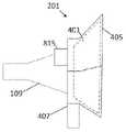
转向附图,图3示出了具有反射器重新指向设备201的反射器天线200。反射器重新指向设备201使得反射器天线200的主波束能够相对于没有安装重新指向设备201的天线200的原始角度以固定和确定的角度被操纵(steer)。反射器重新指向设备201安装在反射器的馈电喇叭109上方,其位置和取向由设备本身控制。位置和取向被设置成使得对于给定地理位置内的已经指向特定卫星213(图2(a))的反射器天线200,反射器重新指向设备的安装将使天线转换为反而指向单独的特定卫星215,而无需物理地移动反射器103或馈电喇叭109。单独的设备201或相同设备201的不同取向可以实现在标称角度+/-10度范围内的扫描。这不是硬性限制,但与未安装反射器重新指向设备的标称情况相比,进一步扫描将导致更显著的性能劣化。作为具体示例,通过安装被专门设计用于在馈电109上移位5度的设备201,可以将位于(例如)华盛顿特区50英里范围内并被配置成接收来自50°W处的卫星的信号的天线200转换为反而接收来自45°W处的卫星的信号,而无需熟练的安装或指向校准。Turning to the drawings, FIG. 3 shows a
为方便起见,以下部分将信号和场描述为从天线和反射器朝向一颗或另一颗卫星发射。来自卫星的发射与通过天线的接收的交互(reciprocal behavior)行为没有被描述,但与所描述的情况完全类似。For convenience, the following sections describe signals and fields as being emitted from antennas and reflectors towards one or another satellite. The reciprocal behavior of the transmission from the satellite and the reception through the antenna is not described, but is completely analogous to the situation described.
参考图2(a),喇叭天线109在典型操作中定位成使得喇叭的孔径位于抛物面反射器103的焦点203处。在图2(a)所示的典型操作中,系统101被定向成使得来自喇叭的信号或天线场205与反射器103相互作用并被引导朝向期望的目标卫星213,从而形成波束207。参考图2(b),操纵系统101以形成朝向不同卫星215的波束211可以通过重新定向整个天线101来执行,但也可以通过将馈电喇叭109远离反射器103的焦点203移位来执行。来自偏移喇叭的天线场209然后与反射器103相互作用以形成指向备用卫星215的波束211。然而,重新定向整个天线101或物理地移动喇叭109都需要熟练的工人来执行以及在反射器的设计中对移动的支持,在大多数情况下在没有工具的情况下都不能作为改装操作容易地执行。Referring to FIG. 2( a ), the
转向图2(c),3,反射器重新指向设备201被添加到反射器103的焦点203处的喇叭109,以使通常将波束207指向原始卫星213的场205侧向移位,以反而产生指向备用卫星215的波束211。这里侧向移位指示与抛物面反射器的对称轴线垂直的方向,该方向也是馈电支撑臂的方向。侧向移位可以是水平的、竖向的或两者的组合,但应保持在与垂直于反射器轴线的原始馈电孔径对准的平面内,以确保表观的相位中心继续大致位于反射器103的焦平面上。馈电孔径的位置限定所有移位比较的起点。将场的角度侧向移位和潜在地校正有效地迫使反射器103表现得好像喇叭109在不同的位置,从而在新的、期望的方向上产生波束211。Turning to Figures 2(c), 3, a
现在参考图4,反射器重新指向设备201具有:微波棱镜或棱镜401,微波棱镜或棱镜401在棱镜401的一个或两个表面(图4的实施方式中的顶部表面和底部表面)处具有可选的抗反射涂层特征部403;设计用于将棱镜连接和固定到主机喇叭(host horn)109的安装系统或特征部407;以及用于保护免受天气影响的天线罩或其他盖状件405。所有术语微波棱镜、棱镜、微波透镜和透镜旨在应用于设备401,并且术语棱镜在本公开中用于包括微波棱镜。Referring now to FIG. 4 , the
微波棱镜的构造在实践和原理上与包括GRIN透镜在内的微波透镜有许多相似之处。棱镜表示主要目的是使波束或锥体、波束、或其他电磁能量分布弯曲或移位的屈光设备,而透镜表示主要目的是使锥体、波束或其他电磁能量扩展或收缩的屈光设备。这两个概念之间没有严格的区分,因为棱镜也可以设计成聚焦,透镜也可以设计成使能量弯曲。对于本公开,棱镜被认为更有意义,因为设备401的主要目的是使能量弯曲和移位,而不是扩大或收缩,尽管也可以包括一些扩大或收缩。The construction of microwave prisms has many similarities in practice and principle to microwave lenses, including GRIN lenses. Prism denotes a refractive device whose primary purpose is to bend or displace a beam or cone, beam, or other electromagnetic energy distribution, whereas lens denotes a refractive device whose primary purpose is to expand or contract a cone, beam, or other electromagnetic energy distribution. There is no strict distinction between the two concepts, since prisms can also be designed to focus and lenses can also be designed to bend energy. For this disclosure, a prism is considered more meaningful, since the primary purpose of the
棱镜401和安装特征部407特定于反射器天线101和随附喇叭109的特定品牌或型号,并且还将特定于特定卫星213、215。安装特征部407可以是例如紧固件(诸如螺栓、螺母、螺钉)或粘合剂。
如图4所示,在一个实施方式中,微波棱镜401具有本体402,本体402具有第一棱镜表面402a和与第一表面402a相反的第二棱镜表面402b。棱镜本体402具有顶部、底部和至少一个侧面,并且可以具有任何合适形状的截面,诸如圆形、方形或矩形的截面。第一棱镜表面402a在本体402的顶部处,第二棱镜表面402b在本体402的底部处。第一棱镜表面402a和第二棱镜表面402b是平面的。抗反射涂层特征部403可以是施加到第一棱镜表面402a和第二棱镜表面402b的涂层。在一个实施方式中,抗反射涂层特征部具有顶部涂层表面和底部涂层表面,并且第一涂层特征部403a具有接触棱镜本体402的顶部棱镜表面402a的底部涂层表面,以及第二涂层特征部403b具有接触棱镜本体402的底部棱镜表面402b的顶部涂层表面。As shown in FIG. 4 , in one embodiment, the
在图4的实施方式中,棱镜是平行板棱镜。第一棱镜表面402a平行于第二棱镜表面402b。此外,喇叭109的张开侧形成向前敞开口部,张开侧的前边缘形成平面的前周边。喇叭109还具有从喇叭的后部延伸到喇叭的前部的中央纵向轴线。第一棱镜表面402a和第二棱镜表面402b基本上平行于喇叭109的平面口部,并且垂直于喇叭109的纵向轴线。In the embodiment of Figure 4, the prisms are parallel plate prisms. The
在一个实施方式中,喇叭109和反射器重新指向设备201可以反而连接到公共支撑件,诸如框架或壳体,并且安装系统或特征部407可以将反射器重新指向设备201连接到支撑件而不是连接到喇叭109。In one embodiment,
棱镜401通过由安装特征部407强制执行的以规定的取向靠近或位于喇叭天线109的孔径处定位而起作用。在图5中,当适当定位时,相对于在没有棱镜401的情况下来自喇叭109的天线场的原始或未受干扰的场位置506,棱镜401在进入和离开设备的输入和输出场505的对应位置中产生侧向偏移507。
从馈电喇叭发出的天线场不像来自激光器的天线场那样高度准直(由于微波的波长比激光的短波长要长得多),而是这些场以球形或锥形方式在馈电喇叭109和反射器103之间扩展。由于激光和微波之间的这种差异,因此反射器重新指向设备201可以包括校正,以允许从喇叭发出锥形的能量,这与用于光学目的的简单平面波束移位器不同。例如,反射器重新指向设备201可以具有非零光功率的非平面表面(特别是底部棱镜表面402b和/或顶部棱镜表面402a),以对从重新指向设备201出来的输出场的有效相位中心的场曲和轴向位置进行校正。The antenna fields emanating from the feed horn are not as highly collimated as those from the laser (due to the much longer wavelength of the microwave than the short wavelength of the laser), but rather these fields are distributed in a spherical or conical manner around the
棱镜401的核心操作是使场与喇叭109的位置相比侧向移位。这可以以任何合适的方式实现,其一些示例在图5(a)至图5(f)的实施方式中示出和描述为反射器重新指向设备201的各种配置。The core operation of
参考图5(a),最简单的选项是将微波棱镜401配置成由均匀的高介电常数形成的光学波束移位器或平行板棱镜401a。棱镜401相对于喇叭天线109保持在规定的角度,更具体地,第一表面402a和/或第二表面402b相对于喇叭109的敞开口部的平面成一角度并且相对于喇叭109的中央纵向轴线成一角度。这可以可选地包括抗反射层403以支持更高的性能。然而,为了产生最大的侧向移位或偏移507,该实施方式可能要求棱镜非常厚,具有高的场入射角(这限制了透射效率),以及大的介电常数ε。这些因素相结合,使棱镜选项401a体积庞大且笨重。Referring to Figure 5(a), the simplest option is to configure the
在图5(b)中,另一棱镜401b包括耦合和抗反射层,以利用一系列一个或更多个楔形件508更平滑地转换贯穿结构的信号的方向。棱镜401b具有中央本体或中央板502,中央本体或中央板502具有平行形状,与棱镜401a一样,并且一个或更多个楔形件508连接(例如,通过粘合剂)到中央本体或中央板502或与中央本体或中央板502一体形成,从而从中央板502的顶部和/或底部向外延伸。第一组一个或更多个楔形件508a布置在主体502的第一侧(顶部)处,并且第二组一个或更多个楔形件508b布置在主体502的第二侧(底部)处。In Figure 5(b), another
楔形件508可以具有任何合适的形状。然而,在所示的实施方式中,每个楔形件508的形状基本上是三角形的,具有面向主体502的第一平面初级表面、背离主体502的第二平面初级表面和小的次级表面。第一组楔形件508a的最底部楔形件的底部表面接触主体502的顶部表面502a,每个楔形件的顶部表面接触相邻楔形件的底部表面。第二组楔形件508b的最顶部楔形件的顶部表面接触主体502的底部表面502b,每个楔形件的底部表面接触相邻楔形件的顶部表面。Wedge 508 may have any suitable shape. However, in the illustrated embodiment, each wedge 508 is substantially triangular in shape, having a first planar primary
每个楔形件具有在第一初级表面和第二初级表面之间形成的锐角。在一个实施方式中,第一组楔形件508a具有可以与主体502的底部表面402b相对于喇叭109的口部的平面的偏移角θ相同的组合角。并且第二组楔形件508b具有可以与主体502的顶部表面402a相对于喇叭109的口部的平面的偏移角θ相同的组合角。因此,下部楔形件组的最底部楔形件508b的底部楔形件表面基本上平行于喇叭口部的平面和顶部楔形件组的最顶部楔形件508a的顶部楔形件表面。因此,顶部楔形件组508a的锐角在主体502的一侧(即,图5(b)的实施方式中的左侧)处被对准,而底部楔形件组508b的锐角在与主体502的相对侧(即右侧)处被对准。在这种配置中,信号基本平行于原始信号轴线506并从原始信号轴线506偏移地出现,原始信号轴线506也可以平行于中央喇叭纵向轴线。Each wedge has an acute angle formed between the first primary surface and the second primary surface. In one embodiment, the first set of
在一个实施方式中,每个楔形件508的多个介电层ε1、ε2、ε3、ε4和ε5的介电常数随着离中央板502越远而依次地越高,其中ε1最低,ε5最高。即,中央板502具有最高的介电常数,并且与中央板502相邻的每个楔形件508具有依次降低的介电常数。这种设计允许随着层数的增加和每层的更小场入射角而增加透射效率,但对最小化设计的尺寸和质量几乎没有作用。因此,每个楔形件508使信号折射。并且底部楔形件组508b中的每个楔形件508递增地增加信号相对于原始轴线506的角度。并且顶部楔形件组508a中的每个楔形件508减小信号相对于原始轴线506的角度,直到信号基本上平行于原始轴线506或者相对于原始轴线506处于期望的角度。抗反射涂层403可以放置在顶部楔形件506a的顶部处和底部楔形件506b的底部处。In one embodiment, the dielectric constants of the plurality of dielectric layers ε1 , ε2 , ε3 , ε4 , and ε5 of each wedge 508 sequentially increase with distance from the
转向图5(c),棱镜401c示出为具有超颖材料和超颖表面技术,其也可以包括发射阵概念。该实施方式通过减少所需材料的体积来减少棱镜401c的质量,但相应地减少了操作带宽并增加了插入损耗。与使用由介电常数和形状来限定其特性的体电介质不同,超颖表面棱镜具有由支撑结构悬浮在空气中的一层或更多层超颖材料或超颖表面。Turning to FIG. 5( c ),
对于该实现方式,棱镜401c可以由空间上变化的超颖材料或超颖表面的两个层531、535来构造,空间上变化的超颖材料或超颖表面通过在发射的场中引入相位梯度来在两个点处改变来自喇叭109的场的方向。超颖材料或超颖表面棱镜不像常规棱镜那样依赖介电区域内的折射,并且不包括401a和401b中包括的介电区域。因此,底部超颖材料或超颖表面531将信号远离原始信号轴线506进行折射,使得信号相对于原始信号轴线506以一角度行进。并且顶部超颖材料或超颖表面535将信号折射回以与原始信号轴线506平行。双折射使信号从原始信号轴线506偏移并与原始信号轴线506平行。For this implementation, the
需要两个层531、535之间的间隙或间隔以允许用于场传播并产生侧向偏移的距离。间隔越大,侧向偏移越大。间隔由棱镜结构内部的机械结构533保持,机械结构533将层531、535之间的空间保持为空气间隙。例如,机械结构533可以是支撑件或梁,并且层531、535中的一个或两个层可以在保持它们之间的期望空气间隙距离的不同位置处连接到支撑件。棱镜内部的这种支撑结构在目的和实现上与将棱镜401保持到馈电109的结构407分开,并且可以使用支撑件、螺栓、夹子或其他物理特征部来实现以保持两个层531和535之间的固定间距。形成层531和535的人造电介质或超颖表面结构需要在每个层531和535的表面上对其结构进行周期性改变,以在表面上建立相位梯度并因此操纵波束,这限制了设计的可用带宽。超颖材料和超颖表面设计通常是窄带和有损的,但对于某些应用可能就足够了。通过两个层的透射效率是这种实现方式的关键指标。A gap or spacing between the two
在图5(d)中,示出了减小结构的厚度的波纹棱镜401d。这进而减小了重量,因为支撑结构407和天线罩405也可以更小。通过在棱镜401d的顶部表面和底部表面引入成形波纹也减小了401a和401b中所示的棱镜的大高度。波纹具有锯齿型形状。从左边开始,顶部表面的每个齿都具有基本上与喇叭的纵向轴线平行的直的引导上升沿,然后是成角度的拖尾下降沿。In Figure 5(d), a
棱镜401d示出了棱镜401a的折叠版本,但同样的方法可以应用于多层401b。通过在顶部表面和底部表面401d中使用菲涅耳式波纹来折叠(collapsing)棱镜的尺寸和形状,可以保持大致相同的波束操纵特性,但棱镜的高度降低。这将产生限制操作带宽的分散效应,但可能具有比超颖表面/超颖材料方法更小的分散。抗反射涂层可以应用于401d的顶部波纹表面和底部波纹表面,并将遵循波纹本身的形状。底部表面使信号折射以相对于原始信号轴线506形成一角度,而顶部表面将信号折射回以平行于原始信号轴线506(并从原始信号轴线506偏移)。
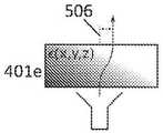
在图5(e)中,具有对内部介电常数(x,y,z)的完全控制的渐变折射率(graded-index)或非均匀棱镜401e提供了将功能折叠成最小可能的连续封装件的显著好处。平滑变化(连续)和阶梯式梯度设计的挑战是制造实现必要性能所需的通常复杂的形状和结构。In Figure 5(e), a graded-index or
参考图5(f),示出了两个半棱镜401f。由于棱镜401的质量是重新指向设备201的设计中的主要因素,因此可以采取其他措施来减少棱镜的质量,包括下述棱镜,在所述棱镜中,在不需要时去除棱镜的内部中的电介质的区域,从而有效地形成彼此隔开一距离或空气间隙的两个半棱镜401f。在一些实现方式中,该间隙可以被实现,中空空气区域可以被构造在否则为实心的棱镜内,从而减小重量但不需要类似于支撑件533的单独的安装或支撑结构。半棱镜401f可以具有三角形形状,具有平面的或弯曲的表面。如图所示,上半棱镜可以具有弯曲成略微凹入的朝向内的表面,而下半棱镜可以具有弯曲成略微凸出的朝向内的表面。上半棱镜的朝向内的表面面向下半棱镜的朝向内的表面并具有与下半棱镜的朝向内的表面匹配的形状。将棱镜的内表面的轮廓与场在每个角度的传播方向相匹配,允许场继续是直的而不会在界面处发生折射,就好像被去除的材料仍然在那里一样。当可用电介质的损耗正切与空气相比高时,这种质量减小方法也很有用。下半棱镜401f的底部表面与喇叭口部的平面成θ角,并将信号折射成与原始信号轴线506成一角度。下半棱镜401f的顶部表面进一步使信号折射。上半棱镜401f的底部表面将信号折射回以平行于原始信号轴线506,上半棱镜401f的上表面进一步将信号折射成平行于原始信号轴线506并从原始信号轴线506偏移。上半棱镜和下半棱镜401f之间的距离越大,信号与原始信号轴线506的可实现侧向偏移越大。Referring to Figure 5(f), two
因为传播通过介电区域的场不会像它们仅传播通过空气那样扩展,所以来自设备201的场的有效相位中心可能不再与反射器匹配。即使侧向位置可能是正确的,馈电分布的相位中心到反射器的距离仍然需要与反射器的焦距相匹配,以保持孔径效率。包括非零光学增益(通过表面的曲率或内部介电梯度)可以用于校正场的角分布以及有效相位中心。Because fields propagating through dielectric regions do not spread as they would propagating through air alone, the effective phase center of the field from
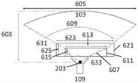
棱镜401的所需尺寸由场所需的侧向移位程度和反射器的几何形状共同确定。好的棱镜应该小、重量轻、紧凑,以最小化成本并简化安装。然而,棱镜401的尺寸必须设置成拦截来自馈电喇叭的所有功率并将所有能量重新定向到反射器。The required size of the
参考图6,对于具有小f/D(焦距603与直径605)比或等效地宽照明锥体角度609的反射器,确定厚度的特定棱镜611实现方式必须在侧向方向上足够大以从棱镜基部处的喇叭覆盖原始辐射模式锥体631,在棱镜611的出口处足够大以在重新定心的锥体633的整个表面上释放能量,并允许足够的内部厚度615和宽度613以充分重塑能量以遵循期望的路径607。如果需要更厚的625棱镜621实现方式以提供必要的侧向移位(通常,进一步的移位需要更厚的棱镜以提供更多空间来传播),那么棱镜(至少在输出处)也必须更宽623,从而使棱镜的体积和质量(大致上,通常)与棱镜厚度的立方成比例。这导致了在实现其他性能参数的同时最小化棱镜厚度以便还控制质量的必要要求。Referring to FIG. 6, for reflectors with small f/D (
f/D比还影响将反射器操纵到给定角度所需的侧向移位的量。与许多普通消费者DTH天线一样,具有低f/D比的反射器允许有效馈电位置109的小改变以产生波束扫描角度的较大移位。The f/D ratio also affects the amount of lateral displacement required to steer the reflector to a given angle. As with many common consumer DTH antennas, reflectors with low f/D ratios allow small changes in the
具有高f/D的反射器将需要较小的棱镜来将孔径场移位给定距离,因为锥体角度很小,但将需要较大的物理移位才能获得以度为单位的主波束的相同扫描角度。A reflector with a high f/D will require a smaller prism to shift the aperture field a given distance because the cone angle is small, but will require a larger physical shift to obtain the main beam's in degrees Same scan angle.
在一个实施方式中,反射器重新指向设备201被改装到(并且连接,诸如通过紧固件机构、粘合剂等)现有喇叭天线。因此,它被配置成与现有的喇叭天线和抛物面反射器一起工作。棱镜401的特性被设计成适合天线系统101。然而,在其他实施方式中,喇叭天线和抛物面反射器可以设计成与设备201一起工作,这将涉及准备好轻松和精确地安装设备201的安装特征部407、用以支撑设备201的额外重量而不会偏斜的坚固的安装臂107(图1)、以及用以优化整个系统201的质量的足够大的f/D比。In one embodiment,
对于给定的卫星对,现任卫星213和新目标卫星215(图2),必须由反射器重新指向设备201应用的校正角度和相对于当前天线指向方向的偏移应该应用于的方向是基于两颗卫星之间的角距离和在地球上卫星被观测到的位置。For a given pair of satellites, the
图7示出了在地面上必须应用的不同角度。由于用于DTH的相对较小直径的反射器103(典型地在40至80cm之间)具有相当宽的波束,因此校正的分辨率非常粗糙。基于反射器重新指向设备201的目标安装位置,查阅类似于图7的图表并选择必要的校正角度和方向。然后,通过每个组合的独立棱镜和安装设计中的实现方式或者通过可调整夹具或安装布置来应用校正角度和方向,使用用于更广泛的地理地区的单个棱镜和夹具设计来适当地设置扫描角度和方向。棱镜有效地围绕喇叭天线109的中央轴线旋转校正角度,以便基于系统200的位置使所得波束指向目标卫星。棱镜或设置选择可以在将设备运送给最终用户前进行,或者可以向最终用户提供使用取决于他们位置的特定编号的或有标签的设置的说明,即说明可能写着“对于您的邮政编码ABC,在安装在您的天线上之前,旋转安装夹子以将箭头与位置D对准”。Figure 7 shows the different angles that must be applied on the ground. Since relatively small diameter reflectors 103 (typically between 40 and 80 cm) for DTH have rather wide beams, the resolution of the correction is very coarse. Based on the target installation location for the
这些说明将适用于图8(a)和图8(b)所示的实现方式。喇叭天线109示出为在点811处以其中心进行安装。棱镜401(仅出于说明性目的而示出,但包含在设备201的天线罩405内)使喇叭的场移位以在离开棱镜时重定心到点813。在外壳体或天线罩材料上设置一组棘爪和对准标记,以便由最终用户或在运送之前进行可调整地对准。对准标记允许用户调整安装结构以设置微波棱镜相对于反射器天线(具体地相对于喇叭馈电109)的可调整位置和可调整取向。也就是说,安装结构407固定地将设备201附接到天线101,但在由可调整对准标记限定的位置和取向处。对准特征部限定微波棱镜相对于安装结构的多个位置和取向,并且可以基于地理位置在工厂设置。最终用户然后可以基于安装位置的地理位置来确定(诸如通过使用图7的地图)适当的设置。These descriptions will apply to the implementations shown in Figures 8(a) and 8(b).
改变棱镜401相对于馈电喇叭109的中央轴线的取向改变了重新操纵的波束相对于原始安装的天线的角度。例如,棱镜可以围绕馈电喇叭109中央轴线旋转,使得所得波束指向原始波束方向的东或西,以及调整波束指向地平线上方的仰角以准确地指向期望的卫星215。可以设置一个或更多个支撑构件或紧固构件来移动棱镜401。例如,紧固构件可以将棱镜401可移动地连接到天线罩405或安装结构407,使得棱镜401可以改变相对于馈电喇叭109的取向。Changing the orientation of
图8(c)示出了与位置A对准的设备401,而图8(a)示出了与位置E对准的设备401。这里,注意从喇叭出现的信号被棱镜偏移,如图5(a)至图5(f)所示。对准件817可以连接到棱镜401,使得在各个位置之间旋转对准件817,也旋转了整个棱镜401。当棱镜和对准件817位于位置E时(图8(a)),棱镜的相位中心813从喇叭的相位中心811偏移。更具体地,棱镜的相位中心813相对于喇叭的相位中心811大约位于2点钟方向。当棱镜和对准件817位于位置A时(图8(c)),棱镜的相位中心813相对于喇叭的相位中心811在大约4点钟方向。因此,棱镜的相位中心813随着对准的旋转而旋转,这进而使由棱镜输出的信号移动。在另一实施方式中,对准的不同位置可以为棱镜产生不同的角度。Figure 8(c) shows
棱镜401可以采取任何形状或相对于馈电喇叭的不同方向,如先前在图4至图6中描述的,然后天线罩的形状和边界被选择成适当地覆盖棱镜。The
在对准可调整对准件817之后,设备将以任何合适的方式固定地连接到喇叭。例如,安装系统407可以包括卡扣连接器819,该卡扣连接器卡到天线的安装杆上,由喇叭护罩815稳定和定向。一旦安装,设备现在将使反射器将其主波束指向新的期望的卫星215。安装特征部407将设备固定地保持在适当位置,以拦截来自喇叭109的所有场,否则场将到达反射器103,并使场侧向移位以引起反射器天线101的扫描角度的变化。在天线101和设备201的适当操作期间不需要进一步的运动或活动。如果期望天线再次重新指向原始现任卫星213,则可以通过拆卸安装特征部819来移除设备201。After aligning the
注意,附图可以说明,并且描述和权利要求可以使用几何或关系术语,诸如右、左、之上、之下、上、下、侧面、顶部、底部、伸长、平行、侧向、正交、角度、矩形、方形、环形、圆形、轴线。这些术语并非旨在限制本公开,并且通常用于方便有助于基于附图中所示示例的描述。此外,几何或关系术语可能不准确。例如,信号和平面可能不完全垂直或相互平行,但仍可能被认为是垂直或平行的。Note that the drawings may illustrate, and the description and claims may use geometric or relational terms, such as right, left, above, below, above, below, side, top, bottom, elongated, parallel, lateral, orthogonal , angle, rectangle, square, ring, circle, axis. These terms are not intended to limit the present disclosure, and are generally used for convenience to facilitate description based on the examples shown in the drawings. Also, geometric or relational terms may not be accurate. For example, signals and planes may not be perfectly perpendicular or parallel to each other, but may still be considered to be.
前述描述和附图应被认为仅是对本公开的原理的说明。系统可以被配置成多种形状和尺寸并且不旨在受实施方式的限制。本领域技术人员将容易想到系统的许多应用。因此,不希望将本公开限制于所公开的具体示例或所示和所描述的确切构造和操作。更确切的说,可以采取落入本公开的范围内的所有合适的修改和等效物。The foregoing description and drawings should be considered as illustrative only of the principles of the disclosure. The system can be configured in many shapes and sizes and is not intended to be limited by the implementation. Many applications for the system will readily occur to those skilled in the art. Accordingly, it is not intended to limit the disclosure to the particular examples disclosed, or to the exact construction and operation shown and described. Rather, all suitable modifications and equivalents falling within the scope of this disclosure may be employed.
Claims (18)
Translated fromChineseApplications Claiming Priority (3)
| Application Number | Priority Date | Filing Date | Title |
|---|---|---|---|
| US202062981367P | 2020-02-25 | 2020-02-25 | |
| US62/981,367 | 2020-02-25 | ||
| PCT/IB2021/051453WO2021171157A1 (en) | 2020-02-25 | 2021-02-19 | Prism for repointing reflector antenna main beam |
Publications (1)
| Publication Number | Publication Date |
|---|---|
| CN115315848Atrue CN115315848A (en) | 2022-11-08 |
Family
ID=75267529
Family Applications (1)
| Application Number | Title | Priority Date | Filing Date |
|---|---|---|---|
| CN202180016990.6APendingCN115315848A (en) | 2020-02-25 | 2021-02-19 | Prism for redirecting the main beam of a reflector antenna |
Country Status (10)
| Country | Link |
|---|---|
| US (3) | US11469515B2 (en) |
| EP (1) | EP4111531A1 (en) |
| JP (1) | JP7724225B2 (en) |
| CN (1) | CN115315848A (en) |
| AU (1) | AU2021227766A1 (en) |
| BR (1) | BR112022016560A2 (en) |
| CA (1) | CA3170825A1 (en) |
| MX (1) | MX2022010547A (en) |
| WO (1) | WO2021171157A1 (en) |
| ZA (1) | ZA202210213B (en) |
Families Citing this family (2)
| Publication number | Priority date | Publication date | Assignee | Title |
|---|---|---|---|---|
| CN115315848A (en)* | 2020-02-25 | 2022-11-08 | 全部.空间网络有限公司 | Prism for redirecting the main beam of a reflector antenna |
| CN114914701B (en)* | 2022-05-12 | 2024-10-15 | 中国人民解放军空军工程大学 | Beam reconfigurable origami spatially ordered gradient phase metasurface and its design method |
Citations (3)
| Publication number | Priority date | Publication date | Assignee | Title |
|---|---|---|---|---|
| US20150048963A1 (en)* | 2013-08-14 | 2015-02-19 | Vega Grieshaber Kg | Radar beam deflection unit for a radar level indicator |
| EP3446362A1 (en)* | 2016-04-22 | 2019-02-27 | Thales | System for deflecting and pointing a microwave beam |
| US20190131704A1 (en)* | 2017-11-01 | 2019-05-02 | Searete Llc | Aperture Efficiency Enhancements Using Holographic and Quasi-Optical Beam Shaping Lenses |
Family Cites Families (65)
| Publication number | Priority date | Publication date | Assignee | Title |
|---|---|---|---|---|
| US4333082A (en)* | 1980-03-31 | 1982-06-01 | Sperry Corporation | Inhomogeneous dielectric dome antenna |
| US4531129A (en) | 1983-03-01 | 1985-07-23 | Cubic Corporation | Multiple-feed luneberg lens scanning antenna system |
| GB8717845D0 (en) | 1987-07-28 | 1987-09-03 | Univ London | Refracting elements |
| WO1992013373A1 (en) | 1991-01-28 | 1992-08-06 | Thomson Consumer Electronics S.A. | Antenna system |
| JPH04328480A (en)* | 1991-04-30 | 1992-11-17 | Robotec Kenkyusho:Kk | Scanning beam antenna system apparatus |
| US5736959A (en) | 1991-10-28 | 1998-04-07 | Teledesic Corporation | Earth-fixed cell beam management for satellite communication system using dielectic lens-focused scanning beam antennas |
| CA2157139A1 (en) | 1994-09-01 | 1996-03-02 | Thomas C. Weakley | Multiple beam antenna system for simultaneously receiving multiple satellite signals |
| US6121939A (en) | 1996-11-15 | 2000-09-19 | Yagi Antenna Co., Ltd. | Multibeam antenna |
| US6075497A (en) | 1997-06-30 | 2000-06-13 | Acer Neweb Corp. | Multiple-feed electromagnetic signal receiving apparatus |
| US6160520A (en) | 1998-01-08 | 2000-12-12 | E★Star, Inc. | Distributed bifocal abbe-sine for wide-angle multi-beam and scanning antenna system |
| US6181293B1 (en) | 1998-01-08 | 2001-01-30 | E*Star, Inc. | Reflector based dielectric lens antenna system including bifocal lens |
| US6107897A (en) | 1998-01-08 | 2000-08-22 | E*Star, Inc. | Orthogonal mode junction (OMJ) for use in antenna system |
| US6218853B1 (en) | 1998-12-11 | 2001-04-17 | Daniel Liu | Circuit arrangement for simulating alternating current load |
| CN2370427Y (en)* | 1999-02-12 | 2000-03-22 | 中国科学院紫金山天文台 | Wave beam modulator |
| US6593893B2 (en) | 2000-03-06 | 2003-07-15 | Hughes Electronics Corporation | Multiple-beam antenna employing dielectric filled feeds for multiple and closely spaced satellites |
| US6710749B2 (en) | 2000-03-15 | 2004-03-23 | King Controls | Satellite locator system |
| SE522925C2 (en) | 2001-03-08 | 2004-03-16 | Telewide Ab | Receiving signals from multiple satellites in a single antenna |
| US6512485B2 (en) | 2001-03-12 | 2003-01-28 | Wildblue Communications, Inc. | Multi-band antenna for bundled broadband satellite internet access and DBS television service |
| ATE343856T1 (en) | 2001-09-28 | 2006-11-15 | Sumitomo Electric Industries | RADIO WAVE LENS ANTENNA DEVICE |
| JP2005526437A (en) | 2002-05-16 | 2005-09-02 | イーエムエス テクノロジーズ インコーポレイテッド | Scanning directional antenna with lens and reflector assembly |
| EP1543579A1 (en) | 2002-08-20 | 2005-06-22 | Aerosat Corporation | Communication system with broadband antenna |
| CN100533856C (en) | 2003-01-30 | 2009-08-26 | 住友电气工业株式会社 | Lens Antenna Assembly |
| JP2004304737A (en) | 2003-04-01 | 2004-10-28 | Seiko Epson Corp | Antenna device and method of manufacturing the same |
| DE602004015955D1 (en) | 2003-04-02 | 2008-10-02 | Sumitomo Electric Industries | RADIO WAVES LENS ANTENNA DEVICE |
| US7236681B2 (en) | 2003-09-25 | 2007-06-26 | Prodelin Corporation | Feed assembly for multi-beam antenna with non-circular reflector, and such an assembly that is field-switchable between linear and circular polarization modes |
| US7446721B2 (en) | 2004-03-11 | 2008-11-04 | Intellian Technologies Inc. | Satellite tracking antenna system and method therefor |
| US7342551B2 (en) | 2004-04-13 | 2008-03-11 | Electronic Controlled Systems | Antenna systems for reliable satellite television reception in moisture conditions |
| US20050280593A1 (en) | 2004-06-22 | 2005-12-22 | Seung-Hyeon Cha | Satellite tracking antenna and method using rotation of a subreflector |
| US7511677B2 (en) | 2004-07-13 | 2009-03-31 | Mediaur Technologies, Inc. | Satellite ground station antenna with wide field of view and nulling pattern |
| US7522115B2 (en) | 2004-07-13 | 2009-04-21 | Mediaur Technologies, Inc. | Satellite ground station antenna with wide field of view and nulling pattern using surface waveguide antennas |
| US7526249B2 (en) | 2004-07-13 | 2009-04-28 | Mediaur Technologies, Inc. | Satellite ground station to receive signals with different polarization modes |
| JP2006166399A (en) | 2004-11-15 | 2006-06-22 | Maspro Denkoh Corp | Antenna system for emc test, test signal generation apparatus and transmission apparatus |
| JP2006145399A (en) | 2004-11-19 | 2006-06-08 | Matsushita Electric Ind Co Ltd | Automotive radar equipment |
| US7375698B2 (en) | 2005-12-02 | 2008-05-20 | Andrew Corporation | Hydrophobic feed window |
| US7656345B2 (en)* | 2006-06-13 | 2010-02-02 | Ball Aerospace & Technoloiges Corp. | Low-profile lens method and apparatus for mechanical steering of aperture antennas |
| KR101354151B1 (en) | 2006-08-24 | 2014-01-28 | 삼성전자주식회사 | Method and apparatus for transforming and inverse-transforming image |
| GB2442796A (en) | 2006-10-11 | 2008-04-16 | John Thornton | Hemispherical lens with a selective reflective planar surface for a multi-beam antenna |
| US8604989B1 (en) | 2006-11-22 | 2013-12-10 | Randall B. Olsen | Steerable antenna |
| US7463214B2 (en) | 2007-03-30 | 2008-12-09 | Itt Manufacturing Enterprises, Inc. | Method and apparatus for steering radio frequency beams utilizing photonic crystal structures |
| US7642978B2 (en) | 2007-03-30 | 2010-01-05 | Itt Manufacturing Enterprises, Inc. | Method and apparatus for steering and stabilizing radio frequency beams utilizing photonic crystal structures |
| US8982004B1 (en) | 2007-08-03 | 2015-03-17 | The Directv Group, Inc. | Integrated ODU controller for antenna pointing |
| GB0810075D0 (en) | 2008-05-03 | 2008-07-09 | Raven Mfg Ltd | Satellite date receiving apparatus |
| US7982687B1 (en) | 2008-10-02 | 2011-07-19 | The Directv Group, Inc. | Ka/Ku outdoor unit configuration using a frequency selective surface |
| WO2011014919A1 (en) | 2009-08-04 | 2011-02-10 | Bae Systems Australia Limited | A multi-band antenna |
| US8576132B2 (en) | 2009-10-22 | 2013-11-05 | Lockheed Martin Corporation | Metamaterial lens feed for multiple beam antennas |
| US20110109501A1 (en) | 2009-11-06 | 2011-05-12 | Viasat, Inc. | Automated beam peaking satellite ground terminal |
| US20160079682A1 (en) | 2010-07-30 | 2016-03-17 | Spatial Digital Systems, Inc. | Polarization Re-alignment for Mobile Satellite Terminals |
| TWI449445B (en) | 2010-10-07 | 2014-08-11 | Wistron Neweb Corp | Beamwidth adjustment device |
| KR101919581B1 (en) | 2011-03-09 | 2018-11-19 | 트라네 앤드 트라네 아/에스 | Device for switching between linear and circular polarization using a rotatable depolarizer |
| WO2012129240A2 (en)* | 2011-03-20 | 2012-09-27 | Viasat, Inc. | Manually repointable satellite antenna |
| WO2012161612A1 (en) | 2011-05-23 | 2012-11-29 | Autonomous Non-Commercial Organization "Research Institute "Sitronics Labs"" | Electronically beam steerable antenna device |
| US8810468B2 (en)* | 2011-06-27 | 2014-08-19 | Raytheon Company | Beam shaping of RF feed energy for reflector-based antennas |
| WO2014193257A1 (en) | 2013-05-27 | 2014-12-04 | Limited Liability Company "Radio Gigabit" | Lens antenna |
| KR101477199B1 (en) | 2013-07-03 | 2014-12-29 | (주)인텔리안테크놀로지스 | Satellite receiving/transmitting anttena having structure for switching multiple band signal |
| US20150116155A1 (en) | 2013-10-25 | 2015-04-30 | The Charles Stark Draper Laboratory, Inc. | Methods and systems for self-aligning high data rate communication networks |
| US9722316B2 (en) | 2014-07-07 | 2017-08-01 | Google Inc. | Horn lens antenna |
| US10122085B2 (en) | 2014-12-15 | 2018-11-06 | The Boeing Company | Feed re-pointing technique for multiple shaped beams reflector antennas |
| US9620855B2 (en) | 2015-07-20 | 2017-04-11 | Elwha Llc | Electromagnetic beam steering antenna |
| US9577327B2 (en) | 2015-07-20 | 2017-02-21 | Elwha Llc | Electromagnetic beam steering antenna |
| US10553943B2 (en) | 2015-09-22 | 2020-02-04 | Qualcomm Incorporated | Low-cost satellite user terminal antenna |
| US10158177B2 (en) | 2016-03-11 | 2018-12-18 | Scott Cook | Antenna horn with suspended dielectric tuning vane |
| WO2018017518A2 (en) | 2016-07-21 | 2018-01-25 | Astronics Aerosat Corporation | Multi-channel communications antenna |
| US10116051B2 (en) | 2017-03-17 | 2018-10-30 | Isotropic Systems Ltd. | Lens antenna system |
| CN113131224B (en)* | 2020-01-16 | 2022-08-19 | 华为技术有限公司 | Antenna beam propagation direction adjustment system |
| CN115315848A (en)* | 2020-02-25 | 2022-11-08 | 全部.空间网络有限公司 | Prism for redirecting the main beam of a reflector antenna |
- 2021
- 2021-02-19CNCN202180016990.6Apatent/CN115315848A/enactivePending
- 2021-02-19AUAU2021227766Apatent/AU2021227766A1/enactivePending
- 2021-02-19MXMX2022010547Apatent/MX2022010547A/enunknown
- 2021-02-19WOPCT/IB2021/051453patent/WO2021171157A1/ennot_activeCeased
- 2021-02-19JPJP2022550797Apatent/JP7724225B2/enactiveActive
- 2021-02-19CACA3170825Apatent/CA3170825A1/enactivePending
- 2021-02-19EPEP21714943.4Apatent/EP4111531A1/enactivePending
- 2021-02-19BRBR112022016560Apatent/BR112022016560A2/enunknown
- 2021-02-23USUS17/182,992patent/US11469515B2/enactiveActive
- 2022
- 2022-09-13USUS17/943,895patent/US11888228B2/enactiveActive
- 2022-09-14ZAZA2022/10213Apatent/ZA202210213B/enunknown
- 2023
- 2023-12-12USUS18/536,580patent/US20240128655A1/enactivePending
Patent Citations (3)
| Publication number | Priority date | Publication date | Assignee | Title |
|---|---|---|---|---|
| US20150048963A1 (en)* | 2013-08-14 | 2015-02-19 | Vega Grieshaber Kg | Radar beam deflection unit for a radar level indicator |
| EP3446362A1 (en)* | 2016-04-22 | 2019-02-27 | Thales | System for deflecting and pointing a microwave beam |
| US20190131704A1 (en)* | 2017-11-01 | 2019-05-02 | Searete Llc | Aperture Efficiency Enhancements Using Holographic and Quasi-Optical Beam Shaping Lenses |
Also Published As
| Publication number | Publication date |
|---|---|
| EP4111531A1 (en) | 2023-01-04 |
| US11888228B2 (en) | 2024-01-30 |
| AU2021227766A1 (en) | 2022-09-01 |
| WO2021171157A1 (en) | 2021-09-02 |
| MX2022010547A (en) | 2022-11-16 |
| ZA202210213B (en) | 2025-01-29 |
| CA3170825A1 (en) | 2021-09-02 |
| US20210265739A1 (en) | 2021-08-26 |
| US11469515B2 (en) | 2022-10-11 |
| JP7724225B2 (en) | 2025-08-15 |
| JP2023514436A (en) | 2023-04-05 |
| BR112022016560A2 (en) | 2023-01-10 |
| US20240128655A1 (en) | 2024-04-18 |
| US20230006358A1 (en) | 2023-01-05 |
Similar Documents
| Publication | Publication Date | Title |
|---|---|---|
| US20240128655A1 (en) | Prism for repointing reflector antenna main beam | |
| US8497810B2 (en) | Multi-band antenna system for satellite communications | |
| US7466281B2 (en) | Integrated waveguide antenna and array | |
| US6211842B1 (en) | Antenna with continuous reflector for multiple reception of satelite beams | |
| US11258172B2 (en) | Multi-beam shaped reflector antenna for concurrent communication with multiple satellites | |
| KR20010096501A (en) | Multibeam satellite communication antenna | |
| CN101584080A (en) | Integrated waveguide antenna array | |
| US7227501B2 (en) | Compensating structures and reflector antenna systems employing the same | |
| US12283750B2 (en) | Low profile multi band antenna system | |
| US20060125706A1 (en) | High performance multimode horn for communications and tracking | |
| US6747604B2 (en) | Steerable offset antenna with fixed feed source | |
| WO1999038228A1 (en) | Multi-primary radiator, down converter and multibeam antenna | |
| US6172649B1 (en) | Antenna with high scanning capacity | |
| US11791562B2 (en) | Ring focus antenna system with an ultra-wide bandwidth | |
| WO1989001246A1 (en) | Phase shifting element, antenna comprising phase shifting elements and method of steering an antenna | |
| JPS6251808A (en) | satellite receiving antenna equipment | |
| Gonzalo et al. | Space Antennas including Terahertz Antennas | |
| JP2014068334A (en) | Reception antenna device and manufacturing method for shaped reflector | |
| JPH03249806A (en) | Reception method for radio wave from geostationary satellite |
Legal Events
| Date | Code | Title | Description |
|---|---|---|---|
| PB01 | Publication | ||
| PB01 | Publication | ||
| SE01 | Entry into force of request for substantive examination | ||
| SE01 | Entry into force of request for substantive examination |