CN115315278A - Stent graft with radiopaque marker and method for producing the same - Google Patents
Stent graft with radiopaque marker and method for producing the sameDownload PDFInfo
- Publication number
- CN115315278A CN115315278ACN202080098911.6ACN202080098911ACN115315278ACN 115315278 ACN115315278 ACN 115315278ACN 202080098911 ACN202080098911 ACN 202080098911ACN 115315278 ACN115315278 ACN 115315278A
- Authority
- CN
- China
- Prior art keywords
- parylene
- graft
- stent
- layer
- radiopaque
- Prior art date
- Legal status (The legal status is an assumption and is not a legal conclusion. Google has not performed a legal analysis and makes no representation as to the accuracy of the status listed.)
- Granted
Links
Images


Classifications
- A—HUMAN NECESSITIES
- A61—MEDICAL OR VETERINARY SCIENCE; HYGIENE
- A61F—FILTERS IMPLANTABLE INTO BLOOD VESSELS; PROSTHESES; DEVICES PROVIDING PATENCY TO, OR PREVENTING COLLAPSING OF, TUBULAR STRUCTURES OF THE BODY, e.g. STENTS; ORTHOPAEDIC, NURSING OR CONTRACEPTIVE DEVICES; FOMENTATION; TREATMENT OR PROTECTION OF EYES OR EARS; BANDAGES, DRESSINGS OR ABSORBENT PADS; FIRST-AID KITS
- A61F2/00—Filters implantable into blood vessels; Prostheses, i.e. artificial substitutes or replacements for parts of the body; Appliances for connecting them with the body; Devices providing patency to, or preventing collapsing of, tubular structures of the body, e.g. stents
- A61F2/02—Prostheses implantable into the body
- A61F2/04—Hollow or tubular parts of organs, e.g. bladders, tracheae, bronchi or bile ducts
- A61F2/06—Blood vessels
- A61F2/07—Stent-grafts
- A—HUMAN NECESSITIES
- A61—MEDICAL OR VETERINARY SCIENCE; HYGIENE
- A61L—METHODS OR APPARATUS FOR STERILISING MATERIALS OR OBJECTS IN GENERAL; DISINFECTION, STERILISATION OR DEODORISATION OF AIR; CHEMICAL ASPECTS OF BANDAGES, DRESSINGS, ABSORBENT PADS OR SURGICAL ARTICLES; MATERIALS FOR BANDAGES, DRESSINGS, ABSORBENT PADS OR SURGICAL ARTICLES
- A61L31/00—Materials for other surgical articles, e.g. stents, stent-grafts, shunts, surgical drapes, guide wires, materials for adhesion prevention, occluding devices, surgical gloves, tissue fixation devices
- A61L31/14—Materials characterised by their function or physical properties, e.g. injectable or lubricating compositions, shape-memory materials, surface modified materials
- A61L31/18—Materials at least partially X-ray or laser opaque
- A—HUMAN NECESSITIES
- A61—MEDICAL OR VETERINARY SCIENCE; HYGIENE
- A61L—METHODS OR APPARATUS FOR STERILISING MATERIALS OR OBJECTS IN GENERAL; DISINFECTION, STERILISATION OR DEODORISATION OF AIR; CHEMICAL ASPECTS OF BANDAGES, DRESSINGS, ABSORBENT PADS OR SURGICAL ARTICLES; MATERIALS FOR BANDAGES, DRESSINGS, ABSORBENT PADS OR SURGICAL ARTICLES
- A61L31/00—Materials for other surgical articles, e.g. stents, stent-grafts, shunts, surgical drapes, guide wires, materials for adhesion prevention, occluding devices, surgical gloves, tissue fixation devices
- A61L31/04—Macromolecular materials
- A61L31/048—Macromolecular materials obtained by reactions only involving carbon-to-carbon unsaturated bonds
- A—HUMAN NECESSITIES
- A61—MEDICAL OR VETERINARY SCIENCE; HYGIENE
- A61L—METHODS OR APPARATUS FOR STERILISING MATERIALS OR OBJECTS IN GENERAL; DISINFECTION, STERILISATION OR DEODORISATION OF AIR; CHEMICAL ASPECTS OF BANDAGES, DRESSINGS, ABSORBENT PADS OR SURGICAL ARTICLES; MATERIALS FOR BANDAGES, DRESSINGS, ABSORBENT PADS OR SURGICAL ARTICLES
- A61L31/00—Materials for other surgical articles, e.g. stents, stent-grafts, shunts, surgical drapes, guide wires, materials for adhesion prevention, occluding devices, surgical gloves, tissue fixation devices
- A61L31/08—Materials for coatings
- A61L31/10—Macromolecular materials
- A—HUMAN NECESSITIES
- A61—MEDICAL OR VETERINARY SCIENCE; HYGIENE
- A61L—METHODS OR APPARATUS FOR STERILISING MATERIALS OR OBJECTS IN GENERAL; DISINFECTION, STERILISATION OR DEODORISATION OF AIR; CHEMICAL ASPECTS OF BANDAGES, DRESSINGS, ABSORBENT PADS OR SURGICAL ARTICLES; MATERIALS FOR BANDAGES, DRESSINGS, ABSORBENT PADS OR SURGICAL ARTICLES
- A61L31/00—Materials for other surgical articles, e.g. stents, stent-grafts, shunts, surgical drapes, guide wires, materials for adhesion prevention, occluding devices, surgical gloves, tissue fixation devices
- A61L31/14—Materials characterised by their function or physical properties, e.g. injectable or lubricating compositions, shape-memory materials, surface modified materials
- A61L31/146—Porous materials, e.g. foams or sponges
- C—CHEMISTRY; METALLURGY
- C08—ORGANIC MACROMOLECULAR COMPOUNDS; THEIR PREPARATION OR CHEMICAL WORKING-UP; COMPOSITIONS BASED THEREON
- C08L—COMPOSITIONS OF MACROMOLECULAR COMPOUNDS
- C08L27/00—Compositions of homopolymers or copolymers of compounds having one or more unsaturated aliphatic radicals, each having only one carbon-to-carbon double bond, and at least one being terminated by a halogen; Compositions of derivatives of such polymers
- C08L27/02—Compositions of homopolymers or copolymers of compounds having one or more unsaturated aliphatic radicals, each having only one carbon-to-carbon double bond, and at least one being terminated by a halogen; Compositions of derivatives of such polymers not modified by chemical after-treatment
- C08L27/12—Compositions of homopolymers or copolymers of compounds having one or more unsaturated aliphatic radicals, each having only one carbon-to-carbon double bond, and at least one being terminated by a halogen; Compositions of derivatives of such polymers not modified by chemical after-treatment containing fluorine atoms
- C08L27/18—Homopolymers or copolymers or tetrafluoroethene
- C—CHEMISTRY; METALLURGY
- C08—ORGANIC MACROMOLECULAR COMPOUNDS; THEIR PREPARATION OR CHEMICAL WORKING-UP; COMPOSITIONS BASED THEREON
- C08L—COMPOSITIONS OF MACROMOLECULAR COMPOUNDS
- C08L65/00—Compositions of macromolecular compounds obtained by reactions forming a carbon-to-carbon link in the main chain; Compositions of derivatives of such polymers
- C08L65/04—Polyxylenes
Landscapes
- Health & Medical Sciences (AREA)
- Chemical & Material Sciences (AREA)
- Veterinary Medicine (AREA)
- Heart & Thoracic Surgery (AREA)
- Vascular Medicine (AREA)
- Life Sciences & Earth Sciences (AREA)
- Animal Behavior & Ethology (AREA)
- General Health & Medical Sciences (AREA)
- Public Health (AREA)
- Surgery (AREA)
- Epidemiology (AREA)
- Chemical Kinetics & Catalysis (AREA)
- Medicinal Chemistry (AREA)
- Organic Chemistry (AREA)
- Polymers & Plastics (AREA)
- Dispersion Chemistry (AREA)
- Optics & Photonics (AREA)
- Physics & Mathematics (AREA)
- Transplantation (AREA)
- Engineering & Computer Science (AREA)
- Biomedical Technology (AREA)
- Gastroenterology & Hepatology (AREA)
- Oral & Maxillofacial Surgery (AREA)
- Cardiology (AREA)
- Pulmonology (AREA)
- Prostheses (AREA)
- Materials For Medical Uses (AREA)
- Media Introduction/Drainage Providing Device (AREA)
Abstract
Translated fromChinese
Description
Translated fromChinese技术领域technical field
本说明书大体上涉及医疗器械,且更明确而言包括不透射线标志物的支架移植物。This specification relates generally to medical devices, and more specifically to stent-grafts of radiopaque markers.
发明背景Background of the invention
在医学领域,可植入假体被用来支撑哺乳动物身体中的血管,诸如尿道、食道、胆道、肠、动脉、静脉和外围血管中的血管。例如,可植入假体可被用来支撑遭受异常变宽(例如动脉瘤、血管收缩或者诸如狭窄或阻塞的病变)或异常变窄(例如狭窄)的哺乳动物身体中的血管。在一些情况下,可利用支架。这类假体可包括框架式结构,诸如支架、支架移植物和覆膜支架。In the medical field, implantable prostheses are used to support blood vessels in the mammalian body, such as those in the urethra, esophagus, biliary tract, bowel, arteries, veins, and peripheral blood vessels. For example, an implantable prosthesis may be used to support blood vessels in a mammalian body that suffer from abnormal widening (eg, aneurysm, vasoconstriction, or a lesion such as stenosis or obstruction) or abnormal narrowing (eg, stenosis). In some cases, a stand may be utilized. Such prostheses may include framework structures such as stents, stent-grafts and stent-grafts.
然而,常规支架、支架移植物和覆膜支架可能缺乏在荧光检查下被清楚看到的能力,这可能妨碍可植入假体的放置。因此,需要不透射线的支架、支架移植物和覆膜支架,以及制作不透射线的支架、支架移植物和覆膜支架的方法。However, conventional stents, stent-grafts, and stent-grafts may lack the ability to be clearly seen under fluoroscopy, which may hinder the placement of implantable prostheses. Accordingly, there is a need for radiopaque stents, stent grafts, and stent grafts, and methods of making radiopaque stents, stent grafts, and stent grafts.
发明内容Contents of the invention
本发明的实施方案通过提供不透射线的支架、支架移植物和覆膜支架,以及制作不透射线的支架、支架移植物和覆膜支架的方法来满足这些需要。Embodiments of the present invention meet these needs by providing radiopaque stents, stent-grafts, and stent-grafts, and methods of making radiopaque stents, stent-grafts, and stent-grafts.
根据本发明的一个方面,提供了一种生产不透射线的支架移植物的方法。所述方法可包括:处理基础支架移植物的外表面以产生官能化表面;在官能化外表面之上设置连结层;在连结层之上设置粘附层;在粘附层中蚀刻槽以产生蚀刻层;处理蚀刻层;并且在槽中布置不透射线标志物以产生填充槽,并由此产生不透射线的支架移植物。According to one aspect of the invention, there is provided a method of producing a radiopaque stent-graft. The method may comprise: treating an outer surface of the base stent-graft to create a functionalized surface; placing a tie layer over the functionalized outer surface; placing an adhesive layer over the tie layer; etching grooves in the adhesive layer to create Etching the layer; processing the etch layer; and disposing a radiopaque marker in the groove to create a filled groove, and thereby a radiopaque stent-graft.
第二方面可包括第一方面,其中基础支架移植物包含聚四氟乙烯。The second aspect may include the first aspect, wherein the base stent-graft comprises polytetrafluoroethylene.
第三方面可包括前述方面中的任一项,其中粘附层包含聚对二甲苯。The third aspect may include any of the preceding aspects, wherein the adhesive layer comprises parylene.
第四方面可包括第三方面,其中聚对二甲苯包含以下中的一者或多者:派瑞林(parylene)C,派瑞林N,派瑞林D,派瑞林X,派瑞林AF-4,派瑞林SF,派瑞林HT,派瑞林VT-4(派瑞林F),派瑞林CF,派瑞林A,或派瑞林AM。The fourth aspect may include the third aspect, wherein the parylene comprises one or more of: parylene C, parylene N, parylene D, parylene X, parylene AF-4, Parylene SF, Parylene HT, Parylene VT-4 (Parylene F), Parylene CF, Parylene A, or Parylene AM.
第五方面可包括前述方面中的任一项,其进一步包括用胶粘剂涂布填充槽以产生密封剂层。A fifth aspect may include any of the preceding aspects, further comprising coating the filled groove with an adhesive to create a sealant layer.
第六方面可包括前述方面中的任一项,其进一步包括在粘附层中蚀刻一个或多个另外的槽;处理一个或多个另外的槽;在一个或多个另外的槽的每一者中布置不透射线标志物以产生一个或多个另外的填充槽,并由此产生不透射线的支架移植物。A sixth aspect may include any of the preceding aspects, further comprising etching one or more additional grooves in the adhesion layer; processing the one or more additional grooves; The radiopaque markers are placed in the latter to create one or more additional filled pockets and thereby create a radiopaque stent-graft.
第七方面可包括第六方面,其进一步包括用胶粘剂涂布填充槽以产生密封剂层。The seventh aspect may include the sixth aspect, further comprising coating the filled groove with an adhesive to create a sealant layer.
第八方面可包括第一或第五方面中的任一项,其中涂布一个或多个另外的填充槽包括利用柔性丙烯酸酯胶粘剂。The eighth aspect may include any of the first or fifth aspects, wherein applying the one or more additional fill slots includes utilizing a flexible acrylate adhesive.
第九方面可包括第八方面,其进一步包括使胶粘剂固化以产生密封剂层。The ninth aspect may include the eighth aspect, further comprising curing the adhesive to produce the sealant layer.
第十方面可包括前述方面中的任一项,其中蚀刻包括激光蚀刻。The tenth aspect may include any of the preceding aspects, wherein the etching includes laser etching.
第十一方面可包括前述方面中的任一项,其中处理外表面包括等离子体处理外表面。The eleventh aspect may include any of the preceding aspects, wherein treating the exterior surface includes plasma treating the exterior surface.
第十二方面可包括前述方面中的任一项,其中处理蚀刻层包括等离子体处理蚀刻层。A twelfth aspect may include any of the preceding aspects, wherein treating the etch layer includes plasma treating the etch layer.
根据本发明的第十三方面,提供了一种不透射线的支架移植物。不透射线的支架移植物的实施方案可包括:具有官能化表面的支架移植物;围绕官能化表面的连结层;和覆盖连结层的至少一部分中的蚀刻层,其中蚀刻层包含填充槽,并且其中填充槽包含不透射线标志物。According to a thirteenth aspect of the present invention there is provided a radiopaque stent-graft. Embodiments of the radiopaque stent-graft can include: a stent-graft having a functionalized surface; a tie layer surrounding the functionalized surface; and an etch layer covering at least a portion of the tie layer, wherein the etch layer comprises a filled groove, and wherein the fill slot contains a radiopaque marker.
第十四方面可包括第十三方面,其还包含包封填充槽的至少一部分的密封剂层。The fourteenth aspect may include the thirteenth aspect, further comprising a sealant layer encapsulating at least a portion of the fill groove.
第十五方面可包括第十三至第十四方面中的任一项,其中密封剂层包含柔性丙烯酸酯胶粘剂。A fifteenth aspect may include any one of the thirteenth to fourteenth aspects, wherein the sealant layer comprises a flexible acrylate adhesive.
第十六方面可包括第十三至第十五方面中的任一项,其中基础支架移植物包含聚四氟乙烯。A sixteenth aspect may include any one of the thirteenth to fifteenth aspects, wherein the base stent-graft comprises polytetrafluoroethylene.
第十七方面可包括第十三至第十六方面中的任一项,其中蚀刻层还包含聚对二甲苯。A seventeenth aspect may include any one of the thirteenth to sixteenth aspects, wherein the etching layer further comprises parylene.
第十八方面可包括第十七方面,其中聚对二甲苯包含以下中的一者或多者:派瑞林C,派瑞林N,派瑞林D,派瑞林X,派瑞林AF-4,派瑞林SF,派瑞林HT,派瑞林VT-4(派瑞林F),派瑞林CF,派瑞林A,或派瑞林AM。The eighteenth aspect may include the seventeenth aspect, wherein the parylene comprises one or more of the following: Parylene C, Parylene N, Parylene D, Parylene X, Parylene AF -4, Parylene SF, Parylene HT, Parylene VT-4 (Parylene F), Parylene CF, Parylene A, or Parylene AM.
第十九方面可包括第十三至第十八方面中的任一项,其还包含一个或多个另外的填充槽,其中一个或多个另外的填充槽各自包含不透射线标志物。The nineteenth aspect may include any one of the thirteenth to eighteenth aspects, further comprising one or more additional filled slots, wherein each of the one or more additional filled slots contains a radiopaque marker.
第二十方面可包括第十三至第十九方面中的任一项,其中不透射线标志物包含不透射线材料。The twentieth aspect may include any one of the thirteenth to nineteenth aspects, wherein the radiopaque marker comprises a radiopaque material.
第二十一方面可包括第十三至第二十方面中的任一项,其中蚀刻的粘附层被官能化以使不透射线标志物牢固地附连至槽。The twenty-first aspect may include any one of the thirteenth to twentieth aspects, wherein the etched adhesion layer is functionalized to securely attach the radiopaque marker to the groove.
第二十二方面可包括第十三至第二十一方面中的任一项,其中连结层的厚度为10埃至1,000埃。The twenty-second aspect may include any one of the thirteenth to twenty-first aspects, wherein the connection layer has a thickness of 10 angstroms to 1,000 angstroms.
由本文所述实施方案提供的这些和其他特征将鉴于以下详细描述结合附图被更充分地理解。These and other features provided by the embodiments described herein will be more fully understood in view of the following detailed description taken in conjunction with the accompanying drawings.
附图简述Brief description of the drawings
附图中阐述的实施方案本质上是说明性和示例性的,且不意图限制由权利要求书定义的主题。说明性实施方案的以下详细描述可在结合以下附图阅读时被理解,其中类似结构用类似参考标号指示,且在附图中:The embodiments set forth in the drawings are illustrative and exemplary in nature, and are not intended to limit the subject matter defined by the claims. The following detailed description of illustrative embodiments can be understood when read in conjunction with the following drawings, wherein like structures are indicated with like reference numerals, and in which:
图1A是根据本文所示出并描述的一个或多个实施方案的不透射线的支架移植物的侧视图的说明性描绘;Figure 1A is an illustrative depiction of a side view of a radiopaque stent-graft according to one or more embodiments shown and described herein;
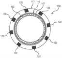
图1B是根据本文所示出并描述的一个或多个实施方案的不透射线的支架移植物的前视图的说明性描绘;Figure IB is an illustrative depiction of a front view of a radiopaque stent-graft, according to one or more embodiments shown and described herein;
图1C是根据本文所示出并描述的一个或多个实施方案的包括任选的密封剂层的不透射线的支架移植物的侧视图的说明性描绘;Figure 1C is an illustrative depiction of a side view of a radiopaque stent-graft including an optional sealant layer, according to one or more embodiments shown and described herein;
图1D是根据本文所示出并描述的一个或多个实施方案的包括任选的密封剂层的不透射线的支架移植物的前视图的说明性描绘;Figure ID is an illustrative depiction of a front view of a radiopaque stent-graft including an optional sealant layer, according to one or more embodiments shown and described herein;
图2是基础支架移植物的侧视图的说明性描绘;Figure 2 is an illustrative depiction of a side view of a base stent-graft;
图3是具有改性外表面的支架移植物的侧视图的说明性描绘;Figure 3 is an illustrative depiction of a side view of a stent-graft having a modified outer surface;
图4是具有粘附层的支架移植物的侧视图的说明性描绘;Figure 4 is an illustrative depiction of a side view of a stent graft with an adhesive layer;
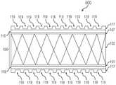
图5是具有蚀刻层的支架移植物的侧视图的说明性描绘;5 is an illustrative depiction of a side view of a stent graft with an etched layer;
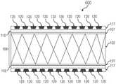
图6是根据本文所示出并描述的一个或多个实施方案的具有带填充槽的蚀刻粘附层的不透射线的支架移植物的侧视图的说明性描绘;6 is an illustrative depiction of a side view of a radiopaque stent-graft having an etched adhesion layer with filled grooves, according to one or more embodiments shown and described herein;
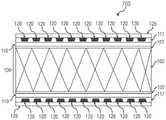
图7是根据本文所示出并描述的一个或多个实施方案的具有任选的密封剂层的不透射线的支架移植物的侧视图的说明性描绘。7 is an illustrative depiction of a side view of a radiopaque stent-graft with an optional sealant layer, according to one or more embodiments shown and described herein.
发明详述Detailed description of the invention
如本文所述的实施方案涉及不透射线的支架移植物和生产不透射线的支架移植物的方法。Embodiments as described herein relate to radiopaque stent-grafts and methods of producing radiopaque stent-grafts.
诸如支架、支架移植物和覆膜支架的可植入假体目前被用来治疗其中血液或其他生物流体流动受限的变窄的(狭窄的)管状身体血管。例如,这类血管可在尿道、食道、胆道、肠、动脉、静脉和外围血管中。在其他治疗之中,可植入假体可被用来支撑开放血管,和增强呼吸系统、生殖系统、胆管或肝管或者任何其他血管中萎陷或狭窄的血管。Implantable prostheses such as stents, stent-grafts, and stent-grafts are currently used to treat narrowed (narrowed) tubular body vessels in which the flow of blood or other biological fluids is restricted. For example, such vessels can be in the urethra, esophagus, biliary tract, bowel, arteries, veins and peripheral blood vessels. Among other treatments, implantable prostheses may be used to support open blood vessels, and to augment collapsed or narrowed blood vessels in the respiratory, reproductive, bile or hepatic ducts, or any other blood vessel.
在常规治疗程序法中,可通过将含有可植入假体的约束构件(即导管)引导至身体血管内的治疗位点,将可植入假体植入身体。为了在部署期间使可植入假体位于身体血管内,医生一般将利用使用X射线的荧光镜使可植入假体或约束构件上的不透射线标志物可视化。然而,如果不透射线标志物位于约束构件上,并且移除了约束构件,则不能确认可植入假体的正确放置。因此,为了通过荧光检查来植入假体,可植入假体的一些部分应优选是不透射线的。In a conventional therapeutic procedure, an implantable prosthesis may be implanted in the body by guiding a constraining member (ie, a catheter) containing the implantable prosthesis to a treatment site within a blood vessel of the body. To position the implantable prosthesis within the body's blood vessels during deployment, the physician will typically visualize radiopaque markers on the implantable prosthesis or constraining member using fluoroscopy using X-rays. However, if the radiopaque marker is located on the constraining member, and the constraining member is removed, correct placement of the implantable prosthesis cannot be confirmed. Therefore, in order to implant the prosthesis by fluoroscopy, some parts of the implantable prosthesis should preferably be radiopaque.
然而,将不透射线标志物直接掺合入可植入假体可能使器械损坏。根据常规方法,为了将不透射线标志物掺合入器械(即通过在器械的表面蚀刻槽以接收不透射线标志物),对器械表面的改性可能使器械的性质受损。例如,这类常规方法可造成器械渗漏。一个实例包括支架移植物。However, incorporation of radiopaque markers directly into implantable prostheses can damage the device. According to conventional methods, modification of the device surface may compromise the properties of the device in order to incorporate radiopaque markers into the device (ie, by etching grooves in the surface of the device to receive the radiopaque markers). For example, such conventional methods can result in leaky devices. One example includes stent grafts.
支架移植物指的是与血管移植物组合使用的支架,血管移植物提供了能够维持相对于血管壁的配合的假体。支架移植物也可代替支架使用以防止再狭窄,再狭窄在平滑肌细胞和其他组织可生长穿过支架的网状开孔的情况下可能发生。支架移植物通常可包括包封在聚四氟乙烯(PTFE)内的可膨胀支架。因为PTFE具有生物相容性、轻质、多孔且易于活细胞定殖而常用。如本文中所使用的,“生物相容性”意指在置于哺乳动物身体内时造成很少或无免疫原性反应。虽然使用包含PTFE的支架移植物有优点,但PTFE表面自身是非反应性的。因此,将不透射线标志物附接于常规支架移植物的PTFE表面而不损坏支架移植物可能是几乎不可能的。Stent-graft refers to a stent used in combination with a vascular graft that provides a prosthesis capable of maintaining a fit relative to the vessel wall. Stent grafts may also be used in place of stents to prevent restenosis, which can occur when smooth muscle cells and other tissue can grow through the mesh openings of the stent. Stent-grafts typically may include an expandable stent encapsulated within polytetrafluoroethylene (PTFE). PTFE is commonly used because it is biocompatible, lightweight, porous, and readily colonized by living cells. As used herein, "biocompatible" means causing little or no immunogenic response when placed in the body of a mammal. While there are advantages to using stent-grafts comprising PTFE, the PTFE surface itself is non-reactive. Therefore, it may be nearly impossible to attach radiopaque markers to the PTFE surface of conventional stent-grafts without damaging the stent-grafts.
因此,需要不透射线的支架移植物和制作不透射线的支架移植物的改进方法。此外,需要可对支架移植物造成很少损坏或无损坏的制作不透射线的支架移植物的方法。本文所述不透射线的支架移植物的实施方案可适用于在治疗程序期间确认支架在血管内的正确放置。本文所述不透射线的支架移植物的准确可视化可使程序的侵入性降至最低,并允许在跟踪检查期间另外的可视化。Accordingly, there is a need for radiopaque stent-grafts and improved methods of making radiopaque stent-grafts. Additionally, there is a need for methods of making radiopaque stent-grafts that cause little or no damage to the stent-graft. Embodiments of the radiopaque stent-grafts described herein are useful for confirming proper placement of the stent within a vessel during a treatment procedure. Accurate visualization of the radiopaque stent-grafts described herein can minimize the invasiveness of the procedure and allow for additional visualization during follow-up examinations.
不透射线的支架移植物radiopaque stent graft
现将描述不透射线的支架移植物的实施方案。图1A和图1B分别是根据本文所示出并描述的一个或多个实施方案的不透射线的支架移植物100的侧视图和前视图的说明性描绘。图1C和图1D分别是根据本文所示出并描述的一个或多个实施方案的具有任选的密封剂层的不透射线的支架移植物100的侧视图和前视图的说明性描绘。Embodiments of radiopaque stent-grafts will now be described. 1A and 1B are illustrative depictions of side and front views, respectively, of a radiopaque stent-
参考图1A-1D和图2,在实施方案中,不透射线的支架移植物100可包括具有官能化表面107的支架移植物106。支架移植物106可由诸如图2中所示的基础支架移植物101产生,基础支架移植物101具有包封在血管移植物105内的可膨胀支架102。Referring to FIGS. 1A-1D and FIG. 2 , in an embodiment, a radiopaque stent-
仍参考图2,基础支架移植物101的可膨胀支架102可为气囊膨胀或自膨胀支架。可膨胀支架102可通过各种制造方法来制作,包括形成线材和机械加工中空管。机械加工方法可包括光化学蚀刻、激光切割、冲压、冲孔或其他材料去除法中的一者或多者。其他制造方法可包括真空或化学沉积材料,或者形成经机械加工平整材料的管。Still referring to FIG. 2 , the
在实施方案中,基础支架移植物101的可膨胀支架102可被配置为连接到一起的一系列环以形成网格状框架,由此界定管状框架。在实施方案中,一系列环可为或可不为基本上相同的。在实施方案中,环可被布置为圆形构造、螺旋构造或螺旋和圆形框架的组合。在实施方案中,一系列环在相邻环之间可具有或可不具有相连的联接。在相邻环之间未利用相连联接的实施方案中,一系列环可由一个环与下一个环之间的直接连接而连接。一系列环可彼此相邻放置以便维持每个环之间适当的纵向间隔。In an embodiment, the
基础支架移植物101的可膨胀支架102可包含生物相容性金属合金。生物相容性金属合金的实例可包括不锈钢、Nitinol或Elgiloy。在实施方案中,Nitinol的形状记忆特性可允许基础支架移植物101的可膨胀支架102在正常体温下置于管状身体血管中时自膨胀。The
在实施方案中,基础支架移植物101的血管移植物105可包含:PTFE,聚氯乙烯(PVC),聚对苯二甲酸乙二醇酯(PET),聚乙烯,尼龙,PEBAX(即聚醚和聚酰胺的共聚物),聚苯乙烯(PS),聚对苯二甲酸乙二醇酯(PETP),涤纶网增强的脐带组织,牛胶原,聚酯针织胶原,经编针织聚酯浸胶原,聚氨酯(可以商标“Vectra R”购得),或本领域普通技术人员将明白的各种其他合适的材料。在实施方案中,基础支架移植物101可为包封在PTFE内的自膨胀支架。在实施方案中,基础支架移植物101可为包封在PTFE内的自膨胀Nitinol支架。一个实例在商业上被称为
在实施方案中,血管移植物105的厚度(“壁厚”)可提供给基础支架移植物101可挠性以辅助在植入期间不透射线的支架移植物100的操纵。在实施方案中,血管移植物105的壁厚可影响不透射线的支架移植物100和相关联递送系统的整体尺寸。例如,在实施方案中,相对较薄的壁厚可允许制造相对较小的不透射线的支架移植物100,其可使用基于相对较小尺寸导管的递送系统来递送。另外,壁厚可影响不透射线的支架移植物100的结构完整性。例如,薄的壁厚可在植入期间易于结构劣化或扭结。In an embodiment, the thickness ("wall thickness") of the
在实施方案中,血管移植物105的壁厚可为约50微米至约1000微米。在实施方案中,血管移植物105的壁厚可为约50微米至约800微米,约50微米至约600微米,约50微米至约400微米,约50微米至约200微米,约50微米至约100微米,约100微米至约1000微米,约100微米至约800微米,约100微米至约600微米,约100微米至约400微米,约100微米至约200微米,约200微米至约1000微米,约200微米至约800微米,约200微米至约600微米,约200微米至约400微米,约400微米至约1000微米,约400微米至约800微米,约400微米至约600微米,约600微米至约1000微米,约600微米至约800微米,或约800微米至约1000微米。In an embodiment, the wall thickness of the
现在参考图3-4,不透射线的支架移植物100可包括官能化表面107,即经受了降低血管移植物105的外表面的表面自由能的表面改性的表面,之后施用粘附层115(如图4中所示和下文更详细论述的)。如将在下文更详细描述的,表面改性可包括对血管移植物105的外表面的等离子体处理。Referring now to FIGS. 3-4 , the radiopaque stent-
现在参考图5-6,在实施方案中,蚀刻层117还可包括一个或多个槽119,其中“槽”可指代通过蚀刻粘附层115形成的储库或表面特征。随后将一个或多个不透射线标志物施用于一个或多个槽119,由此产生一个或多个填充槽120。不透射线标志物可填充蚀刻层117中的储库或表面特征的至少一部分。因此,包含一个或多个不透射线标志物的一个或多个填充槽120允许在植入期间不透射线的支架移植物100的荧光检查可视化。在实施方案中,一个或多个不透射线标志物具有并入其中的不透射线的特征,其可被用作通过荧光检查定位的可视标志物。Referring now to FIGS. 5-6 , in an embodiment,
现在参考图7,因为不透射线的支架移植物100可在实施期间通过荧光检查可视,可防止目前公开的不透射线的支架移植物被部署于非预期位置。另外,与多次部署尝试或重新定位相关联的侵入性可被降低或消除。在实施方案中,不透射线的支架移植物100的可视化可在治疗期间被用于植入和跟踪检查二者。Referring now to FIG. 7, because the radiopaque stent-
在一些实施方案中,不透射线的支架移植物100可包括密封剂层125,其包括涂布在一个或多个填充槽120上的胶粘剂。In some embodiments, the radiopaque stent-
生产不透射线的支架移植物的方法Method of producing a radiopaque stent-graft
现将描述生产不透射线的可植入假体的方法的实施方案。在实施方案中,所公开方法可产生如在本发明中先前所述的不透射线的支架移植物。虽然以下方法将被描述为生产不透射线的支架移植物的方法,但应理解也涵盖了其他可植入假体。Embodiments of methods of producing a radiopaque implantable prosthesis will now be described. In embodiments, the disclosed methods can produce radiopaque stent-grafts as previously described in this disclosure. While the following methods will be described as methods of producing radiopaque stent-grafts, it should be understood that other implantable prostheses are also contemplated.
现在大体上参考图2-7,生产不透射线的支架移植物100的方法的实施方案可包括:使基础支架移植物101的血管移植物105的外表面官能化以产生具有官能化表面107的支架移植物106;在官能化表面107上设置连结层110;在连结层110上设置粘附层115;在粘附层115中蚀刻一个或多个槽119;使一个或多个槽119官能化;并且在一个或多个槽119中布置不透射线标志物以产生一个或多个填充槽120,并由此产生不透射线的支架移植物100。Referring now generally to FIGS. 2-7 , an embodiment of a method of producing a radiopaque stent-
如先前所述,图2是基础支架移植物101的侧视图的说明性描绘。在实施方案中,基础支架移植物101包括具有外表面的血管移植物105。血管移植物105的外表面可为惰性的。在实施方案中,基础支架移植物101的血管移植物105的外表面可经受示例性表面改性过程以使血管移植物105的外表面官能化,并由此产生如图3中所示具有官能化表面107的支架移植物106。参考图2-3,表面改性可提高血管移植物105的外表面的官能性,从而产生可将一个或多个层施用于支架移植物106的官能化表面107,如下文所述。As previously noted, FIG. 2 is an illustrative depiction of a side view of base stent-
回顾图1A-1D,且如先前所述,不透射线的支架移植物100可包括官能化表面107,即经受了表面改性的表面。再次参考图2-3,在实施方案中,表面改性可包括对基础支架移植物101的血管移植物105的外表面的等离子体处理。在实施方案中,血管移植物105的外表面经受示例性等离子体处理过程以使血管移植物105的外表面官能化,并由此产生官能化表面107。如先前所述,在实施方案中,血管移植物105可由聚合物材料形成。在示例性实施方案中,血管移植物105可由包含以下的聚合物材料形成:聚四氟乙烯(PTFE),聚氯乙烯(PVC),聚对苯二甲酸乙二醇酯(PET),聚乙烯,尼龙,PEBAX(即聚醚和聚酰胺的共聚物),聚苯乙烯(PS),聚对苯二甲酸乙二醇酯(PETP),或如本领域普通技术人员将明白的各种其他合适的材料。等离子体处理过程可提高血管移植物105的外表面的官能性,由此产生官能化表面107使得可将一个或多个层施用于支架移植物106。Referring back to FIGS. 1A-1D , and as previously described, the radiopaque stent-
仍参考图2-3,在实施方案中,等离子体处理过程被配置成沿血管移植物105的外表面和/或血管移植物105的其他部分使基础支架移植物101官能化。通过在将粘附层115(如随后描述的图4中所示)施用于基础支架移植物101上之前使血管移植物105的外表面官能化,可操作等离子体处理过程使血管移植物105的外表面的材料性质改性,以由此提供粘附层115与官能化表面107之间改进的相互作用。例如,用等离子体处理过程处理血管移植物105的外表面允许将一个或多个不透射线标志物置于支架移植物106上(经由粘附层)而不损坏支架移植物106。Still referring to FIGS. 2-3 , in an embodiment, the plasma treatment process is configured to functionalize the base stent-
仍参考图2-3,在示例性使用中,基础支架移植物101的至少一部分被置于等离子体腔室(未示出)内以按照等离子体处理过程处理。在本实例中,基础支架移植物101被置于等离子体腔室内,使得由等离子体处理过程处理血管移植物105的外表面。虽然在本实施方案中描述了处理血管移植物105的外表面,但应理解基础支架移植物101和/或其他合适的可植入假体的其他不同部分可用本发明的等离子体处理过程处理,如本领域普通技术人员将明白的。在基础支架移植物101置于其中的情况下,通过在腔室内生成所需真空开始等离子体处理过程。在这种情况下,血管移植物105的外表面经受腔室内生成的真空气氛。在等离子体处理期间,腔室内所用温度和压力可取决于基础支架移植物101的材料。例如,过高的温度可破坏基础支架移植物101的材料。在实施方案中,腔室内的温度可为25℃至50℃、20℃至40℃、20℃至30℃、30℃至50℃、30℃至40℃或40℃至50℃。Still referring to FIGS. 2-3 , in an exemplary use, at least a portion of base stent-
利用腔室内维持的真空压力,血管移植物105的外表面的聚合物材料暴露于由耦接至等离子体腔室的气体源(未示出)供应的气体。在实施方案中,血管移植物105的外表面可暴露于由气体源供应的氙、氩、氟、氟碳气体混合物、氙/氧气体混合物或其他合适的气体混合物。在具定实施方案中,血管移植物105的外表面可暴露于由气体源供应的氙、氩或氙/氧气体混合物。取决于供应气体的类型,可操作气体源由传输入腔室的气体生成离子(即氟化离子)和自由基。在一些实施方案中,可操作气体源由传输入腔室的氟或氟碳气体生成含氟离子(即氟化离子)和自由基。仅以举例的方式,可由气体源传输的气体可包含:四氟甲烷(CF4),六氟乙烷(C2F6),二氟化氙(XeF2),氟(F2),五氟氯乙烷(CF3CCIF2),六氟化硫(SF6),和如本领域普通技术人员将明白的其他合适的气体。混合物释放入腔室使血管移植物105的外表面以预定流量经受气体预定的持续时间。With the vacuum pressure maintained within the chamber, the polymeric material of the outer surface of the
然后,在实施方案中,与腔室流体连通的等离子体发生器(未示出)被激活由此将等离子体释放入容器,并由此使血管移植物105的外表面暴露于等离子体。作为仅说明性实例,等离子体发生器可包含:电弧放电器,介电阻挡放电器,火花放电器,电阻阻挡放电器,射频激发,微波频率激发,和如本领域普通技术人员将明白的其他合适的发生器。Then, in an embodiment, a plasma generator (not shown) in fluid communication with the chamber is activated thereby releasing plasma into the vessel and thereby exposing the outer surface of the
血管移植物105的外表面可用来源于等离子体发生器的等离子体处理,使得等离子体以预定流量与血管移植物105的外表面的聚合物材料相互作用。在实施方案中,生成的等离子体包含离子和自由基。等离子体离子注入步骤可包括首先从等离子体发生器提取离子,并随后选择所需离子经由等离子体发生器的磁场(未示出)经过加速柱传输。在这种情况下,由磁场选择的离子被驱使至血管移植物105的外表面的聚合物材料中,使得离子被有效注入血管移植物105的外表面,由此产生官能化表面107。血管移植物105的外表面的聚合物材料的氢原子同时被注入其上的离子物类替代。The outer surface of the
在示例性实施方案中,血管移植物105的外表面可用来源于等离子体发生器的等离子体氟化,使得等离子体以预定流量与血管移植物105的外表面的聚合物材料相互作用。在本实例中,生成的等离子体包含含氟离子和自由基。等离子体离子注入步骤可包括首先从等离子体发生器提取含氟离子,并随后选择所需离子经由等离子体发生器的磁场(未示出)经过加速柱传输。在这种情况下,由磁场选择的含氟离子被驱使至血管移植物105的外表面的聚合物材料中,使得离子被有效注入血管移植物105的外表面。血管移植物105的外表面的聚合物材料的氢原子同时被注入其上的氟化物类替代。In an exemplary embodiment, the outer surface of the
然后,在实施方案中,用等离子体连续处理容纳在等离子体腔室内的基础支架移植物101的部分(即血管移植物105的外表面)预定的持续时间,由此沿支架移植物106形成官能化表面107。一旦血管移植物105的外表面已暴露于等离子体预定的持续时间,产生了官能化表面107,可结束等离子体处理过程。Then, in an embodiment, the portion of the base stent-
参考图3,在实施方案中,在产生官能化表面107后,可在官能化表面107上设置连结层110。如本文中所使用的,术语“连结层”指的是将两个层粘附到一起的层。例如,连结层可将极性材料粘合于不包括极性材料的一个或多个层。在实施方案中,连结层可包括能够使官能化表面107粘附于随后施用的粘附层115(在下文更详细描述)的任何材料。在一些实施方案中,连结层110可为硅烷层。Referring to FIG. 3 , in an embodiment, after the
在实施方案中,连结层110的施用可通过本领域已知的各种方法来施用。例如,可通过本领域已知的各种涂布方法将连结层110涂布于官能化表面107上,例如通过浸渍、喷雾、喷墨印刷、其他方法或组合。在其他实施方案中,连结层110可通过等离子体处理过程施用于官能化表面107上。可基于连结层110的材料选择等离子体处理过程。在一些实施方案中,将连结层110施用于官能化表面107上的等离子体处理法可不利用等离子体腔室内的电场。在实施方案中,可通过在与先前所述相同的等离子体腔室中进行的等离子体处理过程,将连结层110施用于官能化表面107上。替代地或另外,可在先前所述等离子体腔室的外部或在不同的等离子体腔室中将连结层110施用于官能化表面107上。将连结层110施用于官能化表面107上的实施方案还可包括涂布法和等离子体处理法的组合。In embodiments, the application of the
如图3中所见,设置于官能化表面107上的连结层110可相对最小,并且包括沿官能化表面107的表面区域大致上均匀的分布。仅以举例的方式,植入到官能化表面107上的连结层110的厚度小于一微米。在实施方案中,连结层110可为10埃


在产生官能化表面107的等离子体处理过程完成且设置于其上的连结层110完成的情况下,处理过程有效形成了可在其上设置粘附层的表面。如鉴于本文中的教导应理解的,通过应用适当的气体类型、气体流量、处理时间和发生器功率,可在等离子体处理过程中实现最优结果。With the plasma treatment process to produce
利用设置于官能化表面107上的连结层110的最小厚度,粘附层115被设置于连结层110上,如图4中所见。在实施方案中,粘附层115允许将一个或多个不透射线标志物置于支架移植物106上(经由粘附层)而不损坏支架移植物106的血管移植物。With the minimum thickness of the
粘附层115可包括聚合物。粘附层115的特别合适的聚合物包括避免了不期望的身体组织刺激的生物相容性聚合物。示例性聚合物包括由环脂族单体或芳族单体形成的聚合物。环脂族单体的实例包括烷基环己烷,诸如甲基环己烷。芳族单体的实例包括烷基苯,诸如甲苯和二甲苯。在一些实施方案中,中间层可为例如聚对二甲苯,诸如派瑞林C、派瑞林N、派瑞林D、派瑞林X、派瑞林AF-4、派瑞林SF、派瑞林HT、派瑞林VT-4(派瑞林F)、派瑞林CF、派瑞林A或派瑞林AM。所选派瑞林的结构提供如下:The

其他聚合物可存在于粘附层115中。这类其他聚合物的实例包括例如:聚烯烃,聚异丁烯,乙烯-α-烯烃共聚物,丙烯酸系聚合物和共聚物,聚氯乙烯,聚乙烯基甲基醚,聚偏二氟乙烯和聚偏二氯乙烯,聚丙烯腈,聚乙烯酮,聚苯乙烯,聚乙酸乙烯酯,乙烯-甲基丙烯酸甲酯共聚物,丙烯腈-苯乙烯共聚物,ABS树脂,尼龙12和其嵌段共聚物,聚已酸内酯,聚氧化甲烯,聚醚,环氧树脂,聚氨酯,三乙酸人造丝,纤维素,乙酸纤维素,丁酸纤维素,赛璐玢,硝酸纤维素,丙酸纤维素,纤维素醚,羧甲基纤维素,壳多糖,聚乳酸,聚乙醇酸,聚乳酸-聚氧化乙烯共聚物,聚乙二醇,聚丙二醇,聚乙烯醇,以及它们的混合物和嵌段共聚物。在实施方案中,其他聚合物可选自具有低表面自由能的聚合物。Other polymers may be present in the
不意图受理论约束,认为包括诸如像派瑞林的某些聚合物材料的粘附层可经由连结层110粘附于官能化表面107,并由此产生可在其上将一个或多个不透射线标志物施用于支架移植物106的层。Without intending to be bound by theory, it is believed that an adhesive layer comprising certain polymeric materials such as parylene can adhere to the
因为根据实施方案的可植入假体、特别是例如支架移植物经受了机械操纵、即膨胀和收缩,可用于粘附层115中的聚合物的另外的实例可包括弹性聚合物,诸如有机硅(例如聚硅氧烷和取代的聚硅氧烷)、聚氨酯、热塑性弹性体、乙烯乙酸乙烯酯共聚物、聚烯烃弹性体和EPDM橡胶。因为这些聚合物的弹性特性,当这些聚合物被包括在粘附层115中时,在可植入假体经受力或应力时不透射线标志物对粘附层115的表面和最终对可植入假体的粘附可增加。Since implantable prostheses according to embodiments, in particular e.g. stent-grafts, are subject to mechanical manipulation, i.e. expansion and contraction, further examples of polymers that may be used in the
粘附层115可包含一种或多种其他组分以便维持一个或多个不透射线标志物和/或密封剂层对可植入假体的粘附和完整性,来促进在运输和部署期间不透射线标志物和添加剂组分在身体血管内治疗位点处的粘附,或这些益处的组合。The
在实施方案中,粘附层115的厚度可为1微米至5微米,1微米至4微米,1微米至3微米,1微米至2微米,2微米至5微米,2微米至4微米,2微米至3微米,3微米至5微米,3微米至4微米,或4微米至5微米。In an embodiment, the thickness of the
现在参考图5,在实施方案中,可在粘附层115中蚀刻一个或多个槽由此产生蚀刻层117。如本文中所使用的,“蚀刻”意指在粘附层115的表面中创建表面改性。蚀刻法可被用来在粘附层115中蚀刻一个或多个槽119以产生蚀刻层117。一个或多个槽119可允许不透射线标志物在粘附层115内的粘附改进。Referring now to FIG. 5 , in an embodiment, one or more grooves may be etched in
考虑到不同的蚀刻方法,可包括利用化学法、机械法、激光(器)、其他蚀刻法和它们的组合。在实施方案中,蚀刻可包括利用溶剂选择性溶解粘附层115的表面。在实施方案中,蚀刻可包括利用激光(器)。在其他实施方案中,激光(器)可为准分子激光(器)。在实施方案中,蚀刻可包括利用诸如刀片或剪切机的机械蚀刻装置。具体蚀刻方法的选择可取决于总过程的所需效率和/或方法的所需精确性。在具体实施方案中,可选择准分子激光(器)蚀刻以产生具有精确尺寸的一个或多个槽。Different etching methods are contemplated, including utilizing chemical methods, mechanical methods, laser(s), other etching methods, and combinations thereof. In an embodiment, etching may include selectively dissolving the surface of the
一个或多个槽119的尺寸和数量可取决于不透射线的支架移植物100的所需射线不透性。在一些实施方案中,可需要仅一个槽。在其他实施方案中,可需要一个或多个另外的槽。在实施方案中,可沿粘附层115的表面以任何定向或任何图案蚀刻一个或多个槽。例如,在实施方案中,可在径向、纵向或两个方向上蚀刻一个或多个槽119。The size and number of the one or
仍参考图5,在实施方案中,蚀刻层117可经受第二等离子体处理过程。第二等离子体处理过程可允许一个或多个不透射线标志物于蚀刻层117上的粘附(经由一个或多个槽119)得到改进。如先前说明的,蚀刻层117由聚合物形成。对蚀刻层117的聚合物材料施用第二等离子体处理过程可使蚀刻层117官能化。Still referring to FIG. 5 , in an embodiment, the
在本实例中,第二处理过程可被配置成改进蚀刻层117的粘附性质。通过在一个或多个槽119中施用一个或多个不透射线标志物之前使蚀刻层117的表面官能化,第二等离子体处理过程可使蚀刻层117的材料性质改性,以由此提供一个或多个不透射线标志物与蚀刻层117之间改进的相互作用。例如,用第二等离子体处理过程处理蚀刻层117的表面可允许一个或多个不透射线标志物粘附于蚀刻层117。最终,可操作第二等离子体处理过程以通过防止损坏支架移植物106的方法来提供不透射线的支架移植物100。In this example, the second treatment process may be configured to improve the adhesion properties of the
在示例性使用中,蚀刻层117的至少一部分可被置于第二等离子体腔室(未示出)内,以按照第二等离子体处理过程处理。在本实例中,蚀刻层117的至少一部分可被置于等离子体腔室内,使得用第二等离子体处理过程处理蚀刻层117。在蚀刻层117的至少一部分置于其中的情况下,可通过在第二等离子体腔室内生成所需真空开始第二处理过程。在这种情况下,蚀刻层117可经受在腔室内生成的真空气氛。腔室内的温度可取决于蚀刻层117的材料。在实施方案中,腔室内的温度可为25℃至50℃、20℃至40℃、20℃至30℃、30℃至50℃、30℃至40℃或40℃至50℃。In an exemplary use, at least a portion of the etched
利用腔室内维持的真空压力,蚀刻层117的聚合物材料暴露于由耦接至等离子体室的气体源(未示出)供应的气体。在实施方案中,蚀刻层117可暴露于由气体源供应的氙、氩、氟、氟碳气体混合物、氙/氧气体混合物、丙烯酸酯气体或其他合适的气体混合物。在具体实施方案中,蚀刻层117可暴露于由气体源供应的氙和丙烯酸酯气体混合物。取决于供应气体的类型,可操作气体源产生来自传输入腔室的气体的离子(即氟化离子)和自由基。在一些实施方案中,可操作气体源以由传输入腔室的氟或氟碳气体生成含氟离子(即氟化离子)和自由基。仅以举例的方式,可由气体源传输的气体可包含:四氟甲烷(CF4),六氟乙烷(C2F6),二氟化氙(XeF2),氟(F2),五氟氯乙烷(CF3CCIF2),六氟化硫(SF6),和如本领域普通技术人员将明白的其他合适的气体。混合物释放入腔室使蚀刻层117以预定流量经受气体预定的持续时间。With the vacuum pressure maintained within the chamber, the polymer material of the
然后,在实施方案中,与腔室流体连通的第二等离子体发生器(未示出)可被激活由此将等离子体释放入容器,并由此使蚀刻层117暴露于等离子体。作为仅说明性实例,第二等离子体发生器可包含:电弧放电器,介电阻挡放电器,火花放电器,电阻阻挡放电器,射频激发,微波频率激发,和如本领域普通技术人员将明白的其他合适的发生器。Then, in an embodiment, a second plasma generator (not shown) in fluid communication with the chamber can be activated thereby releasing plasma into the vessel and thereby exposing the
蚀刻层117可用来源于第二等离子体发生器的等离子体氟化,使得等离子体以预定流量与蚀刻层117的聚合物材料相互作用。在本实例中,生成的等离子体包含离子和自由基。等离子体离子注入步骤可包括首先从第二等离子体发生器提取离子,并随后选择所需离子经由第二等离子体发生器的磁场(未示出)经过加速柱传输。在这种情况下,由磁场选择的离子被驱使至蚀刻层117的聚合物材料中,使得离子被有效注入蚀刻层117。蚀刻层117的聚合物材料的氢原子同时被注入其上的离子物类替代。The
然后,在实施方案中,容纳在第二等离子体腔室内的蚀刻层117的部分可用等离子体连续处理预定的持续时间,由此沿蚀刻层117形成官能化表面。一旦蚀刻层117已暴露于等离子体预定的持续时间,产生了包含植入其上的等离子体层(未示出)的蚀刻层117,由此使蚀刻层117官能化,可结束第二等离子体处理过程。Then, in an embodiment, the portion of the etched
在实施方案中,官能化等离子体层(未示出)可植入于蚀刻层117上,其可相对最小且可包括沿蚀刻层117的表面区域大致上均匀的分布。仅以举例的方式,植入于蚀刻层117上的等离子体层的厚度可小于一微米。在蚀刻层117的聚合物表面与施用于其上的等离子体层的反应完成的情况下,第二等离子体处理过程有效形成了在其上可以改进的粘附施用一个或多个不透射线标志物的官能化表面。如鉴于本文中的教导应理解的,通过应用适当的气体类型、气体流量、处理时间和发生器功率,可在第二等离子体处理过程中实现最优结果。利用施用于蚀刻层117上的等离子体层的最小厚度,可在蚀刻层117的一个或多个槽119中施用一个或多个不透射线标志物。In an embodiment, a functionalized plasma layer (not shown) may be implanted on the
现在参考图6,在实施方案中,不透射线标志物可被置于一个或多个槽119的每一者中,从而产生填充槽120,并由此产生不透射线的支架移植物100。不透射线标志物可填充蚀刻层117中一个或多个槽119的至少一部分。因此,包含一个或多个不透射线标志物的一个或多个填充槽120允许在植入期间不透射线的支架移植物100的荧光检查可视化。在实施方案中,一个或多个不透射线标志物具有并入其中的不透射线的特征,其可被用作通过荧光检查定位的可视标志物。Referring now to FIG. 6 , in an embodiment, a radiopaque marker may be placed in each of the one or
不透射线标志物可包含不透射线材料。例如,不透射线材料可包括:聚合物,金,铂-铱合金,碱式碳酸铋,硫酸钡,氯氧化铋,三氧化二铋,钨,组合,和本领域技术人员已知的各种其他不透射线材料。A radiopaque marker may comprise a radiopaque material. For example, radiopaque materials may include: polymers, gold, platinum-iridium alloys, bismuth subcarbonate, barium sulfate, bismuth oxychloride, bismuth trioxide, tungsten, combinations, and various others known to those skilled in the art. Other radiopaque materials.
现在参考图7,在不透射线的支架移植物100的实施方案中,具有填充槽120的蚀刻层117可任选地用胶粘剂涂布,从而产生密封剂层125。密封剂层125可将一个或多个不透射线标志物包封在一个或多个填充槽120内,以使一个或多个不透射线标志物密封在蚀刻层117的一个或多个填充槽120内。在实施方案中,密封剂层125可将一个或多个不透射线标志物完全包封在一个或多个填充槽120内,以防止一个或多个不透射线标志物暴露于周围环境,实现了安全性。Referring now to FIG. 7 , in an embodiment of a radiopaque stent-
密封剂层125可包含已涂布于具有填充槽120的蚀刻层117上的胶粘剂。所利用胶粘剂可基于上文所选不透射线材料和包括生物相容性的其他性质来选择。在实施方案中,用来产生密封剂层125的胶粘剂可包括柔性丙烯酸酯胶粘剂。The
胶粘剂可通过本领域已知的各种涂布方法涂布于具有填充槽120的蚀刻层117上。在实施方案中,胶粘剂可通过浸渍、喷雾或其他方法涂布于具有填充槽120的蚀刻层117上。在实施方案中,方法可进一步包括使胶粘剂固化以形成密封剂层125。在实施方案中,固化胶粘剂可包括使胶粘剂暴露于由紫外光源(未示出)发出的紫外光。在实施方案中,胶粘剂可以足够使胶粘剂完全固化的强度和持续时间暴露于紫外光,并由此产生密封剂层125。在其他实施方案中,可例如施用一个或多个另外的层以改进不透射线的支架移植物100的生物相容性。The adhesive can be coated on the etched
使用不透射线的支架移植物的治疗方法Treatment with radiopaque stent-grafts
现将描述利用本文所述的不透射线的支架移植物的治疗方法的实施方案。Embodiments of methods of treatment utilizing the radiopaque stent-grafts described herein will now be described.
在实施方案中,不透射线的支架移植物100可经由哺乳动物身体上的小切口递送。在实施方案中,不透射线的支架移植物100可经由约束构件递送至受损或患病位点(治疗位点)。约束构件可包括导管或护套。在实施方案中,可将约束构件和不透射线的支架移植物100一起插入小切口,经过身体血管引导至治疗位点,并通过移除约束构件部署。在实施方案中,一旦置于治疗位点并移除约束构件后,不透射线的支架移植物100可随后在正常体温下自膨胀。In an embodiment, radiopaque stent-
为了将不透射线的支架移植物100导向治疗位点的精确位置,可借助X射线使用荧光镜使不透射线的支架移植物100的不透射线标志物可视化。在实施方案中,不透射线的支架移植物100可被用来确认在身体血管内的正确放置。不透射线的支架移植物100可被用来可视化地证实不透射线的支架移植物100的定向,以判定不透射线的支架移植物100是否位置不当、扭曲或扭结。利用本文所述的不透射线的支架移植物100可降低不透射线的支架移植物100部署在非预期位置的风险,这样的部署可能导致即时创伤。利用本文所述的不透射线的支架移植物100可使与多次部署尝试和约束构件重新定位相关联的侵入性提高的风险降低。In order to direct the radiopaque stent-
现应理解如本文所述的实施方案涉及治疗身体血管的系统、方法和导管。具体而言,如本文所述的实施方案包括可允许可视化的不透射线的支架移植物,并因此提供最低程度侵入性的治疗方法。It should now be understood that embodiments as described herein relate to systems, methods and catheters for treating blood vessels of the body. In particular, embodiments as described herein include radiopaque stent-grafts that allow visualization and thus provide minimally invasive treatment methods.
要注意本文中可利用术语“大致上”和“约”来表示可归因于任何定量比较、值、测量结果或其他描绘的不确定性的固有程度。本文中也利用这些术语来表示定量描绘可从规定基准变化而不导致待解决主题的基本功能改变的程度。It is to be noted that the terms "substantially" and "about" may be utilized herein to indicate the inherent degree of uncertainty attributable to any quantitative comparison, value, measurement, or other depiction. These terms are also utilized herein to indicate the degree to which a quantitative depiction may vary from a stated baseline without resulting in a change in the basic function of the subject matter at issue.
尽管在本文中说明和描述了具体实施方案,但应理解可在不脱离所要求主题的精神和范围的情况下作出各种其他变化和修改。此外,虽然本文中已描述了所要求主题的各种方面,但这类方面不必组合利用。因此,意图随附权利要求书涵盖在所要求主题的范围内的所有这类变化和修改。While particular embodiments have been illustrated and described herein, it should be understood that various other changes and modifications can be made without departing from the spirit and scope of the claimed subject matter. Furthermore, while various aspects of the claimed subject matter have been described herein, such aspects do not necessarily have to be utilized in combination. It is therefore intended that the appended claims cover all such changes and modifications that are within the scope of the claimed subject matter.
Claims (22)
Translated fromChineseApplications Claiming Priority (1)
| Application Number | Priority Date | Filing Date | Title |
|---|---|---|---|
| PCT/US2020/019827WO2021173126A1 (en) | 2020-02-26 | 2020-02-26 | Stent grafts having a radiopaque marker and methods of producing |
Publications (2)
| Publication Number | Publication Date |
|---|---|
| CN115315278Atrue CN115315278A (en) | 2022-11-08 |
| CN115315278B CN115315278B (en) | 2023-10-10 |
Family
ID=70005774
Family Applications (1)
| Application Number | Title | Priority Date | Filing Date |
|---|---|---|---|
| CN202080098911.6AActiveCN115315278B (en) | 2020-02-26 | 2020-02-26 | Stent grafts with radiopaque markers and methods of producing the same |
Country Status (6)
| Country | Link |
|---|---|
| US (1) | US20230091740A1 (en) |
| EP (1) | EP4110415B1 (en) |
| JP (1) | JP7255033B2 (en) |
| CN (1) | CN115315278B (en) |
| CA (1) | CA3173258C (en) |
| WO (1) | WO2021173126A1 (en) |
Citations (12)
| Publication number | Priority date | Publication date | Assignee | Title |
|---|---|---|---|---|
| US20020095205A1 (en)* | 2001-01-12 | 2002-07-18 | Edwin Tarun J. | Encapsulated radiopaque markers |
| US20020103528A1 (en)* | 2000-12-18 | 2002-08-01 | Biotronik Mess-Und Therapiegeraete Gmbh & Co | Method of applying a marker element to an implant and an implant provided with a marker element |
| US20030114918A1 (en)* | 2000-04-28 | 2003-06-19 | Garrison Michi E. | Stent graft assembly and method |
| US6635082B1 (en)* | 2000-12-29 | 2003-10-21 | Advanced Cardiovascular Systems Inc. | Radiopaque stent |
| US20060058867A1 (en)* | 2004-09-15 | 2006-03-16 | Thistle Robert C | Elastomeric radiopaque adhesive composite and prosthesis |
| US20080009938A1 (en)* | 2006-07-07 | 2008-01-10 | Bin Huang | Stent with a radiopaque marker and method for making the same |
| CN102143777A (en)* | 2008-09-05 | 2011-08-03 | C·R·巴德公司 | Balloon with radiopaque adhesive |
| CN103298428A (en)* | 2010-11-16 | 2013-09-11 | W.L.戈尔及同仁股份有限公司 | Devices and methods for in situ fenestration of a stent-graft at the site of a branch vessel |
| US20130345793A1 (en)* | 2012-06-26 | 2013-12-26 | Stephen Pacetti | Implantable prosthesis with hollow struts and passivating coating, and method of making same |
| CN104053457A (en)* | 2011-08-19 | 2014-09-17 | 先进生物假体表面有限公司 | Grooved drug-eluting medical devices and method of making same |
| CN104918585A (en)* | 2012-10-25 | 2015-09-16 | 动脉再造技术股份有限公司 | Radiopaque marker for bioresorbable stents |
| CN109803607A (en)* | 2016-06-13 | 2019-05-24 | 主动脉公司 | For marking and/or reinforcing the systems, devices and methods to open a window in prothesis implant body |
Family Cites Families (6)
| Publication number | Priority date | Publication date | Assignee | Title |
|---|---|---|---|---|
| US5824042A (en)* | 1996-04-05 | 1998-10-20 | Medtronic, Inc. | Endoluminal prostheses having position indicating markers |
| US6361557B1 (en)* | 1999-02-05 | 2002-03-26 | Medtronic Ave, Inc. | Staplebutton radiopaque marker |
| US6312457B1 (en)* | 1999-04-01 | 2001-11-06 | Boston Scientific Corporation | Intraluminal lining |
| US20060121080A1 (en)* | 2002-11-13 | 2006-06-08 | Lye Whye K | Medical devices having nanoporous layers and methods for making the same |
| DE102005039126A1 (en)* | 2005-08-18 | 2007-02-22 | Lothar Sellin | Device, useful for expanding lumen container, comprises paclitaxel and is coated with parylene C and/or aloe (aloe vera) extracts |
| US20140121750A1 (en)* | 2012-10-31 | 2014-05-01 | Cook Medical Technologies Llc | Fixation Process For Nesting Stents |
- 2020
- 2020-02-26EPEP20714392.6Apatent/EP4110415B1/enactiveActive
- 2020-02-26CNCN202080098911.6Apatent/CN115315278B/enactiveActive
- 2020-02-26JPJP2022551275Apatent/JP7255033B2/enactiveActive
- 2020-02-26CACA3173258Apatent/CA3173258C/enactiveActive
- 2020-02-26WOPCT/US2020/019827patent/WO2021173126A1/ennot_activeCeased
- 2020-02-26USUS17/904,516patent/US20230091740A1/enactivePending
Patent Citations (13)
| Publication number | Priority date | Publication date | Assignee | Title |
|---|---|---|---|---|
| US20030114918A1 (en)* | 2000-04-28 | 2003-06-19 | Garrison Michi E. | Stent graft assembly and method |
| US20020103528A1 (en)* | 2000-12-18 | 2002-08-01 | Biotronik Mess-Und Therapiegeraete Gmbh & Co | Method of applying a marker element to an implant and an implant provided with a marker element |
| US6635082B1 (en)* | 2000-12-29 | 2003-10-21 | Advanced Cardiovascular Systems Inc. | Radiopaque stent |
| US20020095205A1 (en)* | 2001-01-12 | 2002-07-18 | Edwin Tarun J. | Encapsulated radiopaque markers |
| US20060058867A1 (en)* | 2004-09-15 | 2006-03-16 | Thistle Robert C | Elastomeric radiopaque adhesive composite and prosthesis |
| US20080009938A1 (en)* | 2006-07-07 | 2008-01-10 | Bin Huang | Stent with a radiopaque marker and method for making the same |
| CN102143777A (en)* | 2008-09-05 | 2011-08-03 | C·R·巴德公司 | Balloon with radiopaque adhesive |
| CN103520824A (en)* | 2008-09-05 | 2014-01-22 | C·R·巴德公司 | Balloon with radiopaque adhesive |
| CN103298428A (en)* | 2010-11-16 | 2013-09-11 | W.L.戈尔及同仁股份有限公司 | Devices and methods for in situ fenestration of a stent-graft at the site of a branch vessel |
| CN104053457A (en)* | 2011-08-19 | 2014-09-17 | 先进生物假体表面有限公司 | Grooved drug-eluting medical devices and method of making same |
| US20130345793A1 (en)* | 2012-06-26 | 2013-12-26 | Stephen Pacetti | Implantable prosthesis with hollow struts and passivating coating, and method of making same |
| CN104918585A (en)* | 2012-10-25 | 2015-09-16 | 动脉再造技术股份有限公司 | Radiopaque marker for bioresorbable stents |
| CN109803607A (en)* | 2016-06-13 | 2019-05-24 | 主动脉公司 | For marking and/or reinforcing the systems, devices and methods to open a window in prothesis implant body |
Non-Patent Citations (1)
| Title |
|---|
| 武欣;谷涌泉;段红永;陈兵;李建新;吴英锋;张淑文;汪忠镐;张建;: "可降解组织工程血管支架成功用于犬股动脉移植", 中国实验动物学报, no. 03* |
Also Published As
| Publication number | Publication date |
|---|---|
| CA3173258A1 (en) | 2021-09-02 |
| WO2021173126A1 (en) | 2021-09-02 |
| CN115315278B (en) | 2023-10-10 |
| US20230091740A1 (en) | 2023-03-23 |
| EP4110415A1 (en) | 2023-01-04 |
| JP2023507672A (en) | 2023-02-24 |
| JP7255033B2 (en) | 2023-04-10 |
| EP4110415C0 (en) | 2023-11-29 |
| CA3173258C (en) | 2023-08-29 |
| EP4110415B1 (en) | 2023-11-29 |
Similar Documents
| Publication | Publication Date | Title |
|---|---|---|
| US6641607B1 (en) | Double tube stent | |
| US6635082B1 (en) | Radiopaque stent | |
| EP2303348B1 (en) | Bioerodible endoprosthesis | |
| JP5204666B2 (en) | Bioerodible endoprosthesis and method for producing the same | |
| ES2635270T3 (en) | Implantable medical devices with fluorinated polymer coatings, and coating methods thereof | |
| US6364856B1 (en) | Medical device with sponge coating for controlled drug release | |
| US7198637B2 (en) | Method and system for stent retention using an adhesive | |
| EP3076899B1 (en) | Length extensible implantable device and methods for making such devices | |
| US20020095205A1 (en) | Encapsulated radiopaque markers | |
| US6958073B2 (en) | Method and system for stent retention using an adhesive | |
| US20080009938A1 (en) | Stent with a radiopaque marker and method for making the same | |
| JP2002505591A (en) | Treatment of aneurysms by applying a sclerosing or softening agent to a sclerosing or softening substance | |
| WO2014152131A1 (en) | Welded stent and stent delivery system | |
| WO2000001322A1 (en) | Medical device with porous surface for controlled drug release and method of making the same | |
| JPH0852221A (en) | Prosthesis in blood vessel with anti-thrombosis coating film | |
| CN115315278B (en) | Stent grafts with radiopaque markers and methods of producing the same | |
| WO2001021106A9 (en) | Radioactive graft or cuff | |
| EP2809370B1 (en) | Negatively charged vascular stent | |
| IE20010685A1 (en) | A removable stent | |
| HK1228724B (en) | Length extensible implantable device and methods for making such devices | |
| HK1228724A1 (en) | Length extensible implantable device and methods for making such devices |
Legal Events
| Date | Code | Title | Description |
|---|---|---|---|
| PB01 | Publication | ||
| PB01 | Publication | ||
| SE01 | Entry into force of request for substantive examination | ||
| SE01 | Entry into force of request for substantive examination | ||
| GR01 | Patent grant | ||
| GR01 | Patent grant |