CN115311976A - STV control-based partition grid scanning method and display panel - Google Patents
STV control-based partition grid scanning method and display panelDownload PDFInfo
- Publication number
- CN115311976A CN115311976ACN202210954049.5ACN202210954049ACN115311976ACN 115311976 ACN115311976 ACN 115311976ACN 202210954049 ACN202210954049 ACN 202210954049ACN 115311976 ACN115311976 ACN 115311976A
- Authority
- CN
- China
- Prior art keywords
- scanning
- stv
- stv signal
- signal line
- lines
- Prior art date
- Legal status (The legal status is an assumption and is not a legal conclusion. Google has not performed a legal analysis and makes no representation as to the accuracy of the status listed.)
- Pending
Links
Images


Classifications
- G—PHYSICS
- G09—EDUCATION; CRYPTOGRAPHY; DISPLAY; ADVERTISING; SEALS
- G09G—ARRANGEMENTS OR CIRCUITS FOR CONTROL OF INDICATING DEVICES USING STATIC MEANS TO PRESENT VARIABLE INFORMATION
- G09G3/00—Control arrangements or circuits, of interest only in connection with visual indicators other than cathode-ray tubes
- G09G3/20—Control arrangements or circuits, of interest only in connection with visual indicators other than cathode-ray tubes for presentation of an assembly of a number of characters, e.g. a page, by composing the assembly by combination of individual elements arranged in a matrix no fixed position being assigned to or needed to be assigned to the individual characters or partial characters
- G09G3/2085—Special arrangements for addressing the individual elements of the matrix, other than by driving respective rows and columns in combination
- G—PHYSICS
- G09—EDUCATION; CRYPTOGRAPHY; DISPLAY; ADVERTISING; SEALS
- G09G—ARRANGEMENTS OR CIRCUITS FOR CONTROL OF INDICATING DEVICES USING STATIC MEANS TO PRESENT VARIABLE INFORMATION
- G09G3/00—Control arrangements or circuits, of interest only in connection with visual indicators other than cathode-ray tubes
- G09G3/20—Control arrangements or circuits, of interest only in connection with visual indicators other than cathode-ray tubes for presentation of an assembly of a number of characters, e.g. a page, by composing the assembly by combination of individual elements arranged in a matrix no fixed position being assigned to or needed to be assigned to the individual characters or partial characters
- G09G3/2007—Display of intermediate tones
- G09G3/2077—Display of intermediate tones by a combination of two or more gradation control methods
- G—PHYSICS
- G09—EDUCATION; CRYPTOGRAPHY; DISPLAY; ADVERTISING; SEALS
- G09G—ARRANGEMENTS OR CIRCUITS FOR CONTROL OF INDICATING DEVICES USING STATIC MEANS TO PRESENT VARIABLE INFORMATION
- G09G2310/00—Command of the display device
- G09G2310/02—Addressing, scanning or driving the display screen or processing steps related thereto
- G09G2310/0264—Details of driving circuits
- G09G2310/0267—Details of drivers for scan electrodes, other than drivers for liquid crystal, plasma or OLED displays
Landscapes
- Engineering & Computer Science (AREA)
- Physics & Mathematics (AREA)
- Computer Hardware Design (AREA)
- General Physics & Mathematics (AREA)
- Theoretical Computer Science (AREA)
- Liquid Crystal Display Device Control (AREA)
- Control Of Indicators Other Than Cathode Ray Tubes (AREA)
Abstract
Description
Translated fromChinese技术领域technical field
本发明涉及显示面板技术领域,特别涉及一种基于STV控制的分区栅极扫描方法及显示面板。The invention relates to the technical field of display panels, in particular to a method for scanning partitioned gates based on STV control and a display panel.
背景技术Background technique
触摸显示一体化是指将触摸感测电极直接集成在显示面板内,有效降低面板厚度、降低成本。如在日本专利(日本特开2012-59265号公报)中,公开了使内嵌式的触摸传感器和显示元件分时地交替动作的显示装置及其驱动方法。分时地交替地进行触摸传感器的传感和显示元件的驱动,即触控与显示驱动集成(Touch and Display DriverIntegration,TDDI)IC。这是将一帧分割为显示模式和触摸传感模式并通过定时控制器(timing controller)来控制栅极驱动器、源极驱动器、以及触摸控制器从而交替地执行这两个模式的方式。在该系统中,针对每多行间歇地进行图像显示,在来自显示驱动器的图像输出停止的期间进行触摸感应,由此实现了高触摸检测精度。The integration of touch and display means that the touch sensing electrodes are directly integrated into the display panel, which effectively reduces the thickness of the panel and reduces the cost. For example, Japanese Patent Application Laid-Open No. 2012-59265 discloses a display device in which an embedded touch sensor and a display element are time-divisionally and alternately operated, and a driving method thereof. The sensing of the touch sensor and the driving of the display element are performed alternately in a time-division manner, that is, a touch and display driver integration (Touch and Display Driver Integration, TDDI) IC. This is a way of dividing one frame into a display mode and a touch sensing mode and controlling a gate driver, a source driver, and a touch controller through a timing controller to alternately perform the two modes. In this system, image display is intermittently performed for every plurality of lines, and touch sensing is performed while the image output from the display driver is stopped, whereby high touch detection accuracy is realized.
TDDI类显示面板将显示和触控分时驱动,可以增强触控和显示集成于一体的效果,但是该驱动方式经常会出现显示横纹,影响显示效果。The TDDI type display panel drives the display and touch in a time-sharing manner, which can enhance the integration effect of touch and display. However, this driving method often causes horizontal stripes on the display, which affects the display effect.
产生横纹的问题主要由于在某个时刻,VCOM块上面的栅极驱动线对该VCOM块的耦合作用。The problem of horizontal stripes is mainly due to the coupling effect of the gate drive line on the VCOM block to the VCOM block at a certain moment.
发明内容Contents of the invention
现有的TDDI类显示面板,由于VCOM块上面的栅极驱动线对该VCOM块的耦合作用,导致出现显示横纹。In the existing TDDI type display panel, due to the coupling effect of the gate drive line on the VCOM block to the VCOM block, display horizontal stripes appear.
针对上述问题,提出一种基于STV控制的分区栅极扫描方法及显示面板,通过对显示面板进行分区并通过单个或多个STV信号线输出驱动控制信号,控制GOA单元对扫描分区的栅极扫描线进行同时扫描,有效减轻了TDDI类显示面板的显示横纹。In view of the above problems, a partitioned gate scanning method based on STV control and a display panel are proposed. By partitioning the display panel and outputting a driving control signal through a single or multiple STV signal lines, the gate scanning of the scanning partition by the GOA unit is controlled. Lines are scanned at the same time, which effectively reduces the display stripes of TDDI display panels.
第一方面,一种基于STV控制的分区栅极扫描方法,包括:In the first aspect, a method for scanning partition gates based on STV control, including:
步骤100、对显示面板进行分区,将STV信号线分别与对应的扫描分区进行信号传输;
步骤200、确定所述STV信号线的驱动时序;
步骤300、根据所述驱动时序驱动所述GOA单元,以使得所有的扫描分区同时启动扫描;
步骤400、所述GOA单元根据STV信号线的控制信号对扫描分区对应的栅极线进行扫描。
结合本发明第一方面所述基于STV控制的分区栅极扫描方法,第一种可能的实施方式中,所述步骤100包括:In combination with the STV control-based partitioned gate scanning method described in the first aspect of the present invention, in a first possible implementation manner, the
步骤110、将所述显示面板分为第一扫描分区、第二扫描分区。Step 110, dividing the display panel into a first scanning partition and a second scanning partition.
结合本发明第一方面所述基于STV控制的分区栅极扫描方法,第二种可能的实施方式中,所述步骤100还包括:In combination with the STV control-based partition gate scanning method described in the first aspect of the present invention, in a second possible implementation manner, the
步骤120、以公共电极VCOM块为单位将所述显示面板分为多个扫描分区。Step 120 , dividing the display panel into a plurality of scanning partitions in units of common electrode VCOM blocks.
结合本发明第一方面第一种可能的实施方式,第三种可能的实施方式中,所述步骤100还包括:In combination with the first possible implementation manner of the first aspect of the present invention, in a third possible implementation manner, the
步骤130、将所述STV信号线分别与所述第一扫描分区、第二扫描分区对应的GOA单元连接;
步骤140、将所述GOA单元分别与第一扫描分区、第二扫描分区的栅极扫描线连接;
其中,所述STV信号线数量为1个。Wherein, the number of the STV signal line is one.
结合本发明第一方面第一种可能的实施方式,第四种可能的实施方式中,所述步骤100还包括:In combination with the first possible implementation manner of the first aspect of the present invention, in a fourth possible implementation manner, the
步骤150、将第一STV信号线、第二STV信号线分别与所述第一扫描分区、第二扫描分区对应的GOA单元连接;
步骤160、将所述GOA单元分别与第一扫描分区、第二扫描分区的栅极扫描线连接;
其中,STV信号线包括第一STV信号线及第二STV信号线。Wherein, the STV signal line includes a first STV signal line and a second STV signal line.
结合本发明第一方面第二种可能的实施方式,第五种可能的实施方式中,所述步骤100还包括:In combination with the second possible implementation manner of the first aspect of the present invention, in the fifth possible implementation manner, the
步骤170、将所述STV信号线分别与多个扫描分区中的GOA单元对应连接;Step 170: Correspondingly connecting the STV signal lines to the GOA units in the plurality of scanning partitions;
步骤180、将所述GOA单元分别与对应扫描分区的栅极扫描线连接;
其中,所述STV信号线数量为1个。Wherein, the number of the STV signal line is one.
结合本发明第一方面第二种可能的实施方式,第六种可能的实施方式中,所述步骤100还包括:In combination with the second possible implementation manner of the first aspect of the present invention, in the sixth possible implementation manner, the
步骤190、将多个STV信号线分别与多个扫描分区一一对应设置;
步骤191、将STV信号线与对应的GOA单元连接;
步骤192、将所述GOA单元分别与对应扫描分区的栅极扫描线连接;
其中,所述STV信号线数量与扫描分区数量相等。Wherein, the number of STV signal lines is equal to the number of scanning partitions.
第二方面,一种显示面板,采用第一方面所述的分区域栅极驱动扫描方法,包括:In the second aspect, a display panel adopts the regional gate driving scanning method described in the first aspect, including:
STV信号线;STV signal line;
GOA单元;GOA unit;
公共电极VCOM块;Common electrode VCOM block;
栅极扫描线;grid scan line;
控制单元;control unit;
所述栅极扫描线依次平行排列在所述公共电极VCOM块上The gate scanning lines are sequentially arranged in parallel on the common electrode VCOM block
所述GOA单元分别设置在所述栅极扫描线两侧,并与所述所述栅极扫描线连接;The GOA units are respectively arranged on both sides of the gate scanning line and connected to the gate scanning line;
所述STV信号线分别与两侧对应的GOA单元连接;The STV signal lines are respectively connected to the corresponding GOA units on both sides;
所述控制单元分别与所述STV信号线、公共电极VCOM块连接;The control unit is respectively connected to the STV signal line and the common electrode VCOM block;
所述控制单元用于将驱动时序传输到所述STV信号线;The control unit is used to transmit the driving sequence to the STV signal line;
所述STV信号线用于根据所述驱动时序驱动所述GOA单元,以使得所有的扫描分区同时启动扫描;The STV signal line is used to drive the GOA unit according to the driving timing, so that all scanning partitions start scanning at the same time;
所述GOA单元用于根据所述STV信号线的控制信号对扫描分区对应的栅极线进行扫描。The GOA unit is used to scan the gate lines corresponding to the scanning partitions according to the control signal of the STV signal line.
结合本发明第二方面所述的显示面板,第一种可能的实施方式中,所述扫描分区包括:第一扫描分区及第二扫描分区;With reference to the display panel described in the second aspect of the present invention, in a first possible implementation manner, the scanning partition includes: a first scanning partition and a second scanning partition;
所述STV信号线数量为1个;The number of STV signal lines is 1;
将所述STV信号线分别与所述第一扫描分区、第二扫描分区对应的GOA单元连接,将所述GOA单元分别与第一扫描分区、第二扫描分区的栅极扫描线连接。The STV signal lines are respectively connected to the GOA units corresponding to the first scanning subregion and the second scanning subregion, and the GOA units are respectively connected to the gate scanning lines of the first scanning subregion and the second scanning subregion.
结合本发明第二方面所述的显示面板,第二种可能的实施方式中,所述扫描分区包括:第一扫描分区及第二扫描分区;With reference to the display panel described in the second aspect of the present invention, in a second possible implementation manner, the scanning partition includes: a first scanning partition and a second scanning partition;
所述STV信号线数量为2个;The number of STV signal lines is 2;
将第一STV信号线、第二第一STV信号线分别与所述第一扫描分区、第二扫描分区对应的GOA单元连接;Connecting the first STV signal line and the second first STV signal line to the GOA units corresponding to the first scanning partition and the second scanning partition;
将所述GOA单元分别与第一扫描分区、第二扫描分区的栅极扫描线连接。The GOA units are respectively connected to the gate scanning lines of the first scanning subregion and the second scanning subregion.
实施本发明所述的一种基于STV控制的分区栅极扫描方法及显示面板,通过对显示面板进行分区并通过单个或多个STV信号线输出驱动控制信号,控制GOA单元对扫描分区的栅极扫描线进行同时扫描,有效减轻了TDDI类显示面板的显示横纹。Implement a partition gate scanning method and display panel based on STV control described in the present invention, by partitioning the display panel and outputting a drive control signal through a single or multiple STV signal lines, controlling the GOA unit to scan the gate of the partition Simultaneous scanning of the scanning lines effectively reduces the display horizontal stripes of the TDDI type display panel.
附图说明Description of drawings
为了更清楚地说明本发明实施例中的技术方案,下面将对实施例描述中所需要使用的附图作简单地介绍,显而易见地,下面描述中的附图仅仅是本发明的一些实施例,对于本领域普通技术人员来讲,在不付出创造性劳动的前提下,还可以根据这些附图获得其他的附图。In order to more clearly illustrate the technical solutions in the embodiments of the present invention, the drawings that need to be used in the description of the embodiments will be briefly introduced below. Obviously, the drawings in the following description are only some embodiments of the present invention. For those skilled in the art, other drawings can also be obtained based on these drawings without creative effort.
图1是本发明中一种基于STV控制的分区栅极扫描方法第一实施例示意图;Fig. 1 is a schematic diagram of the first embodiment of a partitioned gate scanning method based on STV control in the present invention;
图2是本发明中一种基于STV控制的分区栅极扫描方法第三实施例示意图;Fig. 2 is a schematic diagram of the third embodiment of a partitioned gate scanning method based on STV control in the present invention;
图3是本发明中一种基于STV控制的分区栅极扫描方法第四实施例示意图;FIG. 3 is a schematic diagram of a fourth embodiment of a STV control-based partition gate scanning method in the present invention;
图4是本发明中一种基于STV控制的分区栅极扫描方法第六实施例示意图;FIG. 4 is a schematic diagram of a sixth embodiment of a method for scanning partitioned gates based on STV control in the present invention;
图5是本发明中一种基于STV控制的分区栅极扫描方法第七实施例示意图;FIG. 5 is a schematic diagram of a seventh embodiment of a method for scanning partitioned gates based on STV control in the present invention;
图6是本发明中显示面板第一实施例示意图;6 is a schematic diagram of the first embodiment of the display panel in the present invention;
图7是本发明中显示面板第一实施例的时序图示意图;7 is a schematic diagram of a timing diagram of the first embodiment of the display panel in the present invention;
图8是本发明中显示面板第二实施例示意图;Fig. 8 is a schematic diagram of the second embodiment of the display panel in the present invention;
图9是本发明中显示面板第三实施例示意图;9 is a schematic diagram of a third embodiment of a display panel in the present invention;
图10是本发明中显示面板第三实施例的时序图示意图;10 is a schematic diagram of a timing diagram of the third embodiment of the display panel in the present invention;
图11是本发明中显示面板模块连接示意图;Fig. 11 is a schematic diagram of connection of display panel modules in the present invention;
附图中各数字所指代的部位名称为:10——第一扫描分区、11——控制单元、13——GOA单元、14——栅极扫描线、15——公共电极VCOM块、20——第二扫描分区。The names of the parts indicated by the numbers in the drawings are: 10—the first scanning partition, 11—control unit, 13—GOA unit, 14—gate scanning line, 15—common electrode VCOM block, 20 - The second scan partition.
,具体实施方式,Detailed ways
下面将结合发明中的附图,对本发明中的技术方案进行清楚、完整地描述,显然,所描述的实施例仅仅是本发明的一部分实施例,而不是全部的实施例。基于本发明中的实施例,本领域普通技术人员在没有付出创造性劳动前提下所获得的其他实施例,都属于本发明保护的范围。The technical solution in the present invention will be clearly and completely described below in conjunction with the accompanying drawings in the present invention. Obviously, the described embodiments are only some of the embodiments of the present invention, not all of them. Based on the embodiments of the present invention, other embodiments obtained by persons of ordinary skill in the art without making creative efforts all belong to the protection scope of the present invention.
除非另有定义,本文所使用的所有的技术和科学术语与属于本发明的技术领域的技术人员通常理解的含义相同。本文中在本发明的说明书中所使用的术语只是为了描述具体的实施例的目的,不是旨在于限制本发明。本文所使用的术语“及/或”包括一个或多个相关的所列项目的任意的和所有的组合。Unless otherwise defined, all technical and scientific terms used herein have the same meaning as commonly understood by one of ordinary skill in the technical field of the invention. The terms used herein in the description of the present invention are for the purpose of describing specific embodiments only, and are not intended to limit the present invention. As used herein, the term "and/or" includes any and all combinations of one or more of the associated listed items.
现有的TDDI类显示面板,由于VCOM块上面的栅极驱动线对该VCOM块的耦合作用,导致出现显示横纹。In the existing TDDI type display panel, due to the coupling effect of the gate drive line on the VCOM block to the VCOM block, display horizontal stripes appear.
针对上述问题,提出一种基于STV控制的分区栅极扫描方法及显示面板。In view of the above problems, a method for scanning partitioned gates based on STV control and a display panel are proposed.
第一方面,一种基于STV控制的分区栅极扫描方法,In the first aspect, a method for scanning partition gates based on STV control,
实施例1:Example 1:
如图1,图1是本发明中一种基于STV控制的分区栅极扫描方法第一实施例示意图。一种基于STV控制的分区栅极扫描方法,包括:步骤100、对显示面板进行分区,将STV信号线分别与对应的扫描分区进行信号传输;步骤200、确定STV信号线的驱动时序;步骤300、根据驱动时序驱动GOA单元13,以使得所有的扫描分区同时启动扫描;步骤400、GOA单元13根据STV信号线的控制信号对扫描分区对应的栅极线进行扫描。As shown in FIG. 1 , FIG. 1 is a schematic diagram of a first embodiment of a method for scanning partitioned gates based on STV control in the present invention. A partition gate scanning method based on STV control, comprising:
在本申请中,对TDDI类的显示面板进行分区,可以将显示面板分为上下两个扫描分区,也可以将显示面板分为多个扫描分区。In this application, the TDDI type display panel is partitioned, the display panel may be divided into upper and lower scanning partitions, or the display panel may be divided into multiple scanning partitions.
STV信号线数量可以为1个,将1根STV信号线与各个扫描分区的GOA单元13进行连接,通过控制驱动时序,使得各个扫描分区的栅极扫描线14同时进行扫描,以减轻显示横纹。The number of STV signal lines can be 1, and one STV signal line is connected to the
STV信号线数量可以为多个,将多根STV信号线分别与对应分区的GOA单元13连接,通过控制单元11输出每一个STV信号线的驱动时序,对相应的GOA单元13进行时序控制,同时对各个扫描分区的栅极扫描线14进行扫描,以减轻显示横纹。The number of STV signal lines can be multiple, and a plurality of STV signal lines are respectively connected to the
通过对显示面板进行分区并通过单个或多个STV信号线输出驱动控制信号,控制GOA单元13对扫描分区的栅极扫描线14进行同时扫描,有效减轻了TDDI类显示面板的显示横纹。By partitioning the display panel and outputting drive control signals through single or multiple STV signal lines, the
实施例2:Example 2:
步骤100包括:步骤110、将显示面板分为第一扫描分区10、第二扫描分区20。Step 100 includes: Step 110 , dividing the display panel into a first scanning area 10 and a
在实施例2中将显示面板分为第一扫描分区10和第二扫描分区20,第一扫描分区10和第二扫描分区20可以为显示面板的上下两个扫描分区。In Embodiment 2, the display panel is divided into a first scanning area 10 and a
第一扫描分区10、第二扫描分区20的分区面积可以相等,也可以不相等。The areas of the first scanning subregion 10 and the
优选的,第一扫描分区10与第二扫描分区20的面积相等。Preferably, the areas of the first scanning subregion 10 and the
在进行扫描时,两个分区的扫描方向可以为上部→中间、中间→下部,也可以分别为中间→上部、下部→中间。When scanning, the scanning direction of the two partitions can be upper→middle, middle→lower, or middle→upper, lower→middle respectively.
实施例3:Example 3:
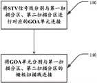
如图2,图2是本发明中一种基于STV控制的分区栅极扫描方法第三实施例示意图;步骤100还包括:步骤130、将STV信号线分别与第一扫描分区10、第二扫描分区20进行对应的GOA单元13连接;步骤140、将GOA单元13分别与第一扫描分区10、第二扫描分区20的栅极扫描线14连接;其中,STV信号线数量为1个。As shown in Fig. 2, Fig. 2 is a schematic diagram of the third embodiment of a partition gate scanning method based on STV control in the present invention; step 100 also includes:
如图6,图6是本发明中显示面板第一实施例示意图;实施例3与实施例2不同的是,实施例3对STV信号线进行了具体的限定。在本实施方式中,采用1根STV信号线STVL,该1根STV信号线STVL需要分别与两个扫描分区的GOA单元13进行连接,具体的说,该1根STV信号线STVL上部与第一扫描分区10上部的GOA单元13连接,该1根STV信号线STVL中部与第二扫描分区20上部的GOA单元13连接。As shown in FIG. 6 , FIG. 6 is a schematic diagram of the first embodiment of the display panel in the present invention; the difference between embodiment 3 and embodiment 2 is that embodiment 3 specifically limits the STV signal line. In this embodiment, one STV signal line STVL is used, and the one STV signal line STVL needs to be connected to the
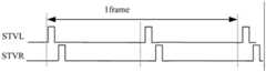
如图7,图7是本发明中显示面板第一实施例的时序图示意图;在扫描时,控制单元11在一帧扫描周期内,分时驱动,STV信号线中STVL信号线分时输出时序,同时从上部→中间,中间→下部驱动扫描。As shown in Fig. 7, Fig. 7 is a schematic diagram of the timing diagram of the first embodiment of the display panel in the present invention; during scanning, the
在扫描时,也可以,控制单元11在一帧扫描周期内,分时驱动,STV信号线中STVL信号线分时输出时序,同时从中间→上部,下部→中间驱动扫描。During scanning, it is also possible that the
实施例4:Example 4:
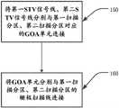
如图3,图3是本发明中一种基于STV控制的分区栅极扫描方法第四实施例示意图;步骤100还包括:步骤150、将第一STV信号线、第二STV信号线分别与第一扫描分区10、第二扫描分区20对应的GOA单元13连接;步骤160、将GOA单元13分别与第一扫描分区10、第二扫描分区20的栅极扫描线14连接;其中,STV信号线包括第一STV信号线及第二STV信号线。As shown in Fig. 3, Fig. 3 is a schematic diagram of the fourth embodiment of a method of partition gate scanning based on STV control in the present invention; step 100 also includes:
如图9,图9是本发明中显示面板第三实施例示意图;实施例4与实施例3不同的是,实施例4采用两根STV信号线,也即第一STV信号线STVL1及第二STV信号线STVL2。As shown in Figure 9, Figure 9 is a schematic diagram of the third embodiment of the display panel in the present invention; the difference between embodiment 4 and embodiment 3 is that embodiment 4 uses two STV signal lines, that is, the first STV signal line STVL1 and the second STV signal line STV signal line STVL2.
在本实施方式中,采用2根STV信号线,也即第一STV信号线STVL1及第二STV信号线STVL2,第一STV信号线STVL1及第二STV信号线STVL2需要分别与两个扫描分区的GOA单元13进行连接。具体的说,第一STV信号线STVL1与第一扫描分区10上部的GOA单元13连接,第二STV信号线STVL2与第二扫描分区20上部的GOA单元13连接。In this embodiment, two STV signal lines are used, that is, the first STV signal line STVL1 and the second STV signal line STVL2. The
如图10,图10是本发明中显示面板第三实施例的时序图示意图;在扫描时,控制单元11在一帧扫描周期内,第一STV信号线中STVL1信号线从显示面板上部→中间(第一扫描分区10的上部开始)驱动扫描,第二STV信号线中STVL2信号线从显示面板中间→下部(第二扫描分区20的上部开始)驱动扫描,As shown in Figure 10, Figure 10 is a schematic diagram of the timing diagram of the third embodiment of the display panel in the present invention; during scanning, the
在扫描时,也可以控制单元11在一帧扫描周期内,第一STV信号线中STVL1信号线从显示面板中间→上部(第一扫描分区10的下部开始)驱动扫描,第二STV信号线中STVL2信号线从显示面板下部→中间(第二扫描分区20的下部开始)驱动扫描。During scanning, the
实施例5:Example 5:
如图8,图8是本发明中显示面板第二实施例示意图;步骤100还包括:步骤120、以公共电极VCOM块15为单位将显示面板分为多个扫描分区。As shown in FIG. 8 , FIG. 8 is a schematic diagram of the second embodiment of the display panel in the present invention; step 100 also includes: step 120 , dividing the display panel into multiple scanning partitions with the common
实施例5与实施例2不同的是,实施例5以以公共电极VCOM块15为单位将显示面板分为多个扫描分区,其扫描分区数量大于两个,例如可以两个公共电极VCOM块15的边界宽度间隔对显示面板进行横向分割,也可以以更多公共电极VCOM块15的边界宽度间隔对显示面板进行横向分割。The difference between embodiment 5 and embodiment 2 is that in embodiment 5, the display panel is divided into multiple scanning partitions with the common
实施例6:Embodiment 6:
如图4,图4是本发明中一种基于STV控制的分区栅极扫描方法第六实施例示意图;步骤100还包括:步骤170、将STV信号线分别与多个扫描分区的GOA单元13对应连接;步骤180、将GOA单元13分别与对应扫描分区的栅极扫描线14连接;其中,STV信号线数量为1个。As shown in Fig. 4, Fig. 4 is a schematic diagram of the sixth embodiment of a partitioned gate scanning method based on STV control in the present invention; step 100 also includes:
实施例6与实施例5不同的是,采用1根STV信号线连接更多扫描分区的GOA单元13,与连接原理与实施例3相同,其扫描原理也与实施例3相同。The difference between embodiment 6 and embodiment 5 is that one STV signal line is used to connect
实施例7:Embodiment 7:
如图5,图5是本发明中一种基于STV控制的分区栅极扫描方法第七实施例示意图;步骤100还包括:步骤190、将多个STV信号线分别与多个扫描分区一一对应设置;步骤191、将STV信号线与对应的GOA单元13连接;步骤192、将GOA单元13分别与对应扫描分区的栅极扫描线14连接;STV信号线数量与扫描分区数量相等。As shown in Fig. 5, Fig. 5 is a schematic diagram of the seventh embodiment of a partitioned gate scanning method based on STV control in the present invention; step 100 also includes:
实施例7与实施例4不同的是,采用多根根STV信号线连接更多扫描分区的GOA单元13,与连接原理与实施例4相同,其扫描原理也与实施例4相同。The difference between embodiment 7 and embodiment 4 is that multiple STV signal lines are used to connect
第二方面,一种显示面板。In the second aspect, a display panel.
实施例1:如图11,图11是本发明中显示面板模块连接示意图;一种显示面板,采用第一方面的分区域栅极驱动扫描方法,包括:STV信号线、GOA单元13、公共电极VCOM块15、栅极扫描线14及控制单元11。Embodiment 1: As shown in Figure 11, Figure 11 is a schematic diagram of the connection of the display panel module in the present invention; a display panel adopts the sub-area gate driving scanning method of the first aspect, including: STV signal line,
栅极扫描线14依次平行排列在公共电极VCOM块15上;GOA单元13分别设置在栅极扫描线14两侧,并与栅极扫描线14连接;STV信号线分别与两侧对应的GOA单元13连接;控制单元11分别与STV信号线、公共电极VCOM块15连接;控制单元11用于将驱动时序传输到STV信号线;STV信号线用于根据驱动时序驱动GOA单元13,以使得所有的扫描分区同时启动扫描;GOA单元13用于根据STV信号线的控制信号对扫描分区对应的栅极线进行扫描。The
实施例2:如图6,扫描分区包括:第一扫描分区10及第二扫描分区20;STV信号线数量为1个;将STV信号线分别与第一扫描分区10、第二扫描分区20进行对应的GOA单元13连接,将GOA单元13分别与第一扫描分区10、第二扫描分区20的栅极扫描线14连接。Embodiment 2: As shown in Figure 6, the scan partitions include: the first scan partition 10 and the
第二方面实施例2与第一方面实施例3原理相同。Embodiment 2 of the second aspect is the same in principle as Embodiment 3 of the first aspect.
实施例3:如图9,扫描分区包括:第一扫描分区10及第二扫描分区20;Embodiment 3: As shown in Figure 9, the scanning partitions include: a first scanning partition 10 and a
STV信号线数量为2个;The number of STV signal lines is 2;
将第一STV信号线、第二第一STV信号线分别与第一扫描分区10、第二扫描分区20对应的GOA单元13连接;Connect the first STV signal line and the second first STV signal line to the
将GOA单元13分别与第一扫描分区10、第二扫描分区20的栅极扫描线14连接。The
第二方面实施例3与第一方面实施例4原理相同。Embodiment 3 of the second aspect is the same in principle as Embodiment 4 of the first aspect.
实施本发明的一种基于STV控制的分区栅极扫描方法及显示面板,通过对显示面板进行分区并通过单个或多个STV信号线输出驱动控制信号,控制GOA单元13对扫描分区的栅极扫描线14进行同时扫描,有效减轻了TDDI类显示面板的显示横纹。Implementing a partition gate scanning method based on STV control and a display panel of the present invention, by partitioning the display panel and outputting a driving control signal through a single or multiple STV signal lines, controlling the gate scanning of the scanning partition by the
以上仅为本发明的较佳实施例,并不用以限制本发明,凡在本发明的精神和原则之内,所作的任何修改、等同替换、改进等,均应包含在本发明的保护范围之内。The above are only preferred embodiments of the present invention, and are not intended to limit the present invention. Any modifications, equivalent replacements, improvements, etc. made within the spirit and principles of the present invention shall be included in the protection scope of the present invention Inside.
Claims (10)
Priority Applications (1)
| Application Number | Priority Date | Filing Date | Title |
|---|---|---|---|
| CN202210954049.5ACN115311976A (en) | 2022-08-09 | 2022-08-09 | STV control-based partition grid scanning method and display panel |
Applications Claiming Priority (1)
| Application Number | Priority Date | Filing Date | Title |
|---|---|---|---|
| CN202210954049.5ACN115311976A (en) | 2022-08-09 | 2022-08-09 | STV control-based partition grid scanning method and display panel |
Publications (1)
| Publication Number | Publication Date |
|---|---|
| CN115311976Atrue CN115311976A (en) | 2022-11-08 |
Family
ID=83861427
Family Applications (1)
| Application Number | Title | Priority Date | Filing Date |
|---|---|---|---|
| CN202210954049.5APendingCN115311976A (en) | 2022-08-09 | 2022-08-09 | STV control-based partition grid scanning method and display panel |
Country Status (1)
| Country | Link |
|---|---|
| CN (1) | CN115311976A (en) |
Citations (11)
| Publication number | Priority date | Publication date | Assignee | Title |
|---|---|---|---|---|
| US20030122771A1 (en)* | 2001-10-23 | 2003-07-03 | Nec Corporation | Liquid crystal display device, backlight used for same display device, method for driving same backlight and method for manufacturing same backlight |
| US6614412B1 (en)* | 1999-09-01 | 2003-09-02 | Nec Corporation | Apparatus, manufacturing method and driving method of plasma display panel |
| CN1957391A (en)* | 2004-05-24 | 2007-05-02 | 索尼株式会社 | Display device and display device driving method |
| CN101266371A (en)* | 2007-03-13 | 2008-09-17 | 上海天马微电子有限公司 | Field sequential liquid crystal display device and driving method thereof |
| CN105185335A (en)* | 2015-09-23 | 2015-12-23 | 昆山龙腾光电有限公司 | Gate drive circuit and liquid crystal display device |
| CN106328081A (en)* | 2016-10-09 | 2017-01-11 | 武汉华星光电技术有限公司 | Flexible display and drive method thereof |
| CN108305586A (en)* | 2017-01-11 | 2018-07-20 | 三星显示有限公司 | display device |
| CN110288942A (en)* | 2019-06-28 | 2019-09-27 | 上海天马有机发光显示技术有限公司 | A kind of display panel and display device |
| CN110310594A (en)* | 2019-07-22 | 2019-10-08 | 京东方科技集团股份有限公司 | Display panel and display device |
| CN111710286A (en)* | 2020-06-30 | 2020-09-25 | 上海中航光电子有限公司 | Display panel, drive control method thereof, and display device |
| CN113936607A (en)* | 2020-07-14 | 2022-01-14 | 三星显示有限公司 | Display device |
- 2022
- 2022-08-09CNCN202210954049.5Apatent/CN115311976A/enactivePending
Patent Citations (11)
| Publication number | Priority date | Publication date | Assignee | Title |
|---|---|---|---|---|
| US6614412B1 (en)* | 1999-09-01 | 2003-09-02 | Nec Corporation | Apparatus, manufacturing method and driving method of plasma display panel |
| US20030122771A1 (en)* | 2001-10-23 | 2003-07-03 | Nec Corporation | Liquid crystal display device, backlight used for same display device, method for driving same backlight and method for manufacturing same backlight |
| CN1957391A (en)* | 2004-05-24 | 2007-05-02 | 索尼株式会社 | Display device and display device driving method |
| CN101266371A (en)* | 2007-03-13 | 2008-09-17 | 上海天马微电子有限公司 | Field sequential liquid crystal display device and driving method thereof |
| CN105185335A (en)* | 2015-09-23 | 2015-12-23 | 昆山龙腾光电有限公司 | Gate drive circuit and liquid crystal display device |
| CN106328081A (en)* | 2016-10-09 | 2017-01-11 | 武汉华星光电技术有限公司 | Flexible display and drive method thereof |
| CN108305586A (en)* | 2017-01-11 | 2018-07-20 | 三星显示有限公司 | display device |
| CN110288942A (en)* | 2019-06-28 | 2019-09-27 | 上海天马有机发光显示技术有限公司 | A kind of display panel and display device |
| CN110310594A (en)* | 2019-07-22 | 2019-10-08 | 京东方科技集团股份有限公司 | Display panel and display device |
| CN111710286A (en)* | 2020-06-30 | 2020-09-25 | 上海中航光电子有限公司 | Display panel, drive control method thereof, and display device |
| CN113936607A (en)* | 2020-07-14 | 2022-01-14 | 三星显示有限公司 | Display device |
Similar Documents
| Publication | Publication Date | Title |
|---|---|---|
| US6342876B1 (en) | Method and apparatus for driving liquid crystal panel in cycle inversion | |
| WO2014000362A1 (en) | Method for driving touch display screen | |
| US20080048963A1 (en) | Display method for improving image quality and device used the same | |
| CN102411891B (en) | Display device and drive method thereof | |
| US7286107B2 (en) | Liquid crystal display | |
| JPH1073843A (en) | Active matrix type liquid crystal display device | |
| WO2014153858A1 (en) | Touch screen and drive method thereof, and display device | |
| US20040041769A1 (en) | Display apparatus | |
| JPH08211411A (en) | Liquid crystal panel and liquid crystal display device | |
| CN102282860A (en) | Method for driving stereoscopic display device, and stereoscopic display device | |
| US20090122005A1 (en) | Liquid crystal display device and driving method thereof | |
| CN1664659B (en) | Liquid crystal display device and method for driving the same | |
| CN102378031A (en) | Electro-optical device and electronic apparatus | |
| JP2005196135A (en) | Driving method and driving circuit for liquid crystal display device | |
| CN106652952A (en) | Driving method, display panel and dot inversion driving method thereof | |
| CN115311976A (en) | STV control-based partition grid scanning method and display panel | |
| JP3903736B2 (en) | Electro-optical panel, driving circuit thereof, driving method, and electronic apparatus | |
| KR102050435B1 (en) | Touch display device | |
| JP2002214645A (en) | Active matrix display device | |
| JPH0477515B2 (en) | ||
| WO2015089876A1 (en) | Display apparatus and display driving method | |
| JP2005164705A (en) | Signal circuit, display device using the same, and data line driving method | |
| JP2005242311A (en) | Driving method of liquid crystal display device | |
| CN117809584A (en) | Display panel, driving method thereof and display device | |
| CN114895807B (en) | A touch display scanning method and touch display screen |
Legal Events
| Date | Code | Title | Description |
|---|---|---|---|
| PB01 | Publication | ||
| PB01 | Publication | ||
| SE01 | Entry into force of request for substantive examination | ||
| SE01 | Entry into force of request for substantive examination | ||
| RJ01 | Rejection of invention patent application after publication | Application publication date:20221108 | |
| RJ01 | Rejection of invention patent application after publication |