CN115308672A - Electric energy metering device fault analysis method based on VV wiring traction transformer - Google Patents
Electric energy metering device fault analysis method based on VV wiring traction transformerDownload PDFInfo
- Publication number
- CN115308672A CN115308672ACN202210725511.4ACN202210725511ACN115308672ACN 115308672 ACN115308672 ACN 115308672ACN 202210725511 ACN202210725511 ACN 202210725511ACN 115308672 ACN115308672 ACN 115308672A
- Authority
- CN
- China
- Prior art keywords
- voltage
- target
- current
- phase
- electric energy
- Prior art date
- Legal status (The legal status is an assumption and is not a legal conclusion. Google has not performed a legal analysis and makes no representation as to the accuracy of the status listed.)
- Pending
Links
Images


Classifications
- G—PHYSICS
- G01—MEASURING; TESTING
- G01R—MEASURING ELECTRIC VARIABLES; MEASURING MAGNETIC VARIABLES
- G01R35/00—Testing or calibrating of apparatus covered by the other groups of this subclass
- G01R35/04—Testing or calibrating of apparatus covered by the other groups of this subclass of instruments for measuring time integral of power or current
- G—PHYSICS
- G01—MEASURING; TESTING
- G01R—MEASURING ELECTRIC VARIABLES; MEASURING MAGNETIC VARIABLES
- G01R15/00—Details of measuring arrangements of the types provided for in groups G01R17/00 - G01R29/00, G01R33/00 - G01R33/26 or G01R35/00
- G01R15/14—Adaptations providing voltage or current isolation, e.g. for high-voltage or high-current networks
- G01R15/18—Adaptations providing voltage or current isolation, e.g. for high-voltage or high-current networks using inductive devices, e.g. transformers
- G—PHYSICS
- G01—MEASURING; TESTING
- G01R—MEASURING ELECTRIC VARIABLES; MEASURING MAGNETIC VARIABLES
- G01R25/00—Arrangements for measuring phase angle between a voltage and a current or between voltages or currents
- G—PHYSICS
- G01—MEASURING; TESTING
- G01R—MEASURING ELECTRIC VARIABLES; MEASURING MAGNETIC VARIABLES
- G01R29/00—Arrangements for measuring or indicating electric quantities not covered by groups G01R19/00 - G01R27/00
- G01R29/18—Indicating phase sequence; Indicating synchronism
Landscapes
- Physics & Mathematics (AREA)
- General Physics & Mathematics (AREA)
- Engineering & Computer Science (AREA)
- Power Engineering (AREA)
- Supply And Distribution Of Alternating Current (AREA)
Abstract
Description
Translated fromChinese技术领域technical field
本申请涉及故障检测技术领域,尤其是涉及到一种基于VV接线牵引变压器的电能计量装置故障分析方法及装置、存储介质、计算机设备。The present application relates to the technical field of fault detection, in particular to a fault analysis method and device, a storage medium, and a computer device for an electric energy metering device based on a VV connection traction transformer.
背景技术Background technique
牵引变压器是连接电力系统和牵引供电系统的关键,牵引变压器的主要作用是变压以及向牵引供电负荷传递功率。VV接线牵引变压器有很多优势,例如结构简单、经济效益较高等,因而使用范围较为广泛。The traction transformer is the key to connect the power system and the traction power supply system. The main function of the traction transformer is to transform the voltage and transmit power to the traction power supply load. VV wiring traction transformers have many advantages, such as simple structure and high economic benefits, so they are widely used.
现有技术中对VV接线牵引变压器的电能计量装置进行故障分析时,主要通过计量人员现场使用相位伏安表等测试仪器,在电能表端钮盒处测试电压、电流、相位等数据,进而通过这些数据进行故障分析。这种方式需要计量人员在带电的计量回路接线操作,对计量人员的人身安全造成极大威胁,且清理电流互感器、电压互感器的二次回路接线时,需要使VV接线牵引变压器停电,导致由牵引变压器供电的机车等不能正常运转。此外,由于VV接线牵引变压器本身的结构特点,导致计量人员故障分析准确率较低。In the prior art, when the fault analysis of the electric energy metering device of the VV wiring traction transformer is carried out, the measurement personnel mainly use the phase voltammeter and other testing instruments on site to test the data of voltage, current, phase and so on at the terminal button box of the electric energy meter, and then pass These data are used for failure analysis. This method requires metering personnel to operate on live metering circuit wiring, which poses a great threat to the personal safety of metering personnel. When cleaning the secondary circuit wiring of current transformers and voltage transformers, it is necessary to cut off the power of the VV wiring traction transformer, resulting in Locomotives, etc. powered by traction transformers cannot operate normally. In addition, due to the structural characteristics of the VV wiring traction transformer itself, the accuracy of fault analysis by metering personnel is low.
发明内容Contents of the invention
有鉴于此,本申请提供了一种基于VV接线牵引变压器的电能计量装置故障分析方法及装置、存储介质、计算机设备,可以在VV接线牵引变压器不停电的情况下,根据VV接线牵引变压器的负荷特性自动分析VV接线牵引变压器的电能计量装置是否存在故障,准确方便。In view of this, the present application provides a fault analysis method and device, a storage medium, and a computer equipment for an electric energy metering device based on a VV connection traction transformer, which can be used according to the load of the VV connection traction transformer when the VV connection traction transformer is not powered off. Features Automatically analyze whether there is a fault in the electric energy metering device of the VV wiring traction transformer, which is accurate and convenient.
根据本申请的一个方面,提供了一种基于VV接线牵引变压器的电能计量装置故障分析方法,包括:According to one aspect of the present application, a fault analysis method for a power metering device based on a VV wiring traction transformer is provided, including:
确定所述VV接线牵引变压器的原边绕组电压接入相别,其中,所述VV接线牵引变压器由第一单相变压器以及第二单相变压器组成;It is determined that the primary winding voltage of the VV connection traction transformer is connected to the phase, wherein the VV connection traction transformer is composed of a first single-phase transformer and a second single-phase transformer;
将所述第一单相变压器与所述第二单相变压器同时接入单相牵引负荷,依据预设电能表确定对应的目标参数,其中,所述预设电能表包括多个目标元件,所述目标参数包括相别顺序以及每个所述目标元件对应的电压值、电流值、功率因数值、无功功率值;Connect the first single-phase transformer and the second single-phase transformer to the single-phase traction load at the same time, and determine the corresponding target parameters according to the preset electric energy meter, wherein the preset electric energy meter includes a plurality of target components, so The target parameters include a different order and the corresponding voltage value, current value, power factor value, and reactive power value of each target element;
基于所述预设电能表对应的所述目标参数,确定目标相量图,其中,所述目标相量图包括各个所述目标元件对应的电压向量、电流向量以及每个所述电压向量、电流向量对应的相别;Determine the target phasor diagram based on the target parameters corresponding to the preset electric energy meter, wherein the target phasor diagram includes voltage vectors, current vectors and each of the voltage vectors and currents corresponding to each of the target elements The difference corresponding to the vector;
基于所述目标相量图中每个所述电压向量以及所述电流向量对应的所述相别,确定所述预设电能表对应的电压相序以及电流相序;Based on the phase difference corresponding to each of the voltage vectors and the current vectors in the target phasor diagram, determine a voltage phase sequence and a current phase sequence corresponding to the preset electric energy meter;
基于所述原边绕组电压接入相别以及所述预设电能表对应的所述电压相序以及所述电流相序,确定所述电能计量装置是否存在故障。Based on the voltage access phase of the primary winding and the voltage phase sequence and the current phase sequence corresponding to the preset electric energy meter, it is determined whether there is a fault in the electric energy metering device.
根据本申请的另一方面,提供了一种基于VV接线牵引变压器的电能计量装置故障分析装置,包括:According to another aspect of the present application, a fault analysis device for a power metering device based on a VV wiring traction transformer is provided, including:
接入相别确定模块,用于确定所述VV接线牵引变压器的原边绕组电压接入相别,其中,所述VV接线牵引变压器由第一单相变压器以及第二单相变压器组成;The access phase determination module is used to determine the access phase of the primary winding voltage of the VV connection traction transformer, wherein the VV connection traction transformer is composed of a first single-phase transformer and a second single-phase transformer;
目标参数确定模块,用于将所述第一单相变压器与所述第二单相变压器同时接入单相牵引负荷,依据预设电能表确定对应的目标参数,其中,所述预设电能表包括多个目标元件,所述目标参数包括相别顺序以及每个所述目标元件对应的电压值、电流值、功率因数值、无功功率值;A target parameter determination module, configured to simultaneously connect the first single-phase transformer and the second single-phase transformer to a single-phase traction load, and determine corresponding target parameters according to a preset electric energy meter, wherein the preset electric energy meter Including a plurality of target components, the target parameters include a different sequence and each target component corresponds to a voltage value, a current value, a power factor value, and a reactive power value;
目标相量图确定模块,用于基于所述预设电能表对应的所述目标参数,确定目标相量图,其中,所述目标相量图包括各个所述目标元件对应的电压向量、电流向量以及每个所述电压向量、电流向量对应的相别;A target phasor diagram determining module, configured to determine a target phasor diagram based on the target parameters corresponding to the preset electric energy meter, wherein the target phasor diagram includes voltage vectors and current vectors corresponding to each of the target elements And the phase difference corresponding to each of the voltage vectors and current vectors;
相序确定模块,用于基于所述目标相量图中每个所述电压向量以及所述电流向量对应的所述相别,确定所述预设电能表对应的电压相序以及电流相序;A phase sequence determination module, configured to determine the voltage phase sequence and current phase sequence corresponding to the preset electric energy meter based on the phase difference corresponding to each of the voltage vectors and the current vector in the target phasor diagram;
故障确定模块,用于基于所述原边绕组电压接入相别以及所述预设电能表对应的所述电压相序以及所述电流相序,确定所述电能计量装置是否存在故障。A fault determination module, configured to determine whether there is a fault in the electric energy metering device based on the voltage access phase of the primary winding and the voltage phase sequence and the current phase sequence corresponding to the preset electric energy meter.
依据本申请又一个方面,提供了一种存储介质,其上存储有计算机程序,所述程序被处理器执行时实现上述基于VV接线牵引变压器的电能计量装置故障分析方法。According to still another aspect of the present application, a storage medium is provided, on which a computer program is stored, and when the program is executed by a processor, the above-mentioned fault analysis method for an electric energy metering device based on a VV wiring traction transformer is implemented.
依据本申请再一个方面,提供了一种计算机设备,包括存储介质、处理器及存储在存储介质上并可在处理器上运行的计算机程序,所述处理器执行所述程序时实现上述基于VV接线牵引变压器的电能计量装置故障分析方法。According to yet another aspect of the present application, a computer device is provided, including a storage medium, a processor, and a computer program stored on the storage medium and operable on the processor. When the processor executes the program, the above-mentioned VV-based Fault analysis method for electric energy metering device of wiring traction transformer.
借由上述技术方案,本申请提供的一种基于VV接线牵引变压器的电能计量装置故障分析方法及装置、存储介质、计算机设备,首先,可以对VV接线牵引变压器的原边绕组电压接入相别进行确认,在这里,将VV接线牵引变压器的两台单相变压器称作第一单相变压器和第二单相变压器。之后,可以将第一单相变压器和第二单相变压器同时接入单相牵引负荷。接入单相牵引负荷时,可以通过预设电能表读取对应的目标参数。确定同时接入第一单相变压器以及第二单相变压器对应的目标参数之后,可以以目标参数为基础,通过目标参数中的电压值、电流值、功率因数值等,确定对应的目标相量图。得到目标相量图之后,可以以目标相量图为基础,通过目标相量图中的各个电压向量对应的相别以及电流向量对应的相别,确定预设电能表对应的电压相序和电流相序。确定预设电能表对应的电压相序和电流相序之后,可以进一步将电压相序和电流相序与VV接线牵引变压器对应的原边绕组电压接入相别进行对比,最终确定VV接线牵引变压器的电能计量装置是否存在故障。By virtue of the above technical solutions, the present application provides a fault analysis method and device, storage medium, and computer equipment for an electric energy metering device based on a VV connection traction transformer. For confirmation, here, the two single-phase transformers of the VV-connection traction transformer are referred to as a first single-phase transformer and a second single-phase transformer. After that, the first single-phase transformer and the second single-phase transformer can be connected to the single-phase traction load at the same time. When the single-phase traction load is connected, the corresponding target parameters can be read through the preset electric energy meter. After determining the target parameters corresponding to the simultaneous access to the first single-phase transformer and the second single-phase transformer, the corresponding target phasor can be determined based on the target parameters through the voltage value, current value, power factor value, etc. in the target parameters picture. After the target phasor diagram is obtained, based on the target phasor diagram, the voltage phase sequence and current corresponding to the preset electric energy meter can be determined through the phase difference corresponding to each voltage vector and current vector in the target phasor diagram phase sequence. After determining the voltage phase sequence and current phase sequence corresponding to the preset electric energy meter, the voltage phase sequence and current phase sequence can be further compared with the primary winding voltage access phase corresponding to the VV connection traction transformer, and finally determine the VV connection traction transformer Whether there is a fault in the electric energy metering device.
上述说明仅是本申请技术方案的概述,为了能够更清楚了解本申请的技术手段,而可依照说明书的内容予以实施,并且为了让本申请的上述和其它目的、特征和优点能够更明显易懂,以下特举本申请的具体实施方式。The above description is only an overview of the technical solution of the present application. In order to better understand the technical means of the present application, it can be implemented according to the contents of the description, and in order to make the above and other purposes, features and advantages of the present application more obvious and understandable , the following specifically cites the specific implementation manner of the present application.
附图说明Description of drawings
此处所说明的附图用来提供对本申请的进一步理解,构成本申请的一部分,本申请的示意性实施例及其说明用于解释本申请,并不构成对本申请的不当限定。在附图中:The drawings described here are used to provide a further understanding of the application and constitute a part of the application. The schematic embodiments and descriptions of the application are used to explain the application and do not constitute an improper limitation to the application. In the attached picture:
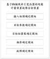
图1示出了本申请实施例提供的一种基于VV接线牵引变压器的电能计量装置故障分析方法的流程示意图;Fig. 1 shows a schematic flowchart of a fault analysis method for an electric energy metering device based on a VV wiring traction transformer provided by an embodiment of the present application;
图2示出了本申请实施例提供的另一种基于VV接线牵引变压器的电能计量装置故障分析方法的流程示意图;FIG. 2 shows a schematic flowchart of another fault analysis method for an electric energy metering device based on a VV wiring traction transformer provided by an embodiment of the present application;
图3示出了本申请实施例提供的一种电压相量图;FIG. 3 shows a voltage phasor diagram provided by an embodiment of the present application;
图4示出了本申请实施例提供的一种电压-电流相量图;FIG. 4 shows a voltage-current phasor diagram provided by an embodiment of the present application;
图5示出了本申请实施例提供的一种目标相量图;FIG. 5 shows a target phasor diagram provided by an embodiment of the present application;
图6示出了本申请实施例提供的一种基于VV接线牵引变压器的电能计量装置故障分析装置的结构示意图。Fig. 6 shows a schematic structural diagram of a fault analysis device for an electric energy metering device based on a VV connection traction transformer provided by an embodiment of the present application.
具体实施方式Detailed ways
下文中将参考附图并结合实施例来详细说明本申请。需要说明的是,在不冲突的情况下,本申请中的实施例及实施例中的特征可以相互组合。Hereinafter, the present application will be described in detail with reference to the drawings and embodiments. It should be noted that, in the case of no conflict, the embodiments in the present application and the features in the embodiments can be combined with each other.
在本实施例中提供了一种基于VV接线牵引变压器的电能计量装置故障分析方法,如图1所示,该方法包括:In this embodiment, a fault analysis method for an electric energy metering device based on a VV wiring traction transformer is provided, as shown in FIG. 1 , the method includes:
步骤101,确定所述VV接线牵引变压器的原边绕组电压接入相别,其中,所述VV接线牵引变压器由第一单相变压器以及第二单相变压器组成;Step 101, determining that the primary winding voltage of the VV connection traction transformer is connected to the phase, wherein the VV connection traction transformer is composed of a first single-phase transformer and a second single-phase transformer;
本申请实施例提供的基于VV接线牵引变压器的电能计量装置的故障分析方法,可以准确确定VV接线牵引变压器的电能计量装置是否存在故障与异常。在本申请实施例中,电能计量装置包括电流互感器、电压互感器以及预设电能表,也包括计量二次回路等其他电能计量装置。VV接线牵引变压器回路中连接有电流互感器、电压互感器,以及与电流互感器和电压互感器连接的预设电能表,通过预设电能表可以读出电流值、电压值等数据。预设电能表是安装在牵引变电站计量屏柜上,通过二次回路与电压互感器、电流互感器连接在一起。可以将VV接线牵引变压器看作两台单相变压器,其中,原边AB绕组可以和副边绕组构成α臂;原边BC绕组可以和副边绕组构成β臂。为了抑制负序分量影响,不同的牵引变压器一次接入相别不同,存在一次接入ABC、CAB、BCA、ACB、CBA、BAC六种相别的情况,且运行中经常出现单相负荷等运行方式,因而呈现出特殊的相量特性、电流特性,通过现有技术中电能计量装置的故障分析方法对VV接线牵引变压器的电能计量装置进行故障分析,准确度较低。本申请的基于VV接线牵引变压器的电能计量装置故障分析方法,首先,可以对VV接线牵引变压器的原边绕组电压接入相别进行确认。VV接线牵引变压器存在一次接入ABC、CAB、BCA、ACB、CBA、BAC六种相别的情况。在这里,将VV接线牵引变压器的两台单相变压器称作第一单相变压器和第二单相变压器。The fault analysis method based on the electric energy metering device of the VV connection traction transformer provided by the embodiment of the present application can accurately determine whether the electric energy metering device of the VV connection traction transformer is faulty or abnormal. In the embodiment of the present application, the electric energy metering device includes a current transformer, a voltage transformer, and a preset electric energy meter, and also includes other electric energy metering devices such as a metering secondary circuit. The VV wiring traction transformer circuit is connected with a current transformer, a voltage transformer, and a preset watt-hour meter connected to the current transformer and the voltage transformer. The current value, voltage value and other data can be read through the preset watt-hour meter. The preset electric energy meter is installed on the metering cabinet of the traction substation, and is connected with the voltage transformer and current transformer through the secondary circuit. The VV connection traction transformer can be regarded as two single-phase transformers, in which the primary AB winding can form an α arm with the secondary winding; the primary BC winding can form a β arm with the secondary winding. In order to suppress the influence of negative sequence components, different traction transformers are connected to different phases at one time. There are six phases of ABC, CAB, BCA, ACB, CBA, and BAC connected at one time, and single-phase loads often occur during operation. Therefore, it presents special phasor characteristics and current characteristics. The accuracy of the fault analysis of the electric energy metering device of the VV wiring traction transformer is low through the fault analysis method of the electric energy metering device in the prior art. According to the fault analysis method of the electric energy metering device based on the VV connection traction transformer of the present application, firstly, the voltage access phase of the primary winding of the VV connection traction transformer can be confirmed. There are six phases of ABC, CAB, BCA, ACB, CBA, and BAC connected to the VV wiring traction transformer at one time. Here, the two single-phase transformers of the VV connection traction transformer are referred to as a first single-phase transformer and a second single-phase transformer.
步骤102,将所述第一单相变压器与所述第二单相变压器同时接入单相牵引负荷,依据预设电能表确定对应的目标参数,其中,所述预设电能表包括多个目标元件,所述目标参数包括相别顺序以及每个所述目标元件对应的电压值、电流值、功率因数值、无功功率值;
在该实施例中,可以将第一单相变压器和第二单相变压器同时接入单相牵引负荷。接入单相牵引负荷时,可以通过预设电能表读取对应的目标参数。在这里,预设电能表中可以包括多个目标元件,对于三相四线智能电能表,目标元件可以是三个,目标参数可以是每个目标元件对应的电流值、电压值、功率因数值、无功功率值等,此外还可以包括相别顺序。例如,预设电能表可以是三相四线智能电能表,该三相四线智能电能表中可以包括三个目标元件。在接入单相牵引负荷时,通过预设电能表读取到的电流可以是I1=0.21A,I2=0.36A,I3=0.21A,电压是U1=60.2V,U2=60.5V,U3=59.7V,功率因数是


步骤103,基于所述预设电能表对应的所述目标参数,确定目标相量图,其中,所述目标相量图包括各个所述目标元件对应的电压向量、电流向量以及每个所述电压向量、电流向量对应的相别;Step 103: Determine a target phasor diagram based on the target parameters corresponding to the preset electric energy meter, wherein the target phasor diagram includes a voltage vector, a current vector and each of the voltage vectors corresponding to each of the target elements The phase difference corresponding to vector and current vector;
在该实施例中,确定同时接入第一单相变压器以及第二单相变压器对应的目标参数之后,可以以目标参数为基础,通过目标参数中的电压值、电流值、功率因数值等,确定对应的目标相量图。在这里,目标相量图是包括预设电能表中每个目标元件对应的电压向量与电流向量的相量图,且在目标相量图中可以看出每个电压向量和每个电流向量对应的相别。In this embodiment, after determining the target parameters corresponding to the simultaneous access to the first single-phase transformer and the second single-phase transformer, based on the target parameters, the voltage value, current value, power factor value, etc. in the target parameters can be used to determine Determine the corresponding target phasor diagram. Here, the target phasor diagram is a phasor diagram including the voltage vector and current vector corresponding to each target element in the preset electric energy meter, and it can be seen in the target phasor diagram that each voltage vector corresponds to each current vector the difference.
步骤104,基于所述目标相量图中每个所述电压向量以及所述电流向量对应的所述相别,确定所述预设电能表对应的电压相序以及电流相序;
在该实施例中,得到目标相量图之后,可以以目标相量图为基础,通过目标相量图中的各个电流向量、电压向量对应的相别,确定预设电能表对应的电压相序和电流相序。例如,通过目标相量图看出第一目标元件对应的电压向量、电流向量的相别分别为


步骤105,基于所述原边绕组电压接入相别以及所述预设电能表对应的所述电压相序以及所述电流相序,确定所述电能计量装置是否存在故障。
在该实施例中,确定预设电能表对应的电压相序和电流相序之后,可以进一步将电压相序和电流相序与VV接线牵引变压器对应的原边绕组电压接入相别进行对比,最终确定VV接线牵引变压器的电能计量装置是否存在故障。例如,VV接线牵引变压器的原边绕组电压接入相别为A、C、B,如果预设电能表对应的电压相序和电流相序同样也为A、C、B,那么说明该电能计量装置不存在故障,否则,说明该电能计量装置存在故障。在这里,如果预设电能表对应的电压相序、电流相序和VV接线牵引变压器的原边绕组接入相别不一致,那么说明要么VV接线牵引变压器回路中连接的电压互感器、电流互感器存在接线错误等故障,导致预设电能表获取的电压值、电流值、功率因数值等存在错误;要么与电压互感器、电流互感器连接的预设电能表本身存在故障等。所以,当确定电能计量装置存在故障后,后续可以进一步判断是电能计量装置中的电压互感器、电流互感器存在故障,还是预设电能表存在故障,又或者是计量二次回路等其他电能计量装置存在故障,在此不作介绍。In this embodiment, after determining the voltage phase sequence and current phase sequence corresponding to the preset electric energy meter, the voltage phase sequence and current phase sequence can be further compared with the primary winding voltage access phase corresponding to the VV connection traction transformer, Finally determine whether the electric energy metering device of the VV wiring traction transformer is faulty. For example, the voltage access phases of the primary winding of the traction transformer with VV connection are A, C, and B. If the voltage phase sequence and current phase sequence corresponding to the preset electric energy meter are also A, C, and B, then the electric energy metering If there is no fault in the device, otherwise, it indicates that the electric energy metering device is faulty. Here, if the voltage phase sequence and current phase sequence corresponding to the preset watt-hour meter are inconsistent with the primary winding access phase of the VV connection traction transformer, it means that either the voltage transformer or current transformer connected in the VV connection traction transformer circuit There are faults such as wiring errors, which lead to errors in the voltage value, current value, and power factor value obtained by the preset electric energy meter; or there is a fault in the preset electric energy meter itself connected to the voltage transformer and current transformer. Therefore, when it is determined that there is a fault in the electric energy metering device, it can be further judged whether the voltage transformer and current transformer in the electric energy metering device are faulty, or the preset electric energy meter is faulty, or other electric energy metering such as the secondary circuit of the metering The device is faulty and will not be described here.
通过应用本实施例的技术方案,首先,可以对VV接线牵引变压器的原边绕组电压接入相别进行确认,在这里,将VV接线牵引变压器的两台单相变压器称作第一单相变压器和第二单相变压器。之后,可以将第一单相变压器和第二单相变压器同时接入单相牵引负荷。接入单相牵引负荷时,可以通过预设电能表读取对应的目标参数。确定同时接入第一单相变压器以及第二单相变压器对应的目标参数之后,可以以目标参数为基础,通过目标参数中的电压值、电流值、功率因数值等,确定对应的目标相量图。得到目标相量图之后,可以以目标相量图为基础,通过目标相量图中的各个电压向量对应的相别以及电流向量对应的相别,确定预设电能表对应的电压相序和电流相序。确定预设电能表对应的电压相序和电流相序之后,可以进一步将电压相序和电流相序与VV接线牵引变压器对应的原边绕组电压接入相别进行对比,最终确定VV接线牵引变压器的电能计量装置是否存在故障。By applying the technical solution of this embodiment, firstly, it is possible to confirm the voltage access phases of the primary windings of the VV-connected traction transformer. Here, the two single-phase transformers of the VV-connected traction transformer are referred to as the first single-phase transformer. and a second single-phase transformer. After that, the first single-phase transformer and the second single-phase transformer can be connected to the single-phase traction load at the same time. When the single-phase traction load is connected, the corresponding target parameters can be read through the preset electric energy meter. After determining the target parameters corresponding to the simultaneous access to the first single-phase transformer and the second single-phase transformer, the corresponding target phasor can be determined based on the target parameters through the voltage value, current value, power factor value, etc. in the target parameters picture. After the target phasor diagram is obtained, based on the target phasor diagram, the voltage phase sequence and current corresponding to the preset electric energy meter can be determined through the phase difference corresponding to each voltage vector and current vector in the target phasor diagram phase sequence. After determining the voltage phase sequence and current phase sequence corresponding to the preset electric energy meter, the voltage phase sequence and current phase sequence can be further compared with the primary winding voltage access phase corresponding to the VV connection traction transformer, and finally determine the VV connection traction transformer Whether there is a fault in the electric energy metering device.
进一步的,作为上述实施例具体实施方式的细化和扩展,为了完整说明本实施例的具体实施过程,提供了另一种基于VV接线牵引变压器的电能计量装置故障分析方法,如图2所示,该方法包括:Further, as a refinement and expansion of the specific implementation of the above-mentioned embodiment, in order to fully describe the specific implementation process of this embodiment, another fault analysis method for an electric energy metering device based on a VV connection traction transformer is provided, as shown in Figure 2 , the method includes:
步骤201,确定所述VV接线牵引变压器的原边绕组电压接入相别,其中,所述VV接线牵引变压器由第一单相变压器以及第二单相变压器组成;
在该实施例中,首先,可以对VV接线牵引变压器的原边绕组电压接入相别进行确认。VV接线牵引变压器存在一次接入ABC、CAB、BCA、ACB、CBA、BAC六种相别的情况。在这里,将VV接线牵引变压器的两台单相变压器称作第一单相变压器和第二单相变压器。In this embodiment, firstly, it may be confirmed that the primary winding voltage of the VV connection traction transformer is connected to the phase. There are six phases of ABC, CAB, BCA, ACB, CBA, and BAC connected to the VV wiring traction transformer at one time. Here, the two single-phase transformers of the VV connection traction transformer are referred to as a first single-phase transformer and a second single-phase transformer.
步骤202,将所述第一单相变压器与所述第二单相变压器同时接入单相牵引负荷,依据预设电能表确定对应的目标参数,其中,所述预设电能表包括多个目标元件,所述目标参数包括相别顺序以及每个所述目标元件对应的电压值、电流值、功率因数值、无功功率值;
在该实施例中,可以将第一单相变压器和第二单相变压器同时接入单相牵引负荷。接入单相牵引负荷时,可以通过预设电能表读取对应的目标参数。在这里,目标参数可以是每个目标元件对应的电流值、电压值、功率因数值、无功功率值等,此外还包括相别顺序。In this embodiment, the first single-phase transformer and the second single-phase transformer can be connected to the single-phase traction load at the same time. When the single-phase traction load is connected, the corresponding target parameters can be read through the preset electric energy meter. Here, the target parameter may be the current value, voltage value, power factor value, reactive power value, etc. corresponding to each target element, and also includes a different order.
步骤203,基于所述预设电能表对应的所述相别顺序以及每个所述目标元件对应的所述电压值,确定电压相量图,其中,所述电压相量图中包括各个所述目标元件对应的电压向量;Step 203: Determine a voltage phasor diagram based on the phase order corresponding to the preset electric energy meter and the voltage value corresponding to each of the target components, wherein the voltage phasor diagram includes each of the The voltage vector corresponding to the target element;
在该实施例中,从预设电能表确定目标参数后,首先可以根据目标参数中的相别顺序和电压值确定电压相量图。其中,电压相量图中可以包括预设电能表中不同目标元件对应的电压值,在电压相量图中表现为电压向量。例如,对于三相四线智能电能表而言,其中包括三个目标元件,具体可以是第一目标元件、第二目标元件以及第三目标元件。在该三相四线智能电能表读取到第一目标元件U1=60.2V,第二目标元件U2=60.5V,第三目标元件U3=59.7V,且相别顺序为逆相序,那么可以确定电压相量图,如图3所示。In this embodiment, after the target parameters are determined from the preset electric energy meter, the voltage phasor diagram can first be determined according to the phase sequence and voltage value in the target parameters. Wherein, the voltage phasor diagram may include voltage values corresponding to different target elements in the preset electric energy meter, which are expressed as voltage vectors in the voltage phasor diagram. For example, for a three-phase four-wire smart energy meter, it includes three target elements, which may specifically be a first target element, a second target element, and a third target element. The three-phase four-wire smart energy meter reads that the first target element U1 =60.2V, the second target element U2 =60.5V, and the third target element U3 =59.7V, and the phase sequence is reverse phase sequence , then the voltage phasor diagram can be determined, as shown in Figure 3.
步骤204,依据所述预设电能表中每个所述目标元件对应的所述电流值、所述功率因数值、所述无功功率值以及所述电压相量图,确定电压-电流相量图,其中,所述电压-电流相量图中包括各个所述目标元件对应的电流向量;
在该实施例中,确定电压相量图之后,可以进一步以电压相量图为基础,通过在接入单相牵引负荷时,从预设电能表读出的各个目标元件对应的电流值、功率因数值、无功功率值,确定电压-电流相量图。通过功率因数值和无功功率值,可以确定预设电能表中不同目标元件对应的电流向量和电压向量之间的角度值,进而以该角度值和电流值为基础,在电压相量图中确定预设电能表中每个目标元件对应的电流向量,从而生成电压-电流相量图。例如,以图3的电压相量图为基础,通过三相四线智能电能表读取到第一目标元件I1=0.21A,第二目标元件I2=0.36A,第三目标元件I3=0.21A,可以通过每个目标元件对应的无功功率值和功率因数值,确定电压-电流相量图,如图4所示。In this embodiment, after the voltage phasor diagram is determined, it can be further based on the voltage phasor diagram, and the current value and power corresponding to each target element read from the preset electric energy meter when the single-phase traction load Factor value, reactive power value, determine the voltage-current phasor diagram. Through the power factor value and reactive power value, the angle value between the current vector and the voltage vector corresponding to different target elements in the preset electric energy meter can be determined, and then based on the angle value and current value, in the voltage phasor diagram Determine the current vector corresponding to each target element in the preset electric energy meter, so as to generate the voltage-current phasor diagram. For example, based on the voltage phasor diagram in Figure 3, the first target element I1 =0.21A, the second target element I2 =0.36A, and the third target element I3 are read through the three-phase four-wire smart energy meter =0.21A, the voltage-current phasor diagram can be determined through the reactive power value and power factor value corresponding to each target component, as shown in Figure 4.
步骤205,基于所述电压-电流相量图,确定每个所述电压向量对应的目标元件电压相别,以及每个所述电流向量对应的目标元件电流相别,依据所述目标元件电压相别以及所述目标元件电流相别,确定所述目标相量图;
在该实施例中,确定电压-电流相量图之后,可以确定电压-电流相量图中各个电压向量对应的目标元件电压相别,即每个电压向量对应的是哪一相的电压,以及各个电流向量对应的目标元件电流相别,即每个电流向量对应的是哪一相的电流。确定各个目标元件对应的电压相别和电流相别之后,可以标注在电压-电流相量图中,得到目标相量图。例如,以图4为基础,得到目标相量图,如图5所示。In this embodiment, after the voltage-current phasor diagram is determined, the voltage phase of the target element corresponding to each voltage vector in the voltage-current phasor diagram can be determined, that is, which phase voltage each voltage vector corresponds to, and The target element currents corresponding to each current vector are different, that is, which phase current each current vector corresponds to. After determining the voltage phase difference and current phase difference corresponding to each target component, it can be marked in the voltage-current phasor diagram to obtain the target phasor diagram. For example, based on Figure 4, the target phasor diagram is obtained, as shown in Figure 5.
步骤206,基于所述目标相量图中每个所述电压向量以及所述电流向量对应的所述相别,确定所述预设电能表对应的电压相序以及电流相序;
在该实施例中,得到目标相量图之后,可以以目标相量图为基础,通过目标相量图中的各个目标元件对应的电压相别、电流相别,确定预设电能表对应的电压相序和电流相序。In this embodiment, after the target phasor diagram is obtained, based on the target phasor diagram, the voltage corresponding to the preset electric energy meter can be determined through the voltage phase difference and current phase difference corresponding to each target element in the target phasor diagram Phase sequence and current phase sequence.
步骤207,基于所述原边绕组电压接入相别以及所述预设电能表对应的所述电压相序以及所述电流相序,确定所述电能计量装置是否存在故障。
在该实施例中,确定预设电能表对应的电压相序和电流相序之后,可以进一步将电压相序和电流相序与VV接线牵引变压器对应的原边绕组电压接入相别进行对比,最终确定VV接线牵引变压器的电能计量装置是否存在故障。In this embodiment, after determining the voltage phase sequence and current phase sequence corresponding to the preset electric energy meter, the voltage phase sequence and current phase sequence can be further compared with the primary winding voltage access phase corresponding to the VV connection traction transformer, Finally determine whether the electric energy metering device of the VV wiring traction transformer is faulty.
在本申请实施例中,可选地,步骤204具体包括:In this embodiment of the application, optionally, step 204 specifically includes:
步骤204-1,依据所述预设电能表中每个所述目标元件对应的所述功率因数值以及所述无功功率值,确定各个所述目标元件对应的所述电压向量与所述电流向量之间的目标角度;Step 204-1, according to the power factor value and the reactive power value corresponding to each of the target components in the preset electric energy meter, determine the voltage vector and the current corresponding to each of the target components target angle between vectors;
在本申请实施例中,可选地,步骤204-1具体包括:依据每个所述目标元件对应的所述功率因数值,确定各个所述目标元件对应的所述电压向量与所述电流向量之间的角度值,其中,所述角度值包括正角度值及负角度值;当任一所述目标元件对应的所述无功功率值为正值时,确定所述正角度值为所述任一所述目标元件对应的所述电压向量与所述电流向量之间的所述目标角度;当任一所述目标元件对应的所述无功功率为值负值时,确定所述负角度值为所述任一所述目标元件对应的所述电压向量与所述电流向量之间的所述目标角度。In this embodiment of the present application, optionally, step 204-1 specifically includes: determining the voltage vector and the current vector corresponding to each of the target elements according to the power factor value corresponding to each of the target elements The angle value between, wherein, the angle value includes a positive angle value and a negative angle value; when the reactive power value corresponding to any of the target components is a positive value, it is determined that the positive angle value is the The target angle between the voltage vector and the current vector corresponding to any of the target elements; when the reactive power corresponding to any of the target elements is a negative value, determine the negative angle The value is the target angle between the voltage vector and the current vector corresponding to any one of the target elements.
在该实施例中,可以根据从预设电能表上获取的功率因数值、无功功率值,确定电压相量图上预设电能表中每个目标元件对应的电压向量和电流向量之间的目标角度。具体地,当第一单相变压器以及第二单相变压器同时接入单相牵引负荷后,此时从预设电能表获取各个目标元件对应的功率因数值、无功功率值。首先,以获取的功率因数值为基础,确定预设电能表中每个目标元件对应的电压向量和电流向量之间的角度值。每个目标元件对应的电压向量和电流向量之间的角度值可以利用反三角函数进行确定,其中,功率因数值可以表示为


步骤204-2,基于所述目标角度以及所述电流值,在所述电压相量图上确定每个所述目标元件对应的所述电流向量,得到所述电压-电流相量图。Step 204-2, based on the target angle and the current value, determine the current vector corresponding to each target element on the voltage phasor diagram to obtain the voltage-current phasor diagram.
在该实施例中,确定完预设电能表中每个目标元件对应的电压向量和电流向量之间的目标角度之后,可以以每个目标元件的电压向量、目标角度以及从预设电能表获取的电流值为基础,确定电压相量图中的目标元件电流向量,进而得到电压-电流相量图。例如,经过计算确定预设电能表中的第一目标元件对应的电压向量和电流向量之间的目标角度为50°,那么在电压相量图中找到第一目标元件对应的电压向量,之后可以根据负载功率因数角是容性还是感性,确定是电压向量超前电流向量,还是电流向量超前电压向量,再根据目标角度在电压相量图中确定第一目标元件对应的电流向量,进而得到电压-电流相量图。In this embodiment, after determining the target angle between the voltage vector and current vector corresponding to each target element in the preset electric energy meter, the voltage vector and target angle of each target element can be obtained from the preset electric energy meter Based on the current value of , determine the current vector of the target element in the voltage phasor diagram, and then obtain the voltage-current phasor diagram. For example, after calculation, it is determined that the target angle between the voltage vector and the current vector corresponding to the first target element in the preset electric energy meter is 50°, then find the voltage vector corresponding to the first target element in the voltage phasor diagram, and then you can According to whether the load power factor angle is capacitive or inductive, determine whether the voltage vector leads the current vector or the current vector leads the voltage vector, and then determines the current vector corresponding to the first target element in the voltage phasor diagram according to the target angle, and then obtains the voltage- Current phasor diagram.
在本申请实施例中,可选地,步骤203具体包括:当所述预设电能表对应的所述相别顺序为正相序时,基于所述目标参数中每个所述目标元件对应的所述电压值,按照第一目标元件、第二目标元件以及第三目标元件的顺时针顺序确定所述电压相量图;当所述预设电能表对应的所述相别顺序为逆相序时,基于所述目标参数中每个所述目标元件对应的所述电压值,按照第一目标元件、第二目标元件以及第三目标元件的逆时针顺序确定所述电压相量图。In this embodiment of the present application, optionally, step 203 specifically includes: when the phase sequence corresponding to the preset electric energy meter is a positive phase sequence, based on the target parameters corresponding to each of the target elements The voltage value is determined according to the clockwise order of the first target element, the second target element and the third target element; when the phase sequence corresponding to the preset electric energy meter is a reverse phase sequence , based on the voltage value corresponding to each of the target elements in the target parameters, the voltage phasor diagram is determined in a counterclockwise order of the first target element, the second target element, and the third target element.
在该实施例中,在电压相量图中确定预设电能表中第一目标元件、第二目标元件以及第三目标元件对应的电压向量在电压相量图中的位置时,具体可以以预设电能表上获取的相别顺序为基础进行确定,当预设电能表上获取的相别顺序为正相序时,那么电压相量图中第一目标元件、第二目标元件以及第三目标元件对应的电压向量在电压相量图中的顺序为顺时针顺序;当预设电能表上获取的相别顺序为逆相序时,那么电压相量图中第一目标元件、第二目标元件以及第三目标元件对应的电压向量在电压相量图中的顺序为逆时针顺序。In this embodiment, when determining the positions in the voltage phasor diagram of the voltage vectors corresponding to the first target element, the second target element and the third target element in the preset electric energy meter in the voltage phasor diagram, the preset It is determined based on the sequence of phases obtained on the electric energy meter. When the sequence of phases obtained on the preset electric energy meter is a positive phase sequence, then the first target element, the second target element and the third target in the voltage phasor diagram The order of the voltage vectors corresponding to the components in the voltage phasor diagram is clockwise; when the phase sequence obtained on the preset electric energy meter is the reverse phase sequence, then the first target element and the second target element in the voltage phasor diagram And the order of the voltage vectors corresponding to the third target element in the voltage phasor diagram is a counterclockwise order.
在本申请实施例中,可选地,步骤205具体包括:基于所述电压-电流相量图,确定所述电压-电流相量图中电流值最大的所述电流向量,将所述电流值最大的所述电流向量对应的目标元件电流相别确定为所述原边绕组电压接入相别中的中间相别,并基于所述原边绕组电压接入相别,确定所述电压-电流相量图上每个所述电压向量对应的所述目标元件电压相别,以及剩余所述电流向量对应的所述目标元件电流相别,将所述目标元件电压相别以及所述目标元件电流相别标注在所述电压-电流相量图中,得到所述目标相量图。In this embodiment of the present application, optionally, step 205 specifically includes: based on the voltage-current phasor diagram, determining the current vector with the largest current value in the voltage-current phasor diagram, and converting the current value to The target element current phase corresponding to the largest current vector is determined as the intermediate phase among the primary winding voltage access phases, and based on the primary winding voltage access phase, the voltage-current The voltage of the target element corresponding to each of the voltage vectors on the phasor diagram is different, and the current of the target element corresponding to the remaining current vector is different, and the voltage of the target element is different from the current of the target element The phases are respectively marked in the voltage-current phasor diagram to obtain the target phasor diagram.
在该实施例中,确定目标相量图时,可以以电压-电流相量图为基础,找到电压-电流相量图中电流值最大的电流向量,其中,电压-电流相量图中可以包括三个目标元件对应的电流向量,电流值最大的电流向量对应的相别势必为中间相。接着,可以根据该电流值最大的电流向量和原边绕组电压接入相别为基础,确定电压-电流相量图中每个目标元件的电流向量对应的目标元件电流相别,以及每个目标元件的电压向量对应的目标元件电压相别。之后,将目标元件电压相别和目标元件电流相别标注在电压-电流相量图中,得到目标相量图。例如,确定VV接线牵引变压器对应的原边绕组电压接入相别为A、C、B,那么电压-电流相量图中最大电流值对应的相别为C相,此外,必然存在线电压UAC以及UCB,进而可以在电压-电流相量图中确定UAC以及UCB的位置,接着再根据UAC以及UCB的位置确定电压-电流相量图中每个目标元件的电流向量和电压向量对应的目标元件电流相别和目标元件电压相别。In this embodiment, when determining the target phasor diagram, the current vector with the largest current value in the voltage-current phasor diagram can be found based on the voltage-current phasor diagram, wherein the voltage-current phasor diagram can include For the current vectors corresponding to the three target elements, the phase corresponding to the current vector with the largest current value must be the intermediate phase. Then, based on the current vector with the largest current value and the phase difference of the primary winding voltage access, determine the current phase of the target element corresponding to the current vector of each target element in the voltage-current phasor diagram, and each target The voltage vectors of the components correspond to the target component voltages. Afterwards, the target component voltage phase and the target component current phase are marked in the voltage-current phasor diagram to obtain the target phasor diagram. For example, if it is determined that the primary winding voltage access phases corresponding to the VV connection traction transformer are A, C, and B, then the phase corresponding to the maximum current value in the voltage-current phasor diagram is phase C. In addition, there must be a line voltage UAC and UCB , and then the position of UAC and UCB can be determined in the voltage-current phasor diagram, and then the current vector sum of each target element in the voltage-current phasor diagram can be determined according to the position of UAC and UCB The target element current phase corresponding to the voltage vector is different from the target element voltage phase.
在本申请实施例中,可选地,步骤207具体包括:当所述预设电能表对应的所述电压相序以及所述电流相序与所述原边绕组电压接入相别一致时,判断所述电能计量装置不存在故障;当所述预设电能表对应的所述电压相序以及所述电流相序与所述原边绕组电压接入相别不一致时,判断所述电能计量装置存在故障。In the embodiment of the present application, optionally, step 207 specifically includes: when the voltage phase sequence and the current phase sequence corresponding to the preset electric energy meter are consistent with the voltage access phase of the primary winding, Judging that there is no fault in the electric energy metering device; when the voltage phase sequence and the current phase sequence corresponding to the preset electric energy meter are inconsistent with the voltage access phase of the primary winding, judging that the electric energy metering device There is a glitch.
在该实施例中,如果预设电能表对应的电压相序和电流相序均与原边绕组接入相别相同,那么说明电能计量装置没有故障存在,否则,说明电能计量装置存在故障。In this embodiment, if the voltage phase sequence and current phase sequence corresponding to the preset electric energy meter are the same as those connected to the primary winding, it means that there is no fault in the electric energy metering device; otherwise, it means that there is a fault in the electric energy metering device.
进一步的,为了完整说明本实施例的具体实施过程,提供了另一种基于VV接线牵引变压器的电能计量装置故障分析方法,如图5所示,该方法包括:Further, in order to fully describe the specific implementation process of this embodiment, another fault analysis method for an electric energy metering device based on a VV connection traction transformer is provided, as shown in FIG. 5 , the method includes:
首先,确定VV接线牵引变压器的原边绕组电压接入相别为A、C、B,将第一单相变压器以及第二单相变压器同时接入单相牵引负荷之后,通过预设电能表确定目标参数。其中,预设电能表中第一目标元件对应的目标参数:U1=60.2V,I1=0.21A,


进一步的,作为图1方法的具体实现,本申请实施例提供了一种基于VV接线牵引变压器的电能计量装置故障分析装置,如图6所示,该装置包括:Further, as a specific realization of the method in FIG. 1 , the embodiment of the present application provides a fault analysis device for an electric energy metering device based on a VV wiring traction transformer. As shown in FIG. 6 , the device includes:
接入相别确定模块,用于确定所述VV接线牵引变压器的原边绕组电压接入相别,其中,所述VV接线牵引变压器由第一单相变压器以及第二单相变压器组成;The access phase determination module is used to determine the access phase of the primary winding voltage of the VV connection traction transformer, wherein the VV connection traction transformer is composed of a first single-phase transformer and a second single-phase transformer;
目标参数确定模块,用于将所述第一单相变压器与所述第二单相变压器同时接入单相牵引负荷,依据预设电能表确定对应的目标参数,其中,所述预设电能表包括多个目标元件,所述目标参数包括相别顺序以及每个所述目标元件对应的电压值、电流值、功率因数值、无功功率值;A target parameter determination module, configured to simultaneously connect the first single-phase transformer and the second single-phase transformer to a single-phase traction load, and determine corresponding target parameters according to a preset electric energy meter, wherein the preset electric energy meter Including a plurality of target components, the target parameters include a different sequence and each target component corresponds to a voltage value, a current value, a power factor value, and a reactive power value;
目标相量图确定模块,用于基于所述预设电能表对应的所述目标参数,确定目标相量图,其中,所述目标相量图包括各个所述目标元件对应的电压向量、电流向量以及每个所述电压向量、电流向量对应的相别;A target phasor diagram determining module, configured to determine a target phasor diagram based on the target parameters corresponding to the preset electric energy meter, wherein the target phasor diagram includes voltage vectors and current vectors corresponding to each of the target elements And the phase difference corresponding to each of the voltage vectors and current vectors;
相序确定模块,用于基于所述目标相量图中每个所述电压向量以及所述电流向量对应的所述相别,确定所述预设电能表对应的电压相序以及电流相序;A phase sequence determination module, configured to determine the voltage phase sequence and current phase sequence corresponding to the preset electric energy meter based on the phase difference corresponding to each of the voltage vectors and the current vector in the target phasor diagram;
故障确定模块,用于基于所述原边绕组电压接入相别以及所述预设电能表对应的所述电压相序以及所述电流相序,确定所述电能计量装置是否存在故障。A fault determination module, configured to determine whether there is a fault in the electric energy metering device based on the voltage access phase of the primary winding and the voltage phase sequence and the current phase sequence corresponding to the preset electric energy meter.
可选地,所述目标相量图确定模块,具体包括:Optionally, the target phasor diagram determination module specifically includes:
第一相量图确定单元,用于基于所述预设电能表对应的所述相别顺序以及每个所述目标元件对应的所述电压值,确定电压相量图,其中,所述电压相量图中包括各个所述目标元件对应的电压向量;The first phasor diagram determining unit is configured to determine a voltage phasor diagram based on the phase order corresponding to the preset electric energy meter and the voltage value corresponding to each of the target elements, wherein the voltage phase A voltage vector corresponding to each of the target elements is included in the measurement diagram;
第二相量图确定单元,用于依据所述预设电能表中每个所述目标元件对应的所述电流值、所述功率因数值、所述无功功率值以及所述电压相量图,确定电压-电流相量图,其中,所述电压-电流相量图中包括各个所述目标元件对应的电流向量;The second phasor diagram determination unit is configured to use the current value, the power factor value, the reactive power value and the voltage phasor diagram corresponding to each of the target elements in the preset electric energy meter , determining a voltage-current phasor diagram, wherein the voltage-current phasor diagram includes current vectors corresponding to each of the target elements;
第三相量图确定单元,用于基于所述电压-电流相量图,确定每个所述电压向量对应的目标元件电压相别,以及每个所述电流向量对应的目标元件电流相别,依据所述目标元件电压相别以及所述目标元件电流相别,确定所述目标相量图。The third phasor diagram determination unit is configured to determine the voltage phase of the target element corresponding to each of the voltage vectors and the current phase of the target element corresponding to each of the current vectors based on the voltage-current phasor diagram, The target phasor diagram is determined according to the target element voltage difference and the target element current difference.
可选地,所述第二相量图确定单元,具体用于:Optionally, the second phasor diagram determining unit is specifically configured to:
依据所述预设电能表中每个所述目标元件对应的所述功率因数值以及所述无功功率值,确定各个所述目标元件对应的所述电压向量与所述电流向量之间的目标角度;基于所述目标角度以及所述电流值,在所述电压相量图上确定每个所述目标元件对应的所述电流向量,得到所述电压-电流相量图。According to the power factor value and the reactive power value corresponding to each of the target elements in the preset electric energy meter, determine the target between the voltage vector and the current vector corresponding to each of the target elements angle; based on the target angle and the current value, determine the current vector corresponding to each target element on the voltage phasor diagram to obtain the voltage-current phasor diagram.
可选地,所述第二相量图确定单元,具体还用于:Optionally, the second phasor diagram determining unit is specifically further configured to:
依据每个所述目标元件对应的所述功率因数值,确定各个所述目标元件对应的所述电压向量与所述电流向量之间的角度值,其中,所述角度值包括正角度值及负角度值;当任一所述目标元件对应的所述无功功率值为正值时,确定所述正角度值为所述任一所述目标元件对应的所述电压向量与所述电流向量之间的所述目标角度;当任一所述目标元件对应的所述无功功率为值负值时,确定所述负角度值为所述任一所述目标元件对应的所述电压向量与所述电流向量之间的所述目标角度。According to the power factor value corresponding to each of the target elements, an angle value between the voltage vector and the current vector corresponding to each of the target elements is determined, wherein the angle value includes a positive angle value and a negative angle value. Angle value; when the reactive power value corresponding to any one of the target elements is positive, determine that the positive angle value is the difference between the voltage vector and the current vector corresponding to any one of the target elements The target angle between; when the reactive power corresponding to any of the target elements is a negative value, determine that the negative angle value is between the voltage vector corresponding to any of the target elements and the The target angle between the current vectors.
可选地,所述第一相量图确定单元,具体用于:Optionally, the first phasor diagram determining unit is specifically configured to:
当所述预设电能表对应的所述相别顺序为正相序时,基于所述目标参数中每个所述目标元件对应的所述电压值,按照第一目标元件、第二目标元件以及第三目标元件的顺时针顺序确定所述电压相量图;当所述预设电能表对应的所述相别顺序为逆相序时,基于所述目标参数中每个所述目标元件对应的所述电压值,按照第一目标元件、第二目标元件以及第三目标元件的逆时针顺序确定所述电压相量图。When the phase sequence corresponding to the preset electric energy meter is a positive phase sequence, based on the voltage value corresponding to each of the target elements in the target parameters, according to the first target element, the second target element and the The clockwise order of the third target element determines the voltage phasor diagram; when the phase sequence corresponding to the preset electric energy meter is a reverse phase sequence, based on the target parameters corresponding to each of the target elements For the voltage value, the voltage phasor diagram is determined according to the counterclockwise order of the first target element, the second target element and the third target element.
可选地,所述第三相量图确定单元,具体用于:Optionally, the third phasor diagram determining unit is specifically configured to:
基于所述电压-电流相量图,确定所述电压-电流相量图中电流值最大的所述电流向量,将所述电流值最大的所述电流向量对应的目标元件电流相别确定为所述原边绕组电压接入相别中的中间相别,并基于所述原边绕组电压接入相别,确定所述电压-电流相量图上每个所述电压向量对应的所述目标元件电压相别,以及剩余所述电流向量对应的所述目标元件电流相别,将所述目标元件电压相别以及所述目标元件电流相别标注在所述电压-电流相量图中,得到所述目标相量图。Based on the voltage-current phasor diagram, determine the current vector with the largest current value in the voltage-current phasor diagram, and determine the target element current corresponding to the current vector with the largest current value as the corresponding phase The primary winding voltage is connected to an intermediate phase among the phases, and based on the primary winding voltage connected to the phase, determine the target element corresponding to each of the voltage vectors on the voltage-current phasor diagram Voltage phase difference, and the current phase difference of the target element corresponding to the remaining current vector, mark the voltage phase difference of the target element and the current phase difference of the target element in the voltage-current phasor diagram, and obtain the The target phasor diagram.
可选地,所述故障确定模块,具体用于:Optionally, the fault determination module is specifically used for:
当所述预设电能表对应的所述电压相序以及所述电流相序与所述原边绕组电压接入相别一致时,判断所述电能计量装置不存在故障;当所述预设电能表对应的所述电压相序以及所述电流相序与所述原边绕组电压接入相别不一致时,判断所述电能计量装置存在故障。When the voltage phase sequence and the current phase sequence corresponding to the preset electric energy meter are consistent with the voltage access phase of the primary winding, it is judged that there is no fault in the electric energy metering device; when the preset electric energy When the voltage phase sequence and the current phase sequence corresponding to the meter are not consistent with the voltage access phases of the primary winding, it is determined that there is a fault in the electric energy metering device.
需要说明的是,本申请实施例提供的一种基于VV接线牵引变压器的电能计量装置故障分析装置所涉及各功能单元的其他相应描述,可以参考图1至图2方法中的对应描述,在此不再赘述。It should be noted that, for other corresponding descriptions of the functional units involved in the fault analysis device of the electric energy metering device based on the VV wiring traction transformer provided in the embodiment of the present application, you can refer to the corresponding descriptions in the methods in Fig. 1 to Fig. 2 , here No longer.
基于上述如图1至图2所示方法,相应的,本申请实施例还提供了一种存储介质,其上存储有计算机程序,该计算机程序被处理器执行时实现上述如图1至图2所示的基于VV接线牵引变压器的电能计量装置故障分析方法。Based on the methods shown in Figures 1 to 2 above, correspondingly, the embodiment of the present application also provides a storage medium on which a computer program is stored, and when the computer program is executed by a processor, the above-mentioned steps as shown in Figures 1 to 2 are realized. The fault analysis method of electric energy metering device based on VV wiring traction transformer is shown.
基于这样的理解,本申请的技术方案可以以软件产品的形式体现出来,该软件产品可以存储在一个非易失性存储介质(可以是CD-ROM,U盘,移动硬盘等)中,包括若干指令用以使得一台计算机设备(可以是个人计算机,服务器,或者网络设备等)执行本申请各个实施场景所述的方法。Based on this understanding, the technical solution of the present application can be embodied in the form of software products, which can be stored in a non-volatile storage medium (which can be CD-ROM, U disk, mobile hard disk, etc.), including several The instructions are used to make a computer device (which may be a personal computer, a server, or a network device, etc.) execute the methods described in various implementation scenarios of the present application.
基于上述如图1至图2所示的方法,以及图6所示的虚拟装置实施例,为了实现上述目的,本申请实施例还提供了一种计算机设备,具体可以为个人计算机、服务器、网络设备等,该计算机设备包括存储介质和处理器;存储介质,用于存储计算机程序;处理器,用于执行计算机程序以实现上述如图1至图2所示的基于VV接线牵引变压器的电能计量装置故障分析方法。Based on the above methods shown in Figures 1 to 2, and the virtual device embodiment shown in Figure 6, in order to achieve the above purpose, the embodiment of the present application also provides a computer device, which can be specifically a personal computer, a server, a network equipment, etc., the computer equipment includes a storage medium and a processor; the storage medium is used to store a computer program; the processor is used to execute the computer program to realize the above-mentioned electric energy metering based on the VV wiring traction transformer as shown in Figures 1 to 2 Device failure analysis method.
可选地,该计算机设备还可以包括用户接口、网络接口、摄像头、射频(RadioFrequency,RF)电路,传感器、音频电路、WI-FI模块等等。用户接口可以包括显示屏(Display)、输入单元比如键盘(Keyboard)等,可选用户接口还可以包括USB接口、读卡器接口等。网络接口可选的可以包括标准的有线接口、无线接口(如蓝牙接口、WI-FI接口)等。Optionally, the computer device may further include a user interface, a network interface, a camera, a radio frequency (Radio Frequency, RF) circuit, a sensor, an audio circuit, a WI-FI module, and the like. The user interface may include a display screen (Display), an input unit such as a keyboard (Keyboard), and the like, and optional user interfaces may also include a USB interface, a card reader interface, and the like. Optionally, the network interface may include a standard wired interface, a wireless interface (such as a Bluetooth interface, a WI-FI interface) and the like.
本领域技术人员可以理解,本实施例提供的一种计算机设备结构并不构成对该计算机设备的限定,可以包括更多或更少的部件,或者组合某些部件,或者不同的部件布置。Those skilled in the art can understand that the structure of a computer device provided in this embodiment does not constitute a limitation to the computer device, and may include more or less components, or combine some components, or arrange different components.
存储介质中还可以包括操作系统、网络通信模块。操作系统是管理和保存计算机设备硬件和软件资源的程序,支持信息处理程序以及其它软件和/或程序的运行。网络通信模块用于实现存储介质内部各组件之间的通信,以及与该实体设备中其它硬件和软件之间通信。The storage medium may also include an operating system and a network communication module. An operating system is a program that manages and maintains the hardware and software resources of a computer device, and supports the operation of information processing programs and other software and/or programs. The network communication module is used to realize the communication between various components inside the storage medium, and communicate with other hardware and software in the physical device.
通过以上的实施方式的描述,本领域的技术人员可以清楚地了解到本申请可以借助软件加必要的通用硬件平台的方式来实现,也可以通过硬件实现。首先,可以对VV接线牵引变压器的原边绕组电压接入相别进行确认,在这里,将VV接线牵引变压器的两台单相变压器称作第一单相变压器和第二单相变压器。之后,可以将第一单相变压器和第二单相变压器同时接入单相牵引负荷。接入单相牵引负荷时,可以通过预设电能表读取对应的目标参数。确定同时接入第一单相变压器以及第二单相变压器对应的目标参数之后,可以以目标参数为基础,通过目标参数中的电压值、电流值、功率因数值等,确定对应的目标相量图。得到目标相量图之后,可以以目标相量图为基础,通过目标相量图中的各个电压向量对应的相别以及电流向量对应的相别,确定预设电能表对应的电压相序和电流相序。确定预设电能表对应的电压相序和电流相序之后,可以进一步将电压相序和电流相序与VV接线牵引变压器对应的原边绕组电压接入相别进行对比,最终确定VV接线牵引变压器的电能计量装置是否存在故障。Through the above description of the embodiments, those skilled in the art can clearly understand that the present application can be realized by means of software plus a necessary general-purpose hardware platform, or by hardware. First of all, it is possible to confirm the voltage access phases of the primary windings of the VV-connection traction transformer. Here, the two single-phase transformers of the VV-connection traction transformer are referred to as the first single-phase transformer and the second single-phase transformer. After that, the first single-phase transformer and the second single-phase transformer can be connected to the single-phase traction load at the same time. When the single-phase traction load is connected, the corresponding target parameters can be read through the preset electric energy meter. After determining the target parameters corresponding to the simultaneous access to the first single-phase transformer and the second single-phase transformer, the corresponding target phasor can be determined based on the target parameters through the voltage value, current value, power factor value, etc. in the target parameters picture. After the target phasor diagram is obtained, based on the target phasor diagram, the voltage phase sequence and current corresponding to the preset electric energy meter can be determined through the phase difference corresponding to each voltage vector and current vector in the target phasor diagram phase sequence. After determining the voltage phase sequence and current phase sequence corresponding to the preset electric energy meter, the voltage phase sequence and current phase sequence can be further compared with the primary winding voltage access phase corresponding to the VV connection traction transformer, and finally determine the VV connection traction transformer Whether there is a fault in the electric energy metering device.
本领域技术人员可以理解附图只是一个优选实施场景的示意图,附图中的模块或流程并不一定是实施本申请所必须的。本领域技术人员可以理解实施场景中的装置中的模块可以按照实施场景描述进行分布于实施场景的装置中,也可以进行相应变化位于不同于本实施场景的一个或多个装置中。上述实施场景的模块可以合并为一个模块,也可以进一步拆分成多个子模块。Those skilled in the art can understand that the accompanying drawing is only a schematic diagram of a preferred implementation scenario, and the modules or processes in the accompanying drawings are not necessarily necessary for implementing the present application. Those skilled in the art can understand that the modules in the devices in the implementation scenario can be distributed among the devices in the implementation scenario according to the description of the implementation scenario, or can be located in one or more devices different from the implementation scenario according to corresponding changes. The modules of the above implementation scenarios can be combined into one module, or can be further split into multiple sub-modules.
上述本申请序号仅仅为了描述,不代表实施场景的优劣。以上公开的仅为本申请的几个具体实施场景,但是,本申请并非局限于此,任何本领域的技术人员能思之的变化都应落入本申请的保护范围。The serial numbers of the above application are for description only, and do not represent the pros and cons of the implementation scenarios. The above disclosures are only a few specific implementation scenarios of the present application, but the present application is not limited thereto, and any changes conceivable by those skilled in the art shall fall within the protection scope of the present application.
Claims (10)
Translated fromChinesePriority Applications (1)
| Application Number | Priority Date | Filing Date | Title |
|---|---|---|---|
| CN202210725511.4ACN115308672A (en) | 2022-06-24 | 2022-06-24 | Electric energy metering device fault analysis method based on VV wiring traction transformer |
Applications Claiming Priority (1)
| Application Number | Priority Date | Filing Date | Title |
|---|---|---|---|
| CN202210725511.4ACN115308672A (en) | 2022-06-24 | 2022-06-24 | Electric energy metering device fault analysis method based on VV wiring traction transformer |
Publications (1)
| Publication Number | Publication Date |
|---|---|
| CN115308672Atrue CN115308672A (en) | 2022-11-08 |
Family
ID=83855593
Family Applications (1)
| Application Number | Title | Priority Date | Filing Date |
|---|---|---|---|
| CN202210725511.4APendingCN115308672A (en) | 2022-06-24 | 2022-06-24 | Electric energy metering device fault analysis method based on VV wiring traction transformer |
Country Status (1)
| Country | Link |
|---|---|
| CN (1) | CN115308672A (en) |
Cited By (2)
| Publication number | Priority date | Publication date | Assignee | Title |
|---|---|---|---|---|
| CN116068265A (en)* | 2023-01-09 | 2023-05-05 | 西南交通大学 | Electric energy metering system, method, apparatus and medium for active traction power supply system |
| CN117907925A (en)* | 2024-03-20 | 2024-04-19 | 深圳古瑞瓦特新能源有限公司 | Ammeter phase sequence self-adaption method and device, electronic equipment and storage medium |
Citations (3)
| Publication number | Priority date | Publication date | Assignee | Title |
|---|---|---|---|---|
| CN104316822A (en)* | 2014-11-05 | 2015-01-28 | 国家电网公司 | Method for rapidly and accurately judging false wiring of metering device |
| CN113985342A (en)* | 2021-10-29 | 2022-01-28 | 广东电网有限责任公司 | Electricity utilization inspection method and device for metering equipment |
| CN114167108A (en)* | 2021-12-01 | 2022-03-11 | 国网北京市电力公司 | Electric energy meter phasor diagram drawing method, system, device and storage medium |
- 2022
- 2022-06-24CNCN202210725511.4Apatent/CN115308672A/enactivePending
Patent Citations (3)
| Publication number | Priority date | Publication date | Assignee | Title |
|---|---|---|---|---|
| CN104316822A (en)* | 2014-11-05 | 2015-01-28 | 国家电网公司 | Method for rapidly and accurately judging false wiring of metering device |
| CN113985342A (en)* | 2021-10-29 | 2022-01-28 | 广东电网有限责任公司 | Electricity utilization inspection method and device for metering equipment |
| CN114167108A (en)* | 2021-12-01 | 2022-03-11 | 国网北京市电力公司 | Electric energy meter phasor diagram drawing method, system, device and storage medium |
Non-Patent Citations (2)
| Title |
|---|
| 张道俊: "牵引变电设备运行管理与维护", 30 September 2019, 中国铁道出版社有限公司, pages: 36 - 41* |
| 程瑛颖: "电气化铁路电能计量装置配置分析", 2013年中国电机工程学会年会论文集, 20 November 2013 (2013-11-20), pages 1 - 6* |
Cited By (3)
| Publication number | Priority date | Publication date | Assignee | Title |
|---|---|---|---|---|
| CN116068265A (en)* | 2023-01-09 | 2023-05-05 | 西南交通大学 | Electric energy metering system, method, apparatus and medium for active traction power supply system |
| CN116068265B (en)* | 2023-01-09 | 2023-09-19 | 西南交通大学 | Electric energy metering system, method, device and medium for active traction power supply system |
| CN117907925A (en)* | 2024-03-20 | 2024-04-19 | 深圳古瑞瓦特新能源有限公司 | Ammeter phase sequence self-adaption method and device, electronic equipment and storage medium |
Similar Documents
| Publication | Publication Date | Title |
|---|---|---|
| CN108445438B (en) | Method and device for detecting wrong wiring of electric energy metering device | |
| CN115308672A (en) | Electric energy metering device fault analysis method based on VV wiring traction transformer | |
| US11105838B2 (en) | System and method for measuring turns ratio of a transformer | |
| WO2015085286A1 (en) | Systems and methods for identifying faulted segments in multiphase power networks | |
| CN104062513A (en) | Secondary phase detecting instrument and method | |
| CN114879124A (en) | A fault analysis system for an electric energy metering device | |
| CN109507630A (en) | Wiring judgment method and system | |
| CN114879121A (en) | Method, device, storage medium and device for detecting wrong wiring of smart electric energy meter | |
| CN116930846A (en) | A current transformer detection method, system, terminal and storage medium | |
| CN116718848A (en) | Voltage phase sequence judging method and device based on electric energy data, medium and terminal | |
| CN105487043A (en) | Metering accuracy simulation test system of digital electric energy meter | |
| CN205656294U (en) | Current transformer error measuring apparatu | |
| Kersting | A comprehensive distribution test feeder | |
| CN110196392A (en) | A kind of static test method of synchronous motor d, q axis parameter without rotor fixed position | |
| CN118759361A (en) | AC excitation motor parameter test identification method, device and computer equipment | |
| CN104459451B (en) | Transformer current mutual inductor polarity tester and testing method | |
| US20220413026A1 (en) | Zero-sequence impedance measurement of coupled ac transmission lines | |
| CN116203495A (en) | Measurement fault analysis method, device, medium and equipment based on wireless communication | |
| CN115308671A (en) | Fault analysis method of electric energy metering device based on VX wiring traction transformer | |
| CN115144696B (en) | Fault line selection method, device, equipment and medium for low-current grounding system | |
| CN113872153B (en) | Longitudinal vector synthesis method based on main transformer hexagonal graph test | |
| CN117129932A (en) | Yn/Yn voltage transformer miswiring detection method and system, medium and equipment | |
| CN117148256A (en) | Method, device, equipment and storage medium for checking load of transformer substation | |
| CN117214782A (en) | Hexagonal diagram test box for transformer, test method and storage medium | |
| CN115015829A (en) | Method, device and equipment for abnormal operation detection of three-phase four-wire smart energy meter |
Legal Events
| Date | Code | Title | Description |
|---|---|---|---|
| PB01 | Publication | ||
| PB01 | Publication | ||
| SE01 | Entry into force of request for substantive examination | ||
| SE01 | Entry into force of request for substantive examination |