CN115308251B - Modularized synchronous detection device combined with low-field nuclear magnetic resonance spectrometer - Google Patents
Modularized synchronous detection device combined with low-field nuclear magnetic resonance spectrometerDownload PDFInfo
- Publication number
- CN115308251B CN115308251BCN202211243620.9ACN202211243620ACN115308251BCN 115308251 BCN115308251 BCN 115308251BCN 202211243620 ACN202211243620 ACN 202211243620ACN 115308251 BCN115308251 BCN 115308251B
- Authority
- CN
- China
- Prior art keywords
- test
- rod
- stretching
- magnetic resonance
- nuclear magnetic
- Prior art date
- Legal status (The legal status is an assumption and is not a legal conclusion. Google has not performed a legal analysis and makes no representation as to the accuracy of the status listed.)
- Active
Links
Images


Classifications
- G—PHYSICS
- G01—MEASURING; TESTING
- G01N—INVESTIGATING OR ANALYSING MATERIALS BY DETERMINING THEIR CHEMICAL OR PHYSICAL PROPERTIES
- G01N24/00—Investigating or analyzing materials by the use of nuclear magnetic resonance, electron paramagnetic resonance or other spin effects
- G01N24/08—Investigating or analyzing materials by the use of nuclear magnetic resonance, electron paramagnetic resonance or other spin effects by using nuclear magnetic resonance
- G—PHYSICS
- G01—MEASURING; TESTING
- G01N—INVESTIGATING OR ANALYSING MATERIALS BY DETERMINING THEIR CHEMICAL OR PHYSICAL PROPERTIES
- G01N3/00—Investigating strength properties of solid materials by application of mechanical stress
- G01N3/08—Investigating strength properties of solid materials by application of mechanical stress by applying steady tensile or compressive forces
- Y—GENERAL TAGGING OF NEW TECHNOLOGICAL DEVELOPMENTS; GENERAL TAGGING OF CROSS-SECTIONAL TECHNOLOGIES SPANNING OVER SEVERAL SECTIONS OF THE IPC; TECHNICAL SUBJECTS COVERED BY FORMER USPC CROSS-REFERENCE ART COLLECTIONS [XRACs] AND DIGESTS
- Y02—TECHNOLOGIES OR APPLICATIONS FOR MITIGATION OR ADAPTATION AGAINST CLIMATE CHANGE
- Y02A—TECHNOLOGIES FOR ADAPTATION TO CLIMATE CHANGE
- Y02A90/00—Technologies having an indirect contribution to adaptation to climate change
- Y02A90/30—Assessment of water resources
Landscapes
- Physics & Mathematics (AREA)
- Health & Medical Sciences (AREA)
- Life Sciences & Earth Sciences (AREA)
- Chemical & Material Sciences (AREA)
- Analytical Chemistry (AREA)
- Biochemistry (AREA)
- General Health & Medical Sciences (AREA)
- General Physics & Mathematics (AREA)
- Immunology (AREA)
- Pathology (AREA)
- High Energy & Nuclear Physics (AREA)
- Investigating Strength Of Materials By Application Of Mechanical Stress (AREA)
Abstract
Description
Translated fromChinese技术领域technical field
本发明涉及检测装置技术领域,尤其涉及一种与低场核磁共振谱仪联用的模块化同步检测装置。The invention relates to the technical field of detection devices, in particular to a modular synchronous detection device used in conjunction with a low-field nuclear magnetic resonance spectrometer.
背景技术Background technique
高分子材料其成型及服役过程当中都会受到外界力场的作用,例如注塑、挤出、吹塑成型等成型加工过程中会受到流动场的作用,而在服役的过程中往往作为承力结构件同样也会受到力场的作用。在力场的作用下,高分子材料微观结构和动力学将发生快速的改变,而微观结构和动力学直接影响高分子材料的服役性能。为了提高高分子材料的服役性能,需要认清高分子材料微观结构和动力学演变过程。Polymer materials will be affected by external force fields during their molding and service processes. For example, injection molding, extrusion, blow molding and other molding processes will be affected by flow fields, and they are often used as load-bearing structural parts during service. Also affected by the force field. Under the action of the force field, the microstructure and dynamics of polymer materials will change rapidly, and the microstructure and dynamics directly affect the service performance of polymer materials. In order to improve the service performance of polymer materials, it is necessary to understand the microstructure and dynamic evolution process of polymer materials.
目前用于高分子材料服役过程中的原位检测方法和装置主要集中在X射线散射、红外/拉曼光谱及显微镜等表征领域。然而,高分子材料加工及服役过程中的工况往往是复杂的,在外力场作用下存在单轴拉伸、多轴拉伸、压缩及剪切等多种形变模式过程。此外,对于一些特殊功能薄膜,例如可以作为偏光片使用的PVA薄膜,在溶液流延成型加工过程中需要分别在硼酸溶液及碘溶液当中进行浸润和碘染。为了更贴近高分子材料实际工业加工过程,要求原位检测设备具有不同工况条件下的检测高分子材料结构和动力学演变过程信息。因此,在高分子材料加工及服役过程中,检测高分子材料微观结构和动力学演变过程难度很大。At present, the in-situ detection methods and devices used in the service process of polymer materials are mainly concentrated in the fields of X-ray scattering, infrared/Raman spectroscopy and microscopy. However, the working conditions during the processing and service of polymer materials are often complex, and there are various deformation modes such as uniaxial tension, multiaxial tension, compression, and shear under the action of an external force field. In addition, for some special functional films, such as PVA films that can be used as polarizers, infiltration and iodine dyeing in boric acid solution and iodine solution are required during the solution casting process. In order to get closer to the actual industrial processing of polymer materials, in-situ detection equipment is required to have information on the structure and dynamic evolution of polymer materials under different working conditions. Therefore, it is very difficult to detect the microstructure and dynamic evolution process of polymer materials during the processing and service of polymer materials.
发明内容Contents of the invention
针对于现有的技术问题,本发明提供一种与低场核磁共振谱仪联用的模块化同步检测装置,被测样品在不同工况的试验模块中进行拉伸或压缩试验过程中,力度传感器获取驱动杆的受力变化数据,低场核磁共振谱仪同步获取被测样品的核磁共振数据,以获得被测样品的材料结构随受力变化的演变过程信息。Aiming at the existing technical problems, the present invention provides a modular synchronous detection device used in conjunction with a low-field nuclear magnetic resonance spectrometer. The sensor acquires the force change data of the driving rod, and the low-field nuclear magnetic resonance spectrometer simultaneously acquires the nuclear magnetic resonance data of the tested sample, so as to obtain the evolution process information of the material structure of the tested sample as the force changes.
本发明实施例提供一种与低场核磁共振谱仪联用的模块化同步检测装置,包括:An embodiment of the present invention provides a modular synchronous detection device used in conjunction with a low-field nuclear magnetic resonance spectrometer, including:
定位机构,安装于上述低场核磁共振谱仪;The positioning mechanism is installed in the above-mentioned low-field nuclear magnetic resonance spectrometer;
驱动机构,安装于上述定位机构;The driving mechanism is installed on the above-mentioned positioning mechanism;
传动机构,包括驱动杆,上述驱动杆部分地穿过上述定位机构,以在上述驱动机构的驱动下,沿第一方向相对于上述定位机构往复直线滑动;The transmission mechanism includes a driving rod, and the above-mentioned driving rod partially passes through the above-mentioned positioning mechanism, so as to be driven by the above-mentioned driving mechanism to reciprocate and linearly slide relative to the above-mentioned positioning mechanism along the first direction;
力度传感器,安装于上述驱动杆与上述驱动机构之间,以检测上述驱动机构施加在上述驱动杆上的力;以及a force sensor installed between the driving rod and the driving mechanism to detect the force exerted by the driving mechanism on the driving rod; and
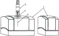
试验模块,并包括可拆卸地安装于上述传动机构与上述力度传感器相对的一端的第一试验组件、第二试验组件和第三试验组件,上述第一试验组件适用于在上述驱动杆的驱动下,对处于密闭工况下的被测样品进行压缩试验,上述第二试验组件适用于在上述驱动杆的驱动下,对处于密闭工况下的被测样品进行拉伸试验,上述第三试验组件适用于在上述驱动杆的驱动下,对处于液封工况下的被测样品进行拉伸试验;;A test module, and includes a first test assembly, a second test assembly and a third test assembly detachably installed at the end of the transmission mechanism opposite to the force sensor, the first test assembly is suitable for being driven by the drive rod , carry out a compression test on the tested sample under the airtight condition, the above-mentioned second test assembly is suitable for carrying out the tensile test on the test sample under the airtight condition driven by the above-mentioned drive rod, and the above-mentioned third test assembly It is suitable for carrying out tensile test on the tested sample under the condition of liquid seal under the driving of the above-mentioned driving rod;
其中,上述被测样品在上述试验模块中进行拉伸或压缩试验过程中,上述力度传感器获取上述驱动杆的受力变化数据,同时上述低场核磁共振谱仪获取被测样品的核磁共振数据,以获得被测样品的材料结构随受力变化的演变过程信息。Wherein, during the tensile or compression test of the tested sample in the above test module, the force sensor acquires the force change data of the driving rod, and the low-field nuclear magnetic resonance spectrometer acquires the nuclear magnetic resonance data of the tested sample, To obtain the evolution process information of the material structure of the tested sample as the force changes.
根据本发明的实施例,上述传动机构包括:According to an embodiment of the present invention, the above-mentioned transmission mechanism includes:
过渡套管,上述过渡套管的第一端可拆卸地安装于上述定位机构;以及a transition sleeve, the first end of the transition sleeve is detachably mounted on the positioning mechanism; and
引导管,上述引导管的第一端与上述过渡套管的第二端连接,上述引导管的第二端与上述试验模块连接,上述驱动杆可滑动地穿过上述过渡套管和上述引导管,并且上述驱动杆的第一端与上述力度传感器连接,上述驱动杆的第二端与上述试验模块连接。a guide tube, the first end of the guide tube is connected to the second end of the transition sleeve, the second end of the guide tube is connected to the test module, the drive rod can slide through the transition sleeve and the guide tube , and the first end of the driving rod is connected to the force sensor, and the second end of the driving rod is connected to the test module.
根据本发明的实施例,上述传动机构还包括:According to an embodiment of the present invention, the above-mentioned transmission mechanism also includes:
卡箍套管,安装于上述过渡套管的第一端,上述卡箍套管远离上述过渡套管的一端安装有多个卡爪;以及A clamp sleeve installed on the first end of the above-mentioned transition sleeve, and a plurality of claws are installed on the end of the above-mentioned clamp sleeve away from the above-mentioned transition sleeve; and
自锁套筒,套设于上述卡箍套管外,上述自锁套筒的第一端与上述过渡套管的第一端螺纹连接,上述驱动杆的第一端穿过上述自锁套筒和上述卡箍套管并与上述力度传感器连接,上述驱动杆的第二端与上述试验模块连接,上述自锁套筒内设置有锥形孔,在上述自锁套筒朝向上述过渡套管的方向旋紧过程中,上述锥形孔挤压多个上述卡爪,使得多个上述卡爪向上述驱动杆靠拢并将上述驱动杆锁紧,以阻止上述驱动杆与上述固定套管发生相对滑动。The self-locking sleeve is sleeved outside the clamp sleeve, the first end of the self-locking sleeve is screwed to the first end of the transition sleeve, and the first end of the driving rod passes through the self-locking sleeve It is connected with the above-mentioned clamp sleeve and the above-mentioned force sensor, the second end of the above-mentioned driving rod is connected with the above-mentioned test module, the above-mentioned self-locking sleeve is provided with a tapered hole, and the above-mentioned self-locking sleeve is facing the above-mentioned transition sleeve. During the direction tightening process, the above-mentioned tapered hole squeezes a plurality of the above-mentioned claws, so that the above-mentioned multiple claws move closer to the above-mentioned driving rod and lock the above-mentioned driving rod, so as to prevent the relative sliding between the above-mentioned driving rod and the above-mentioned fixed sleeve .
根据本发明的实施例,上述第一试验组件包括:According to an embodiment of the present invention, the above-mentioned first test assembly includes:
压缩外管,可拆卸地安装于上述引导管的第二端;以及a compression outer tube removably mounted to the second end of the guide tube; and
压缩滑块,可拆卸地安装于上述驱动杆的第二端,在上述驱动杆的驱动下,使得上述压缩滑块沿上述第一方向滑动,以压缩置于上述压缩外管底部的被测样品进行压缩试验。a compression slider, detachably installed on the second end of the above-mentioned driving rod, driven by the above-mentioned driving rod, the above-mentioned compression slider slides along the above-mentioned first direction, so as to compress the tested sample placed at the bottom of the above-mentioned compression outer tube Do a compression test.
根据本发明的实施例,上述第二试验组件包括:According to an embodiment of the present invention, the above-mentioned second test assembly includes:
常规拉伸外管,可拆卸地安装于上述引导管的第二端;a conventional stretched outer tube, detachably mounted on the second end of the guide tube;
常规拉伸滑块,可拆卸地安装于上述驱动杆的第二端,在上述驱动杆的驱动下,使得上述常规拉伸滑块沿上述第一方向滑动;以及A conventional stretching slider, detachably mounted on the second end of the above-mentioned driving rod, driven by the above-mentioned driving rod, making the above-mentioned conventional stretching slider slide along the above-mentioned first direction; and
第一拉伸组件,上述第一拉伸组件安装于上述常规拉伸外管的底部和上述常规拉伸滑块之间,上述第一拉伸组件的中部适用于放置被测样品,在上述常规拉伸滑块向着远离上述常规拉伸外管的底部移动过程中,上述第一拉伸组件沿上述第一方向拉伸被测样品进行拉伸试验。The first stretching assembly, the above-mentioned first stretching assembly is installed between the bottom of the above-mentioned conventional stretching outer tube and the above-mentioned conventional stretching slider, the middle part of the above-mentioned first stretching assembly is suitable for placing the sample to be tested, in the above-mentioned conventional During the movement of the stretching slider away from the bottom of the conventional stretching outer tube, the first stretching assembly stretches the sample to be tested along the first direction to perform a tensile test.
根据本发明的实施例,上述第三试验组件包括:According to an embodiment of the present invention, the above-mentioned third test assembly includes:
密闭拉伸外管,可拆卸地安装于上述引导管的第二端,上述密闭拉伸外管上设置有注液口,适用于向上述密闭拉伸外管内填充试验溶液;The airtight stretched outer tube is detachably installed on the second end of the above-mentioned guide tube, and the above-mentioned closed stretched outer tube is provided with a liquid injection port, which is suitable for filling the test solution into the above-mentioned airtight stretched outer tube;
密闭拉伸滑块,可拆卸地安装于上述驱动杆的第二端,在上述驱动杆的驱动下,使得上述密闭拉伸滑块沿上述第一方向滑动;以及The airtight stretching slider is detachably mounted on the second end of the driving rod, and driven by the driving rod, the airtight stretching slider slides along the first direction; and
第二拉伸组件,上述第二拉伸组件安装于上述密闭拉伸外管的底部和上述密闭拉伸滑块之间,上述第二拉伸组件的中部适用于放置被测样品,在上述密闭拉伸滑块向着远离上述密闭拉伸外管的底部移动过程中,上述第二拉伸组件沿上述第一方向拉伸被测样品进行拉伸试验。The second stretching assembly, the above-mentioned second stretching assembly is installed between the bottom of the above-mentioned closed stretching outer tube and the above-mentioned closed stretching slider, the middle part of the above-mentioned second stretching assembly is suitable for placing the sample to be tested, and the above-mentioned closed During the movement of the stretching slider away from the bottom of the closed stretching outer tube, the second stretching assembly stretches the tested sample along the first direction to perform a tensile test.
根据本发明的实施例,上述第一拉伸组件和上述第二拉伸组件中的每一个包括:According to an embodiment of the present invention, each of the above-mentioned first stretching assembly and the above-mentioned second stretching assembly includes:
第一拉杆,安装于上述常规拉伸外管或上述密闭拉伸外管的底部;以及a first tie rod mounted on the bottom of the conventional stretched outer tube or the sealed stretched outer tube; and
第二拉杆,安装于上述常规拉伸滑块或上述密闭拉伸滑块;The second pull rod is installed on the above-mentioned conventional stretching slider or the above-mentioned airtight stretching slider;
其中上述第一拉杆和上述第二拉杆沿第一方向延伸,上述第一拉杆和上述第二拉杆相互面对的一端分别安装有第一夹具和第二夹具,上述第一夹具和上述第二夹具适用于夹紧被测样品。Wherein the above-mentioned first pull rod and the above-mentioned second pull rod extend along the first direction, and the ends facing each other of the above-mentioned first pull rod and the above-mentioned second pull rod are respectively installed with a first clamp and a second clamp, and the above-mentioned first clamp and the above-mentioned second clamp are Suitable for clamping the sample to be tested.
根据本发明的实施例,上述驱动机构包括:According to an embodiment of the present invention, the above-mentioned drive mechanism includes:
壳体,安装于上述定位机构,上述壳体上设置有沿上述第一方向延伸的滑轨;A housing installed on the above-mentioned positioning mechanism, the above-mentioned housing is provided with a slide rail extending along the above-mentioned first direction;
驱动电机,安装于上述壳体上;The driving motor is installed on the above-mentioned housing;
丝杆,沿上述第一方向延伸,安装于上述驱动电机,并在上述驱动电机的驱动下转动;以及a screw rod extending along the first direction, mounted on the driving motor, and rotated under the driving of the driving motor; and
适配块,与上述丝杆螺纹连接,并可滑动地设置于上述滑轨内,在上述丝杆转动驱动下,上述滑轨阻止上述适配块与上述壳体发生相对转动,使得上述适配块沿上述丝杆往复移动,力度传感器安装在上述适配块。The adapter block is threadedly connected with the above-mentioned screw rod, and is slidably arranged in the above-mentioned slide rail. Driven by the rotation of the above-mentioned screw rod, the above-mentioned slide rail prevents the relative rotation between the above-mentioned adapter block and the above-mentioned housing, so that the above-mentioned adapter The block moves back and forth along the above-mentioned screw rod, and the force sensor is installed on the above-mentioned adapter block.
根据本发明的实施例,上述定位机构包括:According to an embodiment of the present invention, the above-mentioned positioning mechanism includes:
底座,安装于上述低场核磁共振谱仪;以及a base mounted on the above-mentioned low-field nuclear magnetic resonance spectrometer; and
导向管,安装于上述底座,并沿上述第一方向延伸,使得上述壳体的导向杆插设于上述导向管内;a guide tube installed on the base and extending along the first direction, so that the guide rod of the housing is inserted into the guide tube;
其中,上述导向杆上可转动地安装有定位套筒,上述导向管与上述定位套筒螺纹连接;Wherein, a positioning sleeve is rotatably installed on the above-mentioned guide rod, and the above-mentioned guide tube is threadedly connected with the above-mentioned positioning sleeve;
上述底座上设置有固定夹座,并包括:The above-mentioned base is provided with a fixing clip seat, and includes:
第一抱箍,安装于上述底座;The first hoop is installed on the base;
第二抱箍,与上述第一抱箍面对设置;以及The second hoop is arranged facing the first hoop; and
锁紧螺栓,穿过上述第一抱箍和上述第二抱箍,使得上述第一抱箍和上述第二抱箍将上述过渡套管夹紧固定。The locking bolt passes through the first hoop and the second hoop, so that the first hoop and the second hoop clamp and fix the transition sleeve.
根据本发明的实施例,上述适配块上设置有光电传感器,适用于获取适配块的位置信息。According to an embodiment of the present invention, the above-mentioned adapter block is provided with a photoelectric sensor, which is suitable for acquiring position information of the adapter block.
根据本发明提供的与低场核磁共振谱仪联用的模块化同步检测装置,在驱动机构的驱动下,驱动杆沿第一方向朝向试验模块滑动的过程中,对被测样品进行压缩试验,驱动杆沿第一方向向着远离试验模块滑动的过程中,对被测样品进行拉伸试验,同时力度传感器获取驱动杆的受力变化数据,低场核磁共振谱仪同步获取被测样品的核磁共振数据,以获得被测样品的材料结构随受力变化的演变过程信息;试验模块拆装更换便捷,根据被测样品选择不同的试验模块,达到在不同工况下对被测样品进行检测的效果,能够在高分子材料加工及服役过程中,实时检测高分子材料微观结构和动力学演变过程。According to the modular synchronous detection device used in conjunction with the low-field nuclear magnetic resonance spectrometer provided by the present invention, under the drive of the drive mechanism, the test sample is subjected to a compression test while the drive rod slides toward the test module along the first direction, During the process of the drive rod sliding away from the test module along the first direction, a tensile test is performed on the sample to be tested, while the force sensor acquires the force change data of the drive rod, and the low-field nuclear magnetic resonance spectrometer simultaneously acquires the nuclear magnetic resonance of the sample to be tested. Data to obtain the evolution process information of the material structure of the tested sample with the change of force; the test module is easy to disassemble and replace, and different test modules are selected according to the tested sample to achieve the effect of testing the tested sample under different working conditions , which can detect the microstructure and dynamic evolution of polymer materials in real time during the processing and service of polymer materials.
附图说明Description of drawings
图1是根据本发明实施例的与低场核磁共振谱仪联用的模块化同步检测装置的立体示意图;Fig. 1 is the three-dimensional schematic diagram of the modular synchronous detection device used in conjunction with the low-field nuclear magnetic resonance spectrometer according to the embodiment of the present invention;
图2是根据本发明实施例的与低场核磁共振谱仪联用的模块化同步检测装置的局部示意图;2 is a partial schematic diagram of a modular synchronous detection device used in conjunction with a low-field nuclear magnetic resonance spectrometer according to an embodiment of the present invention;
图3是根据本发明实施例的与低场核磁共振谱仪联用的模块化同步检测装置的突出显示定位机构的局部示意图;3 is a partial schematic diagram of a highlighted positioning mechanism of a modular synchronous detection device used in conjunction with a low-field nuclear magnetic resonance spectrometer according to an embodiment of the present invention;
图4是根据本发明实施例的与低场核磁共振谱仪联用的模块化同步检测装置的突出显示驱动机构的局部示意图;4 is a partial schematic diagram of a highlighted driving mechanism of a modular synchronous detection device used in conjunction with a low-field nuclear magnetic resonance spectrometer according to an embodiment of the present invention;
图5是根据本发明实施例的与低场核磁共振谱仪联用的模块化同步检测装置的突出显示力度传感器的局部示意图;5 is a partial schematic diagram of a highlighted force sensor of a modular synchronous detection device used in conjunction with a low-field nuclear magnetic resonance spectrometer according to an embodiment of the present invention;
图6是根据本发明实施例的与低场核磁共振谱仪联用的模块化同步检测装置的突出显示传动机构的分解示意图;6 is an exploded schematic diagram of a highlighted transmission mechanism of a modular synchronous detection device used in conjunction with a low-field nuclear magnetic resonance spectrometer according to an embodiment of the present invention;
图7是根据本发明实施例的与低场核磁共振谱仪联用的模块化同步检测装置的突出显示第一试验组件的局部示意图;7 is a partial schematic diagram highlighting the first test component of a modular synchronous detection device used in conjunction with a low-field nuclear magnetic resonance spectrometer according to an embodiment of the present invention;
图8是根据本发明实施例的与低场核磁共振谱仪联用的模块化同步检测装置的突出显示第二试验组件的局部示意图;Fig. 8 is a partial schematic diagram highlighting the second test component of a modular synchronous detection device used in conjunction with a low-field nuclear magnetic resonance spectrometer according to an embodiment of the present invention;
图9是根据本发明实施例的与低场核磁共振谱仪联用的模块化同步检测装置的突出显示第二试验组件的局部分解示意图;Fig. 9 is a partially exploded schematic diagram of a second test component highlighted in a modular synchronous detection device used in conjunction with a low-field nuclear magnetic resonance spectrometer according to an embodiment of the present invention;
图10是根据本发明实施例的与低场核磁共振谱仪联用的模块化同步检测装置的突出显示第三试验组件的局部示意图。10 is a partial schematic diagram highlighting a third test component of a modular synchronous detection device used with a low-field NMR spectrometer according to an embodiment of the present invention.
附图标记reference sign
1、低场核磁共振谱仪;2、定位机构;21、底座;22、导向管;23、固定夹座;231、第一抱箍;232、第二抱箍;233、锁紧螺栓;3、驱动机构;31、壳体;311、滑轨;312、导向杆;313、定位套筒;32、驱动电机;33、丝杆;34、适配块;35、光电传感器;4、传动机构;41、驱动杆;42、过渡套管;43、引导管;44、卡箍套管;441、卡爪;45、自锁套筒;451、锥形孔;5、试验模块;6、第一试验组件;61、压缩外管;62、压缩滑块;7、第二试验组件;71、常规拉伸外管;711、第一半管;712、第二半管;72、常规拉伸滑块;73、第一拉伸组件;731、第一拉杆;732、第二拉杆;733、第一夹具;734、第二夹具;8、第三试验组件;81、密闭拉伸外管;811、注液口;82、密闭拉伸滑块;83、第二拉伸组件;9、力度传感器。1. Low-field nuclear magnetic resonance spectrometer; 2. Positioning mechanism; 21. Base; 22. Guide tube; 23. Fixing clamp seat; 231. First hoop; 232. Second hoop; 233. Locking bolt; 3 , driving mechanism; 31, shell; 311, slide rail; 312, guide rod; 313, positioning sleeve; 32, driving motor; 33, screw rod; 34, adapter block; 35, photoelectric sensor; 4, transmission mechanism ;41, drive rod; 42, transition sleeve; 43, guide tube; 44, clamp sleeve; 441, claw; 45, self-locking sleeve; 451, tapered hole; 5, test module; 1st test component; 61. Compression outer tube; 62. Compression slider; 7. Second test component; 71. Conventional tension outer tube; 711. First half tube; 712. Second half tube; 72. Conventional tension Slider; 73, the first tensile component; 731, the first pull rod; 732, the second pull rod; 733, the first clamp; 734, the second clamp; 8, the third test component; 81, the airtight tensile outer tube; 811. Liquid injection port; 82. Airtight stretching slider; 83. Second stretching component; 9. Force sensor.
具体实施方式Detailed ways
为使本发明的目的、技术方案和优点更加清楚明白,以下结合具体实施例,并参照附图,对本发明作进一步的详细说明。In order to make the object, technical solution and advantages of the present invention clearer, the present invention will be further described in detail below in conjunction with specific embodiments and with reference to the accompanying drawings.
在此公开本发明结构实施例和方法的描述。应当了解,这并不意图将本发明限制在特定公开的实施例中,本发明可以通过使用其它特征,元件、方法和实施例来加以实施。不同实施例中的相似元件通常会标示相似的号码。如图1、图2和图5所示,本发明实施例提出一种与低场核磁共振谱仪联用的模块化同步检测装置,包括低场核磁共振谱仪1、定位机构2、驱动机构3、传动机构4、力度传感器9和试验模块5。Descriptions of structural embodiments and methods of the invention are disclosed herein. It should be understood that there is no intention to limit the invention to the particular disclosed embodiments, and that the invention can be practiced using other features, elements, methods and embodiments. Similar elements in different embodiments are generally labeled with similar numbers. As shown in Figure 1, Figure 2 and Figure 5, the embodiment of the present invention proposes a modular synchronous detection device used in conjunction with a low-field nuclear magnetic resonance spectrometer, including a low-field nuclear
定位机构2安装于低场核磁共振谱仪1;驱动机构3安装于定位机构2;传动机构4包括驱动杆41,驱动杆41部分地穿过定位机构2,以在驱动机构3的驱动下,沿第一方向相对于定位机构2往复直线滑动;力度传感器9安装于驱动杆41与驱动机构3之间,以检测驱动机构3施加在驱动杆41上的力。试验模块5包括可拆卸地安装于传动机构4与力度传感器9相对的一端的第一试验组件6、第二试验组件7和第三试验组件8,如图7所示,第一试验组件6适用于在驱动杆41的驱动下,对处于密闭工况下的被测样品进行压缩试验;如图8和9所示,第二试验组件7适用于在驱动杆41的驱动下,对处于密闭工况下的被测样品进行拉伸试验;如图10所示,第三试验组件8适用于在驱动杆41的驱动下,对处于液封工况下的被测样品进行拉伸试验。被测样品在试验模块5中进行拉伸或压缩试验过程中,力度传感器9获取驱动杆41的受力变化数据,同时低场核磁共振谱仪1获取被测样品的核磁共振数据,以获得被测样品的材料结构随受力变化的演变过程信息。The
根据本实施例提供的与低场核磁共振谱仪联用的模块化同步检测装置,被测样品放置于试验模块5内,在驱动机构3的驱动下,驱动杆41沿第一方向朝向试验模块5滑动的过程中,对被测样品进行压缩试验,驱动杆41沿第一方向向着远离试验模块5滑动的过程中,对被测样品进行拉伸试验,同时力度传感器9获取驱动杆41的受力变化数据,低场核磁共振谱仪1同步获取被测样品的核磁共振数据,以获得被测样品的材料结构随受力变化的演变过程信息;试验模块拆装更换便捷,根据被测样品选择不同的试验模块,达到在不同工况下对被测样品进行检测的效果,能够在高分子材料加工及服役过程中,实时检测高分子材料微观结构和动力学演变过程。在一种示例性实施例中,如图1和图3所示,定位机构2包括底座21和导向管22。底座21安装于低场核磁共振谱仪1;导向管22安装于底座21的顶部,并沿第一方向延伸,第一方向为竖直方向。导向管22设置有四个,绕底座21的中轴线均匀间隔分布,提升底座21的平衡性。According to the modularized synchronous detection device used in conjunction with the low-field nuclear magnetic resonance spectrometer provided in this embodiment, the sample to be tested is placed in the
在一种示例性实施例中,如图3和图4所示,驱动机构3包括壳体31、驱动电机32、丝杆33和适配块34。壳体31的底部面对导向管22处安装有导向杆312,导向杆312插设于导向管22内,导向杆312上可转动地安装有定位套筒313,导向管22与定位套筒313螺纹连接。导向杆312插入导向管22的过程中,导向管22对导向杆312进行导向,使得驱动机构3安装于定位机构2时能够同轴,提高了驱动机构3安装的精确度,减小拉伸或压缩试验的误差。In an exemplary embodiment, as shown in FIGS. 3 and 4 , the
壳体31内设置有沿第一方向延伸的滑轨311;驱动电机32安装于壳体31的顶部,本实施例中驱动电机32为伺服电机;丝杆33沿第一方向延伸,并通过联轴器安装于驱动电机32的输出轴上,使得丝杠在驱动电机32的驱动下转动。适配块34与丝杆33螺纹连接,并可滑动地设置于滑轨311内,在丝杆33转动驱动下,滑轨311阻止适配块34与壳体31发生相对转动,使得适配块34沿丝杆33往复移动,通过控制驱动电机32的转动速度和转动角度实现是配块运动的位移和速度的控制,速度范围为0.001mm/s-1mm/s。The
在一种示例性实施例中,如图4所示,适配块34上还设置有光电传感器35,适用于获取适配块34的位置信息,以对适配块34的空间位置定位,以对适配块34进行防撞保护。In an exemplary embodiment, as shown in FIG. 4 , a
根据本实施例提供的与低场核磁共振谱仪联用的模块化同步检测装置,驱动机构3启动后,驱动电机32带动丝杠转动,滑轨311阻止适配块34与壳体31发生相对转动,使得适配块34沿丝杆33和滑轨311在第一方向往复移动。According to the modular synchronous detection device used in conjunction with the low-field nuclear magnetic resonance spectrometer provided in this embodiment, after the
在一种示例性实施例中,如图3和图4所示,底座21上设置有固定夹座23,并包括第一抱箍231、第二抱箍232和锁紧螺栓233。第一抱箍231安装于底座21;第二抱箍232与第一抱箍231面对设置;锁紧螺栓233穿过第一抱箍231和第二抱箍232,以将第一抱箍231和第二抱箍232锁紧固定。在一种示例性实施例中,如图5和图6所示,力度传感器9螺纹连接于滑块的底部。传动机构4包括驱动杆41、过渡套管42、引导管43、卡箍套管44和自锁套筒45,驱动杆41沿第一方向延伸,驱动杆41的第一端螺纹连接于力度传感器9的底部,驱动杆41的第二端与试验模块5连接,结合图3所示,驱动杆41部分地穿过第一抱箍231和第二抱箍232之间,以在驱动机构3的驱动下,随滑块沿第一方向相对于定位机构2往复直线滑动。In an exemplary embodiment, as shown in FIG. 3 and FIG. 4 , the
过渡套管42的第一端置于第一抱箍231和第二抱箍232之间,旋紧锁紧螺栓233,使得第一抱箍231和第二抱箍232将过度套管夹紧,驱动杆41可滑动地穿过过渡套管42。引导管43的第一端与过渡套管42的第二端连接,引导管43的第二端与试验模块5连接,驱动杆41可滑动地穿过引导管43,引导管43的材料为氧化锆陶瓷或聚四氟乙烯,减小对低场核磁共振谱仪1的信号的干扰。The first end of the
卡箍套管44安装于过渡套管42的第一端,卡箍套管44远离过渡套管42的一端安装有多个卡爪441,多个卡爪441绕卡箍套管44的轴线均匀间隔分布,驱动杆41可滑动地穿过卡箍套管44。自锁套筒45套设于卡箍套管44外,自锁套筒45的第一端与过渡套管42的第一端螺纹连接,自锁套筒45内设置有锥形孔451,在自锁套筒45朝向过渡套管42的方向旋紧过程中,锥形孔451挤压多个卡爪441,使得多个卡爪441向驱动杆41靠拢并将驱动杆41锁紧,以阻止驱动杆41与固定套管发生相对滑动。The
根据本实施例提供的与低场核磁共振谱仪联用的模块化同步检测装置,驱动杆41随滑块移动而沿第一方向移动,过渡套管42和引导管43对驱动杆41移动进行导向,从而使被测样品在试验模块5内做拉伸或压缩试验。当试验过程中或试验结束后需要对驱动杆41锁定,以维持驱动杆41对被测样品的施力状态时,朝向过渡套管42的方向旋紧自锁套筒45,自锁套筒45的锥形孔451挤压多个卡爪441,使得多个卡爪441向驱动杆41靠拢并将驱动杆41锁紧,以阻止驱动杆41与固定套管发生相对滑动,从而锁定驱动杆41,以维持驱动杆41对被测样品的施力状态。在一种示例性实施例中,如图7所示,第一试验组件6包括压缩外管61和压缩滑块62。压缩外管61可拆卸地安装于引导管43的第二端,本实施例中压缩外管61与引导管43螺纹连接;压缩滑块62可拆卸地安装于驱动杆41的第二端,本实施例中压缩滑块62与驱动杆41螺纹连接,压缩滑块62还可以通过螺栓或卡件与驱动杆41连接。在驱动杆41的驱动下,压缩滑块62沿第一方向滑动,以压缩置于压缩外管61底部的被测样品进行压缩试验。According to the modular synchronous detection device used in conjunction with the low-field nuclear magnetic resonance spectrometer provided in this embodiment, the driving
在一种示例性实施例中,压缩外管61远离引导管43的一端螺纹连接有螺帽,螺帽将压缩外管61的端部密封。螺帽拆卸便捷,提高了压缩外管61清理的便捷性。In an exemplary embodiment, the end of the compression
根据本实施例提供的与低场核磁共振谱仪联用的模块化同步检测装置,对被测样品进行压缩试验时,被测样品放置于压缩外管61的底部,在驱动电机32的驱动下丝杠转动,从而带动适配块34、驱动杆41和压缩滑块62沿第一方向向着靠近压缩外管61的方向移动,压缩滑块62压缩置于压缩外管61底部的被测样品进行压缩试验,此时力度传感器9获取驱动杆41的受力变化数据,低场核磁共振谱仪1同步获取被测样品的核磁共振数据,以获得被测样品的材料结构随受力变化的演变过程信息,能够在高分子材料在压缩试验过程中,实时检测高分子材料微观结构和动力学演变过程。在一种示例性实施例中,如图8和图9所示,被测样品进行拉伸试验时,更换为第二试验组件7,第二试验组件7包括常规拉伸外管71、常规拉伸滑块72和第一拉伸组件73。常规拉伸外管71可拆卸地安装于引导管43的第二端,常规拉伸外管71包括第一半管711和第二半管712,第一半管711和第二半管712沿第一方向正对设置,第一半管711和第二半管712通过螺栓组合形成常规拉伸外管71;常规拉伸滑块72可拆卸地安装于驱动杆41的第二端,在驱动杆41的驱动下,使得常规拉伸滑块72沿第一方向滑动;第一拉伸组件73安装于常规拉伸外管71的底部和常规拉伸滑块72之间,第一拉伸组件73的中部适用于放置被测样品,在常规拉伸滑块72向着远离常规拉伸外管71的底部移动过程中,第一拉伸组件73沿第一方向拉伸被测样品进行拉伸试验。According to the modular synchronous detection device used in conjunction with the low-field nuclear magnetic resonance spectrometer provided in this embodiment, when the sample to be tested is subjected to a compression test, the sample to be tested is placed on the bottom of the compression
根据本实施例提供的与低场核磁共振谱仪联用的模块化同步检测装置,将被测样品放置于第一拉伸组件73时,旋松螺栓,将第一半管711与第二半管712分离,随后将被测样品放置于第一拉伸组件73的中部,接着将第一半管711和第二半管712用螺栓固定,常规拉伸外管71与引导管43的第二端螺纹连接,完成被测样品放置。在一种示例性实施例中,当被测样品是特殊功能薄膜时,例如可以作为偏光片使用的PVA薄膜,在溶液流延成型加工过程中需要分别在硼酸溶液及碘溶液当中进行浸润和碘染。被测样品在溶液中进行拉伸试验时,更换为第三试验组件8,如图10所示,第三试验组件8包括密闭拉伸外管81、密闭拉伸滑块82和第二拉伸组件83。密闭拉伸外管81可拆卸地安装于引导管43的第二端,密闭拉伸外管81的底端螺纹连接有螺帽,螺帽拆装便捷,便于安装被测样品,密闭拉伸外管81上设置有注液口811,适用于向密闭拉伸外管81内填充试验溶液,随后利用聚四氟乙烯顶丝封堵注液孔,防止液体外溢;密闭拉伸滑块82可拆卸地安装于驱动杆41的第二端,在驱动杆41的驱动下,使得密闭拉伸滑块82沿第一方向滑动。第二拉伸组件83位于密闭拉伸外管81内并安装于密闭拉伸外管81的螺帽和密闭拉伸滑块82之间,第二拉伸组件83的中部适用于放置被测样品,在密闭拉伸滑块82向着远离密闭拉伸外管81的底部移动过程中,第二拉伸组件83沿第一方向拉伸被测样品进行拉伸试验。According to the modular synchronous detection device used in conjunction with the low-field nuclear magnetic resonance spectrometer provided in this embodiment, when the sample to be tested is placed on the
在一种示例性实施例中,如图9和图10所示,第一拉伸组件73和第二拉伸组件83中的每一个包括第一拉杆731、第二拉杆732、第一夹具733和第二夹具734。第一拉杆731安装于常规拉伸外管71或密闭拉伸外管81的底部的卡槽内;第二拉杆732安装于常规拉伸滑块72或密闭拉伸滑块82;其中第一拉杆731和第二拉杆732沿第一方向延伸,第一拉杆731和第二拉杆732相互面对的一端分别安装有第一夹具733和第二夹具734,第一夹具733和第二夹具734适用于夹紧被测样品。In an exemplary embodiment, as shown in FIGS. 9 and 10 , each of the
根据本实施例提供的与低场核磁共振谱仪联用的模块化同步检测装置,对被测样品进行拉伸试验时,被测样品放置于第一夹具733和第二夹具734处,在驱动电机32的驱动下丝杠转动,从而带动适配块34和驱动杆41沿第一方向向上移动,驱动杆41带动常规拉伸滑块72或密闭拉伸滑块82移动,从而带动第一拉杆731和第一夹具733向上移动,第一夹具733和第二夹具734相互远离,被测样品产生单轴形变进行拉伸试验,此时力度传感器9获取驱动杆41的受力变化数据,低场核磁共振谱仪1同步获取被测样品的核磁共振数据,以获得被测样品的材料结构随受力变化的演变过程信息,能够在高分子材料在拉伸试验过程中,实时检测高分子材料微观结构和动力学演变过程。According to the modularized synchronous detection device used in conjunction with the low-field nuclear magnetic resonance spectrometer provided in this embodiment, when the sample to be tested is subjected to a tensile test, the sample to be tested is placed at the
根据本实施例提供的与低场核磁共振谱仪联用的模块化同步检测装置,在对被测样品进行压缩或拉伸试验时,被测样品放置于试验模块5内,在驱动机构3的驱动下,驱动杆41沿第一方向朝向试验模块5滑动的过程中,对被测样品进行压缩试验,驱动杆41沿第一方向向着远离试验模块5滑动的过程中,对被测样品进行拉伸试验,同时力度传感器9获取驱动杆41的受力变化数据,低场核磁共振谱仪1同步获取被测样品的核磁共振数据,以获得被测样品的材料结构随受力变化的演变过程信息;试验模块拆装更换便捷,根据被测样品选择不同的试验模块,达到在不同工况下对被测样品进行检测的效果,能够在高分子材料加工及服役过程中,实时检测高分子材料微观结构和动力学演变过程。According to the modular synchronous detection device used in conjunction with the low-field nuclear magnetic resonance spectrometer provided in this embodiment, when the sample to be tested is subjected to a compression or tensile test, the sample to be tested is placed in the
上述具体实施例,对本发明的目的、技术方案和有益效果进行了进一步详细说明,应理解的是,以上上述仅为本发明的具体实施例而已,并不用于限制本发明,凡在本发明的精神和原则之内,所做的任何修改、等同替换、改进等,均应包含在本发明的保护范围之内。The above-mentioned specific embodiments have further described the purpose, technical solutions and beneficial effects of the present invention in detail. It should be understood that the above-mentioned are only specific embodiments of the present invention, and are not intended to limit the present invention. Within the spirit and principles, any modifications, equivalent replacements, improvements, etc., shall be included within the protection scope of the present invention.
Claims (8)
Translated fromChinesePriority Applications (1)
| Application Number | Priority Date | Filing Date | Title |
|---|---|---|---|
| CN202211243620.9ACN115308251B (en) | 2022-10-12 | 2022-10-12 | Modularized synchronous detection device combined with low-field nuclear magnetic resonance spectrometer |
Applications Claiming Priority (1)
| Application Number | Priority Date | Filing Date | Title |
|---|---|---|---|
| CN202211243620.9ACN115308251B (en) | 2022-10-12 | 2022-10-12 | Modularized synchronous detection device combined with low-field nuclear magnetic resonance spectrometer |
Publications (2)
| Publication Number | Publication Date |
|---|---|
| CN115308251A CN115308251A (en) | 2022-11-08 |
| CN115308251Btrue CN115308251B (en) | 2023-07-14 |
Family
ID=83867995
Family Applications (1)
| Application Number | Title | Priority Date | Filing Date |
|---|---|---|---|
| CN202211243620.9AActiveCN115308251B (en) | 2022-10-12 | 2022-10-12 | Modularized synchronous detection device combined with low-field nuclear magnetic resonance spectrometer |
Country Status (1)
| Country | Link |
|---|---|
| CN (1) | CN115308251B (en) |
Families Citing this family (1)
| Publication number | Priority date | Publication date | Assignee | Title |
|---|---|---|---|---|
| CN118190630B (en)* | 2024-05-14 | 2024-09-10 | 中国科学技术大学 | Single-side nuclear magnetic resonance combined angle-variable multi-axis deformation instrument |
Citations (9)
| Publication number | Priority date | Publication date | Assignee | Title |
|---|---|---|---|---|
| SU1283637A1 (en)* | 1985-05-20 | 1987-01-15 | Институт Химической Физики Ан Ссср | Device for investigating mechanical deformation of solids |
| JPH10319178A (en)* | 1997-05-16 | 1998-12-04 | Kawasaki Heavy Ind Ltd | Method and apparatus for testing mechanical properties of structural materials under neutron irradiation in reactor |
| JP2002318180A (en)* | 2001-04-23 | 2002-10-31 | Toyo Seiki Seisakusho:Kk | Uniaxial bidirectional tensile tester and sample central part measuring device using it |
| JP2005338026A (en)* | 2004-05-31 | 2005-12-08 | Toshiba Corp | Small material testing apparatus and material testing method |
| CN105092378A (en)* | 2015-08-13 | 2015-11-25 | 河南科技大学 | Tensile test device |
| CN206208651U (en)* | 2016-11-08 | 2017-05-31 | 深圳万测试验设备有限公司 | Biaxial tension-compression strength device |
| CN108195868A (en)* | 2017-12-26 | 2018-06-22 | 桂林理工大学 | Simulate nmr experiments device and its application method during swelled ground drying and watering cycle under load action |
| CN210014995U (en)* | 2019-05-23 | 2020-02-04 | 安徽科技学院 | Simple horizontal tensile test device for magnetic signal measurement |
| CN114942185A (en)* | 2022-04-13 | 2022-08-26 | 北京理工大学 | In-situ mechanical loading testing machine, testing system and testing method |
Family Cites Families (12)
| Publication number | Priority date | Publication date | Assignee | Title |
|---|---|---|---|---|
| CN100510696C (en)* | 2006-12-01 | 2009-07-08 | 中国科学院海洋研究所 | Apparatus and method for researching erosion sensibility of stress in air under the condition of dynamic load |
| JP4788622B2 (en)* | 2007-02-09 | 2011-10-05 | 株式会社島津製作所 | Material testing machine |
| CN101746054B (en)* | 2008-12-02 | 2012-05-30 | 中国科学院国家天文台 | A manual stretching machine for thin film wave plate and method for making wave plate with it |
| TWI525184B (en)* | 2011-12-16 | 2016-03-11 | 拜歐菲樂Ip有限責任公司 | Cryogenic injection compositions, systems and methods for cryogenically modulating flow in a conduit |
| US9696391B2 (en)* | 2012-05-07 | 2017-07-04 | Academia Sinica | High speed sample transportation apparatus in a superconducting magnet and transporting method thereof |
| CN105675396B (en)* | 2016-02-01 | 2018-04-24 | 上海交通大学 | Multi-functional single shaft tensile test apparatus for microstructure original position online observation |
| CN107063889B (en)* | 2017-03-27 | 2023-04-28 | 中国科学技术大学 | A Creep Tensile Apparatus Combined with X-ray Scattering and Its Experimental Method |
| CN107991175A (en)* | 2017-11-20 | 2018-05-04 | 西北工业大学 | A kind of room temperature for high pressure torsion tensile sample, cryogenic tensile fixture |
| CN109556963A (en)* | 2019-01-24 | 2019-04-02 | 西安市亚星土木仪器有限公司 | Pitch tension failure toughness tester |
| CN110031035B (en)* | 2019-03-25 | 2024-01-16 | 中国电子产品可靠性与环境试验研究所((工业和信息化部电子第五研究所)(中国赛宝实验室)) | Optical fiber sensor stretching, compressing, vibrating and alternating damp-heat fatigue testing device and testing method thereof |
| CN112113844A (en)* | 2020-09-25 | 2020-12-22 | 中国科学院高能物理研究所 | In-situ mechanical performance testing device and testing method |
| CN113654913B (en)* | 2021-09-01 | 2022-05-13 | 中国科学技术大学 | Low-field nuclear magnetic resonance in-situ stretching rheological detection system |
- 2022
- 2022-10-12CNCN202211243620.9Apatent/CN115308251B/enactiveActive
Patent Citations (9)
| Publication number | Priority date | Publication date | Assignee | Title |
|---|---|---|---|---|
| SU1283637A1 (en)* | 1985-05-20 | 1987-01-15 | Институт Химической Физики Ан Ссср | Device for investigating mechanical deformation of solids |
| JPH10319178A (en)* | 1997-05-16 | 1998-12-04 | Kawasaki Heavy Ind Ltd | Method and apparatus for testing mechanical properties of structural materials under neutron irradiation in reactor |
| JP2002318180A (en)* | 2001-04-23 | 2002-10-31 | Toyo Seiki Seisakusho:Kk | Uniaxial bidirectional tensile tester and sample central part measuring device using it |
| JP2005338026A (en)* | 2004-05-31 | 2005-12-08 | Toshiba Corp | Small material testing apparatus and material testing method |
| CN105092378A (en)* | 2015-08-13 | 2015-11-25 | 河南科技大学 | Tensile test device |
| CN206208651U (en)* | 2016-11-08 | 2017-05-31 | 深圳万测试验设备有限公司 | Biaxial tension-compression strength device |
| CN108195868A (en)* | 2017-12-26 | 2018-06-22 | 桂林理工大学 | Simulate nmr experiments device and its application method during swelled ground drying and watering cycle under load action |
| CN210014995U (en)* | 2019-05-23 | 2020-02-04 | 安徽科技学院 | Simple horizontal tensile test device for magnetic signal measurement |
| CN114942185A (en)* | 2022-04-13 | 2022-08-26 | 北京理工大学 | In-situ mechanical loading testing machine, testing system and testing method |
Non-Patent Citations (2)
| Title |
|---|
| Magnetic Field Integral Measurements With Stretched Wire and Hall Probe Methods;Mona Gehlot 等;IEEE TRANSACTIONS ON MAGNETICS;第第56卷卷(第第5期期);3100408* |
| 在线同步对称拉伸仪的研发及应用;周天楠;刘齐锐;蔡绪福;杨昌跃;;实验科学与技术(04);第35-38+43页* |
Also Published As
| Publication number | Publication date |
|---|---|
| CN115308251A (en) | 2022-11-08 |
Similar Documents
| Publication | Publication Date | Title |
|---|---|---|
| CN107607390B (en) | Variable-temperature tension-torsion composite load material mechanical property in-situ test device and method | |
| CN115308251B (en) | Modularized synchronous detection device combined with low-field nuclear magnetic resonance spectrometer | |
| CN106371043B (en) | Superconducting tape test device | |
| CN106680079A (en) | Piezoelectric stack direct driving type macro-micro combined biaxial stretching-fatigue testing system | |
| CN107607410A (en) | Portable alternating temperature original position tension/compression testing device | |
| CN209182160U (en) | A kind of intensity detecting device for leather | |
| CN111413360A (en) | In-situ stress corrosion test device for X-ray microscope | |
| CN106404539B (en) | A test method to achieve uniform uniaxial tension | |
| CN113654913B (en) | Low-field nuclear magnetic resonance in-situ stretching rheological detection system | |
| CN106989988A (en) | A kind of device that uniaxial pressure is converted to multidirectional pulling force and pressure | |
| CN206330835U (en) | A Microscope Extensometer Adapted to an Optical Microscope | |
| CN113533034B (en) | Soil tensile test device and soil tensile test method | |
| CN104697850B (en) | Device capable of applying multidirectional tensile loads to fabric materials | |
| CN103528889B (en) | An In-Situ Tensile Tester Based on Inchworm Piezoelectric Actuator | |
| CN209102518U (en) | A kind of reinforced bar mechanical connector tensile strength test device | |
| CN206479407U (en) | The grand micro- biaxial stretch-formed fatigue test system of combination of piezoelectric stack direct-driving type | |
| CN220084541U (en) | DIC strain measurement auxiliary miniature biaxial stretching testing machine | |
| CN111122342A (en) | Vacuum Variable Temperature Environment Loading Device for Neutron Stress Spectrometer | |
| CN209387400U (en) | Automobile wire harness detection equipment | |
| CN112858014B (en) | Axial force uniform distribution concentric fixture tensile testing machine | |
| CN115615826A (en) | Tension-shear coupling test device and test method for a test piece | |
| CN110987645A (en) | Rigid-flexible composite true triaxial loading device for solving stress concentration and soil extrusion problems | |
| CN110346391A (en) | A kind of multaxial stress loading experimental apparatus for neutron diffraction measurement | |
| CN206056934U (en) | A kind of easy reciprocal non-percussion load charger | |
| CN202101892U (en) | Novel hydraulic universal testing machine |
Legal Events
| Date | Code | Title | Description |
|---|---|---|---|
| PB01 | Publication | ||
| PB01 | Publication | ||
| SE01 | Entry into force of request for substantive examination | ||
| SE01 | Entry into force of request for substantive examination | ||
| GR01 | Patent grant | ||
| GR01 | Patent grant |