CN115307551A - Anti-interference multichannel optical fiber displacement measuring device - Google Patents
Anti-interference multichannel optical fiber displacement measuring deviceDownload PDFInfo
- Publication number
- CN115307551A CN115307551ACN202210979284.8ACN202210979284ACN115307551ACN 115307551 ACN115307551 ACN 115307551ACN 202210979284 ACN202210979284 ACN 202210979284ACN 115307551 ACN115307551 ACN 115307551A
- Authority
- CN
- China
- Prior art keywords
- optical fiber
- fiber
- sensing
- probe
- channel
- Prior art date
- Legal status (The legal status is an assumption and is not a legal conclusion. Google has not performed a legal analysis and makes no representation as to the accuracy of the status listed.)
- Pending
Links
Images


Classifications
- G—PHYSICS
- G01—MEASURING; TESTING
- G01B—MEASURING LENGTH, THICKNESS OR SIMILAR LINEAR DIMENSIONS; MEASURING ANGLES; MEASURING AREAS; MEASURING IRREGULARITIES OF SURFACES OR CONTOURS
- G01B11/00—Measuring arrangements characterised by the use of optical techniques
- G01B11/02—Measuring arrangements characterised by the use of optical techniques for measuring length, width or thickness
Landscapes
- Physics & Mathematics (AREA)
- General Physics & Mathematics (AREA)
- Length Measuring Devices By Optical Means (AREA)
Abstract
Description
Translated fromChinese技术领域technical field
本发明涉及光纤位移测量技术领域,尤其涉及一种抗干扰型多通道光纤位移测量装置。The invention relates to the technical field of optical fiber displacement measurement, in particular to an anti-interference type multi-channel optical fiber displacement measurement device.
背景技术Background technique
位移作为非常常见的物理参量,在现代科技中具有十分广泛的应用,如精密加工,自动化制造,大型建筑的健康监测等领域,位移测量技术都具有十分重要的意义。As a very common physical parameter, displacement has a wide range of applications in modern science and technology, such as precision machining, automated manufacturing, and health monitoring of large buildings. Displacement measurement technology is of great significance.
目前的位移测量主要包括接触式和非接触式两种,接触式以拉杆或拉线式位移计为代表,非接触式则包括电感式、电容式、光电式、超声波等位移测量技术,其中光电式最具发展潜力,包含激光位移测量技术,光纤位移测量技术等,具备结构简单,较容易实现高精度、大量程等优点。The current displacement measurement mainly includes contact type and non-contact type. The contact type is represented by a rod or wire displacement meter, and the non-contact type includes inductive, capacitive, photoelectric, ultrasonic and other displacement measurement technologies. Among them, photoelectric The most potential for development, including laser displacement measurement technology, optical fiber displacement measurement technology, etc., has the advantages of simple structure, easy to achieve high precision and large range.
反射型光纤位移测量技术的基本原理如图1所示,由光纤光源1、探测器21、发送光纤14和接收光纤13组成。光纤光源1通过发送光纤14将光打到被测面,接收光纤13接收其反射的光并送入探测器21,当被测面发生位移时,探测器21接收到的信号将发生对应变化,由此可以解算出被测面的位移量。The basic principle of the reflective optical fiber displacement measurement technology is shown in FIG. 1 , which consists of a fiber
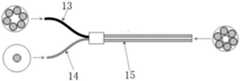
上述技术经过不断发展,接收光纤13数量扩展,并将光纤按照一定形状排列,制作成光纤束15,一路发送,多路接收,进一步增强了接收光信号,提升了信噪比。如图2所示为Y型分叉型光纤束,左右两侧分别为对应光纤的截面图,左侧分别为发送和接收端,右侧为光纤束探测端。With the continuous development of the above technology, the number of receiving
上述技术方案存在以下缺点:There is following shortcoming in above-mentioned technical scheme:
1.被测物体表面粗糙不平,发射光纤发射到被测表面的光随机发散,导致当前测量通道的光能减小,同时,多通道测量时,附近通道的光能增大,最终导致测量误差增大;1. The surface of the measured object is rough and uneven, and the light emitted by the emitting fiber to the measured surface randomly diverges, resulting in a decrease in the light energy of the current measurement channel. At the same time, during multi-channel measurement, the light energy of nearby channels increases, which eventually leads to measurement errors. increase;
2.由于光纤发射的光呈一定角度出射,导致一部分光反射到附近测量通道,致使其接受到的光能增大。2. Since the light emitted by the optical fiber exits at a certain angle, part of the light is reflected to the nearby measurement channel, resulting in an increase in the light energy it receives.
以上两种情况都容易在多通道、长距离测量时造成较大测量误差。The above two situations are easy to cause large measurement errors in multi-channel and long-distance measurement.
因此需要研发出一种抗干扰型多通道光纤位移测量装置来解决上述问题。Therefore, it is necessary to develop an anti-interference multi-channel optical fiber displacement measuring device to solve the above problems.
发明内容Contents of the invention
本发明的目的就在于为了解决上述问题设计了一种抗干扰型多通道光纤位移测量装置。The object of the present invention is to design an anti-interference type multi-channel optical fiber displacement measuring device in order to solve the above problems.
本发明通过以下技术方案来实现上述目的:The present invention achieves the above object through the following technical solutions:
一种抗干扰型多通道光纤位移测量装置,包括:An anti-interference multi-channel optical fiber displacement measuring device, comprising:
至少两路的光纤通道结构;每路光纤通道结构包括光纤耦合器、传感光纤、光电转换器、传感光纤探头、反射镜片;光纤耦合器的输出端与传感光纤的输入端连接,传感光纤的探测端与传感光纤探头连接,传感光纤探头作用于反射镜片,反射镜片安装在被测物上,传感光纤的输出端与光电转换器的输入端连接,光电转换器的输出端与信号调理电路的输入端连接;At least two fiber channel structures; each fiber channel structure includes a fiber coupler, a sensing fiber, a photoelectric converter, a sensing fiber probe, and a reflector; the output end of the fiber coupler is connected to the input end of the sensing fiber, and the The detection end of the sensing fiber is connected to the sensing fiber probe, the sensing fiber probe acts on the reflector, the reflector is installed on the measured object, the output end of the sensing fiber is connected to the input end of the photoelectric converter, and the output of the photoelectric converter The terminal is connected to the input terminal of the signal conditioning circuit;
光纤分路器;光纤分路器的接收端接收光纤光源,光纤分路器的至少两个的发送端分别于至少两路的光纤通道结构内的光纤耦合器的输入端连接;Optical fiber splitter; the receiving end of the optical fiber splitter receives the optical fiber light source, and at least two sending ends of the optical fiber splitter are respectively connected to the input ends of the fiber couplers in at least two fiber channel structures;
信号调理电路;Signal conditioning circuit;
高速采集卡;信号调理电路的输出端与高速采集卡的输入端连接;A high-speed acquisition card; the output end of the signal conditioning circuit is connected to the input end of the high-speed acquisition card;
计算机;高速采集卡的输出端与计算机连接。Computer; the output end of the high-speed acquisition card is connected with the computer.
具体地,传感光纤包括光能输出口、光源输入口、接收光纤、发送光纤,接收光纤的第一端通过光能输出口与光电转换器的输入端连接,接收光纤的第二端置于传感光纤探头内;发送光纤的第一端通过光源输入口与光纤耦合器的输出端连接,发送光纤的第二端置于传感光纤探头内。Specifically, the sensing optical fiber includes an optical energy output port, a light source input port, a receiving optical fiber, and a transmitting optical fiber. The first end of the receiving optical fiber is connected to the input end of the photoelectric converter through the optical energy output port, and the second end of the receiving optical fiber is placed Inside the sensing fiber probe; the first end of the sending fiber is connected to the output end of the fiber coupler through the light source input port, and the second end of the sending fiber is placed in the sensing fiber probe.
优选地,接收光纤和发送光纤构成Y型分叉结构,接收光纤的第一端和发送光纤的第一端分开设置。Preferably, the receiving optical fiber and the sending optical fiber form a Y-shaped bifurcated structure, and the first end of the receiving optical fiber and the first end of the sending optical fiber are arranged separately.
具体地,接收光纤和发送光纤组合成光纤束。Specifically, the receiving optical fiber and the transmitting optical fiber are combined into an optical fiber bundle.
进一步地,传感光纤探头包括探头金属保护壳,发送光纤的第二端和接收光纤的第二端置于探头金属保护壳内。Further, the sensing optical fiber probe includes a metal protective shell of the probe, and the second end of the transmitting optical fiber and the second end of the receiving optical fiber are placed in the metal protective shell of the probe.
更进一步地,传感光纤探头还包括微光纤准直器,微光纤准直器安装在发送光纤的第二端上。Furthermore, the sensing optical fiber probe also includes a micro-fiber collimator installed on the second end of the sending optical fiber.
优选地,发送光纤为单模光纤,接收光纤为多模光纤。Preferably, the transmitting optical fiber is a single-mode optical fiber, and the receiving optical fiber is a multi-mode optical fiber.
更优选地,接收光纤的多根子光纤均匀围绕发送光纤设置。More preferably, the plurality of sub-fibers of the receiving fiber are evenly arranged around the sending fiber.
本发明的有益效果在于:The beneficial effects of the present invention are:
1、传统Y型分叉型传感光纤探测端直接使用光纤进行光的发射,光呈一定角度发散,当进行多通道测量且间隔较近时,相邻通道间易发生串扰,本申请以微光纤准直器作为发射端面的传感光纤结构,能有效控制反射光斑尺寸,解决上述问题,提升工程应用的可行性;1. The traditional Y-type bifurcated sensor optical fiber detection end directly uses optical fiber to emit light, and the light diverges at a certain angle. When multi-channel measurement is performed and the distance is relatively close, crosstalk is prone to occur between adjacent channels. This application uses a micro As the sensing fiber structure of the emitting end face, the fiber collimator can effectively control the reflected spot size, solve the above problems, and improve the feasibility of engineering applications;
2、本申请采用反射镜片配合检测的传感光纤,解决被测物表面粗糙度影响问题。2. This application uses a reflective lens to cooperate with the sensing fiber for detection to solve the problem of the surface roughness of the measured object.
附图说明Description of drawings
图1是现有技术结构示意图一;Fig. 1 is a schematic diagram of the structure of the prior art;
图2是现有技术结构示意图二;Fig. 2 is the structural schematic diagram II of the prior art;
图3是本申请结构示意图;Fig. 3 is a schematic diagram of the structure of the application;
图4是本申请中传感光纤的结构示意图;Fig. 4 is the structural representation of sensing fiber in the present application;
图5是本申请中接收光纤的截面示意图;Fig. 5 is a schematic cross-sectional view of the receiving optical fiber in the present application;
图6是本申请中发送光纤的截面示意图;Fig. 6 is a schematic cross-sectional view of the transmitting optical fiber in the present application;
图7是本申请中光纤探头的截面示意图;Fig. 7 is a cross-sectional schematic diagram of an optical fiber probe in the present application;
图8是本申请中传感光纤的的原理图;Fig. 8 is a schematic diagram of sensing optical fiber in the present application;
附图标记说明Explanation of reference signs
1-光纤光源,2-光纤分路器,3-光纤耦合器,4-传感光纤,5-光电转换器,6-传感光纤探头,7-信号调理电路,8-高速采集卡,9-计算机,10-反射镜片,11-光能输出口,12-光源输入口,13-接收光纤,14-发送光纤,15-光纤束,16-微光纤准直器,61-探头金属保护壳;21-探测器。1-Fiber optic light source, 2-Fiber optic splitter, 3-Fiber optic coupler, 4-Sensing fiber, 5-Photoelectric converter, 6-Sensing fiber probe, 7-Signal conditioning circuit, 8-High-speed acquisition card, 9 -computer, 10-reflector, 11-light energy output port, 12-light source input port, 13-receiving optical fiber, 14-sending optical fiber, 15-fiber bundle, 16-micro-fiber collimator, 61-probe metal protective case ; 21 - Detector.
具体实施方式Detailed ways
为使本发明实施例的目的、技术方案和优点更加清楚,下面将结合本发明实施例中的附图,对本发明实施例中的技术方案进行清楚、完整地描述。显然,所描述的实施例是本发明一部分实施例,而不是全部的实施例。通常在此处附图中描述和示出的本发明实施例的组件可以以各种不同的配置来布置和设计。In order to make the purpose, technical solutions and advantages of the embodiments of the present invention more clear, the technical solutions in the embodiments of the present invention will be clearly and completely described below in conjunction with the drawings in the embodiments of the present invention. Apparently, the described embodiments are some, but not all, embodiments of the present invention. The components of the embodiments of the invention generally described and illustrated in the figures herein may be arranged and designed in a variety of different configurations.
因此,以下对在附图中提供的本发明的实施例的详细描述并非旨在限制要求保护的本发明的范围,而是仅仅表示本发明的选定实施例。基于本发明中的实施例,本领域普通技术人员在没有作出创造性劳动前提下所获得的所有其他实施例,都属于本发明保护的范围。Accordingly, the following detailed description of the embodiments of the invention provided in the accompanying drawings is not intended to limit the scope of the claimed invention, but merely represents selected embodiments of the invention. Based on the embodiments of the present invention, all other embodiments obtained by persons of ordinary skill in the art without creative efforts fall within the protection scope of the present invention.
应注意到:相似的标号和字母在下面的附图中表示类似项,因此,一旦某一项在一个附图中被定义,则在随后的附图中不需要对其进行进一步定义和解释。It should be noted that like numerals and letters denote similar items in the following figures, therefore, once an item is defined in one figure, it does not require further definition and explanation in subsequent figures.
在本发明的描述中,需要理解的是,术语“上”、“下”、“内”、“外”、“左”、“右”等指示的方位或位置关系为基于附图所示的方位或位置关系,或者是该发明产品使用时惯常摆放的方位或位置关系,或者是本领域技术人员惯常理解的方位或位置关系,仅是为了便于描述本发明和简化描述,而不是指示或暗示所指的设备或元件必须具有特定的方位、以特定的方位构造和操作,因此不能理解为对本发明的限制。In the description of the present invention, it should be understood that the orientations or positional relationships indicated by the terms "upper", "lower", "inner", "outer", "left", "right" etc. are based on those shown in the accompanying drawings. Orientation or positional relationship, or the orientation or positional relationship that is usually placed when the product of the invention is used, or the orientation or positional relationship that is commonly understood by those skilled in the art, is only for the convenience of describing the present invention and simplifying the description, rather than indicating or It should not be construed as limiting the invention by implying that a referenced device or element must have a particular orientation, be constructed, and operate in a particular orientation.
此外,术语“第一”、“第二”等仅用于区分描述,而不能理解为指示或暗示相对重要性。In addition, the terms "first", "second", etc. are only used for distinguishing descriptions, and should not be construed as indicating or implying relative importance.
在本发明的描述中,还需要说明的是,除非另有明确的规定和限定,“设置”、“连接”等术语应做广义理解,例如,“连接”可以是固定连接,也可以是可拆卸连接,或一体地连接;可以是机械连接,也可以是电连接;可以是直接连接,也可以通过中间媒介间接连接,可以是两个元件内部的连通。对于本领域的普通技术人员而言,可以根据具体情况理解上述术语在本发明中的具体含义。In the description of the present invention, it should also be noted that, unless otherwise specified and limited, terms such as "setting" and "connection" should be understood in a broad sense. For example, "connection" can be a fixed connection or a Detachable connection, or integral connection; it can be mechanical connection or electrical connection; it can be direct connection or indirect connection through an intermediary, and it can be the internal communication of two components. Those of ordinary skill in the art can understand the specific meanings of the above terms in the present invention according to specific situations.
下面结合附图,对本发明的具体实施方式进行详细说明。The specific implementation manners of the present invention will be described in detail below in conjunction with the accompanying drawings.
如图3所示,一种抗干扰型多通道光纤位移测量装置,包括:As shown in Figure 3, an anti-interference multi-channel optical fiber displacement measurement device includes:
至少两路的光纤通道结构(图3中示出的是两路光纤通道结构的情况);每路光纤通道结构包括光纤耦合器3、传感光纤4、光电转换器5、传感光纤探头6、反射镜片10;光纤耦合器3的输出端与传感光纤4的输入端连接,传感光纤4的探测端与传感光纤探头6连接,传感光纤探头6作用于反射镜片10,反射镜片10安装在被测物上,传感光纤4的输出端与光电转换器5的输入端连接,光电转换器5的输出端与信号调理电路7的输入端连接;At least two-way fiber channel structure (shown in Figure 3 is the situation of two-way fiber channel structure); each fiber channel structure includes
光纤分路器2;光纤分路器2的接收端接收光纤13光源1,光纤分路器2的至少两个的发送端分别于至少两路的光纤通道结构内的光纤耦合器3的输入端连接;
信号调理电路7;
高速采集卡8;信号调理电路7的输出端与高速采集卡8的输入端连接;High-
计算机9;高速采集卡8的输出端与计算机9连接。
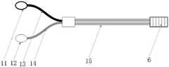
如图4所示,传感光纤4包括光能输出口11、光源输入口12、接收光纤13、发送光纤14,接收光纤13的第一端通过光能输出口11与光电转换器5的输入端连接,接收光纤13的第二端置于传感光纤探头6内;发送光纤14的第一端通过光源输入口12与光纤耦合器3的输出端连接,发送光纤14的第二端置于传感光纤探头6内。As shown in Figure 4, the
如图4所示,接收光纤13和发送光纤14构成Y型分叉结构,接收光纤13的第一端和发送光纤14的第一端分开设置。As shown in FIG. 4 , the receiving
如图4所示,接收光纤13和发送光纤14组合成光纤束15。As shown in FIG. 4 , the receiving
如图7所示,传感光纤探头6包括探头金属保护壳61,发送光纤14的第二端和接收光纤13的第二端置于探头金属保护壳61内。As shown in FIG. 7 , the sensing
如图7和8所示,传感光纤探头6还包括微光纤准直器16,微光纤准直器16安装在发送光纤14的第二端上。As shown in FIGS. 7 and 8 , the
如图6所示,发送光纤14为单模光纤;如图5所示,接收光纤13为多模光纤。As shown in FIG. 6, the transmitting
如图7所示,接收光纤13的多根子光纤均匀围绕发送光纤14设置。As shown in FIG. 7 , multiple sub-fibers of the receiving
本装置进行测量的基本原理是:光纤光源1发出的光通过光纤分路器2分光并传输至传感光纤4,由传感光纤4的探头发射到被测表面,同时收集被测表面反射光,再由传感光纤4传输至光电转换器5转换为电信号,输入到信号调理电路7,由计算机9控制高速采集卡8进行采集,传感光纤探头6与被测表面的距离与接收到的光电信号呈一定关系,通过标定可实现距离或位移的解算。在实际应用中通过将高反射率的镜片安装于被测面,从而保证被测表面的一致性,并提高反射光信号的强度。The basic principle of this device for measurement is: the light emitted by the fiber optic
本申请中传感光纤4的设计是实现临近多通道抗干扰的关键;传感光纤4整体结构采用Y型分叉型,接收光纤13由多根多模光纤合束而成,发送光纤14为1根单模光纤,微光纤准直器16熔接在发送光纤14上。使用传感光纤4进行位移测量时,在被测表面粘贴高反射率反射镜片10,将传感光纤探头6的探头端垂直对准反射镜片10。The design of the
如图8所示,采用单根发送光纤14和单根接收光纤13阐释上述传感光纤4减小干扰的原理。添加微光纤准直器16后,发送光纤14发出的光的发散角度将大幅减小,通过合理配置微光纤准直器16的参数可将反射到传感光纤探头6端面的光斑控制在一定范围内,大幅降低对临近通道的影响。As shown in FIG. 8 , a single transmitting
本申请解决了现有光纤反射式测试系统通道间的干扰;This application solves the interference between the channels of the existing optical fiber reflection test system;
本申请解决了现有光纤反射式位移测试系统易受表面粗糙度影响导致测量不准的问题,提高了测试精度;This application solves the problem that the existing optical fiber reflective displacement testing system is susceptible to inaccurate measurement due to the influence of surface roughness, and improves the testing accuracy;
本申请可用于近距离阵列式光纤位移传感装置的构建;This application can be used in the construction of short-distance array optical fiber displacement sensing devices;
本申请探头尺寸微小,可控制在2mm内,适用于较小空间内的大行程位移测量,形成超过100mm。The size of the probe of this application is small, which can be controlled within 2mm, and is suitable for large-stroke displacement measurement in a small space, forming more than 100mm.
以上所述仅是本发明的优选实施方式,应当指出,对于本技术领域的普通技术人员来说,在不脱离本发明技术原理的前提下,还可以做出若干改进和润饰,这些改进和润饰也应视为本发明的保护范围。The above is only a preferred embodiment of the present invention, it should be pointed out that for those of ordinary skill in the art, without departing from the technical principle of the present invention, some improvements and modifications can also be made. These improvements and modifications It should also be regarded as the protection scope of the present invention.
Claims (8)
Translated fromChinesePriority Applications (1)
| Application Number | Priority Date | Filing Date | Title |
|---|---|---|---|
| CN202210979284.8ACN115307551A (en) | 2022-08-16 | 2022-08-16 | Anti-interference multichannel optical fiber displacement measuring device |
Applications Claiming Priority (1)
| Application Number | Priority Date | Filing Date | Title |
|---|---|---|---|
| CN202210979284.8ACN115307551A (en) | 2022-08-16 | 2022-08-16 | Anti-interference multichannel optical fiber displacement measuring device |
Publications (1)
| Publication Number | Publication Date |
|---|---|
| CN115307551Atrue CN115307551A (en) | 2022-11-08 |
Family
ID=83863290
Family Applications (1)
| Application Number | Title | Priority Date | Filing Date |
|---|---|---|---|
| CN202210979284.8APendingCN115307551A (en) | 2022-08-16 | 2022-08-16 | Anti-interference multichannel optical fiber displacement measuring device |
Country Status (1)
| Country | Link |
|---|---|
| CN (1) | CN115307551A (en) |
Citations (8)
| Publication number | Priority date | Publication date | Assignee | Title |
|---|---|---|---|---|
| CN1560562A (en)* | 2004-02-24 | 2005-01-05 | 华中科技大学 | Fiber Optic Bundle Displacement Sensor |
| US20050068539A1 (en)* | 2003-09-30 | 2005-03-31 | Mitutoyo Corporation | Interferometric miniature grating encoder readhead using fiber optic receiver channels |
| CN106949838A (en)* | 2017-03-17 | 2017-07-14 | 张家港市欧微自动化研发有限公司 | A kind of optic fiber displacement sensor system |
| CN207066354U (en)* | 2017-07-19 | 2018-03-02 | 常熟理工学院 | Reflection type optical fiber micro-displacement sensing measurement experiment device |
| CN108050941A (en)* | 2017-12-25 | 2018-05-18 | 西安工业大学 | A kind of CW with frequency modulation laser interference optical fiber displacement sensor and its displacement detecting method |
| CN109596070A (en)* | 2018-12-20 | 2019-04-09 | 西安交通大学 | A kind of the optical parallel calibrating installation and method of universal face formula non-contact sensor |
| CN112762842A (en)* | 2019-11-04 | 2021-05-07 | 聊城大学 | Multi-core optical fiber displacement measuring assembly and multi-core optical fiber displacement measuring system |
| US20210180939A1 (en)* | 2018-08-24 | 2021-06-17 | Trinamix Gmbh | Detector for determining a position of at least one object |
- 2022
- 2022-08-16CNCN202210979284.8Apatent/CN115307551A/enactivePending
Patent Citations (8)
| Publication number | Priority date | Publication date | Assignee | Title |
|---|---|---|---|---|
| US20050068539A1 (en)* | 2003-09-30 | 2005-03-31 | Mitutoyo Corporation | Interferometric miniature grating encoder readhead using fiber optic receiver channels |
| CN1560562A (en)* | 2004-02-24 | 2005-01-05 | 华中科技大学 | Fiber Optic Bundle Displacement Sensor |
| CN106949838A (en)* | 2017-03-17 | 2017-07-14 | 张家港市欧微自动化研发有限公司 | A kind of optic fiber displacement sensor system |
| CN207066354U (en)* | 2017-07-19 | 2018-03-02 | 常熟理工学院 | Reflection type optical fiber micro-displacement sensing measurement experiment device |
| CN108050941A (en)* | 2017-12-25 | 2018-05-18 | 西安工业大学 | A kind of CW with frequency modulation laser interference optical fiber displacement sensor and its displacement detecting method |
| US20210180939A1 (en)* | 2018-08-24 | 2021-06-17 | Trinamix Gmbh | Detector for determining a position of at least one object |
| CN109596070A (en)* | 2018-12-20 | 2019-04-09 | 西安交通大学 | A kind of the optical parallel calibrating installation and method of universal face formula non-contact sensor |
| CN112762842A (en)* | 2019-11-04 | 2021-05-07 | 聊城大学 | Multi-core optical fiber displacement measuring assembly and multi-core optical fiber displacement measuring system |
Non-Patent Citations (1)
| Title |
|---|
| 中国科学院安徽光机所 等: "《光纤传感器译文集》", 30 April 1984, 中国科学院安徽光机所, pages: 287 - 288* |
Similar Documents
| Publication | Publication Date | Title |
|---|---|---|
| CN101324443A (en) | Space-division multiplexing Mach-Zehnder cascaded fiber optic interferometer and measurement method | |
| CN103063242A (en) | Real-time monitoring system and method based on optical time domain reflection and fiber grating distributed type | |
| CN109959403B (en) | Multi-parameter large-capacity sensing system | |
| CN104121872A (en) | Surface roughness measurement device | |
| CN105051512A (en) | Optical sensor for contactless pressure measurements | |
| CN101375144A (en) | Optical pressure measuring device | |
| US11448558B2 (en) | Michelson interference optical fiber temperature sensor for detecting contrast change of fringes | |
| CN108007603B (en) | A multi-parameter distributed measurement system based on asymmetric twin-core fiber | |
| CN103048389B (en) | Double-probe compensation-type fiber acoustic emission sensor | |
| CN101799304B (en) | Reflection type differential strength modulating optical fiber sensing device and method thereof | |
| CN107504916B (en) | Through-hole depth measurement fiber optic probes and manual and automatic through-hole depth gauges | |
| CN108020170A (en) | A kind of not equidistant dislocation type collocation structure of optical intensity modulation type fibre optical sensor | |
| CN101799303A (en) | Reflection type inclined optical fiber sensor based on monomode optical fiber radiation | |
| CN102980682B (en) | Self-correcting full distribution optical fiber raman temperature sensor | |
| CN102135437B (en) | Method and device for inquiring signals by unbalanced Mach-Zehnder interferometer | |
| CN115307551A (en) | Anti-interference multichannel optical fiber displacement measuring device | |
| CN108662988A (en) | A kind of inclination angular misalignment optical intensity modulation type fiber-optic sensor probe | |
| CN202002626U (en) | Laser angle detection device of fiber connector | |
| CN111964580B (en) | Device and method for detecting position and angle of film based on optical lever | |
| CN101975882A (en) | Difference-stream detecting method based on BSO (Bi12SiO20) crystal and device for realizing same | |
| CN106643834A (en) | High-speed wide-range extrinsic fabry-perot demodulating system | |
| CN1093163A (en) | Fiber Optic Displacement Sensor | |
| CN216979280U (en) | Optical fiber receiving module and laser radar detection system | |
| CN210604964U (en) | Optical fiber coherent Doppler detection system | |
| CN117451317A (en) | Intelligent optical fiber detection system and method |
Legal Events
| Date | Code | Title | Description |
|---|---|---|---|
| PB01 | Publication | ||
| PB01 | Publication | ||
| SE01 | Entry into force of request for substantive examination | ||
| SE01 | Entry into force of request for substantive examination |