CN115290083A - North-finding angle-measuring adjusting device and method thereof - Google Patents
North-finding angle-measuring adjusting device and method thereofDownload PDFInfo
- Publication number
- CN115290083A CN115290083ACN202210921695.1ACN202210921695ACN115290083ACN 115290083 ACN115290083 ACN 115290083ACN 202210921695 ACN202210921695 ACN 202210921695ACN 115290083 ACN115290083 ACN 115290083A
- Authority
- CN
- China
- Prior art keywords
- azimuth
- base
- pitching
- north
- worm
- Prior art date
- Legal status (The legal status is an assumption and is not a legal conclusion. Google has not performed a legal analysis and makes no representation as to the accuracy of the status listed.)
- Pending
Links
Images


Classifications
- G—PHYSICS
- G01—MEASURING; TESTING
- G01C—MEASURING DISTANCES, LEVELS OR BEARINGS; SURVEYING; NAVIGATION; GYROSCOPIC INSTRUMENTS; PHOTOGRAMMETRY OR VIDEOGRAMMETRY
- G01C21/00—Navigation; Navigational instruments not provided for in groups G01C1/00 - G01C19/00
- G01C21/10—Navigation; Navigational instruments not provided for in groups G01C1/00 - G01C19/00 by using measurements of speed or acceleration
- G01C21/12—Navigation; Navigational instruments not provided for in groups G01C1/00 - G01C19/00 by using measurements of speed or acceleration executed aboard the object being navigated; Dead reckoning
- G01C21/16—Navigation; Navigational instruments not provided for in groups G01C1/00 - G01C19/00 by using measurements of speed or acceleration executed aboard the object being navigated; Dead reckoning by integrating acceleration or speed, i.e. inertial navigation
- G01C21/166—Mechanical, construction or arrangement details of inertial navigation systems
- F—MECHANICAL ENGINEERING; LIGHTING; HEATING; WEAPONS; BLASTING
- F16—ENGINEERING ELEMENTS AND UNITS; GENERAL MEASURES FOR PRODUCING AND MAINTAINING EFFECTIVE FUNCTIONING OF MACHINES OR INSTALLATIONS; THERMAL INSULATION IN GENERAL
- F16M—FRAMES, CASINGS OR BEDS OF ENGINES, MACHINES OR APPARATUS, NOT SPECIFIC TO ENGINES, MACHINES OR APPARATUS PROVIDED FOR ELSEWHERE; STANDS; SUPPORTS
- F16M11/00—Stands or trestles as supports for apparatus or articles placed thereon ; Stands for scientific apparatus such as gravitational force meters
- F16M11/02—Heads
- F16M11/04—Means for attachment of apparatus; Means allowing adjustment of the apparatus relatively to the stand
- F16M11/06—Means for attachment of apparatus; Means allowing adjustment of the apparatus relatively to the stand allowing pivoting
- F16M11/08—Means for attachment of apparatus; Means allowing adjustment of the apparatus relatively to the stand allowing pivoting around a vertical axis, e.g. panoramic heads
- F—MECHANICAL ENGINEERING; LIGHTING; HEATING; WEAPONS; BLASTING
- F16—ENGINEERING ELEMENTS AND UNITS; GENERAL MEASURES FOR PRODUCING AND MAINTAINING EFFECTIVE FUNCTIONING OF MACHINES OR INSTALLATIONS; THERMAL INSULATION IN GENERAL
- F16M—FRAMES, CASINGS OR BEDS OF ENGINES, MACHINES OR APPARATUS, NOT SPECIFIC TO ENGINES, MACHINES OR APPARATUS PROVIDED FOR ELSEWHERE; STANDS; SUPPORTS
- F16M11/00—Stands or trestles as supports for apparatus or articles placed thereon ; Stands for scientific apparatus such as gravitational force meters
- F16M11/02—Heads
- F16M11/04—Means for attachment of apparatus; Means allowing adjustment of the apparatus relatively to the stand
- F16M11/06—Means for attachment of apparatus; Means allowing adjustment of the apparatus relatively to the stand allowing pivoting
- F16M11/10—Means for attachment of apparatus; Means allowing adjustment of the apparatus relatively to the stand allowing pivoting around a horizontal axis
- F—MECHANICAL ENGINEERING; LIGHTING; HEATING; WEAPONS; BLASTING
- F16—ENGINEERING ELEMENTS AND UNITS; GENERAL MEASURES FOR PRODUCING AND MAINTAINING EFFECTIVE FUNCTIONING OF MACHINES OR INSTALLATIONS; THERMAL INSULATION IN GENERAL
- F16M—FRAMES, CASINGS OR BEDS OF ENGINES, MACHINES OR APPARATUS, NOT SPECIFIC TO ENGINES, MACHINES OR APPARATUS PROVIDED FOR ELSEWHERE; STANDS; SUPPORTS
- F16M11/00—Stands or trestles as supports for apparatus or articles placed thereon ; Stands for scientific apparatus such as gravitational force meters
- F16M11/02—Heads
- F16M11/18—Heads with mechanism for moving the apparatus relatively to the stand
- G—PHYSICS
- G01—MEASURING; TESTING
- G01C—MEASURING DISTANCES, LEVELS OR BEARINGS; SURVEYING; NAVIGATION; GYROSCOPIC INSTRUMENTS; PHOTOGRAMMETRY OR VIDEOGRAMMETRY
- G01C19/00—Gyroscopes; Turn-sensitive devices using vibrating masses; Turn-sensitive devices without moving masses; Measuring angular rate using gyroscopic effects
- G01C19/58—Turn-sensitive devices without moving masses
- G01C19/64—Gyrometers using the Sagnac effect, i.e. rotation-induced shifts between counter-rotating electromagnetic beams
- G01C19/72—Gyrometers using the Sagnac effect, i.e. rotation-induced shifts between counter-rotating electromagnetic beams with counter-rotating light beams in a passive ring, e.g. fibre laser gyrometers
- G01C19/721—Details, e.g. optical or electronical details
- G01C19/722—Details, e.g. optical or electronical details of the mechanical construction
Landscapes
- Engineering & Computer Science (AREA)
- General Engineering & Computer Science (AREA)
- Radar, Positioning & Navigation (AREA)
- Remote Sensing (AREA)
- Physics & Mathematics (AREA)
- Mechanical Engineering (AREA)
- General Physics & Mathematics (AREA)
- Automation & Control Theory (AREA)
- Optics & Photonics (AREA)
- Electromagnetism (AREA)
- Power Engineering (AREA)
- Gyroscopes (AREA)
Abstract
Translated fromChinese
Description
Translated fromChinese技术领域technical field
本发明涉及光电测角技术领域,尤其涉及一种寻北测角调节装置及其方法。The invention relates to the technical field of photoelectric angle measurement, in particular to a north-seeking angle adjustment device and a method thereof.
背景技术Background technique
现有的测角调节装置主要用于搭载光学瞄准设备,实现对目标体真实方位和俯仰角度的测量以及实时跟踪。目前,测角调节装置的测量精度主要取决于所采用的惯性器件,现有的测角调节装置大部分采用磁盘罗、水平仪等惯性器件作为方位和俯仰的测量基准,存在寻北测角精度低、抗干扰能力差、结构复杂等问题,而且无法实现方位的快速跟踪。The existing angle measurement adjustment device is mainly used to carry optical sighting equipment to realize the measurement and real-time tracking of the real azimuth and pitch angle of the target. At present, the measurement accuracy of the angle-measuring adjustment device mainly depends on the inertial devices used. Most of the existing angle-measuring adjustment devices use inertial devices such as disk compasses and level gauges as the measurement reference for azimuth and pitch, which has low accuracy in north-seeking angle measurement. , poor anti-interference ability, complex structure and other problems, and it is impossible to achieve fast tracking of azimuth.
发明内容Contents of the invention
本发明的目的在于提供一种寻北测角调节装置及其方法,能够实现方位的粗、精调节,能广泛应用于光电测角平台领域。The purpose of the present invention is to provide a north-seeking angle-measuring adjustment device and method thereof, which can realize coarse and fine adjustment of azimuth, and can be widely used in the field of photoelectric angle-measuring platforms.
本发明的技术方案是:一种寻北测角调节装置包括基座、方位底座、方位转动部件、俯仰转动部件、设于所述基座顶部的承载平台、及用于寻北的光纤陀螺和石英挠性加表;所述方位转动部件安装在基座内部下部,所述俯仰转动部件安装在基座内部上部,所述承载平台的一端与所述基座铰接,另一端与俯仰转动部件的输出端连接;所述俯仰转动部件升降以使所述承载平台进行俯仰角度调节;The technical solution of the present invention is: a north-seeking angle-measuring adjustment device includes a base, an azimuth base, an azimuth rotation part, a pitch rotation part, a bearing platform arranged on the top of the base, and an optical fiber gyroscope for north-seeking and Quartz flexible meter; the azimuth rotating part is installed at the lower part inside the base, the pitch rotating part is installed at the upper part inside the base, one end of the bearing platform is hinged with the base, and the other end is connected with the pitch rotating part The output end is connected; the pitching and rotating parts are raised and lowered to adjust the pitching angle of the carrying platform;
所述方位底座设于所述基座的底部,所述方位转动部件分别与所述方位底座和所述基座连接,通过所述方位转动部件以使所述基座及其上的俯仰转动部件和承载平台相对于方位底座水平转动;The azimuth base is arranged at the bottom of the base, and the azimuth rotation parts are connected with the azimuth base and the base respectively, and the base and the pitch rotation parts on the base can be rotated through the azimuth rotation parts. and the bearing platform rotate horizontally relative to the azimuth base;
所述光纤陀螺和石英挠性加表设于所述基座内。The fiber optic gyroscope and the quartz flexible gauge are arranged in the base.
优选的,所述方位转动部件包括方位蜗轮、方位蜗杆、方位转接轴、方位齿轮、方位齿轮轴和方位摇轮,所述方位蜗杆可转动的安装在所述基座内,所述方位蜗杆的末端设置所述方位齿轮,所述方位齿轮与所述方位齿轮轴啮合,所述方位齿轮轴可转动的安装在所述基座内,所述方位摇轮与所述方位齿轮轴固定,且所述方位摇轮位于基座的外侧;Preferably, the azimuth rotating part includes an azimuth worm gear, an azimuth worm, an azimuth transfer shaft, an azimuth gear, an azimuth gear shaft and an azimuth rocker, the azimuth worm is rotatably installed in the base, and the azimuth worm The end of the azimuth gear is provided with the azimuth gear, the azimuth gear is meshed with the azimuth gear shaft, the azimuth gear shaft is rotatably installed in the base, the azimuth rocker is fixed with the azimuth gear shaft, and The azimuth rocking wheel is located on the outside of the base;
所述方位蜗轮的外齿与所述方位蜗杆啮合,所述方位蜗轮的内圈与所述方位底座固连,所述方位转接轴套装于所述方位底座上,且所述方位转接轴的上端与基座固定。The outer teeth of the azimuth worm mesh with the azimuth worm, the inner ring of the azimuth worm is fixedly connected with the azimuth base, the azimuth transfer shaft is sleeved on the azimuth base, and the azimuth transfer shaft The upper end is fixed to the base.
优选的,所述方位蜗轮的内圈通过阻尼轴承与所述方位底座固连。Preferably, the inner ring of the azimuth worm wheel is fixedly connected with the azimuth base through a damping bearing.
优选的,所述方位转动部件还包括方位编码器,所述方位编码器的定子端固定在方位转接轴的内部,转子端与方位底座固连。Preferably, the azimuth rotating part further includes an azimuth encoder, the stator end of the azimuth encoder is fixed inside the azimuth adapter shaft, and the rotor end is fixedly connected to the azimuth base.
优选的,所述方位蜗轮的底部与方位底座之间填充有摩擦材料垫。Preferably, a pad of friction material is filled between the bottom of the azimuth worm wheel and the azimuth base.
优选的,所述方位底座与方位转接轴之间设有角接触球轴承。Preferably, an angular contact ball bearing is provided between the azimuth base and the azimuth adapter shaft.
优选的,所述俯仰转动部件包括俯仰蜗杆、俯仰蜗轮、俯仰推动轴、俯仰摇轮,所述俯仰推动轴的上端与承载平台连接,所述俯仰推动轴的下端与俯仰蜗轮螺纹连接,所述俯仰蜗轮与所述俯仰蜗杆啮合,所述俯仰蜗轮可转动的安装在所述基座内,所述俯仰蜗杆的末端与俯仰摇轮连接,所述俯仰摇轮位于基座的外侧。Preferably, the pitching rotating parts include a pitching worm, a pitching worm gear, a pitching push shaft, and a pitch rocker, the upper end of the pitching push shaft is connected to the bearing platform, the lower end of the pitching push shaft is screwed to the pitching worm wheel, and the The pitching worm meshes with the pitching worm, the pitching worm is rotatably installed in the base, the end of the pitching worm is connected with the pitching rocker, and the pitching rocker is located outside the base.
优选的,所述俯仰转动部件还包括俯仰编码器,所述俯仰编码器的定子端与基座固定,转子端与承载平台固定。Preferably, the pitch rotation part further includes a pitch encoder, the stator end of the pitch encoder is fixed to the base, and the rotor end is fixed to the bearing platform.
优选的,所述光纤陀螺为两轴光纤陀螺,两轴光纤陀螺相互垂直安装在基座相邻侧面。Preferably, the fiber optic gyroscope is a two-axis fiber optic gyroscope, and the two-axis fiber optic gyroscopes are installed perpendicular to each other on adjacent sides of the base.
本发明还提供一种寻北测角的方法,采用上述的寻北测角调节装置进行,包括:The present invention also provides a method for north-seeking angle measurement, which is carried out by using the above-mentioned north-seeking angle-measurement adjustment device, including:
1)先在静止状态通过光纤陀螺和石英挠性加表进行寻北;1) North-seeking is first performed in a static state through an optical fiber gyroscope and a quartz flexible meter;
2)再转动基座,使所述基座带动承载平台上搭载的光学瞄准设备转动,以实现方位粗调;2) Rotate the base again, so that the base drives the optical aiming device carried on the carrying platform to rotate, so as to realize the coarse adjustment of the orientation;
3)再分别或同时调节方位转动部件和俯仰转动部件,带动承载平台上搭载的光学瞄准设备转动;以实现方位精调;3) Adjust the azimuth rotating part and the pitching rotating part separately or simultaneously to drive the optical sighting equipment mounted on the carrying platform to rotate; to realize the fine adjustment of the azimuth;
4)承载平台带动光学瞄准设备转动,实现目标跟踪测角;4) The bearing platform drives the rotation of the optical aiming equipment to realize target tracking and angle measurement;
上述步骤2)和3)无先后顺序。The above steps 2) and 3) are in no order.
与相关技术相比,本发明的有益效果为:Compared with related technologies, the beneficial effects of the present invention are:
一、方位转动部件安装在基座内下部,可实现装置方位的精调和快速调节;俯仰转动部件安装在基座内上部,可实现装置方位的精调和快速调节,俯仰转动部件的输出端与承载平台相连接;承载平台安装在基座顶部,为光学瞄准设备提供安装接口;两轴光纤陀螺相互垂直安装在基座相邻侧面,为装置提供高精度的方位基准;两轴石英挠性加表集成安装在基座内部,并与光纤陀螺安装方向相对应,为装置提供高精度水平姿态基准;1. The azimuth rotating part is installed in the lower part of the base, which can realize the fine adjustment and quick adjustment of the device orientation; the pitch rotating part is installed in the upper part of the base, which can realize the fine adjustment and quick adjustment of the device orientation. The platforms are connected; the bearing platform is installed on the top of the base to provide an installation interface for the optical aiming equipment; the two-axis fiber optic gyroscopes are installed vertically on the adjacent sides of the base to provide a high-precision azimuth reference for the device; the two-axis quartz flexible adding meter It is integrated and installed inside the base, and corresponds to the installation direction of the fiber optic gyroscope, providing a high-precision horizontal attitude reference for the device;
二、精度高、环境适应性强、结构简单紧凑而且能够实现方位的粗、精调节,能广泛应用于光电测角平台领域。2. It has high precision, strong environmental adaptability, simple and compact structure, and can realize coarse and fine adjustment of azimuth, which can be widely used in the field of photoelectric angle measurement platform.
附图说明Description of drawings
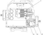
图1为本发明提供的寻北测角调节装置的主视剖的结构示意图;Fig. 1 is the structural schematic diagram of the main view section of the north-seeking angle-measuring adjustment device provided by the present invention;
图2为图1的右视且局部剖示意图;Fig. 2 is a right side view and a partial sectional view of Fig. 1;
图3为图1的俯视且局部剖示意图。FIG. 3 is a top view and partial cross-sectional view of FIG. 1 .
附图中:1、基座;2、方位蜗杆;3、方位蜗轮;4、阻尼轴承;5、角接触球轴承;6、方位编码器;7、方位转接轴;8、方位底座;9、承载平台;10、俯仰推动轴;12、俯仰蜗轮;13、俯仰蜗杆;14、方位摇轮;15、方位齿轮轴;16、方位齿轮;17、俯仰编码器;18、俯仰摇轮;19、光纤陀螺;20、石英挠性加表;21、摩擦材料垫。In the attached drawings: 1. base; 2. azimuth worm; 3. azimuth worm gear; 4. damping bearing; 5. angular contact ball bearing; 6. azimuth encoder; 7. azimuth transfer shaft; 8. azimuth base; 9 , carrying platform; 10, pitching drive shaft; 12, pitching worm gear; 13, pitching worm; 14, azimuth rocking wheel; 15, azimuth gear shaft; 16, azimuth gear; 17, pitching encoder; 18, pitching rocking wheel; 19 , Fiber optic gyroscope; 20, quartz flexible plus table; 21, friction material pad.
具体实施方式Detailed ways
以下将参考附图并结合实施例来详细说明本发明。需要说明的是,在不冲突的情况下,本发明中的实施例及实施例中的特征可以相互组合。为叙述方便,下文中如出现“上”、“下”、“左”、“右”字样,仅表示与附图本身的上、下、左、右方向一致,并不对结构起限定作用。The present invention will be described in detail below with reference to the accompanying drawings and examples. It should be noted that, in the case of no conflict, the embodiments of the present invention and the features in the embodiments can be combined with each other. For the convenience of description, if the words "up", "down", "left" and "right" appear in the following, it only means that the directions of up, down, left and right are consistent with the drawings themselves, and do not limit the structure.
如图1-图3所示,本实施例提供的一种寻北测角调节装置包括基座1、方位底座8、方位转动部件、俯仰转动部件、设于所述基座1顶部的承载平台9、及用于寻北的光纤陀螺19和石英挠性加表20。As shown in Figures 1-3, a north-seeking angle adjustment device provided in this embodiment includes a
所述承载平台9安装在基座顶部,为光学瞄准设备提供安装接口。所述方位转动部件安装在基座1内部下部,所述俯仰转动部件安装在基座1内部上部,所述承载平台9的一端与所述基座1铰接,另一端与俯仰转动部件的输出端连接;所述俯仰转动部件升降以使所述承载平台9进行俯仰角度调节。The
所述方位底座8设于所述基座1的底部,且将所述方位底座8进行固定式连接(如与其他支撑设备进行固连)。所述方位转动部件分别与所述方位底座8和所述基座1连接,通过所述方位转动部件以使所述基座1及其上的俯仰转动部件和承载平台9相对于方位底座8水平转动。The
在具体的实施例中,所述方位转动部件包括方位蜗轮3、方位蜗杆2、方位转接轴7、方位齿轮16、方位齿轮轴15、方位摇轮14和方位编码器6。所述方位蜗杆2通过轴承可转动的安装在所述基座1内,所述方位蜗杆2的末端螺纹固定连接所述方位齿轮16。所述方位齿轮16与所述方位齿轮轴15啮合,所述方位齿轮轴15通过轴承可转动的安装在所述基座1内(如图2所示),所述方位摇轮14与所述方位齿轮轴15固定,且所述方位摇轮14位于基座1的外侧。In a specific embodiment, the azimuth rotating parts include an
所述方位蜗轮3的外齿与所述方位蜗杆2啮合,所述方位蜗轮3的内圈通过阻尼轴承4与所述方位底座8装配。因阻尼轴承4为单向阻尼,因此,当方位蜗杆2驱动方位蜗轮3转动时,方位蜗轮3通过阻尼轴承4的阻尼作用下,与方位底座8形成运动的限定,由此,通过方位摇轮14驱动方位蜗杆2,使方位蜗杆2连同基座1及安装在基座1上的所有元器件一同转动(该转动为水平转动,转动轴为垂直于方位底座8的中心轴线)。所述方位蜗轮3的底部与方位底座8之间填充有摩擦材料垫21,以进一步增大方位蜗轮3和方位底座8之间的连接配合力。所述摩擦材料垫21可选用工程塑料,对方位蜗轮3和方位底座8实现紧配合。The outer teeth of the
所述方位转接轴7通过角接触球轴承5套装于所述方位底座8上,且所述方位转接轴7的上端与基座1固定。当基座1转动时,带动方位转接轴7一同转动。The azimuth adapter shaft 7 is sleeved on the
所述方位编码器6的定子端固定在方位转接轴7的内部,转子端通过连接轴和螺钉与方位底座8固连。连接轴的一端与方位底座8螺纹固定,另一端穿过方位编码器6再通过所述螺钉固定。The stator end of the
当转动方位摇轮14时,方位底座8与基座1之会间发生相对转动,从而实现方位角度精确调节;当手动转动基座1时,由于蜗轮蜗杆的自锁特性,方位蜗轮3与方位底座8之间发生相对转动,从而实现方位角度快速调节。When the
所述俯仰转动部件包括俯仰蜗杆13、俯仰蜗轮12、俯仰推动轴10、俯仰摇轮18和俯仰编码器17。所述俯仰推动轴10的上端与承载平台9连接,并通过承载平台9限制俯仰推动轴10的旋转自由度。所述俯仰推动轴10的下端与俯仰蜗轮12螺纹连接。所述俯仰蜗轮12与所述俯仰蜗杆13啮合,所述俯仰蜗轮12通过角接触球轴承5可转动的安装在所述基座1内。所述俯仰蜗杆13的末端与俯仰摇轮18固定连接,所述俯仰摇轮18位于基座1的外侧。所述俯仰编码器17的定子端与基座1固定,转子端与承载平台9固定。当转动俯仰摇轮18时,俯仰推动轴10发生上下运动,从而带动承载平台9实现俯仰角度精确调节。通过俯仰摇轮18实现装置的俯仰精调。The pitch rotating parts include a
陀螺加表部件:如图3所示,所述光纤陀螺19和石英挠性加表20设于所述基座1内。所述光纤陀螺19为两轴光纤陀螺,两轴光纤陀螺相互垂直安装在基座1相邻侧面,为装置提供高精度的方位基准。石英挠性加表20为两轴石英挠性加表,其集成安装在基座1内部,并与光纤陀螺19安装方向相对应,为装置提供高精度水平姿态基准。所述光纤陀螺19和石英挠性加表20配合相应的数据处理电路,实现了装置的寻北功能。Gyro meter adding component: as shown in FIG. 3 , the
本发明还提供一种采用上述寻北测角调节装置进行寻北测角的方法,包括如下步骤:The present invention also provides a method for north-seeking and angle-measuring using the above-mentioned north-seeking angle-measuring adjustment device, which includes the following steps:
1)先在静止状态通过光纤陀螺19和石英挠性加表20进行寻北;从而获得高精度的方位基准和水平姿态基准;1) North-seeking is first carried out in a static state through the
2)再转动基座1,使所述基座1带动承载平台9上搭载的光学瞄准设备转动,以实现方位粗调;2) Rotate the
3)再分别或同时调节方位转动部件和俯仰转动部件,带动承载平台9上搭载的光学瞄准设备转动;以实现方位精调;3) Adjust the azimuth rotating part and the pitching rotating part separately or simultaneously to drive the optical aiming device mounted on the carrying
4)承载平台9带动光学瞄准设备转动,实现目标跟踪测角;4) The carrying
上述步骤2)和3)无先后顺序。The above steps 2) and 3) are in no order.
以上所述仅为本发明的实施例,并非因此限制本发明的专利范围,凡是利用本发明说明书及附图内容所作的等效结构或等效流程变换,或直接或间接运用在其它相关的技术领域,均同理包括在本发明的专利保护范围内。The above is only an embodiment of the present invention, and does not limit the patent scope of the present invention. Any equivalent structure or equivalent process conversion made by using the description of the present invention and the contents of the accompanying drawings, or directly or indirectly used in other related technologies fields, all of which are equally included in the scope of patent protection of the present invention.
Claims (10)
Priority Applications (1)
| Application Number | Priority Date | Filing Date | Title |
|---|---|---|---|
| CN202210921695.1ACN115290083A (en) | 2022-08-02 | 2022-08-02 | North-finding angle-measuring adjusting device and method thereof |
Applications Claiming Priority (1)
| Application Number | Priority Date | Filing Date | Title |
|---|---|---|---|
| CN202210921695.1ACN115290083A (en) | 2022-08-02 | 2022-08-02 | North-finding angle-measuring adjusting device and method thereof |
Publications (1)
| Publication Number | Publication Date |
|---|---|
| CN115290083Atrue CN115290083A (en) | 2022-11-04 |
Family
ID=83826661
Family Applications (1)
| Application Number | Title | Priority Date | Filing Date |
|---|---|---|---|
| CN202210921695.1APendingCN115290083A (en) | 2022-08-02 | 2022-08-02 | North-finding angle-measuring adjusting device and method thereof |
Country Status (1)
| Country | Link |
|---|---|
| CN (1) | CN115290083A (en) |
Citations (11)
| Publication number | Priority date | Publication date | Assignee | Title |
|---|---|---|---|---|
| JPH0771962A (en)* | 1993-09-06 | 1995-03-17 | Tokimec Inc | Gyrocompass |
| CN101475018A (en)* | 2008-10-22 | 2009-07-08 | 国营红峰机械厂 | Two dimensional space running orbit tester based on double-shaft optical fiber gyroscope |
| CN203414084U (en)* | 2013-07-03 | 2014-01-29 | 九江精达检测技术有限公司 | High-precision north seeker device |
| CN105134171A (en)* | 2015-07-29 | 2015-12-09 | 北京航空航天大学 | Realization method for dual-spindle optic-fiber gyro continuous inclination measuring system |
| CN205778825U (en)* | 2016-06-07 | 2016-12-07 | 北京科技大学 | A kind of Inertial Measurement Unit |
| RU2610389C1 (en)* | 2015-11-16 | 2017-02-09 | Открытое акционерное общество "Специальное конструкторское бюро приборостроения и автоматики" | Gyro device |
| CN108444474A (en)* | 2018-05-03 | 2018-08-24 | 湖北三江航天红峰控制有限公司 | One kind minimizing high-precision optical fiber inertial positioning orienting device based on spatial reuse |
| CN111490819A (en)* | 2020-03-13 | 2020-08-04 | 威海市赢海通信技术有限公司 | Shipborne laser communication beam tracking control method based on fiber-optic gyroscope |
| CN113483727A (en)* | 2021-07-22 | 2021-10-08 | 江苏无线电厂有限公司 | Autonomous miniaturized directional equipment and north-seeking method |
| CN215340336U (en)* | 2021-04-23 | 2021-12-28 | 常州第二电子仪器有限公司 | Angle measuring platform with automatic north-seeking function |
| CN114322970A (en)* | 2021-11-30 | 2022-04-12 | 湖南航天机电设备与特种材料研究所 | Double-gyroscope north-seeking method, system and storage medium |
- 2022
- 2022-08-02CNCN202210921695.1Apatent/CN115290083A/enactivePending
Patent Citations (11)
| Publication number | Priority date | Publication date | Assignee | Title |
|---|---|---|---|---|
| JPH0771962A (en)* | 1993-09-06 | 1995-03-17 | Tokimec Inc | Gyrocompass |
| CN101475018A (en)* | 2008-10-22 | 2009-07-08 | 国营红峰机械厂 | Two dimensional space running orbit tester based on double-shaft optical fiber gyroscope |
| CN203414084U (en)* | 2013-07-03 | 2014-01-29 | 九江精达检测技术有限公司 | High-precision north seeker device |
| CN105134171A (en)* | 2015-07-29 | 2015-12-09 | 北京航空航天大学 | Realization method for dual-spindle optic-fiber gyro continuous inclination measuring system |
| RU2610389C1 (en)* | 2015-11-16 | 2017-02-09 | Открытое акционерное общество "Специальное конструкторское бюро приборостроения и автоматики" | Gyro device |
| CN205778825U (en)* | 2016-06-07 | 2016-12-07 | 北京科技大学 | A kind of Inertial Measurement Unit |
| CN108444474A (en)* | 2018-05-03 | 2018-08-24 | 湖北三江航天红峰控制有限公司 | One kind minimizing high-precision optical fiber inertial positioning orienting device based on spatial reuse |
| CN111490819A (en)* | 2020-03-13 | 2020-08-04 | 威海市赢海通信技术有限公司 | Shipborne laser communication beam tracking control method based on fiber-optic gyroscope |
| CN215340336U (en)* | 2021-04-23 | 2021-12-28 | 常州第二电子仪器有限公司 | Angle measuring platform with automatic north-seeking function |
| CN113483727A (en)* | 2021-07-22 | 2021-10-08 | 江苏无线电厂有限公司 | Autonomous miniaturized directional equipment and north-seeking method |
| CN114322970A (en)* | 2021-11-30 | 2022-04-12 | 湖南航天机电设备与特种材料研究所 | Double-gyroscope north-seeking method, system and storage medium |
Non-Patent Citations (2)
| Title |
|---|
| 秦粕云: "基于双轴光纤陀螺的井眼轨迹连续测斜仪研究", 中国优秀硕士学位论文全文数据库, 15 June 2018 (2018-06-15)* |
| 黄振: "石英挠性加速度计在角度检测中的应用", 导航与控制, 30 June 2016 (2016-06-30)* |
Similar Documents
| Publication | Publication Date | Title |
|---|---|---|
| CN103335640B (en) | A kind of automatic leveling and gyrocompassing see collimation device | |
| CN101776445B (en) | Magnetically suspended gyroscope total station | |
| CN100529662C (en) | Single axis fiber gyro north seeker | |
| CN110285816B (en) | High-precision attitude measurement system and method for small satellite on-satellite equipment | |
| CN106351643B (en) | Digital display triaxial inclinometer calibration stand | |
| CN102384730B (en) | A laser small-angle measuring device and a rotary shaft system | |
| CN106121630B (en) | A kind of single-axis servo continuous inclinometer Inertial Measurement Unit | |
| CN109752769A (en) | A parameter calibration method of a gravimeter stable platform measuring device | |
| CN201600134U (en) | A New Magnetic Suspension Gyro Total Station | |
| CN201181213Y (en) | Self-north seeking navigation device of uniaxial gyroscope | |
| CN114838721B (en) | A fiber optic gyro orientation instrument | |
| CN104655123B (en) | A kind of method that utilization optical fibre gyro determines rotational-angular velocity of the earth | |
| CN115290083A (en) | North-finding angle-measuring adjusting device and method thereof | |
| CN108036756B (en) | Method for detecting perpendicularity of adjacent axes of biaxial rotation inertia measurement device by using accelerometer | |
| CN109357689B (en) | Triaxial fiber gyroscope scale factor orthogonal modeling compensation method | |
| CN103744438A (en) | Spherical stable tracking platform | |
| CN118131359A (en) | High-precision establishment method for measurement reference of unmanned platform type gravity meter | |
| CN111397635A (en) | Rotation modulation method for MEMS inertial navigation system | |
| CN201477109U (en) | A laser gyro dynamic locking area measurement device | |
| CN116009185A (en) | Self-adaptive adjusting device for providing collimation reference | |
| CN104655095B (en) | A kind of method that utilization optical fibre gyro determines geographic latitude | |
| CN102023639A (en) | Controllable pendulum system based biaxial horizontal stabilized platform and control method thereof | |
| CN102661738A (en) | Meridian orientating device for aiming inertial system | |
| CN112362078B (en) | Method for measuring sensitive error of photoelectric turntable double-shaft fiber-optic gyroscope shafting | |
| RU2650425C1 (en) | Gyro-compass with visual channel |
Legal Events
| Date | Code | Title | Description |
|---|---|---|---|
| PB01 | Publication | ||
| PB01 | Publication | ||
| SE01 | Entry into force of request for substantive examination | ||
| SE01 | Entry into force of request for substantive examination |