CN115288738A - Simulation test system and method for decompression cut-off grouting in seepage cracks under high osmotic pressure - Google Patents
Simulation test system and method for decompression cut-off grouting in seepage cracks under high osmotic pressureDownload PDFInfo
- Publication number
- CN115288738A CN115288738ACN202210914888.4ACN202210914888ACN115288738ACN 115288738 ACN115288738 ACN 115288738ACN 202210914888 ACN202210914888 ACN 202210914888ACN 115288738 ACN115288738 ACN 115288738A
- Authority
- CN
- China
- Prior art keywords
- grouting
- chamber
- water
- osmotic pressure
- under high
- Prior art date
- Legal status (The legal status is an assumption and is not a legal conclusion. Google has not performed a legal analysis and makes no representation as to the accuracy of the status listed.)
- Pending
Links
- 230000003204osmotic effectEffects0.000titleclaimsabstractdescription36
- 230000006837decompressionEffects0.000titleclaimsabstractdescription35
- 238000004088simulationMethods0.000titleclaimsabstractdescription32
- 238000000034methodMethods0.000titleabstractdescription25
- XLYOFNOQVPJJNP-UHFFFAOYSA-NwaterSubstancesOXLYOFNOQVPJJNP-UHFFFAOYSA-N0.000claimsabstractdescription132
- 239000000463materialSubstances0.000claimsabstractdescription78
- BPQQTUXANYXVAA-UHFFFAOYSA-NOrthosilicateChemical compound[O-][Si]([O-])([O-])[O-]BPQQTUXANYXVAA-UHFFFAOYSA-N0.000claimsabstractdescription51
- 230000000903blocking effectEffects0.000claimsabstractdescription35
- 238000002347injectionMethods0.000claimsabstractdescription25
- 239000007924injectionSubstances0.000claimsabstractdescription25
- 239000011440groutSubstances0.000claimsdescription35
- 238000001514detection methodMethods0.000claimsdescription16
- 239000002002slurrySubstances0.000claimsdescription16
- 239000007788liquidSubstances0.000claimsdescription10
- 238000010998test methodMethods0.000claimsdescription9
- 230000003068static effectEffects0.000claimsdescription6
- 239000003566sealing materialSubstances0.000claimsdescription2
- 230000000694effectsEffects0.000abstractdescription12
- 238000007789sealingMethods0.000abstractdescription9
- 238000009412basement excavationMethods0.000abstractdescription6
- 230000015572biosynthetic processEffects0.000abstractdescription6
- 230000004048modificationEffects0.000abstractdescription6
- 238000012986modificationMethods0.000abstractdescription6
- 238000012954risk controlMethods0.000abstractdescription6
- 230000008569processEffects0.000description19
- 238000005187foamingMethods0.000description12
- 230000002787reinforcementEffects0.000description8
- 230000008859changeEffects0.000description6
- 238000005755formation reactionMethods0.000description5
- 239000011435rockSubstances0.000description5
- 239000011148porous materialSubstances0.000description4
- 230000004888barrier functionEffects0.000description3
- 238000010586diagramMethods0.000description2
- 239000012530fluidSubstances0.000description2
- 238000005065miningMethods0.000description2
- 239000000243solutionSubstances0.000description2
- 239000002699waste materialSubstances0.000description2
- RNFJDJUURJAICM-UHFFFAOYSA-N2,2,4,4,6,6-hexaphenoxy-1,3,5-triaza-2$l^{5},4$l^{5},6$l^{5}-triphosphacyclohexa-1,3,5-trieneChemical compoundN=1P(OC=2C=CC=CC=2)(OC=2C=CC=CC=2)=NP(OC=2C=CC=CC=2)(OC=2C=CC=CC=2)=NP=1(OC=1C=CC=CC=1)OC1=CC=CC=C1RNFJDJUURJAICM-UHFFFAOYSA-N0.000description1
- NIXOWILDQLNWCW-UHFFFAOYSA-Nacrylic acid groupChemical groupC(C=C)(=O)ONIXOWILDQLNWCW-UHFFFAOYSA-N0.000description1
- 230000009286beneficial effectEffects0.000description1
- 238000006243chemical reactionMethods0.000description1
- 238000004891communicationMethods0.000description1
- 230000007423decreaseEffects0.000description1
- 238000005516engineering processMethods0.000description1
- 239000000945fillerSubstances0.000description1
- 239000003063flame retardantSubstances0.000description1
- 239000006261foam materialSubstances0.000description1
- 239000011347resinSubstances0.000description1
- 229920005989resinPolymers0.000description1
- 150000003839saltsChemical class0.000description1
- RMAQACBXLXPBSY-UHFFFAOYSA-Nsilicic acidChemical compoundO[Si](O)(O)ORMAQACBXLXPBSY-UHFFFAOYSA-N0.000description1
- 235000012239silicon dioxideNutrition0.000description1
- 238000007711solidificationMethods0.000description1
- 230000008023solidificationEffects0.000description1
- 230000009466transformationEffects0.000description1
- 239000012780transparent materialSubstances0.000description1
Images


Classifications
- E—FIXED CONSTRUCTIONS
- E21—EARTH OR ROCK DRILLING; MINING
- E21D—SHAFTS; TUNNELS; GALLERIES; LARGE UNDERGROUND CHAMBERS
- E21D11/00—Lining tunnels, galleries or other underground cavities, e.g. large underground chambers; Linings therefor; Making such linings in situ, e.g. by assembling
- E21D11/04—Lining with building materials
- E21D11/10—Lining with building materials with concrete cast in situ; Shuttering also lost shutterings, e.g. made of blocks, of metal plates or other equipment adapted therefor
- E21D11/105—Transport or application of concrete specially adapted for the lining of tunnels or galleries ; Backfilling the space between main building element and the surrounding rock, e.g. with concrete
- E—FIXED CONSTRUCTIONS
- E21—EARTH OR ROCK DRILLING; MINING
- E21D—SHAFTS; TUNNELS; GALLERIES; LARGE UNDERGROUND CHAMBERS
- E21D11/00—Lining tunnels, galleries or other underground cavities, e.g. large underground chambers; Linings therefor; Making such linings in situ, e.g. by assembling
- E21D11/38—Waterproofing; Heat insulating; Soundproofing; Electric insulating
- E—FIXED CONSTRUCTIONS
- E21—EARTH OR ROCK DRILLING; MINING
- E21F—SAFETY DEVICES, TRANSPORT, FILLING-UP, RESCUE, VENTILATION, OR DRAINING IN OR OF MINES OR TUNNELS
- E21F17/00—Methods or devices for use in mines or tunnels, not covered elsewhere
- E—FIXED CONSTRUCTIONS
- E21—EARTH OR ROCK DRILLING; MINING
- E21F—SAFETY DEVICES, TRANSPORT, FILLING-UP, RESCUE, VENTILATION, OR DRAINING IN OR OF MINES OR TUNNELS
- E21F17/00—Methods or devices for use in mines or tunnels, not covered elsewhere
- E21F17/18—Special adaptations of signalling or alarm devices
Landscapes
- Engineering & Computer Science (AREA)
- Mining & Mineral Resources (AREA)
- Structural Engineering (AREA)
- Life Sciences & Earth Sciences (AREA)
- General Life Sciences & Earth Sciences (AREA)
- Geochemistry & Mineralogy (AREA)
- Geology (AREA)
- Architecture (AREA)
- Civil Engineering (AREA)
- Consolidation Of Soil By Introduction Of Solidifying Substances Into Soil (AREA)
Abstract
Translated fromChinese
Description
Translated fromChinese技术领域technical field
本发明涉及注浆封堵技术领域,特别是涉及一种高渗透压下渗水裂隙的减压截断注浆模拟试验系统及方法。The invention relates to the technical field of grouting plugging, in particular to a decompression cut-off grouting simulation test system and method for water seepage cracks under high osmotic pressure.
背景技术Background technique
在采矿以及开凿隧道的过程中发现,围岩裂隙发育,除了由碎裂岩体构成的主要渗水通道之外,还存在数量众多的微小渗水裂隙。裂隙之间相互导通,无法同时封堵,现场注浆始终处于动水注浆状态。这导致了一部分浆液在凝固之前就从渗水裂隙流失,注浆效果大打折扣,并且造成了严重的材料浪费。为解决上述问题,需要对动水环境下的注浆效果进行模拟试验,以找到最佳封堵方法,因此亟待研发一种能够真实模拟动水环境下注浆效果的试验装置。In the process of mining and excavating tunnels, it was found that cracks in the surrounding rock were well developed. In addition to the main water seepage channel formed by the broken rock mass, there were also a large number of tiny water seepage cracks. The cracks are connected to each other and cannot be blocked at the same time, and the on-site grouting is always in the state of dynamic water grouting. This caused a part of the grout to be lost from the seepage cracks before solidification, greatly reducing the grouting effect and causing serious waste of materials. In order to solve the above problems, it is necessary to carry out a simulation test on the grouting effect in a dynamic water environment to find the best plugging method. Therefore, it is urgent to develop a test device that can truly simulate the grouting effect in a dynamic water environment.
申请号为201920911868.5的专利申请,采用的技术方案是提供一种模拟不同填充物裂隙的动水注浆试验装置,在水头压力、注水流量、注浆压力等参数设定好的条件下进行注浆,在试验模型箱内铺设好特制的橡胶垫,相对应的小孔位置设置好注浆管以及压力测量装置,其外端连接好注水装置、注浆装置和废液收集装置,进行浆液配置,对该装置进行注水后,再进行注浆。但是该注浆试验装置气密性不佳,极大的影响了其采集的各项参数的准确性,更无法模拟高压环境下的注浆封堵效果,且其注浆管口固定设置,单次试验只能对注入一种浆液,无法同时对多种浆液的注浆效果进行模拟,因此也无法模拟复杂环境中需要进行多种浆料相互辅助注浆封堵的真实效果。The patent application with the application number 201920911868.5 adopts a technical solution to provide a dynamic water grouting test device for simulating the cracks of different fillers, and grouting is carried out under the conditions of water head pressure, water injection flow rate, and grouting pressure and other parameters. , Lay a special rubber pad in the test model box, install a grouting pipe and a pressure measuring device at the corresponding small hole position, and connect the water injection device, grouting device and waste liquid collection device at the outer end to configure the grout. After the device is filled with water, it is then grouted. However, the airtightness of the grouting test device is not good, which greatly affects the accuracy of the collected parameters, and it is impossible to simulate the plugging effect of grouting in a high-pressure environment, and the grouting nozzle is fixed. This test can only inject one kind of grout, and it is impossible to simulate the grouting effect of multiple grouts at the same time, so it is also impossible to simulate the real effect of mutual auxiliary grouting and plugging of multiple grouts in a complex environment.
发明内容Contents of the invention
为了克服深部地层的赋存特征和竖井开挖扰动所导致的突水工程风险,本发明提供一种高渗透压下渗水裂隙的减压截断注浆模拟试验系统及方法,从而真实模拟井筒深部开挖高渗透压环境下进行减压截断注浆的试验效果,提高注浆封堵率,为破碎富水区地层改性和突水风险控制提供了技术支撑。In order to overcome the occurrence characteristics of deep formations and the risk of water inrush engineering caused by shaft excavation disturbance, the present invention provides a decompression cut-off grouting simulation test system and method for water seepage cracks under high osmotic pressure, so as to truly simulate the deep wellbore opening The experimental results of decompression cut-off grouting under high osmotic pressure environment have improved the plugging rate of grouting, and provided technical support for stratum modification and water inrush risk control in broken water-rich areas.
为解决上述技术问题,本发明采用的技术方案是:提供一种高渗透压下渗水裂隙的减压截断注浆模拟试验系统,其包括:注浆腔室、分序注浆管件、多个压力检测部件,第一注浆材料盛放腔、第二注浆材料盛放腔以及注浆泵,其中,所述注浆腔室内填充满碎石,其首端设有注水口,靠近其末端的顶部设有溢流口,所述分序注浆管件的出浆管口设置在注浆腔室内,并能够伸入注浆腔室的各个位置;多个所述压力检测部件沿注浆腔室长度延伸方向均匀分布设置在注浆腔室上;所述第一注浆材料盛放腔、第二注浆材料盛放腔通过注浆泵与分序注浆管件连接,所述第一注浆材料盛放腔内盛放的材料为发泡型硅酸盐堵水材料,所述第二注浆材料盛放腔内盛放的材料为加固型硅酸盐封堵材料。In order to solve the above technical problems, the technical solution adopted by the present invention is to provide a simulation test system for decompression cut-off grouting of water seepage cracks under high osmotic pressure, which includes: grouting chamber, sequential grouting pipe fittings, multiple pressure Detection components, the first grouting material holding chamber, the second grouting material holding chamber and the grouting pump, wherein the grouting chamber is filled with crushed stones, its head end is provided with a water injection port, and the grouting chamber near its end The top is provided with an overflow port, and the grout outlet of the sequenced grouting pipe is set in the grouting chamber and can extend into various positions of the grouting chamber; The length extension direction is evenly distributed on the grouting chamber; the first grouting material holding chamber and the second grouting material holding chamber are connected to the sequential grouting pipe fittings through the grouting pump, and the first grouting material The material contained in the material containing cavity is a foamed silicate water blocking material, and the material contained in the second grouting material containing cavity is a reinforced silicate plugging material.
优选的,所述分序注浆管件包括一端分别自注浆腔室末端伸入注浆腔室内的长、短注浆管,所述长注浆管伸入注浆腔室内的长度大于短注浆管伸入注浆腔室内的长度,所述长注浆管伸入注浆腔室内的长度大于注浆腔室长度的一半。Preferably, the sequenced grouting pipes include long and short grouting pipes with one end extending into the grouting chamber from the end of the grouting chamber respectively, and the length of the long grouting pipe extending into the grouting chamber is longer than the length of the short grouting pipe. The length of the grouting pipe extending into the grouting chamber, the length of the long grouting pipe extending into the grouting chamber is greater than half of the length of the grouting chamber.
优选的,所述分序注浆管件包括一端自注浆腔室首端伸入注浆腔室内的第一注浆管,及一端自注浆腔室末端伸入注浆腔室内的第二注浆管。Preferably, the sequential grouting pipe includes a first grouting pipe whose end extends into the grouting chamber from the head end of the grouting chamber, and a second grouting pipe whose end extends into the grouting chamber from the end of the grouting chamber. pulp tube.
优选的,所述分序注浆管件为一自注浆腔室末端伸入注浆腔室内、并能够自由调节伸入注浆腔室内管体长度的注浆管。Preferably, the sequential grouting pipe is a grouting pipe that extends from the end of the grouting chamber into the grouting chamber and can freely adjust the length of the pipe body extending into the grouting chamber.
优选的,所述第二注浆材料盛放腔连接的注浆管件与注水口分设于注浆腔室的两端,且所述第二注浆材料盛放腔连接的注浆管件与溢流口同侧设置。Preferably, the grouting pipe fittings connected to the second grouting material storage chamber and the water injection port are respectively arranged at both ends of the grouting chamber, and the grouting pipe fittings connected to the second grouting material storage chamber are connected to the overflow Set on the same side as the mouth.
优选的,所述第一注浆材料盛放腔、第二注浆材料盛放腔分别与一活塞式气动双液注浆泵的第一输入口、第二输入口连接,所述活塞式气动双液注浆泵的第一输出口、第二输出口分别通过注浆管道与分序注浆管件连接。Preferably, the first grouting material storage chamber and the second grouting material storage chamber are respectively connected to the first input port and the second input port of a piston-type pneumatic double-liquid grouting pump, and the piston-type pneumatic The first output port and the second output port of the double liquid grouting pump are respectively connected with the sequential grouting pipe fittings through the grouting pipeline.
优选的,所述活塞式气动双液注浆泵与分序注浆管件之间的注浆管道内设有多个静态混合器,多个所述静态混合器沿注浆混合管道长度延伸方向依次串联设置。Preferably, a plurality of static mixers are arranged in the grouting pipeline between the piston-type pneumatic double-fluid grouting pump and the sequential grouting pipe fittings, and the plurality of static mixers are sequentially arranged along the length extension direction of the grouting mixing pipeline. Tandem settings.
优选的,所述注浆管道与分序注浆管件为可拆卸连接。Preferably, the grouting pipeline is detachably connected to the sequential grouting pipe fitting.
本发明还提供一种采用所述的一种高渗透压下渗水裂隙的减压截断注浆模拟试验系统的高渗透压下渗水裂隙的减压截断注浆模拟试验方法,其包括如下步骤:The present invention also provides a simulation test method for decompression and truncation grouting of water seepage cracks under high osmotic pressure using the above-mentioned simulation test system for decompression truncation grouting of water seepage cracks under high osmotic pressure, which includes the following steps:
S1、在所述注浆腔室内填充满碎石;S1, filling the grouting chamber with gravel;
S2、通过注水口不断向注浆腔室内注入水流;S2. Continuously inject water into the grouting chamber through the water injection port;
S3、通过分序注浆管件向注浆腔室前半段注入一定量发泡型硅酸盐堵水浆液,静止一段时间,观察注浆腔室顶部的溢流口,当注浆腔室顶部的溢流口不再溢出水流,不再注入发泡型硅酸盐堵水浆液,反之循环步骤S3;S3. Inject a certain amount of foamed silicate water blocking grout into the first half of the grouting chamber through the sequential grouting pipe fittings, stand still for a period of time, observe the overflow port on the top of the grouting chamber, when the top of the grouting chamber The overflow port no longer overflows the water flow, and no longer injects the foamed silicate water blocking slurry, and vice versa, cycle step S3;
S4、当注浆腔室顶部的溢流口不再溢出水流时,通过分层分序注浆管向注浆腔室的后半段注入加固型硅酸盐封堵浆液,观察注浆腔室顶部的溢流口,当注浆腔室顶部的溢流口有加固型硅酸盐封堵浆液溢出时,完成注浆。S4. When the overflow port at the top of the grouting chamber no longer overflows the water flow, inject reinforced silicate plugging grout into the second half of the grouting chamber through the layered and sequential grouting pipe, and observe the grouting chamber The overflow port at the top, when the overflow port at the top of the grouting chamber has reinforced silicate plugging grout overflowing, the grouting is completed.
优选的,在向注浆腔室内注入加固型硅酸盐封堵浆液时,实时观察注浆腔室末端的压力检测部件的数值,当注浆腔室末端的压力检测部件检测压力值达到预设峰值时,停止注浆。Preferably, when the reinforced silicate plugging slurry is injected into the grouting chamber, the value of the pressure detection component at the end of the grouting chamber is observed in real time, and when the pressure detected by the pressure detection component at the end of the grouting chamber reaches a preset value At peak, stop grouting.
本发明的有益效果是:The beneficial effects of the present invention are:
本发明通过设置注水口为模拟高压动水环境提供条件,并设置能够伸入注浆腔室的各个位置的分序注浆管件,用于将所述发泡型硅酸盐堵水材料注入注浆腔体中部形成密封阻断层,并将所述加固型硅酸盐封堵材料注入相对注水口另一侧的密封阻断空间中,以真实模拟高渗透压环境下进行减压截断注浆的试验效果;即先通过发泡型硅酸盐堵水材料对水路进行封堵,然后用加固型硅酸盐封堵材料对密封阻断空间内的缝隙进行填充注浆,直至浆液自注浆腔室顶部的溢流口溢出,通过压力检测部件记录得到其注浆过程中的全部压力变化参数,为破碎富水区地层改性和突水风险控制提供了技术支撑。The present invention provides conditions for simulating a high-pressure dynamic water environment by setting a water injection port, and sets sequential grouting pipe fittings that can extend into various positions of the grouting chamber to inject the foamed silicate water blocking material into the grouting chamber. A sealing blocking layer is formed in the middle of the slurry chamber, and the reinforced silicate plugging material is injected into the sealing blocking space on the other side of the opposite water injection port to truly simulate the decompression cut-off grouting in a high osmotic pressure environment The test effect; that is, the waterway is blocked by the foamed silicate water blocking material first, and then the gap in the sealed blocking space is filled and grouted with the reinforced silicate plugging material until the grout is self-grouting The overflow port on the top of the chamber overflows, and all the pressure change parameters during the grouting process are recorded by the pressure detection component, which provides technical support for the formation modification of the broken water-rich area and the risk control of water inrush.
本发明针对深部地层的赋存特征和竖井开挖扰动所导致的突水工程风险,通过高渗透压下渗水裂隙的减压截断注浆模拟试验装置真实模拟出在井筒深部开挖高渗透压环境下,采取先发泡后加固的次序进行注浆,实现减压截断注浆的试验效果,提高注浆封堵率。The present invention aims at the occurrence characteristics of deep formations and the risk of water inrush engineering caused by the disturbance of shaft excavation, and through the decompression and truncation grouting simulation test device of water seepage cracks under high osmotic pressure, the high osmotic pressure environment of deep excavation in the wellbore is truly simulated. Under this condition, the grouting is carried out in the order of first foaming and then reinforcement, so as to realize the test effect of decompression cut-off grouting and improve the plugging rate of grouting.
附图说明Description of drawings
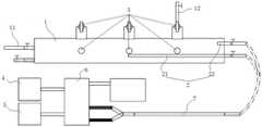
图1为本发明实施例1所述高渗透压下渗水裂隙的减压截断注浆模拟试验系统的结构原理示意图。Fig. 1 is a schematic diagram of the structure and principle of the decompression cut-off grouting simulation test system for water seepage fractures under high osmotic pressure according to Example 1 of the present invention.
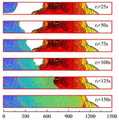
图2为采用本发明实施例2所述高渗透压下渗水裂隙的减压截断注浆模拟试验方法进行注浆过程中发泡注浆浆液流动规律图。Fig. 2 is a flow chart of the foaming grouting slurry during the grouting process using the decompression cut-off grouting simulation test method for water seepage cracks under high osmotic pressure described in Example 2 of the present invention.
图3为采用本发明实施例2所述高渗透压下渗水裂隙的减压截断注浆模拟试验方法进行注浆过程中加固注浆浆液流动规律图。Fig. 3 is a diagram showing the flow law of the reinforcement grout during the grouting process using the decompression cut-off grouting simulation test method for water seepage cracks under high osmotic pressure described in Example 2 of the present invention.
图4为采用本发明实施例2所述高渗透压下渗水裂隙的减压截断注浆模拟试验方法进行注浆过程中注浆腔室内部压力变化图。Fig. 4 is a graph showing pressure changes inside the grouting chamber during the grouting process using the decompression cut-off grouting simulation test method for water seepage cracks under high osmotic pressure described in Example 2 of the present invention.
附图中各部件的标记如下:The marks of each part in the accompanying drawings are as follows:
1、注浆腔室;11、注水口;12、溢流口;2、分序注浆管件;21、长注浆管;22、短注浆管;3、压力检测部件;4、第一注浆材料盛放腔;5、第二注浆材料盛放腔;6、注浆泵;7、注浆管道。1. Grouting chamber; 11. Water injection port; 12. Overflow port; 2. Sequential grouting pipe fittings; 21. Long grouting pipe; 22. Short grouting pipe; 3. Pressure detection parts; 4. First Grouting material containing cavity; 5. Second grouting material containing cavity; 6. Grouting pump; 7. Grouting pipeline.
具体实施方式Detailed ways
下面结合附图对本发明的较佳实施例进行详细阐述,以使本发明的优点和特征能更易于被本领域技术人员理解,从而对本发明的保护范围做出更为清楚明确的界定。The preferred embodiments of the present invention will be described in detail below in conjunction with the accompanying drawings, so that the advantages and features of the present invention can be more easily understood by those skilled in the art, so as to define the protection scope of the present invention more clearly.
实施例1Example 1
本发明实施例1提供一种高渗透压下渗水裂隙的减压截断注浆模拟试验系统,其用于真实模拟在动水环境下多种浆液配合封堵的试验效果,为采矿以及开凿隧道或者矿井的过程中产生的微小渗水裂隙的封堵提供参考指标和数据,为破碎富水区地层改性和突水风险控制提供了技术支撑。
如图1所示,所述高渗透压下渗水裂隙的减压截断注浆模拟试验系统包括:注浆腔室1、分序注浆管件2、多个压力检测部件3,第一注浆材料盛放腔4、第二注浆材料盛放腔5以及注浆泵6。其中,所述注浆腔室1内填充满碎石,其首端设有注水口11,为试验提供高压动水模拟环境;靠近其末端的顶部设有溢流口12,多余的水流和浆液能够自溢流口12溢出;所述分序注浆管件2的出浆口设置在注浆腔室1内,并能够伸入注浆腔室1的各个位置,从而可以实现在注浆室内的不同位置进行注浆;多个所述压力检测部件3沿注浆腔室1长度延伸方向均匀分布设置在注浆腔室1上,实时监测注浆室内各部位收到的压强;所述第一注浆材料盛放腔4、第二注浆材料盛放腔5通过注浆泵与分序注浆管件 2连接,所述第一注浆材料盛放腔4内盛放的材料为发泡型硅酸盐堵水材料,优选采用宏禹牌阻燃型硅酸盐发泡材料;所述第二注浆材料盛放腔5内盛放的材料为加固型硅酸盐封堵材料,优选采用宏禹牌硅酸盐树脂。在高压动水环境下,通过所述分序注浆管件2将所述发泡型硅酸盐堵水材料注入注浆腔体中部形成密封阻断层,并将所述加固型硅酸盐封堵材料注入相对注水口11另一侧的密封阻断空间中,从而真实模拟高渗透压环境下进行减压截断注浆的试验效果。As shown in Figure 1, the decompression truncation grouting simulation test system for water seepage cracks under high osmotic pressure includes: a
所述注浆腔室1采用整体透明材质制成,能够方便观察注浆过程中浆液流动现象。优选的,所述注浆腔室1为采用亚克力一体成型的圆柱形腔体。The
如图1所示,所述分序注浆管件2包括一端分别自注浆腔室1末端伸入注浆腔室1内的长、短注浆管22,所述长注浆管21伸入注浆腔室1内的长度大于短注浆管22伸入注浆腔室1内的长度,所述长注浆管21伸入注浆腔室1内的长度大于注浆腔室1长度的一半,所述长注浆管21用于向注浆腔室1内注入发泡型硅酸盐堵水材料,所述短注浆管22用于向注浆腔室1内注入加固型硅酸盐封堵材料。As shown in Figure 1, the sequenced grouting pipe fitting 2 includes long and
当所述长注浆管21将发泡型硅酸盐堵水材料注入注浆腔体中部形成密封阻断层,阻隔注水口11的水流继续流入注浆腔室1的末端;所述短注浆管22将所述加固型硅酸盐封堵材料注入相对注水口11另一侧的密封阻断空间中,对该密封阻断空间内的所有孔隙进行填充密封,直至浆液自注浆腔室1顶部的溢流口12溢出。When the
所述分序注浆管件2还可以采用其他多种形式结构,例如:所述分序注浆管件2包括一端自注浆腔室1首端伸入注浆腔室1内的第一注浆管,及一端自注浆腔室1末端伸入注浆腔室1内的第二注浆管,具体的,所述第一注浆管伸入注浆腔室1的中部设置;所述第一注浆管用于向注浆腔室1内注入发泡型硅酸盐堵水材料,所述第二注浆管用于向注浆腔室1内注入加固型硅酸盐封堵材料。The sequential grouting pipe fitting 2 can also adopt other various forms of structures, for example: the sequential grouting pipe fitting 2 includes a first grouting chamber with one end extending from the head end of the
所述分序注浆管件2还可以为一自注浆腔室1末端伸入注浆腔室1内、并能够自由调节伸入注浆腔室1内管体长度的注浆管,所述注浆管管体与所述注浆腔室1的腔壁滑动气密性连接,保证了注浆腔室1的气密性。当分序注浆管件2的出浆口12调节至注浆腔室1中部时,其通过注浆管道7与第一注浆材料盛放腔4连接,向注浆腔室1内注入发泡型硅酸盐堵水材料;当分序注浆管件2 的出浆口12调节至注浆腔室1末端时,其通过注浆管道7与第二注浆材料盛放腔5连接,向注浆腔室1内注入加固型硅酸盐封堵材料。The sequential grouting pipe fitting 2 can also be a grouting pipe that extends into the
不管分序注浆管件2的结构形式如何变化,所述第二注浆材料盛放腔5连接的注浆管件始终与注水口11分设于注浆腔室1的两端,且所述第二注浆材料盛放腔5连接的注浆管件与溢流口12同侧设置。No matter how the structural form of the
具体的,所述第一注浆材料盛放腔4、第二注浆材料盛放腔5通过一活塞式气动双液注浆泵6与分序注浆管件2连接,如图1所示,所述第一注浆材料盛放腔4、第二注浆材料盛放腔5分别与一活塞式气动双液注浆泵6的第一输入口、第二输入口连接,所述活塞式气动双液注浆泵6的第一输出口、第二输出口通过一三通管与注浆管道7的一端连接,所述注浆管道7的另一端与分序注浆管件2连接。进一步的,所述注浆管道7内设有多个静态混合器,多个所述静态混合器沿注浆混合管道长度延伸方向依次串联设置,用于对经过注浆管道7的浆液进行充分混合。Specifically, the first grouting material storage chamber 4 and the second grouting
由于在注浆的过程中,所述注浆管道7需要对多种不同的浆液进行注浆,且每次注浆之后都需要及时对注浆管道7进行清洗,因此所述注浆管道7与分序注浆管件2之间为可拆卸连接。Because in the grouting process, the grouting pipeline 7 needs to grout a variety of different grouts, and the grouting pipeline 7 needs to be cleaned in time after each grouting, so the grouting pipeline 7 and The sequential
本发明实施例所述一种高渗透压下渗水裂隙的减压截断注浆模拟试验系统,其通过设置注水口11为模拟高压动水环境提供条件,并设置能够伸入注浆腔室1的各个位置的分序注浆管件2,用于将所述发泡型硅酸盐堵水材料注入注浆腔体中部形成密封阻断层,并将所述加固型硅酸盐封堵材料注入相对注水口 11另一侧的密封阻断空间中,以真实模拟高渗透压环境下进行减压截断注浆的试验效果;即先通过发泡型硅酸盐堵水材料对水路进行封堵,然后用加固型硅酸盐封堵材料对密封阻断空间内的缝隙进行填充注浆,直至浆液自注浆腔室1 顶部的溢流口12溢出,通过压力检测部件3记录得到其注浆过程中的全部压力变化参数,为破碎富水区地层改性和突水风险控制提供了技术支撑。The embodiment of the present invention describes a decompression cut-off grouting simulation test system for water seepage fissures under high osmotic pressure, which provides conditions for simulating a high-pressure dynamic water environment by setting a
实施例2Example 2
本发明实施例2提供一种采用实施例1中一种高渗透压下渗水裂隙的减压截断注浆模拟试验系统的高渗透压下渗水裂隙的减压截断注浆模拟试验方法,其包括如下步骤:
S1、在所述注浆腔室1内填充满碎石;S1, filling the
S2、通过注水口11不断向注浆腔室1内注入水流;S2. Continuously inject water into the
S3、通过分序注浆管件2向注浆腔室1前半段注入一定量发泡型硅酸盐堵水浆液,静止一段时间,观察注浆腔室1顶部的溢流口12,当注浆腔室1顶部的溢流口12不再溢出水流,不再注入发泡型硅酸盐堵水浆液,反之循环步骤S3;S3. Inject a certain amount of foamed silicate water blocking slurry into the first half of the
S4、当注浆腔室1顶部的溢流口12不再溢出水流时,通过分层分序注浆管向注浆腔室1的后半段注入加固型硅酸盐封堵浆液,观察注浆腔室1顶部的溢流口12,当注浆腔室1顶部的溢流口12有加固型硅酸盐封堵浆液溢出时,完成注浆。S4. When the
其中,在向注浆腔室1前半段注入一定量发泡型硅酸盐堵水浆液之前,所述注浆腔体内必须完全充满水,水流会从其顶部的溢流口12不断溢出,且观察各部位压力检测部件3,在注浆腔体内压力平衡的状态下才能开始注浆。Wherein, before a certain amount of foamed silicate water blocking grout is injected into the first half of the
需要说明的是,每一次注浆完成之后,需要及时清洗注浆管道7。It should be noted that after each grouting is completed, the grouting pipeline 7 needs to be cleaned in time.
在向注浆腔室1内注入加固型硅酸盐封堵浆液时,实时观察注浆腔室1末端的压力检测部件3的数值,当注浆腔室1末端的压力检测部件3检测压力值达到预设峰值时,停止注浆。优选的,所述预设峰值为1MPa。When injecting reinforced silicate plugging slurry into the
需要注意的是,在注浆的过程中,如果注浆压力开始突然升高时,表明部分浆液已经开始硬化,必须马上停止注浆。It should be noted that during the grouting process, if the grouting pressure starts to rise suddenly, it indicates that part of the grout has begun to harden, and the grouting must be stopped immediately.
为进一步说明,本发明具体采用尺寸为
S1、在
S2、将注水口11连接0.2MPa稳定水源不断向注浆腔室1内注入水流;S2. Connect the
S3、通过分序注浆管件2向注浆腔室1前半段注入2L发泡型硅酸盐堵水浆液,静止一段时间,观察发泡型硅酸盐堵水浆液发泡情况以及注浆腔室1顶部的溢流口12,当注浆腔室1顶部的溢流口12不再溢出水流,不再注入发泡型硅酸盐堵水浆液,反之循环步骤S3;S3. Inject 2L of foamed silicate water plugging slurry into the first half of the
S4、当注浆腔室1顶部的溢流口12不再溢出水流时,通过分层分序注浆管向注浆腔室1的后半段注入加固型硅酸盐封堵浆液,观察注浆腔室1顶部的溢流口12,当注浆腔室1顶部的溢流口12有加固型硅酸盐封堵浆液溢出时,完成注浆。S4. When the
在上述注浆过程中,每5s记录一次浆液流动的外轮廓,绘制了加固注浆过程浆液流动规律图,见图2。记录不同试验流程中液体压力的变化,压力表读数间隔为1s,并计算压力平均值。压水测试、注浆过程中注浆腔室1内部压力变化见图3。During the above grouting process, the outer contour of the grout flow was recorded every 5 s, and the flow pattern of the grout during the reinforcement grouting process was drawn, as shown in Figure 2. Record the change of liquid pressure in different test procedures, the pressure gauge reading interval is 1s, and calculate the average pressure. See Figure 3 for pressure changes inside the
图4(a)是在注浆之前进行压水测试阶段注浆腔室1内的压力变化,曲线可以分为三个阶段,第一个阶段是注水过程中,为0至19s,此阶段压力逐步升高,内部水压达到1MPa。第二阶段是注水停止后,为19s至51s,此阶段水压逐渐降低。第三阶段是排水泄压阶段,为51s至55s,此阶段注浆腔室1中的水压迅速下降。在压水测试的各个阶段,不同位置的压力基本保持相同,说明砾石充填的注浆腔室1内部液体联通性良好,并且注浆过程中腔室具有良好的密封性。Figure 4(a) is the pressure change in the
图4(b)是发泡注浆阶段注浆腔室1内的压力变化,t1表示发泡注浆开始的时间,注浆过程初期t1+0至t1+35s注浆腔室1内压力有小范围波动,之后曲线基本持平,基本与外接水压保持一致。发泡注浆阶段可以分为注浆过程和发泡过程,根据发泡注浆阶段的注浆停止规则,在t1+120s时已经完成注浆,t1+120s 至t1+240s为发泡阶段,反应中的发泡浆液体积膨胀,此过程压力表读数保持不变。t1+240s之后可以发现出浆管停止出水,注水口11另一侧的密封阻断空间中的流动水已经变为静止水,表明发泡型硅酸盐堵水材料已经在注浆腔体内形成密封阻断层,将水流封堵住。Figure 4(b) shows the pressure change in the
图4(c)是加固注浆阶段注浆腔室1内的压力变化,位于1125mm处的压力曲线明显与位于375mm和750mm处的压力曲线变化趋势不同。t2为加固注浆开始的时间,位于375mm和750mm处的压力可以分为4个阶段,第一阶段为t2+0至t2+13s,表现为注浆压力逐步升高至0.5MPa;第二阶段为t2+13至 t2+138s,随着注浆继续,浆液压力维持在0.45MPa上下波动,并逐渐平稳;第三阶段为t2+138s至t2+154s,表现为压力快速上升,原因一是加固浆液已经完全充填了左侧砾石中孔隙,开始充填发泡注浆区域;二是随着注浆的进行,最早注入注浆腔室1的加固浆液已经开始反应,逐渐硬化。第四阶段为t2+155之后,根据加固注浆阶段的注浆停止规则,浆液压力在到达1MPa后停止注浆,之后压力迅速跌至0。原因是停止注浆后浆液存在回流的现象,导致注浆腔室1内部压力突降。对于位置为1125mm处,在t2+0至t2+165s之间,压力始终维持在0.2MPa上下,因为在发泡注浆阶段已经封堵了流动水,注浆腔室1中部的孔隙被封堵,左侧与右侧的孔隙不再联通,因此注浆压力无法传递到右侧。Figure 4(c) shows the pressure change in the
注浆完成之后,对注浆体进行脱模钻芯取样,并对样体的孔隙率进行检测:After the grouting is completed, the grouting body is demolded and cored to sample, and the porosity of the sample body is tested:
注浆充填率η为注浆前、后的岩石孔隙率差值与注浆前岩石孔隙率的比值。此处孔隙率通过测量密度,反推孔隙率。试验前用的碎石堆积密度为ρ0=1500kg/m3,岩石近似密度为ρ=2700kg/m3,注浆前的孔隙率可由公式 P=1-ρ0/ρ表示,注浆前的孔隙率为0.44。The grouting filling rate η is the ratio of the rock porosity difference before and after grouting to the rock porosity before grouting. Here, the porosity is calculated by measuring the density, and the porosity is deduced inversely. The bulk density of the gravel used before the test is ρ0=1500kg/m3, the approximate density of the rock is ρ=2700kg/m3, the porosity before grouting can be expressed by the formula P=1-ρ0/ρ, the porosity before grouting is 0.44 .
注浆后经测量,密实区域的密度可以达到为2.017g/cm3,注浆材料的自身密度为1.23~1.375g/cm3,由此可以计算,充填后的孔隙率为0.02。可计算得到注浆充填率为95.5%。After grouting, it is measured that the density of the dense area can reach 2.017g/cm3, and the density of the grouting material itself is 1.23-1.375g/cm3, so it can be calculated that the porosity after filling is 0.02. It can be calculated that the grouting filling rate is 95.5%.
本发明实施例2所述一种高渗透压下渗水裂隙的减压截断注浆模拟试验方法,其针对深部地层的赋存特征和竖井开挖扰动所导致的突水工程风险,通过高渗透压下渗水裂隙的减压截断注浆模拟试验装置真实模拟出在井筒深部开挖高渗透压环境下,采取先发泡后加固的次序进行注浆,实现减压截断注浆的试验效果,提高注浆封堵率,为破碎富水区地层改性和突水风险控制提供了技术支撑。A simulation test method for decompression cut-off grouting of water seepage cracks under high osmotic pressure described in Example 2 of the present invention, which aims at the occurrence characteristics of deep strata and the risk of water inrush engineering caused by shaft excavation disturbance, through high osmotic pressure The decompression cut-off grouting simulation test device for the seepage water fracture truly simulates the high osmotic pressure environment of the deep excavation of the wellbore. The slurry plugging rate provides technical support for formation modification and water inrush risk control in broken water-rich areas.
以上所述仅为本发明的实施例,并非因此限制本发明的专利范围,凡是利用本发明说明书及附图内容所作的等效结构或等效流程变换,或直接或间接运用在其他相关的技术领域,均同理包括在本发明的专利保护范围内。The above is only an embodiment of the present invention, and does not limit the patent scope of the present invention. Any equivalent structure or equivalent process transformation made by using the description of the present invention and the contents of the accompanying drawings, or directly or indirectly used in other related technologies fields, all of which are equally included in the scope of patent protection of the present invention.
Claims (10)
Translated fromChinesePriority Applications (1)
| Application Number | Priority Date | Filing Date | Title |
|---|---|---|---|
| CN202210914888.4ACN115288738A (en) | 2022-08-01 | 2022-08-01 | Simulation test system and method for decompression cut-off grouting in seepage cracks under high osmotic pressure |
Applications Claiming Priority (1)
| Application Number | Priority Date | Filing Date | Title |
|---|---|---|---|
| CN202210914888.4ACN115288738A (en) | 2022-08-01 | 2022-08-01 | Simulation test system and method for decompression cut-off grouting in seepage cracks under high osmotic pressure |
Publications (1)
| Publication Number | Publication Date |
|---|---|
| CN115288738Atrue CN115288738A (en) | 2022-11-04 |
Family
ID=83825728
Family Applications (1)
| Application Number | Title | Priority Date | Filing Date |
|---|---|---|---|
| CN202210914888.4APendingCN115288738A (en) | 2022-08-01 | 2022-08-01 | Simulation test system and method for decompression cut-off grouting in seepage cracks under high osmotic pressure |
Country Status (1)
| Country | Link |
|---|---|
| CN (1) | CN115288738A (en) |
Citations (8)
| Publication number | Priority date | Publication date | Assignee | Title |
|---|---|---|---|---|
| CN202147933U (en)* | 2011-04-29 | 2012-02-22 | 山东固安特工程材料有限公司 | Multifunctional pneumatic grouting device |
| CN104265331A (en)* | 2014-07-08 | 2015-01-07 | 中国矿业大学 | Visual experiment system device used for simulating grouting plugging for water inrush of roadways |
| CN104533452A (en)* | 2014-12-05 | 2015-04-22 | 中国矿业大学 | Sectional type grouting reinforcement method for underground coal mine fragmentized coal bodies |
| CN108533271A (en)* | 2018-03-12 | 2018-09-14 | 中铁建大桥工程局集团第四工程有限公司 | A kind of two-tube tunnel radial grouting construction method in a hole |
| CN109555536A (en)* | 2018-11-01 | 2019-04-02 | 山东大学 | It is a kind of to divide the more slurries joint decompression truncation slip-casting control methods of sequence and system |
| KR102049822B1 (en)* | 2018-06-22 | 2020-01-08 | 대경지반기술 주식회사 | Rapid hardening and low fluidity mortar grouting system |
| CN111998890A (en)* | 2020-07-17 | 2020-11-27 | 中交第二航务工程局有限公司 | Grouting plugging model test system based on water seepage condition |
| CN212272297U (en)* | 2020-05-15 | 2021-01-01 | 冀中能源股份有限公司葛泉矿 | Grouting plugging device for underground water guide channel of coal mine |
- 2022
- 2022-08-01CNCN202210914888.4Apatent/CN115288738A/enactivePending
Patent Citations (8)
| Publication number | Priority date | Publication date | Assignee | Title |
|---|---|---|---|---|
| CN202147933U (en)* | 2011-04-29 | 2012-02-22 | 山东固安特工程材料有限公司 | Multifunctional pneumatic grouting device |
| CN104265331A (en)* | 2014-07-08 | 2015-01-07 | 中国矿业大学 | Visual experiment system device used for simulating grouting plugging for water inrush of roadways |
| CN104533452A (en)* | 2014-12-05 | 2015-04-22 | 中国矿业大学 | Sectional type grouting reinforcement method for underground coal mine fragmentized coal bodies |
| CN108533271A (en)* | 2018-03-12 | 2018-09-14 | 中铁建大桥工程局集团第四工程有限公司 | A kind of two-tube tunnel radial grouting construction method in a hole |
| KR102049822B1 (en)* | 2018-06-22 | 2020-01-08 | 대경지반기술 주식회사 | Rapid hardening and low fluidity mortar grouting system |
| CN109555536A (en)* | 2018-11-01 | 2019-04-02 | 山东大学 | It is a kind of to divide the more slurries joint decompression truncation slip-casting control methods of sequence and system |
| CN212272297U (en)* | 2020-05-15 | 2021-01-01 | 冀中能源股份有限公司葛泉矿 | Grouting plugging device for underground water guide channel of coal mine |
| CN111998890A (en)* | 2020-07-17 | 2020-11-27 | 中交第二航务工程局有限公司 | Grouting plugging model test system based on water seepage condition |
Similar Documents
| Publication | Publication Date | Title |
|---|---|---|
| CN110080717B (en) | A gas pressure measurement method for fast sealing of horizontal drilling holes | |
| CN105350953A (en) | Measuring method for coal seam gas pressure in complicated geological condition | |
| CN106840977A (en) | Slurry filling imitation device | |
| CN105114030A (en) | Gas extraction drilling non-solidification constant-pressure slurry hole sealing method | |
| CN113514232B (en) | Segment floating model test device and method for simulating shield tunnel construction process | |
| CN109138904B (en) | Double packer layered grouting water stop device and its use method | |
| CN111365003A (en) | Combined subsidence reducing method for grouting of separation layer inner bag and plugging of water flowing fractured zone | |
| CN102606143A (en) | Downward hole pressure measuring device and process | |
| CN106198890A (en) | A kind of indoor grouting simulation test device and using method thereof | |
| CN104213562B (en) | The blocking device in a kind of slip casting aperture and using method thereof | |
| CN203476320U (en) | Device for simultaneously determining pressure of coal bed gas through capsule grouting | |
| CN104215425B (en) | A kind of re-fill method of packed type karst passage system | |
| CN204990969U (en) | Test model for simulating impervious curtain of reservoir dam | |
| Zhu et al. | The split-permeation grouting mechanism of loose and broken coal rock masses considering the temporal and spatial characteristics of slurry viscosity | |
| Xu et al. | Formation mechanism of slurry consolidated body in different grouting media under dynamic water conditions by the test-simulation method | |
| CN106053314B (en) | Water retaining simulation test system for underground water gate wall of coal mine and method | |
| CN1970900A (en) | Mixed grouting device for blocking high-pressure groundwater and mixing method grouting process therefor | |
| CN105865921A (en) | Large-size simulated roadway shotcrete supporting shotcrete layer loading method | |
| CN107227744B (en) | A kind of construction method of gushing water shear-zone leak stopping | |
| CN104328781B (en) | A kind of unfavorable geologic body controlling oozes profit chemical grouting method | |
| CN115288738A (en) | Simulation test system and method for decompression cut-off grouting in seepage cracks under high osmotic pressure | |
| CN112144507A (en) | The method of determining the reinforcement parameters during soil penetration grouting and the reinforcement method using this method | |
| CN204301779U (en) | A kind of indoor deep hole grouting multi-parameter combined measuring instrument | |
| CN202577280U (en) | Film bag type hole sealing device for earth pressure grouting and reinforcing | |
| CN116183265A (en) | A model test device and test method for tunnel structure under the action of deep underground high water pressure |
Legal Events
| Date | Code | Title | Description |
|---|---|---|---|
| PB01 | Publication | ||
| PB01 | Publication | ||
| SE01 | Entry into force of request for substantive examination | ||
| SE01 | Entry into force of request for substantive examination |