CN115281903A - Blood vessel stent and preparation method thereof - Google Patents
Blood vessel stent and preparation method thereofDownload PDFInfo
- Publication number
- CN115281903A CN115281903ACN202210911128.8ACN202210911128ACN115281903ACN 115281903 ACN115281903 ACN 115281903ACN 202210911128 ACN202210911128 ACN 202210911128ACN 115281903 ACN115281903 ACN 115281903A
- Authority
- CN
- China
- Prior art keywords
- stent
- flexible membrane
- cylindrical
- flexible
- limiting
- Prior art date
- Legal status (The legal status is an assumption and is not a legal conclusion. Google has not performed a legal analysis and makes no representation as to the accuracy of the status listed.)
- Pending
Links
Images


Classifications
- A—HUMAN NECESSITIES
- A61—MEDICAL OR VETERINARY SCIENCE; HYGIENE
- A61F—FILTERS IMPLANTABLE INTO BLOOD VESSELS; PROSTHESES; DEVICES PROVIDING PATENCY TO, OR PREVENTING COLLAPSING OF, TUBULAR STRUCTURES OF THE BODY, e.g. STENTS; ORTHOPAEDIC, NURSING OR CONTRACEPTIVE DEVICES; FOMENTATION; TREATMENT OR PROTECTION OF EYES OR EARS; BANDAGES, DRESSINGS OR ABSORBENT PADS; FIRST-AID KITS
- A61F2/00—Filters implantable into blood vessels; Prostheses, i.e. artificial substitutes or replacements for parts of the body; Appliances for connecting them with the body; Devices providing patency to, or preventing collapsing of, tubular structures of the body, e.g. stents
- A61F2/82—Devices providing patency to, or preventing collapsing of, tubular structures of the body, e.g. stents
- A61F2/92—Stents in the form of a rolled-up sheet expanding after insertion into the vessel, e.g. with a spiral shape in cross-section
- A—HUMAN NECESSITIES
- A61—MEDICAL OR VETERINARY SCIENCE; HYGIENE
- A61F—FILTERS IMPLANTABLE INTO BLOOD VESSELS; PROSTHESES; DEVICES PROVIDING PATENCY TO, OR PREVENTING COLLAPSING OF, TUBULAR STRUCTURES OF THE BODY, e.g. STENTS; ORTHOPAEDIC, NURSING OR CONTRACEPTIVE DEVICES; FOMENTATION; TREATMENT OR PROTECTION OF EYES OR EARS; BANDAGES, DRESSINGS OR ABSORBENT PADS; FIRST-AID KITS
- A61F2210/00—Particular material properties of prostheses classified in groups A61F2/00 - A61F2/26 or A61F2/82 or A61F9/00 or A61F11/00 or subgroups thereof
- A61F2210/0004—Particular material properties of prostheses classified in groups A61F2/00 - A61F2/26 or A61F2/82 or A61F9/00 or A61F11/00 or subgroups thereof bioabsorbable
- A—HUMAN NECESSITIES
- A61—MEDICAL OR VETERINARY SCIENCE; HYGIENE
- A61F—FILTERS IMPLANTABLE INTO BLOOD VESSELS; PROSTHESES; DEVICES PROVIDING PATENCY TO, OR PREVENTING COLLAPSING OF, TUBULAR STRUCTURES OF THE BODY, e.g. STENTS; ORTHOPAEDIC, NURSING OR CONTRACEPTIVE DEVICES; FOMENTATION; TREATMENT OR PROTECTION OF EYES OR EARS; BANDAGES, DRESSINGS OR ABSORBENT PADS; FIRST-AID KITS
- A61F2210/00—Particular material properties of prostheses classified in groups A61F2/00 - A61F2/26 or A61F2/82 or A61F9/00 or A61F11/00 or subgroups thereof
- A61F2210/0061—Particular material properties of prostheses classified in groups A61F2/00 - A61F2/26 or A61F2/82 or A61F9/00 or A61F11/00 or subgroups thereof swellable
- A—HUMAN NECESSITIES
- A61—MEDICAL OR VETERINARY SCIENCE; HYGIENE
- A61F—FILTERS IMPLANTABLE INTO BLOOD VESSELS; PROSTHESES; DEVICES PROVIDING PATENCY TO, OR PREVENTING COLLAPSING OF, TUBULAR STRUCTURES OF THE BODY, e.g. STENTS; ORTHOPAEDIC, NURSING OR CONTRACEPTIVE DEVICES; FOMENTATION; TREATMENT OR PROTECTION OF EYES OR EARS; BANDAGES, DRESSINGS OR ABSORBENT PADS; FIRST-AID KITS
- A61F2210/00—Particular material properties of prostheses classified in groups A61F2/00 - A61F2/26 or A61F2/82 or A61F9/00 or A61F11/00 or subgroups thereof
- A61F2210/0066—Particular material properties of prostheses classified in groups A61F2/00 - A61F2/26 or A61F2/82 or A61F9/00 or A61F11/00 or subgroups thereof shrinkable
- A—HUMAN NECESSITIES
- A61—MEDICAL OR VETERINARY SCIENCE; HYGIENE
- A61F—FILTERS IMPLANTABLE INTO BLOOD VESSELS; PROSTHESES; DEVICES PROVIDING PATENCY TO, OR PREVENTING COLLAPSING OF, TUBULAR STRUCTURES OF THE BODY, e.g. STENTS; ORTHOPAEDIC, NURSING OR CONTRACEPTIVE DEVICES; FOMENTATION; TREATMENT OR PROTECTION OF EYES OR EARS; BANDAGES, DRESSINGS OR ABSORBENT PADS; FIRST-AID KITS
- A61F2220/00—Fixations or connections for prostheses classified in groups A61F2/00 - A61F2/26 or A61F2/82 or A61F9/00 or A61F11/00 or subgroups thereof
- A61F2220/0025—Connections or couplings between prosthetic parts, e.g. between modular parts; Connecting elements
- A61F2220/0033—Connections or couplings between prosthetic parts, e.g. between modular parts; Connecting elements made by longitudinally pushing a protrusion into a complementary-shaped recess, e.g. held by friction fit
- A—HUMAN NECESSITIES
- A61—MEDICAL OR VETERINARY SCIENCE; HYGIENE
- A61F—FILTERS IMPLANTABLE INTO BLOOD VESSELS; PROSTHESES; DEVICES PROVIDING PATENCY TO, OR PREVENTING COLLAPSING OF, TUBULAR STRUCTURES OF THE BODY, e.g. STENTS; ORTHOPAEDIC, NURSING OR CONTRACEPTIVE DEVICES; FOMENTATION; TREATMENT OR PROTECTION OF EYES OR EARS; BANDAGES, DRESSINGS OR ABSORBENT PADS; FIRST-AID KITS
- A61F2240/00—Manufacturing or designing of prostheses classified in groups A61F2/00 - A61F2/26 or A61F2/82 or A61F9/00 or A61F11/00 or subgroups thereof
- A61F2240/001—Designing or manufacturing processes
- A—HUMAN NECESSITIES
- A61—MEDICAL OR VETERINARY SCIENCE; HYGIENE
- A61F—FILTERS IMPLANTABLE INTO BLOOD VESSELS; PROSTHESES; DEVICES PROVIDING PATENCY TO, OR PREVENTING COLLAPSING OF, TUBULAR STRUCTURES OF THE BODY, e.g. STENTS; ORTHOPAEDIC, NURSING OR CONTRACEPTIVE DEVICES; FOMENTATION; TREATMENT OR PROTECTION OF EYES OR EARS; BANDAGES, DRESSINGS OR ABSORBENT PADS; FIRST-AID KITS
- A61F2250/00—Special features of prostheses classified in groups A61F2/00 - A61F2/26 or A61F2/82 or A61F9/00 or A61F11/00 or subgroups thereof
- A61F2250/0004—Special features of prostheses classified in groups A61F2/00 - A61F2/26 or A61F2/82 or A61F9/00 or A61F11/00 or subgroups thereof adjustable
- A61F2250/001—Special features of prostheses classified in groups A61F2/00 - A61F2/26 or A61F2/82 or A61F9/00 or A61F11/00 or subgroups thereof adjustable for adjusting a diameter
Landscapes
- Health & Medical Sciences (AREA)
- Engineering & Computer Science (AREA)
- Biomedical Technology (AREA)
- Cardiology (AREA)
- Oral & Maxillofacial Surgery (AREA)
- Transplantation (AREA)
- Heart & Thoracic Surgery (AREA)
- Vascular Medicine (AREA)
- Life Sciences & Earth Sciences (AREA)
- Animal Behavior & Ethology (AREA)
- General Health & Medical Sciences (AREA)
- Public Health (AREA)
- Veterinary Medicine (AREA)
- Media Introduction/Drainage Providing Device (AREA)
- Prostheses (AREA)
Abstract
Description
Translated fromChinese技术领域technical field
本发明涉及医疗器械技术领域,特别是涉及一种血管支架及其制备方法。The invention relates to the technical field of medical devices, in particular to a vascular stent and a preparation method thereof.
背景技术Background technique
生物可降解血管支架能够在辅助血管重塑后被人体降解,不仅不影响术预后的血管弹性,而且可以为日后潜在的再次血管狭窄的支架介入创造可能。Biodegradable vascular stents can be degraded by the human body after assisting vascular remodeling, not only does not affect the vascular elasticity of the prognosis, but also creates the possibility of stent intervention for potential revascularization in the future.
目前,主流的生物可降解血管支架由可降解高分子,如左旋聚乳酸制备而成,然而,由于高分子本身的力学性能不及传统的金属材料,使得现有的生物可降解血管支架往往支撑力较弱,或通过设置更厚的支架梁以接近金属支架的支撑力。因此,如何提高生物可降解血管支架的支撑力,是进一步研究开发生物可降解血管支架亟待解决的问题。At present, the mainstream biodegradable vascular stents are made of degradable polymers, such as L-polylactic acid. However, because the mechanical properties of the polymer itself are not as good as traditional metal materials, the existing biodegradable vascular stents often support Weaker, or by setting a thicker support beam to approach the supporting force of the metal support. Therefore, how to improve the supporting force of biodegradable vascular stents is an urgent problem to be solved in further research and development of biodegradable vascular stents.
发明内容Contents of the invention
基于此,有必要针对传统生物可降解血管支架支撑力弱的技术问题,提供一种血管支架及其制备方法。Based on this, it is necessary to provide a vascular stent and a preparation method thereof for the technical problem of weak supporting force of the traditional biodegradable vascular stent.
本发明提供了一种血管支架,所述血管支架包括:The present invention provides a kind of vascular stent, and described vascular stent comprises:
筒状支架,所述筒状支架包含至少一片柔性膜片,所述筒状支架的周向方向限定为卷绕方向,至少一片所述柔性膜片沿着所述卷绕方向卷绕;A cylindrical bracket, the cylindrical bracket includes at least one piece of flexible membrane, the circumferential direction of the cylindrical bracket is defined as a winding direction, and at least one piece of the flexible membrane is wound along the winding direction;
限位结构,所述限位结构设置在所述柔性膜片上,所述限位结构用于限制所述柔性膜片沿着所述筒状支架的直径缩小方向卷绕。A limiting structure, the limiting structure is arranged on the flexible membrane, and the limiting structure is used to limit the flexible membrane from winding along the diameter-reducing direction of the cylindrical bracket.
在其中一个实施例中,所述限位结构与所述柔性膜片一体成型;或者,所述限位结构固定连接在所述柔性膜片上。In one of the embodiments, the limiting structure is integrally formed with the flexible membrane; or, the limiting structure is fixedly connected to the flexible membrane.
在其中一个实施例中,所述柔性膜片具有重叠区域,所述柔性膜片的重叠区域能够在所述筒状支架中形成层面间接触,所述限位结构至少部分位于所述重叠区域。In one of the embodiments, the flexible membrane has an overlapping area, and the overlapping area of the flexible membrane can form interlayer contact in the cylindrical bracket, and the limiting structure is at least partially located in the overlapping area.
在其中一个实施例中,所述筒状支架通过一个柔性膜片卷绕而成,一个所述柔性膜片上的重叠区域内的不同部分之间在所述筒状支架中形成层面间接触。In one of the embodiments, the cylindrical support is formed by winding a flexible membrane, and different parts in overlapping regions on the flexible membrane form interlayer contacts in the cylindrical support.
在其中一个实施例中,所述筒状支架通过至少两个柔性膜片卷绕而成,不同所述柔性膜片上的重叠区域在所述筒状支架中形成层面间接触。In one embodiment, the cylindrical support is formed by winding at least two flexible membranes, and overlapping regions on different flexible membranes form interlayer contacts in the cylindrical support.
在其中一个实施例中,每个所述柔性膜片均卷绕构成具有侧向开口的筒状单元,至少两个所述柔性膜片层叠构成所述筒状支架。In one embodiment, each of the flexible membranes is wound to form a cylindrical unit with a lateral opening, and at least two of the flexible membranes are laminated to form the cylindrical bracket.
在其中一个实施例中,至少两个所述侧向开口沿着所述筒状支架的周向均匀分布。In one of the embodiments, at least two of the lateral openings are evenly distributed along the circumference of the cylindrical bracket.
在其中一个实施例中,所述限位结构包括设置在所述重叠区域上的单向限位齿条,形成层面间接触的相邻所述重叠区域内的所述单向限位齿条之间能够沿着周向的相反两个方向分别相对滑动和相对锁止。In one of the embodiments, the limiting structure includes a one-way limiting rack arranged on the overlapping area, and the one-way limiting racks in the adjacent overlapping areas that form interlayer contact The space can be relatively slid and relatively locked in two opposite directions along the circumferential direction.
在其中一个实施例中,所述限位结构包括设置在所述重叠区域上的单向限位绒毛,形成层面间接触的相邻所述重叠区域内的所述单向限位绒毛之间能够沿着周向的相反两个方向分别具有第一摩擦力和第二摩擦力,所述第一摩擦力和所述第二摩擦力不同。In one of the embodiments, the limiting structure includes one-way limiting fluffs arranged on the overlapping area, and the one-way limiting fluffs in the adjacent overlapping areas that form contact between layers can Two opposite directions along the circumferential direction respectively have a first friction force and a second friction force, and the first friction force and the second friction force are different.
在其中一个实施例中,所述筒状支架具有围绕其周向的周向限位轨迹,所述限位结构沿着所述周向限位轨迹限制所述柔性膜片的形成层面间接触的相邻重叠区域之间相互滑动卷绕。In one of the embodiments, the cylindrical bracket has a circumferential limiting track around its circumference, and the limiting structure limits the contact between the forming layers of the flexible membrane along the circumferential limiting track. Sliding and winding between adjacent overlapping regions.
在其中一个实施例中,所述柔性膜片沿着所述筒状支架周向方向的端部设置有过渡斜面,所述筒状支架通过所述过渡斜面形成平滑的表面。In one of the embodiments, the end of the flexible diaphragm along the circumferential direction of the cylindrical bracket is provided with a transition slope, and the cylindrical bracket forms a smooth surface through the transition slope.
在其中一个实施例中,所述柔性膜片的材质为可降解高分子材料。In one embodiment, the material of the flexible diaphragm is a degradable polymer material.
在其中一个实施例中,多个所述限位结构沿着所述筒状支架的轴向在所述柔性膜片上分布。In one of the embodiments, a plurality of the limiting structures are distributed on the flexible diaphragm along the axial direction of the cylindrical bracket.
在其中一个实施例中,所述限位结构沿着所述筒状支架周向方向的长度为第一周向长度,所述柔性膜片沿着所述筒状支架周向方向的长度为第二周向长度;In one of the embodiments, the length of the limiting structure along the circumferential direction of the cylindrical support is a first circumferential length, and the length of the flexible diaphragm along the circumferential direction of the cylindrical support is a second length. Two circumferential lengths;
其中,所述第一周向长度等于所述第二周向长度;或者,所述第一周向长度小于所述第二周向长度,且多个所述限位结构沿着所述筒状支架的轴向相互交错。Wherein, the first circumferential length is equal to the second circumferential length; or, the first circumferential length is smaller than the second circumferential length, and the plurality of position-limiting structures are The axial directions of the brackets are staggered with each other.
本发明提供了一种血管支架的制备方法,包括如下步骤:The invention provides a kind of preparation method of vascular stent, comprises the steps:
在柔性膜片上设置限位结构,将柔性膜片卷绕并定型为筒状支架,利用所述限位结构限制所述柔性膜片沿着所述筒状支架的直径缩小方向卷绕。A limiting structure is provided on the flexible membrane, the flexible membrane is wound and shaped into a cylindrical bracket, and the limiting structure is used to restrict the flexible membrane from winding along the diameter-reducing direction of the cylindrical bracket.
上述血管支架及其制备方法中,利用限位结构对柔性膜片的活动卷绕形成单向限制后,筒状支架便能够以较小直径的卷绕形态输送到血管的目标位置,当筒状支架到达血管的目标位置后,操作人员可以通过球囊等能够实现自动扩张或收缩的部件,在筒状支架的内部向构成其的柔性膜片施加能够使柔性膜片扩张卷绕的外力,使柔性膜片能够通过扩张性卷绕来扩大筒状支架的直径,使筒状支架稳定地贴于血管内壁。In the above-mentioned vascular stent and its preparation method, after the limit structure is used to form a one-way restriction on the active winding of the flexible membrane, the cylindrical stent can be delivered to the target position of the blood vessel in a coiled form with a smaller diameter. After the stent reaches the target position of the blood vessel, the operator can apply an external force that can expand and coil the flexible membrane inside the tubular stent through a balloon or other components that can automatically expand or contract. The flexible membrane can expand the diameter of the cylindrical stent through expansion winding, so that the cylindrical stent can be stably attached to the inner wall of the blood vessel.
筒状支架的直径被扩大后,筒状支架会与血管内壁之间形成紧密的贴合,虽然此时血管内壁会反向地对筒状支架施加反作用力,但是筒状支架依旧会借助于限位结构的限制而保持当前的直径大小,并不会因为血管内壁施加的反作用力而缩小直径,显然,限位结构的限制功能使筒状支架(相当于血管支架)具备了更强的支撑力,能够在血管中保持与血管内壁形成稳定地的紧密贴合,也能够使筒状支架(相当于血管支架)具备更高的耐疲劳性。After the diameter of the cylindrical stent is enlarged, the cylindrical stent will form a tight fit with the inner wall of the blood vessel. Although the inner wall of the blood vessel will reversely exert a reaction force on the cylindrical stent at this time, the cylindrical stent will still rely on the restraint. The current diameter is maintained due to the limitation of the position structure, and the diameter will not be reduced due to the reaction force exerted by the inner wall of the blood vessel. Obviously, the restriction function of the position limit structure makes the cylindrical stent (equivalent to a vascular stent) have stronger supporting force , can maintain a stable close fit with the inner wall of the blood vessel in the blood vessel, and can also make the cylindrical stent (equivalent to a vascular stent) have higher fatigue resistance.
附图说明Description of drawings
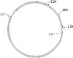
图1为本申请一个实施例提供的单个柔性膜片卷绕构成的血管支架示意图;Fig. 1 is a schematic diagram of a blood vessel stent formed by winding a single flexible membrane provided by an embodiment of the present application;
图2为如图1所示的血管支架的直径扩大结构示意图;FIG. 2 is a schematic diagram of a diameter-enlarged structure of the vascular stent shown in FIG. 1;
图3为如图1所示的血管支架的立体结构示意图;FIG. 3 is a schematic diagram of the three-dimensional structure of the vascular stent shown in FIG. 1;
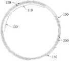
图4为本申请一个实施例提供的多个柔性膜片卷绕构成的血管支架示意图;Fig. 4 is a schematic diagram of a blood vessel stent formed by winding a plurality of flexible membranes provided by an embodiment of the present application;
图5为如图4所示的血管支架的直径扩大结构示意图;FIG. 5 is a schematic diagram of a diameter-enlarged structure of the vascular stent shown in FIG. 4;
图6为本申请一个实施例提供的限位结构的具体结构示意图;Fig. 6 is a specific structural schematic diagram of a position-limiting structure provided by an embodiment of the present application;
图7为如图6所示的限位结构的锁止状态结构示意图;Fig. 7 is a schematic structural diagram of the locking state of the limiting structure as shown in Fig. 6;
图8为本申请另一个实施例提供的限位结构的具体结构示意图;Fig. 8 is a specific structural schematic diagram of a position-limiting structure provided by another embodiment of the present application;
图9为如图8所示的限位结构的锁止状态结构示意图;Fig. 9 is a schematic structural diagram of the locking state of the limiting structure as shown in Fig. 8;
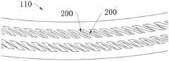
图10为本申请一个实施例提供的限位结构在柔性膜片上的分布结构示意图;Fig. 10 is a schematic diagram of the distribution structure of the limiting structure on the flexible diaphragm provided by an embodiment of the present application;
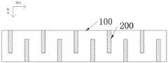
图11为本申请另一个实施例提供的限位结构在柔性膜片上的分布结构示意图。FIG. 11 is a schematic diagram of the distribution structure of the limiting structure on the flexible diaphragm provided by another embodiment of the present application.
附图标号:Figure number:
100、柔性膜片;200、限位结构;100. Flexible diaphragm; 200. Limiting structure;
110、重叠区域;120、相邻重叠区域;130、侧向开口;140、过渡斜面。110, overlapping area; 120, adjacent overlapping area; 130, lateral opening; 140, transition slope.
具体实施方式Detailed ways
为使本发明的上述目的、特征和优点能够更加明显易懂,下面结合附图对本发明的具体实施方式做详细的说明。在下面的描述中阐述了很多具体细节以便于充分理解本发明。但是本发明能够以很多不同于在此描述的其它方式来实施,本领域技术人员可以在不违背本发明内涵的情况下做类似改进,因此本发明不受下面公开的具体实施例的限制。In order to make the above objects, features and advantages of the present invention more comprehensible, specific implementations of the present invention will be described in detail below in conjunction with the accompanying drawings. In the following description, numerous specific details are set forth in order to provide a thorough understanding of the present invention. However, the present invention can be implemented in many other ways different from those described here, and those skilled in the art can make similar improvements without departing from the connotation of the present invention, so the present invention is not limited by the specific embodiments disclosed below.
参阅图1至图11所示,本发明一实施例提供了一种血管支架,所述血管支架包括筒状支架,所述筒状支架包含至少一片柔性膜片100,所述筒状支架的周向方向限定为卷绕方向,至少一片所述柔性膜片200沿着所述卷绕方向卷绕,所述血管支架包括还限位结构200,所述限位结构200设置在所述柔性膜片100上,所述限位结构200用于限制所述柔性膜片100沿着所述筒状支架的直径缩小方向卷绕。1 to 11, an embodiment of the present invention provides a vascular stent, the vascular stent includes a cylindrical stent, the cylindrical stent includes at least one piece of
需要说明的是,所述筒状支架的周向方向包含了正反两个方向,例如参阅图1所示的正时针方向和逆时针方向,在图1中所示的卷绕状态下,正时针方向卷绕会使筒状支架的直径扩大,逆时针方向卷绕会使筒状支架的直径缩小,本领域技术人员可以根据图1理解限位结构200限制柔性膜片100沿着所述筒状支架的直径缩小方向卷绕的具体卷绕方向,其他实施例同理不再赘述。It should be noted that the circumferential direction of the cylindrical bracket includes two directions, positive and negative. For example, refer to the clockwise direction and the counterclockwise direction shown in FIG. 1 . Winding in the clockwise direction will expand the diameter of the cylindrical stent, and winding in the counterclockwise direction will reduce the diameter of the cylindrical stent. Those skilled in the art can understand that the
需要说明的是,柔性膜片100卷绕构成筒状支架的卷绕属于活动的卷绕,也就是说,虽然柔性膜片100构成了结构形式相对稳定的筒状支架,但是柔性膜片100形成层面间接触的相邻层面(表面)之间依旧保持着可相对滑动的能力,而并非将筒状支架的卷绕状态完全定型,所以如果对筒状支架施加外力,例如沿着筒状支架的径向方向由内向外的施加作用力,依旧能够使构成筒状支架的柔性膜片100在外力的作用下继续发生卷绕,扩大筒状支架的直径。It should be noted that the winding of the
因此,当柔性膜片100上设置了限位结构200后,可以利用限位结构200主动限制柔性膜片100的活动卷绕,具体的,该限位结构200能够用来限制柔性膜片100收缩性卷绕,该收缩性卷绕表示为柔性膜片100通过卷绕可以使筒状支架的直径缩小,同时,限位结构200并不会限制或基本不会限制柔性膜片100扩张性卷绕,该扩张性卷绕表示为柔性膜片100通过卷绕可以使筒状支架的直径扩大。限位结构200可以采用多种形式设置在柔性膜片100上,例如所述限位结构200与所述柔性膜片100一体成型、所述限位结构200固定连接在所述柔性膜片100上、以及所述限位结构200通过粘接、卡接等可拆卸方式连接在所述柔性膜片100上,在此不做限定。Therefore, when the
所以,利用限位结构200对柔性膜片100的活动卷绕形成单向限制后,筒状支架(相当于血管支架)便能够以较小直径的卷绕形态输送到血管的目标位置,当筒状支架到达血管的目标位置后,操作人员可以通过球囊等能够实现自动扩张或收缩的部件,在筒状支架的内部向构成其的柔性膜片100施加能够使柔性膜片100扩张卷绕的外力,使柔性膜片100能够通过扩张性卷绕来扩大筒状支架的直径,使筒状支架稳定地贴于血管内壁。Therefore, after the
筒状支架的直径被扩大后,筒状支架会与血管内壁之间形成紧密的贴合,虽然此时血管内壁会反向地对筒状支架施加反作用力,但是筒状支架依旧会借助于限位结构200的限制而保持当前的直径大小,并不会因为血管内壁施加的反作用力而缩小直径,显然,限位结构200的限制功能使筒状支架(相当于血管支架)具备了更强的支撑力,能够在血管中保持与血管内壁形成稳定地的紧密贴合,也能够使筒状支架(相当于血管支架)具备更高的耐疲劳性。After the diameter of the cylindrical stent is enlarged, the cylindrical stent will form a tight fit with the inner wall of the blood vessel. Although the inner wall of the blood vessel will reversely exert a reaction force on the cylindrical stent at this time, the cylindrical stent will still rely on the restraint. The limitation of the position-limiting
限位结构200对柔性膜片100的限位方向可以预先设定,例如可以设定标准的周向限位轨迹,使所述限位结构200沿着所述周向限位轨迹限制所述柔性膜片100的形成层面间接触的相邻重叠区域120之间相互滑动卷绕,其中,所述周向限位轨迹可以限定为垂直于所述筒状支架的轴向,因此限位结构200沿着周向限位轨迹的限制功能,可以保证柔性膜片100仅沿着周向发生卷绕,进而使卷绕形成的筒状支架仅形成径向的结构变化,如径向的扩张,而不影响产生轴向的结构变化,例如筒状支架的长度发生变化,也就是说,筒状支架不会在轴向上因卷绕错位而改变长度。The limit direction of the
限位结构200的功能是限制所述柔性膜片100沿着所述筒状支架的直径缩小方向卷绕,因此只要能够实现该限制功能,限位结构200可以采用任意结构形式,例如,限位结构200可以与柔性膜片100形成可分离的装配形式,或者限位结构200也可以集成在柔性膜片100上并与柔性膜片100构成为一体,在柔性膜片100上设置的限位结构200可以是槽类结构、凸起类结构、齿条结构、绒毛结构等任意形式,本领域技术人员可以根据需求选择合适的结构形式,在此不做限定。The function of the limiting
参阅图6至图9所示,在其中一个实施例中,所述限位结构200可以包括设置在所述重叠区域110上的单向限位齿条,如图6和图7所示,当单向限位齿条的齿为尖刺状时,单向限位齿条的整体可以通过大量微针沿着周向方向连接构成,其中,微针的长度可为10微米至50微米,微针的倾斜角可为20°至90°,微针的制备工艺可以选择可吸收实心微针制备工艺,如LIGA(电铸技术)以及微注塑等,又或者,如图8和图9所示,当单向限位齿条的齿为长条状时,单向限位齿条的整体可以通过大量矩形齿条沿着周向方向连接构成,构成的单向限位齿条类似鱼骨状,其中,矩形齿条可以通过切割形成,切割方法可以采用为聚合物切割工艺,如激光铣切,或者也可以直接在合适的模具中成型。Referring to Figures 6 to 9, in one embodiment, the limiting
因此,形成层面间接触的相邻重叠区域120内的所述单向限位齿条之间能够沿着筒状支架的周向相反两个方向分别相对滑动和相对锁止,继续参阅图7所示,当单向限位齿条通过大量微针沿着周向方向连接构成时,相邻单向限位齿条之间的微针能够形成相互勾连,使其仅能够向一个方向相对滑移,而在另一个方向相对锁止,又或者参阅图9所示,当单向限位齿条通过大量矩形齿条沿着周向方向连接构成时,单向限位齿条的矩形齿条在弯曲内侧能够贴合形成台阶结构,在弯曲外侧能够张开形成爪结构,进而利用爪结构形成相对卡扣,由于台阶结构与爪结构都是单向的,因此能够形成相邻层间的顺结构滑移、以及相邻层间的逆结构锁止。Therefore, the one-way limit racks in the adjacent overlapping
在其中一个实施例中,所述限位结构200也可以包括设置在所述重叠区域110上的单向限位绒毛,单向限位绒毛可以主要应用在静电纺丝聚合物片材或薄膜中,例如单向限位绒毛可以通过织物起绒工艺构成刷毛、抓毛或磨毛等,将静电纺丝纤维向同一方向单向起绒,若柔性膜片100的相邻重叠区域120之间相互运动方向与起绒方向为同向,则相邻重叠区域120之间的摩擦力较低,使相邻重叠区域120能够顺利滑移,若滑移方向与起绒方向相反,则柔性膜片100的相邻重叠区域120之间摩擦力陡增,相邻重叠区域120之间滑移运动受限,使筒状支架的支撑力明显提升。具体的,形成层面间接触的相邻重叠区域120内的所述单向限位绒毛之间能够沿着筒状支架的周向相反两个方向分别具有第一摩擦力和第二摩擦力,所述第一摩擦力和所述第二摩擦力不同,本领域技术人员可以根据需求调整起绒状态,调整第一摩擦力和第二摩擦力之间的差距,进而调整相邻重叠区域120之间沿着不同方向滑移时的顺畅程度和受限程度。In one of the embodiments, the limiting
限位结构200设置在柔性膜片100上可以理解为限位结构200位于柔性膜片100的本身区域内,也可以理解为限位结构200位于柔性膜片100的本身区域外,只是与柔性膜片100形成连接。The setting of the limiting
例如,当限位结构200位于柔性膜片100的本身区域内时,柔性膜片100需要卷绕成闭合的筒状而形成筒状支架,然后借助于柔性膜片100本身区域内的限位结构200发挥限位功能,此时,所述柔性膜片100的至少一部分区域被限定为重叠区域110,参考图4和图5所示,所述柔性膜片100具有重叠区域110,所述柔性膜片100的重叠区域110能够在所述筒状支架中形成层面间接触,而所述限位结构至少部分也可以位于所述重叠区域110内,当所述柔性膜片100的重叠区域110通过卷绕形成层面间接触后,所述柔性膜片100中形成层面间接触的相邻重叠区域120之间便可以利用限位结构200形成相互限制。For example, when the limiting
又例如,限位结构200位于柔性膜片100的本身区域外,只是与柔性膜片100形成连接时,限位结构200可以为连接在柔性膜片100的边缘,并完全处于柔性膜片100的本身区域之外,当所述柔性膜片100通过卷绕形成筒状支架后,限位结构200可以基于柔性膜片100卷绕成的筒状结构与所述柔性膜片100的表面形成层面间接触,进而相对于柔性膜片100的表面发生相互限制,发挥其限位效果。For another example, when the position-limiting
需要说明的是,层面间接触表示的是当柔性膜片100卷绕成筒状支架后,柔性膜片100的不同表面之间会形成层叠的状态,此时柔性膜片100的不同表面之间的接触即为柔性膜片100的层面间接触,例如图1至图5中所示的相邻重叠区域120体现的不同表面之间的层面间接触,该层面间接触可以是同一个柔性膜片100的不同表面之间的层面间接触,也可以是不同柔性膜片100的不同表面之间的层面间接触,这需要根据筒状支架包含的柔性膜片100以及具体的卷绕方式而确定,本领域技术人员可以根据需求合理选择,在此不做限定。It should be noted that the contact between layers means that when the
或者在其中一个实施例中,当限位结构200位于柔性膜片100的本身区域外,只是与柔性膜片100形成连接时,柔性膜片100并不需要卷绕成闭合的筒状而形成筒状支架,,此时也可以借助于柔性膜片100本身区域外的限位结构200发挥限位功能,使构成筒状支架的柔性膜片100不再发生使筒状支架直径缩小的收缩性卷绕,使筒状支架保持为非闭合且直径固定的结构状态。Or in one of the embodiments, when the limiting
筒状支架可以通过一个或多个柔性膜片100卷绕构成,当筒状支架采用的柔性膜片100的数量不同时,柔性膜片100的卷绕形式也具有不同,例如在其中一个实施例中,参阅图1至图3所示,所述柔性膜片100的数量为一个时,所述筒状支架通过一个柔性膜片100卷绕而成,一个所述柔性膜片100上的重叠区域110内的不同部分之间在所述筒状支架中形成层面间接触,在此卷绕方式中,该一个柔性膜片100始终朝着周向一个方向卷绕,柔性膜片100卷绕构成的筒状支架的径向截面上,柔性膜片100的卷绕结构呈螺旋状结构形式,重叠区域110内的不同部分表示的是分布在该一个重叠区域110的不同部分(或称为不同的小区域)。The cylindrical stent can be formed by winding one or more
又或者,在其中一个实施例中,参阅图4和图5所示,所述柔性膜片100的数量为至少两个时,所述筒状支架通过至少两个柔性膜片100卷绕而成,不同所述柔性膜片100上的重叠区域110在所述筒状支架中形成层面间接触,根据筒状支架的结构需求,柔性膜片100可以采用两个、三个或四个不等,继续参阅图4和图5所示,当柔性膜片100为三个时,每个柔性膜片100的周向两端均具有重叠区域110,且根据每个柔性膜片100在卷绕过程中与其他柔性膜片100之间的层面间接触关系,柔性膜片100的重叠区域110可以表示为柔性膜片100的单个表面或全部两个表面,三个柔性膜片100沿着周向方向卷绕后,相邻的柔性膜片100的重叠区域110之间会形成相互之间的层面间接触,然后通过三个柔性膜片100的周向卷绕配合构成筒状支架。Or, in one of the embodiments, as shown in FIG. 4 and FIG. 5 , when the number of the
在多个柔性膜片100卷绕构成筒状支架的结构形式中,每个所述柔性膜片100均可以卷绕构成具有侧向开口130的筒状单元,即该侧向开口130是针对于单片柔性膜片100而言且还未被卷绕构成筒状支架之前所能够显示出来的开口结构,当多个柔性膜片100卷绕成筒状支架后,侧向开口130会被覆盖或封闭,每个柔性膜片100的侧向开口130具有可调节性,即随着柔性膜片100在周向上实施扩张性卷绕或实施收缩性卷绕时,柔性膜片100的侧向开口130都能够相应地扩大角度或缩小角度,例如柔性膜片100的侧向开口130的角度可以在0°至60°之间自由调节,形成侧向开口130的可调节性,此时柔性膜片100为两个或两个以上时,两个或两个以上的柔性膜片100便可以依靠相邻柔性膜片100相互之间的层面间接触构成所述筒状支架。而且,柔性膜片100分别形成的两个或两个以上的侧向开口130可以沿着所述筒状支架的周向均匀分布,两个或两个以上的侧向开口130均匀分布在筒状支架的周向,能够使筒状支架具有均匀的周向力学性能。In the structural form in which a plurality of
继续参阅图1和图4所示,在其中一个实施例中,所述柔性膜片100沿着所述筒状支架周向方向的端部设置有过渡斜面140,该过渡斜面140可以通过对柔性膜片100的周向方向的端部进行削薄处理来实现,而且过渡斜面140的设置位置和数量可以根据柔性膜片100的具体数量和卷绕形式确定,只要保证一个或多个柔性膜片100通过卷绕形成筒状支架,且所述筒状支架能够通过所述过渡斜面140使其外壁或内壁形成平滑的表面即可,形成平滑的表面可以降低对血液流动和血管支架贴壁的影响。Continuing to refer to Fig. 1 and Fig. 4, in one embodiment, the end of the
柔性膜片100可以表示为片材、膜材等,柔性膜片100可以采用聚合物材料,因此,柔性膜片100可以为聚合物片材或聚合物膜材,例如在其中一个实施例中,所述柔性膜片100的材质为可降解高分子材料,可降解高分子材料包括但不限于左旋聚乳酸、消旋聚乳酸等中的一种或多种,本领域技术人员可以根据需求选择,在此不做限定。The
参阅图10和图11所示,在其中一个实施例中,所述限位结构200沿着所述柔性膜片100的周向延伸,多个所述限位结构200沿着所述筒状支架的轴向在所述柔性膜片100上分布,而且,所述限位结构200沿着所述筒状支架周向方向的长度为第一周向长度,所述柔性膜片100沿着所述筒状支架周向方向的长度为第二周向长度,因此,既可以使所述第一周向长度等于所述第二周向长度,也可以使所述第一周向长度小于所述第二周向长度,且多个所述限位结构200沿着所述筒状支架的轴向相互交错。10 and 11, in one embodiment, the limiting
除此之外,根据血管支架的材质、结构以及支撑力性能等各种方面的不同要求,限位结构200可以具有不同的形状、位置、数量以及面积,本领域技术人员可以根据需求选择,在此不做限定。In addition, according to the different requirements of the material, structure and supporting force performance of the vascular stent, the limiting
本发明提供了一种血管支架的制备方法,制备方法包括如下步骤:在柔性膜片100上设置限位结构200,将柔性膜片100卷绕并定型为筒状支架,利用所述限位结构200限制所述柔性膜片100沿着所述筒状支架的直径缩小方向卷绕。卷绕柔性膜片100的时候可以将柔性膜片100包裹在折叠的球囊上形成筒状支架,并在合适的温度进行定型处理,定型处理能够对筒状支架的形态做固定,但是此过程中不涉及压握过程,即筒状支架的内外径不发生变化。The present invention provides a method for preparing a vascular stent. The preparation method includes the following steps: setting a limiting
由于柔性膜片100包裹在折叠的球囊上,由于折叠的球囊还未被充起,因此折叠的球囊上的筒状支架会具备较小的直径,当筒状支架到达血管的目标位置后,操作人员可以通过球囊的自动扩张,在筒状支架的内部向构成其的柔性膜片100施加能够使柔性膜片100扩张卷绕的外力,使柔性膜片100能够通过扩张性卷绕来扩大筒状支架的直径,使筒状支架稳定地贴于血管内壁。Since the
筒状支架的直径被扩大后,筒状支架会与血管内壁之间形成紧密的贴合,虽然此时血管内壁会反向地对筒状支架施加反作用力,但是筒状支架依旧会借助于限位结构200的限制而保持当前的直径大小,并不会因为血管内壁施加的反作用力而缩小直径,显然,限位结构200的限制功能使筒状支架(相当于血管支架)具备了更强的支撑力,能够在血管中保持与血管内壁形成稳定地的紧密贴合,也能够使筒状支架(相当于血管支架)具备更高的耐疲劳性。After the diameter of the cylindrical stent is enlarged, the cylindrical stent will form a tight fit with the inner wall of the blood vessel. Although the inner wall of the blood vessel will reversely exert a reaction force on the cylindrical stent at this time, the cylindrical stent will still rely on the restraint. The limitation of the position-limiting
以上所述实施例的各技术特征可以进行任意的组合,为使描述简洁,未对上述实施例中的各个技术特征所有可能的组合都进行描述,然而,只要这些技术特征的组合不存在矛盾,都应当认为是本说明书记载的范围。The technical features of the above-mentioned embodiments can be combined arbitrarily. To make the description concise, all possible combinations of the technical features in the above-mentioned embodiments are not described. However, as long as there is no contradiction in the combination of these technical features, should be considered as within the scope of this specification.
以上所述实施例仅表达了本发明的几种实施方式,其描述较为具体和详细,但并不能因此而理解为对发明专利范围的限制。应当指出的是,对于本领域的普通技术人员来说,在不脱离本发明构思的前提下,还可以做出若干变形和改进,这些都属于本发明的保护范围。因此,本发明专利的保护范围应以所附权利要求为准。The above-mentioned embodiments only express several implementation modes of the present invention, and the descriptions thereof are relatively specific and detailed, but should not be construed as limiting the patent scope of the invention. It should be noted that those skilled in the art can make several modifications and improvements without departing from the concept of the present invention, and these all belong to the protection scope of the present invention. Therefore, the protection scope of the patent for the present invention should be based on the appended claims.
Claims (15)
Priority Applications (3)
| Application Number | Priority Date | Filing Date | Title |
|---|---|---|---|
| CN202210911128.8ACN115281903A (en) | 2022-07-29 | 2022-07-29 | Blood vessel stent and preparation method thereof |
| PCT/CN2023/108859WO2024022284A1 (en) | 2022-07-29 | 2023-07-24 | Vascular stent and preparation method therefor |
| EP23845494.6AEP4552618A1 (en) | 2022-07-29 | 2023-07-24 | Vascular stent and preparation method therefor |
Applications Claiming Priority (1)
| Application Number | Priority Date | Filing Date | Title |
|---|---|---|---|
| CN202210911128.8ACN115281903A (en) | 2022-07-29 | 2022-07-29 | Blood vessel stent and preparation method thereof |
Publications (1)
| Publication Number | Publication Date |
|---|---|
| CN115281903Atrue CN115281903A (en) | 2022-11-04 |
Family
ID=83825962
Family Applications (1)
| Application Number | Title | Priority Date | Filing Date |
|---|---|---|---|
| CN202210911128.8APendingCN115281903A (en) | 2022-07-29 | 2022-07-29 | Blood vessel stent and preparation method thereof |
Country Status (3)
| Country | Link |
|---|---|
| EP (1) | EP4552618A1 (en) |
| CN (1) | CN115281903A (en) |
| WO (1) | WO2024022284A1 (en) |
Cited By (4)
| Publication number | Priority date | Publication date | Assignee | Title |
|---|---|---|---|---|
| WO2024022284A1 (en)* | 2022-07-29 | 2024-02-01 | 上海微创医疗器械(集团)有限公司 | Vascular stent and preparation method therefor |
| CN118217070A (en)* | 2024-05-22 | 2024-06-21 | 北京华脉泰科医疗器械股份有限公司 | Vascular stent |
| CN119745561A (en)* | 2024-12-31 | 2025-04-04 | 北京博辉瑞进生物科技有限公司 | Artificial fluid pipe |
| CN119745562A (en)* | 2024-12-31 | 2025-04-04 | 北京博辉瑞进生物科技有限公司 | Degradable artificial fluid pipe |
Citations (8)
| Publication number | Priority date | Publication date | Assignee | Title |
|---|---|---|---|---|
| US20020082674A1 (en)* | 1995-09-08 | 2002-06-27 | Anson Anthony Walter | Surgical graft/stent system |
| US20050038497A1 (en)* | 2003-08-11 | 2005-02-17 | Scimed Life Systems, Inc. | Deformation medical device without material deformation |
| US20050049687A1 (en)* | 1999-07-02 | 2005-03-03 | Endotex Interventional Systems, Inc. | Flexible, stretchable coiled-sheet stent |
| US20100122698A1 (en)* | 2008-11-19 | 2010-05-20 | The Nemours Foundation | Neonatal airway stent |
| US20100179640A1 (en)* | 2007-07-07 | 2010-07-15 | Walter Reith | Radially Expandable System For Use In Body Tubes |
| US20140249614A1 (en)* | 2009-03-06 | 2014-09-04 | The Regents Of The University Of California | Thin film vascular stent and biocompatible surface treatment |
| CN107280826A (en)* | 2017-06-01 | 2017-10-24 | 北京工业大学 | Joinery and its construction brace rod intravascular stent |
| CN218652144U (en)* | 2022-07-29 | 2023-03-21 | 上海微创医疗器械(集团)有限公司 | Blood vessel support |
Family Cites Families (5)
| Publication number | Priority date | Publication date | Assignee | Title |
|---|---|---|---|---|
| WO1994021196A2 (en)* | 1993-03-18 | 1994-09-29 | C.R. Bard, Inc. | Endovascular stents |
| ES2449890T3 (en)* | 2009-09-02 | 2014-03-21 | Lifecell Corporation | Vascular grafts obtained from acellular tissue matrices |
| CN108852574B (en)* | 2018-07-27 | 2024-04-05 | 北京华脉泰科医疗器械股份有限公司 | Tectorial membrane support restraint device |
| CN209678767U (en)* | 2019-01-31 | 2019-11-26 | 东莞立德生物医疗有限公司 | A kind of vascular stent with coiled structure |
| CN115281903A (en)* | 2022-07-29 | 2022-11-04 | 上海微创医疗器械(集团)有限公司 | Blood vessel stent and preparation method thereof |
- 2022
- 2022-07-29CNCN202210911128.8Apatent/CN115281903A/enactivePending
- 2023
- 2023-07-24EPEP23845494.6Apatent/EP4552618A1/enactivePending
- 2023-07-24WOPCT/CN2023/108859patent/WO2024022284A1/ennot_activeCeased
Patent Citations (8)
| Publication number | Priority date | Publication date | Assignee | Title |
|---|---|---|---|---|
| US20020082674A1 (en)* | 1995-09-08 | 2002-06-27 | Anson Anthony Walter | Surgical graft/stent system |
| US20050049687A1 (en)* | 1999-07-02 | 2005-03-03 | Endotex Interventional Systems, Inc. | Flexible, stretchable coiled-sheet stent |
| US20050038497A1 (en)* | 2003-08-11 | 2005-02-17 | Scimed Life Systems, Inc. | Deformation medical device without material deformation |
| US20100179640A1 (en)* | 2007-07-07 | 2010-07-15 | Walter Reith | Radially Expandable System For Use In Body Tubes |
| US20100122698A1 (en)* | 2008-11-19 | 2010-05-20 | The Nemours Foundation | Neonatal airway stent |
| US20140249614A1 (en)* | 2009-03-06 | 2014-09-04 | The Regents Of The University Of California | Thin film vascular stent and biocompatible surface treatment |
| CN107280826A (en)* | 2017-06-01 | 2017-10-24 | 北京工业大学 | Joinery and its construction brace rod intravascular stent |
| CN218652144U (en)* | 2022-07-29 | 2023-03-21 | 上海微创医疗器械(集团)有限公司 | Blood vessel support |
Cited By (5)
| Publication number | Priority date | Publication date | Assignee | Title |
|---|---|---|---|---|
| WO2024022284A1 (en)* | 2022-07-29 | 2024-02-01 | 上海微创医疗器械(集团)有限公司 | Vascular stent and preparation method therefor |
| CN118217070A (en)* | 2024-05-22 | 2024-06-21 | 北京华脉泰科医疗器械股份有限公司 | Vascular stent |
| CN118217070B (en)* | 2024-05-22 | 2024-08-02 | 北京华脉泰科医疗器械股份有限公司 | Vascular stent |
| CN119745561A (en)* | 2024-12-31 | 2025-04-04 | 北京博辉瑞进生物科技有限公司 | Artificial fluid pipe |
| CN119745562A (en)* | 2024-12-31 | 2025-04-04 | 北京博辉瑞进生物科技有限公司 | Degradable artificial fluid pipe |
Also Published As
| Publication number | Publication date |
|---|---|
| WO2024022284A1 (en) | 2024-02-01 |
| EP4552618A1 (en) | 2025-05-14 |
Similar Documents
| Publication | Publication Date | Title |
|---|---|---|
| CN115281903A (en) | Blood vessel stent and preparation method thereof | |
| US11413437B2 (en) | Expandable introducer assembly | |
| ES2829906T3 (en) | Stent Delivery Systems with Deployment Assist | |
| AU2013312748B2 (en) | Retractable sheath devices, systems, and methods | |
| EP1931411B1 (en) | Methods for making catheters with lubricious linings | |
| CN102655824B (en) | Medical stent | |
| JP6359968B2 (en) | Abductable sheath device, system and method | |
| JP7605858B2 (en) | Stents | |
| JP2931010B2 (en) | Vascular prosthesis | |
| CN109803713B (en) | Catheter tube and method of making the same | |
| US20030135268A1 (en) | Secure stent for maintaining a lumenal opening | |
| CN109260527B (en) | Porous material with fibrillar microstructure and fracturable coating | |
| BR112012000678A2 (en) | tube with reversible narrowing properties | |
| US20070208276A1 (en) | Adjustable catheter tip | |
| BR112016018920B1 (en) | highly flexible stent | |
| CN218652144U (en) | Blood vessel support | |
| JP7235763B2 (en) | Inflatable medical balloon containing continuous fibers | |
| JP5834536B2 (en) | Catheter having tapered structure with different lumen and outer circumference | |
| CN219481261U (en) | Balloon for interventional operation and balloon catheter | |
| CN116474179A (en) | Polymer tubes with controlled orientation | |
| JP2022054780A (en) | Balloon for catheter, balloon catheter, and manufacturing method of balloon for catheter | |
| CN119139057B (en) | Tendon pullback honeycomb duct and use method thereof | |
| JP7547885B2 (en) | Medical Equipment | |
| CN115500992A (en) | Ear nasal cavity stent, stent pushing device and stent expansion device |
Legal Events
| Date | Code | Title | Description |
|---|---|---|---|
| PB01 | Publication | ||
| PB01 | Publication | ||
| SE01 | Entry into force of request for substantive examination | ||
| SE01 | Entry into force of request for substantive examination |