CN115281585A - Stay wire driving device of flexible controllable apparatus - Google Patents
Stay wire driving device of flexible controllable apparatusDownload PDFInfo
- Publication number
- CN115281585A CN115281585ACN202210771507.1ACN202210771507ACN115281585ACN 115281585 ACN115281585 ACN 115281585ACN 202210771507 ACN202210771507 ACN 202210771507ACN 115281585 ACN115281585 ACN 115281585A
- Authority
- CN
- China
- Prior art keywords
- lead screw
- motor
- flexible
- side plates
- synchronous wheel
- Prior art date
- Legal status (The legal status is an assumption and is not a legal conclusion. Google has not performed a legal analysis and makes no representation as to the accuracy of the status listed.)
- Pending
Links
- 230000007246mechanismEffects0.000claimsabstractdescription51
- 238000009434installationMethods0.000claimsabstractdescription15
- 230000001360synchronised effectEffects0.000claimsdescription82
- 230000000712assemblyEffects0.000claimsdescription7
- 238000000429assemblyMethods0.000claimsdescription7
- 230000033001locomotionEffects0.000description18
- 230000005540biological transmissionEffects0.000description16
- 238000005452bendingMethods0.000description15
- 238000003780insertionMethods0.000description5
- 230000037431insertionEffects0.000description5
- 238000010586diagramMethods0.000description4
- 238000004891communicationMethods0.000description2
- 230000008878couplingEffects0.000description2
- 238000010168coupling processMethods0.000description2
- 238000005859coupling reactionMethods0.000description2
- 238000003745diagnosisMethods0.000description2
- 239000000463materialSubstances0.000description2
- 238000012986modificationMethods0.000description2
- 230000004048modificationEffects0.000description2
- 229910000831SteelInorganic materials0.000description1
- 230000008859changeEffects0.000description1
- 230000000694effectsEffects0.000description1
- 239000003365glass fiberSubstances0.000description1
- 238000000034methodMethods0.000description1
- 230000002093peripheral effectEffects0.000description1
- 229920001084poly(chloroprene)Polymers0.000description1
- 229920002635polyurethanePolymers0.000description1
- 239000004814polyurethaneSubstances0.000description1
- 238000011897real-time detectionMethods0.000description1
- 230000003252repetitive effectEffects0.000description1
- 239000010959steelSubstances0.000description1
- 230000009278visceral effectEffects0.000description1
Images


Classifications
- A—HUMAN NECESSITIES
- A61—MEDICAL OR VETERINARY SCIENCE; HYGIENE
- A61B—DIAGNOSIS; SURGERY; IDENTIFICATION
- A61B1/00—Instruments for performing medical examinations of the interior of cavities or tubes of the body by visual or photographical inspection, e.g. endoscopes; Illuminating arrangements therefor
- A61B1/00147—Holding or positioning arrangements
- A61B1/0016—Holding or positioning arrangements using motor drive units
- A—HUMAN NECESSITIES
- A61—MEDICAL OR VETERINARY SCIENCE; HYGIENE
- A61B—DIAGNOSIS; SURGERY; IDENTIFICATION
- A61B1/00—Instruments for performing medical examinations of the interior of cavities or tubes of the body by visual or photographical inspection, e.g. endoscopes; Illuminating arrangements therefor
- A61B1/005—Flexible endoscopes
- A61B1/0051—Flexible endoscopes with controlled bending of insertion part
- A61B1/0057—Constructional details of force transmission elements, e.g. control wires
Landscapes
- Health & Medical Sciences (AREA)
- Life Sciences & Earth Sciences (AREA)
- Surgery (AREA)
- Nuclear Medicine, Radiotherapy & Molecular Imaging (AREA)
- Biomedical Technology (AREA)
- Optics & Photonics (AREA)
- Pathology (AREA)
- Radiology & Medical Imaging (AREA)
- Biophysics (AREA)
- Engineering & Computer Science (AREA)
- Physics & Mathematics (AREA)
- Heart & Thoracic Surgery (AREA)
- Medical Informatics (AREA)
- Molecular Biology (AREA)
- Animal Behavior & Ethology (AREA)
- General Health & Medical Sciences (AREA)
- Public Health (AREA)
- Veterinary Medicine (AREA)
- Manipulator (AREA)
Abstract
Description
Translated fromChinese技术领域technical field
本发明涉及医疗器械技术领域,尤其涉及一种柔性可控器械的拉线驱动装置。The invention relates to the technical field of medical instruments, in particular to a pull wire driving device for a flexible and controllable instrument.
背景技术Background technique
末端可控的柔性医疗器械可以为医疗领域中应用的内窥镜,如支气管镜、尿道镜、十二指肠镜、胆道镜、肾盂镜等纤细的柔性电子内窥镜。内窥镜是一种广泛用于临床检查和诊断的医疗器械,由鞘、插入部及其各自前端的柔性可控器械、光源及镜头等组成。柔性可控器械在进行弯曲变形时,一般是通过牵拉内置于柔性可控器械的拉线来实现的。The end-controllable flexible medical device can be an endoscope used in the medical field, such as a bronchoscope, a urethroscope, a duodenoscope, a choledochoscope, a pyeloscope, and other slender and flexible electronic endoscopes. An endoscope is a medical device widely used in clinical examination and diagnosis. It consists of a sheath, an insertion part and a flexible controllable device at its front end, a light source and a lens. When the flexible controllable device undergoes bending deformation, it is generally realized by pulling the pull wire built into the flexible controllable device.
目前,柔性可控器械弯曲姿态的控制因减小体积的需求多采用驱动电机旋转驱动拉线方式。也有方案或通过联轴器连接的驱动电机和丝杠实现线性运动式驱动拉线,以达到更精准的控制效果,但驱动电机、联轴器和丝杠构成的驱动机构存在长度较长,控制柔性可控器械弯曲的驱动机构整体占用空间大且结构不紧凑等不足。At present, the control of the bending posture of flexible and controllable instruments often uses the drive motor to rotate and drive the pull wire due to the need to reduce the volume. There are also solutions or a drive motor and a lead screw connected by a coupling to realize a linear motion drive cable to achieve a more precise control effect, but the drive mechanism composed of the drive motor, coupling and lead screw has a long length and flexible control. The driving mechanism of the controllable instrument bending takes up a large space and is not compact in structure.
发明内容Contents of the invention
本发明提供一种柔性可控器械的线性运动式拉线驱动装置,用以解决现有技术中柔性手术器械机器人的驱动机构整体占用空间大且结构不紧凑的问题。The invention provides a linear motion pull wire drive device for a flexible and controllable instrument, which is used to solve the problems in the prior art that the drive mechanism of a flexible surgical instrument robot occupies a large space and is not compact in structure.
本发明提供一种柔性可控器械的拉线驱动装置,包括:The invention provides a pull wire driving device for a flexible and controllable instrument, comprising:
安装座,所述安装座包括相对设置的两个侧板;An installation base, the installation base includes two oppositely arranged side plates;
多个驱动机构,所述驱动机构包括电机和丝杠,所述丝杠与所述电机的输出端连接,所述电机安装于所述安装座的一个侧板上,所述电机位于所述两个侧板之间,所述丝杠的两端分别安装于所述两个侧板,所述电机用于驱动所述丝杠与所述电机的输出端同步旋转,所述丝杠用于驱动柔性可控器械拉线沿所述丝杠的轴向移动。A plurality of drive mechanisms, the drive mechanism includes a motor and a lead screw, the lead screw is connected to the output end of the motor, the motor is installed on a side plate of the mounting seat, and the motor is located on the two sides Between the two side plates, the two ends of the lead screw are respectively installed on the two side plates, the motor is used to drive the lead screw to rotate synchronously with the output end of the motor, and the lead screw is used to drive The flexible and controllable instrument pull wire moves along the axial direction of the lead screw.
根据本发明提供的一种柔性可控器械的拉线驱动装置,所述驱动机构还包括:According to a pull wire drive device for a flexible controllable instrument provided by the present invention, the drive mechanism further includes:
第一同步轮、第二同步轮和同步带,所述第一同步轮与所述电机的输出端连接,所述丝杠的一端与所述第二同步轮连接,所述同步带套设于所述第一同步轮和所述第二同步轮的外周,所述第一同步轮、所述第二同步轮和所述同步带位于同一个所述侧板的外侧。The first synchronous wheel, the second synchronous wheel and the synchronous belt, the first synchronous wheel is connected to the output end of the motor, one end of the screw is connected to the second synchronous wheel, and the synchronous belt is sleeved on The outer peripheries of the first synchronous wheel and the second synchronous wheel, the first synchronous wheel, the second synchronous wheel and the synchronous belt are located on the outer side of the same side plate.
根据本发明提供的一种柔性可控器械的拉线驱动装置,所述电机的输出端设置有第一齿轮,所述丝杠的一端设置有第二齿轮,所述第一齿轮和所述第二齿轮啮合。According to a pull wire driving device for a flexible controllable instrument provided by the present invention, the output end of the motor is provided with a first gear, one end of the screw is provided with a second gear, and the first gear and the second gears meshing.
根据本发明提供的一种柔性可控器械的拉线驱动装置,所述侧板设置有多个安装孔,所述多个安装孔与所述多个驱动机构的所述丝杠一一对应,所述丝杠的端部贯穿所述安装孔位于所述侧板的外侧。According to a pull wire driving device for a flexible controllable instrument provided by the present invention, the side plate is provided with a plurality of installation holes, and the plurality of installation holes correspond to the lead screws of the plurality of drive mechanisms one by one, so The end of the lead screw passes through the installation hole and is located outside the side plate.
根据本发明提供的一种柔性可控器械的拉线驱动装置,所述多个安装孔均匀布置于所述侧板。According to the cable drive device for a flexible and controllable instrument provided by the present invention, the plurality of installation holes are evenly arranged on the side plate.
根据本发明提供的一种柔性可控器械的拉线驱动装置,所述驱动机构还包括:According to a pull wire drive device for a flexible controllable instrument provided by the present invention, the drive mechanism further includes:
拉线连接件,所述拉线连接件安装于所述丝杠,所述拉线连接件用于连接所述柔性可控器械拉线。A pull wire connector, the pull wire connector is installed on the lead screw, and the pull wire connector is used to connect the pull wire of the flexible controllable instrument.
根据本发明提供的一种柔性可控器械的拉线驱动装置,所述驱动机构还包括:According to a pull wire drive device for a flexible controllable instrument provided by the present invention, the drive mechanism further includes:
丝杠螺母连接件,所述丝杠螺母连接件安装在所述丝杠的丝杠螺母上,所述丝杠螺母套设于所述丝杠,所述丝杠螺母连接件位于所述两个侧板之间;A lead screw nut connector, the lead screw nut connector is installed on the lead screw nut of the lead screw, the lead screw nut is sleeved on the lead screw, and the lead screw nut connector is located between the two between side panels;
拉力传感器,所述拉力传感器安装于所述丝杠螺母连接件,所述拉力传感器与所述拉线连接件连接,所述拉力传感器用于测量所述拉线连接件连接的所述柔性可控器械拉线上的实时拉力。A tension sensor, the tension sensor is installed on the lead screw nut connector, the tension sensor is connected to the pull wire connector, and the tension sensor is used to measure the flexible controllable instrument pull wire connected to the pull wire connector real-time pull on .
根据本发明提供的一种柔性可控器械的拉线驱动装置,还包括:According to the pull wire driving device of a flexible and controllable instrument provided by the present invention, it also includes:
多个导向组件,所述导向组件包括至少两个导柱,所述导柱的两端分别安装于所述两个侧板,所述多个导向组件与所述多个驱动机构一一对应,所述丝杠螺母连接件设有通孔,所述导柱贯穿所述通孔。A plurality of guide assemblies, the guide assembly includes at least two guide columns, the two ends of the guide columns are respectively installed on the two side plates, the plurality of guide assemblies correspond to the plurality of drive mechanisms one by one, The lead screw nut connecting piece is provided with a through hole, and the guide post passes through the through hole.
根据本发明提供的一种柔性可控器械的拉线驱动装置,所述电机安装于所述两个侧板中的一个,所述两个侧板中的另一个用于安装柔性可控器械拉线安装座组件。According to a pull-wire drive device for a flexible and controllable instrument provided by the present invention, the motor is installed on one of the two side plates, and the other of the two side plates is used for installing the pull-wire of the flexible and controllable instrument seat assembly.
本发明提供的柔性可控器械的拉线驱动装置,通过将多个驱动机构位于安装座的两个侧板之间,电机驱动丝杠同步旋转,进而带动丝杠上的柔性可控器械拉线移动,实现对柔性可控器械弯曲姿态的精准控制,拉线驱动装置整体占用空间小且结构紧凑,有助于实现柔性手术器械机器人的小型化。拉线驱动装置采用线性运动式驱动拉线,避免电机旋转式驱动拉线在电机换向旋转时造成的柔性可控器械拉线松弛造成的柔性可控器械弯曲延迟,线性运动式驱动拉线实现控制柔性可控器械拉线更加精准,精度更高。The pull wire driving device of the flexible and controllable instrument provided by the present invention, by placing a plurality of driving mechanisms between the two side plates of the mounting seat, the motor drives the lead screw to rotate synchronously, and then drives the flexible controllable instrument pull wire on the lead screw to move, The precise control of the bending posture of the flexible and controllable instrument is realized, and the overall footprint of the cable drive device is small and the structure is compact, which helps to realize the miniaturization of the flexible surgical instrument robot. The cable drive device adopts a linear motion drive cable to avoid bending delay of the flexible controllable instrument caused by the cable slack of the flexible controllable instrument caused by the motor rotation drive cable when the motor reverses rotation, and the linear motion drive cable realizes the control of the flexible controllable instrument The pull wire is more precise and the precision is higher.
附图说明Description of drawings
为了更清楚地说明本发明或现有技术中的技术方案,下面将对实施例或现有技术描述中所需要使用的附图作一简单地介绍,显而易见地,下面描述中的附图是本发明的一些实施例,对于本领域普通技术人员来讲,在不付出创造性劳动的前提下,还可以根据这些附图获得其他的附图。In order to more clearly illustrate the present invention or the technical solutions in the prior art, the accompanying drawings that need to be used in the description of the embodiments or the prior art will be briefly introduced below. Obviously, the accompanying drawings in the following description are the present invention. For some embodiments of the invention, those skilled in the art can also obtain other drawings based on these drawings without creative effort.
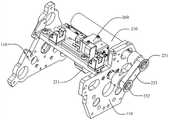
图1是本发明提供的柔性可控器械的拉线驱动装置的立体结构示意图之一;Fig. 1 is one of the three-dimensional structural schematic diagrams of the pull wire driving device of the flexible controllable instrument provided by the present invention;
图2是本发明提供的柔性可控器械的拉线驱动装置的立体结构示意图之二;Fig. 2 is the second schematic view of the three-dimensional structure of the pull wire driving device of the flexible controllable instrument provided by the present invention;
图3是本发明提供的柔性可控器械的拉线驱动装置的立体结构示意图之三;Fig. 3 is the third schematic diagram of the three-dimensional structure of the pull wire driving device of the flexible controllable instrument provided by the present invention;
图4是本发明提供的柔性可控器械的拉线驱动装置的截面示意图;Fig. 4 is a schematic cross-sectional view of the pull wire driving device of the flexible controllable instrument provided by the present invention;
图5是本发明提供的柔性可控器械的拉线驱动装置的局部结构示意图之一;Fig. 5 is one of the partial structural schematic diagrams of the pull wire driving device of the flexible controllable instrument provided by the present invention;
图6是本发明提供的柔性可控器械的拉线驱动装置的局部结构示意图之二。Fig. 6 is the second schematic diagram of the partial structure of the cable driving device of the flexible controllable instrument provided by the present invention.
附图标记:Reference signs:
110:侧板;120:底板;110: side plate; 120: bottom plate;
210:电机;220:丝杠;231:第一同步轮;232:第二同步轮;233:同步带;240:拉线连接件;250:丝杠螺母;251:丝杠螺母连接件;260:拉力传感器;270:导柱。210: motor; 220: lead screw; 231: first synchronous wheel; 232: second synchronous wheel; 233: synchronous belt; 240: cable connector; 250: lead screw nut; 251: lead screw nut connector; 260: Tension sensor; 270: guide post.
具体实施方式Detailed ways
为使本发明的目的、技术方案和优点更加清楚,下面将结合本发明中的附图,对本发明中的技术方案进行清楚、完整地描述,显然,所描述的实施例是本发明一部分实施例,而不是全部的实施例。基于本发明中的实施例,本领域普通技术人员在没有作出创造性劳动前提下所获得的所有其他实施例,都属于本发明保护的范围。In order to make the purpose, technical solutions and advantages of the present invention clearer, the technical solutions in the present invention will be clearly and completely described below in conjunction with the accompanying drawings in the present invention. Obviously, the described embodiments are part of the embodiments of the present invention , but not all examples. Based on the embodiments of the present invention, all other embodiments obtained by persons of ordinary skill in the art without creative efforts fall within the protection scope of the present invention.
在本发明实施例的描述中,需要说明的是,术语“中心”、“上”、“下”、“前”、“后”、“左”、“右”、“内”、“外”等指示的方位或位置关系为基于附图所示的方位或位置关系,仅是为了便于描述本发明实施例和简化描述,而不是指示或暗示所指的装置或元件必须具有特定的方位、以特定的方位构造和操作,因此不能理解为对本发明实施例的限制。此外,术语“第一”、“第二”、“第三”仅用于描述目的,而不能理解为指示或暗示相对重要性。In the description of the embodiments of the present invention, it should be noted that the terms "center", "upper", "lower", "front", "rear", "left", "right", "inner", "outer" The orientation or positional relationship indicated by etc. is based on the orientation or positional relationship shown in the drawings, and is only for the convenience of describing the embodiment of the present invention and simplifying the description, rather than indicating or implying that the referred device or element must have a specific orientation, so as to Specific orientation configurations and operations, therefore, should not be construed as limitations on embodiments of the present invention. In addition, the terms "first", "second", and "third" are used for descriptive purposes only, and should not be construed as indicating or implying relative importance.
在本发明实施例的描述中,需要说明的是,除非另有明确的规定和限定,术语“相连”、“连接”应做广义理解,例如,可以是固定连接,也可以是可拆卸连接,或一体连接;可以是机械连接,也可以是电连接,或有线通信连接,或无线通信连接;可以是直接相连,也可以通过中间媒介间接相连。对于本领域的普通技术人员而言,可以具体情况理解上述术语在本发明实施例中的具体含义。In the description of the embodiments of the present invention, it should be noted that unless otherwise specified and limited, the terms "connected" and "connected" should be understood in a broad sense, for example, it can be a fixed connection or a detachable connection, Or integrated connection; it can be mechanical connection, electrical connection, wired communication connection, or wireless communication connection; it can be directly connected or indirectly connected through an intermediary. Those of ordinary skill in the art can understand the specific meanings of the above terms in the embodiments of the present invention in specific situations.
在本发明实施例中,除非另有明确的规定和限定,第一特征在第二特征“上”或“下”可以是第一和第二特征直接接触,或第一和第二特征通过中间媒介间接接触。而且,第一特征在第二特征“之上”、“上方”和“上面”可是第一特征在第二特征正上方或斜上方,或仅仅表示第一特征水平高度高于第二特征。第一特征在第二特征“之下”、“下方”和“下面”可以是第一特征在第二特征正下方或斜下方,或仅仅表示第一特征水平高度小于第二特征。In the embodiments of the present invention, unless otherwise specified and limited, the first feature may be in direct contact with the first feature or the first feature and the second feature may pass through the middle of the second feature. Media indirect contact. Moreover, "above", "above" and "above" the first feature on the second feature may mean that the first feature is directly above or obliquely above the second feature, or simply means that the first feature is higher in level than the second feature. "Below", "beneath" and "beneath" the first feature may mean that the first feature is directly below or obliquely below the second feature, or simply means that the first feature is less horizontally than the second feature.
在本说明书的描述中,参考术语“一个实施例”、“一些实施例”、“示例”、“具体示例”、或“一些示例”等的描述意指结合该实施例或示例描述的具体特征、结构、材料或者特点包含于本发明实施例的至少一个实施例或示例中。在本说明书中,对上述术语的示意性表述不必须针对的是相同的实施例或示例。而且,描述的具体特征、结构、材料或者特点可以在任一个或多个实施例或示例中以合适的方式结合。此外,在不相互矛盾的情况下,本领域的技术人员可以将本说明书中描述的不同实施例或示例以及不同实施例或示例的特征进行结合和组合。In the description of this specification, descriptions referring to the terms "one embodiment", "some embodiments", "example", "specific examples", or "some examples" mean that specific features described in connection with the embodiment or example , structure, material or feature is included in at least one embodiment or example of the embodiments of the present invention. In this specification, the schematic representations of the above terms are not necessarily directed to the same embodiment or example. Furthermore, the described specific features, structures, materials or characteristics may be combined in any suitable manner in any one or more embodiments or examples. In addition, those skilled in the art can combine and combine different embodiments or examples and features of different embodiments or examples described in this specification without conflicting with each other.
下面结合图1至图6描述本发明实施例的柔性可控器械的拉线驱动装置。The pull-wire driving device of the flexible and controllable instrument according to the embodiment of the present invention will be described below with reference to FIGS. 1 to 6 .
末端可控的柔性医疗器械可以插入人体体腔和脏器内腔进行直接观察、诊断或治疗,该类柔性医疗器械的鞘及插入部前端设置有柔性可控器械。Flexible medical devices with controllable ends can be inserted into human body cavities and visceral cavities for direct observation, diagnosis or treatment. The sheath and front end of the insertion part of such flexible medical devices are provided with flexible controllable devices.
柔性可控器械上均匀有多根拉线,通过拉线驱动装置驱动多根拉线前后移动,可控制柔性可控器械的弯曲姿态,使得柔性医疗器械的末端可控。There are evenly a plurality of pull wires on the flexible controllable device, and the pull wire driving device drives the multiple pull wires to move back and forth, so that the bending posture of the flexible controllable device can be controlled, so that the end of the flexible medical device is controllable.
末端可控的柔性医疗器械可以为医疗领域中应用的内窥镜,如支气管镜、尿道镜、十二指肠镜、胆道镜、肾盂镜等纤细的柔性电子内窥镜。The end-controllable flexible medical device can be an endoscope used in the medical field, such as a bronchoscope, a urethroscope, a duodenoscope, a choledochoscope, a pyeloscope, and other slender and flexible electronic endoscopes.
如图1所示,本发明实施例提供的柔性可控器械的拉线驱动装置包括:安装座和多个驱动机构。安装座包括相对设置的两个侧板110,两个侧板110用于安装支撑拉线驱动装置的多个驱动机构。As shown in FIG. 1 , the pull-wire driving device of the flexible and controllable instrument provided by the embodiment of the present invention includes: a mounting base and a plurality of driving mechanisms. The mounting seat includes two
如图3所示,安装座还可以包括至少一个底板120,底板120连接与两个侧板110之间。As shown in FIG. 3 , the mounting seat may further include at least one
驱动机构包括电机210、丝杠220和导柱270,电机210是驱动机构的动力源,电机210可以将电能转换为机械能,并将机械能传递到丝杠220;丝杠220是驱动机构的传动元件,丝杠220将机械能传递到柔性可控器械拉线,以实现驱动机构中的电机210可驱动柔性可控器械拉线移动,控制柔性可控器械的弯曲姿态,导柱270是驱动机构的导向机构。The driving mechanism includes a
在该实施例中,驱动机构的丝杠220与电机210的输出端连接,电机210安装于一个侧板上,电机210位于两个侧板110之间,丝杠220的两端分别安装于两个侧板110。In this embodiment, the
丝杠220可以将旋转运动转换成线性运动,或将扭矩转换成轴向反复作用力,同时兼具高精度、可逆性和高效率的特点。The
丝杠220与电机210的输出端连接,电机210用于驱动丝杠220与电机210的输出端同步旋转,同时丝杠220可以将电机210的输出端所输出的旋转运动转换成线性运动。The
在该实施例中,丝杠220将电机210的输出端所输出的旋转运动转换成线性运动驱动柔性可控器械拉线运动,柔性可控器械拉线沿丝杠的轴向移动,通过不同拉线的前后移动,进而控制柔性可控器械的弯曲姿态。In this embodiment, the
如图5所示,安装座上相对设置的两个侧板110限定出了一个半封闭的安装空间,驱动机构的电机210和丝杠220均位于该安装空间内,安装座为多个驱动机构提供固定及支撑功能,驱动机构实现对柔性可控器械拉线的精准控制的同时,拉线驱动装置整体占用空间小且结构紧凑,有助于实现柔性手术器械机器人的小型化。As shown in Figure 5, the two
在实际执行中,可以根据柔性可控器械中柔性可控器械拉线的数量,调整拉线驱动装置中驱动机构的数量。In actual implementation, the number of driving mechanisms in the wire driving device can be adjusted according to the number of pull wires in the flexible and controllable device.
例如,柔性可控器械内部设有3根柔性可控器械拉线,通过改变3根柔性可控器械拉线的前后位置控制柔性可控器械的弯曲姿态,拉线驱动装置对应设置3个驱动机构,1个驱动机构的丝杠220连接1根柔性可控器械拉线,3个电机210可分别驱动柔性可控器械的3根柔性可控器械拉线移动,控制柔性可控器械的弯曲姿态。For example, there are three flexible and controllable instrument cables inside the flexible and controllable instrument, and the bending posture of the flexible and controllable instrument is controlled by changing the front and rear positions of the three flexible and controllable instrument cables. The
在该实施例中,柔性可控器械可以为内窥镜上设置的柔性可控器械,也可以为其他末端可控的柔性医疗器械上设置的柔性可控器械。In this embodiment, the flexible controllable instrument may be a flexible controllable instrument provided on an endoscope, or may be a flexible controllable instrument provided on other end-controllable flexible medical instruments.
根据本发明实施例提供的拉线驱动装置,多个驱动机构位于安装座的两个侧板110之间,电机210驱动丝杠220同步旋转,进而带动丝杠220上的柔性可控器械拉线移动,实现对柔性可控器械弯曲姿态的精准控制,拉线驱动装置整体占用空间小且结构紧凑,有助于实现柔性手术器械机器人的小型化。According to the cable driving device provided in the embodiment of the present invention, multiple driving mechanisms are located between the two
在一些实施例中,拉线驱动装置的驱动机构还包括:第一同步轮231、第二同步轮232和同步带233。In some embodiments, the driving mechanism of the cable driving device further includes: a first
在该实施例中,第一同步轮231与电机210的输出端连接,丝杠220的一端与第二同步轮232连接,同步带233套设于第一同步轮231和第二同步轮232的外周,第一同步轮231、第二同步轮232和同步带233位于同一个侧板110的外侧。In this embodiment, the first
如图3所示,电机210可以安装于安装座的其中一个侧板110上,电机210的输出端位于该侧板110的外侧,其中,侧板110的内侧为位于两个侧板110之间的一侧,侧板110的外侧为位于两个侧板110之外的一侧。As shown in FIG. 3 , the
第一同步轮231与位于侧板110的外侧的电机210的输出端连接,电机210工作,电机210的输出端转动,带动第一同步轮231转动。The first
在该实施例中,丝杠220的一端与第二同步轮232连接,丝杠220上与第二同步轮232连接的一端位于电机210的输出端所位于的侧板110上。In this embodiment, one end of the
同步带233套设于第一同步轮231和第二同步轮232的外周,电机210工作时,通过第一同步轮231、第二同步轮232和同步带233组成的同步带传动组件,电机210的输出端带动丝杠220同步旋转。The
同步带233可以是以钢丝绳或玻璃纤维为强力层,外覆以聚氨酯或氯丁橡胶的环形带,同步带233的内周可以制成齿状,相应的,第一同步轮231和第二同步轮232的外周设置为与同步带233的内周的齿状相啮合的齿状。The
在实际执行中,同步带233可以实现第一同步轮231和第二同步轮232的同步传动,也可以通过调整第一同步轮231和第二同步轮232的外周尺寸,实现第一同步轮231和第二同步轮232的变速传动。In actual implementation, the
在该实施例中,电机210与丝杠220之间的传动通过两个同步轮和一条同步带233实现,使用同步轮进行动力传动,可以使得拉线驱动装置的结构更加紧凑。In this embodiment, the transmission between the
可以理解的是,第一同步轮231、第二同步轮232和同步带233位于同一个侧板110的外侧,该侧板110将同步带传动组件和电机210、丝杠220所处空间分隔开来,保证同步带传动组件的传动稳定有效的同时,驱动装置的结构更加紧凑、有序。It can be understood that the first
在一些实施例中,电机210的输出端设置有第一齿轮,丝杠220的一端设置有第二齿轮,第一齿轮和第二齿轮啮合。In some embodiments, the output end of the
在该实施例中,电机210通过齿轮传动方式,由电机210的输出端带动丝杠220同步旋转。In this embodiment, the
齿轮是指轮缘上有轮齿连续啮合传递运动和动力的机械元件,轮齿是齿轮上的用于啮合的凸起部分。A gear refers to a mechanical element with teeth on the rim that continuously mesh to transmit motion and power, and the teeth are the raised parts on the gear for meshing.
在该实施例中,第一齿轮设置于电机210的输出端,第二齿轮设置于丝杠220的一端,第一齿轮和第二齿轮啮合,电机210工作,电机210的输出端带动第一齿轮转动,第一齿轮带动第二齿轮转动,实现电机210的输出端带动丝杠220同步旋转。In this embodiment, the first gear is arranged at the output end of the
在实际执行中,第一齿轮和第二齿轮可以位于安装座的两个侧板110之间,第一齿轮和第二齿轮位于安装座的同一个侧板110的外侧。In actual implementation, the first gear and the second gear may be located between two
例如,电机210可以安装于安装座的其中一个侧板110,电机210的输出端位于该侧板110的外侧,第一齿轮设置于电机210的输出端。For example, the
在该实施例中,丝杠220的一端也位于该侧板110的外侧,第二齿轮设置于丝杠220的一端,第一齿轮和第二齿轮相互啮合,电机210的输出端带动丝杠220同步旋转。In this embodiment, one end of the
可以理解的是,齿轮传动方式可以实现电机210的输出端和丝杠220之间的同步传动,也可以通过调整第一齿轮和第二齿轮的外周尺寸,实现电机210的输出端和丝杠220之间的变速传动。It can be understood that the gear transmission mode can realize synchronous transmission between the output end of the
在一些实施例中,侧板110设置有多个安装孔,多个安装孔与多个驱动机构的丝杠220一一对应,丝杠220的端部贯穿安装孔位于侧板110的外侧。In some embodiments, the
在该实施例中,安装座的两个侧板110的每个侧板110均设置有多个安装孔,两个侧板110相对设置,每个侧板110上的多个安装孔的位置也是正对的。In this embodiment, each
每个侧板110上的多个安装孔与多个驱动机构的丝杠220一一对应,例如,拉线驱动装置包括3个驱动机构,有3个丝杠220,每个侧板110上设置有对应的3个安装孔。A plurality of mounting holes on each
在实际执行中,丝杠220的端部贯穿安装孔位于侧板110的外侧,一个丝杠220有两个端部,丝杠220的两个端部分别贯穿两个侧板110上正对的两个安装孔,丝杠220的端部位于侧板110的外侧,同步轮或齿轮等传动组件可以安装于丝杠220的端部,以使拉线驱动装置的结构更加紧凑。In actual implementation, the end of the
在一些实施例中,多个安装孔均匀布置于侧板110。In some embodiments, a plurality of mounting holes are uniformly arranged on the
在该实施例中,多个安装孔均匀布置于侧板110,每个驱动机构的丝杠220贯穿对应的安装孔,丝杠220在安装座内部空间均匀分布,拉线驱动装置的结构更加规整,便于安装和维修。In this embodiment, a plurality of mounting holes are evenly arranged on the
在实际执行中,侧板110上均匀布置的多个安装孔,每个安装孔与其相邻的两个安装孔形成的夹角相同。In actual implementation, the multiple installation holes are evenly arranged on the
例如,拉线驱动装置包括3个驱动机构,安装座的每个侧板110上设置有3个安装孔,每个丝杠220的两个端部分别贯穿两个侧板110上正对的两个安装孔。For example, the pull wire driving device includes 3 driving mechanisms, 3 mounting holes are provided on each
如图4所示,在侧板110上的3个安装孔呈120°均匀分布,丝杠220贯穿对应的安装孔,每个安装孔与其相邻的两个安装孔形成的夹角为60°,3个安装孔的连线构成等边三角形。As shown in Figure 4, the three mounting holes on the
再例如,拉线驱动装置包括4个驱动机构,安装座的每个侧板110上设置有4个安装孔,每个丝杠220的两个端部分别贯穿两个侧板110上正对的两个安装孔。For another example, the pull wire driving device includes 4 driving mechanisms, and each
在侧板110上的4个安装孔呈90°均匀分布,每个安装孔与其相邻的两个安装孔形成的夹角为90°,4个安装孔的连线构成正方形。The 4 mounting holes on the
在一些实施例中,驱动机构还包括拉线连接件240。In some embodiments, the drive mechanism also includes a
在该实施例中,如图2所示,拉线连接件240安装于丝杠220,拉线连接件240用于连接柔性可控器械拉线。In this embodiment, as shown in FIG. 2 , the
驱动机构的丝杠220与电机210的输出端连接,电机210带动丝杠220与电机210的输出端同步旋转,丝杠220转动时,安装于丝杠220的拉线连接件240沿着丝杠220轴向的直线运动,进而使柔性可控器械拉线前后移动,控制柔性可控器械的弯曲姿态。The
在实际执行中,拉线连接件240安装于丝杠220,丝杠220的端部可以贯穿安装孔位于侧板110的外侧,拉线连接件240连接在丝杠螺母连接件251上;相应的,同步轮或齿轮等传动组件可以安装于丝杠220,位于两个侧板110中的另一个侧板110的外侧。In actual implementation, the
在一些实施例中,驱动机构还包括丝杠螺母250、丝杠螺母连接件251和拉力传感器260。In some embodiments, the driving mechanism further includes a
在该实施例中,如图6所示,丝杠螺母250套设于丝杠220,丝杠螺母250位于两个侧板110之间,丝杠螺母连接件251连接在丝杠螺母250上,拉力传感器260安装于丝杠螺母连接件251上,拉力传感器260与拉线连接件240连接,拉力传感器260用于测量拉线连接件240连接的柔性可控器械拉线上的实时拉力。In this embodiment, as shown in FIG. 6 , the
丝杠螺母250套设于丝杠220,丝杠220随着电机210的输出端同步旋转时,丝杠螺母250在丝杠220上移动,拉力传感器260可以与固定柔性可控器械拉线的拉线连接件240进行卡扣连接。The
丝杠螺母250在丝杠220上移动距离与丝杠220的转动相关,丝杠220的转动带动柔性可控器械拉线的移动,拉力传感器260可以在电机210通过丝杠220驱动柔性可控器械拉线时,实时检测柔性可控器械拉线上的实时拉力。The moving distance of the
在一些实施例中,拉线驱动装置还包括多个导向组件。In some embodiments, the cable drive device further includes a plurality of guide assemblies.
在该实施例中,每个导向组件包括至少两个导柱270,导柱270的两端分别安装于两个侧板110,多个导向组件与多个驱动机构一一对应,丝杠螺母连接件251设有通孔,导柱270贯穿通孔。In this embodiment, each guide assembly includes at least two
可以理解的是,导向组件的导柱270对丝杠220上的丝杠螺母连接件251的移动起到导向作用。It can be understood that the
在该实施例中,导柱270的两端分别安装于两个侧板110,导向组件也是布置在安装座内的,拉线驱动装置的结构更加紧凑,导柱270还可以对安装座起到一定的支撑作用。In this embodiment, the two ends of the
多个导向组件与多个驱动机构一一对应,每个驱动机构的丝杠220上的丝杠螺母250对应一组导向组件,丝杠螺母连接件251设有供导柱270贯穿的通孔,丝杠220旋转时,丝杠螺母连接件251沿着丝杠220和导柱270移动。A plurality of guide assemblies corresponds to a plurality of driving mechanisms one by one, the
在一些实施例中,电机210安装于两个侧板110中的一个,两个侧板110中的另一个用于安装拉线的柔性可控器械拉线安装座组件。In some embodiments, the
如图3所示,安装座的两个侧板110为驱动机构提供固定及支撑功能,电机210安装于两个侧板110中的一个上,柔性可控器械安装座组件安装于两个侧板110中的另一个上。As shown in Figure 3, the two
在该实施例中,柔性可控器械拉线安装座组件用于安装固定柔性医疗器械的鞘和插入部及其各自前端的柔性可控器械的拉线,电机210和柔性可控器械拉线安装座组件分别安装于安装座的不同侧板110上,提升安装座的稳定性。In this embodiment, the flexible controllable instrument pull wire mount assembly is used to install and fix the sheath and the insertion part of the flexible medical instrument and the pull wires of the flexible controllable instrument at their respective front ends, and the
下面介绍一个具体的实施例。A specific embodiment is introduced below.
柔性医疗器械的鞘和插入部的柔性可控器械内部均匀圆周分布3根柔性可控器械拉线,拉线驱动装置包括3个驱动机构,每根柔性可控器械拉线与对应的驱动机构的丝杠220上的拉线连接件240相连。The sheath of the flexible medical device and the flexible and controllable device of the insertion part are evenly distributed on the inside of the flexible and controllable device. Three flexible and controllable device pull wires are evenly distributed around the circumference. The
每个驱动机构包括一个电机210、一个丝杠220、两个导柱270、第一同步轮231、第二同步轮232和同步带233。Each driving mechanism includes a
两个导柱270设置于丝杠220的两侧,第一同步轮231和第二同步轮232分别设置于电机210的输出端和丝杠220的一端,同步带233套设于第一同步轮231和第二同步轮232的外周。Two
在安装座的侧板110上的3个安装孔呈120°均匀分布,每个丝杠220的两个端部分别贯穿两个侧板110上正对的两个安装孔,丝杠220在安装座内均匀布置。The three mounting holes on the
电机210与丝杠220之间的传动通过两个同步轮和一条同步带233实现,拉线驱动装置整体占用空间小且结构紧凑。The transmission between the
下面对本发明实施例提供的柔性手术器械机器人进行描述,下文描述的柔性手术器械机器人包括上文描述的拉线驱动装置。The flexible surgical instrument robot provided by the embodiment of the present invention is described below, and the flexible surgical instrument robot described below includes the pull wire driving device described above.
本发明实施例提供的柔性手术器械机器人包括:柔性医疗器械和柔性可控器械的拉线驱动装置等,柔性医疗器械设置有鞘和插入部及其各自前端的柔性可控器械等,柔性可控器械的弯曲姿态可由拉线驱动装置和拉线控制。The flexible surgical instrument robot provided by the embodiment of the present invention includes: a flexible medical instrument and a pull wire drive device of the flexible controllable instrument, etc., the flexible medical instrument is provided with a sheath, an insertion part and flexible controllable instruments at their respective front ends, etc., and the flexible controllable instrument The bending posture can be controlled by the pull wire driving device and the pull wire.
在该实施例中,多个驱动机构与多根柔性可控器械拉线一一对应,柔性可控器械拉线的第一端连接柔性可控器械,柔性可控器械拉线的第二端与驱动机构的丝杠220连接。In this embodiment, a plurality of driving mechanisms correspond to a plurality of flexible controllable instrument pull wires, the first end of the flexible controllable instrument pull wire is connected to the flexible controllable instrument, and the second end of the flexible controllable instrument pull wire is connected to the drive mechanism.
根据本发明实施例提供的拉线驱动装置,多个驱动机构位于安装座的两个侧板110之间,电机210驱动丝杠220同步旋转,进而带动丝杠220上的柔性可控器械拉线移动,实现对柔性可控器械弯曲姿态的精准控制,拉线驱动装置整体占用空间小且结构紧凑,有助于实现柔性手术器械机器人的小型化。拉线驱动装置采用线性运动式驱动拉线,避免电机旋转式驱动拉线在电机换向旋转时造成的柔性可控器械拉线松弛造成的柔性可控器械弯曲延迟。线性运动式拉丝实现控制柔性可控器械拉线更加精准,精度更高。According to the cable driving device provided in the embodiment of the present invention, multiple driving mechanisms are located between the two
最后应说明的是:以上实施例仅用以说明本发明的技术方案,而非对其限制;尽管参照前述实施例对本发明进行了详细的说明,本领域的普通技术人员应当理解:其依然可以对前述各实施例所记载的技术方案进行修改,或者对其中部分技术特征进行等同替换;而这些修改或者替换,并不使相应技术方案的本质脱离本发明各实施例技术方案的精神和范围。Finally, it should be noted that: the above embodiments are only used to illustrate the technical solutions of the present invention, rather than to limit them; although the present invention has been described in detail with reference to the foregoing embodiments, those of ordinary skill in the art should understand that: it can still be Modifications are made to the technical solutions described in the foregoing embodiments, or equivalent replacements are made to some of the technical features; and these modifications or replacements do not make the essence of the corresponding technical solutions deviate from the spirit and scope of the technical solutions of the various embodiments of the present invention.
Claims (9)
Priority Applications (2)
| Application Number | Priority Date | Filing Date | Title |
|---|---|---|---|
| CN202210771507.1ACN115281585A (en) | 2022-06-30 | 2022-06-30 | Stay wire driving device of flexible controllable apparatus |
| PCT/CN2022/125005WO2024000922A1 (en) | 2022-06-30 | 2022-10-13 | Pull wire-driving apparatus for flexible controllable device |
Applications Claiming Priority (1)
| Application Number | Priority Date | Filing Date | Title |
|---|---|---|---|
| CN202210771507.1ACN115281585A (en) | 2022-06-30 | 2022-06-30 | Stay wire driving device of flexible controllable apparatus |
Publications (1)
| Publication Number | Publication Date |
|---|---|
| CN115281585Atrue CN115281585A (en) | 2022-11-04 |
Family
ID=83821427
Family Applications (1)
| Application Number | Title | Priority Date | Filing Date |
|---|---|---|---|
| CN202210771507.1APendingCN115281585A (en) | 2022-06-30 | 2022-06-30 | Stay wire driving device of flexible controllable apparatus |
Country Status (2)
| Country | Link |
|---|---|
| CN (1) | CN115281585A (en) |
| WO (1) | WO2024000922A1 (en) |
Cited By (2)
| Publication number | Priority date | Publication date | Assignee | Title |
|---|---|---|---|---|
| CN117814726A (en)* | 2023-11-28 | 2024-04-05 | 中国科学院自动化研究所 | Pull wire driving device of flexible controllable instrument |
| WO2025138391A1 (en)* | 2023-12-29 | 2025-07-03 | 中国科学院自动化研究所 | Advancing system for flexible-end-controllable medical device and medical device |
Citations (10)
| Publication number | Priority date | Publication date | Assignee | Title |
|---|---|---|---|---|
| WO2007007873A1 (en)* | 2005-07-14 | 2007-01-18 | Olympus Medical Systems Corp. | Endoscope |
| CN103112438A (en)* | 2013-01-28 | 2013-05-22 | 浙江万安科技股份有限公司 | Inhaul cable type electronic parking transmission mechanism |
| CN103157170A (en)* | 2013-02-25 | 2013-06-19 | 中国科学院自动化研究所 | Blood vessel interventional operation conduit or guide wire control device based on two-point clamping |
| CN206673775U (en)* | 2017-04-26 | 2017-11-24 | 田明霞 | A kind of parallel axes driver |
| CN108186171A (en)* | 2017-12-28 | 2018-06-22 | 中国科学院深圳先进技术研究院 | A kind of bionic hand device and robot |
| CN209564207U (en)* | 2018-10-09 | 2019-11-01 | 成都博恩思医学机器人有限公司 | A kind of operating robot |
| CN113040918A (en)* | 2021-03-17 | 2021-06-29 | 山东大学 | Surgical robot for removing limited space bone lesion area |
| CN114098972A (en)* | 2020-08-28 | 2022-03-01 | 中国科学院沈阳自动化研究所 | A surgical instrument that can be used in a minimally invasive surgical robot |
| CN114305540A (en)* | 2022-03-08 | 2022-04-12 | 极限人工智能有限公司 | Instrument driving module, operation power device and split type operation device |
| CN216768861U (en)* | 2022-01-24 | 2022-06-17 | 深圳市万至达电机制造有限公司 | Driving device of telescopic flexible screen and telescopic flexible screen comprising same |
Family Cites Families (8)
| Publication number | Priority date | Publication date | Assignee | Title |
|---|---|---|---|---|
| DE102016223614A1 (en)* | 2016-11-29 | 2018-05-30 | Schaeffler Technologies AG & Co. KG | Linearaktorik |
| CN111012500B (en)* | 2018-10-09 | 2022-02-22 | 成都博恩思医学机器人有限公司 | Surgical robot |
| CN110260122A (en)* | 2019-06-20 | 2019-09-20 | 歌尔股份有限公司 | Lifting device for camera and mobile terminal |
| CN110537945B (en)* | 2019-09-20 | 2024-07-30 | 沈阳术驰医疗科技有限公司 | Minimally invasive surgical instrument |
| CN113017837B (en)* | 2021-03-16 | 2022-06-10 | 山东大学 | Concentric tube operation mechanism and ophthalmic operation device |
| CN113303914B (en)* | 2021-06-23 | 2022-10-25 | 山东大学 | A minimally invasive surgical robot for skull base tumor resection through nasal cavity |
| CN113712666B (en)* | 2021-08-03 | 2023-10-27 | 复旦大学 | A flexible continuum surgical robot |
| CN216098910U (en)* | 2021-08-11 | 2022-03-22 | 术锐(上海)科技有限公司 | Continuum instrument and robot |
- 2022
- 2022-06-30CNCN202210771507.1Apatent/CN115281585A/enactivePending
- 2022-10-13WOPCT/CN2022/125005patent/WO2024000922A1/ennot_activeCeased
Patent Citations (10)
| Publication number | Priority date | Publication date | Assignee | Title |
|---|---|---|---|---|
| WO2007007873A1 (en)* | 2005-07-14 | 2007-01-18 | Olympus Medical Systems Corp. | Endoscope |
| CN103112438A (en)* | 2013-01-28 | 2013-05-22 | 浙江万安科技股份有限公司 | Inhaul cable type electronic parking transmission mechanism |
| CN103157170A (en)* | 2013-02-25 | 2013-06-19 | 中国科学院自动化研究所 | Blood vessel interventional operation conduit or guide wire control device based on two-point clamping |
| CN206673775U (en)* | 2017-04-26 | 2017-11-24 | 田明霞 | A kind of parallel axes driver |
| CN108186171A (en)* | 2017-12-28 | 2018-06-22 | 中国科学院深圳先进技术研究院 | A kind of bionic hand device and robot |
| CN209564207U (en)* | 2018-10-09 | 2019-11-01 | 成都博恩思医学机器人有限公司 | A kind of operating robot |
| CN114098972A (en)* | 2020-08-28 | 2022-03-01 | 中国科学院沈阳自动化研究所 | A surgical instrument that can be used in a minimally invasive surgical robot |
| CN113040918A (en)* | 2021-03-17 | 2021-06-29 | 山东大学 | Surgical robot for removing limited space bone lesion area |
| CN216768861U (en)* | 2022-01-24 | 2022-06-17 | 深圳市万至达电机制造有限公司 | Driving device of telescopic flexible screen and telescopic flexible screen comprising same |
| CN114305540A (en)* | 2022-03-08 | 2022-04-12 | 极限人工智能有限公司 | Instrument driving module, operation power device and split type operation device |
Cited By (2)
| Publication number | Priority date | Publication date | Assignee | Title |
|---|---|---|---|---|
| CN117814726A (en)* | 2023-11-28 | 2024-04-05 | 中国科学院自动化研究所 | Pull wire driving device of flexible controllable instrument |
| WO2025138391A1 (en)* | 2023-12-29 | 2025-07-03 | 中国科学院自动化研究所 | Advancing system for flexible-end-controllable medical device and medical device |
Also Published As
| Publication number | Publication date |
|---|---|
| WO2024000922A1 (en) | 2024-01-04 |
Similar Documents
| Publication | Publication Date | Title |
|---|---|---|
| CN115281585A (en) | Stay wire driving device of flexible controllable apparatus | |
| CN108603395B (en) | Wellbore and/or pipe pulling tool and propulsion module for pulling wire and/or fiber optic cable | |
| WO2021062636A1 (en) | Robot and integrated joint thereof | |
| CN2894605Y (en) | Electric bending endoscopy instrument | |
| CN104783752A (en) | Large-diameter-changing-ratio miniature gastrointestinal tract robot mechanism | |
| CN100496376C (en) | endoscope | |
| US20200157886A1 (en) | A pulling tool for use in a wellbore and/or tubing and a propulsion module of a pulling tool | |
| CN106510603A (en) | Rotatable endoscope apparatus | |
| CN119283010B (en) | Linear drive device and robot | |
| WO2023051285A1 (en) | Two-degree-of-freedom actuator, mechanical arm and robot | |
| JP2000089131A (en) | Electronic endoscope device | |
| CN116714015A (en) | Quaternion joint snake-shaped manipulator based on gear linkage | |
| CN217510469U (en) | Adjustable Smart Laryngoscope | |
| CN211693390U (en) | Electrically-driven rotary power unit and quadruped robot applying same | |
| CN109973593B (en) | Planetary gear speed increaser | |
| CN219452785U (en) | Transmission mechanism and driving device | |
| CN117717468A (en) | Hand rehabilitation exoskeleton | |
| RU2012106631A (en) | Articulated Robot Wrist | |
| JP2010264063A (en) | Endoscopic apparatus | |
| CN212360664U (en) | A coaxial multi-output deceleration drive device | |
| CN204828505U (en) | Eccentric input cavity planet gear | |
| ITMI20000705A1 (en) | GEARBOX INCLUDING A FIRST STAGE IN CROWN AND ENDLESS SCREW AND A SECOND STAGE WITH AN EPICYCLOIDAL GROUP | |
| CN210714033U (en) | tower safety system | |
| CN222592646U (en) | Improved tensioner | |
| CN222600029U (en) | Soft light board and control system thereof |
Legal Events
| Date | Code | Title | Description |
|---|---|---|---|
| PB01 | Publication | ||
| PB01 | Publication | ||
| SE01 | Entry into force of request for substantive examination | ||
| SE01 | Entry into force of request for substantive examination |