CN115281447A - Height adjustable platform and associated mechanism - Google Patents
Height adjustable platform and associated mechanismDownload PDFInfo
- Publication number
- CN115281447A CN115281447ACN202210974101.3ACN202210974101ACN115281447ACN 115281447 ACN115281447 ACN 115281447ACN 202210974101 ACN202210974101 ACN 202210974101ACN 115281447 ACN115281447 ACN 115281447A
- Authority
- CN
- China
- Prior art keywords
- display
- hinge
- arm
- configuration
- assembly
- Prior art date
- Legal status (The legal status is an assumption and is not a legal conclusion. Google has not performed a legal analysis and makes no representation as to the accuracy of the status listed.)
- Pending
Links
- 230000007246mechanismEffects0.000titleclaimsabstractdescription109
- 230000008859changeEffects0.000claimsdescription10
- 230000007704transitionEffects0.000abstractdescription17
- 238000003860storageMethods0.000description28
- 239000000725suspensionSubstances0.000description26
- 238000013519translationMethods0.000description17
- 238000006073displacement reactionMethods0.000description11
- 230000000712assemblyEffects0.000description7
- 238000000429assemblyMethods0.000description7
- 230000008878couplingEffects0.000description7
- 238000010168coupling processMethods0.000description7
- 238000005859coupling reactionMethods0.000description7
- 230000009471actionEffects0.000description6
- 238000000034methodMethods0.000description5
- 238000011012sanitizationMethods0.000description3
- 238000009434installationMethods0.000description2
- 230000014759maintenance of locationEffects0.000description2
- 238000004519manufacturing processMethods0.000description2
- 238000013459approachMethods0.000description1
- 230000036772blood pressureEffects0.000description1
- 238000009472formulationMethods0.000description1
- 238000003780insertionMethods0.000description1
- 230000037431insertionEffects0.000description1
- 230000001788irregularEffects0.000description1
- 239000000203mixtureSubstances0.000description1
- 238000012544monitoring processMethods0.000description1
- 238000004091panningMethods0.000description1
- 230000008569processEffects0.000description1
- 239000000126substanceSubstances0.000description1
Images


Classifications
- A—HUMAN NECESSITIES
- A47—FURNITURE; DOMESTIC ARTICLES OR APPLIANCES; COFFEE MILLS; SPICE MILLS; SUCTION CLEANERS IN GENERAL
- A47B—TABLES; DESKS; OFFICE FURNITURE; CABINETS; DRAWERS; GENERAL DETAILS OF FURNITURE
- A47B13/00—Details of tables or desks
- A47B13/08—Table tops; Rims therefor
- A47B13/081—Movable, extending, sliding table tops
- A—HUMAN NECESSITIES
- A47—FURNITURE; DOMESTIC ARTICLES OR APPLIANCES; COFFEE MILLS; SPICE MILLS; SUCTION CLEANERS IN GENERAL
- A47B—TABLES; DESKS; OFFICE FURNITURE; CABINETS; DRAWERS; GENERAL DETAILS OF FURNITURE
- A47B21/00—Tables or desks for office equipment, e.g. typewriters, keyboards
- A47B21/02—Tables or desks for office equipment, e.g. typewriters, keyboards with vertical adjustable parts
- A—HUMAN NECESSITIES
- A47—FURNITURE; DOMESTIC ARTICLES OR APPLIANCES; COFFEE MILLS; SPICE MILLS; SUCTION CLEANERS IN GENERAL
- A47B—TABLES; DESKS; OFFICE FURNITURE; CABINETS; DRAWERS; GENERAL DETAILS OF FURNITURE
- A47B21/00—Tables or desks for office equipment, e.g. typewriters, keyboards
- A47B21/03—Tables or desks for office equipment, e.g. typewriters, keyboards with substantially horizontally extensible or adjustable parts other than drawers, e.g. leaves
- A47B21/0314—Platforms for supporting office equipment
- A—HUMAN NECESSITIES
- A47—FURNITURE; DOMESTIC ARTICLES OR APPLIANCES; COFFEE MILLS; SPICE MILLS; SUCTION CLEANERS IN GENERAL
- A47B—TABLES; DESKS; OFFICE FURNITURE; CABINETS; DRAWERS; GENERAL DETAILS OF FURNITURE
- A47B21/00—Tables or desks for office equipment, e.g. typewriters, keyboards
- A47B21/04—Tables or desks for office equipment, e.g. typewriters, keyboards characterised by means for holding or fastening typewriters or computer equipment
- A—HUMAN NECESSITIES
- A47—FURNITURE; DOMESTIC ARTICLES OR APPLIANCES; COFFEE MILLS; SPICE MILLS; SUCTION CLEANERS IN GENERAL
- A47B—TABLES; DESKS; OFFICE FURNITURE; CABINETS; DRAWERS; GENERAL DETAILS OF FURNITURE
- A47B3/00—Folding or stowable tables
- A—HUMAN NECESSITIES
- A47—FURNITURE; DOMESTIC ARTICLES OR APPLIANCES; COFFEE MILLS; SPICE MILLS; SUCTION CLEANERS IN GENERAL
- A47B—TABLES; DESKS; OFFICE FURNITURE; CABINETS; DRAWERS; GENERAL DETAILS OF FURNITURE
- A47B5/00—Suspended or hinged panels forming a table; Wall tables
- A—HUMAN NECESSITIES
- A47—FURNITURE; DOMESTIC ARTICLES OR APPLIANCES; COFFEE MILLS; SPICE MILLS; SUCTION CLEANERS IN GENERAL
- A47B—TABLES; DESKS; OFFICE FURNITURE; CABINETS; DRAWERS; GENERAL DETAILS OF FURNITURE
- A47B5/00—Suspended or hinged panels forming a table; Wall tables
- A47B5/02—Suspended or hinged panels forming a table; Wall tables detachable
- A—HUMAN NECESSITIES
- A47—FURNITURE; DOMESTIC ARTICLES OR APPLIANCES; COFFEE MILLS; SPICE MILLS; SUCTION CLEANERS IN GENERAL
- A47B—TABLES; DESKS; OFFICE FURNITURE; CABINETS; DRAWERS; GENERAL DETAILS OF FURNITURE
- A47B5/00—Suspended or hinged panels forming a table; Wall tables
- A47B5/04—Suspended or hinged panels forming a table; Wall tables foldable
- A—HUMAN NECESSITIES
- A47—FURNITURE; DOMESTIC ARTICLES OR APPLIANCES; COFFEE MILLS; SPICE MILLS; SUCTION CLEANERS IN GENERAL
- A47B—TABLES; DESKS; OFFICE FURNITURE; CABINETS; DRAWERS; GENERAL DETAILS OF FURNITURE
- A47B9/00—Tables with tops of variable height
- A47B9/02—Tables with tops of variable height with balancing device, e.g. by springs, by weight
- A—HUMAN NECESSITIES
- A47—FURNITURE; DOMESTIC ARTICLES OR APPLIANCES; COFFEE MILLS; SPICE MILLS; SUCTION CLEANERS IN GENERAL
- A47B—TABLES; DESKS; OFFICE FURNITURE; CABINETS; DRAWERS; GENERAL DETAILS OF FURNITURE
- A47B9/00—Tables with tops of variable height
- A47B9/12—Tables with tops of variable height with flexible height-adjusting means, e.g. rope, chain
- F—MECHANICAL ENGINEERING; LIGHTING; HEATING; WEAPONS; BLASTING
- F16—ENGINEERING ELEMENTS AND UNITS; GENERAL MEASURES FOR PRODUCING AND MAINTAINING EFFECTIVE FUNCTIONING OF MACHINES OR INSTALLATIONS; THERMAL INSULATION IN GENERAL
- F16M—FRAMES, CASINGS OR BEDS OF ENGINES, MACHINES OR APPARATUS, NOT SPECIFIC TO ENGINES, MACHINES OR APPARATUS PROVIDED FOR ELSEWHERE; STANDS; SUPPORTS
- F16M11/00—Stands or trestles as supports for apparatus or articles placed thereon ; Stands for scientific apparatus such as gravitational force meters
- F16M11/02—Heads
- F16M11/04—Means for attachment of apparatus; Means allowing adjustment of the apparatus relatively to the stand
- F16M11/06—Means for attachment of apparatus; Means allowing adjustment of the apparatus relatively to the stand allowing pivoting
- F16M11/10—Means for attachment of apparatus; Means allowing adjustment of the apparatus relatively to the stand allowing pivoting around a horizontal axis
- F—MECHANICAL ENGINEERING; LIGHTING; HEATING; WEAPONS; BLASTING
- F16—ENGINEERING ELEMENTS AND UNITS; GENERAL MEASURES FOR PRODUCING AND MAINTAINING EFFECTIVE FUNCTIONING OF MACHINES OR INSTALLATIONS; THERMAL INSULATION IN GENERAL
- F16M—FRAMES, CASINGS OR BEDS OF ENGINES, MACHINES OR APPARATUS, NOT SPECIFIC TO ENGINES, MACHINES OR APPARATUS PROVIDED FOR ELSEWHERE; STANDS; SUPPORTS
- F16M11/00—Stands or trestles as supports for apparatus or articles placed thereon ; Stands for scientific apparatus such as gravitational force meters
- F16M11/20—Undercarriages with or without wheels
- F16M11/2007—Undercarriages with or without wheels comprising means allowing pivoting adjustment
- F16M11/2014—Undercarriages with or without wheels comprising means allowing pivoting adjustment around a vertical axis
- F—MECHANICAL ENGINEERING; LIGHTING; HEATING; WEAPONS; BLASTING
- F16—ENGINEERING ELEMENTS AND UNITS; GENERAL MEASURES FOR PRODUCING AND MAINTAINING EFFECTIVE FUNCTIONING OF MACHINES OR INSTALLATIONS; THERMAL INSULATION IN GENERAL
- F16M—FRAMES, CASINGS OR BEDS OF ENGINES, MACHINES OR APPARATUS, NOT SPECIFIC TO ENGINES, MACHINES OR APPARATUS PROVIDED FOR ELSEWHERE; STANDS; SUPPORTS
- F16M11/00—Stands or trestles as supports for apparatus or articles placed thereon ; Stands for scientific apparatus such as gravitational force meters
- F16M11/20—Undercarriages with or without wheels
- F16M11/24—Undercarriages with or without wheels changeable in height or length of legs, also for transport only, e.g. by means of tubes screwed into each other
- F—MECHANICAL ENGINEERING; LIGHTING; HEATING; WEAPONS; BLASTING
- F16—ENGINEERING ELEMENTS AND UNITS; GENERAL MEASURES FOR PRODUCING AND MAINTAINING EFFECTIVE FUNCTIONING OF MACHINES OR INSTALLATIONS; THERMAL INSULATION IN GENERAL
- F16M—FRAMES, CASINGS OR BEDS OF ENGINES, MACHINES OR APPARATUS, NOT SPECIFIC TO ENGINES, MACHINES OR APPARATUS PROVIDED FOR ELSEWHERE; STANDS; SUPPORTS
- F16M11/00—Stands or trestles as supports for apparatus or articles placed thereon ; Stands for scientific apparatus such as gravitational force meters
- F16M11/42—Stands or trestles as supports for apparatus or articles placed thereon ; Stands for scientific apparatus such as gravitational force meters with arrangement for propelling the support stands on wheels
- A—HUMAN NECESSITIES
- A47—FURNITURE; DOMESTIC ARTICLES OR APPLIANCES; COFFEE MILLS; SPICE MILLS; SUCTION CLEANERS IN GENERAL
- A47B—TABLES; DESKS; OFFICE FURNITURE; CABINETS; DRAWERS; GENERAL DETAILS OF FURNITURE
- A47B13/00—Details of tables or desks
- A47B13/02—Underframes
- A47B13/023—Underframes with a central column
- A47B2013/025—Underframes with a central column having radial feet assembled to the base of the column
- A—HUMAN NECESSITIES
- A47—FURNITURE; DOMESTIC ARTICLES OR APPLIANCES; COFFEE MILLS; SPICE MILLS; SUCTION CLEANERS IN GENERAL
- A47B—TABLES; DESKS; OFFICE FURNITURE; CABINETS; DRAWERS; GENERAL DETAILS OF FURNITURE
- A47B13/00—Details of tables or desks
- A47B13/02—Underframes
- A47B2013/026—Underframes having three or four legs connected in a central knot
- A47B2013/027—Underframes having three or four legs connected in a central knot without additional connecting element
- A—HUMAN NECESSITIES
- A47—FURNITURE; DOMESTIC ARTICLES OR APPLIANCES; COFFEE MILLS; SPICE MILLS; SUCTION CLEANERS IN GENERAL
- A47B—TABLES; DESKS; OFFICE FURNITURE; CABINETS; DRAWERS; GENERAL DETAILS OF FURNITURE
- A47B21/00—Tables or desks for office equipment, e.g. typewriters, keyboards
- A47B21/03—Tables or desks for office equipment, e.g. typewriters, keyboards with substantially horizontally extensible or adjustable parts other than drawers, e.g. leaves
- A47B21/0314—Platforms for supporting office equipment
- A47B2021/0321—Keyboard supports
- A47B2021/0335—Keyboard supports mounted under the worksurface
- A47B2021/035—Keyboard supports mounted under the worksurface having double articulated arms
- A—HUMAN NECESSITIES
- A47—FURNITURE; DOMESTIC ARTICLES OR APPLIANCES; COFFEE MILLS; SPICE MILLS; SUCTION CLEANERS IN GENERAL
- A47B—TABLES; DESKS; OFFICE FURNITURE; CABINETS; DRAWERS; GENERAL DETAILS OF FURNITURE
- A47B2200/00—General construction of tables or desks
- A47B2200/0011—Underframes
- A47B2200/002—Legs
- A47B2200/0021—Tables or desks of the single column type
- A47B2200/0022—Central column leg assembly composed of several segments
- A—HUMAN NECESSITIES
- A47—FURNITURE; DOMESTIC ARTICLES OR APPLIANCES; COFFEE MILLS; SPICE MILLS; SUCTION CLEANERS IN GENERAL
- A47B—TABLES; DESKS; OFFICE FURNITURE; CABINETS; DRAWERS; GENERAL DETAILS OF FURNITURE
- A47B2200/00—General construction of tables or desks
- A47B2200/0066—Workstations
- A47B2200/0076—Vertical technical column supporting office equipment
- F—MECHANICAL ENGINEERING; LIGHTING; HEATING; WEAPONS; BLASTING
- F16—ENGINEERING ELEMENTS AND UNITS; GENERAL MEASURES FOR PRODUCING AND MAINTAINING EFFECTIVE FUNCTIONING OF MACHINES OR INSTALLATIONS; THERMAL INSULATION IN GENERAL
- F16M—FRAMES, CASINGS OR BEDS OF ENGINES, MACHINES OR APPARATUS, NOT SPECIFIC TO ENGINES, MACHINES OR APPARATUS PROVIDED FOR ELSEWHERE; STANDS; SUPPORTS
- F16M2200/00—Details of stands or supports
- F16M2200/02—Locking means
- F16M2200/021—Locking means for rotational movement
- F16M2200/024—Locking means for rotational movement by positive interaction, e.g. male-female connections
- F—MECHANICAL ENGINEERING; LIGHTING; HEATING; WEAPONS; BLASTING
- F16—ENGINEERING ELEMENTS AND UNITS; GENERAL MEASURES FOR PRODUCING AND MAINTAINING EFFECTIVE FUNCTIONING OF MACHINES OR INSTALLATIONS; THERMAL INSULATION IN GENERAL
- F16M—FRAMES, CASINGS OR BEDS OF ENGINES, MACHINES OR APPARATUS, NOT SPECIFIC TO ENGINES, MACHINES OR APPARATUS PROVIDED FOR ELSEWHERE; STANDS; SUPPORTS
- F16M2200/00—Details of stands or supports
- F16M2200/04—Balancing means
- F16M2200/048—Balancing means for balancing translational movement of the undercarriage
- F—MECHANICAL ENGINEERING; LIGHTING; HEATING; WEAPONS; BLASTING
- F16—ENGINEERING ELEMENTS AND UNITS; GENERAL MEASURES FOR PRODUCING AND MAINTAINING EFFECTIVE FUNCTIONING OF MACHINES OR INSTALLATIONS; THERMAL INSULATION IN GENERAL
- F16M—FRAMES, CASINGS OR BEDS OF ENGINES, MACHINES OR APPARATUS, NOT SPECIFIC TO ENGINES, MACHINES OR APPARATUS PROVIDED FOR ELSEWHERE; STANDS; SUPPORTS
- F16M2200/00—Details of stands or supports
- F16M2200/06—Arms
- F16M2200/061—Scissors arms
Landscapes
- Engineering & Computer Science (AREA)
- General Engineering & Computer Science (AREA)
- Mechanical Engineering (AREA)
- Computer Hardware Design (AREA)
- Casings For Electric Apparatus (AREA)
- Connection Of Plates (AREA)
- Devices For Indicating Variable Information By Combining Individual Elements (AREA)
- Toys (AREA)
- Accommodation For Nursing Or Treatment Tables (AREA)
- Harvester Elements (AREA)
Abstract
Translated fromChinese
Description
Translated fromChinese本申请是申请日为2019年03月01日、申请号为201980016854.X的题为“高度可调整平台和相关联机构”的发明专利申请的分案申请。This application is a divisional application of an invention patent application entitled "Height Adjustable Platform and Associated Mechanism" with the application date of March 1, 2019 and the application number 201980016854.X.
优先权声明priority statement
本专利申请要求Lindblad等人2018年3月2日提交的标题为“高度可调整平台和相关联机构(HEIGHT ADJUSTABLE PLATFORMS AND ASSOCIATED MECHANISM)”的第62/637,562号美国临时专利申请(代理人案号5983.426PRV)的优先权益,所述临时专利申请特此以全文引用的方式并入本文中。另外,本专利申请要求Runger等人2018年8月22日提交的标题为“工作面打开机构(WORKSURFACE OPENING MECHANISM)”的第62/721,351号美国临时专利申请(代理人案号5983.426PV2)的优先权益,所述临时专利申请特此以全文引用的方式并入本文中。This patent application claims U.S. Provisional Patent Application No. 62/637,562, filed March 2, 2018, by Lindblad et al., entitled HEIGHT ADJUSTABLE PLATFORMS AND ASSOCIATED MECHANISM (Attorney Docket No. 5983.426PRV), said Provisional Patent Application is hereby incorporated by reference in its entirety. Additionally, this patent application claims priority to U.S. Provisional Patent Application No. 62/721,351 (Attorney Docket No. 5983.426PV2) filed August 22, 2018, by Runger et al., entitled "WORKSURFACE OPENING MECHANISM" rights, said Provisional Patent Application is hereby incorporated by reference in its entirety.
技术领域technical field
本文件总体上涉及但不限于工作站。This document generally refers to, but is not limited to, workstations.
背景技术Background technique
工作站可以是独立的(例如由地板支撑)、联接到结构(例如墙壁)或是移动的(例如附接到带轮基座)。工作站可包含工作面,并且所述工作面可允许使用者完成一个或多个任务(例如,书写、打字、制造操作等等)。A workstation may be freestanding (eg, supported by a floor), coupled to a structure (eg, a wall), or mobile (eg, attached to a wheeled base). A workstation may include a work surface, and the work surface may allow a user to complete one or more tasks (eg, writing, typing, manufacturing operations, etc.).
发明内容Contents of the invention
根据本申请的一个方面,提供一种移动工作站。According to one aspect of the present application, a mobile workstation is provided.
附图说明Description of drawings
在未必按比例绘制的图中,相似标号在不同视图中可描述类似部件。具有不同字母后缀的相似标号可表示类似部件的不同实例。各图通过举例而非限制性地总体上示出本文件中所论述的各种实施例。In the drawings, which are not necessarily to scale, like numerals may depict like components in the different views. Similar reference numbers with different letter suffixes may indicate different instances of similar components. The figures generally illustrate the various embodiments discussed in this document, by way of example and not limitation.
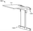
图1示出高度可调整壁安装组件的示例。Figure 1 shows an example of a height adjustable wall mount assembly.
图2示出提升件的正视图。Figure 2 shows a front view of the lift.
图3示出支撑托架的一个示例的横截面。Figure 3 shows a cross-section of an example of a support bracket.
图4示出图1的壁安装组件的透视图,包含图3的支撑托架。FIG. 4 shows a perspective view of the wall mount assembly of FIG. 1 , including the support bracket of FIG. 3 .
图5示出壁安装组件的详细透视图。Figure 5 shows a detailed perspective view of the wall mount assembly.
图6示出支撑托架的另一透视图。Figure 6 shows another perspective view of the support bracket.
图7示出锁释放组件和图3的支撑托架的透视图。FIG. 7 shows a perspective view of the lock release assembly and the support bracket of FIG. 3 .
图8示出倾翻式工作站的透视图。Figure 8 shows a perspective view of a tilting workstation.
图9示出图8的倾翻式工作站的详细透视图。FIG. 9 shows a detailed perspective view of the tilting workstation of FIG. 8 .
图10示出图8的倾翻式工作站的详细透视图,其中锁定组件处于解锁配置中。Figure 10 shows a detailed perspective view of the tilting workstation of Figure 8 with the locking assembly in the unlocked configuration.
图11示出图8的倾翻式工作站的透视图,其中锁定组件处于锁定配置中。11 shows a perspective view of the tilting workstation of FIG. 8 with the locking assembly in the locked configuration.
图12示出图8的倾翻式工作站的详细透视图,其中锁定组件处于解锁配置中。Figure 12 shows a detailed perspective view of the tilting workstation of Figure 8 with the locking assembly in the unlocked configuration.
图13示出图1的包含附接系统的高度可调整壁安装组件的透视图。13 shows a perspective view of the height adjustable wall mount assembly of FIG. 1 including the attachment system.
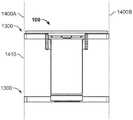
图14示出包含图13的附接系统的壁安装组件的正视图。FIG. 14 shows a front view of a wall mount assembly incorporating the attachment system of FIG. 13 .
图15示出图1的包含图13的附接系统的高度可调整壁安装组件的另一透视图。15 shows another perspective view of the height adjustable wall mount assembly of FIG. 1 incorporating the attachment system of FIG. 13 .
图16A到16C示出交接部组件的详细透视图。16A to 16C show detailed perspective views of the interface assembly.
图17A到17C示出附接机构的透视图。17A to 17C show perspective views of the attachment mechanism.
图18A到18B示出图17A到17C的附接机构的额外透视图。Figures 18A-18B show additional perspective views of the attachment mechanism of Figures 17A-17C.
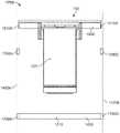
图19示出在安装操作期间图1的壁安装组件和图13的附接系统的正视图。Figure 19 shows a front view of the wall mount assembly of Figure 1 and the attachment system of Figure 13 during an installation operation.
图20示出包含高度调整机构的键盘托盘的示例的透视图。20 shows a perspective view of an example of a keyboard tray incorporating a height adjustment mechanism.
图21示出图20的键盘托盘的正视图。FIG. 21 shows a front view of the keyboard tray of FIG. 20 .
图22示出图20的键盘托盘的详细透视图。FIG. 22 shows a detailed perspective view of the keyboard tray of FIG. 20 .
图23示出图20的键盘托盘的另一详细透视图。FIG. 23 shows another detailed perspective view of the keyboard tray of FIG. 20 .
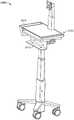
图24示出移动工作站的示例的侧视图。Figure 24 shows a side view of an example of a mobile workstation.
图25示出显示器安装组件的透视图。Figure 25 shows a perspective view of a display mount assembly.
图26示出显示器安装组件的另一透视图。Figure 26 shows another perspective view of the display mount assembly.
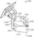
图27示出呈扩展配置的显示器臂组件的透视图。Figure 27 shows a perspective view of the monitor arm assembly in an expanded configuration.
图28示出呈收缩配置的显示器臂组件的透视图。Figure 28 shows a perspective view of the monitor arm assembly in a collapsed configuration.
图29A到29C示出呈偏移配置的显示器臂组件的透视俯视图。29A-29C show perspective top views of a monitor arm assembly in an offset configuration.
图30示出键盘托盘的一个示例的透视图。Figure 30 shows a perspective view of one example of a keyboard tray.
图31示出附接托架的详细视图。Figure 31 shows a detailed view of the attachment bracket.
图32A到32B示出呈扩展配置和收缩配置的键盘托盘的俯视图。32A-32B show top views of the keyboard tray in expanded and collapsed configurations.
图33A到33B示出呈旋转配置的键盘托盘的俯视图。33A-33B show top views of the keyboard tray in a rotated configuration.
图34A到34B示出可视需要包含计算机存储隔室的头部单元的示例的透视图。34A-34B show perspective views of examples of head units that may optionally include a computer storage compartment.
图35示出图24的可视需要包含一个或多个线缆出入孔的移动推车的示例的透视图。35 shows a perspective view of an example of the mobile cart of FIG. 24 optionally including one or more cable access holes.
图36示出头部单元的透视图。Figure 36 shows a perspective view of the head unit.
图37A到37B示出移动工作站的带轮基座的透视图。37A-37B show perspective views of the wheeled base of the mobile workstation.
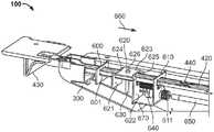
图38示出移动工作站的另一示例的透视图。Figure 38 shows a perspective view of another example of a mobile workstation.
图39示出附件保持器的示例的透视图。39 shows a perspective view of an example of an accessory holder.
图40示出带的示例的透视图。Figure 40 shows a perspective view of an example of a belt.
图41示出包含工作面的头部单元的透视图。Figure 41 shows a perspective view of the head unit including the work surface.
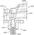
图42示出头部单元的另一透视图。Figure 42 shows another perspective view of the head unit.
图43示出头部单元的又一透视图。Figure 43 shows yet another perspective view of the head unit.
图44示出工作面打开机构和滑动件的透视图。Figure 44 shows a perspective view of the face opening mechanism and slide.
图45示出滑动件的详细透视图。Figure 45 shows a detailed perspective view of the slider.
图46示出工作面打开机构和滑动件的另一透视图。Figure 46 shows another perspective view of the face opening mechanism and slide.
图47示出工作面打开机构和滑动件的又一透视图。Figure 47 shows yet another perspective view of the face opening mechanism and slide.
图48示出工作面打开机构的示例的详细透视图。Figure 48 shows a detailed perspective view of an example of a face opening mechanism.
图49示出滑动件的另一透视图。Figure 49 shows another perspective view of the slider.
图50示出滑动件的又一透视图。Figure 50 shows yet another perspective view of the slider.
图51示出移动工作站2400的正视图。FIG. 51 shows a front view of the
图52示出头部单元和工作面的详细侧视图。Figure 52 shows a detailed side view of the head unit and work surface.
图53示出头部单元、滑动件和工作面打开机构的侧视图。Figure 53 shows a side view of the head unit, slide and work surface opening mechanism.
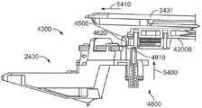
图54示出头部单元、滑动件和工作面打开机构的另一侧视图。Figure 54 shows another side view of the head unit, slide and work surface opening mechanism.
图55示出工作面打开机构和滑动件的侧视图。Figure 55 shows a side view of the face opening mechanism and slide.
具体实施方式Detailed ways
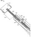
图1示出高度可调整壁安装组件100的示例。在一些示例中,工作面110可包含在壁安装组件100中。高度可调整壁安装组件100可包含固定提升件120和滑动托架130。固定提升件120可固定地附接到墙壁等结构。固定提升件120可具有宽度、在竖直方向上延伸的高度以及深度。滑动托架130可与固定提升件120以滑动方式接合。滑动托架130可相对于固定提升件120的一部分——例如固定提升件120的框架140——平移。FIG. 1 shows an example of a height adjustable
图2示出提升件120的正视图。高度调整机构200可连接在固定提升件120与滑动托架130之间以针对工作站100提供高度调整。高度调整机构200还可包含锁定组件210。锁定机构可通过固定高度调整机构200将工作面110维持在期望高度。FIG. 2 shows a front view of
框架140可限定一个或多个安装特征,例如安装孔220。安装特征可适于帮助将提升件120与支撑结构(例如墙壁、隔间壁、独立框架等等)联接(例如,附连、附接等等)。框架140可适于容纳以及以其它方式支撑壁安装组件100的部件。
滑动托架130可适于联接并由此支撑壁安装组件100的部件,例如工作面110。滑动托架130可与框架140以可移动方式联接,使得滑动托架130适于相对于框架140平移。滑动托架130的一部分可与框架140的一部分接合,由此将滑动托架130与框架140以可移动方式联接。在示例中,框架140限定键槽,而滑动托架130包含键。键槽的大小和形状可设定成接收键。键的大小和形状可设定成与键槽接合。键与键槽的接合可有助于将滑动托架130与框架140以可移动方式联接。
如本公开中所描述,滑动托架130可相对于框架140平移,例如,线性平移,这可改变滑动托架130(以及附接到滑动托架130的部件,例如工作面110)的高度。As described in this disclosure, sliding
提升件120可包含配衡机构230,并且配衡机构230可包含在高度调整机构200中。配衡机构230可包含一个或多个弹簧231。配衡机构230可包含轮线缆232(例如,抗拉构件)。轮线缆232的一端可联接到滑动托架130,而轮线缆232的另一端可联接到一个或多个弹簧231。配衡机构230可包含轮/凸轮组件233。轮线缆232可与轮/凸轮组件233的一部分接合。另外,轮线缆232可与滑轮234接合。Lift 120 may include a
在另一示例中,配衡机构230可包含多个轮线缆232。例如,第一轮线缆232的一端可联接到滑动托架130,而第一轮线缆232的另一端可联接到轮/凸轮组件233。第二轮线缆232可联接于轮/凸轮组件233与一个或多个弹簧231之间。In another example, the
再次参考图2,弹簧231、轮线缆232和轮/凸轮组件233可协作以帮助配衡施加到滑动托架130的力。配衡施加到滑动托架130的力可有助于维持相对于框架140平移滑动托架130所需的力的量。换句话说,配衡机构230可适于支撑滑动托架130,使得即使在平移期间由弹簧231产生的力增大,相对于框架140平移滑动托架130所必要的力的量也保持基本恒定。另外,配衡机构230可有助于例如通过提供等同于滑动托架130和与其连接的所有部件--包含(但不限于)工作面110(图1中所示)--的组合重量的提升力来维持滑动托架130相对于框架140的位置。Referring again to FIG. 2 ,
在示例中,滑动托架130联接到配衡机构230和工作面110(图1中所示)。例如,使用者可将十五磅物体放置在工作面110上,而配衡机构230可帮助维持滑动托架130(以及由此工作面110)相对于使用者的位置(例如,高度)。此外,如果使用者希望改变(例如,升高或降低)工作面110的位置,配衡机构230会帮助维持改变滑动托架130(以及由此工作面110)的位置所必要的力的量,使得不管十五磅负荷是否施加于工作面110,相对于框架140改变滑动托架130的位置所必要的力的量基本上相同。In an example,
再次参考图2,壁安装组件100可包含锁杆240。锁杆240可联接到框架140。尽管锁杆240可定位在框架140内部或外部,但图2中描绘的具体配置描绘了定位在框架140外侧的锁杆240。锁杆240可与框架140间隔开第一距离(例如,锁杆240与框架140之间可存在间隙)。锁杆240可具有圆形、正方形、矩形、其它几何形状或不规则横截面(例如,锁杆240可限定键槽)。Referring again to FIG. 2 , the
如本公开中所描述,壁安装组件100可包含锁定组件210。锁定组件210的大小和形状可设定成接收锁杆240。锁定组件210可适于选择性地相对于(例如沿着)锁杆240平移。锁定组件210可联接到滑动托架130或包含在所述滑动托架中。锁定组件210可有助于维持滑动托架130相对于框架140的位置。锁定组件210可联接到工作面110(图1中所示)。锁定组件210可适于与工作面110联接,例如间接地通过滑动托架130或直接联接到工作面110。锁定组件210可有助于维持工作面110相对于提升件120(或框架140)的位置。在示例中,锁定组件210可相对于锁杆240在第一方向上(例如,竖直地)平移。锁定组件210在第一方向上的平移可相应地引起工作面110在第一方向上平移。
图3示出支撑托架300的一个示例的正视图。为了清楚起见,可移除支撑托架300的部分。一个或多个支撑托架300可包含在壁安装组件100(图1中所示)中。例如,支撑托架300可联接到滑动托架130(图1中所示)。在一些示例中,支撑托架300包含U形横截面。支撑托架300可包含第一侧310、与第一侧310相对的第二侧320以及连接第一侧310和第二侧310、320的下端的第三侧330。第一侧310和第二侧320的高度可随着横截面接近支撑托架300的后端而增大,在所述后端处,支撑托架300可联接到滑动托架130以为工作面110提供额外结构支撑。第一凸缘340和第二凸缘350可分别形成于第一侧310和第二侧320的上端处。工作面110可通过位于第一凸缘340和第二凸缘350上的一个或多个孔口附接到支撑托架300(例如,一个或多个紧固件可延伸穿过所述孔口以将工作面110和支撑托架300联接)。FIG. 3 shows a front view of one example of a
图4示出图1的壁安装组件100的透视图,包含图3的支撑托架300。锁释放组件400可以操作方式连接到工作面110(图1中所示)。锁释放组件400可用于选择性地释放锁定机构210以调整工作面110的高度。锁释放组件400可部分地位于支撑托架300内部,例如,如图4中所示。锁释放组件400可包含固定柄部托架410和细长构件420。在一些示例中,固定柄部托架410可附接到工作面110(图1中所示)的下侧。柄部430可连接到细长构件420的第一端421。在一些示例中,柄部430可与固定柄部托架410以滑动方式接合。柄部430可位于距支撑托架300第一距离450处。FIG. 4 shows a perspective view of the
另外,细长构件420的第二端422可延伸到支撑托架300中。如本文中更详细描述,细长构件420可包含沿着细长构件420的长度的一个或多个连接孔440。一个或多个连接孔440可促进相对于支撑托架300重新定位柄部430。例如,连接孔440可促进将柄部430重新定位在距支撑托架300第二距离(例如,图7中示出的第二距离700)处。Additionally, the
图5示出壁安装组件100的详细透视图。如本文件中所描述,柄部430可与固定柄部托架410以滑动方式接合。在示例中,固定柄部托架410可包含凹槽500,并且柄部430的大小和形状可设定成接收凹槽500(例如,滑动柄部430可限定大小和形状可设定成接收凹槽500的通道)。FIG. 5 shows a detailed perspective view of the
图6示出支撑托架300的另一透视图。支撑托架300的一部分被隐藏以示出支撑托架300的内部部件。第一导引托架600和第二导引托架610可与支撑托架300联接,并且第一导引托架600可与第二导引托架610间隔开。第一导引托架600和第二导引托架610可分别限定第一孔口601和第二孔口611。细长构件420可穿过第一孔口601和第二孔口611。例如,细长构件420可与第一孔口601和第二孔口611以可滑动方式接合。第一孔口601和第二孔口611可在细长构件420相对于支撑托架300的平移期间为细长构件420提供导引。FIG. 6 shows another perspective view of the
连接托架620可固定地附接到细长构件420。连接托架620可包含第一面621、第二面622和第三面623。第一面621可与第二面622平行,并且第三面623可连接第一面621与第二面622。第一面621可限定第三孔口624,而第二面622可限定第四孔口625。细长构件420可穿过第三孔口624和第四孔口625。连接构件630的第三面623可限定孔626。紧固件630可插入穿过孔626,并且紧固件630可与细长构件420接合。例如,紧固件630(例如螺杆、销等等)可与一个或多个连接孔440接合以将连接构件620与细长构件420联接。在一些示例中,连接构件620可位于第一导引托架600与第二导引托架610之间。
锁释放组件400还可包含偏置构件640(例如弹簧)。偏置构件640可位于第二导引托架610与连接托架620的第二面622之间。偏置构件640可联接到导引托架610和连接托架620,并且偏置构件640可使连接托架620在第一方向上(例如,如图6所示的箭头660标示)偏置。连接托架620可与止动件670接合,并且止动件670可抑制连接托架620相对于支撑托架300的移动。在示例中,止动件670可包含在第二导引托架610中。在另一示例中,止动件670可与支撑托架300的一部分联接。使用者可操作(例如,牵拉、扭转、推动等等)柄部430,而对柄部430的操作可使连接托架620在与第一方向相反的第二方向上(例如,沿着细长构件420的长度轴线)移位。连接托架620的移位可使偏置构件640移位,并且当柄部430被释放时,偏置构件640可使连接托架620在第一方向上偏置以与止动件670接合。The
再次参考图6,锁释放组件400可包含锁释放线缆650。锁释放线缆650可与连接托架620(例如第二面622)以及与锁定机构210(图2中所示)联接。如本文所描述,使用者可操作柄部430,并且使连接构件620例如在第二方向上移位。连接托架620可相应地使锁释放线缆650移位,而锁释放线缆650的移位可操作锁定机构210并且促进工作面110的高度调整。Referring again to FIG. 6 , the
如本文件中所描述,柄部430可相对于支撑托架300重新定位。在示例中,壁安装组件100可适应具有不同尺寸(例如,不同深度)的工作面110。相对于支撑托架300重新定位柄部420可允许柄部430安装在工作面110的前边缘附近,例如以便于使用者轻松接近柄部430。The
图7示出锁释放组件400和图3的支撑托架300的透视图。如本文件中所描述,柄部430(和固定柄部托架410)可位于距支撑托架300第一距离450(图4中所示)处。在另一示例中,柄部430可位于距支撑托架300第二距离700处。重新定位柄部430可促进将柄部430定位在工作面110的前边缘附近。第二距离700可大于第一距离450(图4中所示)。FIG. 7 shows a perspective view of the
可在使第一导引托架600、第二导引托架610和连接托架620相对于支撑托架300保持在相同位置的同时实现对柄部430重新定位。在示例中,柄部460可通过使紧固件630与一个或多个连接孔440脱离而重新定位。使紧固件630与连接孔440脱离可允许细长构件420相对于连接托架630平移。使细长构件420相对于连接托架630平移可改变柄部430与支撑托架300之间的距离(例如,在第一距离450与第二距离700之间)。紧固件630可插入穿过连接托架620,并且与连接孔440接合。紧固件630与连接孔440的接合可抑制细长构件420相对于连接托架620的平移。因此,当紧固件430与连接托架430和连接孔440接合时,柄部430可被操作以使锁释放线缆(图6中所示)移位并操作锁定组件210(图2中所示)。Repositioning of the
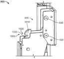
图8示出倾翻式工作站800的透视图。倾翻式工作站800可包含高度可调整壁安装组件100。附接托架810可联接到滑动托架130。附接托架810可包含铰链820,并且支撑托架300可联接到附接托架810。在示例中,支撑托架300可围绕铰链820旋转,并且支撑托架300的旋转可允许工作面110在水平位置与竖直位置之间转变。钩销830可与附接托架810联接。FIG. 8 shows a perspective view of a tilting
图9示出图8的倾翻式工作站800的详细透视图。工作站800可包含锁定组件900,并且锁定组件900可包含钩销830。钩销830可在附接托架810的侧面之间延伸。在一些示例中,钩销830可位于附接托架810的上端附近。另外,铰链820可在附接托架810的侧面之间延伸,并且铰链820可位于附接托架810的下端附近。此外,铰链820可与钩销830间隔开。FIG. 9 shows a detailed perspective view of the tilting
图10示出图8的倾翻式工作站800的详细透视图,其中锁定组件900处于解锁配置中。锁定组件900可包含闩锁定组件1000,并且闩锁定组件1000可包含第一臂1010。第一臂1010可限定销通道1020,并且销通道1020的大小和形状可设定成接收钩销830。当钩销830未被收在销通道1020内时,锁定组件900可处于解锁配置中。另外,锁定组件900可包含锁定配置,并且当钩销830被收在销通道1020内时,锁定组件900可处于锁定配置中。将钩销830收在销通道1020内可防止支撑托架300围绕铰链820旋转。例如,钩销830可与销通道1020的通道壁1030接合,并且所述接合可将工作面110(图8中所示)维持在水平位置。FIG. 10 shows a detailed perspective view of the
图11示出图8的倾翻式工作站800的透视图,其中锁定组件900处于锁定配置中。为清楚起见,已从图11移除倾翻式工作站800的部分。例如,为了清楚起见,图9中所示的工作面110以及支撑托架300的侧面已从图11移除。如图11中所示,钩销830被收在销通道1020内。因此,支撑臂300位于水平位置。FIG. 11 shows a perspective view of the
如本文件中所描述,闩锁组件1000可包含第一臂1010。另外,闩锁组件1000可包含与第一臂1010联接的第二臂1100。例如,第一臂1010可与第二臂1100通过臂铰链1110以旋转方式联接。臂铰链1110可与支撑托架300联接,并且臂1010、1100可相对于支撑托架300旋转。在另一示例中,第一臂1010和第二臂1100可形成为单个部件的组成部分,并且臂1010、1100可围绕臂铰链1110旋转。The
闩锁组件1000可包含闩锁操作件1120,而对闩锁操作件1120的操控可使臂1010、1100相对于支撑托架300移位。例如,操作件1120可与闩锁条1130联接,并且闩锁条1130可相对于支撑托架300平移(例如,当闩锁操作件1120被使用者操控时,闩锁条1130可在支撑件300内滑动)。闩锁条1130可包含卡扣1140,并且卡扣1140可与臂1110接合以使臂1010移位。在此示例中,因为臂1010、1100联接在一起,所以臂1100的移位会相应地使臂1010移位(例如,当臂1100移位时,臂1010、1100围绕臂铰链1110旋转)。如本文件中更详细地描述,臂1010、1100的移位可使钩销830与销通道1030脱离,并且允许锁定组件900从锁定配置转变到解锁配置。The
图12示出图8的倾翻式工作站800的详细透视图,其中锁定组件900处于解锁配置中。闩锁组件1000可包含偏置构件1200,并且偏置构件1200可使第一臂1010朝着与锁定销830的接合而偏置。如本文中所描述,销通道1020可接收钩销830。在示例中,偏置构件1200可使臂1010偏置以将钩销830维持在销通道1020内。对闩锁操作件1120的操控可克服偏置构件1200的偏置,并且允许钩销830与销通道1030脱离。FIG. 12 shows a detailed perspective view of the
另外,臂1010可包含凸轮表面1210,并且凸轮表面1210可配置成与钩销830接合。凸轮表面1210与钩销830的接合可使臂1010移位,并且允许钩销830收在销通道1020中。在示例中,工作面110可从竖直(例如,存储)位置转变到水平(例如,工作)位置。凸轮表面1210可允许锁定组件900在工作面110(图1中所示)升高到水平位置时转变到锁定配置。钩销830可在工作面升高时与凸轮表面1210接合,并且与销通道1020对准。偏置构件1020可使臂1010朝着与钩销830的接合而偏置,并且钩销830可被收在销通道1020中。因此,凸轮表面1210可允许锁定组件800在工作面110升高时转变成锁定配置。Additionally,
图13示出图1的包含附接系统1300的高度可调整壁安装组件100的透视图。如本文件中所描述,高度可调整壁安装组件100可直接附接到结构(例如,墙壁)。在另一示例中,壁安装组件100可通过附接系统1300附接到结构(例如,墙壁、壁板、隔间壁等)。如本文件中更详细地论述,附接系统1300可允许壁安装组件100与具有不同尺寸或特性的结构联接。FIG. 13 shows a perspective view of height adjustable
图14示出包含图13的附接系统1300的壁安装组件100的正视图。如本文件中所描述,附接系统1300可允许壁安装组件100与具有不同尺寸或特性的结构联接。在示例中,所述结构可包含包含多个狭槽1410的带槽托架1400A、1400B,并且所述多个狭槽1410可串联布置(例如,间隔开并且布置成列)。附接系统1300可与狭槽1410接合并且允许安装组件100与所述结构联接。FIG. 14 shows a front view of
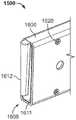
图15示出图1的包含附接系统1300的高度可调整壁安装组件100的另一透视图。在示例中,附接系统1300可包含第一交接部组件1500和第二交接部组件1510。交接部组件1500、1510可在第一侧联接到结构。另外,交接部组件1500、1510可在第二侧联接到提升件120,以将安装组件100联接到结构。在示例中,提升件120可包含第一接合托架1520、第二接合托架1530和第三接合托架1540。接合托架1520、1530、1540的大小和形状可设定成接收交接部组件1500、1510,并且接合托架1520、1530、1540对交接部组件1500、1510的接收可使提升件120与交接部组件1500、1510联接。FIG. 15 shows another perspective view of height adjustable
图16A到16C示出交接部组件1500的详细透视图。交接部组件1500可包含细长支撑构件1600和插入件1610。支撑构件1600的大小和形状可设定成接收插入件1610,并且插入件1610可位于支撑构件1600的一端1605中。插入件1610的外部轮廓可至少部分地与支撑构件1600的内部轮廓对应。插入件1610可位于支撑构件1600中,并且一个或多个紧固件1620可用于将插入件1610与支撑构件1600联接。16A-16C show detailed perspective views of the
插入件1610可包含插入件主体1611和键1612(例如,圆锥、突出部等等)。键1612可从插入件主体1611延伸。键1612可从键1612的第一端到第二端稍微逐渐变细。在键1612中可限定螺纹孔1613,并且螺纹孔1613可接收紧固件以将插入件与附接系统1300的其它部件联接。Insert 1610 may include an
图17A到17C示出附接机构1700的透视图。附接机构1700可包含在交接部组件1500中。附接机构1700可与带槽托架1400A、1400B(图14中所示)联接。例如,附接机构1700可包含具有第一钩突出部1720的第一凸台1710,以及具有第二钩突出部1740的第二凸台1730。钩突出部1720、1740可被收在狭槽1410中,并且将钩突出部1720、1740收在狭槽1410中可使附接机构1700与带槽托架1400A、1400B联接。17A-17C show perspective views of
如图17A和17C所示,第一钩突出部1720可在第一方向上取向,并且第二钩突出部1740可在第二方向上取向。例如,第一钩突出部1720可包含在第一方向上(例如,向下)开放的第一通道1721。第二钩突出部1740可包含在第二方向上(例如,向上)开放的第二通道1741。As shown in Figures 17A and 17C, the
凸台1710、1730可与附接主体1750联接。凸台1710、1730中的一个或多个凸台可相对于附接主体1750平移,以例如将附接机构1700与带槽托架1400A、1400B(图14中所示)联接。在示例中,螺母1760可位于附接主体1750中并且位于凸台1710的第一法兰1711附近。螺栓1770可插入穿过凸台1730的第二法兰1731,并且螺栓1770可与螺母1760接合。使用者可操控(例如,转动、扭转、驱动等等)螺栓1770,而对螺栓1770的操控可使凸台1720相对于附接主体1750平移。
如本文件中所描述,附接机构1700可与带槽托架1400A、1400B(图14中所示)联接。在示例中,附接机构可钳夹到带槽托架1400A、1400B。钩突出部1720、1740可位于狭槽1410(图14中所示)中,并且第二凸台1730可相对于附接主体1750平移以缩小凸台1710、1730之间(以及因此钩部分1720、1740之间)的距离。
再次参考图17A到17C,附接主体1750可限定键槽1780。键槽1780的大小和形状可设定成接收插入件1610的键1612(图16A到16C中所示)。键1612与键槽1780的接合可使插入件1610与附接机构1700配合。键槽1780可具有对应于键1612的键轮廓的键槽轮廓。在示例中,键槽1780可渐缩以对应于键1612的渐缩轮廓。Referring again to FIGS. 17A-17C , the
可在附接主体1750中限定第一通孔1790A。第一通孔1790A可允许接近螺栓1770,并且允许使用者操控螺栓1770并使凸台1710、1730相对于附接主体平移。另外,可在附接主体1750中限定第二通孔1790B。紧固件(例如,螺杆)可插入到通孔1790B中以使插入件1610(图16A到16C中所示)与附接机构1700联接。在示例中,紧固件可与插入件1610的螺纹孔1613接合,而紧固件与插入件1610的接合可使插入件1610与附接机构1750联接(例如,防止键1612在键槽1780内平移)。A first through
图18A到18B示出图17A到17C的附接机构1700的额外透视图。如本文件中所描述,凸台1730可相对于附接主体1750(以及凸台1710)平移。在示例中,并且如图18A中所示,凸台1730可被平移成与凸台1710邻接。在另一示例中,凸台1730可被平移成远离凸台1710,例如以允许附接机构1700插入到狭槽1410(图14中所示)中。凸台1730可被平移(例如,通过操控图17中所示的螺栓1770)成邻接凸台1710,例如以将附接机构1700联接(例如,钳夹)到带槽托架1400A、1400B。18A-18B show additional perspective views of the
图19示出在安装操作期间图1的壁安装组件100和图13的附接系统1300的正视图。如本文中所描述,附接机构1700可与带槽托架1400A、1400B联接。在示例中,多个附接机构1700可联接到带槽托架1400A、1400B。例如,第一附接机构1700A和第二附接机构1700B可联接到带槽托架1400A。第三附接机构1700C和第四附接机构1700D可与带槽托架1400B联接。FIG. 19 shows a front view of the
如本文件中所描述,交接部组件1500、1510可包含支撑构件1600。另外,插入件1610可与支撑构件1600联接。在示例中,第一插入件1610A和第二插入件1610B可与支撑构件1600联接。交接部组件1510的支撑构件1600可通过将插入件1610A、1610B与附接机构1700B、1700D联接来与附接机构1700B、1700D联接。此外,交接部组件1500的支撑构件1600可通过将插入件1610A、1610B与附接机构1700A、1700C联接来与附接机构1700A、1700C联接。支撑构件1600可具有可调整长度(例如,支撑构件1600可包含允许可变长度的伸缩区段)。因此,在各结构当中带槽托架1400A、1400B之间的距离改变(例如第一立方壁在托架1400A、1400B之间具有第一距离,而第二立方壁在托架1400A、1400B之间具有第二距离)的情况下,支撑构件1600可跨越附接机构1700A、1700C之间的距离。
交接部组件1500的支撑构件1600可与提升件120的第一托架1530(图15中所示)接合(例如,收在其中)。另外,交接部组件1510的支撑构件1600可与接合托架1540、1550(图15中所示)接合。因此,并且如图14所示,提升件120可通过附接系统1300联接到带槽托架1400A、1400B。The
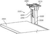
图20示出包含高度调整机构2010的键盘托盘2000的示例的透视图。一个或多个悬挂组件2020可连接到工作面(例如,图1中所示的工作面110)的下侧。如图20所示,键盘托盘2000可联接到悬挂组件2020。FIG. 20 shows a perspective view of an example of a
图21示出图20的键盘托盘2000的正视图。在示例中,两个悬挂组件2020可连接到工作面110。第一悬挂组件2020A和第二悬挂组件2020B可具有类似构造(例如,组件2020A、2020B可以是彼此的镜像)。FIG. 21 shows a front view of the
图22示出图20的键盘托盘2000的详细透视图。悬挂组件2020可包含第一安装托架2200和第二安装托架2210。安装托架2200、2210可保持第一悬挂托架2220的一端,并且可连接到工作面110(图21中所示)的下侧。第一悬挂托架2220可形成为中空横截面,并且第二悬挂托架2230可位于第一悬挂托架2220的中空横截面中。第二悬挂托架2230可与第一悬挂托架2220以可滑动方式接合,并且托架2230可相对于托架2220平移。第一悬挂托架2220还可包含连接到第一悬挂托架2220的一侧的带槽托架2240。一个或多个狭槽2250可形成于带槽托架2240上。键盘托盘2000可连接到第二悬挂托架2230。因此,键盘托盘2000可相对于托架2220平移。FIG. 22 shows a detailed perspective view of the
图23示出图20的键盘托盘2000的另一详细透视图。为了清楚起见,已隐藏悬挂组件2020的部分。第二悬挂托架2230可包含中空区段2300,并且钩臂2310可位于第二悬挂托架2230的中空区段2300内部。钩臂2310可例如在铰链2320处与第二悬挂托架2230以旋转方式联接。钩臂2310可包含钩2340,并且钩2340可与带槽托架2240接合以维持第二悬挂托架2230相对于第一悬挂托架2220的位置。柄部2350可以旋转方式联接到第二悬挂托架2230,并且对柄部2350的操控可使钩臂2310围绕铰链2320旋转。柄部2350可固定地附接到钩臂2310,因此柄部2350和钩臂2310可联合围绕铰链2320旋转。FIG. 23 shows another detailed perspective view of the
如本文件中所描述,第二悬挂托架2230可与第一悬挂托架2220以滑动方式接合。第二悬挂托架2230可相对于第一悬挂托架2220重新定位,并且钩2340与带槽托架2240的接合可维持第二悬挂托架2230的位置。在示例中,钩2340可被收在狭槽2250中以维持托架2230相对于托架2220的位置。The
偏置构件2360可包含在悬挂组件2020中,并且偏置构件2360可维持钩2340与狭槽2250的接合。在示例中,扭转弹簧可位于铰链2320的轴线处。扭转弹簧可使钩臂2310在逆时针方向偏置,使得钩2340可始终与一个或多个狭槽2250中的个别狭槽接合。在此示例中,当柄部2350围绕铰链2320旋转时,钩臂2310可与柄部2350一起在顺时针方向上旋转,并且钩2340可与所述个别狭槽脱离。因此,第二悬挂托架2230可相对于第一悬挂托架2220平移。A biasing
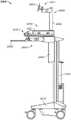
图24示出移动工作站2400的示例的侧视图。移动工作站2400可包含带轮基座2410和连接到带轮基座2410的提升件2420。提升件2420可类似于图1所示的提升件120。例如,滑动托架(例如,图1所示的滑动托架130)可与提升件2420接合以可滑动方式接合。头部单元组件2430和线缆存储盒2440可连接到滑动托架。另外,配衡机构(例如,图2中所示的配衡机构230)可连接到提升件2420并且可联接到滑动托架。如本文中所描述,配衡机构可为滑动托架提供高度调整。通过使滑动托架相对于提升件2420的一部分平移,可选择性地调整带轮基座2410与头部单元2430和线缆存储盒2440之间的距离。FIG. 24 shows a side view of an example of a
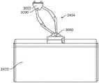
头部单元组件2430可包含工作面2431和计算机存储隔室2432,举例来说,存储隔室2432可位于工作面2431下方。另外,键盘托盘2433可位于计算机存储隔室2432下方。键盘托盘臂组件2434可连接到头部单元组件2430,并且连接到键盘托盘2433。键盘托盘臂组件2434可为键盘托盘2433提供相对于工作面2431的一些铰接。The
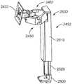
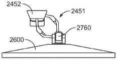
显示器安装组件2450可联接到移动工作站2400,例如,显示器安装组件2450可位于工作面2431上方。显示器安装件2453可通过显示器臂组件2451和显示器安装提升件2452连接到头部单元2430。显示器安装提升件2452可联接到头部单元2430,例如在工作面2431上方。显示器臂组件2451可联接到显示器安装提升件2452和显示器安装件2453。显示器臂组件2451可为显示器安装件2453提供相对于显示器安装提升件2452的铰接。显示器(例如,图26中所示的显示器2600)可附接到显示器安装件2453以将显示器定位在工作面2431上方。在一些示例中,显示器安装提升件2452可为显示器提供相对于工作面2431的高度调整。A
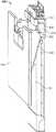
图25示出显示器安装组件2450的透视图。如本文件中所描述,显示器安装提升件2452可连接到头部单元2430(图24中所示)以将显示器保持在工作面2431上方。显示器安装提升件2452可包含安装块2500、第一构件2510以及可与第一构件2510以可滑动方式联接的第二构件2520。第二构件2520可联接到安装块2500,而安装块可联接到头部单元2430。配衡机构(例如,类似于图2中所示的配衡机构230的配衡机构)可联接到第二构件2520和第一构件2510,以选择性地调整显示器安装件与工作面2431(图24中所示)的距离。在一些示例中,显示器臂组件2451可连接到显示器安装提升件2452的上端2530。FIG. 25 shows a perspective view of
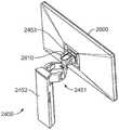
图26示出显示器安装组件2450的另一透视图。显示器2600(例如,监视器、电视、屏幕等等)可联接到显示器安装件2453。可通过铰接显示器臂组件2451来调整显示器2600相对于显示器安装提升件2452的位置。显示器安装件2453还可包含倾翻式托架2610,用以调整显示器2600相对于显示器安装提升件2452的角度。FIG. 26 shows another perspective view of the
图27示出呈扩展配置的显示器臂组件2451的透视图。显示器臂组件2451可包含第一臂2700、第二臂2710、第三臂2720和第四臂2730。第一臂2700和第二臂2710可在第一铰链2740处以旋转方式联接。第二臂2710和第三臂2720可在第二铰链2750处以旋转方式联接。第三臂2720和第四臂2730可在第三铰链2760处以旋转方式联接。第四臂2730和第一臂2700可在第四铰链2770处以旋转方式彼此联接。铰链2740、2750、2760、2770的旋转轴线2780可彼此平行。旋转轴线2780可平行于显示器安装提升件2452(图24中所示)中的高度调整的运动方向。显示器臂组件2451可在第一铰链2740处连接到显示器安装提升件2452。因此,第一臂2700和第二臂2710可在第一铰链2740处以可旋转方式联接到显示器安装提升件2452。显示器安装件2453可在第三铰链2760处连接到显示器臂组件。因此,第三臂2720和第四臂2730可在第三铰链2760处以可旋转方式联接到显示器安装件2453。Figure 27 shows a perspective view of the
图28示出呈收缩配置的显示器臂组件2451的透视图。显示器臂组件2451可进行铰接以允许显示器安装件2453与显示器安装提升件2452之间的距离改变。如图28中所示,显示器安装件2453接近显示器安装提升件2452定位。如图27中所示,显示器安装件2453可远离显示器安装提升件2452定位。Figure 28 shows a perspective view of the
再次参考图28,第一臂2700和第二臂2710可围绕第一铰链2740旋转,并且因此第二铰链2710和第四铰链2730可移动远离彼此。分别在第二铰链2750和第四铰链2760处联接到第一臂2700和第二臂2710的第三臂2720和第四臂2730也可相对于彼此旋转。因此,如图28中所示,第三铰链2760可移动得更接近第一铰链2740。Referring again to FIG. 28, the
图29A到29C示出呈偏移配置的显示器臂组件2451的透视俯视图。显示器臂组件2451可允许显示器安装件2453相对于显示器安装提升件2452横向(例如向右或向左)移动。第一臂2700和第二臂2710可旋转(例如,在逆时针方向上),并且因此第三铰链2760可移动。显示器安装件2453可相对于显示器安装提升件2452横向(例如,向右)移动,例如如图29C中所示。另外,显示器安装件2453可围绕第三铰链2760旋转以使显示器2600相对于显示器臂组件旋转,例如以使显示器2600面向侧向方向。29A-29C show perspective top views of a
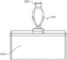
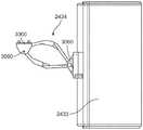
图30示出键盘托盘2433的一个示例的透视图。如本文件所描述,键盘托盘2433可在计算机存储隔室2432(图24中所示)下方连接到头部单元2430。附接托架3000可联接到头部单元2430,以将键盘托盘臂组件2434和键盘托盘2433联接到头部单元2430。保持块3010可联接在键盘托盘臂组件2434与键盘托盘2433之间。FIG. 30 shows a perspective view of one example of
键盘托盘臂组件2434可包含第一臂3020、第二臂3030、第三臂3040和第四臂3050。第一臂3020和第二臂3030可在第一铰链3060处以旋转方式联接。第一铰链可包含在保持块组件3010中,并且第一臂3020和第二臂3030可在第一铰链3060处以旋转方式联接到保持块3010。第一臂3020和第四臂3040可在第二铰链3070处以旋转方式联接。第二臂3030和第三臂3040可在第三铰链3080处以旋转方式联接。第四铰链3090可包含在附接托架3000中,并且第四铰链3090可延伸穿过附接托架3000。The keyboard
图31示出附接托架3000的详细视图。为清楚起见,已从图31移除附接托架3000的部分。附接托架3000可包含铰链保持托架3100。铰链保持托架3100可在第四铰链3090处与附接托架3000以旋转方式联接。FIG. 31 shows a detailed view of
第三臂3040可包含第一齿轮块3110,并且第四臂3050可包含第二齿轮块3120。第一齿轮块3110可在第五铰链3130处与铰链保持块3100以旋转方式联接,并且第二齿轮块3120可在第六铰链3140处与铰链保持块3100以旋转方式联接。铰链3060、3070、3080、3090、3130、3140的旋转轴线3150可彼此平行,并且旋转轴线3150可处于竖直取向。The
齿轮块3110、3120可各自包含多个齿3160,例如齿3160可包含在齿轮块3110、3120的外部表面上。齿轮块3110、3120上的齿3160可彼此啮合以使臂3040、3050围绕铰链3130、3140的旋转同步。所述同步可允许臂3040、3050以相同增量围绕铰链3130、3140旋转。The gear blocks 3110 , 3120 may each include a plurality of
图32A到32B示出呈扩展配置和收缩配置的键盘托盘2433的俯视图。键盘托盘臂组件2434可允许键盘托盘2433相对于附接托架3000铰接,并因此改变键盘托盘2433相对于附接托架3000的距离或取向。在示例中,并且如图32B所示,键盘托盘臂组件2434可被铰接以将键盘托盘2433定位在附接托架3000附近。将键盘托盘2433定位在附接托架3000附近可允许当键盘托盘2433不在使用中时将键盘托盘2433收到计算机存储隔室2432(图24中所示)下方。在另一示例中,并且如图32A所示,键盘托盘臂组件2434可被铰接以将键盘托盘2433远离附接托架3000定位。将键盘托盘2433远离附接托架3000定位可允许例如通过使用者将键盘托盘2433从计算机存储隔室2432下方拉出而使键盘托盘2433暴露。32A-32B show top views of the
图33A到33B示出呈旋转配置的键盘托盘2433的俯视图。键盘托盘臂组件2434可围绕第四铰链3090旋转,并且允许键盘托盘相对于附接托架3000横向(例如,向右或向左)移动。另外,键盘托盘2433可围绕第一铰链3060旋转以面对如图33A到33B所示的不同方向。33A-33B show top views of
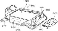
图34A到34B示出可视需要包含计算机存储隔室2432的头部单元2430的示例的透视图。如本文件中更详细地描述,计算机存储隔室2432可被工作面3431覆盖。另外,工作面2431可从头部单元2430移除。在头部单元2430中可包含控制面板3400,例如,控制面板3400可位于控制面板壳体3405中。控制面板壳体3405可位于计算机存储隔室2432附近。在示例中,显示器(例如,图26中示出的显示器2600)可包含在控制面板3400中。显示器可以是触敏式的,并且移动工作站2400的各种功能可利用显示器来控制。例如,显示器可控制移动工作站2400的高度调整、连接到移动工作站2400的计算机的互联网访问、一个或多个部件(例如,计算机、电池等)的功率监测警示等。34A-34B show perspective views of an example of a
头部单元2430可包含一个或多个柄部3410。在示例中,头部单元2430可限定柄部3410,并且柄部3410可位于计算机存储隔室2432附近。另外,头部单元2430可包含一个或多个附件搁架3420,例如搁架3420可接近于计算机存储隔室2432连接到头部单元3430。在另一示例中,控制面板壳体3405、柄部3410和附件搁架3420可由头部单元2430限定。在又一示例中,控制面板壳体3405、柄部3410和附件搁架3420可单独形成,随后附接到头部单元2430。
另外,头部单元2430可限定一个或多个凹部3440。凹部3440可用于将附件平台3450附接到头部单元2430。在示例中,一个或多个脊部3460可包含在附件平台3450中。脊部3460可与凹部3440接合以将附件平台附接到头部单元2430。此外,一个或多个凸台3470可包含在附件平台3450中。凸台3470可与头部单元2430接合以向头部单元2430与附件搁架3450之间的连接提供额外刚度。例如,螺杆可插入穿过头部单元2430以及凸台3470以与附件搁架3450接合并提供额外安全性以将附件搁架3450联接到头部单元2430。Additionally, the
附件平台3450可包含底部表面3451。附件平台3450的底部表面3451可以是平坦的,或具有各种形状以匹配要位于附件平台3450上的附件。附件平台3450的底部表面3451可具有一个或多个狭槽3452,以将附件(例如,消毒擦拭物容器、扫描仪保持器、打印机等)安装到附件平台。在一些示例配置中,紧固件(例如,螺杆)可插入穿过狭槽3452,并且紧固件可接合附件以将附件固定到附件平台3450。
图35示出图24的可视需要包含一个或多个线缆出入孔3500的移动推车2400的示例的透视图。头部单元2430可限定一个或多个线缆出入孔3500。线缆出入孔3500可允许从头部单元2430外部接近计算机存储隔室2432。在示例中,线缆出入孔3500可允许线缆存储盒2440或计算机存储隔室2432与位于附件搁架3420(或附件平台3450,图34A到34B中所示)上的附件之间的线缆敷设。在示例中,笔记本电脑的电源可位于计算机存储隔室2432中(或在附件搁架3420上)。第一电源线缆可从计算机存储隔室2432穿过线缆出入孔3500,并且与位于线缆存储盒2440中的第二电源线缆联接。FIG. 35 shows a perspective view of an example of the
图36示出头部单元2430的透视图。一个或多个光源3600可内置到头部单元以在环境光照不足以执行与移动工作站相关联的各种任务时提供额外光。第一光源3600A可在工作面2431上方附接到头部单元2430以照射位于工作面2431上的物体。第二光源3600B和第三光源可附接到附件搁架3420的下侧以在键盘托盘2433被移到头部单元2430的右侧或左侧时照射键盘托盘2433。第四光源3600C可附接到控制面板壳体3405的下侧以在键盘托盘3433处于头部单元3430前方时照射键盘托盘3433。FIG. 36 shows a perspective view of the
光源3600的电源和调光特征可由控制面板3400控制。在示例中,可手动设置每个光源(例如,第一光源3500A)的亮度,或可使用可包含在移动工作站2400中的环境光传感器3610自动调整亮度。在示例中,如图37B所示,环境光传感器3700可位于控制面板壳体3405中。The power and dimming features of
图37A到37B示出移动工作站2400的带轮基座2410的透视图。一个或多个光源3600也可包含在带轮基座2410中。如图37A所示,第五光源3600D可接近带轮基座2410的第一侧附接到带轮基座2410。另外,并且如图37B所示,第六光源3600E可附接到带轮基座2410的第二侧。光源3600D、3600E可用于照射工作站2400周围的区域。37A-37B show perspective views of the
图38示出移动工作站2400的另一示例的透视图。存储篮3800可联接到头部单元2430(例如,联接到头部单元2430的一侧),并且存储篮3800可被配置成存储附件。在示例中,存储篮3800可存储遥控器、医疗设备(例如,血氧计、血压袖带、听诊器等)或其它附件。另外,移动工作站2400可包含附件保持器3810。附件保持器3810可联接到头部单元2430,例如附件保持器可联接到头部单元2430的下侧。FIG. 38 shows a perspective view of another example of a
图39示出附件保持器3810的示例的透视图。附件保持器3810可联接到头部单元2430(图38中所示)。附件保持器3810用于使包含(但不限于)消毒擦拭物、扫描仪等的附件3900附于移动工作站2400(图38中所示)。附件保持器3810可具有L形轮廓并且可包含第一侧3910和在横向方向上从第一侧3910延伸的第二侧3920。在另一示例中,附件保持器3810具有其它轮廓,例如U形、笔直或可适合多种附件3900的其它轮廓。第一侧3920的上端3930可附接到头部单元2430(例如,头部单元2430的下侧)。FIG. 39 shows a perspective view of an example of
附件保持器3810可包含一个或多个狭槽3940。可在附件保持器3810的侧3910、3920中限定狭槽3940且狭槽大小和形状设定成接收带3950。带3950(例如,包含钩环紧固件的带、弹性带等等)可缠绕附件3900以将附件3900固定到附件保持器3810。带3950的第一端可通过使带3950与一个或多个狭槽3940接合而连接到附件保持器3810。另外,夹3960可例如通过使夹3960与狭槽3940联接而联接到附件保持器2810。夹3960可插入穿过狭槽3940,所述夹可从附件保持器3810的第二侧3920延伸。此外,带3950可限定狭槽3940,并且带3950可与夹3960或其它附件联接。
在示例中,附件3900(例如,消毒擦拭物容器)可固定到附件保持器3810。带3950的第一端3951可插入到狭槽3940A中。带3950可缠绕附件3900,并且带3950的第二端3952可固定到附件保持器3810。例如,可使用夹3960将带3950的第二端3951固定到附件保持器3810。In an example, an accessory 3900 (eg, a sanitizing wipe container) can be secured to
图40示出带3950的示例的透视图。如本文件中所描述,带3950可被收在狭槽3940(例如,图39中所示的狭槽3940A)中。凸台4000可与附件保持器3810(例如,侧3910)接合,并将带3950固定到附件保持器3810。例如,凸台4000可具有大于狭槽3940的尺寸,并且凸台4000可防止带3950的第二端3952平移穿过狭槽3940。凸台4000可包含销4010,并且带3950可限定一个或多个孔4020,所述一个或多个孔的大小和形状设定成接收销4010。带3950可缠绕附件3900(图39中所示),并且带3950可与销4010接合以将附件3900固定到附件保持器3810(图38中所示)。FIG. 40 shows a perspective view of an example of
图41示出包含工作面2431的头部单元2430的透视图。如本文件中所描述,头部单元2430可包含在移动工作站2400中。如本文件中更详细地描述,工作面2431可相对于头部单元2430平移。在示例中,工作面2431可在打开配置与闭合配置之间转换。另外,可从头部单元2430移除工作面2431,例如以允许接近计算机存储隔室2432(图35中所示)。FIG. 41 shows a perspective view of a
图42示出头部单元2430的另一透视图。为清楚起见,已从图42移除工作面2431。如本文件中所描述,头部单元2430可包含计算机存储隔室2432。工作面2431(图41中所示)可相对于头部单元2430平移(或从头部单元2430移除)以允许接近隔室2432。在示例中,工作面2431可与一个或多个滑动件4200接合,例如第一滑动件4200A或第二滑动件4200B。滑动件4200可通过一个或多个铰链4210以可旋转方式联接到头部单元2430。例如,滑动件4200A可通过第一铰链4210A以可旋转方式联接到头部单元2430,并且滑动件4200B可通过第二铰链4210B联接到头部单元2430。滑动件4200与铰链4210之间的可旋转联接可允许滑动件4200相对于头部单元2430平移。在此示例中,因为工作面2431(图41中所示)与滑动件4200接合,所以工作面2431可相对于头部单元2430平移。FIG. 42 shows another perspective view of the
图43示出头部单元2430的又一透视图。移动工作站2400可包含工作面打开机构4300,并且打开机构4300可包含闩锁释放柄部4310。闩锁释放柄部4310可联接到头部单元2430,并且可使打开机构4300在锁定配置与解锁配置之间转变。在此示例中,当打开机构4300处于锁定配置时,工作面2431(图41中所示)固定在闭合配置中。当打开机构处于解锁配置时,允许工作面2431从闭合配置转变到打开配置。使用者可操控(例如牵拉、扭转、推动等等)闩锁释放柄部4310以使打开机构4300在锁定配置与解锁配置之间转变。FIG. 43 shows yet another perspective view of the
图44示出工作面打开机构4300和滑动件4200的透视图。为清楚起见,已移除移动工作站2400的部分(例如,头部单元2430的部分)。打开机构4300可包含支撑托架4400,并且支撑托架4400可支撑轴4410。闩锁释放柄部4310可联接到轴4410,并且闩锁释放柄部4310的移位可使轴4410平移。在示例中,使用者可操控闩锁释放柄部4310并使闩锁释放柄部4310移位。闩锁释放柄部4310的移位可使轴4410旋转。如本文件中更详细地描述,轴4410的旋转可使打开机构4300在锁定配置与解锁配置之间转变。FIG. 44 shows a perspective view of the work
图45示出滑动件4200A的详细透视图。为清楚起见,已移除滑动件4200A的部分。滑动件4200A可包含闩锁4500,并且闩锁4500可相对于滑动件4200A的滑动件主体4510平移(例如,滑动、往复等等)。在示例中,闩锁4500可从滑动件主体4510突出,并且闩锁4500可平移成(部分或完全)位于滑动件主体4510内。闩锁偏置构件4520可使闩锁4500偏置远离滑动件主体4510。闩锁偏置构件4520(例如,弹簧等)可位于闩锁4500与滑动件主体4510之间,并且偏置构件4520可使闩锁4500偏置远离滑动件主体(例如,闩锁4500可偏置以从滑动件主体4510突出)。Figure 45 shows a detailed perspective view of
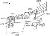
图46示出工作面打开机构4300和滑动件4200B的另一透视图。如本文中所描述,闩锁释放柄部4310(图43中所示)可使轴4410平移。凸瓣4600可联接到轴4410,并且轴4410的平移可使凸瓣4600移位(例如,旋转、移动等等)。凸瓣4600可与推杆4610接合,并且凸瓣的移位可使推杆4610平移。推杆4610可与闩锁4500(图47中所示)接合,并且推杆4610的平移可使闩锁4500相对于滑动件主体4510平移。Figure 46 shows another perspective view of the work
工作面打开机构4300中可包含卡扣4620。在一些示例中,可在导引托架4630中包含卡扣4620,并且导引托架4630可联接到支撑托架4400。闩锁4500可与卡扣4620接合,并且闩锁4500与卡扣4620的接合可限制(例如,固定、保持等)滑动件4200B。在此示例中,当滑动件4200B被限制并且工作面2431与滑动件4200接合时,可将工作面2431维持在闭合配置中。闩锁4500相对于滑动件主体4510(例如,通过推杆4610)的移位可使闩锁4500与卡扣4620脱离,并且允许滑动件4200相对于头部单元2430(图42中所示)平移。因此,工作面2431可转变到打开配置。The work
图47示出工作面打开机构4300和滑动件4200B的又一透视图。为清楚起见,图47中已隐藏支撑托架4400和导引托架4630的部分。在一些示例中,导引托架4630(和支撑托架4400)可限定杆通道4700,并且杆通道4700的大小和形状可设定成接收推杆4610。推杆4610可与杆通道4700以滑动方式接合,并且相对于支撑托架4400(或头部单元2430)平移。如本文件中所描述,推杆4610的平移可使闩锁4500移位,并且允许闩锁4500与卡扣4620脱离。Figure 47 shows yet another perspective view of the work
图48示出工作面打开机构4300的示例的详细透视图。工作面打开机构4300可包含提升系统4800。提升系统4800可使滑动件4200(和工作面2431)偏置远离头部单元4230。在示例中,提升系统4800可包含柱塞4810,并且柱塞4810可与滑动件4200(例如,滑动件4200B)接合并使滑动件4200偏置远离头部单元4230(图42中所示)。在此示例中,当工作面2431与滑动件4200接合时,提升系统4800可使工作面2431偏置远离头部单元4230。在一些示例中,提升系统4800包含多个柱塞4810。例如,第一柱塞4810可位于滑动件4200A附近,而第二柱塞4810可位于滑动件4200B附近。FIG. 48 shows a detailed perspective view of an example of a work
另外,提升系统4800可包含偏置构件4820和提升壳体4830。偏置构件4820(例如,弹簧等)可位于柱塞4810与提升壳体4830之间,并且偏置构件4820可使柱塞4810在第一方向上(例如,向上或朝着与滑动件4200的接合)偏置。在此示例中,柱塞4810可使滑动件4200在第一方向上偏置,因为柱塞4810可与滑动件4200(例如,滑动件4200B)接合。如本文件中更详细地论述,当闩锁4500(图47中所示)与卡扣4620(图46中所示)脱离时,提升系统4800可使工作面2431朝向打开配置偏置。Additionally,
图49示出滑动件4200A的另一透视图。滑动件4200(例如,滑动件4200A)可包含弹出系统4900。当工作面2431(图41中所示)与滑动件4200接合时,弹出系统4900可使工作面2431在第二方向上(例如,沿着滑动件4200A的长度轴线)偏置。在示例中,弹出系统4900可包含弹出凸台4910,并且弹出凸台4910可与工作面2431接合以使工作面2431在第二方向上偏置。Figure 49 shows another perspective view of
滑动件4200可包含滑动件通道4920,并且滑动件通道4920的大小和形状可设定成接收工作面2431。弹出凸台4910可延伸到由滑动件主体4510限定的滑动件通道4920中,并且弹出凸台4910可在工作面2431与滑动件通道4920接合时与工作面2431接合。滑动件通道可由滑动件主体4510和滑动件轨4930限定。弹出凸台4910可与工作面2431接合并且使工作面2431在第二方向上(例如,沿着滑动件通道4920的长度)偏置。在示例中,弹出凸台4910可相对于滑动件主体4510平移,并且因此使工作面2431相对于滑动件主体4510平移。
图50示出滑动件4200A的又一透视图。为清楚起见,图50中已隐藏滑动件4200A的部分。弹出组件4900可包含弹出滑块5000和弹出偏置构件5010。弹出滑块5000可包含弹出凸台4910,并且弹出凸台可延伸穿过由滑动件主体4510在滑动件通道4920中限定的狭槽5020。偏置构件5010(例如,弹簧等)可与弹出滑块5000和滑动件主体4510联接,并且偏置构件5010可使弹出滑块5000(和弹出凸台4910)在第二方向上偏置。在示例中,弹出凸台4910可与滑动件主体4510(例如,狭槽5020的壁)接合以限制弹出滑块5000的运动范围。例如,滑动件主体4510可被配置成停止弹出滑块5000相对于滑动件主体4510的平移。Figure 50 shows yet another perspective view of
图51示出移动工作站2400的正视图。如本文所描述,移动工作站2400可包含头部单元2430、工作面2431和滑动件4200。滑动件4200可限定滑动件通道4920,并且工作面2431可与滑动件通道4920接合。在示例中,工作面2431可包含工作面凸台5100,并且滑动件通道4920的大小和形状可设定成接收工作面凸台5100。工作面凸台5100可与滑动件通道4920以滑动方式接合,并且工作面凸台5100可相对于滑动件通道4920平移。因此,工作面2431可相对于滑动件主体4510平移。另外,弹出凸台4910(图49中所示)可与工作面凸台5100接合,例如以使工作面2431在第二方向上偏置。FIG. 51 shows a front view of the
图52示出头部单元2430和工作面2431的详细侧视图。成角度的托架5200可与工作面2431联接,并且成角度的托架5200可与头部单元2430接合以使工作面2431相对于头部单元2430移位。在示例中,使用者可使工作面2431从打开配置(如图54中所示)朝向闭合配置(如图53中所示)转变。成角度的托架5200可与头部单元2430接合以朝向闭合配置导引工作面2431。例如,成角度的托架5200与头部单元2431的接合可克服由弹出偏置构件5010(图50中所示)提供的偏置并且允许工作面2431相对于滑动件主体4510(图50中所示)平移。FIG. 52 shows a detailed side view of the
图53示出头部单元2430、滑动件4200B和工作面打开机构4300的侧视图。为清楚起见,图53中已隐藏头部单元2430、滑动件4200B和工作面打开机构4300的部分。工作面2431在图53中处于闭合配置。另外,工作面打开机构4300在图53中处于锁定配置。提升系统4800的柱塞4810可与滑动件4200B接合。此外,闩锁5000可与卡扣4620接合以将打开机构4300维持在锁定配置中并将工作面2431维持在闭合配置中。FIG. 53 shows a side view of the
图54示出头部单元2430、滑动件4200B和工作面打开机构4300的另一侧视图。为清楚起见,图54中已隐藏头部单元2430、滑动件4200B和工作面打开机构4300的部分。工作面2431在图54中处于打开配置。另外,工作面打开机构4300在图54中处于解锁配置。柱塞4810与滑动件4200B接合,并且滑动件4200B在第一方向(例如,如由箭头5400所示)上偏置。由于闩锁4500与卡扣4620脱离,因此允许工作面2431转变到打开配置(并且允许滑动件4200B围绕铰链4210B旋转,在图42中示出)。如本文件中所描述,推杆4610可与闩锁5000接合以使闩锁5000移位并且使闩锁4500与卡扣4620脱离。FIG. 54 shows another side view of
此外,弹出系统4900可使工作面2431在第二方向(例如,如箭头5410所示)上偏置。在此示例中,工作面2431可相对于滑动件主体4510平移。工作面2431可从滑动件4200A突出,例如以允许使用者接近计算机存储隔室2432(图42中所示)。另外,因为工作面2431处于打开配置,所以可从头部单元2430移除工作面2431。在示例中,使用者可使工作面2431相对于滑动件4200A平移(例如,牵拉、推动等),并且使工作面凸台5100(图51中所示)与滑动件通道4920(图51中所示)脱离。Additionally, pop-
图55示出工作面打开机构4300和滑动件4200B的侧视图。打开机构4300可包含锁5500(例如,钥匙锁、密码锁等)。锁5500可抑制对闩锁释放柄部4310(图43中所示)的操控。因此,锁5500可防止将打开机构4300从锁定配置转变到解锁配置。Figure 55 shows a side view of the work
各种备注和示例Various notes and examples
方面1可包含或使用主题(例如设备、系统、装置、方法、用于执行动作的构件、或包含指令的装置可读介质,所述指令在由装置执行时可使装置执行动作),例如可包含或使用移动工作站,所述移动工作站包括:高度可调整提升件;头部单元组件,其联接到所述提升件;工作面,其联接到所述头部单元组件并且被配置成相对于所述头部单元组件在打开配置与闭合配置之间转换;第一滑动件,其以可旋转方式联接到所述头部单元组件并且与所述工作面接合,其中所述第一滑动件包含被配置成相对于所述第一滑动件的第一滑动件主体平移的第一闩锁;以及工作面打开机构,其具有锁定配置和解锁配置,所述工作面打开机构包含:闩锁释放柄部,其以可移动方式联接到所述头部单元组件,其中所述闩锁释放柄部的移动被配置成使所述工作面打开机构在所述锁定配置与所述解锁配置之间转变;释放组件,其联接到所述闩锁释放柄部并且被配置成选择性地与所述第一闩锁接合;提升系统,其被配置成使所述工作面偏置远离所述头部单元组件;以及卡扣,其被配置成与所述第一闩锁接合以限制所述第一滑动件并将所述工作面维持在所述闭合配置中。Aspect 1 may comprise or use subject matter (e.g., an apparatus, system, device, method, means for performing an action, or a device-readable medium comprising instructions that, when executed by a device, cause the device to perform the action), such as may Containing or using a mobile workstation comprising: a height adjustable lift; a head unit assembly coupled to the lift; a work surface coupled to the head unit assembly and configured relative to the the head unit assembly transitions between an open configuration and a closed configuration; a first slider rotatably coupled to the head unit assembly and engaged with the work surface, wherein the first slider includes a a first latch configured to translate relative to the first slide body of the first slide; and a work surface opening mechanism having a locked configuration and an unlocked configuration, the work surface opening mechanism comprising: a latch release handle , which is movably coupled to the head unit assembly, wherein movement of the latch release handle is configured to transition the work surface opening mechanism between the locked configuration and the unlocked configuration; releasing an assembly coupled to the latch release handle and configured to selectively engage the first latch; a lift system configured to bias the work surface away from the head unit assembly; and a catch configured to engage the first latch to restrain the first slide and maintain the work surface in the closed configuration.
方面2可包含或使用或可视需要与方面1的主题组合以视需要包含或使用其中所述工作面被收在所述第一滑动件的工作面通道中,并且所述移动工作站还包括弹出组件,所述弹出组件包含:弹出滑块,其与所述第一滑动件以滑动方式联接,所述弹出滑块包含延伸到所述工作面通道中的弹出凸台;以及弹出弹簧,其被配置成使所述弹出滑块在第一方向上偏置,其中所述弹出滑块与所述工作面接合并使所述工作面在所述第一方向上偏置。Aspect 2 may comprise or use or optionally be combined with the subject matter of aspect 1 to optionally comprise or use wherein said work surface is received in the work surface channel of said first slide and said mobile workstation further comprises an eject an ejection assembly comprising: an ejection slider slidably coupled to the first slider, the ejection slider including an ejection boss extending into the work surface channel; and an ejection spring which is The eject slider is configured to bias in a first direction, wherein the eject slider engages the work surface and biases the work surface in the first direction.
方面3可包含或使用或可视需要与方面2的主题组合以视需要包含或使用其中所述弹出凸台通过狭槽延伸到所述工作面通道中,并且所述狭槽沿着所述工作面通道的长度延伸第一距离。Aspect 3 may comprise or use or optionally be combined with the subject matter of aspect 2 to optionally comprise or use wherein said pop-up boss extends into said work surface channel through a slot, and said slot is along said work surface The length of the face channel extends a first distance.
方面4可包含或使用或可视需要与方面3的主题组合以视需要包含或使用其中所述弹出凸台被配置成与所述狭槽的壁接合,并且所述弹出凸台与所述狭槽的壁的接合会防止所述弹出凸台相对于所述第一滑动件平移。Aspect 4 may comprise or use or optionally be combined with the subject matter of aspect 3 to optionally comprise or use wherein said eject boss is configured to engage a wall of said slot and said eject boss is in contact with said slot. Engagement of the walls of the slot prevents translation of the eject boss relative to the first slide.
方面5可包含或使用或可视需要与方面2到4中的一个或任何组合的主题组合以视需要包含或使用成角度的托架,所述成角度的托架与所述工作面的一部分联接并且被配置成与所述头部单元组件接合,其中所述成角度的托架与所述头部单元组件的接合使所述工作面在第二方向上移位并且克服弹出弹簧的偏置。Aspect 5 may comprise or use or optionally combine with the subject matter of one or any combination of aspects 2 to 4 to optionally comprise or use an angled bracket which engages a portion of said work surface coupled and configured to engage the head unit assembly, wherein engagement of the angled bracket with the head unit assembly displaces the work surface in a second direction and overcomes the bias of an ejection spring .
方面6可包含或使用或可视需要与方面2到5中的一个或任何组合的主题组合以视需要包含或使用其中所述弹出组件位于所述铰链附近。Aspect 6 may comprise or use or optionally combine with the subject matter of one or any combination of aspects 2 to 5 to optionally comprise or use wherein said pop-up assembly is located near said hinge.
方面7可包含或使用或可视需要与方面1到6中的一个或任何组合的主题组合以视需要包含或使用其中所述工作面打开机构包含:轴,其与所述闩锁释放柄部联接并且与所述头部单元以旋转方式联接;凸瓣,其联接到所述轴,其中所述闩锁释放柄部的移动使所述轴旋转并使所述凸瓣移位;以及推杆,其与所述头部单元以滑动方式接合并且被配置成与所述闩锁接合,其中所述凸瓣与推杆接合,并且所述凸瓣的移位使所述推杆相对于所述头部单元平移,其中所述推杆相对于所述头部单元的平移选择性地使所述推杆与所述闩锁接合以使所述闩锁相对于所述第一滑动件平移并允许所述闩锁与所述卡扣脱离。Aspect 7 may comprise or use or optionally combine with the subject matter of one or any combination of aspects 1 to 6 to optionally comprise or use wherein said work surface opening mechanism comprises: a shaft which engages said latch release handle coupled and rotationally coupled with the head unit; a lobe coupled to the shaft, wherein movement of the latch release handle rotates the shaft and displaces the lobe; and a push rod , which slideably engages the head unit and is configured to engage the latch, wherein the lobes engage the push rod and displacement of the lobes causes the push rod to move relative to the head unit translation, wherein translation of the push rod relative to the head unit selectively engages the push rod with the latch to translate the latch relative to the first slide and allow The latch is disengaged from the buckle.
方面8可包含或使用或可视需要与方面7的主题组合以视需要包含或使用导引托架,所述导引托架与所述头部单元组件联接,并且所述导引托架的大小和形状设定成接收所述推杆。Aspect 8 may comprise or use or optionally be combined with the subject matter of aspect 7 to optionally comprise or use a guide bracket coupled to said head unit assembly and whose Sized and shaped to receive said push rod.
方面9可包含或使用或可视需要与方面1到8中的一个或任何组合的主题组合以视需要包含或使用其中所述工作面与所述第一滑动件以滑动方式联接,并且所述工作面可从所述第一滑动件移除。Aspect 9 may comprise or use or optionally combine with the subject matter of one or any combination of aspects 1 to 8 to optionally comprise or use wherein said working surface is slidingly coupled with said first slide, and said The working surface is removable from the first slide.
方面10可包含或使用或可视需要与方面1到9中的一个或任何组合的主题组合以视需要包含或使用其中所述提升系统包含:柱塞,其被配置成与所述第一滑动件接合;偏置构件,其定位于所述头部单元组件与所述柱塞之间并且被配置成使所述柱塞在第一方向上偏置,其中所述柱塞与所述第一滑动件的接合使所述第一滑动件在所述第一方向上偏置。Aspect 10 may comprise or use or optionally combine with the subject matter of one or any combination of aspects 1 to 9 to optionally comprise or use wherein said lifting system comprises: a plunger configured to slide with said first a biasing member positioned between the head unit assembly and the plunger and configured to bias the plunger in a first direction, wherein the plunger is aligned with the first Engagement of the sliders biases the first slider in the first direction.
方面11可包含或使用或可视需要与方面1到10中的一个或任何组合的主题组合以视需要包含或使用其中所述工作面被配置成收在所述第一滑动件的工作面通道中,并且所述移动工作站还包括弹出组件,所述弹出组件包含:弹出滑块,其与所述第一滑动件以滑动方式联接,所述弹出滑块包含延伸到所述工作面通道中的弹出凸台;以及弹出弹簧,其被配置成使所述弹出滑块在第一方向上偏置,其中所述弹出滑块被配置成与所述工作面接合并使所述工作面在所述第一方向上偏置。Aspect 11 may comprise or use or optionally combine with the subject matter of one or any combination of aspects 1 to 10 to optionally comprise or use a work surface channel wherein said work surface is configured to be received in said first slide , and the mobile workstation further includes an eject assembly including an eject slider slidably coupled to the first slider, the eject slider including a an eject boss; and an eject spring configured to bias the eject slider in a first direction, wherein the eject slider is configured to engage the work surface and cause the work surface to move in the second direction. One side is biased upwards.
方面12可包含或使用或可视需要与方面1到11中的一个或任何组合的主题组合以视需要包含或使用第二滑动件,所述第二滑动件以可旋转方式联接到所述头部单元组件并且与所述工作面接合,其中所述第二滑动件包含被配置成相对于所述第二滑动件平移的第二闩锁,并且其中所述释放组件被配置成选择性地与所述第二闩锁接合。Aspect 12 may comprise or use or optionally combine with the subject matter of one or any combination of aspects 1 to 11 to optionally comprise or use a second slider rotatably coupled to the head unit assembly and engages the work surface, wherein the second slide includes a second latch configured to translate relative to the second slide, and wherein the release assembly is configured to selectively engage with The second latch engages.
方面13可包含或使用或可视需要与方面1到12中的一个或任何组合的主题组合以视需要包含或使用存储隔室,所述存储隔室被配置成接收一个或多个电子装置。Aspect 13 may comprise or use or optionally combine with the subject matter of one or any combination of aspects 1 to 12 to optionally comprise or use a storage compartment configured to receive one or more electronic devices.
方面14可包含或使用或可视需要与方面1到13中的一个或任何组合的主题组合以视需要包含或使用其中所述铰链位于所述第一滑动件的一端附近。Aspect 14 may comprise or use or optionally combine with the subject matter of one or any combination of aspects 1 to 13 to optionally comprise or use wherein said hinge is located near one end of said first slide.
方面15可包含或使用主题(例如设备、系统、装置、方法、用于执行动作的构件、或包含指令的装置可读介质,所述指令在由装置执行时可使装置执行动作),例如可包含或使用用于移动工作站的工作面打开机构,所述工作面打开机构包括:支撑托架;闩锁释放柄部,其以可移动方式联接到所述支撑托架,其中所述闩锁释放柄部的移动被配置成使所述工作面打开机构在锁定配置与解锁配置之间转换;释放组件,其联接到所述闩锁释放柄部并且被配置成选择性地与闩锁接合;提升系统,其被配置成使第一滑动件偏置远离所述支撑托架;以及卡扣,其被配置成与所述闩锁接合以限制所述滑动件并将所述工作面维持在所述闭合配置中。Aspect 15 may comprise or use subject matter (e.g., an apparatus, system, device, method, means for performing an action, or a device-readable medium comprising instructions that, when executed by a device, cause the device to perform the action), such as may Contains or uses a work surface opening mechanism for a mobile workstation, the work surface opening mechanism comprising: a support bracket; a latch release handle movably coupled to the support bracket, wherein the latch releases movement of the handle configured to transition the face opening mechanism between a locked configuration and an unlocked configuration; a release assembly coupled to the latch release handle and configured to selectively engage a latch; lifting a system configured to bias the first slide away from the support bracket; and a catch configured to engage the latch to restrain the slide and maintain the work surface at the in closed configuration.
方面16可包含或使用或可视需要与方面15的主题组合以视需要包含或使用:轴,其与所述闩锁释放柄部联接并且与所述支撑托架以旋转方式联接;第一凸瓣,其联接到所述轴,其中所述闩锁释放柄部的移动使所述轴旋转并使所述第一凸瓣移位;以及第一推杆,其与所述支撑托架以滑动方式接合并且被配置成与所述闩锁接合,其中所述第一凸瓣与第一推杆接合,并且所述第一凸瓣的移位使所述第一推杆相对于所述支撑托架平移,其中所述第一推杆相对于所述支撑托架的平移被配置成选择性地使所述第一推杆与所述闩锁接合以使所述闩锁平移,从而使所述第一闩锁与所述卡扣脱离。Aspect 16 may comprise or use or optionally be combined with the subject matter of Aspect 15 to optionally comprise or use: a shaft coupled with said latch release handle and rotatably coupled with said support bracket; a first lug a flap coupled to the shaft, wherein movement of the latch release handle rotates the shaft and displaces the first lobe; and a first push rod slides with the support bracket and configured to engage the latch, wherein the first lobe engages the first push rod, and displacement of the first lobe causes the first push rod relative to the support bracket bracket translation, wherein translation of the first pushrod relative to the support bracket is configured to selectively engage the first pushrod with the latch to translate the latch so that the The first latch is disengaged from the buckle.
方面17可包含或使用或可视需要与方面16的主题组合以视需要包含或使用其中所述闩锁是第一闩锁并且所述卡扣是第一卡扣,并且所述工作面打开机构还包括:第二凸瓣,其联接到所述轴,其中所述闩锁释放柄部的移动使所述轴旋转并使所述第二凸瓣移位;以及第二推杆,其与所述支撑托架以滑动方式接合并且被配置成与所述第二闩锁接合,其中所述第二凸瓣与所述第二推杆接合,并且所述第二凸瓣的移位使所述第二推杆相对于所述支撑托架平移,其中所述第二第一推杆相对于所述支撑托架的平移被配置成选择性地使所述第二推杆与第二闩锁接合以使所述第二闩锁平移,以使所述第二闩锁与第二卡扣脱离。Aspect 17 may comprise or use or optionally combine with the subject matter of aspect 16 to optionally comprise or use wherein said latch is a first latch and said catch is a first catch and said work surface opening mechanism Also included: a second lobe coupled to the shaft, wherein movement of the latch release handle rotates the shaft and displaces the second lobe; and a second pushrod is coupled to the shaft. The support bracket is slidably engaged and configured to engage the second latch, wherein the second lobe engages the second push rod, and displacement of the second lobe causes the A second push rod translates relative to the support bracket, wherein translation of the second first push rod relative to the support bracket is configured to selectively engage the second push rod with a second latch The second latch is translated to disengage the second latch from the second buckle.
方面18可包含或使用或可视需要与方面15到17中的一个或任何组合的主题组合以视需要包含或使用其中所述提升系统包含:第一柱塞,其被配置成与所述第一滑动件接合;第一偏置构件,其位于第一提升壳体与所述第一柱塞之间并且被配置成使所述第一柱塞在第一方向上偏置。Aspect 18 may comprise or use or optionally combine with the subject matter of one or any combination of aspects 15 to 17 to optionally comprise or use wherein said lifting system comprises: a first plunger configured to cooperate with said second A slider engages; a first biasing member positioned between the first lift housing and the first plunger and configured to bias the first plunger in a first direction.
方面19可包含或使用或可视需要与方面18的主题组合以视需要包含或使用其中所述提升系统包含:第二柱塞,其被配置成与第二滑动件接合;第二偏置构件,其位于第二提升壳体与所述第二柱塞之间并且被配置成使所述第二柱塞在所述第一方向上偏置。Aspect 19 may comprise or use or optionally combine with the subject matter of aspect 18 to optionally comprise or use wherein said lifting system comprises: a second plunger configured to engage a second slide; a second biasing member , which is located between the second lift housing and the second plunger and is configured to bias the second plunger in the first direction.
方面20可包含或使用或可视需要与方面15到5中的一个或任何组合的主题组合以视需要包含或使用导引托架,所述导引托架与所述头部单元组件联接,并且所述导引托架的大小和形状设定成接收所述推杆。Aspect 20 may comprise or use or optionally combine with the subject matter of one or any combination of aspects 15 to 5 to optionally comprise or use a guide bracket coupled to said head unit assembly, And the guide bracket is sized and shaped to receive the push rod.
方面21可包含或使用主题(例如设备、系统、装置、方法、用于执行动作的构件、或包含指令的装置可读介质,所述指令在由装置执行时可使装置执行动作),例如可包含或使用被配置成联接到竖直支撑表面的倾翻式工作站,所述倾翻式工作站包括:工作面;被配置成联接到所述竖直支撑表面的壁安装组件,所述壁安装组件包含框架和相对于所述框架平移的滑动托架、被配置成与所述工作面联接的支撑托架,其中所述支撑托架通过铰链联接到所述滑动托架,并且其中所述支撑托架被配置成围绕所述铰链旋转;以及锁定组件,其具有锁定配置和解锁配置,其中在所述锁定配置中,所述锁定组件与所述滑动托架接合且所述工作面处于水平第一位置,并且Aspect 21 may comprise or use subject matter (e.g., an apparatus, system, device, method, means for performing an action, or a device-readable medium comprising instructions that, when executed by a device, cause the device to perform an action), such as may Contains or uses a tilting workstation configured to be coupled to a vertical support surface, the tilting workstation comprising: a work surface; a wall mount assembly configured to be coupled to the vertical support surface, the wall mount assembly a support bracket comprising a frame and a sliding bracket that translates relative to the frame, configured to couple with the work surface, wherein the support bracket is hingedly coupled to the sliding bracket, and wherein the support bracket a frame configured to rotate about the hinge; and a locking assembly having a locked configuration and an unlocked configuration, wherein in the locked configuration, the locking assembly is engaged with the sliding bracket and the work surface is horizontal first location, and
在所述解锁配置中,所述锁定组件与所述滑动托架脱离且所述工作面被配置成平移到竖直第二位置。In the unlocked configuration, the locking assembly is disengaged from the slide bracket and the work surface is configured to translate to a vertical second position.
方面22可包含或使用或可视需要与方面21的主题组合以视需要包含或使用与滑动托架联接的闩锁组件,其中所述闩锁组件限定销通道;与所述滑动托架联接的销;并且其中所述销通道的大小和形状设定成接收所述销,并且将所述销接收于所述销通道内会将所述锁定组件配置在所述锁定配置中。Aspect 22 may comprise or use or optionally combine with the subject matter of Aspect 21 to optionally comprise or use a latch assembly coupled to a sliding bracket, wherein the latch assembly defines a pin channel; a pin; and wherein the pin channel is sized and shaped to receive the pin, and receiving the pin within the pin channel configures the locking assembly in the locked configuration.
方面23可包含或使用或可视需要与方面21或2中的一个或任何组合的主题组合以视需要包含或使用其中所述闩锁组件包含:第一臂,其限定所述销通道;第二臂,其通过闩锁铰链与所述第一臂联接;以及闩锁致动器,其与所述第二臂联接,其中所述闩锁致动器的移动使所述第二臂和所述第一臂围绕枢轴旋转。Aspect 23 may comprise or use or optionally combine with the subject matter of one or any combination of aspects 21 or 2 to optionally comprise or use wherein said latch assembly comprises: a first arm defining said pin channel; two arms, which are coupled to the first arm by a latch hinge; and a latch actuator, which is coupled to the second arm, wherein movement of the latch actuator causes the second arm to The first arm rotates about a pivot.
方面24可包含或使用或可视需要与方面21到3中的一个或任何组合的主题组合以视需要包含或使用其中所述壁安装组件包含:第一附接机构,其被配置成与第一带槽托架接合;第一附接主体;第一凸台,其包含在第一方向上取向的第一钩突出部;第二凸台,其包含在与所述第一方向相反的第二方向上取向的第二钩突出部;并且其中所述第二凸台被配置成相对于所述附接主体平移,并且所述第二凸台的平移会改变所述第一凸台与所述第二凸台之间的第一距离。Aspect 24 may comprise or use or optionally combine with the subject matter of one or any combination of aspects 21 to 3 to optionally comprise or use wherein said wall mount assembly comprises: a first attachment mechanism configured to mate with a second a slotted bracket engagement; a first attachment body; a first boss comprising a first hook protrusion oriented in a first direction; a second boss comprising a first hook protrusion oriented in a first direction opposite to said first direction a second hook projection oriented in two directions; and wherein the second boss is configured to translate relative to the attachment body, and translation of the second boss changes the relationship between the first boss and the first boss The first distance between the second bosses.
方面25可包含或使用或可视需要与方面21到4中的一个或任何组合的主题组合以视需要包含或使用其中所述壁安装组件包含:第二附接机构,其被配置成与第二带槽托架接合;第二附接主体,第三凸台,其包含在所述第一方向上取向的第三钩突出部;第四凸台,其包含在所述第二方向上取向的第四钩突出部;并且其中所述第三凸台或所述第四凸台被配置成相对于所述附接主体平移,并且所述第三凸台或所述第四凸台的平移会改变所述第三凸台与所述第四凸台之间的第二距离。Aspect 25 may comprise or use or optionally combine with the subject matter of one or any combination of aspects 21 to 4 to optionally comprise or use wherein said wall mount assembly comprises: a second attachment mechanism configured to mate with the first Two slotted brackets engage; a second attachment body, a third boss including a third hook protrusion oriented in said first direction; a fourth boss including a third boss oriented in said second direction and wherein the third boss or the fourth boss is configured to translate relative to the attachment body, and the translation of the third boss or the fourth boss The second distance between the third boss and the fourth boss will be changed.
方面26可包含或使用或可视需要与方面24或25中的一个或任何组合的主题组合以视需要包含或使用其中所述壁安装组件包含:支撑构件,其被配置成跨在所述第一附接机构与所述第二附接机构之间,其中所述支撑构件包含第一键和第二键;其中所述第一附接主体包含被配置成接收所述第一键的第一键槽,并且所述第二附接主体包含被配置成接收所述第二键的第二键槽;并且其中所述框架被配置成与所述支撑构件接合以使所述框架与结构联接。Aspect 26 may comprise or use or optionally combine with the subject matter of one or any combination of aspects 24 or 25 to optionally comprise or use wherein said wall mount assembly comprises: a support member configured to straddle said second Between an attachment mechanism and the second attachment mechanism, wherein the support member includes a first key and a second key; wherein the first attachment body includes a first key configured to receive the first key a keyway, and the second attachment body includes a second keyway configured to receive the second key; and wherein the frame is configured to engage the support member to couple the frame to a structure.
方面27可包含或使用或可视需要与方面1到26中的任何一个或多个的任何部分中的任一部分或组合进行组合以包含或使用主题,所述主题可包含用于执行方面1到26中的任何一个或多个功能的构件。Aspect 27 may comprise or use or may be combined as desired with any part or combination of any one or more of any one or more of aspects 1 to 26 to comprise or use a subject matter which may comprise aspects for carrying out aspects 1 to 26 26 in any one or more functional components.
以上描述包含对附图的参考,附图形成具体实施方式的一部分。各图以说明方式示出其中可实践本发明的具体实施例。这些实施例在本文中也称作“示例”。此类示例可包含除了所示或所描述的那些元件之外的元件。然而,本发明人还预期其中仅提供所示或所描述的那些元件的示例。此外,本发明人还预期使用相对于特定示例(或其一个或多个方面)或相对于本文所示或描述的其它示例(或其一个或多个方面)而示出或描述的那些元件的任何组合或排列的示例(或其一个或多个方面)。The above description contains references to the accompanying drawings, which form a part of the Detailed Description. The figures show, by way of illustration, specific embodiments in which the invention may be practiced. These embodiments are also referred to herein as "examples." Such examples may include elements in addition to those shown or described. However, the inventors also contemplate examples in which only those elements shown or described are provided. In addition, the inventors also contemplate the use of those elements shown or described with respect to a particular example (or one or more aspects thereof) or with respect to other examples (or one or more aspects thereof) shown or described herein. Examples (or one or more aspects thereof) in any combination or permutation.
如果本文件与通过引用方式并入的任何文件之间出现不一致的用途,以本文件中的用途为准。In the event of inconsistent usage between this document and any document incorporated by reference, the usage in this document controls.
在本文件中,如专利文件中常见,使用术语“一”以包含一个或多于一个,这与“至少一个”或“一个或多个”的任何其它实例或使用无关。在本文件中,术语“或”用于指代非排它性或,使得除非另有指示,否则“A或B”包含“A而非B”、“B而非A”以及“A和B”。在本文件中,术语“包含”和“其中(in which)”用作相应术语“包括”和“其中(wherein)”的通俗等效用语。另外,在所附权利要求书中,术语“包含”和“包括”是开放的,即,包含除了列在权利要求中此类术语后的那些元件之外的元件的系统、装置、物件、组合物、调配物或过程仍被认为处于所述权利要求的范围内。此外,在所附权利要求书中,用语“第一”、“第二”和“第三”等仅用作标记,而并非旨在对其对象施加数字要求。In this document, as is common in patent documents, the term "a" is used to include one or more than one, regardless of any other instance or use of "at least one" or "one or more". In this document, the term "or" is used to denote a non-exclusive or such that unless otherwise indicated, "A or B" includes "A and not B", "B and not A" and "A and B ". In this document, the terms "comprising" and "in which" are used as colloquial equivalents of the corresponding terms "including" and "wherein". Additionally, in the appended claims, the terms "comprising" and "comprising" are open-ended, i.e., systems, devices, articles, combinations comprising elements other than those listed after such term in the claims substances, formulations or processes are still considered to be within the scope of the claims. Furthermore, in the appended claims, the terms "first", "second", and "third", etc. are used as labels only and are not intended to impose numerical requirements on their objects.
除非上下文另有指示,否则几何术语,例如“平行”、“垂直”、“圆形”或“方形”,并非旨在要求绝对数学精度。实际上,此类几何术语允许因制造或同等功能所致的变化。例如,如果将元件描述为“圆形”或“大体上圆形”,那么此描述仍涵盖并非精确圆形的部件(例如,略微呈长椭圆形或是多个边的多边形的部件)。Geometric terms such as "parallel", "perpendicular", "circle" or "square" are not intended to require absolute mathematical precision unless the context dictates otherwise. Indeed, such geometric terms allow for variations due to manufacturing or equivalent functionality. For example, if an element is described as "circular" or "substantially circular," that description would still cover components that are not exactly circular (eg, components that are somewhat oblong or multi-sided polygons).
以上描述旨在为说明性而非限制性的。例如,上文所描述的示例(或其一个或多个方面)可彼此组合使用。例如所属领域的技术人员在查阅以上描述后可使用其它实施例。提供摘要以符合37C.F.R.§1.72(b),从而允许阅读者快速确定技术公开的性质。在理解所述摘要将不用于解释或限制权利要求书的范围或意义的情况下提交所述摘要。另外,在以上具体实施方式中,可将各种特征分组在一起以简化本公开。此情况不应解释为期望未要求的公开特征对任何权利要求来说是必不可少的。实际上,发明主题可在于比特定公开实施例的所有特征要少。因此,所附权利要求书特此作为示例或实施例并入具体实施方式中,其中每个权利要求作为单独实施例单独存在,并且预期此类实施例可彼此组合成各种组合或排列。本发明的范围应参考所附权利要求书以及此类权利要求所授予的等同物的完整范围而确定。The above description is intended to be illustrative rather than limiting. For example, the examples described above (or one or more aspects thereof) may be used in combination with each other. Other embodiments may be utilized, for example, by those of ordinary skill in the art upon reviewing the above description. The abstract is provided to comply with 37 C.F.R. §1.72(b), allowing the reader to quickly ascertain the nature of the technical disclosure. It is submitted with the understanding that it will not be used to interpret or limit the scope or meaning of the claims. In addition, in the foregoing Detailed Description, various features may be grouped together in order to simplify the disclosure. This fact should not be interpreted as intending that an unclaimed disclosed feature is essential to any claim. Indeed, inventive subject matter may lie in less than all features of a particular disclosed embodiment. Thus, the appended claims are hereby incorporated into the detailed description as examples or embodiments, where each claim stands on its own as a separate embodiment, and it is contemplated that such embodiments may be combined with each other in various combinations or permutations. The scope of the invention should be determined with reference to the appended claims, along with the full scope of equivalents to which such claims are entitled.
Claims (20)
Applications Claiming Priority (6)
| Application Number | Priority Date | Filing Date | Title |
|---|---|---|---|
| US201862637562P | 2018-03-02 | 2018-03-02 | |
| US62/637,562 | 2018-03-02 | ||
| US201862721351P | 2018-08-22 | 2018-08-22 | |
| US62/721,351 | 2018-08-22 | ||
| PCT/US2019/020435WO2019169355A1 (en) | 2018-03-02 | 2019-03-01 | Height adjustable platforms and associated mechanisms |
| CN201980016854.XACN112165886B (en) | 2018-03-02 | 2019-03-01 | Height adjustable platform and associated mechanism |
Related Parent Applications (1)
| Application Number | Title | Priority Date | Filing Date |
|---|---|---|---|
| CN201980016854.XADivisionCN112165886B (en) | 2018-03-02 | 2019-03-01 | Height adjustable platform and associated mechanism |
Publications (1)
| Publication Number | Publication Date |
|---|---|
| CN115281447Atrue CN115281447A (en) | 2022-11-04 |
Family
ID=67768276
Family Applications (2)
| Application Number | Title | Priority Date | Filing Date |
|---|---|---|---|
| CN202210974101.3APendingCN115281447A (en) | 2018-03-02 | 2019-03-01 | Height adjustable platform and associated mechanism |
| CN201980016854.XAActiveCN112165886B (en) | 2018-03-02 | 2019-03-01 | Height adjustable platform and associated mechanism |
Family Applications After (1)
| Application Number | Title | Priority Date | Filing Date |
|---|---|---|---|
| CN201980016854.XAActiveCN112165886B (en) | 2018-03-02 | 2019-03-01 | Height adjustable platform and associated mechanism |
Country Status (5)
| Country | Link |
|---|---|
| US (6) | US10646033B2 (en) |
| CN (2) | CN115281447A (en) |
| CA (2) | CA3192834A1 (en) |
| DE (1) | DE112019001110T5 (en) |
| WO (1) | WO2019169355A1 (en) |
Families Citing this family (9)
| Publication number | Priority date | Publication date | Assignee | Title |
|---|---|---|---|---|
| CA3092642C (en) | 2018-03-02 | 2023-07-04 | Ergotron, Inc. | Height adjustable platforms and associated mechanisms |
| CA3192834A1 (en) | 2018-03-02 | 2019-09-06 | Ergotron, Inc. | Height adjustable platforms and associated mechanisms |
| DE202019002176U1 (en)* | 2019-05-20 | 2019-05-29 | Oelschläger Metalltechnik GmbH | Operating device for a table and table with the same |
| CN116557694A (en) | 2019-07-10 | 2023-08-08 | 爱格升公司 | Display mounting system and method |
| US11613286B2 (en)* | 2019-09-06 | 2023-03-28 | Covidien Lp | Cart for medical equipment |
| CN110792885B (en)* | 2019-10-30 | 2021-04-02 | 广州视源电子科技股份有限公司 | Display screen support, display screen assembly and installation method of display screen assembly |
| US11319199B2 (en)* | 2020-07-06 | 2022-05-03 | Chao Shuan Liu | Rotating structure for a bearing section of a workstation |
| US20240407543A1 (en)* | 2021-09-30 | 2024-12-12 | Ergotron, Inc. | A workstation with modular construction |
| CN117082998B (en)* | 2021-12-22 | 2025-05-27 | 爱格升公司 | Adjustable and stowable workstation assembly |
Citations (5)
| Publication number | Priority date | Publication date | Assignee | Title |
|---|---|---|---|---|
| CH653464A5 (en)* | 1980-04-22 | 1985-12-31 | Bend S A | Device for pivoting and inclining a video display unit (VDU) |
| CN1734680A (en)* | 2004-08-12 | 2006-02-15 | Lg电子株式会社 | Mount for image display apparatus |
| US20130082156A1 (en)* | 2011-09-30 | 2013-04-04 | Imperial Stamping Corporation | Articulating mount for a display |
| US20140265193A1 (en)* | 2013-03-14 | 2014-09-18 | Jeffrey P. Stark | Height adjustable support |
| US20150014493A1 (en)* | 2013-07-09 | 2015-01-15 | Dongguan Cheng Jie Electronics Co., Ltd. | Display Elevating Device |
Family Cites Families (101)
| Publication number | Priority date | Publication date | Assignee | Title |
|---|---|---|---|---|
| US741382A (en) | 1902-03-24 | 1903-10-13 | Chicago Writing Machine Company | Folding bracket for telephones, &c. |
| US874014A (en)* | 1906-01-25 | 1907-12-17 | Morris Kurtzon | Adjustable bracket. |
| US1034365A (en)* | 1911-10-25 | 1912-07-30 | Siegfried Hauser | Shelf-frame. |
| GB408382A (en) | 1932-11-24 | 1934-04-12 | Ernest Vaughan | Improvements in or relating to folding tables and the like |
| CH543256A (en) | 1971-09-14 | 1973-10-31 | Castelli Sas Anonima | Folding table with folding legs in pairs |
| US4353263A (en) | 1979-10-01 | 1982-10-12 | Nelson And Johnson | Power transmission mechanism |
| US4457406A (en) | 1980-06-06 | 1984-07-03 | P. L. Porter Company | Improved friction lock |
| US4671481A (en)* | 1985-10-15 | 1987-06-09 | Herman Miller, Inc. | Antidislodgement clips |
| JP2681272B2 (en) | 1987-07-10 | 1997-11-26 | 積水ハウス株式会社 | Tubular pile gripping device |
| US4969403A (en)* | 1988-11-08 | 1990-11-13 | Edtech Company | Automatic vertically adjustable work surface |
| US5116007A (en)* | 1990-09-13 | 1992-05-26 | E.Z. Shelf Company | Eccentric disc lock bracket |
| US5454638A (en)* | 1991-03-07 | 1995-10-03 | Donnelly Technology, Inc. | Adjustable refrigerator shelving |
| US5219045A (en) | 1991-06-19 | 1993-06-15 | P. L. Porter Company | Linear mechanical lock with one-piece lock housing |
| US5441129A (en) | 1993-06-08 | 1995-08-15 | P. L. Porter Co. | Precision linear mechanical lock |
| US5568843A (en) | 1993-06-08 | 1996-10-29 | P. L. Porter Co. | Precision linear mechanical lock |
| US5472103A (en)* | 1994-05-25 | 1995-12-05 | Merl; Milton J. | Segmented shelving construction |
| US5538213A (en)* | 1994-09-21 | 1996-07-23 | Brown Office Systems, Inc. | Bracket for shelving, furniture and the like |
| US5673633A (en) | 1995-05-31 | 1997-10-07 | Pfister; Joel W. | Table leg system |
| US5927214A (en) | 1996-06-10 | 1999-07-27 | Ahc Inc. | Flat folding table |
| US5794470A (en) | 1996-06-25 | 1998-08-18 | P.L. Porter Co. | Mechanical seat lock |
| JPH1017927A (en) | 1996-07-03 | 1998-01-20 | Daido Steel Co Ltd | Method for producing δ-containing ferritic austenitic stainless steel |
| US5706739A (en) | 1996-12-12 | 1998-01-13 | Ergotech (1993) Inc. | Height adjustable counterbalance workstation |
| US6164419A (en) | 1999-04-21 | 2000-12-26 | P. L. Porter Co. | Mechanical seat lock with translating rod that does not rotate |
| US6286441B1 (en)* | 1999-04-30 | 2001-09-11 | Steelcase Development Corporation | Height adjustable work surface and control therefor |
| JP2003505776A (en) | 1999-07-27 | 2003-02-12 | デニス ペイン,ロジャー | Apparatus for supporting a data input device such as a computer keyboard |
| US6726168B2 (en) | 1999-10-15 | 2004-04-27 | Compx International Inc. | Adjustable computer keyboard platform support mechanism |
| US6336618B1 (en) | 1999-10-15 | 2002-01-08 | Compx International Inc | Adjustable computer keyboard platform support mechanism |
| US6276660B1 (en) | 1999-12-07 | 2001-08-21 | General Motors Corporation | Rotary piston actuator with selective one-way wrapped spring clutches |
| US6315361B1 (en) | 2000-04-24 | 2001-11-13 | Porter Engineered Systems. | Seat adjustment and dumping system with memory |
| CA2350134A1 (en) | 2000-06-08 | 2001-12-08 | Dennis L. Long | Device for controlling the rotation of a shaft |
| DE10050807A1 (en)* | 2000-10-13 | 2002-04-18 | Stoll Sedus Ag | worktable |
| US6575531B1 (en) | 2002-01-08 | 2003-06-10 | Shin Yeh Enterprise Co., Ltd. | Reclining chair with adjustment telescopic tube |
| US6851226B2 (en) | 2002-02-15 | 2005-02-08 | Steelcase Development Corporation | Partition panel with modular appliance mounting arrangement |
| US6905101B1 (en) | 2002-06-11 | 2005-06-14 | Chief Manufacturing Inc. | Adjustable, self-balancing flat panel display mounting system |
| US20050288571A1 (en)* | 2002-08-20 | 2005-12-29 | Welch Allyn, Inc. | Mobile medical workstation |
| US7311211B2 (en)* | 2003-03-17 | 2007-12-25 | Custom Shelving Solutions Ltd. | Stock shelving system |
| US20060185563A1 (en) | 2004-07-30 | 2006-08-24 | Sweere Harry C | Lift mechanism systems and methods |
| US7016164B2 (en) | 2003-07-02 | 2006-03-21 | Hitachi Global Storage Technologies Netherlands B.V | Hard bias structure with enhanced Hc |
| NL1027626C2 (en) | 2004-11-30 | 2006-05-31 | Vogel S Holding Bv | Device suitable for supporting a component. |
| EP1827170B1 (en) | 2004-12-17 | 2016-05-18 | Steelcase Inc. | Height adjustable table |
| US7793903B2 (en) | 2005-06-06 | 2010-09-14 | Milestone Av Technologies Llc | Articulating arm for flat panel display |
| WO2007062214A2 (en) | 2005-11-21 | 2007-05-31 | Clo Systems, Llc | Motorized mount system for repositioning a monitor |
| US7487943B1 (en) | 2006-01-05 | 2009-02-10 | Peerless Industries, Inc. | Dual arm mounting system with vertical adjustment feature |
| US20070227409A1 (en)* | 2006-03-29 | 2007-10-04 | Ching-Shan Chu | UPS uninterruptible power supply mobile computer table structure |
| US20070228680A1 (en)* | 2006-04-03 | 2007-10-04 | Metro Industries Inc. | Modular Workstation |
| US7836833B2 (en) | 2006-05-15 | 2010-11-23 | Aichi Co., Ltd. | Locking device and furniture |
| US7828253B2 (en)* | 2006-06-20 | 2010-11-09 | Meyer Christopher E | Secure shelf for technology workstand |
| TWM308357U (en) | 2006-09-12 | 2007-03-21 | Modernsolid Ind Co Ltd | Panel fixing stand for multiple angle adjustment |
| US20080084147A1 (en)* | 2006-10-06 | 2008-04-10 | Bruce Wallace Brown | Mobile workstation |
| CN101720482B (en) | 2007-01-03 | 2014-02-26 | 迈尔史东视讯科技股份有限公司 | Device mount with selectively positionable tilt axis |
| CA2575492A1 (en) | 2007-01-25 | 2008-07-25 | Guy Chouinard | Adjustable stand for monitor and keyboard |
| WO2008092092A2 (en) | 2007-01-26 | 2008-07-31 | Rubbermaid Incorporated | Work station |
| DE602007003212D1 (en) | 2007-07-06 | 2009-12-24 | Fiat Ricerche | Rotary and / or sliding locking device of a shape memory unlocked bolt |
| US7766311B2 (en) | 2007-07-30 | 2010-08-03 | Takonix Incorporated | Wireform locking device |
| EP2238749A4 (en) | 2008-01-04 | 2011-07-27 | Milestone Av Technologies Llc | Flat panel display mount |
| TWM337221U (en) | 2008-02-01 | 2008-07-21 | ming-xian Huang | Screen holding apparatus |
| US20090315287A1 (en)* | 2008-06-20 | 2009-12-24 | Rossini Alfred P | Mobile Cart |
| US8113076B2 (en) | 2008-08-07 | 2012-02-14 | Itt Manufacturing Enterprises, Inc. | Mechanical positioner for reclining seat assembly |
| US20110215212A1 (en)* | 2008-11-14 | 2011-09-08 | Aydin Keyvanloo | Vertical mounting system |
| TW201030266A (en) | 2009-01-05 | 2010-08-16 | Peerless Ind Inc | Multiple arm articulating mounting system |
| US8038021B2 (en)* | 2009-04-03 | 2011-10-18 | Protrend Co., Ltd | Sectional rack |
| US8286977B2 (en)* | 2009-07-30 | 2012-10-16 | Mela Sciences, Inc. | Medical cart |
| CN102859252B (en)* | 2009-12-07 | 2014-10-22 | 爱格升公司 | Brake stand systems |
| US8250993B2 (en) | 2009-12-18 | 2012-08-28 | Krueger International, Inc. | Laptop computer storage assembly for a work surface |
| US9188275B2 (en) | 2010-07-30 | 2015-11-17 | Ergotron, Inc. | Edge mount positioning apparatus, system, and method |
| CA2826701C (en) | 2011-02-11 | 2020-03-24 | Ergotron, Inc. | Bifocal display positioning apparatus and method |
| US8677911B2 (en) | 2011-02-18 | 2014-03-25 | Rubbermaid Incorporated | Technology cart |
| AU2015224380B2 (en) | 2011-02-22 | 2017-02-02 | 3D Space Arms Pty Ltd | A Support Mechanism |
| US8434629B2 (en)* | 2011-04-08 | 2013-05-07 | Clairson Inc. | Adjustable shelving system with overlapping tracks |
| ES2796798T3 (en)* | 2012-02-08 | 2020-11-30 | Humanscale Corp | Auxiliary cart |
| JP5921673B2 (en)* | 2012-03-29 | 2016-05-24 | 日立アロカメディカル株式会社 | Cart for ultrasonic diagnostic equipment |
| US9027940B2 (en)* | 2012-09-26 | 2015-05-12 | Ergotron, Inc. | Work surface opening mechanism |
| US8947215B2 (en)* | 2012-11-16 | 2015-02-03 | Xerox Corporation | Systems and methods for implementing automated workstation elevation position tracking and control |
| US9167894B2 (en)* | 2013-01-25 | 2015-10-27 | Sparx Smart Pods Inc. | Workstation having automated and powered height, depth and rotational adjusters |
| US20160278514A1 (en) | 2013-02-25 | 2016-09-29 | Anthony Paul Maas | Height Adjustable Work Platform Apparatus |
| CA2902822A1 (en)* | 2013-03-01 | 2014-09-04 | Intermetro Industries Corporation | Mobile computer workstation |
| DE102013213613A1 (en) | 2013-07-11 | 2015-01-15 | BSH Bosch und Siemens Hausgeräte GmbH | Support device for a household appliance, housing for a household appliance and household appliance |
| WO2015026714A1 (en) | 2013-08-19 | 2015-02-26 | Ergotron | Height adjustable desk system and method |
| DE102013109830B4 (en)* | 2013-09-09 | 2020-02-06 | Logicdata Electronic & Software Entwicklungs Gmbh | The invention relates to an ergonomic system for a workplace system. |
| EP2856909A1 (en) | 2013-10-04 | 2015-04-08 | Keysheen Industry (Shanghai) Co., Ltd. | Table with leg pivotably mounted to table top |
| KR20160091982A (en)* | 2013-11-26 | 2016-08-03 | 피오 코포레이션 | Removable and automatically re-latching tray device and method |
| US9241562B2 (en)* | 2013-12-02 | 2016-01-26 | Scott A. Fish | Work station |
| DE102013114289B4 (en)* | 2013-12-18 | 2023-09-07 | Juvema Ag | Shelving system with electrical supply |
| WO2015120557A1 (en)* | 2014-02-17 | 2015-08-20 | Claronav Inc. | Medical cart |
| DE102014104733A1 (en)* | 2014-04-03 | 2015-10-08 | Paul Hettich Gmbh & Co. Kg | Sliding swivel mechanism of a storage of a piece of furniture or household appliance, household appliance and furniture |
| US9420878B2 (en)* | 2014-04-08 | 2016-08-23 | Wl Innovations Llc | Work surface height adjustor with universal mount |
| US9671063B2 (en)* | 2014-05-01 | 2017-06-06 | New Dimensions Research Corporation | Header support system |
| JP6449436B2 (en) | 2014-08-11 | 2019-01-09 | エルゴトロン,インコーポレイティド | Height adjustable desk system and method |
| US9549609B2 (en)* | 2014-10-31 | 2017-01-24 | MyWorld Mediastudio | Mobile mulimedia workstation |
| US9596929B2 (en)* | 2014-11-10 | 2017-03-21 | Eugenia Koulizakis | Portable work support and keyboard/mouse tray and work station and tethered chair |
| CN106572746A (en)* | 2014-12-10 | 2017-04-19 | 休思乐公司 | Height adjustable monitor and keyboard support |
| GB2537091A (en) | 2015-02-12 | 2016-10-12 | Colebrook Bosson Saunders Products Ltd | Apparatus for supporting a load |
| US9999971B2 (en)* | 2015-08-20 | 2018-06-19 | The Boeing Company | Ergonomic automated workstation |
| CA3041754A1 (en)* | 2015-11-13 | 2017-05-18 | Sparx Smartpods Inc. | Systems and methods for controlling an interactive workstation based on biometric input |
| DE102016116831A1 (en)* | 2016-09-08 | 2018-03-08 | Bernstein Ag | Supporting column system for carrying at least one computer device |
| US10058173B2 (en)* | 2016-11-08 | 2018-08-28 | Proos Manufacturing, Inc. | Shelving assembly and method of assembly |
| US10376042B1 (en)* | 2016-12-30 | 2019-08-13 | Simon Nicholas Johnson | Wall-mounted workstation sliding guide assembly |
| CA3052210A1 (en)* | 2017-03-09 | 2018-09-13 | Ergotron, Inc. | Flexible retention systems for portable electronic devices |
| CA3092642C (en) | 2018-03-02 | 2023-07-04 | Ergotron, Inc. | Height adjustable platforms and associated mechanisms |
| CA3192834A1 (en) | 2018-03-02 | 2019-09-06 | Ergotron, Inc. | Height adjustable platforms and associated mechanisms |
| US10323791B1 (en)* | 2018-06-06 | 2019-06-18 | C. D. Great Furniture Co., Ltd. | Displacement structure for a support frame |
- 2019
- 2019-03-01CACA3192834Apatent/CA3192834A1/enactivePending
- 2019-03-01CNCN202210974101.3Apatent/CN115281447A/enactivePending
- 2019-03-01USUS16/290,840patent/US10646033B2/enactiveActive
- 2019-03-01WOPCT/US2019/020435patent/WO2019169355A1/ennot_activeCeased
- 2019-03-01CACA3092573Apatent/CA3092573A1/enactivePending
- 2019-03-01CNCN201980016854.XApatent/CN112165886B/enactiveActive
- 2019-03-01DEDE112019001110.3Tpatent/DE112019001110T5/enactivePending
- 2020
- 2020-04-22USUS16/855,784patent/US11076689B2/enactiveActive
- 2021
- 2021-07-09USUS17/305,546patent/US11564484B2/enactiveActive
- 2023
- 2023-01-04USUS18/150,157patent/US11839294B2/enactiveActive
- 2023-10-05USUS18/481,724patent/US12161220B2/enactiveActive
- 2024
- 2024-11-07USUS18/940,621patent/US20250064205A1/enactivePending
Patent Citations (5)
| Publication number | Priority date | Publication date | Assignee | Title |
|---|---|---|---|---|
| CH653464A5 (en)* | 1980-04-22 | 1985-12-31 | Bend S A | Device for pivoting and inclining a video display unit (VDU) |
| CN1734680A (en)* | 2004-08-12 | 2006-02-15 | Lg电子株式会社 | Mount for image display apparatus |
| US20130082156A1 (en)* | 2011-09-30 | 2013-04-04 | Imperial Stamping Corporation | Articulating mount for a display |
| US20140265193A1 (en)* | 2013-03-14 | 2014-09-18 | Jeffrey P. Stark | Height adjustable support |
| US20150014493A1 (en)* | 2013-07-09 | 2015-01-15 | Dongguan Cheng Jie Electronics Co., Ltd. | Display Elevating Device |
Non-Patent Citations (1)
| Title |
|---|
| (英)瑞德里、(英)强尼编;江宏伟等译;: "《职业安全与健康》", 30 April 2010, 北京:煤炭工业出版社, pages: 422* |
Also Published As
| Publication number | Publication date |
|---|---|
| US20230133573A1 (en) | 2023-05-04 |
| US11839294B2 (en) | 2023-12-12 |
| CN112165886B (en) | 2022-08-23 |
| DE112019001110T5 (en) | 2020-11-12 |
| US20240023706A1 (en) | 2024-01-25 |
| CA3192834A1 (en) | 2019-09-06 |
| CA3092573A1 (en) | 2019-09-06 |
| US20250064205A1 (en) | 2025-02-27 |
| US11076689B2 (en) | 2021-08-03 |
| WO2019169355A1 (en) | 2019-09-06 |
| US20190269239A1 (en) | 2019-09-05 |
| CN112165886A (en) | 2021-01-01 |
| US10646033B2 (en) | 2020-05-12 |
| US11564484B2 (en) | 2023-01-31 |
| US12161220B2 (en) | 2024-12-10 |
| US20220000257A1 (en) | 2022-01-06 |
| US20200352321A1 (en) | 2020-11-12 |
Similar Documents
| Publication | Publication Date | Title |
|---|---|---|
| CN115281447A (en) | Height adjustable platform and associated mechanism | |
| US10274131B2 (en) | Display screen mounting | |
| US8567735B2 (en) | Work station with height adjustment lock | |
| US20200221864A1 (en) | Height adjustable desktop work surface | |
| EP1423030B1 (en) | Adjustable keyboard support assembly | |
| US20070259554A1 (en) | Stand system and method | |
| CN117082998B (en) | Adjustable and stowable workstation assembly | |
| US20230288023A1 (en) | Arm assembly | |
| EP2985506A1 (en) | A mount for a laptop computer | |
| AU2015224380A1 (en) | A Support Mechanism | |
| AU2017219106B2 (en) | A Support Mechanism | |
| JPH08107818A (en) | Fitting structure of holding member for articles, etc. |
Legal Events
| Date | Code | Title | Description |
|---|---|---|---|
| PB01 | Publication | ||
| PB01 | Publication | ||
| SE01 | Entry into force of request for substantive examination | ||
| SE01 | Entry into force of request for substantive examination | ||
| RJ01 | Rejection of invention patent application after publication | ||
| RJ01 | Rejection of invention patent application after publication | Application publication date:20221104 |