CN115280898A - Method and apparatus for service continuity based on path switching from UE to network relay - Google Patents
Method and apparatus for service continuity based on path switching from UE to network relayDownload PDFInfo
- Publication number
- CN115280898A CN115280898ACN202180013386.8ACN202180013386ACN115280898ACN 115280898 ACN115280898 ACN 115280898ACN 202180013386 ACN202180013386 ACN 202180013386ACN 115280898 ACN115280898 ACN 115280898A
- Authority
- CN
- China
- Prior art keywords
- relay
- link
- gnb
- user equipment
- path
- Prior art date
- Legal status (The legal status is an assumption and is not a legal conclusion. Google has not performed a legal analysis and makes no representation as to the accuracy of the status listed.)
- Pending
Links
Images


Classifications
- H—ELECTRICITY
- H04—ELECTRIC COMMUNICATION TECHNIQUE
- H04W—WIRELESS COMMUNICATION NETWORKS
- H04W76/00—Connection management
- H04W76/20—Manipulation of established connections
- H04W76/23—Manipulation of direct-mode connections
- H—ELECTRICITY
- H04—ELECTRIC COMMUNICATION TECHNIQUE
- H04W—WIRELESS COMMUNICATION NETWORKS
- H04W76/00—Connection management
- H04W76/10—Connection setup
- H04W76/14—Direct-mode setup
- H—ELECTRICITY
- H04—ELECTRIC COMMUNICATION TECHNIQUE
- H04W—WIRELESS COMMUNICATION NETWORKS
- H04W24/00—Supervisory, monitoring or testing arrangements
- H04W24/10—Scheduling measurement reports ; Arrangements for measurement reports
- H—ELECTRICITY
- H04—ELECTRIC COMMUNICATION TECHNIQUE
- H04W—WIRELESS COMMUNICATION NETWORKS
- H04W36/00—Hand-off or reselection arrangements
- H04W36/03—Reselecting a link using a direct mode connection
- H04W36/033—Reselecting a link using a direct mode connection in pre-organised networks
- H—ELECTRICITY
- H04—ELECTRIC COMMUNICATION TECHNIQUE
- H04W—WIRELESS COMMUNICATION NETWORKS
- H04W76/00—Connection management
- H04W76/20—Manipulation of established connections
- H—ELECTRICITY
- H04—ELECTRIC COMMUNICATION TECHNIQUE
- H04W—WIRELESS COMMUNICATION NETWORKS
- H04W88/00—Devices specially adapted for wireless communication networks, e.g. terminals, base stations or access point devices
- H04W88/02—Terminal devices
- H04W88/04—Terminal devices adapted for relaying to or from another terminal or user
- H—ELECTRICITY
- H04—ELECTRIC COMMUNICATION TECHNIQUE
- H04W—WIRELESS COMMUNICATION NETWORKS
- H04W92/00—Interfaces specially adapted for wireless communication networks
- H04W92/16—Interfaces between hierarchically similar devices
- H04W92/18—Interfaces between hierarchically similar devices between terminal devices
Landscapes
- Engineering & Computer Science (AREA)
- Computer Networks & Wireless Communication (AREA)
- Signal Processing (AREA)
- Mobile Radio Communication Systems (AREA)
Abstract
Translated fromChinese
Description
Translated fromChinese交叉引用cross reference
本申请是根据35 USC§111(a)提交的,根据35 USC§120和§365(c)基于并要求2020年2月6日递交的,发明名称为“Methods and Apparatus of Path Switch based ServiceContinuity for UE-to-Network Relay”的国际申请号为PCT/CN2020/074410的优先权,且将上述申请合并作为参考。This application is filed under 35 USC §111(a), based upon and required to be filed on February 6, 2020 under 35 USC §120 and §365(c), and is entitled "Methods and Apparatus of Path Switch based Service Continuity for The international application number of UE-to-Network Relay" is the priority of PCT/CN2020/074410, and the above application is incorporated by reference.
技术领域technical field
本发明有关于无线通信,且尤其有关于UE到网络中继的基于路径切换的(path-switch-based)服务连续性(service continuity)。The present invention relates to wireless communication, and in particular to path-switch-based service continuity from UE to network relay.
背景技术Background technique
5G无线电接入技术将成为现代接入网的关键组件,它将解决高通信量增长和日益增长的高带宽连接需求。蜂窝网络中的无线中继可提供扩展的覆盖范围并提高传输可靠性。长期演进(long term evolution,LTE)网络引入了3GPP SL,这是两个用户设备(userequipment,UE)之间的直接通信,而无需通过基站进行信号中继。在3GPP新无线电(newradio,NR)中,SL持续演进。借助新功能陆续被支持,SL为设备之间的通信提供了低延迟、高可靠性和高吞吐量。将SL用于无线中继可为业务转发提供可靠而高效的方式。对于早期基于SL的无线中继服务来说,例如近邻通信服务(Proximity Services,ProSe)UE到网络中继,远程UE和基站之间的业务由中继UE在IP层转发。从层3(layer 3,L3)中继的角度来说,LTE定义中继操作旨在扩大覆盖范围。而利用SL的基于层2(layer 2,L2)的中继可提高效率和灵活性。随着侧链路中继的适配,直接蜂窝链路和侧链路中继链路之间的来回路径切换是当前网络设计未解决的新用例。因此,需要解决路径切换期间保持服务连续性的问题。5G radio access technology will be a key component of modern access networks that will address high traffic growth and the increasing need for high-bandwidth connections. Wireless repeaters in cellular networks provide extended coverage and improve transmission reliability. The long term evolution (LTE) network introduces 3GPP SL, which is a direct communication between two user equipments (UEs) without signal relay through a base station. In 3GPP new radio (new radio, NR), SL continues to evolve. With new features being supported one after another, SL provides low latency, high reliability, and high throughput for communication between devices. Using SL for wireless relay can provide a reliable and efficient way for service forwarding. For early SL-based wireless relay services, such as Proximity Services (Proximity Services, ProSe) UE-to-network relay, services between a remote UE and a base station are forwarded by the relay UE at the IP layer. From the point of view of layer 3 (layer 3, L3) relay, LTE defines relay operation to expand coverage. However, the relay based on layer 2 (layer 2, L2) using SL can improve efficiency and flexibility. With the adaptation of sidelink relays, switching paths back and forth between direct cellular links and sidelink relay links is a new use case not addressed by current network designs. Therefore, there is a need to solve the problem of maintaining service continuity during path switching.
路径切换需要改进和增强,以支持UE到网络中继的服务连续性。Path switching needs to be improved and enhanced to support service continuity from UE to network relay.
发明内容Contents of the invention
本申请提供方法与设备,用于UE进行间接中继链路与直接蜂窝链路之间的路径切换并保持服务的连续性。在一示范例中,UE配置有测量报告配置,上述配置包括用于发送测量报告的触发事件。网络根据测量报告向UE发送路径切换命令以发起路径切换。UE路径切换包括间接中继链路与直接蜂窝链路之间的gNB内和gNB间路径切换。The present application provides a method and a device for a UE to perform path switching between an indirect relay link and a direct cellular link and maintain service continuity. In an example, the UE is configured with a measurement report configuration including trigger events for sending measurement reports. The network sends a path switching command to the UE according to the measurement report to initiate path switching. UE path switching includes intra-gNB and inter-gNB path switching between indirect relay links and direct cellular links.
在一实施例中,UE过NR无线网络中的侧链路中继路径与源gNB建立间接连接,其中所述侧链路中继路径具有至少一个服务中继用户设备通过服务侧链路与所述用户设备连接;从所述源gNB接收包括用于测量的频率列表的测量配置,其中所述频率列表包括一个或多个Uu直接链路以及一个或多个PC5侧链路;基于接收到的所述测量配置在检测到预定义路径切换触发事件时发送测量报告;从所述源gNB接收路径切换消息,指示从所述侧链路中继路径切换到目标直接Uu链路;以及基于所述路径切换消息建立所述目标直接Uu链路的连接,以执行具有服务连续性的路径切换。在一实施例中,预定义路径切换触发事件是所述目标直接Uu链路的测量结果比与所述服务中继用户设备之间的所述服务侧链路的测量结果高出一偏移值。在另一实施例中,路径切换消息是来自所述源gNB的无线电资源控制重配置消息。In an embodiment, the UE establishes an indirect connection with the source gNB through a side link relay path in the NR wireless network, wherein the side link relay path has at least one serving relay UE and the source gNB through the serving side link the user equipment connection; receive from the source gNB a measurement configuration including a frequency list for measurement, wherein the frequency list includes one or more Uu direct links and one or more PC5 side links; based on the received The measurement configuration sends a measurement report upon detection of a predefined path switch trigger event; receives a path switch message from the source gNB indicating a path switch from the side link relay to a target direct Uu link; and based on the The path switching message establishes the connection of the target direct Uu link to perform path switching with service continuity. In an embodiment, the predefined path switching trigger event is that the measurement result of the target direct Uu link is higher than the measurement result of the serving side link between the serving relay user equipment and the serving relay user equipment by an offset value . In another embodiment, the path switch message is a radio resource control reconfiguration message from said source gNB.
在一实施例中,UE具有NR无线网络中的源Uu链路;从源gNB接收包括一个或多个路径切换触发事件的消息;在检测到至少一个路径切换触发事件时向所述源gNB发送响应;从所述源gNB接收路径切换消息,指示从所述源Uu链路切换到侧链路中继路径;以及基于所述路径切换消息与所述侧链路中继路径中的中继用户设备建立侧链路,以执行具有服务连续性的路径切换。在一实施例中,包括一个或多个路径切换触发事件的消息是测量配置,并且其中所述一个或多个路径切换触发事件包括:PC5链路的测量结果比所述源Uu链路的测量结果高出一偏移值、所述PC5链路的测量结果高于预定义阈值。在另一实施例中,,向所述源gNB发送的所述响应是测量报告。在另一实施例中,包括一个或多个路径切换触发事件的消息是包括中继用户设备的识别符的中继发现命令的Uu无线电资源控制消息。在另一实施例中,执行所述路径切换包括:从所述中继用户设备接收层2无线电链路控制信道建立请求的PC5无线电资源控制消息,其中所述层2无线电链路控制信道建立请求包括侧链路上一个或多个无线电链路控制中继信道的配置In an embodiment, the UE has a source Uu link in the NR wireless network; receives a message including one or more path switch trigger events from the source gNB; sends to the source gNB when at least one path switch trigger event is detected Response; receiving a path switching message from the source gNB indicating switching from the source Uu link to a side link relay path; and based on the path switching message and the relay user in the side link relay path Devices establish side links to perform path switching with service continuity. In an embodiment, the message including one or more path switch trigger events is a measurement configuration, and wherein the one or more path switch trigger events include: the measurement result of the PC5 link is greater than the measurement result of the source Uu link If the result is higher than an offset value, the measurement result of the PC5 link is higher than a predefined threshold. In another embodiment, the response sent to the source gNB is a measurement report. In another embodiment, the message comprising one or more path switch triggering events is a Uu radio resource control message of a relay discovery command comprising an identifier of the relay user equipment. In another embodiment, performing the path switch comprises: receiving a PC5 radio resource control message of a layer 2 radio link control channel establishment request from the relay user equipment, wherein the layer 2 radio link control channel establishment request Includes configuration of one or more radio link control relay channels on the sidelink
本部分并不用来定义本发明,本发明由权利要求书定义。This section does not purport to define the invention, which is defined by the claims.
附图说明Description of drawings
附图示出了本发明的实施例,其中相同数字指示相同组件。The figures show embodiments of the invention, wherein like numerals indicate like components.
图1是根据本发明实施例的用于基于路径切换的服务连续性的示范性NR无线网络的系统示意图。FIG. 1 is a system diagram of an exemplary NR wireless network for service continuity based on path switching according to an embodiment of the present invention.
图2是根据本发明实施例的具有NR无线电接口栈的集中化上层的示范性NR无线系统示意图。2 is a schematic diagram of an exemplary NR radio system with a centralized upper layer of the NR radio interface stack according to an embodiment of the present invention.
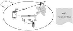
图3是根据本发明实施例的从间接中继链路到直接蜂窝链路的示范性gNB内路径切换的场景。Fig. 3 is a scenario of an exemplary intra-gNB path switch from an indirect relay link to a direct cellular link according to an embodiment of the present invention.
图4是根据本发明实施例的从直接蜂窝链路到间接中继链路的示范性gNB内路径切换的场景。Fig. 4 is a scenario of an exemplary intra-gNB path switch from a direct cellular link to an indirect relay link according to an embodiment of the present invention.
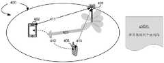
图5是根据本发明实施例的从间接中继链路到与不同gNB之间直接蜂窝链路的示范性gNB间路径切换的场景。Fig. 5 is a scenario of an exemplary inter-gNB path handover from an indirect relay link to a direct cellular link with a different gNB according to an embodiment of the present invention.
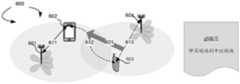
图6是根据本发明实施例的从直接蜂窝链路到与不同gNB之间间接中继链路的示范性gNB间路径切换的场景。Fig. 6 is a scenario of an exemplary inter-gNB path handover from a direct cellular link to an indirect relay link with a different gNB according to an embodiment of the present invention.
图7是根据本发明实施例的从间接中继链路到直接蜂窝链路的gNB内路径切换的示范性流程图。Fig. 7 is an exemplary flowchart of intra-gNB path switching from an indirect relay link to a direct cellular link according to an embodiment of the present invention.
图8是根据本发明实施例的从直接蜂窝链路到间接中继链路的gNB内路径切换的示范性流程图。Fig. 8 is an exemplary flowchart of intra-gNB path switching from direct cellular link to indirect relay link according to an embodiment of the present invention.
图9是根据本发明实施例的从间接中继链路到与不同gNB之间的直接蜂窝链路的gNB间路径切换的示范性流程图。Fig. 9 is an exemplary flowchart of inter-gNB path switching from an indirect relay link to a direct cellular link with a different gNB according to an embodiment of the present invention.
图10是根据本发明实施例的从直接蜂窝链路到与不同gNB之间的间接中继链路的gNB间路径切换的示范性流程图。Fig. 10 is an exemplary flowchart of inter-gNB path switching from a direct cellular link to an indirect relay link with a different gNB according to an embodiment of the present invention.
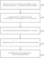
图11是根据本发明实施例的具有服务连续性的从间接中继链路到直接Uu链路的路径切换的示范性流程图。FIG. 11 is an exemplary flowchart of path switching from an indirect relay link to a direct Uu link with service continuity according to an embodiment of the present invention.
图12是根据本发明实施例的具有服务连续性的从直接Uu链路到间接中继链路的路径切换的示范性流程图。FIG. 12 is an exemplary flowchart of path switching from a direct Uu link to an indirect relay link with service continuity according to an embodiment of the present invention.
具体实施方式Detailed ways
现详细给出关于本发明的一些实施例作为参考,其示例在附图中描述。Reference will now be made in detail to some embodiments of the invention, examples of which are illustrated in the accompanying drawings.
图1是根据本发明实施例的用于基于路径切换的服务连续性的示范性NR无线网络的系统示意图。NR无线系统100包括形成分布在地理区域上的网络的一个或多个固定基本设施单元。基本单元也可以被称为接入点、接入终端、基站、节点B、演进节点B(eNode-B)、gNB或本领域中使用的其他术语。网络可以是同构网络也可以是异构网络,可以采用相同或不同频率进行部署。gNB 101、gNB 102和gNB 103是NR网络中的基站,其服务区域可以相互重叠,也可以不重叠。诸如131、132和133之类的回传连接(backhaul connection)连接诸如gNB 101、102和103之类的非共置(non-co-located)接收基本单元。这些回传连接可以是理想的,也可以是非理想的。gNB 101通过Xnr接口131与gNB 102连接,并通过Xnr接口132与gNB 103连接。gNB 102通过Xnr接口133与gNB 103连接。FIG. 1 is a system diagram of an exemplary NR wireless network for service continuity based on path switching according to an embodiment of the present invention. The NR
NR无线网络100还包括多个通信装置或移动站,如用户设备(user equipment,UE)111、112、113、117、118、121、122、123和128。NR无线网络100中的通信装置或移动站还可被称为移动台、移动终端、移动电话、智能电话、可穿戴设备、IoT设备、平板电脑、笔记本电脑或本领域中使用的其他术语。它还可指代车辆中具有无线连接的装置,如移动装置117、118和128。无线网络100中的示范性移动装置具有SL功能。移动装置可与一个或多个基站(如gNB 101、102和103)建立一个或多个连接。移动装置(如移动装置117)还可能在其接入链路与基站断开连接,但可通过基于L2的SL中继与另外的一个或多个移动站或者一个或多个基站之间发送和接收数据封包。The NR
数据封包可由一个或多个中继UE基于L2报头中的信息转发。远程UE 111和gNB103通过与中继UE 121的基于层2的SL中继,形成端到端(end-to-end)路径181。端到端路径181包括gNB 103和中继UE 121之间的接入链路135,以及远程UE 111和中继UE 121之间的侧链路171。在一实施例中,远程UE 111还具有与gNB 103的直接接入链路138。在其他实施例中,基于L2的侧链路中继是具有多个中继UE的多跳(multi-hop)中继。远程UE 112和gNB102通过与中继UE 122和另一个中继UE 123的基于L2的SL中继,形成端到端路径182。端到端路径182包括gNB 102和中继UE 122之间的接入链路136、中继UE 122和中继UE 123之间的侧链路172,以及远程UE 112和中继UE 123之间的侧链路173。在又一实施例中,中继移动装置配置有多个远程移动装置或多个端节点移动装置。具有与gNB 101之间接入链路137的中继UE 128分别通过侧链路175和176配置有两个远程UE 117和118。在一实施例中,基于L2的UE到网络侧链路中继包括一个或多个为网络覆盖范围之外UE的远程UE,例如远程UE117。可建立不同链路用于图示中继路径。接入链路是基站(如gNB)与移动装置(如UE)之间的链路,上述UE可以是远程UE或中继UE。接入链路包括基站和移动装置之间的上行链路(uplink,UL)和下行链路(downlink,DL)。接入链路的接口为NR Uu接口。在一实施例中,远程UE也与基站建立接入链路,如远程UE 111与gNB 103建立接入链路138。侧链路是两个移动装置之间的链路,并使用PC5接口。侧链路可以是远程UE/端节点UE与中继UE之间的链路,也可以是多跳中继中两个中继移动装置/UE之间的链路。用于中继路径的端到端链路可以是用于UE到UE中继的两个端节点移动装置之间的链路,也可以是UE到网络中继的基站与移动装置之间的链路。Xn链路是两个基站(如使用Xn接口的gNB)之间的回传链路。在一实施例中,候选中继UE信息经由Xn链路被发送到基站。The data packet may be forwarded by one or more relaying UEs based on the information in the L2 header. The remote UE 111 and the gNB 103 form an end-to-
在一示范例中,对于UE到网络的连接来说,直接Uu/蜂窝连接与通过侧链路中继的间接链路之间的路径切换需在服务连续的前提下执行的。举例来说,UE 121通过侧链路中继经由路径181与gNB 103连接,其中路径181包括侧链路171和Uu直接链路138。在一个或多个预定义触发事件发生时可能触发路径切换。UE 121在保持服务连续性的前提下执行到Uu直接链路135的路径切换。在不同的场景中,当UE 121通过直接链路135与gNB 103连接时,它执行路径切换以切换到通过UE 111的具有侧链路中继的中继路径181的路径切换。路径切换是在具有服务连续性的情况下执行的。In one example, for UE-to-network connection, path switching between direct Uu/cellular connection and indirect link relayed via side link is performed under the premise of service continuity. For example,
图1进一步示出了用于基于L2的侧链路中继的适配处理的基站和移动装置/UE的简化方块示意图。gNB 103具有天线156,用来发送和接收无线电信号。耦接于上述天线的RF收发器电路153从天线156接收RF信号,将RF信号转换为基带信号,并将基带信号发送到处理器152。RF收发器153还将从处理器152接收到的基带信号转换为RF信号,并发送到天线156。处理器152处理接收到的基带信号,并调用不同的功能模块来执行gNB 103中的功能特性。存储器151存储程序指令和数据154以控制gNB 103的操作。gNB 103还包括一组控制模块155,用来执行功能任务以与移动站通信。Fig. 1 further shows a simplified block schematic diagram of a base station and a mobile device/UE for an adaptation process for L2-based sidelink relay. The gNB 103 has an
图1还示出了UE(如中继UE 121或远程UE 111)的简化方块示意图。UE具有天线165,用于发送和接收无线电信号。耦接于上述天线的RF收发器电路163从天线165接收RF信号,将RF信号转换为基带信号,并将基带信号发送到处理器162。在一实施例中,RF收发器可包括两个RF模块(未示出)。第一RF模块用于高频(high frequency,HF)发送和接收;另一RF模块不同于HF收发器,用于不同频段的发送和接收。RF收发器163还将从处理器162接收到的基带信号转换为RF信号,并发送到天线165。处理器162处理接收到的基带信号,并调用不同的功能模块来执行UE中的功能特性。存储器161存储程序指令和数据164以控制UE的操作。天线165向gNB 103的天线156发送上行链路传送,并从gNB 103的天线156接收下行链路传送。FIG. 1 also shows a simplified block diagram of a UE such as
UE还包括一组控制模块,用于执行功能任务。这些控制模块可通过电路、软件、固件或上述的组合实现。原始路径处理器191通过NR无线网络中的侧链路中继路径与源gNB建立间接连接,其中侧链路中继路径具有至少一个服务中继UE通过服务侧链路与UE连接。配置接收器192从源gNB接收包括用于测量的频率列表的测量配置,其中频率列表包括一个或多个Uu直接链路以及一个或多个PC5侧链路。响应处理器193基于接收到的测量配置在检测到预定义路径切换触发事件时发送测量报告。命令接收器194从源gNB接收指示从侧链路中继路径切换到目标直接Uu链路的路径切换消息。路径切换处理器195基于路径切换消息建立目标直接Uu链路的连接,以执行具有服务连续性的路径切换。The UE also includes a set of control modules for performing functional tasks. These control modules can be implemented by circuits, software, firmware or a combination of the above. The
图2是根据本发明实施例的具有NR无线电接口栈的集中化上层的示范性NR无线系统示意图。gNB节点的中央单元(central unit,CU)和分布式单元(distributed unit,DU)之间可能有不同的协议划分选择。gNB节点的CU和DU之间的功能划分可能取决于传输层。由于较高的协议层在带宽、延迟、同步和抖动方面对传输层的性能要求较低,gNB节点的CU和DU之间的低性能传输可以使能NR无线电栈的高协议层在CU中得到支持。在一实施例中,服务数据适配协议(service data adaptation protocol,SDAP)和分组数据汇聚协议(packet data convergence protocol,PDCP)层位于CU,而无线电链路控制(radio linkcontrol,RLC)、介质访问控制(media access control,MAC)和物理(physical,PHY)层位于DU。核心单元(core unit)201与具有gNB上层(upper layer)252的中央单元211连接。在一实施例250中,gNB上层252包括PDCP层和可选的SDAP层。中央单元211与分布式单元221、222和223连接,其中分布式单元221、222和223分别对应于小区231、232和233。分布式单元221、222和223包括gNB下层(lower layer)251。在一实施例中,gNB下层251包括PHY、MAC和RLC层。在另一实施例260中,每个gNB具有包括SDAP、PDCP、RLC、MAC和PHY层的协议栈261。2 is a schematic diagram of an exemplary NR radio system with a centralized upper layer of the NR radio interface stack according to an embodiment of the present invention. There may be different protocol division options between the central unit (CU) and the distributed unit (DU) of the gNB node. The functional division between CU and DU of a gNB node may depend on the transport layer. Since the higher protocol layers have lower performance requirements on the transport layer in terms of bandwidth, latency, synchronization and jitter, the low-performance transmission between the CU and DU of the gNB node can enable the higher protocol layers of the NR radio stack to be obtained in the CU. support. In one embodiment, the service data adaptation protocol (service data adaptation protocol, SDAP) and packet data convergence protocol (packet data convergence protocol, PDCP) layers are located in the CU, and the radio link control (radio link control, RLC), media access The control (media access control, MAC) and physical (physical, PHY) layers are located in the DU. A
基于UE到网络中继的通信需要在直接Uu路径和通过UE到网络中继的间接Uu路径之间进行通信路径切换期间保持服务的连续性。具有侧链路中继的UE到网络中继路径切换有着不同的场景。UE-to-network relay-based communication requires service continuity during communication path switching between direct Uu path and indirect Uu path via UE-to-network relay. There are different scenarios for UE-to-network relay path handover with sidelink relay.
图3是根据本发明实施例的从间接中继链路到直接蜂窝链路的示范性gNB内(intra-gNB)路径切换的场景。UE 303通过中继UE 302经由间接链路连接到gNB 301。间接链路中继路径包括UE 303与中继UE 302之间的侧链路312,以及中继UE 302与gNB 301之间的Uu链路311。在一实施例中,UE 303接收测量报告并对中继链路和直接Uu链路进行测量。UE 303配置有触发事件以发送测量报告。网络在接收到来自UE 303的测量报告后,确定发起路径切换。UE 303接收路径切换命令。在步骤321,UE将路径切换到与gNB 301之间的Uu直接链路313。Fig. 3 is a scenario of an exemplary intra-gNB (intra-gNB) path handover from an indirect relay link to a direct cellular link according to an embodiment of the present invention.
图4是根据本发明实施例的从直接蜂窝链路到间接中继链路的示范性gNB内路径切换的场景。UE 403经由直接Uu链路413连接到gNB 401。在一实施例中,UE 403从网络接收测量报告配置,包括与gNB之间Uu链路以及与中继UE之间侧链路两者的频率列表。UE 403与中继UE 402执行PC5-S发现。在检测到预定义触发事件时,UE 403向网络发送测量报告。网络决定进行路径切换,UE 403从网络接收路径切换命令。在步骤421,UE 403将路径切换为与gNB 401之间的间接链路。间接链路包括UE 403与中继UE 402之间的侧链路412,以及中继UE 402与NB 401之间的Uu直接链路411。在另一实施例中,UE 403从gNB 401接收中继发现命令并与中继UE 402执行PC5-S发现。UE 403向gNB 401发送侧链路UE信息(sidelink UEInformation,SUI)消息。网络决定执行路径切换,UE 403从网络接收路径切换命令。在步骤421,UE 403将路径切换为与gNB 401之间的间接链路。间接链路包括UE 403和中继UE 402之间的侧链路412,以及中继UE 402与gNB 401之间的Uu直接链路411。Fig. 4 is a scenario of an exemplary intra-gNB path switch from a direct cellular link to an indirect relay link according to an embodiment of the present invention.
图5是根据本发明实施例的从间接中继链路到与不同gNB之间直接蜂窝链路的示范性gNB间(inter-gNB)路径切换的场景。UE 503通过中继UE 502经由间接链路连接到gNB501。间接链路中继路径包括UE 503与中继UE 502之间的侧链路512,以及中继UE 502与gNB501之间的Uu链路511。在一实施例中,UE 503接收测量报告并在中继链路和直接Uu链路(包括与不同gNB 504之间的Uu链路)上执行测量。UE 503配置有触发事件用来发送测量报告。网络在接收到来自UE 503的测量报告后,决定发起路径切换。UE 503接收路径切换命令。在步骤521,UE将路径切换到与gNB 504之间的Uu直接链路513。Fig. 5 is a scenario of an exemplary inter-gNB (inter-gNB) path handover from an indirect relay link to a direct cellular link with a different gNB according to an embodiment of the present invention.
图6是根据本发明实施例的从直接蜂窝链路到与不同gNB之间间接中继链路的示范性gNB间路径切换的场景。UE 603经由直接Uu链路613连接到gNB 604。在一实施例中,UE603从网络接收测量报告配置,包括与gNB之间Uu链路和与中继UE之间侧链路两者的频率列表。UE 603与中继UE 602执行PC5-S发现。在检测到预定义触发事件时,UE 603向网络发送测量报告。网络决定进行路径切换,UE 603从网络接收路径切换命令。在步骤621,UE 603将路径切换为经由中继UE 602的与不同gNB 601之间的间接链路。间接链路包括UE 603与中继UE 602之间的侧链路612,以及中继UE 602与gNB 601之间的Uu直接链路611。在另一实施例中,UE 603从gNB 604接收中继发现命令,并与中继UE 602执行PC5-S发现。UE 603向gNB604发送SUI消息,网络决定执行路径切换。UE 603从网络接收路径切换命令。在步骤621,UE603将路径切换为经由中继UE 602与不同gNB 601之间的间接链路。间接链路包括UE 603与中继UE 602之间的侧链路612,以及中继UE 602与gNB 601之间的Uu直接链路611。Fig. 6 is a scenario of an exemplary inter-gNB path handover from a direct cellular link to an indirect relay link with a different gNB according to an embodiment of the present invention.
在一示范例中,用于路径切换的侧链路中继是L2 UE到网络中继。当中继UE与远程UE建立PC5单播链路时,中继UE与远程UE进行关联以进行业务中继。远程UE-中继UE关联或中继UE-远程UE关联得以形成。一对UE身份(如UE L2 ID、UE ID索引或UE ID的截短版本(truncated version))可指示这种类型的关联。In one example, the sidelink relay used for path switching is an L2 UE-to-network relay. When the relay UE establishes a PC5 unicast link with the remote UE, the relay UE associates with the remote UE for service relay. A remote UE-relay UE association or a relay UE-remote UE association is formed. A pair of UE identities such as a UE L2 ID, a UE ID index or a truncated version of a UE ID may indicate this type of association.
图7是根据本发明实施例的从间接中继链路到直接蜂窝链路的gNB内路径切换的示范性流程图。在步骤711,在具有核心网(core network,CN)实体704的NR无线网络中,远程UE 701与gNB 703之间存在通过中继UE 702的正在进行的间接业务。在步骤721,gNB 703通过中继UE 702经由中继链路发送测量配置到远程UE 701,其中测量配置包括要为蜂窝链路以及/或者中继链路测量的频率列表。在步骤722,远程UE 701经由UE到网络中继向gNB703发送Uu RRC消息(如测量报告)。测量报告的发送由一个或多个触发事件触发。在一实施例中,触发事件由步骤721的测量报告配置来配置。在另一实施例中,新A3链路事件被定义为“蜂窝质量(Uu)比服务中继UE(PC5)高出一偏移值(offset better)”。UE 701基于其测量结果确定是否满足一个或多个触发事件。在步骤731,基于接收到的RRC消息、测量报告,gNB703决定将远程UE 701从UE到网络中继切换为连接至服务gNB 703。Fig. 7 is an exemplary flowchart of intra-gNB path switching from an indirect relay link to a direct cellular link according to an embodiment of the present invention. In step 711 , in an NR wireless network with a core network (core network, CN)
在步骤751,gNB 703通过UE到网络中继向远程UE 701发送RRC重配置(RRCReconfiguration)消息,以配置远程UE 701与gNB 703之间链路的PHY、MAC、RLC、PDCP和SDAP层。在另一实施例中,RRC重配置消息仅配置远程UE 701与gNB 703之间链路的PHY、MAC和RLC层。从L2中继的角度来看,远程UE的PDCP和SDAP层终止于远程UE 701与gNB 703,路径切换后PDCP/SDAP配置没有变化。在步骤752,远程UE 701发送重新配置完成(RRCReconfigurationComplete)消息给gNB 703。在步骤761,Uu接口(即直接路径)可承载远程UE 701和gNB 703之间的业务。In
在步骤771,gNB 703与CN 704(如接入和移动性管理功能(access and mobilitymanagement function,AMF))交换信令以更新UE上下文(context)。假定gNB和AMF(中继UE的AMF)都将远程UE-中继UE关联存储在中继UE上下文中。AMF随着关联状态的变化而更新,即由于PC5到Uu的切换,远程UE-中继UE关联可释放。gNB 703与AMF一起对远程UE-中继UE关联进行同步更改。远程UE-中继UE关联的状态可发送给远程UE的AMF,以便从移动性的角度跟踪UE。In step 771,
在步骤781,gNB 703向中继UE 702发送RRC重配置消息来配置PHY、MAC、RLC、PDCP、SDAP层或上述任何组合,以用于中继UE和基站之间的链路。在一实施例中,RRC重配置消息仅配置专用无线电承载(dedicated radio bearer,DRB)的释放列表,例如IERadioBearerConfig或RelayRadioBearerConfig中仅包含DRB-ToReleaseList。在另一实施例中,RRC重配置消息仅指示远程UE-中继UE关联的索引,其隐含意味着释放为上述远程UE-中继UE关联建立的所有用于中继的DRB。举例来说,RRC重配置消息所包含的IERadioBearerConfig或RelayRadioBearerConfig中的DRB-ToReleaseList仅包含远程UE-中继UE关联索引。在步骤782,当重配置完成时,中继UE 702向基站703发送RRC重配置完成消息。在步骤791,通过PC5-S信令释放远程UE 701与中继UE 702之间的PC5单播链路。远程UE701与中继UE 702之间的PC5 RRC连接被自动释放。In step 781, the
图8是根据本发明实施例的从直接蜂窝链路到间接中继链路的gNB内路径切换的示范性流程图。在步骤811,在具有CN实体704的NR无线网络中,远程UE 801与gNB 803之间存在正在进行的直接业务。在步骤812,中继UE 802与远程UE的服务gNB 803连接。在步骤813,中继UE 802通过RRC消息(如SidelinkUEInformation)向其服务gNB发送中继指示。其向gNB 803指示中继UE 802可在特定频率列表中提供UE到网络的中继。举例来说,在V2X车队操作中,头节点负责转发成员节点的Uu业务。在中继UE之前分配过远程UE的L2 ID的场景下,中继UE可将一个或多个远程UE的L2 UE ID包括在RRC消息(如SidelinkUEInformation)中,以告知基站作为中继UE可建立中继链路的一个或多个远程UE。Fig. 8 is an exemplary flowchart of intra-gNB path switching from direct cellular link to indirect relay link according to an embodiment of the present invention. In step 811 , there is ongoing direct traffic between
在一实施例中,在步骤821,gNB 803向远程UE 801发送测量配置,包括要针对蜂窝链路以及/或者中继链路进行测量的频率列表。在另一实施例中,在步骤822中,gNB 803向远程UE 801发送Uu RRC消息(如中继发现命令)来代替测量配置。这可由远程UE先前发送给基站的指示触发,其中上述指示表示其有兴趣在特定频率列表中作为中继UE在UE到网络中继中操作。这也可以由中继UE在步骤813发送给服务gNB 803的中继指示触发。中继发现命令的RRC消息包括中继UE身份信息(如L2 ID),这有助于远程UE 801找到正确的中继UE进行发现。在另一实施例中,中继发现命令的RRC消息携带测量配置消息的内容。In one embodiment, in step 821, the
在步骤823,远程UE 801通过PC5-S信令发现中继UE 802并选择中继UE 802。所触发的PC5-S中继发现基于步骤821测量配置中所配置的测量事件,或基于系统信息所配置的标准,或满足中继选择的(预)配置。步骤821和822可配置NR现有测量事件。在另一实施例中,可配置新测量事件或标准。上述新事件或标准可定义为“中继UE质量(PC5)比服务小区(Uu)高出一偏移值”、“中继UE质量(PC5)高于一绝对阈值(预定义阈值)”或“中继UE质量(PC5)比一绝对阈值高出一偏移值”。远程UE 801在选择中继802之前评估每个测量结果的事件或标准。如果在步骤822向远程UE 801提供中继UE L2 ID,则远程UE将上述ID放入PC5-S发现消息(如广播直接通信请求)中,以便与正确的中继UE建立PC5单播链路。预期效果是只有正确的中继UE向远程UE 801响应直接通信响应。作为附加选项,可将远程UE自己的L2ID放入PC5-S消息(如广播直接通信请求)中用于发现目的,以便允许中继UE根据上层或应用层对所接收直接通信请求的限制来确定其响应。在步骤824,远程UE向基站发送Uu RRC消息(如测量报告)。在另一实施例中,在步骤825,远程UE 801向gNB 803发送SUI消息。中继UE身份信息(如中继UE ID)被报告给gNB 803。在步骤831中,基于接收到的RRC消息,gNB 803决定远程UE 801的路径切换,即从服务gNB 803切换到UE到网络中继。In
在步骤851,gNB 803向远程UE 801发送RRC重配置消息。gNB 803指示远程UE 801从直接Uu PHY无线电资源切换,并为基于Uu的无线电承载释放相应的RLC实体和MAC实体。基于Uu的无线电承载的SDAP和PDCP配置保持不变。gNB 803指示远程UE 801与中继802建立单播链路。在步骤852,远程UE 801与中继UE 802之间建立PC5-S链路。在一实施例中,在远程UE801与中继UE 802之间的单播链路建立之后激活安全。在步骤853,远程UE 801向gNB802发送RRC重配置完成消息。In
在步骤881,gNB 803向中继UE 802发送RRC重配置消息以配置PHY、MAC、RLC、PDCP、SDAP层或上述任意组合,用于中继UE 802与gNB 803之间的中继承载。现有的无线电承载配置(RadioBearerConfig)结构或新定义的中继无线电承载配置(RelayRadioBearerConfig)结构用于保存所有用于中继的无线电承载(即RB)配置。在一实施例中,中继UE 802服务于多个远程UE。中继UE 803及其服务基站gNB 803都维护多个中继UE-远程UE关联。服务gNB可为中继UE的每个中继UE-远程UE关联分配一个索引。如果使用既有RadioBearerConfig结构来表示中继RB配置,则需要附加字段(如中继RB指示符、每个中继UE-远程UE关联的索引、远程UE ID)来区分中继RB和常规RB,并区分每个中继UE-远程UE关联的不同RB。如果使用新定义的RelayRadioBearerConfig结构来表示中继RB配置,则需要额外的字段(如每个中继UE-远程UE关联的索引、远程UE ID)来区分每个中继UE-远程UE关联的不同RB。在一实施例中,用于中继RB的SDAP配置(SDAP-config)在RRC重配置、中继RB建立期间被省略。在进行中继关联时,gNB将端到端RB映射到中继UE与gNB之间的间接RB(即中继RB),并且在承载映射之后不再应用上述流程概念。具体来说,当多个端到端RB映射到一个间接RB时,一个间接RB中的多个SDAP配置并不适用。中继RB配置包括PDCP配置(PDCP-config),而目前DRB设置所必须的IE cnAssociation可被省略。在一实施例中,用于配置中继RB的既有RadioBearerConfig结构或新定义的RelayRadioBearerConfig结构可包括以下字段之一或任意组合:In step 881 , the
·中继RB指示符· Relay RB indicator
·专用无线电承载识别符(drb-Identity)Dedicated radio bearer identifier (drb-Identity)
·分组数据汇聚协议配置(pdcp-Config)· Packet Data Convergence Protocol Configuration (pdcp-Config)
·中继UE-远程UE关联索引Relay UE-remote UE association index
·中继UE ID· Relay UE ID
·远程UE ID·Remote UE ID
·映射的端到端drb-Identity· Mapped end-to-end drb-Identity
·中继侧链路的L2 RLC信道ID· L2 RLC channel ID of the link on the relay side
·L2 RLC中继信道的逻辑信道IDThe logical channel ID of the L2 RLC trunk channel
在步骤882,在从gNB 803接收到RRC重配置消息时,中继UE 802通过发送L2 RCL信道建立请求消息,发起L2 RLC信道建立过程以在中继UE 802和远程UE 801之间进行中继。上述RRC消息包括一个或一组RLC中继信道配置。每个中继信道配置包括相关端到端Uu无线电承载索引(如ServedRadioBearer)、RLC层索引(如sl-RLC-BearerConfigIndex)、RLC配置(如sl-RLC-Config)、MAC逻辑信道配置(如sl-MAC-LogicalChannelConfig)、侧链路逻辑信道ID、中继信道ID、每个相关端到端Uu无线电承载内的QoS流的QoS配置文件(profile),或者它们的任意组合。RLC配置包括RLC模式、SN长度等。在另一实施例中,中继UE-远程UE关联也包含在上述消息中,以指示中继信道是为中继UE-远程UE关联建立的。在一实施例中,端到端无线电承载ID的列表被包括在每个中继信道配置中用于每个中继信道,它用于通知远程UE承载特定端到端无线电承载的RLC信道。在步骤882,远程UE 801向中继UE 802发送PC5RRC消息,如L2 RLC信道建立完成,以确认用于中继的L2 RLC信道的建立。在另一实施例中,步骤882由步骤851触发。L2 RLC信道建立请求由远程UE 801发送到中继UE 802,并且当L2RLC信道建立完成时,中继UE 802向远程UE 801发送L2 RLC信道建立完成的确认。步骤851的RRC重配置消息中可携带用于中继的L2 RLC信道的配置。在步骤884,中继UE 802向gNB803发送RRC重配置完成消息。在步骤891,PC5可以承载远程UE与网络之间的业务。In step 882, upon receiving the RRC reconfiguration message from the
图9是根据本发明实施例的从间接中继链路到与不同gNB之间的直接蜂窝链路的gNB间路径切换的示范性流程图。在步骤911,在具有CN实体905的NR无线网络中,远程UE901与gNB 903之间存在正在进行的通过中继UE 902的间接业务。在步骤921,gNB 903经由中继链路通过中继UE 902发送测量配置给远程UE 901,其中上述测量配置包括要为蜂窝链路和/或中继链路测量的频率列表。在步骤922,远程UE 901经由UE到网络中继向gNB 903发送Uu RRC消息(如测量报告)。测量报告的发送可由一个或多个触发事件触发。在一实施例中,触发事件由步骤921的测量报告配置来配置。在另一实施例中,新A3链路事件被定义为“包括与不同gNB之间Uu链路的蜂窝质量(Uu)比服务中继UE(PC5)高出一偏移值”。UE 901基于测量结果确定是否满足一个或多个触发事件。在步骤931,基于接收到的RRC消息(测量报告),gNB 903决定将远程UE 901从UE到网络中继切换到服务gNB 903。在步骤951,在远程UE901的服务gNB 903决定将远程UE从中继链路切换到蜂窝链路之后,源gNB 903通过Xn接口为远程UE 901向目标gNB 904发起HO请求。在另一实施例中,源gNB通过N2接口向源CN实体905(如源AMF)发起HO请求。源AMF向目标AMF发送HO请求,目标AMF向目标gNB 904发送远程UE 901的HO请求。在步骤951,目标gNB 904通过Xn接口响应HO确认消息。或者,目标gNB 904通过N2接口将HO确认消息的响应发送给目标AMF,由目标AMF向源AMF发送HO确认的响应。源AMF向远程UE 901的源gNB 903发送HO确认。Fig. 9 is an exemplary flowchart of inter-gNB path switching from an indirect relay link to a direct cellular link with a different gNB according to an embodiment of the present invention. In step 911 , in the NR wireless network with
在步骤961,源gNB 903通过RRC重配置消息将切换命令信息传递给远程UE 901,上述信息包括移动性控制信息(mobilitycontrolinfo)。在步骤962,源gNB 903向目标gNB904发送SN状态转换(SN status transfer)。在步骤963,源gNB 903将数据转发给目标gNB904。在步骤964,远程UE 901向目标gNB 904发送RRC重配置完成消息。在步骤965,目标gNB904向AMF(在CN 905中)发送路径切换请求(path switch request)消息以通知UE已经改变小区。路径切换请求还可以更新远程UE的上下文,如AMF中远程UE-中继UE关联的状态。在步骤966,AMF通过路径切换请求确认消息向目标gNB 904确认路径切换消息。在步骤967,目标gNB 904通知源gNB 903释放远程UE 901的UE上下文。在步骤971,远程UE 901与目标gNB904之间的直接Uu接口承载远程UE与网络之间的直接业务。在步骤981,中继UE 902的源gNB(假设在这种场景下远程UE和中继UE具有相同的源gNB)向UE到网络中继UE 902发送RRC重配置消息。在步骤982,中继UE 902发送RRC重配置完成消息给源gNB 903。在步骤991,远程UE 901与中继UE 902之间的PC5单播链路通过PC5-S信令释放。远程UE 901与中继UE 902之间的PC5 RRC连接被自动释放。In
图10是根据本发明实施例的从直接蜂窝链路到与不同gNB之间的间接中继链路的gNB间路径切换的示范性流程图。在步骤1011,在具有CN实体1005的NR无线网络中,远程UE1001与gNB 1003之间存在正在进行的直接业务。在步骤1012,中继UE 1002与目标gNB 1004连接。在步骤1013,中继UE 1002通过RRC消息(如SidelinkUEInformation)向其服务gNB、目标gNB 1004发送中继指示。它向gNB 1004指示中继UE 1002可在某个频率列表中提供UE到网络的中继。Fig. 10 is an exemplary flowchart of inter-gNB path switching from a direct cellular link to an indirect relay link with a different gNB according to an embodiment of the present invention. In step 1011 , there is ongoing direct traffic between
在一实施例中,在步骤1021,gNB 1003向远程UE 1001发送测量配置,包括要针对蜂窝链路和/或中继链路进行测量的频率列表。在另一实施例中,在步骤1022,代替测量配置,gNB 1003向远程UE 1001发送Uu RRC消息,如中继发现命令(relay discoverycommand)。这可以由远程UE先前发送给基站的指示所触发,其中上述指示表示其有兴趣在特定频率列表中作为远程UE通过UE到网络中继进行操作。在另一实施例中,中继发现命令的RRC消息携带测量配置消息的内容。In one embodiment, at step 1021, the
在步骤1023,远程UE 1001执行中继发现和选择。在中继发现阶段,远程UE 1001获取中继UE 1002的目标gNB 1004的服务小区ID。远程UE 1001与中继UE 1002之间的发现由PC5-S信令管理。如果在侧链路通信之前不支持显式中继发现过程,则中继UE 1002在接受来自远程UE 1001的PC5-S直接通信请求(PC5-S direct communication request)时,将gNB 1004的服务小区ID放入PC5-S直接通信响应(PC5-S direct communicationresponse)中。如果显式中继发现过程在侧链路通信之前进行,则中继UE将gNB 1004的服务小区ID放入PC5-S发现通知(发现模式A)或发现响应(发现模式B)中。在一实施例中,远程UE1001与中继UE 1002可将相应的服务小区ID放入为中继发现而交换的PC5-S信令中。在一实施例中,中继UE 1002向服务gNB 1004报告相关远程UE(包括远程UE L2 ID以及远程UE的服务小区ID),以允许基站准备远程UE接入以及/或者与远程UE的源gNB协调。In
在步骤1024,远程UE 1001向源gNB 1003发送Uu RRC消息(如测量报告)。在另一实施例中,在步骤1025,远程UE 1001向gNB 1003发送SUI消息。中继UE信息以及/或者中继UE服务小区ID被报告给目标gNB 1004。中继UE信息包括以下一个或多个元素:中继UE L2 ID、C-RNTI、ShortMAC-I或上述的任意组合。中继UE服务小区ID可包括CGI和/或PCI。在步骤1031,服务gNB 1003决定将远程UE 1001从蜂窝链路切换到中继链路。在步骤1051,源gNB1003发起HO过程。中继UE-远程UE关联包含在HO请求消息中。在步骤1052,源gNB 1003接收HO确认,其中包括中继UE-远程UE关联。在一实施例中,HO请求和HO确认消息中可包括多个中继UE-远程UE关联。In step 1024, the
在步骤1061,源gNB 1003通过包括移动控制信息的RRC重配置消息将切换命令信息传递给远程UE 1001。gNB 1003还指示远程UE 1001与中继UE 1002建立单播链路。在步骤1062,源gNB 1003向目标gNB 1004发送SN状态转换。在步骤1063,源gNB 1003将数据转发到目标gNB 1004。在步骤1064,远程UE 1001与中继UE 1002之间建立PC5-S单播链路。在步骤1065,远程UE 1001向目标gNB 1004发送RRC重配置完成消息。在步骤1071,目标gNB 1004向中继UE 1002发送RRC重配置消息。在步骤1072,中继UE 1002向远程UE 1001发送PC5 RRC消息,如L2 RLC信道建立请求。在步骤1073,远程UE 1001发送PC5 RRC消息(如L2 RLC信道建立完成)给中继UE 1002,以确认建立L2 RLC信道用于中继。在另一实施例中,步骤1072由步骤1061的切换命令触发。远程UE 1001发送L2 RLC信道建立请求给中继UE 1002。中继UE1002向远程UE 1001确认L2 RLC信道建立完成。在本实施例中,步骤1061中的切换命令携带用于中继的L2 RLC信道的配置。在步骤1074,中继UE 1002发送RRC重配置完成消息给目标gNB 1004。在步骤1081,PC5可承载远程UE 1001与网络1005之间的业务。在步骤1082,目标gNB 1004发送路径切换请求消息给AMF(在CN 1005中),以通知UE已更改小区。在步骤1083,作为对路径切换请求的确认,AMF将路径切换请求确认消息发送给目标gNB 1004。在步骤1091,目标gNB 1004通知源gNB 1003释放远程UE 1001的UE上下文。In step 1061, the
图11是根据本发明实施例的具有服务连续性的从间接中继链路到直接Uu链路的路径切换的示范性流程图。在步骤1101,UE通过新无线电无线网络中的侧链路中继路径与源gNB建立间接连接,其中侧链路中继路径具有至少一个服务中继UE通过服务侧链路与UE连接。在步骤1102,UE从源gNB接收包括用于测量的频率列表的测量配置,其中频率列表包括一个或多个Uu直接链路以及一个或多个PC5侧链路。在步骤1103,UE基于接收到的测量配置在检测到预定义路径切换触发事件时发送测量报告。在步骤1104,UE从源gNB接收路径切换消息,指示从侧链路中继路径切换到目标直接Uu链路。在步骤1105,UE基于路径切换消息建立目标直接Uu链路的连接,以执行具有服务连续性的路径切换。FIG. 11 is an exemplary flowchart of path switching from an indirect relay link to a direct Uu link with service continuity according to an embodiment of the present invention. In
图12是根据本发明实施例的具有服务连续性的从直接Uu链路到间接中继链路的路径切换的示范性流程图。在步骤1201,UE通过新无线电无线网络中的源Uu链路与源gNB建立直接连接。在步骤1202,UE从源gNB接收包括一个或多个路径切换触发事件的消息。在步骤1203,UE在检测到至少一个路径切换触发事件时发送响应给源gNB。在步骤1204,UE从源gNB接收路径切换消息,指示从源Uu链路切换到侧链路中继路径。在步骤1205,UE基于路径切换消息与侧链路中继路径中的中继UE建立侧链路,以执行具有服务连续性的路径切换。FIG. 12 is an exemplary flowchart of path switching from a direct Uu link to an indirect relay link with service continuity according to an embodiment of the present invention. In
虽然出于说明目的,已结合特定实施例对本发明进行描述,但本发明并不局限于此。因此,在不脱离权利要求书所述的本发明范围的情况下,可对描述实施例的各个特征实施各种修改、改编和组合。While the invention has been described in connection with specific embodiments for purposes of illustration, the invention is not limited thereto. Accordingly, various modifications, adaptations and combinations may be made to the various features of the described embodiments without departing from the scope of the invention as described in the claims.
Claims (20)
Translated fromChineseApplications Claiming Priority (3)
| Application Number | Priority Date | Filing Date | Title |
|---|---|---|---|
| CNPCT/CN2020/074410 | 2020-02-06 | ||
| PCT/CN2020/074410WO2021155526A1 (en) | 2020-02-06 | 2020-02-06 | Methods and apparatus of path switch based service continuity for ue-to-network relay |
| PCT/CN2021/075459WO2021155839A1 (en) | 2020-02-06 | 2021-02-05 | Methods and apparatus of path switch based service continuity for ue-to-network relay |
Publications (1)
| Publication Number | Publication Date |
|---|---|
| CN115280898Atrue CN115280898A (en) | 2022-11-01 |
Family
ID=77199153
Family Applications (1)
| Application Number | Title | Priority Date | Filing Date |
|---|---|---|---|
| CN202180013386.8APendingCN115280898A (en) | 2020-02-06 | 2021-02-05 | Method and apparatus for service continuity based on path switching from UE to network relay |
Country Status (4)
| Country | Link |
|---|---|
| US (1) | US12408215B2 (en) |
| EP (1) | EP4094543A4 (en) |
| CN (1) | CN115280898A (en) |
| WO (2) | WO2021155526A1 (en) |
Cited By (2)
| Publication number | Priority date | Publication date | Assignee | Title |
|---|---|---|---|---|
| WO2025025033A1 (en)* | 2023-07-29 | 2025-02-06 | Nec Corporation | Methods, devices and medium for communication |
| WO2025107677A1 (en)* | 2024-07-17 | 2025-05-30 | Lenovo (Beijing) Limited | Devices and methods of communication |
Families Citing this family (42)
| Publication number | Priority date | Publication date | Assignee | Title |
|---|---|---|---|---|
| CN111901836A (en)* | 2020-02-13 | 2020-11-06 | 中兴通讯股份有限公司 | Link switching, link switching configuration method, apparatus, communication node, and medium |
| CN113453272B (en)* | 2020-03-25 | 2023-11-10 | 维沃移动通信有限公司 | Handover method and device in secondary link relay architecture |
| US11849382B2 (en)* | 2020-05-28 | 2023-12-19 | Huawei Technologies Co., Ltd. | Methods, apparatus, and systems for fast path switching in wireless communications with user equipment (UE) cooperation |
| CN113891292B (en)* | 2020-07-01 | 2024-01-12 | 华硕电脑股份有限公司 | Method and device for establishing side-link radio bearer for inter-UE relay communication in wireless communication system |
| US20230309155A1 (en)* | 2020-07-31 | 2023-09-28 | Telefonaktiebolaget Lm Ericsson (Publ) | Methods and apparatus for radio connection |
| US20230232472A1 (en)* | 2020-08-06 | 2023-07-20 | Qualcomm Incorporated | Cross-link interference (cli) measurement based sidelink establishment |
| EP4265054A4 (en)* | 2020-12-18 | 2024-09-11 | Lenovo (Beijing) Limited | METHOD AND DEVICE FOR SWITCHING CHANNELS IN A WIRELESS COMMUNICATION SYSTEM |
| KR20240046907A (en)* | 2021-08-19 | 2024-04-11 | 엘지전자 주식회사 | Operation method and device related to PATH SWITCHING and timer of sidelink remote UE in wireless communication system |
| US20240381200A1 (en)* | 2021-09-10 | 2024-11-14 | Lg Electronics Inc. | Operation method related to path switching in sidelink in wireless communication system |
| KR20240054330A (en)* | 2021-09-14 | 2024-04-25 | 엘지전자 주식회사 | Relay UE operation method related to sidelink connection establishment in a wireless communication system |
| EP4183216A4 (en)* | 2021-09-24 | 2023-11-29 | Apple Inc. | MULTIPATH OPERATION IN UE TO NW SIDELINK RELAY |
| WO2023050084A1 (en)* | 2021-09-28 | 2023-04-06 | Oppo广东移动通信有限公司 | Wireless communication method, terminal device, and network device |
| EP4393205A4 (en)* | 2021-10-08 | 2025-01-15 | ZTE Corporation | A method for ue communication path switch based on policy |
| CN116112991A (en)* | 2021-11-10 | 2023-05-12 | 中国移动通信有限公司研究院 | A processing method, device and computer-readable storage medium |
| US20230142957A1 (en)* | 2021-11-11 | 2023-05-11 | Qualcomm Incorporated | Session offloading for l2 ue-to-network relay architecture |
| WO2023096418A1 (en)* | 2021-11-26 | 2023-06-01 | 엘지전자 주식회사 | Operating method related to rrc reconfiguration of relay ue in wireless communication system |
| CN116193637A (en)* | 2021-11-26 | 2023-05-30 | 华硕电脑股份有限公司 | Method and apparatus for remote user equipment to perform direct to indirect path switching |
| WO2023108534A1 (en)* | 2021-12-16 | 2023-06-22 | Mediatek Singapore Pte. Ltd. | Methods and apparatus of sidelink relay based data transmission with multiple paths |
| KR20240125916A (en)* | 2021-12-17 | 2024-08-20 | 지티이 코포레이션 | Methods, devices, and computer program products for wireless communication |
| CA3239370A1 (en)* | 2022-01-04 | 2023-07-13 | Lianhai WU | Method and apparatus for handover |
| CN116419345A (en)* | 2022-01-05 | 2023-07-11 | 中国移动通信有限公司研究院 | Mobility management method, device, communication device and readable storage medium |
| GB2616267A (en)* | 2022-03-01 | 2023-09-06 | Canon Kk | Signalling a link issue in a sidelink relay system |
| KR20230138857A (en)* | 2022-03-24 | 2023-10-05 | 엘지전자 주식회사 | Sidelink Communication Relay Method and Apparatus for the Same |
| WO2023193240A1 (en)* | 2022-04-08 | 2023-10-12 | Lenovo (Beijing) Limited | Methods and apparatuses for a handover preparation in a l2 u2n relay case |
| US20250310838A1 (en)* | 2022-04-08 | 2025-10-02 | Lenovo (Beijing) Limited | Methods and apparatuses for switching to a relay ue in an rrc idle or inactive state |
| WO2023216118A1 (en)* | 2022-05-10 | 2023-11-16 | Zte Corporation | Path switch for ue-to-ue relay communication |
| CN117177287A (en)* | 2022-05-25 | 2023-12-05 | 维沃移动通信有限公司 | Measurement report reporting methods, devices, terminals and network-side equipment |
| EP4557833A4 (en)* | 2022-07-14 | 2025-08-20 | Beijing Xiaomi Mobile Software Co Ltd | Switching method and apparatus |
| AU2022471961A1 (en)* | 2022-07-27 | 2024-08-29 | Lenovo (Beijing) Limited | Method and apparatus for a connection handling mechanism in a l2 u2n relay case |
| EP4570029A1 (en)* | 2022-08-08 | 2025-06-18 | ZTE Corporation | Techniques for sidelink wireless communication |
| EP4569906A1 (en)* | 2022-08-08 | 2025-06-18 | LG Electronics Inc. | Method and apparatus for transmitting/receiving wireless signal in wireless communication system |
| WO2024035101A1 (en)* | 2022-08-09 | 2024-02-15 | 엘지전자 주식회사 | Operation method of remote ue related to triggering of measurement reporting at indirect-to-indirect path switching in wireless communication system |
| CN119895946A (en)* | 2022-09-19 | 2025-04-25 | Lg电子株式会社 | Method of operation in a wireless communication system relating to cell change in multipath relay |
| CN120035966A (en)* | 2022-10-11 | 2025-05-23 | 上海诺基亚贝尔股份有限公司 | Switch Enhancement |
| WO2024077600A1 (en)* | 2022-10-14 | 2024-04-18 | Zte Corporation | Systems and methods for device-to-device communications |
| CN120051972A (en)* | 2022-10-14 | 2025-05-27 | 上海诺基亚贝尔股份有限公司 | Fast indirect path establishment for side link user equipment to network relay |
| CN117998442A (en)* | 2022-11-02 | 2024-05-07 | 北京三星通信技术研究有限公司 | Method performed by a first user equipment or a first network node and corresponding device |
| WO2024092657A1 (en)* | 2022-11-03 | 2024-05-10 | Nec Corporation | Method, device and computer storage medium of communication |
| CN118215085A (en)* | 2022-12-16 | 2024-06-18 | 夏普株式会社 | Method executed by user equipment and user equipment |
| WO2024163702A1 (en)* | 2023-02-02 | 2024-08-08 | Interdigital Patent Holdings, Inc. | Conditional path switching utilizing a remote wireless transmit/receive unit |
| WO2024167264A1 (en)* | 2023-02-06 | 2024-08-15 | 엘지전자 주식회사 | Operating method of relay ue, which is related to handover of relay ue in multi-path relay, in wireless communication system |
| WO2024094228A1 (en)* | 2023-12-19 | 2024-05-10 | Lenovo (Beijing) Limited | Indirect path failure procedure in multi-path |
Citations (7)
| Publication number | Priority date | Publication date | Assignee | Title |
|---|---|---|---|---|
| CN106559443A (en)* | 2015-09-25 | 2017-04-05 | 中兴通讯股份有限公司 | The system of selection of car networking V2X service transmission path and device |
| US20170150490A1 (en)* | 2015-11-19 | 2017-05-25 | Asustek Computer Inc. | Method and apparatus for switching communication interface in a wireless communication system |
| US20180213577A1 (en)* | 2015-07-23 | 2018-07-26 | Intel IP Corporation | Layer 2 relay protocols and mobility relay method |
| CN108631917A (en)* | 2017-03-24 | 2018-10-09 | 中兴通讯股份有限公司 | A kind of information transferring method and device |
| CN109429373A (en)* | 2017-06-23 | 2019-03-05 | 华为技术有限公司 | Communication pattern switching method and network side equipment and terminal device |
| US20190313315A1 (en)* | 2017-03-23 | 2019-10-10 | Sony Corporation | Electronic apparatus for wireless communication and wireless communication method |
| CN110546994A (en)* | 2017-06-06 | 2019-12-06 | 摩托罗拉移动有限责任公司 | Switching communication modes (direct and indirect user access) |
Family Cites Families (9)
| Publication number | Priority date | Publication date | Assignee | Title |
|---|---|---|---|---|
| US10499272B2 (en)* | 2015-08-11 | 2019-12-03 | Intel Corporation | Measurement for device-to-device (D2D) communication |
| JP6623802B2 (en)* | 2016-02-04 | 2019-12-25 | ソニー株式会社 | User terminal, communication device and method |
| WO2020088655A1 (en)* | 2018-11-02 | 2020-05-07 | FG Innovation Company Limited | Sidelink measurement reporting in next generation wireless networks |
| US11304180B2 (en)* | 2019-03-28 | 2022-04-12 | Samsung Electronics Co., Ltd | Method and device of resource allocation for sidelink transmission in wireless communication system |
| US11659551B2 (en)* | 2019-04-02 | 2023-05-23 | Huawei Technologies Co., Ltd. | Higher layer assisted resource configuration for sidelink configured grant transmission |
| CA3080047A1 (en)* | 2019-05-02 | 2020-11-02 | Comcast Cable Communications, Llc | Sidelink congestion control |
| US11546937B2 (en)* | 2019-11-08 | 2023-01-03 | Huawei Technologies Co., Ltd. | System and method for reservation and resource selection for sidelink communication |
| WO2021097808A1 (en)* | 2019-11-22 | 2021-05-27 | Mediatek Singapore Pte. Ltd. | Methods and apparatus of adaptation handling for sidelink relay |
| MX2023001664A (en)* | 2020-08-10 | 2023-03-08 | Lenovo Singapore Pte Ltd | Sidelink angular-based and sl rrm-based positioning. |
- 2020
- 2020-02-06WOPCT/CN2020/074410patent/WO2021155526A1/ennot_activeCeased
- 2021
- 2021-02-05WOPCT/CN2021/075459patent/WO2021155839A1/ennot_activeCeased
- 2021-02-05CNCN202180013386.8Apatent/CN115280898A/enactivePending
- 2021-02-05EPEP21750595.7Apatent/EP4094543A4/enactivePending
- 2022
- 2022-08-03USUS17/817,298patent/US12408215B2/enactiveActive
Patent Citations (7)
| Publication number | Priority date | Publication date | Assignee | Title |
|---|---|---|---|---|
| US20180213577A1 (en)* | 2015-07-23 | 2018-07-26 | Intel IP Corporation | Layer 2 relay protocols and mobility relay method |
| CN106559443A (en)* | 2015-09-25 | 2017-04-05 | 中兴通讯股份有限公司 | The system of selection of car networking V2X service transmission path and device |
| US20170150490A1 (en)* | 2015-11-19 | 2017-05-25 | Asustek Computer Inc. | Method and apparatus for switching communication interface in a wireless communication system |
| US20190313315A1 (en)* | 2017-03-23 | 2019-10-10 | Sony Corporation | Electronic apparatus for wireless communication and wireless communication method |
| CN108631917A (en)* | 2017-03-24 | 2018-10-09 | 中兴通讯股份有限公司 | A kind of information transferring method and device |
| CN110546994A (en)* | 2017-06-06 | 2019-12-06 | 摩托罗拉移动有限责任公司 | Switching communication modes (direct and indirect user access) |
| CN109429373A (en)* | 2017-06-23 | 2019-03-05 | 华为技术有限公司 | Communication pattern switching method and network side equipment and terminal device |
Non-Patent Citations (1)
| Title |
|---|
| INTEL: ""Update on Service Authorization to NG-RAN for PC5 communication"", SA WG2 MEETING #132 S2-1903503, pages 6* |
Cited By (2)
| Publication number | Priority date | Publication date | Assignee | Title |
|---|---|---|---|---|
| WO2025025033A1 (en)* | 2023-07-29 | 2025-02-06 | Nec Corporation | Methods, devices and medium for communication |
| WO2025107677A1 (en)* | 2024-07-17 | 2025-05-30 | Lenovo (Beijing) Limited | Devices and methods of communication |
Also Published As
| Publication number | Publication date |
|---|---|
| US12408215B2 (en) | 2025-09-02 |
| EP4094543A1 (en) | 2022-11-30 |
| EP4094543A4 (en) | 2023-12-27 |
| WO2021155839A1 (en) | 2021-08-12 |
| US20220377822A1 (en) | 2022-11-24 |
| WO2021155526A1 (en) | 2021-08-12 |
Similar Documents
| Publication | Publication Date | Title |
|---|---|---|
| CN115280898A (en) | Method and apparatus for service continuity based on path switching from UE to network relay | |
| US12335841B2 (en) | Connection establishment and bearer mapping for UE-to-network relay | |
| US12328779B2 (en) | Methods and apparatus for sidelink relay channel establishment | |
| US12356309B2 (en) | Sidelink configuration and traffic forwarding for layer-2 UE-to-UE relay | |
| US12396062B2 (en) | Packet routing for layer-2-based sidelink relay | |
| US10206148B2 (en) | Preserving core network interfaces after selective handovers in a wireless network | |
| US9532290B2 (en) | Handover with mobile relays | |
| US20220053588A1 (en) | Systems, devices, and methods for connection reestablishment via alternative routes in integrated access and backhaul due to radio link failures | |
| JP2023155461A (en) | Realizing mobile relays for device-to-device (d2d) communications | |
| US9992815B2 (en) | Method of performing handover procedure, making handover decision for device-to-device communications and control node thereof | |
| WO2021213436A1 (en) | Path switch for layer-3 ue-to-network relay | |
| US10045266B2 (en) | Scheme for transmitting and receiving information in wireless communication system | |
| KR20170087054A (en) | Radio link failure processing method and device therefor | |
| WO2014073302A1 (en) | Radio communication system and communication control method | |
| JP7592193B2 (en) | Communication Systems | |
| JP2024517469A (en) | Signal transmission/reception method, device, and communication system | |
| CN117412250A (en) | Method and apparatus for receiving multicast service in RRC inactive state | |
| TW202318907A (en) | Apparatus and methods for si acquisition | |
| WO2012152117A1 (en) | Method and device for identifying home base station | |
| WO2023231503A1 (en) | Communication method and apparatus | |
| CN120226400A (en) | Method and apparatus for communication in an IAB network | |
| CN119968888A (en) | Method and device for IAB node integration | |
| CN115996445A (en) | System information acquisition method and user equipment | |
| WO2015093500A1 (en) | Communication control method, gateway device, and user terminal |
Legal Events
| Date | Code | Title | Description |
|---|---|---|---|
| PB01 | Publication | ||
| PB01 | Publication | ||
| SE01 | Entry into force of request for substantive examination | ||
| SE01 | Entry into force of request for substantive examination |