CN115278821A - Access Control in 5G NR - Google Patents
Access Control in 5G NRDownload PDFInfo
- Publication number
- CN115278821A CN115278821ACN202210866193.3ACN202210866193ACN115278821ACN 115278821 ACN115278821 ACN 115278821ACN 202210866193 ACN202210866193 ACN 202210866193ACN 115278821 ACN115278821 ACN 115278821A
- Authority
- CN
- China
- Prior art keywords
- access
- nas
- wtru
- network
- category
- Prior art date
- Legal status (The legal status is an assumption and is not a legal conclusion. Google has not performed a legal analysis and makes no representation as to the accuracy of the status listed.)
- Granted
Links
Images


Classifications
- H—ELECTRICITY
- H04—ELECTRIC COMMUNICATION TECHNIQUE
- H04W—WIRELESS COMMUNICATION NETWORKS
- H04W48/00—Access restriction; Network selection; Access point selection
- H04W48/08—Access restriction or access information delivery, e.g. discovery data delivery
- H—ELECTRICITY
- H04—ELECTRIC COMMUNICATION TECHNIQUE
- H04W—WIRELESS COMMUNICATION NETWORKS
- H04W48/00—Access restriction; Network selection; Access point selection
- H04W48/02—Access restriction performed under specific conditions
- H—ELECTRICITY
- H04—ELECTRIC COMMUNICATION TECHNIQUE
- H04W—WIRELESS COMMUNICATION NETWORKS
- H04W28/00—Network traffic management; Network resource management
- H04W28/02—Traffic management, e.g. flow control or congestion control
- H04W28/0268—Traffic management, e.g. flow control or congestion control using specific QoS parameters for wireless networks, e.g. QoS class identifier [QCI] or guaranteed bit rate [GBR]
- H—ELECTRICITY
- H04—ELECTRIC COMMUNICATION TECHNIQUE
- H04W—WIRELESS COMMUNICATION NETWORKS
- H04W4/00—Services specially adapted for wireless communication networks; Facilities therefor
- H04W4/90—Services for handling of emergency or hazardous situations, e.g. earthquake and tsunami warning systems [ETWS]
- H—ELECTRICITY
- H04—ELECTRIC COMMUNICATION TECHNIQUE
- H04W—WIRELESS COMMUNICATION NETWORKS
- H04W48/00—Access restriction; Network selection; Access point selection
- H04W48/08—Access restriction or access information delivery, e.g. discovery data delivery
- H04W48/10—Access restriction or access information delivery, e.g. discovery data delivery using broadcasted information
- H—ELECTRICITY
- H04—ELECTRIC COMMUNICATION TECHNIQUE
- H04W—WIRELESS COMMUNICATION NETWORKS
- H04W48/00—Access restriction; Network selection; Access point selection
- H04W48/16—Discovering, processing access restriction or access information
- H—ELECTRICITY
- H04—ELECTRIC COMMUNICATION TECHNIQUE
- H04W—WIRELESS COMMUNICATION NETWORKS
- H04W48/00—Access restriction; Network selection; Access point selection
- H04W48/18—Selecting a network or a communication service
- H—ELECTRICITY
- H04—ELECTRIC COMMUNICATION TECHNIQUE
- H04W—WIRELESS COMMUNICATION NETWORKS
- H04W76/00—Connection management
- H04W76/10—Connection setup
- H—ELECTRICITY
- H04—ELECTRIC COMMUNICATION TECHNIQUE
- H04W—WIRELESS COMMUNICATION NETWORKS
- H04W76/00—Connection management
- H04W76/50—Connection management for emergency connections
Landscapes
- Engineering & Computer Science (AREA)
- Computer Networks & Wireless Communication (AREA)
- Signal Processing (AREA)
- Computer Security & Cryptography (AREA)
- Business, Economics & Management (AREA)
- Health & Medical Sciences (AREA)
- Emergency Management (AREA)
- Environmental & Geological Engineering (AREA)
- Public Health (AREA)
- Mobile Radio Communication Systems (AREA)
Abstract
Translated fromChinese
Description
Translated fromChinese本申请是申请号为201880061842.4、发明名称为“5G NR中的接入控制”、国际申请日为2018年8月9日的专利申请的分案申请,其全部内容通过引用合并于此。This application is a divisional application of a patent application with application number 201880061842.4, the title of the invention is "Access Control in 5G NR", and the international filing date is August 9, 2018, the entire contents of which are hereby incorporated by reference.
相关申请的交叉引用Cross References to Related Applications
本申请要求2017年8月9日提交的美国临时专利申请第62/542977的权益,其全部内容通过引用合并于此。This application claims the benefit of U.S. Provisional Patent Application Serial No. 62/542,977, filed August 9, 2017, the entire contents of which are hereby incorporated by reference.
背景技术Background technique
设想到2020年及以后的国际移动电信(IMT)(ITU-R M.2083)(“IMT 2020”)将会扩展和支持将在当前IMT之后继续存在的多种多样的使用场景和应用系列。此外,各种各样的能力可能会与2020年及以后的IMT的这些预期的不同使用场景和应用紧密地耦合。2020年及以后的IMT的使用场景系列包括:eMBB(增强型移动宽带)、URLLC(超可靠和低延迟通信)和mMTC(大规模机器类型通信)。这些主要用例在延迟、数据速率、移动性、设备密度、可靠性、UE电池寿命、网络能耗等方面具有多种多样且相互冲突的服务要求。International Mobile Telecommunications (IMT) (ITU-R M.2083) ("IMT 2020") envisioned for 2020 and beyond will expand and support a wide variety of usage scenarios and application families that will continue beyond current IMT. Furthermore, various capabilities may be tightly coupled with these anticipated different usage scenarios and applications of IMT in 2020 and beyond. The series of usage scenarios for IMT in 2020 and beyond include: eMBB (Enhanced Mobile Broadband), URLLC (Ultra Reliable and Low Latency Communications) and mMTC (Massive Machine Type Communications). These major use cases have diverse and conflicting service requirements in terms of latency, data rate, mobility, device density, reliability, UE battery life, network energy consumption, etc.
发明内容Contents of the invention
鉴于5G系统预期支持的多种和各种服务和垂直行业,在确保可用网络容量以如下方式分配的同时,5G网络中的有效的接入控制对于稳定的5G网络运行至关重要:该方式与运营商从提供的服务中获取最大利润的目标相一致,同时提供卓越的客户体验,并且符合对关键通信和紧急呼叫进行优先化的法规要求。Given the multitude and variety of services and verticals that 5G systems are expected to support, effective access control in 5G networks is critical for stable 5G network operation while ensuring that available network capacity is allocated in a manner that is consistent with Aligned with the operator's goal of maximizing profit from the services provided, while delivering a superior customer experience and complying with regulatory requirements to prioritize critical communications and emergency calls.
本文中公开的是接入类别管理对象,所述接入类别管理对象被配置为用于支持由核心网对用户设备(UE)进行的接入类别配置(例如,使用推送方法),并且用于支持UE向核心网查询接入类别配置(例如,使用拉取方法)。公开了用于具有接入类别的UE配置的各种方法(例如,通过完全枚举接入类别属性或通过使用接入类别分量)。公开了无线电接入网的接入限制参数的信令方法,例如用于接入限制参数的部分列表的信令方法以及用于接入限制参数的完整列表的信令方法。还公开了在UE协议子层内的接入控制功能分布方面的接入控制参数和接入控制架构,解决在连接模式下的接入控制对缓冲区状态报告、逻辑信道优先化以及UE AS与UE NAS之间的流控制的影响的解决方案,以及关于接入限制检查的详细信息。Disclosed herein is an access category management object configured to support access category configuration (e.g., using a push method) by the core network for a user equipment (UE), and for The UE is supported to query the core network for the access category configuration (for example, using a pull method). Various methods are disclosed for UE configuration with an access class (eg, by fully enumerating access class attributes or by using an access class component). A signaling method of access restriction parameters of a radio access network is disclosed, eg a signaling method for a partial list of access restriction parameters and a signaling method for a complete list of access restriction parameters. It also discloses the access control parameters and access control architecture in terms of access control function distribution in the UE protocol sublayer, and solves the problem of buffer status reporting, logical channel prioritization, and UE AS and AS communication in connection mode. Solutions for the impact of flow control between UE NAS, and details on access restriction checks.
附图说明Description of drawings
当结合附图阅读时,将更好地理解以下详细描述。为了说明的目的,在附图中示出了示例;然而,本主题不限于所公开的具体要素和手段。在图中:The following detailed description is better understood when read in conjunction with the accompanying figures. Examples are shown in the drawings for purposes of illustration; however, the subject matter is not limited to the specific elements and instrumentalities disclosed. In the picture:
图1A示出可以实现本文中描述和要求保护的方法和装置的示例通信系统的一个实施例;Figure 1A illustrates one embodiment of an example communication system in which the methods and apparatus described and claimed herein may be implemented;
图1B是根据本文中示出的实施例的被配置用于无线通信的示例装置或设备的框图;FIG. 1B is a block diagram of an example apparatus or device configured for wireless communication according to embodiments presented herein;
图1C是根据实施例的示例性无线电接入网(RAN)和核心网的系统图;Figure 1C is a system diagram of an exemplary radio access network (RAN) and core network, according to an embodiment;
图1D是根据另一实施例的RAN和核心网的另一系统图;FIG. 1D is another system diagram of a RAN and a core network according to another embodiment;
图1E是根据另一实施例的RAN和核心网的另一系统图;FIG. 1E is another system diagram of a RAN and a core network according to another embodiment;
图1F是可以实现图1A、图1C、图1D和图1E中示出的通信网络中的一个或多个装置的示例性计算系统90的框图;FIG. 1F is a block diagram of an
图2示出接入种类控制方法的示例流程图;Fig. 2 shows an example flowchart of the access category control method;
图3示出说明接入控制的原理的示例流程图;Figure 3 shows an example flowchart illustrating the principles of access control;
图4示出用于限制时间和限制因子的示例过程;Figure 4 illustrates an example process for limiting time and limiting factors;
图5示出示例接入类别管理对象;Figure 5 shows an example access category management object;
图6示出示例接入类别配置;Figure 6 shows an example access category configuration;
图7示出示例应用信息配置;Figure 7 shows an example application information configuration;
图8示出示例接入种类配置;Figure 8 shows an example access category configuration;
图9示出示例呼叫类型配置;Figure 9 shows an example call type configuration;
图10示出示例网络分片(slice)配置;Figure 10 shows an example network slice configuration;
图11示出示例QoS流配置;Figure 11 shows an example QoS flow configuration;
图12示出示例服务数据流配置;Figure 12 shows an example service data flow configuration;
图13示出示例分组流过滤器配置;Figure 13 shows an example packet flow filter configuration;
图14示出示例接入类别验证配置;Figure 14 shows an example access class authentication configuration;
图15示出基于接入类别分量的接入类别的示例框图;Figure 15 shows an example block diagram of access categories based on access category components;
图16示出示例UE配置,该示例UE配置示出接入类别的AC属性或AC分量的详细信息;Figure 16 shows an example UE configuration showing details of AC attributes or AC components of an access category;
图17示出接入分量的位图表示的示例;Figure 17 shows an example of a bitmap representation of an access component;
图18示出具有使用基于接入类别分量的方法的接入类别的示例UE配置;Figure 18 shows an example UE configuration with an access category using an access category component based approach;
图19示出具有使用基于接入类别属性枚举的方法的接入类别的示例UE配置;Figure 19 shows an example UE configuration with an access class using an access class attribute enumeration based approach;
图20示出用于在用户平面上进行接入类别供应的示例非漫游架构;Figure 20 illustrates an example non-roaming architecture for access class provisioning on the user plane;
图21示出用于在用户平面上进行接入类别供应的示例漫游架构;Figure 21 illustrates an example roaming architecture for access class provisioning on the user plane;
图22示出在预定位置具有接入类别分量的示例接入类别位图;Figure 22 shows an example access category bitmap with access category components at predetermined locations;
图23示出AC限制参数的部分列表的示例信令;Figure 23 shows example signaling of a partial list of AC restriction parameters;
图24示出AC限制参数的部分列表的另一示例信令;Figure 24 shows another example signaling of a partial list of AC restriction parameters;
图25示出AC限制参数的完整列表的示例信令;Figure 25 shows example signaling for a complete list of AC restriction parameters;
图26示出AC限制参数的完整列表的另一示例信令;Figure 26 shows another example signaling of a complete list of AC restriction parameters;
图27示出基于部分列表和完全列表的接入限制参数信令的示例组合;Figure 27 shows an example combination of access restriction parameter signaling based on a partial list and a full list;
图28示出基于部分列表和完全列表的接入限制参数信令的另一示例组合;Figure 28 shows another example combination of access restriction parameter signaling based on a partial list and a full list;
图29示出用于要求在RRC_IDLE(RRC空闲)下进行接入控制的NAS-CP事件的示例AS-CP解决方案;Figure 29 shows an example AS-CP solution for NAS-CP events requiring access control in RRC_IDLE (RRC idle);
图30示出用于要求在RRC-IDLE(RRC空闲)下进行接入控制的NAS-CP事件的示例NAS-CP解决方案;Figure 30 shows an example NAS-CP solution for NAS-CP events requiring access control under RRC-IDLE (RRC idle);
图31示出用于要求在RRC_INACTIVE(RRC不活动)和RRC_CONNECTED(RRC连接)下进行接入控制的AS-UP事件的示例AS-UP解决方案;Figure 31 shows an example AS-UP solution for AS-UP events requiring access control under RRC_INACTIVE (RRC inactive) and RRC_CONNECTED (RRC connected);
图32示出用于要求在RRC_INACTIVE(RRC不活动)和RRC_CONNECTED(RRC连接)下进行接入控制的NAS-UP事件的示例NAS-UP解决方案;Figure 32 shows an example NAS-UP solution for NAS-UP events requiring access control under RRC_INACTIVE (RRC inactive) and RRC_CONNECTED (RRC connected);
图33示出用于要求在RRC_INACTIVE(RRC不活动)和RRC_CONNECTED(RRC连接)下进行接入控制的NAS_CP事件的示例AS-CP解决方案;Figure 33 shows an example AS-CP solution for NAS_CP events requiring access control under RRC_INACTIVE (RRC inactive) and RRC_CONNECTED (RRC connected);
图34示出用于要求在RRC_INACTIVE(RRC不活动)和RRC_CONNECTED(RRC连接)下进行接入控制的AS-CP事件的示例AS-CP解决方案;Figure 34 shows an example AS-CP solution for AS-CP events requiring access control under RRC_INACTIVE (RRC inactive) and RRC_CONNECTED (RRC connected);
图35示出用于要求在RRC_INACTIVE(RRC不活动)和RRC_CONNECTED(RRC连接)下进行接入控制的AS-UP事件的示例AS-CP解决方案;Figure 35 shows an example AS-CP solution for AS-UP events requiring access control under RRC_INACTIVE (RRC inactive) and RRC_CONNECTED (RRC connected);
图36示出用于要求在RRC_INACTIVE(RRC不活动)和RRC_CONNECTED(RRC连接)下进行接入控制的NAS-UP事件的示例AS-CP解决方案;Figure 36 shows an example AS-CP solution for NAS-UP events requiring access control under RRC_INACTIVE (RRC inactive) and RRC_CONNECTED (RRC connected);
图37示出用于要求在RRC_CONNECTED(RRC连接)和RRC_INACTIVE(RRC不活动)下进行接入控制的NAS-CP事件的示例NAS-CP解决方案;Figure 37 shows an example NAS-CP solution for NAS-CP events requiring access control under RRC_CONNECTED (RRC connected) and RRC_INACTIVE (RRC inactive);
图38示出用于要求在RRC_INACTIVE(RRC不活动)和RRC_CONNECTED(RRC连接)下进行接入控制的NAS-UP事件的示例NAS-CP解决方案;Figure 38 shows an example NAS-CP solution for NAS-UP events requiring access control under RRC_INACTIVE (RRC inactive) and RRC_CONNECTED (RRC connected);
图39示出用于要求在RRC_CONNECTED(RRC连接)下进行接入控制的UP事件的示例AS解决方案;Figure 39 shows an example AS solution for UP events requiring access control under RRC_CONNECTED (RRC connected);
图40示出用于要求在RRC_CONNECTED(RRC连接)下进行接入控制的UP事件的示例NAS解决方案;Figure 40 shows an example NAS solution for UP events requiring access control under RRC_CONNECTED (RRC connected);
图41A和图41B示出用于接入限制发起的示例过程;41A and 41B illustrate example procedures for access restriction initiation;
图42示出系统信息块中的接入限制信息的示例。Fig. 42 shows an example of access restriction information in a system information block.
图43示出系统信息块中的接入限制信息的另一示例。Fig. 43 shows another example of access restriction information in a system information block.
图44A和图44B示出用于接入限制检查的示例过程;Figures 44A and 44B illustrate an example process for access restriction checks;
图45A和图45B示出用于接入限制控制定时器的示例过程;和Figures 45A and 45B illustrate example procedures for access restriction control timers; and
图46示出用于接入类别显示和选择的示例用户界面。Figure 46 illustrates an example user interface for access category display and selection.
具体实施方式Detailed ways
第三代合作伙伴计划(3GPP)开发了用于蜂窝电信网络技术的技术标准,包括无线电接入、核心传输网络和服务能力--包括编解码器、安全性和服务质量方面的工作。最近的无线电接入技术(RAT)标准包括WCDMA(通常被称为3G)、LTE(通常被称为4G)和LTE-高级标准。3GPP已经开始致力于下一代蜂窝技术的标准化,该下一代蜂窝技术被称为新无线电(NR),也被称为“5G”。预期3GPP NR标准的开发将包括下一代无线电接入技术(新RAT)的定义,该下一代无线电接入技术(新RAT)将包括在6GHz以下提供新的灵活无线电接入,以及在6GHz以上提供新的超移动宽带无线电接入。预期灵活无线电接入将在6GHz以下的新频谱中包含新的非向后兼容的无线电接入,并且预期将包括可以在同一频谱中一起多路复用的不同操作模式,以解决具有不同需求的3GPP NR用例的广泛集合。预期超移动宽带将包括厘米波(cmWave)和毫米波(mmWave)频谱,这将为例如室内应用和热点的超移动宽带接入提供机会。特别地,预期超移动宽带将与6GHz以下的灵活无线电接入共享共同的设计框架,并具有特定于厘米波和毫米波的设计优化。The 3rd Generation Partnership Project (3GPP) develops technical standards for cellular telecommunications network technology, including radio access, core transport network and service capabilities – including work on codecs, security and quality of service. Recent radio access technology (RAT) standards include WCDMA (commonly referred to as 3G), LTE (commonly referred to as 4G) and LTE-Advanced. 3GPP has begun working on the standardization of next-generation cellular technology, known as New Radio (NR), also known as "5G." The development of 3GPP NR standards is expected to include the definition of next-generation radio access technologies (new RATs) that will include the provision of new flexible radio access below 6 GHz and New Ultra Mobile Broadband Radio Access. Flexible radio access is expected to include new non-backward compatible radio access in the new spectrum below 6 GHz, and is expected to include different modes of operation that can be multiplexed together in the same spectrum to address different needs Extensive collection of 3GPP NR use cases. UMB is expected to include centimeter wave (cmWave) and millimeter wave (mmWave) spectrum, which will provide opportunities for UMB access such as indoor applications and hotspots. In particular, UMB is expected to share a common design framework with sub-6 GHz flexible radio access, with design optimizations specific to cmWave and mmWave.
3GPP已经识别了预期NR将支持的各种用例,从而导致对数据速率、延迟和移动性的各种各样的用户体验要求。用例包括以下一般类别:增强型移动宽带(例如,密集区域中的宽带接入、室内超高宽带接入、人群中的宽带接入、各处50+Mbps、超低成本宽带接入、车辆中的移动宽带),关键通信,大规模机器类型通信,网络运行(例如,网络分片、路由、迁移和互通、节能),以及增强的车辆对一切(eV2X)通信。举几个例子来说,这些类别中的特定服务和应用包括例如监视和传感器网络、设备远程控制、双向远程控制、个人云计算、视频流传输、基于无线云的办公、第一响应者连接、汽车紧急呼叫、灾难警报、实时游戏、多人视频通话、自动驾驶、增强现实、触觉因特网和虚拟现实。本文中设想了所有这些用例和其他用例。3GPP has identified various use cases that NR is expected to support, resulting in a wide variety of user experience requirements for data rates, latency, and mobility. Use cases include the following general categories: Enhanced mobile broadband (e.g., broadband access in dense areas, ultra-high broadband access indoors, broadband access in crowds, 50+Mbps everywhere, ultra-low-cost broadband access, in-vehicle mobile broadband), critical communications, massive machine-type communications, network operations (e.g., network slicing, routing, migration and interworking, energy conservation), and enhanced vehicle-to-everything (eV2X) communications. Specific services and applications within these categories include, for example, surveillance and sensor networks, device remote control, two-way remote control, personal cloud computing, video streaming, wireless cloud-based office, first responder connectivity, Emergency calls in cars, disaster alerts, real-time gaming, multiplayer video calls, autonomous driving, augmented reality, tactile internet, and virtual reality. All of these use cases and others are envisioned in this article.
图1A示出可以实现本文中描述和要求保护的方法和装置的示例通信系统100的一个实施例。如图所示,示例通信系统100可以包括无线发送/接收单元(WTRU)102a、102b、102c和/或102d(可以一般地或统称为WTRU 102),无线电接入网(RAN)103/104/105/103b/104b/105b,核心网106/107/109,公共交换电话网(PSTN)108,因特网110和其他网络112,但将会理解,所公开的实施例设想了任意数量的WTRU、基站、网络和/或网络元件。WTRU 102a、102b、102c、102d、102e中的每个可以是被配置为在无线环境中操作和/或通信的任何类型的装置或设备。尽管在图1A-1E中将每个WTRU 102a、102b、102c、102d、102e描绘为手持无线通信装置,但将会理解,在针对5G无线通信设想的各种用例的情况下,每个WTRU可以包括或实现在被配置为发送和/或接收无线信号的任何类型的装置或设备中,仅作为示例,包括用户设备(UE)、移动站、固定或移动用户单元、寻呼机、蜂窝电话、个人数字助理(PDA)、智能电话、膝上型计算机、平板计算机、上网本、笔记本计算机、个人计算机、无线传感器、消费电子产品、诸如智能手表或智能服装之类的可穿戴设备、医疗或电子保健设备、机器人、工业设备、无人驾驶飞机、诸如汽车、卡车、火车或飞机之类的交通工具等。Figure 1A illustrates one embodiment of an
通信系统100还可以包括基站114a和基站114b。基站114a可以是被配置为与WTRU102a、102b和102c中的至少一个进行无线接口连接以促进对一个或多个通信网络(例如核心网106/107/109、因特网110和/或其他网络112)的接入的任何类型的设备。基站114b可以是被配置为与RRH(远程无线电头)118a、118b和/或TRP(发送和接收点)119a、119b中的至少一个进行有线和/或无线接口连接以促进对一个或多个通信网络(例如核心网106/107/109、因特网110和/或其他网络112)的接入的任何类型的设备。RRH 118a、118b可以是被配置为与WTRU 102c中的至少一个进行无线接口连接以促进对一个或多个通信网络(例如核心网106/107/109、因特网110和/或其他网络112)的接入的任何类型的设备。TRP 119a、119b可以是被配置为与WTRU 102d的至少一个进行无线接口连接以促进对一个或多个通信网络(例如核心网106/107/109、因特网110和/或其他网络112)的接入的任何类型的设备。作为示例,基站114a、114b可以是基站收发台(BTS)、节点B、eNode B、家庭节点B、家庭eNodeB、站点控制器、接入点(AP)、无线路由器等。虽然基站114a、114b各自被描绘为单个元件,但是将会理解,基站114a、114b可以包括任何数量的互连的基站和/或网络元件。The
基站114a可以是RAN 103/104/105的一部分,RAN 103/104/105也可以包括其他基站和/或网络元件(未示出),例如基站控制器(BSC)、无线电网络控制器(RNC)、中继节点等。基站114b可以是RAN 103b/104b/105b的一部分,RAN 103b/104b/105b也可以包括其他基站和/或网络元件(未示出),例如基站控制器(BSC)、无线电网络控制器(RNC)、中继节点等。基站114a可以被配置为在特定地理区域内发送和/或接收无线信号,该特定地理区域可以被称为小区(未示出)。基站114b可以被配置为在特定地理区域内发送和/或接收有线和/或无线信号,该特定地理区域可以被称为小区(未示出)。小区可以进一步被划分为小区扇区。例如,与基站114a相关联的小区可以被划分为三个扇区。因此,在实施例中,基站114a可包括三个收发器,例如,对于小区中的每个扇区一个收发器。在实施例中,基站114a可以采用多输入多输出(MIMO)技术,并且因此可以针对小区中的每个扇区采用多个收发器。
基站114a可以通过空中接口115/116/117与WTRU 102a、102b、102c中的一个或多个进行通信,该空中接口可以是任何合适的无线通信链路(例如,射频(RF)、微波、红外线(IR)、紫外线(UV)、可见光、厘米波、毫米波等)。可以使用任何合适的无线电接入技术(RAT)来建立空中接口115/116/117。
基站114b可以通过有线或空中接口115b/116b/117b与RRH 118a、118b和/或TRP119a、119b中的一个或多个进行通信,该有线或空中接口可以是任何合适的有线(例如,电缆、光纤等)或无线通信链路(例如,射频(RF)、微波、红外线(IR)、紫外线(UV),可见光、厘米波、毫米波等)。可以使用任何合适的无线电接入技术(RAT)来建立空中接口115b/116b/117b。
RRH 118a、118b和/或TRP 119a、119b可以通过空中接口115c/116c/117c与WTRU102c、102d中的一个或多个进行通信,该空中接口可以是任何合适的无线通信链路(例如,射频(RF)、微波、红外线(IR)、紫外线(UV)、可见光、厘米波、毫米波等)。可以使用任何合适的无线电接入技术(RAT)来建立空中接口115c/116c/117c。The
更具体地,如上所述,通信系统100可以是多址接入系统,并且可以采用一个或多个信道接入方案,例如CDMA、TDMA、FDMA、OFDMA、SC-FDMA等。例如,RAN 103/104/105中的基站114a和WTRU 102a、102b、102c,或者RAN 103b/104b/105b中的RRH 118a、118b和TRP119a、119b以及WTRU 102c、102d可以实现诸如通用移动电信系统(UMTS)地面无线电接入(UTRA)之类的无线电技术,其可以分别使用宽带CDMA(WCDMA)建立空中接口115/116/117或115c/116c/117c。WCDMA可以包括诸如高速分组接入(HSPA)和/或演进的HSPA(HSPA+)之类的通信协议。HSPA可以包括高速下行链路分组接入(HSDPA)和/或高速上行链路分组接入(HSUPA)。More specifically, as described above,
在实施例中,基站103a和WTRU 102a、102b、102c,或者RAN 103b/104b/105b中的RRH 118a、118b和TRP 119a、119b以及WTRU 102c、102d可以实现诸如演进的UMTS地面无线电接入(E-UTRA)之类的无线电技术,其可以分别使用长期演进(LTE)和/或LTE-高级(LTE-A)来建立空中接口115/116/117或115c/116c/117c。将来,空中接口115/116/117可以实现3GPP NR技术。In an embodiment, base station 103a and
在实施例中,RAN 103/104/105中的基站114a以及WTRU 102a、102b、102c,或者RAN103b/104b/105b中的RRH 118a、118b和TRP 119a、119b以及WTRU 102c、102d可以实现无线电技术,诸如IEEE 802.16(例如,微波接入全球互通(WiMAX))、CDMA2000、CDMA2000 1X、CDMA2000 EV-DO、临时标准2000(IS-2000)、临时标准95(IS-95)、临时标准856(IS-856)、全球移动通信系统(GSM)、用于GSM演进(EDGE)的增强数据速率、GSM EDGE(GERAN)等。In an embodiment, the
图1A中的基站114c可以是例如无线路由器、家庭节点B、家庭eNode B或接入点,并且可以利用任何合适的RAT来促进局部区域(例如营业场所、家庭、交通工具、校园等)中的无线连接。在实施例中,基站114c和WTRU 102e可以实现诸如IEEE 802.11之类的无线电技术来建立无线局域网(WLAN)。在实施例中,基站114c和WTRU 102d可以实现诸如IEEE802.15之类的无线电技术来建立无线个人区域网(WPAN)。在又一实施例中,基站114c和WTRU 102e可以采用基于蜂窝的RAT(例如,WCDMA、CDMA2000、GSM、LTE、LTE-A等)来建立微微小区或毫微微小区。如图1A中所示,基站114b可以具有与因特网110的直接连接。因此,可以不要求基站114c经由核心网106/107/109来接入因特网110。
RAN 103/104/105和/或RAN 103b/104b/105b可以与核心网106/107/109进行通信,核心网106/107/109可以是被配置为向WTRU 102a、102b、102c、102d中的一个或多个提供语音、数据、应用和/或因特网协议语音(VoIP)服务的任何类型的网络。例如,核心网106/107/109可以提供呼叫控制、计费服务、基于移动位置的服务、预付费呼叫、因特网连接、视频分发等,和/或执行高级安全功能,例如用户认证。
尽管未在图1A中示出,但是将会理解,RAN 103/104/105和/或RAN 103b/104b/105b和/或核心网106/107/109可以其他RAN进行直接或间接通信,其他RAN采用与RAN 103/104/105和/或RAN103b/104b/105b相同的RAT或不同的RAT。例如,除了连接到可能利用E-UTRA无线电技术的RAN 103/104/105和/或RAN 103b/104b/105b之外,核心网106/107/109还可以与采用GSM无线电技术的另一个RAN(未示出)进行通信。Although not shown in FIG. 1A, it will be understood that
核心网106/107/109还可以用作供WTRU 102a、102b、102c、102d、102e接入PSTN108、因特网110和/或其他网络112的网关。PSTN 108可以包括提供普通老式电话服务(POTS)的电路交换电话网络。因特网110可以包括使用公共通信协议的互连计算机网络和设备的全球系统,该公共通信协议例如是TCP/IP因特网协议组中的传输控制协议(TCP)、用户数据报协议(UDP)和因特网协议(IP)。网络112可以包括由其他服务提供商拥有和/或运营的有线或无线通信网络。例如,网络112可以包括连接到一个或多个RAN的另一个核心网,该一个或多个RAN可以采用与RAN 103/104/105和/或RAN 103b/104b/105b相同的RAT或不同的RAT。The
通信系统100中的WTRU 102a、102b、102c、102d中的一些或全部可以包括多模式能力,例如,WTRU 102a、102b、102c、102d和102e可以包括用于通过不同无线链路与不同无线网络进行通信的多个收发器。例如,图1A中所示的WTRU 102e可以被配置为与可以采用基于蜂窝的无线电技术的基站114a进行通信,并且可以被配置为与可以采用IEEE 802无线电技术的基站114c进行通信。Some or all of the
图1B是根据本文中示出的实施例的被配置为用于进行无线通信的示例装置或设备(诸如例如WTRU 102)的框图。如图1B中所示,示例WTRU 102可以包括处理器118、收发器120、发送/接收元件122、扬声器/麦克风124、小键盘126、显示器/触摸板/指示器128、不可移动存储器130、可移动存储器132、电源134、全球定位系统(GPS)芯片组136和其他外围设备138。将理解的是,WTRU 102可以包括前述元件的任何子组合,同时保持与实施例相一致。而且,实施例设想基站114a和114b和/或基站114a和114b可以表示的节点(例如但不限于收发台(BTS)、节点B、站点控制器、接入点(AP)、家庭节点B、演进的家庭节点B(eNodeB),家庭演进的节点B(HeNB)、家庭演进的节点B网关和代理节点等)可以包括图1B中描绘和本文中描述的元件中的一些或全部。Figure IB is a block diagram of an example apparatus or device, such as, for example,
处理器118可以是通用处理器、专用处理器、常规处理器、数字信号处理器(DSP)、多个微处理器、与DSP内核相关联的一个或多个微处理器、控制器、微控制器、专用集成电路(ASIC)、现场可编程门阵列(FPGA)电路、任何其他类型的集成电路(IC)、状态机等。处理器118可执行信号编码、数据处理、功率控制、输入/输出处理和/或使得WTRU 102能够在无线环境中进行操作的任何其他功能。处理器118可以耦合到收发器120,收发器120可以耦合到发送/接收元件122。尽管图1B将处理器118和收发器120描绘为单独的组件,但是将会理解,处理器118和收发器120可以被一起集成在电子封装或芯片中。
发送/接收元件122可以被配置为通过空中接口115/116/117向基站(例如,基站114a)发送信号或从基站(例如,基站114a)接收信号。例如,在实施例中,发送/接收元件122可以是被配置为发送和/或接收RF信号的天线。在实施例中,尽管在图1A中未示出发送/接收,但是将会理解,RAN 103/104/105和/或核心网106/107/109可以与其他RAN进行直接或间接通信,其他RAN采用与RAN 103/104/105相同的RA或不同的RAT。例如,除了连接到可能采用E-UTRA无线电技术的RAN 103/104/105之外,核心网106/107/109还可以与采用GSM无线电技术的另一个RAN(未示出)进行通信。The transmit/receive
核心网106/107/109还可以用作供WTRU 102a、102b、102c、102d接入PSTN 108、因特网110和/或其他网络112的网关。PSTN 108可以包括提供普通老式电话服务(POTS)的电路交换电话网络。因特网110可以包括使用公共通信协议的互连计算机网络和设备的全球系统,该公共通信协议例如是TCP/IP因特网协议组中的传输控制协议(TCP)、用户数据报协议(UDP)和因特网协议(IP)。套房。网络112可以包括由其他服务提供商拥有和/或运营的有线或无线通信网络。例如,网络112可以包括连接到一个或多个RAN的另一个核心网,该一个或多个RAN可以采用与RAN 103/104/105相同的RAT或不同的RAT。The
通信系统100中的WTRU 102a、102b、102c、102d中的一些或全部可以包括多模式能力,例如,WTRU 102a、102b、102c和102d可以包括用于通过不同无线链路与不同无线网络进行通信的多个收发器。例如,图1A中所示的WTRU 102c可以被配置为与可以采用基于蜂窝的无线电技术的基站114a进行通信,并且可以被配置为与可以采用IEEE 802无线电技术的基站114b进行通信。Some or all of the
图1B是根据本文中示出的实施例的被配置为用于进行无线通信的示例装置或设备(诸如例如WTRU 102)的框图。如图1B中所示,示例WTRU 102可以包括处理器118、收发器120、发送/接收元件122、扬声器/麦克风124、小键盘126、显示器/触摸板/指示器128、不可移动存储器130、可移动存储器132、电源134、全球定位系统(GPS)芯片组136和其他外围设备138。将会理解,WTRU 102可以包括前述元件的任何子组合,同时保持与实施例相一致。而且,实施例设想基站114a和114b和/或基站114a和114b可以表示的节点(例如但不限于收发台(BTS)、节点B、站点控制器、接入点(AP)、家庭节点B、演进的家庭节点B(eNodeB)、家庭演进的节点B(HeNB)、家庭演进的节点B网关和代理节点等)可以包括图1B中描绘和本文中描述的元件中的一些或全部。Figure IB is a block diagram of an example apparatus or device, such as, for example,
处理器118可以是通用处理器、专用处理器、常规处理器、数字信号处理器(DSP)、多个微处理器、与DSP内核相关联的一个或多个微处理器、控制器、微控制器、专用集成电路(ASIC)、现场可编程门阵列(FPGA)电路、任何其他类型的集成电路(IC)、状态机等。处理器118可执行信号编码、数据处理、功率控制、输入/输出处理和/或使得WTRU 102能够在无线环境中进行操作的任何其他功能。处理器118可以耦合到收发器120,收发器120可以耦合到发送/接收元件122。尽管图1B将处理器118和收发器120描绘为单独的组件,但是将会理解,处理器118和收发器120可以被一起集成在电子封装或芯片中。
发送/接收元件122可以被配置为通过空中接口115/116/117向基站(例如,基站114a)发送信号或从基站(例如,基站114a)接收信号。例如,在实施例中,发送/接收元件122可以是被配置为发送和/或接收RF信号的天线。在实施例中,发送/接收元件122可以是被配置为发送和/或接收例如IR、UV或可见光信号的发射器/检测器。在又一实施例中,发送/接收元件122可以被配置为发送和接收RF和光信号两者。将会理解,发送/接收元件122可以被配置为发送和/或接收无线信号的任何组合。The transmit/receive
另外,尽管在图1B中将发送/接收元件122示出为单个元件,但是WTRU 102可以包括任何数量的发送/接收元件122。更具体地,WTRU 102可以采用MIMO技术。因此,在实施例中,WTRU 102可以包括用于通过空中接口115/116/117发送和接收无线信号的两个或多个发送/接收元件122(例如,多个天线)。Additionally, although the transmit/receive
收发器120可以被配置为调制将要由发送/接收元件122发送的信号,并且对由发送/接收元件122接收的信号进行解调。如上所述,WTRU 102可以具有多模式能力。因此,例如,收发器120可以包括用于使得WTRU 102能够经由诸如UTRA和IEEE 802.11之类的多个RAT进行通信的多个收发器。The
WTRU 102的处理器118可以耦合到扬声器/麦克风124、小键盘126和/或显示器/触摸板/指示器128(例如,液晶显示器(LCD)显示单元或有机发光二极管(OLED)显示单元),并且可以从扬声器/麦克风124、小键盘126和/或显示器/触摸板/指示器128接收用户输入数据。处理器118还可以将用户数据输出到扬声器/麦克风124、小键盘126和/或显示器/触摸板/指示器128。此外,处理器118可以从任何类型的合适的存储器(例如不可移动存储器130和/或可移动存储器132)访问信息并且在该存储器中存储数据。不可移动存储器130可包括随机存取存储器(RAM)、只读存储器(ROM)、硬盘或任何其他类型的存储器存储设备。可移动存储器132可以包括用户识别模块(SIM)卡、存储棒、安全数字(SD)存储卡等。在实施例中,处理器118可以从不是物理地位于WTRU 102上(例如在服务器或家用计算机(未示出)上)的存储器中访问信息并且在该存储器中存储数据。The
处理器118可以从电源134接收电力,并且可以被配置为向WTRU 102中的其他组件分配和/或控制电力。电源134可以是用于给WTRU 102供电的任何合适的设备。例如,电源134可以包括一个或多个干电池、太阳能电池、燃料电池等。
处理器118还可以耦合到GPS芯片组136,该GPS芯片组136可以被配置为提供关于WTRU 102的当前位置的位置信息(例如,经度和纬度)。附加到或替代来自GPS芯片组136的信息,WTRU 102可以通过空中接口115/116/117从基站(例如,基站114a、114b)接收位置信息,和/或基于从附近的两个或多个基站接收的信号的定时来确定其位置。将会理解,WTRU102可以通过任何合适的位置确定方法来获取位置信息,同时保持与实施例相一致。
处理器118可以进一步耦合到其他外围设备138,其他外围设备138可以包括提供附加特征、功能和/或有线或无线连接的一个或多个软件和/或硬件模块。例如,外围设备138可以包括各种传感器(例如加速度计、生物识别(例如指纹)传感器)、电子罗盘、卫星收发器、数码相机(用于照片或视频)、通用串行总线(USB)端口或其他互连接口、振动设备、电视收发器、免提耳机、
WTRU 102可以实现在其他装置或设备中,例如传感器、消费电子产品、可穿戴设备(例如智能手表或智能服装)、医疗或电子保健设备、机器人、工业设备、无人驾驶飞机、交通工具(例如汽车、卡车、火车或飞机)。WTRU 102可以经由一个或多个互连接口(诸如可以包括外围设备138之一的互连接口)连接到这样的装置或设备的其他组件、模块或系统。The
图1C是根据实施例的RAN 103和核心网106的系统图。如上所述,RAN 103可以采用UTRA无线电技术以通过空中接口115与WTRU 102a、102b和102c进行通信。RAN 103还可以与核心网106进行通信。如图1C中所示,RAN 103可以包括节点B 140a、140b、140c,节点B140a、140b、140c可以各自包括用于通过空中接口115与WTRU 102a、102b、102c进行通信的一个或多个收发器。节点B 140a、140b、140c可以各自与RAN 103内的特定小区(未示出)相关联。RAN 103还可以包括RNC 142a、142b。将会理解,RAN 103可以包括任何数量的节点B和RNC,同时保持与实施例相一致。Figure 1C is a system diagram of
如图1C中所示,节点B 140a、140b可以与RNC 142a进行通信。另外,节点B 140c可以与RNC 142b进行通信。节点B 140a、140b、140c可以经由Iub接口与相应的RNC 142a、142b进行通信。RNC 142a、142b可以经由Iur接口彼此进行通信。RNC 142a、142b中的每个可以被配置为控制其连接到的相应节点B 140a、140b、140c。另外,RNC 142a、142b中的每个可以被配置为执行或支持其他功能,例如外环功率控制、负载控制、准入控制、分组调度、切换控制、宏分集、安全功能、数据加密等。As shown in Figure 1C,
图1C中所示的核心网106可以包括媒体网关(MGW)144、移动交换中心(MSC)146、服务GPRS支持节点(SGSN)148和/或网关GPRS支持节点(GGSN)150。虽然将前述元件中的每个描绘为核心网106的一部分,但是将会理解,这些元件中的任何一个可以由除核心网运营商以外的实体拥有和/或运营。The
RAN 103中的RNC 142a可以经由IuCS接口连接到核心网106中的MSC 146。MSC 146可以连接到MGW 144。MSC 146和MGW 144可以向WTRU 102a、102b、102c提供对电路交换网络(例如PSTN 108)的接入,以促进WTRU 102a、102b、102c与传统的陆线通信设备之间的通信。
RAN 103中的RNC 142a还可以经由IuPS接口连接到核心网106中的SGSN 148。SGSN148可以连接到GGSN150。SGSN 148和GGSN 150可以向WTRU 102a、102b、102c提供对分组交换网络(例如因特网110)的接入,以促进WTRU 102a、102b、102c与IP使能的设备之间的通信。
如上所述,核心网106还可以连接到网络112,网络112可以包括由其他服务提供商拥有和/或运营的其他有线或无线网络。As noted above,
图1D是根据实施例的RAN 104和核心网107的系统图。如上所述,RAN 104可以采用E-UTRA无线电技术以通过空中接口116与WTRU 102a、102b和102c进行通信。RAN 104还可以与核心网107进行通信。Figure ID is a system diagram of
RAN 104可以包括eNode-B 160a、160b、160c,但是将会理解,RAN 104可以包括任何数量的eNode-B,同时保持与实施例相一致。eNode-B 160a、160b、160c可以各自包括用于通过空中接口116与WTRU 102a、102b、102c进行通信的一个或多个收发器。在实施例中,eNode-B 160a、160b、160c可以实现MIMO技术。因此,例如,eNode-B 160a可以使用多个天线向WTRU 102a发送无线信号以及从WTRU 102a接收无线信号。The
eNode-B 160a、160b和160c中的每个可以与特定小区(未示出)相关联,并且可以被配置为处理无线电资源管理决定、切换决定、上行链路和/或下行链路中的用户调度等。如图1D中所示,eNode-B 160a、160b、160c可以通过X2接口彼此进行通信。Each of eNode-
图1D中所示的核心网107包括移动性管理网关(MME)162、服务网关164和分组数据网络(PDN)网关166。尽管前述元件中的每个被描绘为核心网107的一部分,但是将会理解,这些元件中的任何一个可以由核心网运营商以外的实体拥有和/或运营。The
MME 162可以经由S1接口连接到RAN 104中的eNode-B 160a、160b和160c中的每个,并且可以用作控制节点。例如,MME 162可以负责认证WTRU 102a、102b、102c的用户,承载激活/去激活,在WTRU 102a、102b、102c的初始附接期间选择特定的服务网关等。MME 162还可以提供用于在RAN 104和采用其他无线电技术(例如,GSM或WCDMA)的其他RAN(未示出)之间进行切换的控制平面功能。
服务网关164可以经由S1接口连接到RAN 104中的eNode-B 160a、160b和160c中的每个。服务网关164通常可以向/从WTRU 102a、102b、102c路由和转发用户数据分组。服务网关164还可以执行其他功能,例如在eNode B之间的切换期间锚定用户平面,在下行链路数据可用于WTRU 102a、102b、102c时触发寻呼,管理和存储WTRU 102a、102b、102c的上下文等。Serving
服务网关164也可以连接到PDN网关166,PDN网关166可以向WTRU 102a、102b、102c提供对分组交换网络(例如因特网110)的接入,以促进WTRU 102a、102b、102c和IP使能的设备之间的通信。Serving
核心网107可以促进与其他网络的通信。例如,核心网107可以向WTRU 102a、102b、102c提供对电路交换网络(例如PSTN 108)的接入,以促进WTRU 102a、102b、102c与传统陆线通信设备之间的通信。例如,核心网107可以包括或者可以与充当核心网107和PSTN 108之间的接口的IP网关(例如,IP多媒体子系统(IMS)服务器)进行通信。网络107可以向WTRU102a、102b、102c提供对网络112的接入,网络112可以包括由其他服务提供商拥有和/或运营的其他有线或无线网络。
图1E是根据实施例的RAN 105和核心网109的系统图。RAN 105可以是采用IEEE802.16无线电技术以通过空中接口117与WTRU 102a、102b和102c进行通信的接入服务网络(ASN)。如以下将进一步讨论的,不同功能实体WTRU 102a、102b、102c、RAN 105和核心网109之间的通信链路可以被定义为参考点。Figure IE is a system diagram of
如图1E中所示,RAN 105可以包括基站180a、180b、180c和ASN网关182,但是将会理解,RAN 105可以包括任何数量的基站和ASN网关,同时保持与实施例相一致。基站180a、180b、180c可以各自与RAN 105中的特定小区相关联,并且可以包括用于通过空中接口117与WTRU 102a、102b、102c进行通信的一个或多个收发器。在实施例中,基站180a、180b、180c可以实现MIMO技术。因此,基站180a例如可以使用多个天线向WTRU 102a发送无线信号并且从WTRU 102a接收无线信号。基站180a、180b、180c还可以提供移动性管理功能,诸如切换触发、隧道建立、无线电资源管理、业务(traffic)分类、服务质量(QoS)策略实施等。ASN网关182可以用作业务汇聚点,并且可以负责寻呼、用户简档的缓存、到核心网109的路由等。As shown in FIG. 1E ,
WTRU 102a、102b、102c与RAN 105之间的空中接口117可以被定义为实现IEEE802.16规范的R1参考点。另外,WTRU 102a、102b和102c中的每个可以与核心网109建立逻辑接口(未示出)。WTRU 102a、102b、102c和核心网109之间的逻辑接口可以被定义为R2参考点,R2参考点可用于认证、授权、IP主机配置管理和/或移动性管理。The
基站180a、180b和180c中的每个之间的通信链路可以被定义为R8参考点,R8参考点包括用于促进WTRU切换以及基站之间的数据传输的协议。基站180a、180b、180c与ASN网关182之间的通信链路可以被定义为R6参考点。R6参考点可以包括用于基于与WTRU 102a、102b、102c中的每个相关联的移动性事件来促进移动性管理的协议。The communication link between each of the
如图1E中所示,RAN 105可以连接到核心网109。RAN 105和核心网109之间的通信链路可以被定义为R3参考点,R3参考点例如包括用于促进数据传输和移动性管理能力的协议。核心网109可以包括移动IP归属(home)代理(MIP-HA)184、认证、授权、计费(AAA)服务器186和网关188。尽管上述元件中的每个被描绘为核心网109的一部分,但将会理解,这些元件中的任何一个可以由核心网运营商以外的实体拥有和/或运营。
MIP-HA可以负责IP地址管理,并且可以使WTRU 102a、102b和102c能够在不同的ASN和/或不同的核心网之间漫游。MIP-HA 184可以向WTRU 102a、102b、102c提供对分组交换网络(例如因特网110)的接入,以促进WTRU 102a、102b、102c与IP使能的设备之间的通信。AAA服务器186可以负责用户认证和支持用户服务。网关188可以促进与其他网络的互通。例如,网关188可以向WTRU 102a、102b、102c提供对电路交换网络(例如,PSTN 108)的接入,以促进WTRU 102a、102b、102c与传统陆线通信设备之间的通信。另外,网关188可以向WTRU 102a、102b、102c提供对网络112的接入,网络112可以包括由其他服务提供商拥有和/或运营的其他有线或无线网络。MIP-HA may be responsible for IP address management and may enable
尽管未在图1E中示出,将会理解,RAN 105可以连接到其他ASN,并且核心网109可以连接到其他核心网。RAN 105与其他ASN之间的通信链路可以被定义为R4参考点,R4参考点可以包括用于协调RAN 105与其他ASN之间的WTRU 102a、102b、102c的移动性的协议。核心网109与其他核心网之间的通信链路可以被定义为R5参考,R5参考可以包括用于促进归属核心网和访问核心网之间的互通的协议。Although not shown in Figure IE, it will be understood that
在本文中描述并且在图1A、图1C、图1D和图1E中示出的核心网实体由被给予某些现有3GPP规范中的那些实体的名称来标识,但是应当理解,将来那些实体和功能可以由其他名称来标识,并且某些实体或功能可以在由3GPP发布的未来规范中进行组合,包括未来的3GPP NR规范。因此,图1A、图1B、图1C、图1D和图1E中描述和示出的特定网络实体和功能仅通过示例的方式来提供,并且应当理解,本文中公开和要求保护的主题可以在任何类似的通信系统中体现或实现,无论是当前定义的还是将来定义的。The core network entities described herein and shown in Figures 1A, 1C, 1D and 1E are identified by the names given to those entities in certain existing 3GPP specifications, but it should be understood that in the future those entities and Functions may be identified by other names, and certain entities or functions may be combined in future specifications published by 3GPP, including future 3GPP NR specifications. Accordingly, the specific network entities and functions described and illustrated in FIGS. 1A, 1B, 1C, 1D, and 1E are provided by way of example only, and it should be understood that the subject matter disclosed and claimed herein may be used in any embodied or implemented in similar communication systems, whether currently defined or defined in the future.
图1F是可以实现图1A、图1C、图1D和图1E中所示的通信网络中的一个或多个装置(例如RAN 103/104/105、核心网106/107/109、PSTN 108、因特网110或其他网络112中的某些节点或功能实体)的示例性计算系统90的框图。计算系统90可以包括计算机或服务器,并且可以主要由计算机可读指令来控制,计算机可读指令可以是软件形式,无论何时何地或通过任何方式存储或访问这样的软件。这样的计算机可读指令可以在处理器91内执行,以使计算系统90工作。处理器91可以是通用处理器、专用处理器、常规处理器、数字信号处理器(DSP)、多个微处理器、与DSP内核相关联的一个或多个微处理器、控制器、微控制器、专用集成电路(ASIC)、现场可编程门阵列(FPGA)电路、任何其他类型的集成电路(IC)、状态机等。处理器91可执行信号编码、数据处理、功率控制、输入/输出处理和/或使得计算系统90能够在通信网络中操作的任何其他功能。协处理器81是与主处理器91不同的可选处理器,协处理器81可以执行附加功能或辅助处理器91。处理器91和/或协处理器81可以接收、生成和处理与本文中公开的方法和装置有关的数据。FIG. 1F is a schematic illustration of one or more devices (such as
在操作中,处理器91经由计算系统的主数据传输路径(系统总线80)来获取、解码和执行指令,以及向其他资源和从其他资源传输信息。这样的系统总线连接计算系统90中的组件,并且定义用于数据交换的媒介。系统总线80通常包括用于发送数据的数据线、用于发送地址的地址线以及用于发送中断和用于操作系统总线的控制线。这样的系统总线80的例子是PCI(外围组件互连)总线。In operation,
耦合到系统总线80的存储器包括随机存取存储器(RAM)82和只读存储器(ROM)93。这样的存储器包括允许存储和检索信息的电路。ROM 93通常包含不容易被修改的存储数据。RAM 82中存储的数据可以由处理器91或其他硬件设备读取或更改。可以由存储器控制器92控制对RAM 82和/或ROM 93的访问。存储器控制器92可以提供地址转换功能,该地址转换功能在指令被执行时将虚拟地址转换为物理地址。存储器控制器92还可以提供存储器保护功能,存储器保护功能将系统内的进程隔离并且将系统进程与用户进程隔离。因此,以第一模式运行的程序只能访问由其自己的进程虚拟地址空间映射的存储器;除非已设置了进程之间的存储器共享,否则它无法访问另一个进程的虚拟地址空间内的存储器。Memories coupled to
另外,计算系统90可以包含外围设备控制器83,外围设备控制器83负责将指令从处理器91传递到外围设备,例如打印机94、键盘84、鼠标95和盘驱动器85。Additionally,
由显示控制器96控制的显示器86用来显示由计算系统90生成的视觉输出。这样的视觉输出可以包括文本、图形、动画图形和视频。可以以图形用户界面(GUI)的形式提供视觉输出。显示器86可以用基于CRT的视频显示器、基于LCD的平板显示器、基于气体等离子体的平板显示器或触摸面板来实现。显示控制器96包括产生视频信号所需的电子组件,该视频信号被发送到显示器86。
此外,计算系统90可以包含通信电路(诸如例如网络适配器97),该通信电路可以用于将计算系统90连接到外部通信网络(例如图1A、图1B、图1C、图1D和图1E的RAN 103/104/105、核心网106/107/109、PSTN 108、因特网110或其他网络112),以使得计算系统90能够与那些网络的其他节点或功能实体进行通信。单独地或与处理器91组合地,通信电路可用来执行本文中所述的某些装置、节点或功能实体的发送和接收步骤。Additionally,
应当理解,本文中描述的任何或全部装置、系统、方法和处理可以以存储在计算机可读存储介质上的计算机可执行指令(例如,程序代码)的形式来实现,所述指令在由诸如处理器118或91之类的处理器执行时使处理器执行和/或实现本文中所述的系统、方法和处理。具体地,可以以这样的计算机可执行指令的形式来实现本文中描述的任何步骤、操作或功能,这些计算机可执行指令在被配置用于无线和/或有线网络通信的设备或计算系统的处理器上执行。计算机可读存储介质包括以用于存储信息的任何非暂态(例如,有形的或物理的)方法或技术实现的易失性和非易失性、可移动和不可移动介质,但是这样的计算机可读存储介质不包括信号。计算机可读存储介质包括但不限于RAM、ROM、EEPROM、闪存或其他存储器技术、CD-ROM、数字多功能盘(DVD)或其他光盘存储、磁带盒、磁带、磁盘存储或其他磁存储设备、或可用来存储期望的信息并可由计算系统访问的任何其他有形或物理介质。It should be understood that any or all of the devices, systems, methods, and processes described herein may be implemented in the form of computer-executable instructions (e.g., program code) stored on a computer-readable storage Execution of a processor such as
鉴于下一代国际移动电信系统可能支持的多种多样且相互冲突的服务要求,3GPP已经确定了一组系统架构要求。以下是下一代系统的架构可能支持的要求的示例:In view of the diverse and conflicting service requirements that the next generation international mobile telecommunications system may support, 3GPP has defined a set of system architecture requirements. The following are examples of requirements that the architecture of a next-generation system might support:
RAN架构可以支持新RAT与LTE之间的紧密互通。可以考虑经由LTE和新RAT之间的至少双重连接的数据流的聚合和高性能的RAT间移动性。这可被并置和非并置站点部署两者支持;The RAN architecture can support tight interworking between new RATs and LTE. Aggregation of data streams and high performance inter-RAT mobility via at least dual connectivity between LTE and the new RAT may be considered. This is supported by both collocated and non-collocated site deployments;
CN架构和RAN架构可以允许C平面/U平面分离;CN architecture and RAN architecture can allow separation of C-plane/U-plane;
RAN架构可以支持通过并置或非并置的多个传输点的连接。RAN架构可以使得控制平面信令和用户平面数据与不同站点分离。RAN架构可以支持如下接口,该接口支持有效的站点间调度协调;The RAN architecture can support connectivity through collocated or non-collocated multiple transmission points. The RAN architecture can enable separation of control plane signaling and user plane data from different sites. The RAN architecture may support the following interface, which supports efficient inter-site scheduling coordination;
可以允许用于划分RAN架构的不同选项和灵活性。RAN架构可以允许使用网络功能虚拟化来进行部署;Different options and flexibility for partitioning the RAN architecture may be allowed. RAN architecture can allow for deployment using network function virtualization;
CN架构和RAN架构可以允许网络分片的操作;CN architecture and RAN architecture can allow the operation of network fragmentation;
具有在UE和数据网络之间的不同延迟要求的支持服务;Supporting services with different delay requirements between UE and data network;
支持UE经由多种接入技术的多个同时连接;Support multiple simultaneous connections of UE via multiple access technologies;
支持IP分组、非IP PDU和以太网帧的传输;Support the transmission of IP packets, non-IP PDUs and Ethernet frames;
支持网络共享;和supports network sharing; and
允许核心网和RAN的独立演进,并且使接入依赖性最小化。Allows independent evolution of the core network and RAN, and minimizes access dependencies.
通信系统中的接入控制的一个目的是管理由通信系统上的各种业务产生的负载。接入控制解决方案可以分组为两个主要类别:为了防止系统中的过载而通常应用的主动解决方案,以及在系统过载时通常应用的被动解决方案。无线电接入限制控制可以被分类为以下两种方法:One purpose of admission control in a communication system is to manage the load generated by various traffic on the communication system. Access control solutions can be grouped into two main categories: proactive solutions that are typically applied to prevent overloading in the system, and reactive solutions that are typically applied when the system is overloaded. Radio access restriction control can be classified into the following two methods:
接入种类控制方法(移动终端中的控制):在移动终端向基站发送连接请求之前,移动终端可以识别呼叫的类型并且确定是否应限制该呼叫的连接请求;和Access category control method (control in the mobile terminal): before the mobile terminal sends a connection request to the base station, the mobile terminal can identify the type of the call and determine whether the connection request for the call should be restricted; and
RRC连接拒绝方法(基站中的控制):基站可以识别触发从移动终端发送的连接请求的信号的类型,并且决定该请求是应被拒绝(通过发送RRC连接拒绝)还是应被接受。RRC connection rejection method (control in the base station): The base station can recognize the type of signal triggering the connection request sent from the mobile terminal and decide whether the request should be rejected (by sending RRC connection reject) or accepted.
根据TS 22.011的接入种类控制允许防止UE进行接入尝试或响应于页面的可能性。许多LTE接入控制功能的基础是将UE划分为所分配的种群(population)(0-9)和特殊类别(11-15),即所谓的接入种类。所有UE可以是十个随机分配的移动种群(例如,接入种类0至9)中的一个中的成员。种群编号可以存储在SIM/USIM中。另外,UE可以是也保存在SIM/USIM中的5个特殊类别(例如,接入种类11至15)中的一个或多个中的成员。将这些分配给如下所示的特定的高优先级用户。下面枚举现有的接入种类。注意,枚举并不意味着优先级序列。The access category control according to TS 22.011 allows preventing the UE from making an access attempt or the possibility to respond to a page. The basis of many LTE access control functions is the division of UEs into assigned populations (0-9) and special classes (11-15), so-called access classes. All UEs may be members of one of ten randomly assigned mobile populations (eg, access classes 0-9). The population number can be stored in SIM/USIM. Additionally, the UE may be a member of one or more of 5 special classes (eg,
第15种类:PLMN工作人员;(仅当EHPLMN列表不存在或任何EHPLMN时,才是归属PLMN);Category 15: PLMN staff; (Only if the EHPLMN list does not exist or any EHPLMN, it is the attributable PLMN);
第14种类:紧急服务;(仅归属PLMN和原籍国(home country)的拜访PLMN。为此,原籍国被定义为IMSI的MCC部分的国家);Category 14: Emergency services; (only visiting PLMNs belonging to the PLMN and the home country. For this purpose, the home country is defined as the country of the MCC part of the IMSI);
第13种类:公用事业(例如水/天然气供应商);仅归属PLMN和本国的拜访PLMN。为此,将原籍国定义为IMSI的MCC部分的国家;Class 13: Utilities (such as water/gas suppliers); attributable PLMNs and visiting PLMNs in the country only. For this purpose, the country of origin is defined as the country of the MCC part of the IMSI;
第12种类:安全服务;仅归属PLMN和原籍国的拜访PLMN。为此,将原籍国定义为IMSI的MCC部分的国家;Category 12: Security services; only vested PLMNs and visiting PLMNs in the country of origin. For this purpose, the country of origin is defined as the country of the MCC part of the IMSI;
第11种类:供PLMN使用(仅当EHPLMN列表不存在或任何EHPLMN时,才是归属PLMN);Category 11: For use by PLMNs (only if the EHPLMN list does not exist or any EHPLMN, it is the attributable PLMN);
第10种类:用于紧急呼叫;和Category 10: for emergency calls; and
第0-9种类:归属PLMN和拜访PLMN。Types 0-9: home PLMN and visited PLMN.
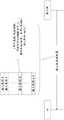
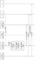
在接入种类控制中,基站广播包含有对于每个接入种类(AC)设定的控制数据(例如,限制率、以秒为单位的平均接入限制时间值)的信息,从而覆盖区域中的所有终端可以同时接收该信息并且执行接入控制,如图2中所示。通常,将接入种类控制应用为AC 0到9的目的是保护网络设备并且优化通信业务量,而将接入种类控制应用为AC 10和AC 11到15以使得不应用限制是用来实现紧急和高优先级通信的安全通信。基于图2中所示的控制流程的几种接入种类控制方法已经在LTE中指定了,并且在本文中进一步讨论。In access category control, the base station broadcasts information containing control data (for example, barring rate, average access barring time value in seconds) set for each access class (AC), so that All terminals of can simultaneously receive this information and perform access control, as shown in FIG. 2 . Generally, the purpose of applying access class control as
接入种类限制(ACB)是仅可应用于RRC空闲模式的接入控制机制。ACB在UE RRC层中执行。基于由网络广播的限制率信息,终端基于其AC确定是否允许发送连接请求。此外,存在可利用ACB来控制的两种类型的分组数据发送:对于通用分组呼叫(包括LTE语音(VoLTE))和紧急呼叫的连接请求的发送。定义了与用于普通数据信令(移动始发数据,例如MO数据)的限制参数分开的用于信令(例如,移动始发信令,例如MO信令)的限制参数。基于由网络广播的限制率信息,终端基于其AC确定是否允许发送连接请求。Access Class Barring (ACB) is an access control mechanism applicable only in RRC idle mode. ACB is performed in UE RRC layer. Based on the rate limiting information broadcast by the network, the terminal determines whether to allow sending a connection request based on its AC. Furthermore, there are two types of packet data transmissions that can be controlled with ACB: transmissions of connection requests for general packet calls (including Voice over LTE (VoLTE)) and emergency calls. Restriction parameters for signaling (eg mobile originated signaling such as MO signaling) are defined separately from restriction parameters for normal data signaling (mobile originated data such as MO data). Based on the rate limiting information broadcast by the network, the terminal determines whether to allow sending a connection request based on its AC.
特定于服务的接入控制(SSAC)是可应用于RRC空闲模式和RRC连接模式两者的接入种类控制方法。在该方法中,SSAC在NAS IMS层中执行。SSAC接入控制特征允许对多媒体电话(MMTEL服务,例如VoLTE和LTE视频(ViLTE)等)进行独立的接入控制。SSAC特征还应用于RRC连接模式,因为即使终端已经连接到网络,也可能需要对后台信令业务量(例如,对于UE中的IMS应用客户端与IMS服务器之间的后台同步业务量)进行接入控制。基于由网络广播的SSAC特定限制率信息,对于IMS语音、IMS视频或IMS SMS,终端根据其AC确定是否允许发送连接请求。Service Specific Access Control (SSAC) is an access class control method applicable to both RRC idle mode and RRC connected mode. In this method, SSAC is performed in the NAS IMS layer. The SSAC access control feature allows independent access control for multimedia telephony (MMTEL services such as VoLTE and Video over LTE (ViLTE), etc.). The SSAC feature is also applied in RRC connected mode, because background signaling traffic (e.g. for background synchronization traffic between an IMS application client in a UE and an IMS server) may need to be connected even if the terminal is already connected to the network. into control. Based on the SSAC specific limit rate information broadcasted by the network, for IMS voice, IMS video or IMS SMS, the terminal determines whether to allow sending a connection request according to its AC.
应当注意,为了优先化MMTEL服务,本文中讨论了如下机制,该机制对于与MMTEL服务呼叫类型相关联的连接请求跳过ACB特征。该构思是使正经受双重接入限制(例如,在常规ACB级别进行限制然后在SSAC级别进行限制)的MMTEL服务无效。It should be noted that in order to prioritize MMTEL services, a mechanism is discussed herein that bypasses the ACB feature for connection requests associated with MMTEL service call types. The idea is to disable MMTEL services that are subject to dual access restriction (eg restriction at regular ACB level and then at SSAC level).
对于不支持上述VoLTE功能的LTE终端,通过用于电路交换回退(CSFB)的接入控制来提供语音服务。定义了用于CSFB的ACB,以在终端仍驻留(camp)在LTE网络中时限制对于CSFB呼叫的连接请求。该接入控制机制应用于处于RRC空闲模式的UE。应当注意,为了在启用ACB时对CSFB呼叫进行优先化并且避免由于如本文中所述的ACB特征而导致CSFB呼叫被限制,已经在LTE中引入了特定于CSFB的接入限制控制。基于由网络广播的CSFB特定限制率信息,终端基于其AC确定是否允许发送连接请求。For LTE terminals that do not support the VoLTE function described above, voice services are provided through access control for Circuit Switched Fallback (CSFB). ACB for CSFB is defined to limit connection requests for CSFB calls while the terminal is still camped in the LTE network. This access control mechanism applies to UEs in RRC idle mode. It should be noted that in order to prioritize CSFB calls when ACB is enabled and avoid CSFB calls being barred due to ACB features as described herein, a CSFB-specific access barring control has been introduced in LTE. Based on the CSFB specific rate limiting information broadcasted by the network, the terminal determines whether to allow sending a connection request based on its AC.
特定于应用的数据通信拥塞控制(ACDC)是用于操作员的接入控制机制,以允许/防止来自处于空闲模式的UE中的特定的由运营商识别的应用的新接入尝试。该机制仅适用于处于RRC空闲模式的UE。归属网络可以利用至少四个和最多十六个ACDC类别来配置UE,特定的由运营商识别的应用与每个ACDC类别相关联。当配置时,在ACDC类别的基础上配置接入控制限制配置,当不存在时,则对于该ACDC类别,对小区的接入被认为不被限制。基于由网络广播的ACDC类别特定限制率信息,终端基于其AC来确定是否允许发送连接请求。Application Specific Data Communication Congestion Control (ACDC) is an access control mechanism for operators to allow/prevent new access attempts from specific operator-identified applications in UEs in idle mode. This mechanism only applies to UEs in RRC idle mode. The home network can configure the UE with at least four and up to sixteen ACDC classes, with specific operator-identified applications associated with each ACDC class. When configured, the access control restriction configuration is configured on the basis of the ACDC category, and when it does not exist, then for the ACDC category, the access to the cell is considered not to be restricted. Based on the ACDC class-specific rate information broadcast by the network, the terminal determines whether to allow sending a connection request based on its AC.
扩展接入种类限制(EAB)是可能仅可应用于处于RRC空闲模式的UE的一种接入限制控制方法。扩展接入限制(EAB)是如下机制,该机制供运营商控制来自被配置为EAB的UE(通常是机器类型通信(MTC)设备)的移动始发接入尝试,以便防止接入网和/或核心网的过载。在拥塞情况下,运营商可以约束来自被配置为EAB的UE的接入,同时允许来自其他UE的接入。被配置为EAB的UE被认为比其他UE更能容忍接入约束。当运营商确定适合于应用EAB时,网络广播需要的信息以对于特定区域中的UE提供EAB控制。网络广播位图,该位图包括对其应用扩展接入限制的AC(可能为0至9)以及对其应用EAB的UE的类别(类别a、b或c)。被配置为低接入优先级和扩展接入限制的UE还可以被配置为许可对低接入和扩展接入限制优先级约束的覆盖。该配置主要供如下应用或用户使用,该应用或用户在与其他UE竞争接入网络资源时,大部分时间都可以容忍由于低接入优先级而被推迟,但是有时,该应用或用户在低接入优先级配置将会阻止获得接入时也需要接入网络。为了在低优先级接入或扩展接入限制约束条件期间也获得网络接入,用户或应用(UE中的上层)可以请求UE在没有低接入优先级的情况下启动PDN连接的激活。Extended Access Class Barring (EAB) is one access barring control method that may be applicable only to UEs in RRC idle mode. Extended Access Barring (EAB) is a mechanism for operators to control mobile-originated access attempts from UEs (typically Machine Type Communication (MTC) devices) configured for EAB in order to prevent access network and/or or overloading of the core network. In congestion situations, the operator can restrict access from UEs configured as EAB, while allowing access from other UEs. UEs configured as EAB are considered to be more tolerant of access restrictions than other UEs. When the operator determines that it is suitable to apply EAB, the network broadcasts necessary information to provide EAB control for UEs in a specific area. The network broadcasts a bitmap that includes the AC (possibly 0 to 9) to which the extended access restriction applies and the category of the UE (category a, b or c) to which the EAB applies. UEs configured with low access priority and extended access restriction may also be configured to grant overrides to low access and extended access restriction priority constraints. This configuration is mainly used by applications or users who can tolerate being delayed due to low access priority most of the time when competing with other UEs for access to network resources, but sometimes The access priority configuration will prevent access from being required to be connected to the network. To gain network access also during low priority access or extended access restriction constraints, the user or application (upper layers in the UE) may request the UE to initiate activation of a PDN connection without low access priority.
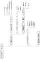
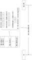
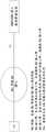
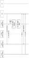
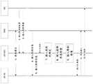
3GPP的RAN2工作组正在考虑统一的接入控制框架(例如,基于接入类别的无线电接入控制的一个共同框架),其中每个UE将使用默认或预配置的接入类别以基于由网络发信号通知的接入限制配置信息来评估是否允许接入网络(例如,在处于RRC空闲模式或RRC不活动模式时)或发送到网络(例如,在处于RRC连接模式时)。在图3中描绘了支持该统一方法的示例性接入控制流程(参见R2-1706505,NR的接入控制,3GPP TSG-RAN WG2 NR#2,爱立信)。该示例假设在UE AS中执行实际的接入控制(例如,图3中的步骤6)。3GPP's RAN2 working group is considering a unified access control framework (e.g., a common framework for access class-based radio access control), where each UE will use a default or pre-configured access class to Signaled access restriction configuration information to evaluate whether to allow access to the network (eg when in RRC idle mode or RRC inactive mode) or send to the network (eg when in RRC connected mode). An exemplary access control procedure supporting this unified approach is depicted in Figure 3 (see R2-1706505, Access Control for NR, 3GPP TSG-RAN
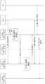
以下是对R2-1706505中捕获的信令流的简短描述:The following is a short description of the signaling flow captured in R2-1706505:
在步骤1,核心网在UE中配置接入类别。该配置包括与接入类别的事件类型、应用、服务或其他方面的组合有关的映射规则。如果需要,也可以在映射规则中使用SIM存储的接入种类(0-15)。这些映射规则是使用NAS信令从核心网配置的。这通常是专用信令,以便具有特定于UE的配置,并且通常在附接和例如注册区域更新期间执行。UE中的类别的配置结果可以示出为表格,包括配置规则和作为结果的类别两者。In
表1:UE中的接入类别配置示例Table 1: Example of access class configuration in UE
该示例示出了取决于接入种类、分片、应用和呼叫类型的接入类别,但是并不一定是需要考虑所有方面的情况。一旦接入与应用3有关,它可能例如始终会导致接入类别5,而与其他输入无关。所配置的接入类别存储在UE中。This example shows access classes depending on access class, fragment, application and call type, but not necessarily all aspects need to be considered. As soon as an access is related to
在步骤2,在UE中的NAS层中发生接入网络的触发。In
在步骤3中,NAS基于步骤1中的UE配置来确定该特定接入的接入类别。In
在步骤4,当请求建立连接时,NAS将所确定的接入类别提供给AS(RRC层)。In step 4, when requesting to establish a connection, the NAS provides the determined access category to the AS (RRC layer).
在步骤5,接收接入控制限制指示。RAN通过系统信息指示是否限制接入类别(例如,使用类似于ACDC的限制概率因子和限制时间、或类似于EAB的位图或其他方式)。该信令是RRC层的一部分。在R2-1706509(接入控制参数的信令,3GPP TSG-RAN WG2NR#2,爱立信)中进一步讨论了如何实现和传递这些参数,并且在图4中进一步示出。In step 5, an access control restriction indication is received. The RAN indicates whether to restrict the access category through system information (for example, using a restriction probability factor and a restriction time similar to ACDC, or a bitmap similar to EAB or other methods). This signaling is part of the RRC layer. How these parameters are implemented and delivered is further discussed in R2-1706509 (Signaling of Access Control Parameters, 3GPP TSG-
在步骤6,发生接入限制检查。在进行接入尝试(随机接入)之前,UE中的AS层使用所确定的接入类别以及所广播的系统信息来检查特定接入类别是否被限制。这通常是RRC层的一部分。In step 6, an access restriction check occurs. Before making an access attempt (random access), the AS layer in the UE checks whether a specific access class is barred using the determined access class and the broadcasted system information. This is usually part of the RRC layer.
在步骤7,如果UE中的AS层确定该特定接入不被限制,则它执行接入尝试。In
表2总结了用于接入控制的不同功能的分配。Table 2 summarizes the allocation of the different functions used for access control.
表2:接入控制功能的分配Table 2: Allocation of access control functions

鉴于5G NR要求以及5G系统预期支持的多种和各种服务和垂直行业,在确保可用网络容量以如下方式分配的同时,5G网络中的有效的接入控制是稳定的5G网络运行所需要的:该方式与运营商从提供的服务中获取最大利润的目标相一致,同时提供卓越的客户体验,并且符合对关键通信和紧急呼叫进行优先化的法规要求。Given the 5G NR requirements and the multiple and varied services and vertical industries that 5G systems are expected to support, effective access control in 5G networks is required for stable 5G network operation while ensuring that available network capacity is allocated in the following manner : This approach is consistent with the operator's goal of maximizing profit from the services provided, while providing a superior customer experience and complying with regulatory requirements to prioritize critical communications and emergency calls.
如本文中所论述的,3GPP的RAN2工作组正在考虑统一的接入控制框架(例如,基于接入类别的无线电接入控制的一个共同框架),其中每个UE将使用默认或预配置的接入类别以基于由网络发信号通知的接入限制配置信息来评估是否允许接入网络(例如,在处于RRC空闲模式或RRC不活动模式时)或发送到网络(例如,在处于RRC连接模式时)。As discussed herein, 3GPP's RAN2 working group is considering a unified access control framework (e.g., a common framework for access class-based radio access control), where each UE will use default or pre-configured access Entry category to evaluate whether to allow access to the network (e.g. when in RRC idle mode or RRC inactive mode) or send to the network (e.g. when in RRC connected mode) based on access restriction configuration information signaled by the network ).
需要解决的一个问题是用于AC限制配置的有效信令过程的设计。考虑到5G系统预期支持的大量服务和垂直行业集合以及对5G设计的前瞻性要求,可以考虑对于属性(例如事件类型、应用、服务、分片、呼叫类型、设备类别、QoS分类索引(QCI)、QoS流或用于定义接入类别的其他方面)的组合的许多接入类别映射规则,从而导致潜在的大量接入类别。如果设计不当,这些类别的信令及其对应的无线电接入限制配置参数可能代表大量开销。One issue that needs to be addressed is the design of an efficient signaling procedure for AC restriction configuration. Considering the large set of services and vertical industries expected to be supported by 5G systems and the forward-looking requirements for 5G design, it can be considered for attributes (such as event type, application, service, fragmentation, call type, device class, QoS Classification Index (QCI) , QoS flows, or other aspects used to define access classes), resulting in a potentially large number of access classes. These classes of signaling and their corresponding radio access restriction configuration parameters can represent significant overhead if not designed properly.
此外,由网络将UE配置为在其自身上具有接入类别可能代表信令开销挑战,因此,需要仔细地考虑用于为UE配置接入类别的信令的设计。例如,在UE中执行接入类别的配置可能要求来自核心网的信令。然后,当UE进行后续接入尝试时,可以使用该配置。这通常意味着在处于空闲和不活动的移动性期间,UE应该能够使用先前从核心网获得的配置。为了避免触发附加信令,尝试维护用于接入类别映射的规则并且不经常更改它们似乎是合理的。然而,用于由UE确定所存储的接入类别的配置的有效性的方法是应当解决的问题。Furthermore, configuring a UE by the network to have an access class on itself may represent a signaling overhead challenge, therefore, the design of the signaling used to configure the access class for the UE needs to be carefully considered. For example, performing configuration of the access class in the UE may require signaling from the core network. This configuration can then be used when the UE makes subsequent access attempts. This generally means that during idle and inactive mobility, the UE should be able to use the configuration previously obtained from the core network. To avoid triggering additional signaling, it seems reasonable to try to maintain the rules for access class mapping and change them infrequently. However, a method for the UE to determine the validity of the stored configuration of the access class is a problem that should be solved.
要解决的另一个问题是对于处于RRC连接模式的UE的接入限制控制的问题。需要设计对于处于RRC连接状态的UE在控制平面和用户平面中的接入控制的解决方案。例如,假设在用户平面中存在接入控制,并且在属于现有PDU会话的QoS流上有上行链路数据要发送。这样的上行链路发送可以经受接入控制。如果由于接入控制决定而不可以进行上行链路发送,则可能需要针对以下各项指定UE行为:Another problem to be solved is that of access barring control for UEs in RRC connected mode. A solution for access control in control plane and user plane for UE in RRC connected state needs to be designed. For example, assume there is access control in the user plane and there is uplink data to send on a QoS flow belonging to an existing PDU session. Such uplink transmissions may be subject to access control. If uplink transmission is not possible due to an access control decision, UE behavior may need to be specified for:
在通过接入控制而存在上行链路发送约束的情况下的缓冲器状态报告;Buffer status reporting in the presence of uplink transmission constraints through access control;
在通过接入控制而存在上行链路发送约束的情况下的调度请求处理;Scheduling request handling in the presence of uplink transmission constraints through access control;
在通过接入控制而存在上行链路发送约束的情况下的逻辑信道优先化;和/或Logical channel prioritization in the presence of uplink transmission constraints through access control; and/or
如果接入控制是由AS实现的,则UE NAS与UE AS之间的流控制。Flow control between UE NAS and UE AS if access control is implemented by AS.
另外,可能还需要解决在空闲模式和不活动模式下的接入控制。Additionally, access control in idle mode and inactive mode may also need to be addressed.
公开了用于接入类别配置信令的方法和系统。Methods and systems for access class configuration signaling are disclosed.
可以为UE配置两种类型的接入类别。一种类型的接入类别可以是规范中定义的接入类别。这些接入类别可以包括供PLMN工作人员、紧急服务、公用事业(例如水/天然气供应商)、安全服务等使用的特殊接入类别。可能在标准中指定的包括特殊接入类别的这些类型的接入类别可以在本文中被称为默认接入类别。可以为UE配置的其他类型的接入类别可以是未在标准中指定的接入类别。诸如接入类别的定义可以留给特定于实施和部署的场景,从而为运营商提供灵活性以供应服务差异化产品。例如,5G规范可以定义一系列接入类别和潜在的接入类别标识符。可以指定一部分接入类别标识符、对应的接入类别以及它们的使用和属性的详细信息,而可以将构成所指定的接入类别系列的其他部分的第二接入类别集在其含义和如何使用方面留给特定于实施或部署的场景。该第二类型的接入类别在本文中可以被称为“运营商定义的接入类别”。Two types of access categories can be configured for a UE. One type of access class may be an access class defined in a specification. These access categories may include special access categories for use by PLMN personnel, emergency services, utilities (eg water/gas suppliers), security services, and the like. These types of access classes, including special access classes, which may be specified in standards, may be referred to herein as default access classes. Other types of access classes that may be configured for the UE may be those not specified in the standard. Definitions such as access classes can be left to implementation- and deployment-specific scenarios, providing operators with the flexibility to offer service-differentiating offerings. For example, 5G specifications may define a series of access classes and potential access class identifiers. A subset of access class identifiers, corresponding access classes and details of their use and attributes may be specified, whereas a second set of access classes forming the rest of the specified family of access classes may be specified in terms of their meaning and how Usage aspects are left to implementation or deployment specific scenarios. This second type of access category may be referred to herein as an "operator-defined access category".
可以基于以下属性或分量中的一个或多个来定义接入类别:接入种类、分片、应用、OS、呼叫类型、业务流或分组流、服务数据流、QoS流、QCI,订阅简档(例如白金用户、黄金用户、白银用户和青铜用户)。Access classes can be defined based on one or more of the following attributes or components: access category, slice, application, OS, call type, traffic or packet flow, service data flow, QoS flow, QCI, subscription profile (e.g. Platinum, Gold, Silver and Bronze).
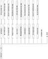
在图5中示出使用开放移动联盟设备管理(OMA DM)协议的接入类别配置的可能管理对象。在图6至图14中描绘接入类别管理对象的节点的配置。Possible managed objects configured using an access class of the Open Mobile Alliance Device Management (OMA DM) protocol are shown in FIG. 5 . Configurations of nodes accessing category management objects are depicted in FIGS. 6 to 14 .
如图6中所示的接入类别配置的另一方面涉及UE中存储的接入类别配置的有效性。接入类别配置信息可以包括有效性标准配置信息。下列标准中的一个或多个可用来定义和配置用于一个或多个接入类别的有效性规则:有效性区域、一天中的时间、与无线电信号质量、无线电信号强度阈值标准有关的无线电接入网络条件。在图14中描绘UE可以用来评估所存储的接入类别配置的有效性的有效性标准的可能的管理对象。Another aspect of the access class configuration as shown in Figure 6 relates to the validity of the access class configuration stored in the UE. The access category configuration information may include validity standard configuration information. One or more of the following criteria can be used to define and configure availability rules for one or more access classes: availability zone, time of day, radio access related to radio signal quality, radio signal strength threshold criteria access network conditions. Possible management objects of the validity criteria that the UE may use to assess the validity of the stored access class configurations are depicted in FIG. 14 .
在UE将接入类别信息发送到执行接入限制检查的UE实体之前,UE可以验证接入类别仍然有效(例如,接入类别满足有效性标准)。例如,如果接入限制检查由UE接入层(AS)来执行并且为UE非接入层(NAS)或该层内的实体配置接入类别信息,则UE NAS可以在将接入类别信息提供给AS以进行如本文中所述的接入限制检查之前验证接入类别有效性。当接入类别不再有效时,UE可以不在接入限制检查中使用该接入类别。Before the UE sends the access class information to the UE entity performing the access restriction check, the UE may verify that the access class is still valid (eg, the access class satisfies validity criteria). For example, if the access restriction check is performed by the UE Access Stratum (AS) and access category information is configured for the UE Non-Access Stratum (NAS) or an entity within this layer, the UE NAS may provide the access category information To the AS to verify access class validity before performing access restriction checks as described herein. When an access class is no longer valid, the UE may not use the access class in access restriction checks.
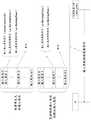
在一个示例中,公开了基于接入类别分量的接入类别配置。接入类别可以包含一个或多个接入类别分量。如图15中所示,接入类别分量可以是以下各项中的一个或多个:接入种类、分片、应用、OS、呼叫类型、业务流或分组流、服务数据流、QoS流、QCI、订阅简档(例如,白金用户、黄金用户、白银用户和青铜用户)。对于默认接入类别,接入类别分量的详细信息可以在标准中指定,如本文中所述。可以由核心网为UE配置一个或多个接入类别,其中每个接入类别包含一个或多个接入类别分量。在另一示例中,可以由无线电接入网(例如,gNB)为UE配置一个或多个接入类别,其中每个接入类别包含一个或多个接入类别分量。In one example, access category configuration based on access category components is disclosed. An access class may contain one or more access class components. As shown in Figure 15, the access category component may be one or more of the following: access category, slice, application, OS, call type, traffic or packet flow, service data flow, QoS flow, QCI, Subscription Profile (eg, Platinum User, Gold User, Silver User, and Bronze User). For the default access class, details of the access class components may be specified in the standard, as described herein. One or more access categories may be configured for the UE by the core network, where each access category includes one or more access category components. In another example, the UE may be configured with one or more access categories by the radio access network (eg, gNB), where each access category contains one or more access category components.
在示例中,每个接入类别分量可以由位图表示,其中,位图的给定值对应于接入类别分量的一个实例。对于每个接入分量,如图16中所示,可以首先为UE配置与可能最终由核心网为UE配置的潜在接入类别相对应的接入属性或分量的可能值或实例的列表。In an example, each access category component may be represented by a bitmap, where a given value of the bitmap corresponds to an instance of the access category component. For each access component, as shown in FIG. 16 , the UE may first be configured with a list of possible values or instances of access attributes or components corresponding to potential access categories that may eventually be configured for the UE by the core network.
为了给UE配置特定接入类别的目的,位图可以随后用来表示接入类别内的接入分量。例如,接入类别分量可以对应于预期通过通信网络运行的应用。可以最初为UE配置可以被用作网络中的接入类别配置的一部分的应用列表。为了支持具有特定接入类别的UE配置,UE可以使用位图来引用UE上已经配置的应用,然后可以使用该位图来配置应用ID,该应用ID是正在为UE配置的接入类别的分量。每个接入类别分量的位图可以具有不同的大小。在示例中,为了给UE配置接入类别,核心网向UE发信号通知与构成该接入类别的接入类别分量相对应的位图,如图17和图18中所示。在另一个示例中,为了给UE配置接入类别,无线电接入网(例如,gNB)向UE发信号通知与构成该接入类别的接入类别分量相对应的位图。The bitmap may then be used to represent the access components within the access class for the purpose of configuring the UE for a particular access class. For example, an access category component may correspond to an application intended to be run over a communication network. The UE may initially be configured with a list of applications that may be used as part of the access class configuration in the network. To support UE configuration with a specific access class, the UE can use a bitmap to reference already configured applications on the UE, which can then be used to configure the application ID, which is a component of the access class being configured for the UE . The bitmaps for each access category component may have different sizes. In an example, to configure an access class for a UE, the core network signals to the UE a bitmap corresponding to the access class components making up the access class, as shown in FIGS. 17 and 18 . In another example, to configure an access class for a UE, the radio access network (eg gNB) signals to the UE a bitmap corresponding to the access class components making up the access class.
在示例中,每个接入类别分量可以由枚举结构来表示,其中该枚举的每个值对应于接入类别分量的可能实例。例如,作为说明,以网络分片作为接入类别分量为例,运营商可以配置以下分片:eMBB分片_1,eMBB分片_2,eMBB分片_3,URLLC分片_1,URLLC分片_2,mMTC分片_1,mMTC分片_2和mMTC分片_3。网络分片的接入类别分量可以由以下枚举来表示:枚举{分片_1,eMBB分片_2,eMBB分片_3,URLLC分片_1,URLLC分片_2,mMTC分片_1,mMTC分片_2和mMTC分片_3}。为了给UE配置接入类别,核心网向UE发信号通知构成接入类别的接入类别分量的枚举值(例如,用于接入类别分量的URLLC分片_2对应于网络分片属性)。在另一示例中,为了给UE配置接入类别,无线电接入网(例如,gNB)向UE发信号通知构成接入类别的接入类别分量的枚举值(例如,用于接入类别分量的URLLC分片_2对应于网络分片属性)。In an example, each access category component may be represented by an enumeration structure, where each value of the enumeration corresponds to a possible instance of the access category component. For example, as an illustration, taking the network slice as the access category component as an example, the operator can configure the following slices: eMBB slice_1, eMBB slice_2, eMBB slice_3, URLLC slice_1, URLLC Shard_2, mMTC Shard_1, mMTC Shard_2 and mMTC Shard_3. The access category component of a network segment can be represented by the following enumeration: enum {segment_1, eMBB segment_2, eMBB segment_3, URLLC segment_1, URLLC segment_2, mMTC segment slice_1, mMTC slice_2 and mMTC slice_3}. To configure the access class for the UE, the core network signals to the UE the enumerated values of the access class components that make up the access class (e.g. URLLC slice_2 for the access class component corresponds to the network slice attribute) . In another example, to configure an access class for a UE, the radio access network (e.g. gNB) signals to the UE the enumerated values of the access class components that make up the access class (e.g. The URLLC fragmentation_2 corresponds to the network fragmentation attribute).
使用图15中描绘的示例接入类别,接入分量的枚举示例可以被枚举如下:Using the example access classes depicted in Figure 15, enumerated examples of access components may be enumerated as follows:
呼叫类型:枚举{“始发信令”,“紧急呼叫”,“始发语音”,“始发视频”,“始发SMSoIP”,“始发SMS”,“终止呼叫”,“始发呼叫”,“移动始发CS回退”}CallType: enum {"Originating Signaling", "Emergency Call", "Originating Voice", "Originating Video", "Originating SMSoIP", "Originating SMS", "Terminating Call", "Originating call", "Mobile Originated CS Fallback"}
网络分片:枚举{eMBB分片_1,eMBB分片_2,eMBB分片_3,URLLC分片_1,URLLC分片_2,mMTC分片_1,mMTC分片_2和mMTC分片_3)Network Sharding: enum {eMBB Shard_1, eMBB Shard_2, eMBB Shard_3, URLLC Shard_1, URLLC Shard_2, mMTC Shard_1, mMTC Shard_2 and mMTC Fragment_3)
操作系统(OS):枚举{苹果iOS,安卓,黑莓,视窗,塞班,BADA,Palm OS(掌上OS),Open WebOS(开放网络OS),Maemo,MeeGo,Verdict}Operating system (OS): enumeration {Apple iOS, Android, Blackberry, Windows, Symbian, BADA, Palm OS (handheld OS), Open WebOS (open network OS), Maemo, MeeGo, Verdict}
应用:{电影和视频应用,例如Netflix,Hulu,YouTube,YouTube TV,Spotify等;新闻应用,例如NYTimes(纽约时报),Vice News(副新闻),The WashingtonPost(华盛顿邮报),CBS Sports(CBS体育)等;社交媒体应用,例如Facebook,Instagram,Twitter等;即时通信应用,例如Skype,Messenger,WhatsApp,Snapchat等;游戏应用,例如Steam,PlayStation应用,XboxOne,V2V应用,运营商特定应用等}Apps: {Movie and Video Apps such as Netflix, Hulu, YouTube, YouTube TV, Spotify, etc.; News Apps such as NYTimes (New York Times), Vice News (Vice News), The WashingtonPost (Washington Post), CBS Sports (CBS Sports), etc.; social media applications, such as Facebook, Instagram, Twitter, etc.; instant messaging applications, such as Skype, Messenger, WhatsApp, Snapchat, etc.; game applications, such as Steam, PlayStation applications, XboxOne, V2V applications, operator-specific applications, etc.}
接入种类:{AC0,AC1,AC2,AC3,AC4,AC5,AC6,AC7,AC8,AC9}Access type: {AC0, AC1, AC2, AC3, AC4, AC5, AC6, AC7, AC8, AC9}
特殊接入种类:{AC11,AC12,AC13,AC14,AC15)Special access types: {AC11, AC12, AC13, AC14, AC15)
图19是接入类别配置信令的示例,其中每个接入类别被表示为元组,并且其中元组的每个元素是构成该接入类别的分量的枚举值。Fig. 19 is an example of access class configuration signaling, where each access class is represented as a tuple, and where each element of the tuple is an enumerated value of components constituting the access class.
在示例中,一些接入类别分量可以由位图来表示,而其他一些接入类别分量可以由枚举结构来表示。为了给UE配置接入类别,核心网向UE发信号通知一些接入类别分量作为位图,而使用枚举结构向UE发信号通知其他一些接入类别。In an example, some access category components may be represented by bitmaps, while others may be represented by enumerated structures. To configure an access class for a UE, the core network signals to the UE some access class components as bitmaps and some other access classes using an enumerated structure.
在示例中,为了给UE配置接入类别,无线电接入网(例如,gNB)向UE发信号通知一些接入类别分量作为位图,而使用枚举结构向UE发信号通知其他一些接入类别。In an example, to configure an access class for a UE, the radio access network (e.g. gNB) signals to the UE some access class components as a bitmap and some other access classes using an enumerated structure .
核心网可以通过专用NAS控制平面信令为UE配置接入类别。在示例中,核心网使用NAS控制平面信令为UE配置接入类别。核心网可以在移动性管理过程期间为UE配置接入类别信息。使用LTE术语,可以由核心网用来在UE处配置接入类别的移动性管理过程的示例可以是例如跟踪区域更新过程、UE附接或组合附接过程、分离和组合分离过程、服务请求过程、NAS消息的传输或NAS消息的通用传输。可以通过接入类别管理功能(ACMF)来实现接入类别配置的控制平面NAS信令。这样的功能本身可能是其他核心网功能的一部分,例如现在正被指定为5G核心网架构的一部分的接入和移动性管理功能(AMF)。The core network can configure the access category for the UE through dedicated NAS control plane signaling. In an example, the core network configures the access category for the UE using NAS control plane signaling. The core network may configure access category information for the UE during the mobility management procedure. Using LTE terminology, examples of mobility management procedures that can be used by the core network to configure the access class at the UE can be e.g. tracking area update procedure, UE attach or combined attach procedure, detach and combined detach procedure, service request procedure , transmission of NAS messages or general transmission of NAS messages. Control plane NAS signaling for access class configuration may be implemented through an Access Class Management Function (ACMF). Such functions may themselves be part of other core network functions, such as the Access and Mobility Management Function (AMF), which is now being specified as part of the 5G core network architecture.
在示例中,如图20和图21中所示,核心网可以通过专用NAS用户平面信令为UE配置接入类别。在这种情况下,ACMF可能位于用户平面中。如图20和图21中所示,Nx可以是UE与用户平面中的接入类别管理实体之间的参考点,以经由拉取机制(UE发起的会话)或推送机制(ACMF发起的会话)进行直接查询。这可以使得能够向UE半静态或动态(相对于静态)地提供接入类别信息,以支持与3GPP接入和非3GPP接入有关的接入限制控制过程。通过Nx进行的通信可以是安全的通信。Nx接口可以在IP级别以上实现。在示例中,ACMF可以是核心网的新网络功能。在另一个示例中,ACMF可以是已经定义的5G核心网功能(例如AMF(接入和移动性管理)功能或PCF(策略控制功能))的一部分。ACMF也可以是作为被指定为演进分组核心(EPC)网络架构的一部分的接入网发现和选择功能(ANDSF)元素的一部分的功能,或者是5G核心网中的等效功能。In an example, as shown in FIG. 20 and FIG. 21 , the core network may configure the access category for the UE through dedicated NAS user plane signaling. In this case, ACMF may be located in the user plane. As shown in Figure 20 and Figure 21, Nx can be a reference point between the UE and the Access Category Management Entity in the user plane to communicate via a pull mechanism (UE-initiated session) or a push mechanism (ACMF-initiated session) Make a direct inquiry. This may enable semi-static or dynamic (vs. static) provision of access category information to UEs to support access restriction control procedures related to 3GPP access and non-3GPP access. Communications via Nx may be secure communications. The Nx interface can be implemented above the IP level. In an example, ACMF may be a new network function of the core network. In another example, ACMF may be part of already defined 5G core network functions such as AMF (Access and Mobility Management) function or PCF (Policy Control Function). ACMF may also be a function as part of the Access Network Discovery and Selection Function (ANDSF) element specified as part of the Evolved Packet Core (EPC) network architecture, or an equivalent function in the 5G core network.
在示例中,无线电接入网(例如,gNB)通过专用RRC信令为UE配置接入类别。使用LTE RRC过程作为参考,无线电接入网可以使用以下RRC消息中的一个或多个向UE发信号通知接入类别配置信息:RRC连接释放(RRCConnectionRelease)消息,RRC连接重新配置(RRCConnectionReconfiguration)消息。例如,在NR中,具有旨在向UE发信号通知RRC连接释放的RRC连接释放代码点的新RRC连接重新配置消息可以用来为UE配置接入类别配置信息。可以向UE预先提供USIM中存储的接入类别。In an example, the radio access network (eg gNB) configures the access category for the UE through dedicated RRC signaling. Using LTE RRC procedures as a reference, the radio access network may signal the access class configuration information to the UE using one or more of the following RRC messages: RRCConnectionRelease message, RRCConnectionReconfiguration message. For example, in NR, a new RRC connection reconfiguration message with an RRC connection release code point intended to signal RRC connection release to the UE can be used to configure the UE with access class configuration information. The access category stored in the USIM may be pre-provided to the UE.
在基于接入类别分量的接入类别设计的示例中,接入类别可以包括的接入类别分量的数量被预先定义或指定。可能的是,该数量可以是固定的。在接入类别分量到接入类别的布置内的接入类别分量的顺序可以被预先定义。例如,假设接入类别分量由位图来表示,并且接入类别中的接入类别分量的总数量被指定或预先定义为十,则接入类别可以是包括例如十个接入类别分量位图的较大位图,其中每个接入类别分量位图在接入类别位图中的位置被预先定义(例如,被指定)。例如,接入类别可以按顺序包括接入种类、分片、应用、OS、呼叫类型、业务流或分组流、服务数据流、QoS流、QCI、订阅简档分量,并且他们在接入类别中的对应位图可以按该顺序出现,其中接入类别位图的最高有效位将与接入种类相对应,而接入类别位图的最低有效位可以与订阅简档相对应。该概念在图22中示出,其中,接入类别X的最高有效位是接入分量1的位b_0,而接入类别X的最低有效位是接入分量n的位b_kn。在该图中,接入类别分量“接入分量1”具有b_k1+1个位,接入分量1具有b_ki+1个位,而接入分量n具有b_kn+1个位。In an example of an access class design based on access class components, the number of access class components that an access class may include is predefined or specified. Possibly, this number could be fixed. The order of the access class components within the access class component to access class arrangement may be predefined. For example, assuming that the access class components are represented by a bitmap, and the total number of access class components in the access class is specified or predefined as ten, the access class may be a bitmap comprising, for example, ten access class components A larger bitmap of , wherein the position of each access category component bitmap in the access category bitmap is predefined (eg, specified). For example, an access class may include access class, slice, application, OS, call type, traffic or packet flow, service data flow, QoS flow, QCI, subscription profile components in order, and they are in the access class The corresponding bitmaps for can appear in that order, where the most significant bits of the access class bitmap will correspond to the access class, and the least significant bits of the access class bitmap can correspond to the subscription profile. This concept is illustrated in Figure 22, where the most significant bit of access class X is bit b_0 of
类似地,假设接入类别分量由枚举结构来表示,并且接入类别中的接入类别分量的总数量被指定或预先定义为十,则接入类别可以被表示为由枚举结构表示的接入类别分量的10个元组,例如({接入种类枚举},{分片枚举},{应用枚举},{OS枚举},{呼叫类型枚举},{业务流或分组流枚举},{服务数据流枚举},{QoS流枚举},{QCI枚举})。Similarly, assuming that the access category components are represented by an enumeration structure, and the total number of access category components in an access category is specified or predefined as ten, the access category may be represented as represented by an enumeration structure A 10-tuple of access class components, for example ({Access class enumeration}, {Fragment enumeration}, {Application enumeration}, {OS enumeration}, {Call type enumeration}, {Business flow or Packet Flow Enumeration}, {Service Data Flow Enumeration}, {QoS Flow Enumeration}, {QCI Enumeration}).
在一个示例中,公开了不基于接入类别分量的接入类别配置信令。接入类别信令可以不假设使用接入类别分量作为接入类别的组成部分。相反,接入类别的属性(例如,接入种类、分片、应用、OS、呼叫类型、业务流或分组流、服务数据流、QoS流、QCI、订阅简档等)的所有可能组合可以被枚举,并且被分配接入类别值或接入类别标识符。接入类别属性组合和接入类别值之间的映射可以被预先定义或指定。如本文中所述,可以在标准中指定接入类别属性的可能组合的子集以及相关联的接入类别值,而接入类别属性和相关联的接入类别值的可能组合的剩余集合留给由网络运营商进行特定于部署的配置。换句话说,接入类别属性的可能组合可以划分为两个子组,其中一个组在标准中被指定为具有相关联的默认接入类别值的默认组合,而接入类别属性和相关联的接入类别值的组合的第二组的配置留给由网络运营商进行的特定于部署的配置。这些第二组在本文中可以被称为运营商定义的接入类别。运营商定义的接入类别可以由位图或由枚举结构来表示。在一个示例中,核心网可以使用NAS专用控制平面信令向UE发信号通知接入类别配置信息(默认接入类别和/或运营商定义的接入类别)。在另一示例中,核心网可以使用NAS专用用户平面信令向UE发信号通知接入类别配置信息(默认接入类别和/或运营商定义的接入类别)。在另一示例中,无线电接入网(例如,gNB)可以使用RRC信令为UE配置接入类别配置信息。应当注意,对于运营商定义的接入类别,可能需要为UE配置接入类别的属性的详细信息。随后,网络可以可选地以位图的形式、或以枚举值或接入类别标识符的形式为UE配置允许UE使用的接入类别。对于默认接入类别,假定在标准中指定了这些接入类别的属性或分量的详细信息。结果,可以仅以位图或枚举值或接入类别标识符的形式为UE配置允许UE使用的默认接入类别。In one example, access class configuration signaling that is not based on access class components is disclosed. Access class signaling may not assume the use of access class components as components of the access class. Instead, all possible combinations of attributes of an access class (e.g., access class, slice, application, OS, call type, traffic or packet flow, service data flow, QoS flow, QCI, subscription profile, etc.) enumeration and is assigned an access class value or an access class identifier. The mapping between access category attribute combinations and access category values may be pre-defined or specified. As described herein, a subset of possible combinations of access class attributes and associated access class values may be specified in the standard, while the remaining set of possible combinations of access class attributes and associated access class values remain Deployment-specific configuration to be performed by the network operator. In other words, the possible combinations of access class attributes can be divided into two subgroups, one of which is specified in the standard as the default combination with an associated default access class value, and the access class attribute and associated access class The configuration of the second set of combinations of input category values is left to deployment-specific configuration by the network operator. These second groups may be referred to herein as operator-defined access categories. Operator-defined access categories can be represented by bitmaps or by enumeration structures. In one example, the core network may use NAS-specific control plane signaling to signal the access class configuration information (default access class and/or operator-defined access class) to the UE. In another example, the core network may signal the access category configuration information (default access category and/or operator defined access category) to the UE using NAS dedicated user plane signaling. In another example, the radio access network (eg, gNB) may configure the UE with access category configuration information using RRC signaling. It should be noted that for the access category defined by the operator, it may be necessary to configure the detailed information of the attributes of the access category for the UE. Subsequently, the network may optionally configure the UE with the access category allowed to be used in the form of a bitmap, or in the form of an enumeration value or an access category identifier. For default access classes, it is assumed that details of the attributes or components of these access classes are specified in the standard. As a result, the default access classes the UE is allowed to use can be configured for the UE only in the form of bitmaps or enumerated values or access class identifiers.
附加到或替代接入类别,可以标识和/或发送用于接入尝试的接入标识符。如上所述,可以基于一个或多个属性(例如接入种类、分片、应用、OS、呼叫类型、业务流或分组流、服务数据流、QoS流、QCI、订阅简档(例如白金用户、黄金用户、白银用户和青铜用户))来定义接入类别。如图5中所示,接入类别配置可以包括这些属性中的一个或多个、AC值和订阅简档标识符(其可以等效地表示为接入标识符)。例如,用于接入尝试的接入标识符可以包括以下指示:UE被配置用于关键任务服务,例如供第一响应者使用;或者该设备被配置为监视患者的生物特征信息。应当理解,在本文中的任何示例中,其中将接入类别从一个实体发送到另一个实体,或者从一个实体内的一个协议层发送到另一个协议层,可以与接入类别一起发送接入标识符,或者可以代替接入类别来发送接入标识符。接入尝试的接入标识符可以附加地或替代地用来确定该接入尝试是否被限制。In addition to or instead of an access class, an access identifier for an access attempt may be identified and/or transmitted. As mentioned above, it can be based on one or more attributes (such as access category, slice, application, OS, call type, traffic or packet flow, service data flow, QoS flow, QCI, subscription profile (such as platinum user, Gold user, silver user and bronze user)) to define the access category. As shown in Figure 5, an access class configuration may include one or more of these attributes, an AC value, and a subscription profile identifier (which may equivalently be denoted as an access identifier). For example, an access identifier for an access attempt may include an indication that the UE is configured for mission-critical services, such as for use by first responders, or that the device is configured to monitor biometric information of a patient. It should be understood that in any example herein where an access class is sent from one entity to another, or from one protocol layer within an entity to another, the access class may be sent along with the access class identifier, or the access identifier may be sent instead of the access class. An access identifier of an access attempt may additionally or alternatively be used to determine whether the access attempt is barred.
公开了用于接入限制控制参数信令的方法和系统。UE可以基于由无线电接入网(RAN)(例如,gNB)广播的对应接入类别的接入限制率(或可互换的接入限制因子)和接入限制平均时间来执行接入限制检查,或者UE可以基于由RAN广播的对应接入的布尔接入参数执行接入限制检查,该布尔接入参数指示对于接入种类是允许接入还是限制接入。例如,在基于接入限制率和接入限制平均时间的接入限制检查的情况下,UE可以抽取(draw)均匀分布在0和1之间的随机数rand,例如0≤rand<1。如果'rand'小于由“AC限制参数”中包括的ac-BarringFactor(ac限制因子)指示的值(其中AC表示接入类别(而不是接入种类)),则UE认为对小区的接入不被限制;否则,UE认为小区在ac-BarringTime(ac限制时间)持续时间内被限制。如果不允许接入尝试,则随后可能会在如下时间段内限制相同类型的其他接入尝试,该时间段是根据向UE发信号通知的对于该接入类别的接入限制平均持续时间以及由该UE抽取的随机数rand来计算的。用于接入类别的接入限制因子可以在范围[0,1)内,并且可以采用例如以下值之一:p00=0,p05=0.05,p10=0.10,…,p95=0.95。Methods and systems for access restriction control parameter signaling are disclosed. The UE may perform an access barring check based on the access barring rate (or interchangeable access barring factor) and the access barring average time broadcasted by the radio access network (RAN) (e.g. gNB) for the corresponding access class , or the UE may perform an access restriction check based on a Boolean access parameter broadcast by the RAN for the corresponding access indicating whether access is allowed or restricted for the access class. For example, in the case of the access restriction check based on the access restriction rate and the average access restriction time, the UE may draw (draw) a random number rand uniformly distributed between 0 and 1, for example 0≦rand<1. If 'rand' is less than the value indicated by the ac-BarringFactor (ac barring factor) included in the "AC barring parameter" (where AC indicates the access class (not the access class)), the UE considers that the access to the cell is not is barred; otherwise, the UE considers the cell to be barred within the duration of ac-BarringTime (ac barring time). If an access attempt is not allowed, other access attempts of the same type may subsequently be barred for a time period based on the average duration of access barring for that access class signaled to the UE and determined by It is calculated by the random number rand drawn by the UE. The access restriction factor for the access class may be in the range [0,1) and may take eg one of the following values: p00=0, p05=0.05, p10=0.10, . . . , p95=0.95.
在基于布尔接入限制参数执行接入限制检查的情况下,如果布尔接入限制参数被设置为1,则UE可以认为对小区的接入被限制,否则,UE认为对小区的接入不被限制。In case the access restriction check is performed based on the Boolean access restriction parameter, if the Boolean access restriction parameter is set to 1, the UE may consider the access to the cell to be restricted, otherwise, the UE shall consider the access to the cell not to be restricted limit.
由RAN(例如,gNB)进行的接入限制参数的信令可以基于以下方案中的一个或多个:Signaling of access restriction parameters by the RAN (eg gNB) may be based on one or more of the following schemes:
发信号通知接入限制参数的部分列表,包括发信号通知接入类别索引;Signal a partial list of access restriction parameters, including a signaled access category index;
发信号通知接入限制参数的完整列表,其中以位图的形式发信号通知接入类别信息;和/或signaling a complete list of access restriction parameters, where the access category information is signaled in the form of a bitmap; and/or
发信号通知接入限制参数的部分列表和完整列表的组合。A combination of a partial list and a full list of access restriction parameters is signaled.
在这些方法中的任何一个中,无线电接入网(例如,gNB)可以通过RRC共同信令(例如,系统信息广播信令)或RRC专用信令为UE配置接入限制参数,以支持处于RRC连接模式下的接入控制。在图23-图28中示出接入限制控制参数的信令的示例。在这些图中的任何一个中,可以在每个PLMN的基础上向UE发信号通知接入限制控制参数(接入限制率、接入限制平均时间或布尔接入限制参数),即,例如在网络共享的情况下,单个接入限制控制参数信令消息可以在每个PLMN的基础上携带对于一个以上PLMN的接入限制参数。In any of these methods, the radio access network (eg, gNB) can configure access restriction parameters for the UE through RRC common signaling (eg, system information broadcast signaling) or RRC dedicated signaling to support Access control in connected mode. Examples of signaling of access restriction control parameters are shown in FIGS. 23-28 . In any of these figures, an access restriction control parameter (access restriction rate, access restriction average time or Boolean access restriction parameter) may be signaled to the UE on a per-PLMN basis, i.e., for example in In the case of network sharing, a single access restriction control parameter signaling message may carry access restriction parameters for more than one PLMN on a per-PLMN basis.
图23和图24提供了接入限制参数信令的示例,其中网络正在广播部分列表的限制参数,该部分列表包含网络中的可用接入类别N当中的m个接入类别(例如,m小于或等于N)。在该示例中,可以假设核心网已经为UE的总体种群配置了接入类别集,该接入类别集包含等于或大于m的数量的接入类别,但是其中潜在地为每个UE配置数量n个接入类别,其中n大于或等于1但小于N(例如,参见图18或图19)。对于核心网已经为UE配置的并且RAN(例如gNB)正在广播接入限制参数的每个接入类别,UE可以创建接入类别和对应的接入限制参数之间的关联。为了使UE执行这样的关联,无线电接入网(RAN)可以对于m个接入类别中的每个接入类别广播唯一接入类别标识符以及接入限制参数。Figures 23 and 24 provide examples of access restriction parameter signaling, where the network is broadcasting restriction parameters for a partial list containing m access categories out of available access categories N in the network (e.g., m less than or equal to N). In this example, it can be assumed that the core network has configured an access category set for the overall population of UEs, which contains a number of access categories equal to or greater than m, but where potentially a number n is configured for each UE Access categories, where n is greater than or equal to 1 but less than N (see, for example, Figure 18 or Figure 19). For each access category that the core network has configured for the UE and the RAN (eg gNB) is broadcasting access restriction parameters, the UE may create an association between the access category and the corresponding access restriction parameters. In order for the UE to perform such an association, the radio access network (RAN) may broadcast a unique access category identifier and access restriction parameters for each of the m access categories.
附加地或替代地,UE可以隐式地导出接入限制参数正被广播的每个接入类别的唯一接入类别标识符。例如,假设RAN(例如gNB)使用包含大小为N的数组(array)的数据结构,其中N表示可用于网络中的接入控制的接入类别的总体数量,包括默认接入类别、特殊接入类别或运营商定义的接入类别。UE可以隐式地导出接入限制参数正被RAN(例如,gNB)广播的m个接入类别中的每个接入类别的接入类别唯一标识符,作为与接入类别在大小为N的数组(例如位图)中的位置相对应的索引。例如,参考图25,UE可以隐式地将接入类别X的唯一标识符导出为X(例如,接入类别X的唯一标识符是接入类别在大小为N的数组中的位置,即,在该示例中是大小为N的数组(例如位图)中的第X个位置)。对于已经由核心网为UE配置的每个接入类别,如果对于接入类别的限制参数由网络广播,则UE在其内部数据库中存储对应的接入限制参数。UE可以使用所存储的和有效的接入限制参数来执行本文中公开的接入限制检查。Additionally or alternatively, the UE may implicitly derive a unique access class identifier for each access class for which the access restriction parameters are being broadcast. For example, assume that the RAN (e.g. gNB) uses a data structure containing an array of size N, where N represents the total number of access categories available for access control in the network, including default access categories, special access class or operator-defined access class. The UE may implicitly derive an access category unique identifier for each of the m access categories that the access restriction parameter is being broadcast by the RAN (e.g. gNB) as The index corresponding to the position in the array (such as a bitmap). For example, referring to Figure 25, the UE may implicitly derive the unique identifier of access category X as X (e.g., the unique identifier of access category X is the position of the access category in an array of size N, i.e., In the example is the Xth position in an array of size N (e.g. a bitmap). For each access category that has been configured for the UE by the core network, if the restriction parameters for the access category are broadcast by the network, the UE stores the corresponding access restriction parameters in its internal database. The UE may use the stored and valid access barring parameters to perform the access barring checks disclosed herein.
可以根据对应的系统信息块(SIB)有效性规则的有效性来处理接入限制参数的有效性。图23中示出的示例假设为UE配置接入限制率和平均接入限制时间,而图24中的示例假设对于一些接入类别的接入控制是基于接入限制率和接入限制平均时间的,而对于一些接入类别的接入控制是基于布尔接入控制的(例如,允许或不允许对小区的接入)。例如,对于默认接入类别或特殊接入类别(其中一些可能在标准中指定),可以指定基于通过布尔参数的接入控制的接入控制。The validity of the access restriction parameters may be handled according to the validity of the corresponding System Information Block (SIB) validity rules. The example shown in Figure 23 assumes that the access restriction rate and the average access restriction time are configured for the UE, while the example in Figure 24 assumes that the access control for some access classes is based on the access restriction rate and the access restriction average time , whereas for some access classes the access control is based on Boolean access control (eg, allowing or disallowing access to a cell). For example, for default access classes or special access classes (some of which may be specified in standards), access control based on access control via Boolean parameters may be specified.
图25和图26提供了接入限制参数信令的示例,其中网络正在广播对于网络中的可用接入类别N的完整列表的接入限制参数。对于核心网已经为UE配置的(如上所述)并且RAN(例如gNB)正在广播接入限制参数的n个接入类别中的每个接入类别,UE可以创建接入类别和对应的接入限制参数之间的关联。为了使UE执行这样的关联,UE可以隐式地导出接入限制参数正被广播的每个接入类别的唯一接入类别标识符。例如,假设RAN(例如gNB)使用包含大小为N的数组的数据结构,其中N表示可用于网络中的接入控制的接入类别的总体数量,包括默认接入类别、特殊接入类别或运营商定义的接入类别。Figures 25 and 26 provide an example of access restriction parameter signaling where the network is broadcasting access restriction parameters for the complete list of access categories N available in the network. For each of the n access categories that the core network has configured for the UE (as described above) and for which the RAN (e.g. gNB) is broadcasting access restriction parameters, the UE can create an access category and a corresponding access Restricts associations between parameters. In order for the UE to perform such an association, the UE may implicitly derive a unique access class identifier for each access class for which the access restriction parameters are being broadcast. For example, assume that the RAN (e.g. gNB) uses a data structure containing an array of size N, where N represents the total number of access classes available for access control in the network, including default access class, special access class or operating Provider-defined access categories.
UE可以隐式地导出接入限制参数正被RAN(例如,gNB)广播的每个接入类别的接入类别唯一标识符,作为与接入类别在大小为N的数组(例如位图)中的位置相对应的索引。例如,参考图25,UE可以隐式地将接入类别X的唯一标识符导出为X(例如,接入类别X的唯一标识符是接入类别在大小为N的数组或位图中的位置,即,在该示例中是在大小为N的数组或位图中的第X个位置)。图25中示出的示例假设为UE配置接入限制率和平均接入限制时间,而图26中的示例假设对于一些接入类别的接入控制是基于接入限制率和接入限制平均时间的,而对于一些接入类别的接入控制是基于布尔接入控制的(例如,允许或不允许对小区的接入)。例如,对于默认接入类别或特殊接入类别(其中一些可能在标准中指定),可以指定基于通过布尔参数的接入控制的接入控制。The UE may implicitly derive the Access Class Unique Identifier for each access class for which the access restriction parameters are being broadcast by the RAN (e.g. gNB) as an array of size N (e.g. a bitmap) with the access class The index corresponding to the position of . For example, referring to Figure 25, the UE may implicitly derive the unique identifier of access category X as X (e.g., the unique identifier of access category X is the position of the access category in an array or bitmap of size N , that is, in this example the Xth position in an array or bitmap of size N). The example shown in Figure 25 assumes that the access restriction rate and the average access restriction time are configured for the UE, while the example in Figure 26 assumes that the access control for some access classes is based on the access restriction rate and the access restriction average time , whereas for some access classes the access control is based on Boolean access control (eg, allowing or disallowing access to a cell). For example, for default access classes or special access classes (some of which may be specified in standards), access control based on access control via Boolean parameters may be specified.
对于已经由核心网为UE配置的每个接入类别,如果对于接入类别的限制参数由网络广播,则UE可以在其内部数据库中存储对应的接入限制参数。UE可以使用所存储的和有效的接入限制参数来执行如本文中所述的接入限制检查。可以根据对应的系统信息块(SIB)有效性规则的有效性来处理接入限制参数的有效性。For each access category that has been configured for the UE by the core network, if the restriction parameters for the access category are broadcast by the network, the UE may store the corresponding access restriction parameters in its internal database. The UE may use the stored and valid access restriction parameters to perform access restriction checks as described herein. The validity of the access restriction parameters may be handled according to the validity of the corresponding System Information Block (SIB) validity rules.
图27和图28示出了如下示例,其中,按照如本文中所述的部分信令列表的方案向UE发信号通知一些接入限制参数,而按照也如本文中所述的完整信令列表的方案向UE发信号通知一些接入限制参数。例如,接入类别可以包括默认接入类别(包括特殊接入类别)和运营商定义的接入类别。可以在标准中指定部分或全部默认接入类别及其用于接入控制(例如,基于接入限制率和接入限制平均时间的接入控制与基于布尔接入限制的接入控制),而运营商定义的接入类别及其用于接入控制可以留给运营商决定。例如,包括特殊接入类别的默认接入类别的总体数量可以是k。在这样的情况下,可以使用其中网络广播了对于可用接入类别的完整列表的接入限制参数的接入限制参数信令,不同之处在于,在该情况下,可用接入类别的完整列表可能限于在标准或包括所指定的特殊接入类别的默认接入类别中指定的列表,该列表在图25和图26中所示的示例的情况下包括k个接入类别。Figures 27 and 28 show examples in which some access restriction parameters are signaled to the UE according to the scheme of a partial signaling list as described herein, while according to the scheme of a complete signaling list as also described herein The scheme of [0004] signals some access restriction parameters to the UE. For example, the access categories may include default access categories (including special access categories) and operator-defined access categories. Some or all of the default access categories and their use for access control may be specified in the standard (e.g. access control based on access restriction rate and average time to access restriction vs. access control based on Boolean access restriction), whereas The operator-defined access categories and their use for access control can be left to the operator's decision. For example, the total number of default access classes including special access classes may be k. In such cases, access restriction parameter signaling may be used in which the network broadcasts the access restriction parameters for the complete list of available access classes, except that in this case the complete list of available access classes Possibly limited to a list specified in the standard or a default access class including specified special access classes, which list includes k access classes in the case of the example shown in Figs. 25 and 26 .
可以使用本文中描述的部分列表信令机制向UE发信号通知接入限制参数。在图27或图28中所示的示例中,接入限制参数正被发信号通知的接入类别的数量m可以小于或等于可用于网络中的接入控制的运营商定义的接入类别(Nc)的总体数量。The access restriction parameters may be signaled to the UE using the partial list signaling mechanism described herein. In the example shown in Figure 27 or Figure 28, the number m of access classes for which the access restriction parameter is being signaled may be less than or equal to the operator-defined access classes ( Nc) the overall number.
公开了用于对处于RRC_IDLE(RRC空闲)模式下的UE进行接入控制的方法和系统。图29和图30中所示以及下面进一步描述的过程可以用来响应于接入层(AS)之上的UE的上层内的事件对处于RRC_IDLE(RRC空闲)下的UE执行接入控制,从而要求UE向核心网发起NAS信令连接,以及因此要求UE在向网络发起信令连接之前执行接入控制。上层中的要求UE发起NAS信令连接的事件可以包括用户平面中的事件(例如,如果数据变得可用于发送)、或控制平面中的事件(例如跟踪区域的改变),从而要求UE执行跟踪区域更新。由于这些事件,可以执行许多NAS过程。以现有的LTE技术作为参考,发起NAS信令连接的建立的5G初始NAS消息的示例可以包括但不限于以下各项:附接请求,分离请求,跟踪区域更新请求,服务请求,扩展服务请求和控制平面服务请求。Methods and systems for access control of UEs in RRC_IDLE (RRC IDLE) mode are disclosed. The procedures shown in Figures 29 and 30 and described further below may be used to perform access control for UEs in RRC_IDLE (RRC IDLE) in response to events within the UE's upper layers above the Access Stratum (AS), thereby The UE is required to initiate a NAS signaling connection to the core network, and thus the UE is required to perform access control before initiating a signaling connection to the network. Events in the upper layers that require the UE to initiate a NAS signaling connection may include events in the user plane (e.g., if data becomes available for transmission), or events in the control plane (e.g., tracking area change), thereby requiring the UE to perform tracking Regional updates. Due to these events, many NAS processes can be performed. Taking the existing LTE technology as a reference, examples of 5G initial NAS messages that initiate the establishment of a NAS signaling connection may include, but are not limited to, the following: Attach Request, Detach Request, Tracking Area Update Request, Service Request, Extended Service Request and control plane service requests.
在一个示例中,用于对处于RRC_IDLE(RRC空闲)模式下的UE执行接入控制的方法可以包括:在用户设备的接入层(AS)处以及从无线电接入网(RAN)接收接入限制信息;在用户设备的非接入层(NAS)处接收接入触发,其中,该接入触发使用户设备发起接入尝试;在用户设备的NAS处确定与用户设备的接入尝试相关联的接入类别;从用户设备的NAS向用户设备的AS发送与接入尝试相关联的NAS消息和所确定的接入类别的指示;在用户设备的AS处以及至少基于所确定的接入类别和接入限制信息,确定是否限制对于该接入类别的接入尝试;以及基于确定不限制接入尝试,执行无线电资源控制(RRC)连接建立过程。In one example, a method for performing access control for a UE in RRC_IDLE (RRC idle) mode may include receiving access at an access stratum (AS) of a user equipment and from a radio access network (RAN) Restriction information; receiving an access trigger at the non-access stratum (NAS) of the user equipment, wherein the access trigger causes the user equipment to initiate an access attempt; determining at the NAS of the user equipment to be associated with the access attempt of the user equipment the access category of the user equipment; sending a NAS message associated with the access attempt and an indication of the determined access category from the NAS of the user equipment to the AS of the user equipment; at the AS of the user equipment and based at least on the determined access category and access restriction information, determine whether to restrict access attempts for the access category; and perform a radio resource control (RRC) connection establishment procedure based on determining not to restrict access attempts.
接收到接入触发可以使用户设备的NAS生成与接入尝试相关联的NAS消息。可以基于存储在用户设备的数据库中的接入类别配置来确定接入类别。该方法可以进一步包括:在用户设备的NAS处以及从核心网节点接收接入类别配置;以及在用户设备的NAS处重新配置支持一个或多个接入控制机制的用户设备的功能。该方法可以进一步包括由用户设备的AS向用户设备的NAS发送是否限制接入尝试的指示。该方法可以进一步包括从用户设备的NAS向用户设备的AS发送与接入尝试相关联的接入标识符。确定是否限制接入尝试可以包括在用户设备的AS处以及基于与接入尝试相关联的接入标识符来确定是否限制接入尝试。Receiving an access trigger may cause the NAS of the user equipment to generate a NAS message associated with the access attempt. The access class may be determined based on an access class configuration stored in a database of the user equipment. The method may further comprise: receiving the access category configuration at the NAS of the user equipment and from the core network node; and reconfiguring the functionality of the user equipment supporting one or more access control mechanisms at the NAS of the user equipment. The method may further include sending, by the AS of the user equipment to the NAS of the user equipment, an indication of whether to restrict access attempts. The method may further comprise sending the access identifier associated with the access attempt from the NAS of the user equipment to the AS of the user equipment. Determining whether to restrict the access attempt may include determining whether to restrict the access attempt at the AS of the user equipment and based on an access identifier associated with the access attempt.
图29示出用于要求在RRC_IDLE(RRC空闲)模式下进行接入控制的NAS-CP事件的示例AS-CP解决方案。图29的步骤可被进一步描述如下:Figure 29 shows an example AS-CP solution for NAS-CP events requiring access control in RRC_IDLE (RRC IDLE) mode. The steps of Figure 29 can be further described as follows:
在步骤1,UE获取由RAN发送的接入限制信息。可以使用本文中描述的机制向UE发信号通知接入限制信息。In
在步骤2,接入触发事件触发UE执行NAS过程,该NAS过程发起用于建立NAS信令连接的初始NAS消息。如上所述,接入触发事件可以是UE NAS用户平面中的事件或UE NAS中的事件。In
在步骤3,NAS-CP根据本文中描述的接入类别配置过程,为NAS信令连接决定接入类别,并且从UE内部数据库中存储的接入类别配置中选择有效接入类别。In
在步骤4,在UE NAS-CP与UE AS-CP之间,NAS-CP将初始NAS消息以及所选择的有效接入类别在适当的层间消息中提供给AS-CP,例如RRC层。在一个示例中,还可以提供接入尝试的接入标识符。In step 4, between the UE NAS-CP and the UE AS-CP, the NAS-CP provides the initial NAS message and the selected effective access category to the AS-CP in an appropriate interlayer message, such as the RRC layer. In one example, an access identifier for the access attempt may also be provided.
在步骤5,AS-CP使用从上层接收到的接入类别以及接入限制信息来确定是否限制该接入尝试。在一个示例中,接入尝试的接入标识符可以附加地或替代地用来确定是否限制该接入尝试。In step 5, the AS-CP uses the access category and access restriction information received from the upper layer to determine whether to restrict the access attempt. In one example, an access identifier of an access attempt may additionally or alternatively be used to determine whether to bar the access attempt.
在步骤6,UE AS-CP向NAS-CP通知接入限制检查的结果。如果接入被限制,则过程结束。In step 6, the UE AS-CP notifies the NAS-CP of the result of the access restriction check. If access is restricted, the process ends.
否则,在步骤7,UE执行RRC连接建立过程。Otherwise, in
在步骤8,网络可以使用本文中所述的机制为UE(重新)配置接入类别。At step 8, the network may (re)configure the access category for the UE using the mechanisms described herein.
在步骤9,可以基于接入类别配置来重新配置支持接入控制的NAS/AS功能(例如,接入控制状态检查和接入类别的确定)。AS/NAS可以将接入类别参数存储为QoS流、承载或逻辑信道上下文的一部分。对于需要配置AS-UP的接入控制解决方案,NAS-CP可以向AS-CP(例如,RRC层,其然后配置AS-UP)发信号通知配置参数。附加地或替代地,NAS-CP可以直接配置AS-UP。In step 9, NAS/AS functions supporting access control (eg, access control status check and determination of access category) may be reconfigured based on the access category configuration. AS/NAS can store access category parameters as part of QoS flow, bearer or logical channel context. For access control solutions that require configuring AS-UP, the NAS-CP may signal the configuration parameters to the AS-CP (eg, the RRC layer, which then configures AS-UP). Additionally or alternatively, the NAS-CP may directly configure the AS-UP.
图30示出用于要求在RRC-IDLE(RRC空闲)模式下进行接入控制的NAS-CP事件的示例NAS-CP解决方案。图30的过程可被描述如下:Figure 30 shows an example NAS-CP solution for NAS-CP events requiring access control in RRC-IDLE (RRC idle) mode. The process of Figure 30 can be described as follows:
在步骤1,UE获取由RAN发送的接入限制信息,其中可以使用本文中描述的机制向UE发信号通知接入限制信息。In
在步骤2,AS-CP将所获取的接入限制信息提供给NAS-CP。应当注意,虽然UE-AS自动将接入限制信息提供给UE-NAS,但是UE-NAS也可以在任何时候请求UE-AS将接入限制信息转发给UE-NAS。此外,只要存在来自RAN的接入限制信息的更新,UE AS-CP就可以将接入限制信息转发给NAS。In
在步骤3,接入触发事件触发UE执行NAS过程,该NAS过程发起用于建立NAS信令连接的初始NAS消息。如上所述,接入触发事件可以是UE NAS用户平面中的事件或UE NAS中的事件。In
在步骤4,NAS-CP根据上述接入类别配置过程,为该特定NAS信令连接决定接入类别,并且从UE内部数据库中存储的接入类别配置中选择有效接入类别。In step 4, the NAS-CP determines the access category for the specific NAS signaling connection according to the above access category configuration process, and selects a valid access category from the access category configuration stored in the UE internal database.
在步骤5,NAS-CP使用所选择的接入类别以及从UE AS接收到的接入限制信息来确定是否限制该接入尝试。如果接入被限制,则过程结束。否则,该过程将继续剩余步骤。In step 5, the NAS-CP uses the selected access category and the access restriction information received from the UE AS to determine whether to restrict the access attempt. If access is restricted, the process ends. Otherwise, the process continues with the remaining steps.
在步骤6,UE NAS-CP将初始NAS消息发送给UE AS-CP。In step 6, the UE NAS-CP sends an initial NAS message to the UE AS-CP.
在步骤7,UE AS CP执行RRC连接建立过程。In
在步骤8,当UE处于RRC_CONNECTED(RRC连接)状态时,网络可以使用上述机制为UE(重新)配置接入类别。In step 8, when the UE is in the RRC_CONNECTED (RRC connected) state, the network can use the above mechanism to (re)configure the access category for the UE.
在步骤9,可以基于接入类别配置来重新配置支持接入控制的NAS/AS功能(例如,接入控制状态检查和接入类别的确定)。AS/NAS可以将接入类别参数存储为QoS流、承载或逻辑信道上下文的一部分。对于需要配置AS-UP的接入控制解决方案,NAS-CP可以向AS-CP(例如,RRC层,其然后配置AS-UP)发信号通知配置参数。附加地或替代地,NAS-CP可以直接配置AS-UP。In step 9, NAS/AS functions supporting access control (eg, access control status check and determination of access category) may be reconfigured based on the access category configuration. AS/NAS can store access category parameters as part of QoS flow, bearer or logical channel context. For access control solutions that require configuring AS-UP, the NAS-CP may signal the configuration parameters to the AS-CP (eg, the RRC layer, which then configures AS-UP). Additionally or alternatively, the NAS-CP may directly configure the AS-UP.
公开了用于对处于RRC_INACTIVE(RRC不活动)和RRC_CONNECTED(RRC连接)状态的UE进行接入控制的方法和系统。AS-UP可以执行以下功能中的一个或多个以支持接入控制:接入控制状态检查,接入类别的确定,接入限制检查。哪个AS-UP子层执行这些功能可能取决于执行接入控制的粒度级别(例如QoS流、承载或逻辑信道)。例如,如果以QoS流的粒度执行接入控制,则接入控制功能可以以SDAP子层为目标。附加地或替代地,如果以承载或逻辑信道的粒度执行接入控制,则接入控制功能可以以MAC子层为目标。如果以承载级别粒度执行接入控制,则可以在PDCP子层处执行AS-UP中的接入控制。如果以逻辑信道级别粒度执行接入控制,则可以在RLC子层处执行接入控制。Methods and systems for access control of UEs in RRC_INACTIVE (RRC inactive) and RRC_CONNECTED (RRC connected) states are disclosed. AS-UP may perform one or more of the following functions to support access control: access control status check, determination of access category, access restriction check. Which AS-UP sublayer performs these functions may depend on the level of granularity at which access control is performed (eg QoS flows, bearers or logical channels). For example, if access control is performed at the granularity of QoS flows, the access control function may target the SDAP sublayer. Additionally or alternatively, the access control function may target the MAC sublayer if access control is performed at the granularity of bearers or logical channels. If access control is performed at bearer level granularity, access control in AS-UP can be performed at the PDCP sublayer. If access control is performed at logical channel level granularity, access control may be performed at the RLC sublayer.
图31示出用于要求在RRC_INACTIVE(RRC不活动)和RRC CONNECTED(RRC连接)状态下进行接入控制的AS-UP事件的示例方法。Figure 31 shows an example method for AS-UP events requiring access control in RRC_INACTIVE and RRC CONNECTED states.
在步骤1,UE可以获取由RAN发送的接入限制信息,其中可以使用本文中描述的机制向UE发信号通知接入限制信息。注意,接入限制信息实际上可以经由AS-CP(例如,RRC层)获取,并且提供给AS-UP。In
在步骤2,可以经由UP将UL数据从UE NAS UP发送到AS。UE NAS UP还可以向UE AS提供由UE AS用于数据发送的接入类别。UE NAS-UP可以确定新数据分组的接入类别。例如,UE NAS-UP可以使用本文中描述的与数据分组相关联的一个或多个属性(例如,QoS流ID、QCI、应用ID、SDF、分组流等),从为UE配置的接入类别中确定接入类别。In
在步骤3,附加地或替代地,UE AS-UP可以决定新数据分组的接入类别。接入类别确定可以基于新数据分组被映射到的QoS流、或者承载或逻辑信道。例如,UE AS-UP可以使用与新数据分组相关联的QoS流ID或QCI,从为UE配置的接入类别中确定接入类别。In
在步骤4,AS-UP可以在其内部数据库中对于接收到的分组检查接入限制状态,以确定是否对于接收到的分组已经在其内部数据库中存储了接入限制状态(例如,接入被限制或接入不被限制)。根据执行接入控制的粒度级别,检查可以基于QoS流ID(QFI)、承载ID、或QCI或逻辑信道ID。例如,为了以QoS流的粒度执行接入控制,UE AS-UP可以基于分组报头中的QFI和由UE在步骤3中选择的接入类别,检查是否对于从上层接收到的分组存在已经存储在UE内部数据库中的接入限制状态(例如,接入被允许或不被允许)。类似地,为了以承载或逻辑信道的粒度执行接入控制,UE AS-UP可以使用在步骤3中选择的接入类别以及数据分组的DRB ID或逻辑信道ID,检查是否存在已经存储在UE内部数据库中的接入限制状态(例如,接入被允许或不被允许)。如果对于数据分组在UE内部数据库中不存在接入限制状态,或者所存储的接入限制状态不再有效,则UE可以进行步骤5以执行接入限制确定;否则,可以跳过步骤5和步骤6。In step 4, the AS-UP may check the access restriction status for the received packet in its internal database to determine whether an access restriction status has been stored in its internal database for the received packet (e.g., access is restricted Restricted or Access Unrestricted). Depending on the level of granularity at which access control is performed, checks can be based on QoS Flow ID (QFI), Bearer ID, or QCI or Logical Channel ID. For example, in order to perform access control at the granularity of a QoS flow, the UE AS-UP can check whether there is a packet received from the upper layer based on the QFI in the packet header and the access category selected by the UE in
在步骤5,AS-UP可以使用所选择的接入类别以及接入限制信息来确定接入被限制还是接入被允许。UE可以根据接入限制的粒度级别,对于在步骤3中选择的对应的接入类别以及对应的QoS流ID或DRB ID或逻辑信道ID,利用接入控制的结果(例如,接入被限制或接入不被限制)来更新其内部数据库。可以通过专用信令向UE通知接入限制信息的改变。如果UE处于RRC不活动状态,则可以经由包括接入限制修改IE的寻呼消息来通知UE。附加地或替代地,UE可以对于指示SI消息中是否已经发生改变的标志(例如,systemInfoValueTag(系统信息值标签))监视SI,然后在已经发生改变时重新获取SI。作为从RAN接收到的接入限制信息的后续改变的结果,UE可以更新其内部数据库中的接入限制状态。In step 5, the AS-UP may use the selected access category and access restriction information to determine whether access is restricted or allowed. The UE may use the access control result (for example, access is restricted or Access is not restricted) to update its internal database. The change of the access restriction information may be notified to the UE through dedicated signaling. If the UE is in the RRC inactive state, the UE may be notified via a paging message including the Access Restriction Modification IE. Additionally or alternatively, the UE may monitor the SI for a flag indicating whether a change has occurred in the SI message (eg, systemInfoValueTag (system information value tag)), and then reacquire the SI if a change has occurred. As a result of subsequent changes in the access restriction information received from the RAN, the UE may update the access restriction status in its internal database.
在步骤6,AS-UP可以向NAS-CP通知接入限制检查的结果。如果接入被限制,则过程结束。否则,UE执行该过程的剩余步骤。At step 6, the AS-UP may inform the NAS-CP of the result of the access restriction check. If access is restricted, the process ends. Otherwise, the UE performs the remaining steps of the procedure.
在步骤7,如果UE处于RRC_INACTIVE(RRC不活动)状态,或者如果UE处于RRC_CONNECTED(RRC连接)状态并且UL没有时间对准,或者如果UE需要发送SR并且PUCCH资源不可用,则UE可以执行随机接入过程。In
在步骤8,如果UE处于RRC_INACTIVE(RRC不活动)状态,则UE可以执行RRC连接恢复过程。In step 8, if the UE is in the RRC_INACTIVE (RRC inactive) state, the UE may perform an RRC connection recovery procedure.
在步骤9,可以将用于QoS流/承载/逻辑信道的UL数据发送到网络。In step 9, the UL data for the QoS flow/bearer/logical channel can be sent to the network.
图32示出用于要求在RRC_INACTIVE(RRC不活动)和RRC_CONNECTED(RRC连接)状态下进行接入控制的NAS-UP事件的示例方法。FIG. 32 shows an example method for NAS-UP events requiring access control in RRC_INACTIVE (RRC inactive) and RRC_CONNECTED (RRC connected) states.
在步骤1,UE可以获取由RAN发送的接入限制信息,其中可以使用上述机制向UE发信号通知接入限制信息。In
在步骤2,AS-CP可以将所获取的接入限制信息提供给NAS-CP。In
在步骤3,NAS-CP可以将所获取的接入限制信息提供给NAS-UP。In
在步骤4,UE NAS UP可以接收用于UL发送的数据。In step 4, the UE NAS UP may receive data for UL transmission.
在步骤5,UE NAS-UP可以决定新数据分组的接入类别。例如,UE NAS-UP可以使用本文中描述的与数据分组相关联的一个或多个属性(例如,QoS流ID、QCI、应用ID、SDF、分组流等),从为UE配置的接入类别中确定接入类别。At step 5, the UE NAS-UP may decide the access category of the new data packet. For example, UE NAS-UP may use one or more attributes described herein associated with data packets (e.g., QoS Flow ID, QCI, Application ID, SDF, Packet Flow, etc.) to determine the access category.
在步骤6,NAS-UP可以在其内部数据库中对于接收到的数据分组检查接入限制状态,以确定是否对于接收到的数据分组已经在其内部数据库中存储了接入限制状态(例如,接入被限制或接入不被限制)。根据执行接入控制的粒度级别,接入状态限制检查可以基于QoS流ID、SDF、分组流、QCI、应用ID等。例如,为了以QoS流的粒度执行接入控制,UE NAS-UP可以基于分组报头中的QFI和由UE在步骤5中选择的接入类别,检查是否对于从上层接收到的分组存在已经存储在UE内部数据库中的接入限制状态(例如,接入被允许或不被允许)。类似地,为了以SDF、分组流、QCI或应用ID的粒度执行接入控制,UE NAS-UP可以使用在步骤5中选择的接入类别和数据分组的对应接入类别属性,检查是否存在已经存储在UE内部数据库中的接入限制状态(例如,接入被允许或不被允许)。如果对于数据分组在UE内部数据库中不存在接入限制状态,或者所存储的接入限制状态不再有效,则UE可以进行步骤7和8以执行如本文中所述的接入限制确定;否则,可以跳过步骤7和步骤8。In step 6, the NAS-UP may check the access restriction status for the received data packet in its internal database to determine whether the access restriction status has been stored in its internal database for the received data packet (e.g., received access is restricted or access is not restricted). Depending on the level of granularity at which access control is performed, access state restriction checks can be based on QoS flow ID, SDF, packet flow, QCI, application ID, etc. For example, in order to perform access control at the granularity of QoS flows, UE NAS-UP may check whether there is an Access restriction status (eg access allowed or not allowed) in UE internal database. Similarly, in order to perform access control at the granularity of SDF, packet flow, QCI or application ID, UE NAS-UP can use the access class selected in step 5 and the corresponding access class attribute of the data packet to check whether there is Access restriction status (eg access allowed or not allowed) stored in UE internal database. If no access restriction status exists in the UE internal database for the data packet, or the stored access restriction status is no longer valid, the UE may proceed to
在步骤7,NAS-UP可以使用所选择的接入类别以及接收到的接入限制信息来确定接入被限制还是接入被允许。UE可以根据接入限制的粒度级别,对于在步骤5中选择的对应的接入类别以及对应的QoS流ID、SDF、分组流、QCI、应用ID等,利用接入控制的结果(例如,接入被限制或接入不被限制)来更新其内部数据库。可以通过专用信令向UE发信号通知接入限制信息的改变。如果UE处于RRC不活动状态,则可以经由包括接入限制修改IE的寻呼消息来通知UE。附加地或替代地,UE可以对于指示SI消息中是否已经发生改变的标志(例如,systemInfoValueTag)监视SI,然后在已经发生改变时重新获取SI。作为从RAN接收到的接入限制信息的后续改变的结果,UE可以更新其内部数据库中的接入限制状态。In
在步骤8,UE NAS-UP可以向NAS-CP通知接入限制检查的结果。如果接入被限制,则过程可以结束。否则,UE可以执行该过程的剩余步骤。In step 8, the UE NAS-UP may notify the NAS-CP of the result of the access restriction check. If access is restricted, the process may end. Otherwise, the UE can perform the remaining steps of the procedure.
在步骤9,可以经由UP将UL数据从NAS发送到AS。At step 9, UL data may be sent from the NAS to the AS via the UP.
在步骤10,如果UE处于RRC_INACTIVE(RRC不活动)状态,或者如果UE处于RRC_CONNECTED(RRC连接)状态并且UL没有时间对准,或者如果UE需要发送SR并且PUCCH资源不可用,则UE可以执行随机接入过程。In step 10, if the UE is in the RRC_INACTIVE (RRC inactive) state, or if the UE is in the RRC_CONNECTED (RRC connected) state and the UL is not time aligned, or if the UE needs to send an SR and the PUCCH resources are not available, the UE can perform a random access into the process.
在步骤11,如果UE处于RRC_INACTIVE(RRC不活动)状态,则UE可以执行RRC连接恢复过程。In
在步骤12,可以将用于该特定接入的UL数据发送到网络。At
在一个示例中,公开了用于对于要求在RRC_INACTIVE(RRC不活动)和RRC_CONNECTED(RRC连接)状态下进行接入控制的NAS-CP事件在AS-CP中执行接入控制的方法。该方法可以包括:在用户设备的接入层(AS)处以及从无线电接入网(RAN)接收接入限制信息;在用户设备的非接入层(NAS)处接收与要求接入控制的事件相关联的触发;在用户设备的NAS处,确定与要求接入控制的事件相关联的接入类别;从用户设备的NAS向用户设备的AS发送所确定的接入类别的指示;在用户设备的AS处,确定与要求接入控制的事件相关联的接入限制状态是否存储在用户设备的内部数据库中;在用户设备的AS处以及至少基于所确定的接入类别的指示和接入限制信息,确定对于与要求接入控制的事件相关联的接入类别的接入尝试是否被限制;以及向用户设备的NAS发送对于与要求接入控制的事件相关联的接入类别的接入尝试是否被限制的指示。In one example, a method for performing access control in an AS-CP for NAS-CP events requiring access control in RRC_INACTIVE (RRC inactive) and RRC_CONNECTED (RRC connected) states is disclosed. The method may include: receiving access restriction information at an access stratum (AS) of the user equipment and from a radio access network (RAN); receiving at a non-access stratum (NAS) of the user equipment an event-associated triggering; at the NAS of the user equipment, determining the access category associated with the event requiring access control; sending an indication of the determined access category from the NAS of the user equipment to the AS of the user equipment; at the user equipment at the AS of the device, determining whether the access restriction state associated with the event requiring access control is stored in the internal database of the user equipment; at the AS of the user equipment and based at least on an indication of the determined access category and access Restriction information, determining whether an access attempt for an access category associated with an event requiring access control is restricted; and sending an access request for an access category associated with an event requiring access control to the NAS of the user equipment An indication of whether the attempt is restricted.
与要求接入控制的事件相关联的触发器可以包括数据可供用户设备发送的指示。可以基于存储在用户设备的数据库中的接入类别配置来确定接入类别。该方法可以进一步包括确定与要求接入控制的事件相关联的接入限制状态没有存储在用户设备的内部数据库中。该方法可以进一步包括更新用户设备的内部数据库以指示与要求接入控制的事件相关联的接入限制状态。该方法可以进一步包括从用户设备的NAS向用户设备的AS发送与接入尝试相关联的接入标识符。确定对于与要求接入控制的事件相关联的接入类别的接入尝试是否被限制可以包括:在用户设备的AS处以及基于接入标识符,确定对于与要求接入控制的事件相关联的接入类别的接入尝试是否被限制。A trigger associated with an event requiring access control may include an indication that data is available for transmission by the user equipment. The access class may be determined based on an access class configuration stored in a database of the user equipment. The method may further comprise determining that an access restriction status associated with the event requiring access control is not stored in an internal database of the user equipment. The method may further comprise updating an internal database of the user equipment to indicate an access restriction status associated with the event requiring access control. The method may further comprise sending the access identifier associated with the access attempt from the NAS of the user equipment to the AS of the user equipment. Determining whether an access attempt for an access category associated with an event requiring access control is restricted may comprise: at the AS of the user equipment and based on the access identifier, determining Whether the access attempts of the access category are restricted.
图33中所示的过程可用来对于要求在RRC_INACTIVE(RRC不活动)和RRC_CONNECTED(RRC连接)状态下进行接入控制的NAS-CP事件在AS-CP中执行接入控制。The procedure shown in Figure 33 can be used to perform access control in the AS-CP for NAS-CP events requiring access control in the RRC_INACTIVE (RRC inactive) and RRC_CONNECTED (RRC connected) states.
在步骤1,UE可以获取由RAN发送的接入限制信息。可以使用上述机制向UE发信号通知接入限制信息。In
在步骤2,NAS-CP可以接收对于需要接入控制的事件的触发。这样的事件可以是来自NAS-UP的事件,例如当数据变得可用于发送时,例如当UE连接到与当前网络分片不同的网络分片时。In
在步骤3,NAS-CP可以决定对于该特定接入的接入类别。例如,UE NAS-CP可以使用上述一个或多个属性(例如QoS流ID、QCI、应用ID、SDF、分组流等),从为UE配置的接入类别中选择有效接入类别。In
在步骤4,NAS-CP可以在UE NAS-CP和UE AS-CP之间向AS-CP(例如RRC层,在适当的层间消息中)提供所选择的有效接入类别。在一个示例中,还可以提供接入标识符。In step 4, the NAS-CP may provide the selected active access category to the AS-CP (eg RRC layer, in an appropriate interlayer message) between the UE NAS-CP and the UE AS-CP. In one example, an access identifier may also be provided.
在步骤5,UE AS-CP可以在其内部数据库中检查接入限制状态,以确定是否对于所选择的接入类别已经在其内部数据库中存储了接入限制状态(例如,接入被限制或接入不被限制)。例如,根据执行接入控制的粒度级别,检查可以基于QoS流ID(QFI)、承载ID或QCI或逻辑信道ID。例如,为了以QoS流的粒度执行接入控制,UE AS-CP可以基于QFI以及由UE在步骤3中选择的接入类别,检查是否存在已经存储在UE内部数据库中的接入限制状态(例如,接入被允许或不被允许)。类似地,为了以承载或QCI或逻辑信道的粒度执行接入控制,UE AS-CP可以使用在步骤3中选择的接入类别以及将要发送的数据分组被映射到的DRB ID或QCI或逻辑信道ID,检查是否存在已经存储在UE内部数据库中的接入限制状态(例如,接入被允许或不被允许)。如果对于数据分组在UE内部数据库中不存在接入限制状态,或者所存储的接入限制状态不再有效,则UE可以进行步骤6和7以执行如本文中所述的接入限制确定;否则,可以跳过步骤6和步骤7。At step 5, the UE AS-CP may check the access barring status in its internal database to determine if an access barring status has been stored in its internal database for the selected access category (e.g. access barred or Access is not restricted). For example, depending on the level of granularity at which access control is performed, checks may be based on QoS Flow ID (QFI), Bearer ID or QCI or Logical Channel ID. For example, in order to perform access control at the granularity of QoS flows, the UE AS-CP can check whether there is an access restriction status already stored in the UE internal database based on the QFI and the access category selected by the UE in step 3 (e.g. , access is allowed or not allowed). Similarly, to perform access control at the granularity of bearer or QCI or logical channel, the UE AS-CP can use the access category selected in
在步骤6,UE AS-CP(例如RRC)可以使用所选择的接入类别以及接入限制信息来确定接入被限制还是接入被允许。UE可以根据接入限制的粒度级别,对于在步骤3中选择的对应的接入类别以及对应的QoS流ID或DRB ID或逻辑信道ID,利用接入控制的结果(例如,接入被限制或接入不被限制)来更新其内部数据库。可以通过专用信令向UE通知接入限制信息的改变。如果UE处于RRC不活动状态,则可以经由包括接入限制修改IE的寻呼消息来通知UE。附加地或替代地,UE可以对于指示SI消息中是否已经发生变换的标志(例如,systemInfoValueTag)监视SI,然后在已经发生改变时重新获取SI。作为从RAN接收到的接入限制信息的后续改变的结果,UE可以更新其内部数据库中的接入限制状态。在一个示例中,接入标识符可以附加地或替代地用来确定是否限制接入尝试。In step 6, the UE AS-CP (eg, RRC) may use the selected access category and access restriction information to determine whether access is restricted or allowed. The UE may use the access control result (for example, access is restricted or Access is not restricted) to update its internal database. The change of the access restriction information may be notified to the UE through dedicated signaling. If the UE is in the RRC inactive state, the UE may be notified via a paging message including the Access Restriction Modification IE. Additionally or alternatively, the UE may monitor the SI for a flag (eg, systemInfoValueTag) in the SI message indicating whether a change has occurred, and then re-acquire the SI when a change has occurred. As a result of subsequent changes in the access restriction information received from the RAN, the UE may update the access restriction status in its internal database. In one example, an access identifier may additionally or alternatively be used to determine whether to restrict access attempts.
在步骤7,AS-CP可以向NAS-CP通知接入限制检查的结果。如果接入被限制,NAS-CP可以可选地将接入限制检查结果转发给NAS-UP。如果接入被限制,则过程可以结束。否则,UE可以执行该过程的剩余步骤。In
在步骤8,如果UE处于RRC_INACTIVE(RRC不活动)状态,或者如果UE处于RRC_CONNECTED(RRC连接)状态并且UL没有时间对准,或者如果UE需要发送SR并且PUCCH资源不可用,则UE可以执行随机接入过程。In step 8, if the UE is in the RRC_INACTIVE (RRC inactive) state, or if the UE is in the RRC_CONNECTED (RRC connected) state and the UL is not time aligned, or if the UE needs to send an SR and the PUCCH resources are not available, the UE can perform a random access into the process.
在步骤9,如果UE处于RRC_INACTIVE(RRC不活动)状态,则UE可以执行RRC连接恢复过程。In step 9, if the UE is in the RRC_INACTIVE (RRC inactive) state, the UE may perform an RRC connection recovery procedure.
在步骤10,可以将用于该特定接入的UL数据发送到网络。At step 10, UL data for that particular access may be sent to the network.
图34示出用于要求在RRC_INACTIVE(RRC不活动)和RRC_CONNECTED(RRC连接)状态下进行接入控制的AS-CP事件的示例AS-CP解决方案。Figure 34 shows an example AS-CP solution for AS-CP events requiring access control in RRC_INACTIVE and RRC_CONNECTED (RRC connected) states.
在步骤1,UE可以获取由RAN发送的接入限制信息。可以使用本文中描述的机制向UE发信号通知接入限制信息。In
在步骤2,UE可以执行要求网络接入的AS过程。In
在步骤3,UE AS-CP可以确定接入类别。接入类别确定可以基于QoS流或QCI。例如,UE AS-UP可以使用与新数据分组相关联的QoS流ID或QCI,从为UE配置的接入类别中确定接入类别。In
在步骤4,UE AS-CP(例如RRC)可以使用所选择的接入类别以及接入限制信息来确定接入被限制还是接入被允许。UE可以根据接入限制的粒度级别,对于在步骤3中选择的对应的接入类别以及对应的QoS流ID或DRB ID或逻辑信道ID,利用接入控制的结果(例如,接入被限制或接入不被限制)来更新其内部数据库。可以通过专用信令向UE通知接入限制信息的改变。如果UE处于RRC不活动状态,则可以经由包括接入限制修改IE的寻呼消息来通知UE。附加地或替代地,UE可以对于指示SI消息中是否已经发生改变的标志(例如,systemInfoValueTag)监视SI,然后在已经发生改变时重新获取SI。作为从RAN接收到的接入限制信息的后续改变的结果,UE可以更新其内部数据库中的接入限制状态。In step 4, the UE AS-CP (eg, RRC) may use the selected access category and access restriction information to determine whether access is restricted or allowed. The UE may use the access control result (for example, access is restricted or Access is not restricted) to update its internal database. The change of the access restriction information may be notified to the UE through dedicated signaling. If the UE is in the RRC inactive state, the UE may be notified via a paging message including the Access Restriction Modification IE. Additionally or alternatively, the UE may monitor the SI for a flag (eg, systemInfoValueTag) indicating whether a change has occurred in the SI message, and then reacquire the SI if a change has occurred. As a result of subsequent changes in the access restriction information received from the RAN, the UE may update the access restriction status in its internal database.
在步骤5,UE AS-CP(例如RRC)可以使用所选择的接入类别以及接入限制信息来确定接入被限制还是接入被允许。UE可以根据接入限制的粒度级别,对于在步骤3中选择的对应的接入类别以及对应的QoS流ID或DRB ID或逻辑信道ID,利用接入控制的结果(例如,接入被限制或接入不被限制)来更新其内部数据库。可以通过专用信令向UE通知接入限制信息的改变。如果UE处于RRC不活动状态,则可以经由包括接入限制修改IE的寻呼消息来通知UE。附加地或替代地,UE可以对于指示SI消息中是否已经发生改变的标志(例如,systemInfoValueTag)监视SI,然后在已经发生改变时重新获取SI。作为从RAN接收到的接入限制信息的后续改变的结果,UE可以更新其内部数据库中的接入限制状态。In step 5, the UE AS-CP (eg, RRC) may use the selected access category and access restriction information to determine whether access is restricted or allowed. The UE may use the access control result (for example, access is restricted or Access is not restricted) to update its internal database. The change of the access restriction information may be notified to the UE through dedicated signaling. If the UE is in the RRC inactive state, the UE may be notified via a paging message including the Access Restriction Modification IE. Additionally or alternatively, the UE may monitor the SI for a flag (eg, systemInfoValueTag) indicating whether a change has occurred in the SI message, and then reacquire the SI if a change has occurred. As a result of subsequent changes in the access restriction information received from the RAN, the UE may update the access restriction status in its internal database.
在步骤6,AS-CP可以向NAS-CP通知接入限制检查的结果。如果接入被限制,则过程结束。否则,UE可以执行该过程的剩余步骤。At step 6, the AS-CP may notify the NAS-CP of the result of the access restriction check. If access is restricted, the process ends. Otherwise, the UE can perform the remaining steps of the procedure.
在步骤7处,如果UE处于RRC_INACTIVE(RRC不活动)状态,或者如果UE处于RRC_CONNECTED(RRC连接)状态并且UL没有时间对准,或者如果UE需要发送SR并且PUCCH资源不可用,则UE可以执行随机接入过程。At
在步骤8,如果UE处于RRC_INACTIVE(RRC不活动)状态,则UE可以执行RRC连接恢复过程。In step 8, if the UE is in the RRC_INACTIVE (RRC inactive) state, the UE may perform an RRC connection recovery procedure.
在步骤9,可以将用于该特定接入的UL数据发送到网络。In step 9, the UL data for this particular access can be sent to the network.
图35示出用于要求在RRC_INACTIVE(RRC不活动)和RRC_CONNECTED(RRC连接)状态下进行接入控制的AS-UP事件的示例AS-CP解决方案。Figure 35 shows an example AS-CP solution for AS-UP events requiring access control in RRC_INACTIVE and RRC_CONNECTED (RRC connected) states.
在步骤1,UE可以获取由RAN发送的接入限制信息。可以使用本文中描述的机制向UE发信号通知接入限制信息。In
在步骤2,可以经由UP将UL数据从NAS发送到AS。In
在步骤3,AS-CP可以确定新QoS流/承载/逻辑信道的接入类别。可以根据接入类别配置确定接入类别。In
在步骤4,AS-UP可以对于可能需要接入控制的分组进行检查。根据执行接入控制的粒度级别,检查可以基于QoS流ID(QFI)、承载ID或逻辑信道ID。例如,为了以QoS流的粒度执行接入控制,AS-UP可以检查分组报头中的QFI是否在对于对应的PDU会话的AS映射表中具有对应的QFI到DRB映射。附加地或替代地,为了以承载或逻辑信道的粒度执行接入控制,AS-UP可以将分组报头中的承载/逻辑信道ID与作为承载/逻辑通道上下文的一部分存储的承载/逻辑信道ID进行比较。如果检测到新QoS流/承载/逻辑信道,则UE可以进行步骤4-7以执行接入控制;否则,可以跳过这些步骤。如果自从执行接入限制检查以来,对应QoS流/承载/逻辑信道的接入限制信息已经改变,则还可以对于与已被准予接入的QoS流/承载/逻辑信道相对应的分组执行接入控制。可以明确地(例如,经由包括接入限制修改IE的寻呼消息)向UE通知接入限制信息的改变。附加地或替代地,UE可以对于指示SI消息中是否已经发生改变的标志(例如,systemInfoValueTag)监视SI,然后在已经发生改变时重新获取SI。与QoS流/承载/逻辑信道相关联的接入限制信息的状态(例如,改变/未改变)可以存储在QoS流、承载或逻辑信道上下文、AS映射表或单独的数据库/数据结构中。In step 4, the AS-UP may check for packets that may require access control. Depending on the level of granularity at which access control is performed, checks can be based on QoS Flow ID (QFI), Bearer ID or Logical Channel ID. For example, to perform access control at the granularity of QoS flows, the AS-UP may check whether the QFI in the packet header has a corresponding QFI to DRB mapping in the AS mapping table for the corresponding PDU session. Additionally or alternatively, to perform access control at bearer or logical channel granularity, AS-UP may compare the bearer/logical channel ID in the packet header with the bearer/logical channel ID stored as part of the bearer/logical channel context. Compare. If a new QoS flow/bearer/logical channel is detected, the UE can proceed to steps 4-7 to perform access control; otherwise, these steps can be skipped. Access can also be performed for packets corresponding to QoS flows/bearers/logical channels that have been granted access if the access restriction information for the corresponding QoS flow/bearer/logical channel has changed since the access restriction check was performed control. The UE may be notified of the change of the access restriction information explicitly (eg, via a paging message including the Access Restriction Modification IE). Additionally or alternatively, the UE may monitor the SI for a flag (eg, systemInfoValueTag) indicating whether a change has occurred in the SI message, and then reacquire the SI if a change has occurred. The status (eg changed/unchanged) of access restriction information associated with a QoS flow/bearer/logical channel may be stored in the QoS flow, bearer or logical channel context, AS mapping table or a separate database/data structure.
在步骤5,可以将包括可以用来确定接入类别的分组信息的指示发送给AS-CP。例如,根据执行接入控制的粒度级别,分组信息可以包括在分组报头中找到的QFI、承载ID或逻辑信道ID。In step 5, an indication including group information that can be used to determine the access class may be sent to the AS-CP. For example, packet information may include QFI, bearer ID, or logical channel ID found in the packet header, depending on the level of granularity at which access control is performed.
在步骤6,AS-CP可以使用所确定的接入类别以及接入限制信息来确定是否限制与新QoS流/承载/逻辑信道相关联的接入尝试。At step 6, the AS-CP may use the determined access category and access restriction information to determine whether to restrict access attempts associated with the new QoS flow/bearer/logical channel.
在步骤7,AS-CP可以向AS-UP和NAS-CP通知接入限制检查的结果。AS-UP可以将接入限制检查的结果存储为QoS流、承载或逻辑信道上下文的一部分。如果接入被限制,则过程可以结束。否则,UE可以执行该过程的剩余步骤。In
在步骤8处,如果UE处于RRC_INACTIVE(RRC不活动)状态,或者如果UE处于RRC_CONNECTED(RRC连接)状态并且UL没有时间对准,或者如果UE需要发送SR并且PUCCH资源不可用,则UE可以执行随机接入过程。At step 8, if the UE is in the RRC_INACTIVE (RRC inactive) state, or if the UE is in the RRC_CONNECTED (RRC connected) state and the UL is not time aligned, or if the UE needs to send an SR and the PUCCH resources are not available, the UE can perform random Access process.
在步骤9,如果UE处于RRC_INACTIVE(RRC不活动)状态,则UE可以执行RRC连接恢复过程。In step 9, if the UE is in the RRC_INACTIVE (RRC inactive) state, the UE may perform an RRC connection recovery procedure.
在步骤10,可以将用于新QoS流/承载/逻辑信道的UL数据发送到网络。At step 10, UL data for the new QoS flow/bearer/logical channel can be sent to the network.
图36示出用于要求在RRC_INACTIVE(RRC不活动)和RRC_CONNECTED(RRC连接)状态下进行接入控制的NAS-UP事件的示例AS-CP解决方案。Figure 36 shows an example AS-CP solution for NAS-UP events requiring access control in RRC_INACTIVE (RRC inactive) and RRC_CONNECTED (RRC connected) states.
在步骤1,UE可以获取由RAN发送的接入限制信息。可以使用本文中描述的机制向UE发信号通知接入限制信息。In
在步骤2,可以经由NAS UP接收UL数据。In
在步骤3,NAS-UP可以确定接入类别并且对于可能需要接入控制的分组进行检查。例如,为了以QoS流的粒度执行接入控制,NAS-UP可以检查分组报头中的QFI在对于对应PDU会话的AS映射表中是否具有对应的QFI到DRB映射。如果检测到新QoS流,则UE可以进行步骤3-8以执行接入控制;否则,可以跳过这些步骤。如果自从执行接入限制检查以来,对应QoS流/承载/逻辑信道的接入限制信息已经改变,则还可以对于与已经被准予接入的QoS流/承载/逻辑信道相对应的分组执行接入控制。可以明确地(例如,经由包括接入限制修改IE的寻呼消息)向UE通知接入限制信息的改变。附加地或替代地,UE可以对于指示SI消息中是否已经发生改变的标志(例如,systemInfoValueTag)监视SI,然后在已经发生改变时重新获取SI。与QoS流/承载/逻辑信道相关联的接入限制信息的状态(例如,改变/未改变)可以存储在QoS流、承载或逻辑信道上下文、AS映射表或单独的数据库/数据结构中。In
在步骤4,可以将包括可以用来确定接入类别的分组信息的指示发送给NAS-CP。例如,如果以QoS流的粒度执行接入控制,则分组信息可以包括QFI。In step 4, an indication including group information that can be used to determine the access category may be sent to the NAS-CP. For example, if access control is performed at the granularity of QoS flows, the packet information may include QFI.
在步骤5,NAS-CP可以确定该特定接入的接入类别。可以根据接入类别配置确定接入类别,接入类别配置可以基于接入类别分量。At step 5, the NAS-CP may determine the access category for this particular access. The access class may be determined according to an access class configuration, which may be based on an access class component.
在步骤6,NAS-CP可以将所确定的接入类别提供给AS-CP(例如RRC层)。在一个示例中,还可以提供接入标识符。In step 6, the NAS-CP may provide the determined access category to the AS-CP (eg RRC layer). In one example, an access identifier may also be provided.
在步骤7,AS-CP可以使用所确定的接入类别以及接入限制信息来确定是否限制接入尝试。在一个示例中,接入标识符可以附加地或替代地用来确定是否限制接入尝试。In
在步骤8,AS-CP可以向NAS-CP通知接入限制检查的结果。如果接入被限制,则该过程可以结束。否则,UE可以执行该过程的剩余步骤。In step 8, the AS-CP may inform the NAS-CP of the result of the access restriction check. If access is restricted, the process may end. Otherwise, the UE can perform the remaining steps of the procedure.
在步骤9,可以经由UP将UL数据从NAS发送到AS。At step 9, UL data may be sent from the NAS to the AS via the UP.
在步骤10,如果UE处于RRC_INACTIVE(RRC不活动)状态,或者如果UE处于RRC_CONNECTED状态并且UL没有时间对准,或者如果UE需要发送SR并且PUCCH资源不可用,则UE可以执行随机接入过程。In step 10, if the UE is in the RRC_INACTIVE (RRC inactive) state, or if the UE is in the RRC_CONNECTED state and the UL is not time aligned, or if the UE needs to send SR and the PUCCH resources are not available, the UE may perform a random access procedure.
在步骤11,如果UE处于RRC_INACTIVE(RRC不活动)状态,则UE可以执行RRC连接恢复过程。In
在步骤12,可以将用于该特定接入的UL数据发送到网络。At
图37示出用于要求在RRC_CONNECTED(RRC连接)和RRC_INACTIVE(RRC不活动)状态下进行接入控制的NAS-CP事件的示例NAS-CP解决方案。这样的事件可以包括但不限于使用初始NAS消息的NAS过程的执行,其中初始NAS消息集可以包括但不限于以下各项:附接请求,分离请求,跟踪区域更新请求,服务请求,扩展服务请求和控制平面服务请求。Figure 37 shows an example NAS-CP solution for NAS-CP events requiring access control in RRC_CONNECTED (RRC connected) and RRC_INACTIVE (RRC inactive) states. Such events may include, but are not limited to, the execution of NAS procedures using Initial NAS messages, where the set of Initial NAS messages may include, but are not limited to, the following: Attach Request, Detach Request, Tracking Area Update Request, Service Request, Extended Service Request and control plane service requests.
在步骤1,UE可以获取由RAN发送的接入限制信息,其中可以使用本文中所述的机制向UE发信号通知接入限制信息。In
在步骤2,AS-CP可以将所获取的接入限制信息提供给NAS-CP。In
在步骤3,NAS-CP可以接收对于要求接入控制的事件的触发。In
在步骤4,NAS-CP可以确定该特定接入的接入类别。根据执行接入控制的粒度级别,接入类别可以与新的/修改的QoS流、承载或逻辑信道相关联。可以根据接入类别配置确定接入类别,接入类别配置可以基于接入类别分量。In step 4, the NAS-CP may determine the access category for this particular access. Depending on the level of granularity at which access control is performed, an access class can be associated with a new/modified QoS flow, bearer or logical channel. The access class may be determined according to an access class configuration, which may be based on an access class component.
在步骤5,NAS-CP可以使用所确定的接入类别以及接入限制信息来确定是否限制对于特定接入类别的接入尝试。如果接入被限制,则该过程可以结束。否则,UE可以执行该过程的剩余步骤。In step 5, the NAS-CP may use the determined access category and access restriction information to determine whether to restrict access attempts for a specific access category. If access is restricted, the process may end. Otherwise, the UE can perform the remaining steps of the procedure.
在步骤6,如果UE处于RRC_INACTIVE(RRC不活动)状态,或者如果UE处于RRC_CONNECTED状态并且UL没有时间对准,或者如果UE需要发送SR并且PUCCH资源不可用,则UE可以执行随机接入过程。In step 6, if the UE is in the RRC_INACTIVE (RRC inactive) state, or if the UE is in the RRC_CONNECTED state and the UL is not time aligned, or if the UE needs to send an SR and the PUCCH resources are not available, the UE may perform a random access procedure.
在步骤7,如果UE处于RRC_INACTIVE(RRC不活动)状态,则UE可以执行RRC连接恢复过程。In
在步骤8,可以将用于该特定接入的UL数据发送到网络。In step 8, the UL data for this particular access may be sent to the network.
图38示出用于要求在RRC_INACTIVE(RRC不活动)和RRC_CONNECTED(RRC连接)状态下进行接入控制的NAS-UP事件的示例NAS-CP解决方案。Figure 38 shows an example NAS-CP solution for NAS-UP events requiring access control in RRC_INACTIVE (RRC inactive) and RRC_CONNECTED (RRC connected) states.
在步骤1,UE可以获取由RAN发送的接入限制信息,其中可以使用本文中描述的机制向UE发信号通知接入限制信息。In
在步骤2,AS-CP可以将所获取的接入限制信息提供给NAS-CP。In
在步骤3,NAS-CP可以将所获取的接入限制信息提供给NAS-UP。In
在步骤4,可以经由NAS UP接收UL数据。In step 4, UL data may be received via the NAS UP.
在步骤5,NAS-UP可以确定接入类别并且对可能要求接入控制的分组进行检查。例如,为了以QoS流的粒度执行接入控制,NAS-UP可以检查分组报头中的QFI是否在对于对应的PDU会话的AS映射表中具有对应的QFI到DRB映射。如果检测到新QoS流,则UE可以进行步骤6-9以执行接入控制;否则,可以跳过这些步骤。如果自从执行接入限制检查以来,对应QoS流/承载/逻辑信道的接入限制信息已经改变,则还可以对于与已被准予接入的QoS流/承载/逻辑信道相对应的分组执行接入控制。可以明确地(例如,经由包括接入限制修改IE的寻呼消息)向UE通知接入限制信息的改变。附加地或替代地,UE可以对于指示SI消息中是否已经发生改变的标志(例如,systemInfoValueTag)监视SI,然后在已经发生改变时重新获取SI。与QoS流/承载/逻辑信道相关联的接入限制信息的状态(例如,改变/未改变)可以存储在QoS流、承载或逻辑信道上下文、AS映射表或单独的数据库/数据结构中。At step 5, the NAS-UP may determine the access category and check for packets that may require access control. For example, to perform access control at the granularity of QoS flows, NAS-UP may check whether the QFI in the packet header has a corresponding QFI to DRB mapping in the AS mapping table for the corresponding PDU session. If a new QoS flow is detected, the UE may proceed to steps 6-9 to perform access control; otherwise, these steps may be skipped. Access can also be performed for packets corresponding to QoS flows/bearers/logical channels that have been granted access if the access restriction information for the corresponding QoS flow/bearer/logical channel has changed since the access restriction check was performed control. The UE may be notified of the change of the access restriction information explicitly (eg, via a paging message including the Access Restriction Modification IE). Additionally or alternatively, the UE may monitor the SI for a flag (eg, systemInfoValueTag) indicating whether a change has occurred in the SI message, and then reacquire the SI if a change has occurred. The status (eg changed/unchanged) of access restriction information associated with a QoS flow/bearer/logical channel may be stored in the QoS flow, bearer or logical channel context, AS mapping table or a separate database/data structure.
在步骤6,将包括可用来确定接入类别的分组信息的指示发送到NAS-CP。例如,如果以QoS流的粒度执行接入控制,则分组信息可以包括QFI。In step 6, an indication is sent to the NAS-CP including group information that can be used to determine the access class. For example, if access control is performed at the granularity of QoS flows, the packet information may include QFI.
在步骤7,NAS-CP可以确定该特定接入的接入类别。可以根据接入类别配置确定接入类别,接入类别配置可以基于接入类别分量。In
在步骤8,NAS-CP可以使用所确定的接入类别以及接入限制信息来确定是否限制对于特定接入类别的接入尝试。In step 8, the NAS-CP may use the determined access category and the access restriction information to determine whether to restrict access attempts for a specific access category.
在步骤9,可以将指示发送到NAS-UP以指示接入限制检查的结果。At step 9, an indication may be sent to the NAS-UP to indicate the result of the access restriction check.
在步骤10,可以经由UP将UL数据从NAS发送到AS。At step 10, UL data may be sent from the NAS to the AS via the UP.
在步骤11,如果UE处于RRC_INACTIVE(RRC不活动)状态,或者如果UE处于RRC_CONNECTED(RRC连接)状态并且UL没有时间对准,或者如果UE需要发送SR并且PUCCH资源不可用,则UE可以执行随机接入过程。In
在步骤12,如果UE处于RRC_INACTIVE(RRC不活动)状态,则UE可以执行RRC连接恢复过程。In
在步骤13,可以将用于该特定接入的UL数据发送到网络。At step 13, UL data for that particular access may be sent to the network.
图39示出对于要求在RRC_CONNECTED(RRC连接)状态下进行接入控制的UP事件的示例AS解决方案。图39中所示的过程可以用来对于AS-UP事件(例如,UE发起的UL QoS流)在AS中执行接入控制。Figure 39 shows an example AS solution for UP events requiring access control in RRC_CONNECTED state. The procedure shown in Figure 39 may be used to perform access control in the AS for AS-UP events (eg, UE-initiated UL QoS flows).
图40示出对于要求在RRC_CONNECTED(RRC连接)状态下进行接入控制的UP事件的示例NAS解决方案。图40中所示的过程可以用来对于NAS-UP事件(例如,UE发起的UL QoS流)在NAS中执行接入控制。Figure 40 shows an example NAS solution for UP events requiring access control in RRC_CONNECTED state. The procedure shown in Figure 40 may be used to perform access control in NAS for NAS-UP events (eg, UE initiated UL QoS flows).
当接入控制阻止UL数据发送时,为了缓冲区状态报告的目的,UE可能不将这样的数据包括在可用于发送的数据量的计算中。在一个示例中,UE可以被网络配置为以以下粒度级别应用这样的约束:逻辑信道级别,逻辑信道组级别或承载级别。UE也可以被网络配置为以服务数据流级别、特定业务流级别或IP流级别应用这样的约束。当由于接入限制检查而对逻辑信道或逻辑信道组放置缓冲区状态报告(BSR)约束时,UE可以取消相关联的周期性BSR定时器(periodicBSR-Timer)、重新发送BSR定时器(retxBSR-Timer)。附加地或替代地,UE可以取消相关联的逻辑信道调度请求禁止定时器(logicalChannelSR-ProhibitTimer)。类似地,当接入控制阻止UL数据发送时,作为这样的UL数据的结果,或者为了发送与这样的UL数据相关联的BSR的目的,UE可以不发送调度请求。When access control prevents UL data from being sent, the UE may not include such data in the calculation of the amount of data available for sending for buffer status reporting purposes. In one example, the UE may be configured by the network to apply such constraints at the following granularity levels: logical channel level, logical channel group level or bearer level. The UE may also be configured by the network to apply such constraints at a service data flow level, a specific service flow level or an IP flow level. When a Buffer Status Report (BSR) constraint is placed on a logical channel or group of logical channels due to an access restriction check, the UE can cancel the associated periodic BSR timer (periodicBSR-Timer), retransmit BSR timer (retxBSR- Timer). Additionally or alternatively, the UE may cancel the associated logical channel scheduling request prohibit timer (logicalChannelSR-ProhibitTimer). Similarly, when access control prevents UL data from being sent, as a result of such UL data, or for the purpose of sending a BSR associated with such UL data, the UE may not send a scheduling request.
如果在接入控制限制检查之后UE将逻辑信道或逻辑信道组标记为受约束,则MAC可以在逻辑信道优先化过程期间不考虑这些受约束的逻辑信道。如本文中所述,可以以属性(例如网络分片、应用、业务流或分组流、服务数据流、QoS流,QCI)的粒度级别来定义接入类别配置。当前的5G QoS框架要求接入层将QoS流映射到数据无线电承载(DRB),以及要求NAS将IP分组流或其他数据分组流(包括非IP分组流)映射到QoS流。在数据复制的情况下,DRB可以被映射到一个逻辑信道或一个以上逻辑信道。UE AS可以执行将接入类别映射到逻辑信道或逻辑信道组。例如,UE可以创建逻辑接入类别和逻辑信道之间的关联,当映射到逻辑信道的接入类别被限制时,该逻辑信道可以被约束进行数据发送。UE可以使用所导出的接入类别到逻辑信道或逻辑信道组的映射来建立逻辑信道约束或逻辑信道组约束。If the UE marks a logical channel or group of logical channels as restricted after the access control restriction check, the MAC may not consider these restricted logical channels during the logical channel prioritization procedure. As described herein, an access class configuration can be defined at a granular level of attributes (eg, network slice, application, traffic or packet flow, service data flow, QoS flow, QCI). The current 5G QoS framework requires the access layer to map QoS flows to data radio bearers (DRBs), and NAS to map IP packet flows or other data packet flows (including non-IP packet flows) to QoS flows. In case of data replication, a DRB can be mapped to one logical channel or to more than one logical channel. The mapping of access categories to logical channels or groups of logical channels may be performed by the UE AS. For example, the UE may create an association between a logical access category and a logical channel, and when the access category mapped to the logical channel is restricted, the logical channel may be restricted from sending data. The UE may use the derived access category to logical channel or logical channel group mapping to establish logical channel constraints or logical channel group constraints.
公开了用于接入限制的方法和系统。当由于接入控制而约束数据发送时,在AS和NAS两者中都存在缓冲区积聚和可能的缓冲区溢出的风险。UE AS可以向UE NAS发送指示以向NAS通知接入限制。该指示可以携带被限制的接入类别,并且可能携带接入限制的粒度级别的明确指示,例如网络分片、应用、业务流或分组流、服务数据流、QoS流、QCI。在接入限制时,US AS和US NAS可以释放他们各自的受约束数据缓冲区。NAS还可以向NAS之上的层(在本文中被称为应用层)发送旨在约束受限制的业务的发送的指示。类似地,如果在NAS中实施接入限制检查,则NAS可以避免将受限制的业务转发给AS,并且可以从任何受约束的业务中清除其缓冲区。另外,NAS可以向NAS之上的层发送旨在约束受限制的业务的发送的指示。Methods and systems for access restriction are disclosed. When data transmission is constrained due to access control, there is a risk of buffer accumulation and possible buffer overflow in both AS and NAS. The UE AS may send an indication to the UE NAS to inform the NAS of access restrictions. The indication may carry the restricted access category, and may carry an explicit indication of the granular level of access restriction, such as network fragmentation, application, service flow or packet flow, service data flow, QoS flow, QCI. Upon access restriction, the US AS and US NAS may release their respective constrained data buffers. The NAS may also send an indication to a layer above the NAS (referred to herein as the application layer) to restrict the delivery of restricted traffic. Similarly, if access restriction checks are implemented in the NAS, the NAS can avoid forwarding restricted traffic to the AS and can clear its buffers from any restricted traffic. In addition, the NAS may send an indication to layers above the NAS to restrict the delivery of restricted traffic.
公开了用于接入限制的方法和系统。可以在UE的接入层(例如,RRC)中执行接入限制过程,并且可以在UE AS之上的上层(例如NAS)中执行触发接入限制检查的呼叫或信令发起。Methods and systems for access restriction are disclosed. The access barring procedure may be performed in the UE's access layer (eg, RRC), and the call or signaling origination that triggers the access barring check may be performed in an upper layer (eg, NAS) above the UE AS.
在图41A和图41B中示出用于发起接入限制的示例过程。SystemInformationBlockType2可以表示携带由RAN(例如gNB)广播的接入限制参数的系统信息块,而ac-BarringPerPLMN-List可以表示SystemInformationBlockType2内的数据结构,该数据结构包含由RAN服务的每个PLMN的AC-BarringPerPLMN条目或接入类别限制参数(例如每个PLMN的ac-BarringInfo)。An example process for initiating access restriction is shown in FIGS. 41A and 41B . SystemInformationBlockType2 may represent a system information block carrying access barring parameters broadcast by the RAN (e.g. gNB), and ac-BarringPerPLMN-List may represent a data structure within SystemInformationBlockType2 containing the AC-BarringPerPLMN for each PLMN served by the RAN Entry or access class barring parameters (eg ac-BarringInfo per PLMN).
图42和图43中示出系统信息块(例如,SystemInformationBlockType2)中的接入限制信息的示例。An example of access restriction information in a system information block (for example, SystemInformationBlockType2) is shown in FIG. 42 and FIG. 43 .
在另一示例中,图44A和图44B中示出用于接入限制检查的示例过程。注意,可以为针对紧急应用(例如紧急呼叫)、或任务关键或时间关键的应用(例如URLLC应用)定义的接入类别配置ac-Boolean(ac布尔)接入限制参数。In another example, an example process for an access restriction check is shown in FIGS. 44A and 44B . Note that the ac-Boolean (ac Boolean) access restriction parameter can be configured for access classes defined for emergency applications (eg, emergency calls), or mission-critical or time-critical applications (eg, URLLC applications).
当由RAN(例如gNB)基于接入限制率(例如接入限制因子)来控制接入限制时,接入限制定时器可以用来控制UE在另一个接入重新尝试之前可以等待多长时间。用于不同目的的差异化定时器可以被指定为用作在本文中描述的接入限制检查功能的描述中使用的接入限制定时器Tbarring。至少,可以为由于移动始发信令而导致的接入尝试指定定时器,并且为由于移动始发应用(例如移动始发呼叫)而导致的接入尝试指定单独的定时器。TMOSignalling和TMOCall可以分别是用作由于移动始发信令和移动始发应用(例如移动始发呼叫)而导致的接入尝试的Tbarring的定时器。这些类型的定时器中的每个可以进一步差异化为不同的定时器。例如,可以指定以下TMOCall定时器:When the access restriction is controlled by the RAN (eg gNB) based on the access restriction rate (eg access restriction factor), the access restriction timer can be used to control how long the UE can wait before another access re-attempt. A differentiated timer for a different purpose may be specified as the access barring timer Tbarring used in the description of the access barring check function described herein. At a minimum, a timer may be specified for access attempts due to mobile-originated signaling and a separate timer for access attempts due to mobile-originated applications (eg mobile-originated calls). TMOSignalling and TMOCall may be timers used as Tbarring for access attempts due to mobile-originated signaling and mobile-originated applications (eg, mobile-originated calls), respectively. Each of these types of timers can be further differentiated into different timers. For example, the following TMOCall timers can be specified:
TMOURLLC,用于关键任务URLLC应用类型的呼叫;TMOURLLC , for calls of mission-critical URLLC application types;
TMOeMBB,用于eMBB应用类型的呼叫;和TMOeMBB for calls of the eMBB application type; and
TMOmMTC,用于mMTC应用类型的呼叫。TMOmMTC , used for calls of the mMTC application type.
类似地,TMOSignalling可以进一步差异化为不同的定时器,以便根据信令的用例和场景的要求,为移动始发信令限制提供差异化处理。Similarly, TMOSignalling can be further differentiated into different timers, so as to provide differentiated treatment for mobile origination signaling restriction according to the requirements of signaling use cases and scenarios.
图45A和图45B示出当接入限制定时器到期时在UE处的示例动作。45A and 45B illustrate example actions at the UE when the access restriction timer expires.
可以在下面的示例表中定义本文中公开的定时器的定义和使用:The definition and use of the timers disclosed herein can be defined in the following example table:


图46示出用于接入显示和选择的示例用户屏幕。Nw可以表示用户可以从中选择的可用接入类别的数量,而Nr可以表示向用户显示为只读的可用接入类别的数量。用户可以从中选择的接入类别列表可以包括运营商定义的接入类别。运营商定义的接入类别可以包括运营商定义的特殊接入类别或通配符(wild card)接入类别。对于任何给定的应用,用户可以选择或与网络协商对应的接入类别,但要为所选择的接入类别支付适当的使用费用。运营商可以为每个应用定义和分配默认接入类别。用户选择的接入类别(如果被网络接受)可以覆盖由网络分配的默认接入类别。Figure 46 shows an example user screen for access display and selection. Nw may represent the number of available access categories from which the user may choose, while Nr may represent the number of available access categories displayed to the user as read-only. The list of access categories from which the user can select may include operator-defined access categories. The operator-defined access categories may include operator-defined special access categories or wild card access categories. For any given application, the user may select or negotiate with the network the corresponding access category, subject to payment of an appropriate usage fee for the selected access category. Operators can define and assign default access categories for each application. The access category selected by the user (if accepted by the network) may override the default access category assigned by the network.
以下是可以在上面的详细描述中引用的首字母缩略词的列表。除非另有说明,否则本文中使用的首字母缩写词是指下面列出的对应术语:Following is a list of acronyms that may be referred to in the above detailed description. Unless otherwise stated, acronyms used in this document refer to the corresponding terms listed below:
5G 第五代5G fifth generation
3GPP 第三代合作伙伴计划3GPP Third Generation Partnership Project
AC 接入类别AC access category
ACB 接入种类限制ACB Access Category Restrictions
ACDC 特定于应用的数据通信拥塞控制ACDC Application Specific Data Communication Congestion Control
ACMF 接入类别管理功能ACMF Access Category Management Function
AMF 接入和移动性管理功能AMF access and mobility management functions
AN 接入网AN access network
ANDSF 接入网发现和选择功能ANDSF Access Network Discovery and Selection Function
App 应用App application
AS 接入层AS access layer
BSSID 基本SSIDBSSID Basic SSID
BSR 缓冲区状态报告BSR Buffer Status Report
CI 小区标识符CI Cell Identifier
CN 核心网CN core network
CP 控制平面CP control plane
CSFB 电路交换回退CSFB circuit switched fallback
DL 下行链路DL downlink
DM 设备管理DM device management
DRB 数据无线电承载DRB data radio bearer
EAB 扩展接入限制EAB Extended Access Barring
eMBB 增强型移动宽带eMBB Enhanced Mobile Broadband
eNB 演进的节点BeNB Evolved Node B
EHPLMN 等效HPLMNEHPLMN Equivalent HPLMN
ESS 扩展服务集ESS Extended Service Set
EUTRA 演进的通用地面无线电接入EUTRA Evolved Universal Terrestrial Radio Access
FDD 频分双工FDD frequency division duplex
gNB: g节点BgNB: gNodeB
HESSID 同质ESS IDHESSID Homogeneous ESS ID
HPLMN 归属PLMNHPLMN belongs to PLMN
ID or Id 标识或标识符ID or Id identification or identifier
IMSI 国际移动用户标识IMSI International Mobile Subscriber Identity
IMT 国际移动电信IMT International Mobile Telecommunications
IP 因特网协议IP Internet Protocol
LTE 长期演进LTE Long Term Evolution
MAC 媒体访问控制MAC media access control
MCC 移动国家代码MCC mobile country code
MO 管理对象MO management object
MTC 机器类型通信MTC Machine Type Communications
mMTC 大规模机器类型通信mMTC Massive Machine Type Communication
OMA 开放移动联盟OMA Open Mobile Alliance
NAS 非接入层NAS non-access stratum
NGC 下一代核心网NGC Next Generation Core Network
NR 新无线电NR New Radio
OS 操作系统OS operating system
PCF 策略控制功能PCF policy control function
PDU 分组数据单元PDU packet data unit
PHY 物理层PHY physical layer
PLMN 公共陆地移动网络PLMN public land mobile network
PUCCH 物理上行链路控制信道PUCCH Physical Uplink Control Channel
QCI QoS种类标识符QCI QoS Category Identifier
QFI QoS流标识符QFI QoS Flow Identifier
QoS 服务质量QoS Quality of Service
RAN 无线电接入网RAN radio access network
RAT 无线电接入技术RAT radio access technology
RRC 无线电资源控制RRC Radio Resource Control
SDF 服务数据流SDF service data flow
SIB 系统信息块SIB system information block
SIM 用户标识模块SIM Subscriber Identity Module
SPID 用户简档IDSPID User Profile ID
SR 调度请求SR Scheduling Request
SSAC 特定于服务的接入控制SSAC Service Specific Admission Control
SSID 服务集IDSSID service set ID
TAC 跟踪区域代码TAC Tracking Area Code
TCP 传输控制协议TCP Transmission Control Protocol
TDD 时分双工TDD time division duplex
TRP 发送和接收点TRP send and receive point
Tx 发送器Tx sender
UDP 用户数据报协议UDP User Datagram Protocol
UE 用户设备UE User Equipment
UL 上行链路UL uplink
UP 用户平面UP user plane
USIM 通用SIM卡USIM universal SIM card
URLLC 超可靠和低延迟通信URLLC ultra-reliable and low-latency communication
ViLTE LTE视频ViLTE LTE Video
VoLTE LTE语音Voice over LTE
WLAN 无线局域网WLAN wireless local area network
该书面描述使用示例来公开本发明(包括最佳模式),并且还使得本领域技术人员能够实践本发明(包括制造和使用任何设备或系统以及执行任何结合的方法)。本发明的专利范围由权利要求书来限定,并且可以包括本领域技术人员想到的其他示例。如果这样的其他示例具有与权利要求的字面语言没有不同的结构元件,或者如果它们包括与权利要求的字面语言没有实质性差别的等效结构元件,则它们旨在权利要求的范围内。This written description uses examples to disclose the invention, including the best mode, and also to enable any person skilled in the art to practice the invention, including making and using any devices or systems and performing any incorporated methods. The patentable scope of the invention is defined by the claims, and may include other examples that occur to those skilled in the art. Such other examples are intended to be within the scope of the claims if they have structural elements that do not differ from the literal language of the claims, or if they include equivalent structural elements with insubstantial differences from the literal languages of the claims.
Claims (15)
Applications Claiming Priority (4)
| Application Number | Priority Date | Filing Date | Title |
|---|---|---|---|
| US201762542977P | 2017-08-09 | 2017-08-09 | |
| US62/542,977 | 2017-08-09 | ||
| CN201880061842.4ACN111133800B (en) | 2017-08-09 | 2018-08-09 | Access Control in 5G NR |
| PCT/US2018/045958WO2019032798A1 (en) | 2017-08-09 | 2018-08-09 | Access control in 5g nr |
Related Parent Applications (1)
| Application Number | Title | Priority Date | Filing Date |
|---|---|---|---|
| CN201880061842.4ADivisionCN111133800B (en) | 2017-08-09 | 2018-08-09 | Access Control in 5G NR |
Publications (2)
| Publication Number | Publication Date |
|---|---|
| CN115278821Atrue CN115278821A (en) | 2022-11-01 |
| CN115278821B CN115278821B (en) | 2025-05-09 |
Family
ID=63490680
Family Applications (2)
| Application Number | Title | Priority Date | Filing Date |
|---|---|---|---|
| CN202210866193.3AActiveCN115278821B (en) | 2017-08-09 | 2018-08-09 | Access Control in 5G NR |
| CN201880061842.4AActiveCN111133800B (en) | 2017-08-09 | 2018-08-09 | Access Control in 5G NR |
Family Applications After (1)
| Application Number | Title | Priority Date | Filing Date |
|---|---|---|---|
| CN201880061842.4AActiveCN111133800B (en) | 2017-08-09 | 2018-08-09 | Access Control in 5G NR |
Country Status (6)
| Country | Link |
|---|---|
| US (4) | US11240736B2 (en) |
| EP (1) | EP3665952A1 (en) |
| JP (2) | JP2020530695A (en) |
| KR (2) | KR20240068060A (en) |
| CN (2) | CN115278821B (en) |
| WO (1) | WO2019032798A1 (en) |
Families Citing this family (35)
| Publication number | Priority date | Publication date | Assignee | Title |
|---|---|---|---|---|
| BR112020002801A2 (en) | 2017-08-11 | 2020-07-28 | Nokia Technologies Oy | specific network slice access restriction for wireless networks |
| WO2019061174A1 (en)* | 2017-09-28 | 2019-04-04 | Nokia Shanghai Bell Co., Ltd. | Method, apparatus, computer program product and computer program |
| CN111641994B (en)* | 2018-03-26 | 2022-04-29 | Oppo广东移动通信有限公司 | Access control method and device, and computer storage medium |
| CN110351044B (en)* | 2018-04-04 | 2020-12-18 | 电信科学技术研究院有限公司 | Transmission method and device of access control information and network side equipment |
| WO2020000190A1 (en)* | 2018-06-26 | 2020-01-02 | 北京小米移动软件有限公司 | Access control (ac) barring method and apparatus |
| KR102429434B1 (en)* | 2018-08-09 | 2022-08-04 | 삼성전자주식회사 | Method and apparatus for configuring network connection in wireless communication system |
| US11096232B2 (en) | 2018-09-07 | 2021-08-17 | Apple Inc. | Enhancements to connection rejection procedures |
| EP3967078A1 (en)* | 2019-05-10 | 2022-03-16 | Nokia Technologies Oy | Apparatus, method, and computer program |
| WO2021025431A1 (en)* | 2019-08-07 | 2021-02-11 | 엘지전자 주식회사 | Ims signaling |
| WO2021025429A1 (en)* | 2019-08-07 | 2021-02-11 | 엘지전자 주식회사 | Ims signaling |
| WO2021025430A1 (en)* | 2019-08-07 | 2021-02-11 | 엘지전자 주식회사 | Ims signaling |
| KR20210020397A (en)* | 2019-08-14 | 2021-02-24 | 삼성전자주식회사 | Apparatus and method for accessing network in wireless communication system |
| US11689926B2 (en)* | 2019-10-09 | 2023-06-27 | Cisco Technology, Inc. | Onboarding wireless devices to private networks |
| WO2021092865A1 (en)* | 2019-11-14 | 2021-05-20 | Oppo广东移动通信有限公司 | Access control method and apparatus, and terminal device |
| CN113079570B (en)* | 2020-01-03 | 2023-06-30 | 大唐移动通信设备有限公司 | Transmission method and device |
| US12328783B2 (en)* | 2020-01-22 | 2025-06-10 | Nokia Technologies Oy | Connection control for MUSIM devices |
| CN115486135A (en)* | 2020-03-13 | 2022-12-16 | 艾普拉控股有限公司 | RAN slicing |
| KR20210133009A (en)* | 2020-04-28 | 2021-11-05 | 삼성전자주식회사 | Electronic device supporting multiple sims and method for operating thereof |
| EP4209050A1 (en)* | 2020-09-04 | 2023-07-12 | Lenovo (Singapore) Pte. Ltd. | Network access request based on user equipment capabilities |
| KR20230058478A (en)* | 2020-09-08 | 2023-05-03 | 에프쥐 이노베이션 컴퍼니 리미티드 | Method and user equipment for access control in a wireless communication system |
| CN114390613A (en)* | 2020-10-19 | 2022-04-22 | 财团法人工业技术研究院 | Method for slice-based access barring and user equipment using the same |
| US20220124603A1 (en)* | 2020-10-19 | 2022-04-21 | Industrial Technology Research Institute | Method for slice-based access barring and user equipment using the same |
| CN114650562A (en)* | 2020-12-21 | 2022-06-21 | 联发科技(新加坡)私人有限公司 | Method for optimizing mobile network congestion and user equipment thereof |
| CN114698061B (en)* | 2020-12-31 | 2025-04-29 | 展讯通信(上海)有限公司 | A network access method, communication device, chip and module equipment |
| WO2022151366A1 (en)* | 2021-01-15 | 2022-07-21 | Lenovo (Beijing) Limited | Disabling uplink transmission within disabling period |
| EP4301046A1 (en)* | 2021-03-03 | 2024-01-03 | Guangdong Oppo Mobile Telecommunications Corp., Ltd. | Information configuration method and apparatus, and device and storage medium |
| CN115277458B (en)* | 2021-04-30 | 2023-11-17 | 阿里巴巴新加坡控股有限公司 | Service providing method, device and storage medium |
| GB2621055A (en)* | 2021-05-08 | 2024-01-31 | Apple Inc | Unified access control (UAC) enhancement for sidelink relay |
| CN115707038A (en)* | 2021-08-17 | 2023-02-17 | 中兴通讯股份有限公司 | Service processing method, base station and computer readable storage medium |
| US20230102956A1 (en)* | 2021-09-24 | 2023-03-30 | Apple Inc. | Unified Access Control for a Cellular Network |
| WO2023085519A1 (en)* | 2021-11-11 | 2023-05-19 | 엘지전자 주식회사 | Method and apparatus for operation of user equipment in wireless communication system |
| US11902892B2 (en)* | 2021-12-14 | 2024-02-13 | Verizon Patent And Licensing Inc. | Systems and methods for providing on-demand quality of service with radio access network control |
| US12231962B2 (en)* | 2021-12-28 | 2025-02-18 | T-Mobile Innovations Llc | Optimizing layer assignment based on QCI |
| WO2024010319A1 (en)* | 2022-07-07 | 2024-01-11 | 인텔렉추얼디스커버리 주식회사 | Access control mechanism for signaling or data for industrial traffic |
| WO2025145226A1 (en)* | 2023-12-31 | 2025-07-03 | Google Llc | Access control for a user equipment in a non-terrestrial network |
Citations (5)
| Publication number | Priority date | Publication date | Assignee | Title |
|---|---|---|---|---|
| WO2013020778A1 (en)* | 2011-08-10 | 2013-02-14 | Nokia Siemens Networks Oy | Methods and apparatus for applying extended access class barring in an ue |
| US20130040597A1 (en)* | 2011-08-10 | 2013-02-14 | Samsung Electronics Co. Ltd. | System and method for applying extended accessing barring in wireless communication system |
| WO2013141600A1 (en)* | 2012-03-21 | 2013-09-26 | Samsung Electronics Co., Ltd. | Granular network access control and methods thereof |
| CN106572516A (en)* | 2016-09-28 | 2017-04-19 | 华为技术有限公司 | Network slice selection method, terminal equipment and network equipment |
| US20170164349A1 (en)* | 2015-12-08 | 2017-06-08 | Peiying Zhu | Method and system for performing network slicing in a radio access network |
Family Cites Families (32)
| Publication number | Priority date | Publication date | Assignee | Title |
|---|---|---|---|---|
| US6934555B2 (en)* | 2001-06-29 | 2005-08-23 | Telefonaktiebolaget Lm Ericsson (Publ) | Software analysis tool for CDMA system |
| US8134953B2 (en) | 2007-03-22 | 2012-03-13 | Alcatel Lucent | Method of determining characteristics of access classes in wireless communication systems |
| US8571550B2 (en)* | 2009-02-09 | 2013-10-29 | Qualcomm Incorporated | Managing access control to closed subscriber groups |
| US9554317B2 (en)* | 2010-01-12 | 2017-01-24 | Blackberry Limited | System and method for supporting emergency services in home cells |
| US8826444B1 (en)* | 2010-07-09 | 2014-09-02 | Symantec Corporation | Systems and methods for using client reputation data to classify web domains |
| US8913553B2 (en)* | 2010-07-23 | 2014-12-16 | Htc Corporation | Method of handling close subscriber group list synchronization |
| US9154994B2 (en)* | 2011-06-24 | 2015-10-06 | Vodafone Ip Licensing Limited | Telecommunication networks |
| WO2013020582A1 (en)* | 2011-08-08 | 2013-02-14 | Nokia Siemens Networks Oy | Extended access barring and network sharing |
| US9949166B2 (en)* | 2012-01-23 | 2018-04-17 | Intel Corporation | Extended access barring (EAB) signaling for a core network (CN) and node |
| US8797934B2 (en)* | 2012-04-10 | 2014-08-05 | Qualcomm Incorporated | Methods and apparatus for optimizing power-consumption and signaling overhead in mobile communication devices |
| RU2610422C2 (en) | 2012-04-24 | 2017-02-10 | Сони Мобайл Коммьюникейшнз Инк. | Network controlled extended access barring for user devices with multiple services |
| US9743341B2 (en)* | 2013-03-29 | 2017-08-22 | Intel IP Corporation | Provisioning of application categories at a user equipment during network congestion |
| CN115484638A (en) | 2013-10-30 | 2022-12-16 | 交互数字专利控股公司 | System and method for handling priority service congestion |
| US9426284B2 (en)* | 2013-11-13 | 2016-08-23 | Ixia | Methods, systems, and computer readable media for call flow analysis using comparison level indicators |
| CN105940718B (en)* | 2014-01-22 | 2019-09-03 | Lg电子株式会社 | For the method and apparatus of the adaptive limitation control of MO-SMS in wireless access system |
| CN106134256B (en)* | 2014-04-09 | 2020-07-10 | Lg 电子株式会社 | Method and apparatus for controlling handover in an environment supporting mobile cells |
| US10397755B2 (en)* | 2014-06-24 | 2019-08-27 | Lg Electronics Inc. | Group messaging cancellation method in wireless communication system and device therefor |
| CN105612788B (en)* | 2014-06-30 | 2019-05-28 | Lg 电子株式会社 | To the method and user equipment of each application limitation network insertion |
| US10440524B2 (en)* | 2014-07-01 | 2019-10-08 | Lg Electronics Inc. | Method for transmitting and receiving a group message in wireless communication system and device therefor |
| CN106416354B (en)* | 2014-08-13 | 2019-12-03 | Lg电子株式会社 | Method and user equipment for blocking network access based on application |
| JP6822402B2 (en) | 2015-07-28 | 2021-01-27 | 日本電気株式会社 | Wireless terminal and its method |
| US10349318B2 (en)* | 2016-07-13 | 2019-07-09 | Samsung Electronics Co., Ltd. | Access control method and apparatus for use in mobile communication |
| KR102362246B1 (en)* | 2016-07-22 | 2022-02-14 | 삼성전자주식회사 | Method and system for system information acquisition in wireless communication system |
| KR102633995B1 (en)* | 2016-08-22 | 2024-02-06 | 삼성전자 주식회사 | Method and apparatus for requesting authorization between terminal and third party in wireless communication system |
| CN206096888U (en)* | 2016-08-31 | 2017-04-12 | 天津荣联汇智智能科技有限公司 | Barring control circuit |
| US10383035B2 (en)* | 2016-09-29 | 2019-08-13 | Sharp Laboratories Of America, Inc. | Providing and obtaining system information for remote wireless terminal |
| RU2738825C1 (en)* | 2017-01-04 | 2020-12-17 | Фраунхофер-Гезелльшафт Цур Фердерунг Дер Ангевандтен Форшунг Е.Ф. | Access control for network segments of a wireless communication system |
| CN108282751A (en)* | 2017-01-06 | 2018-07-13 | 电信科学技术研究院 | A kind of connection control method and device |
| WO2018203709A1 (en)* | 2017-05-05 | 2018-11-08 | Lg Electronics Inc. | Method and apparatus for performing access to cell |
| SG11201900399WA (en)* | 2017-06-23 | 2019-02-27 | Lg Electronics Inc | Method and apparatus for performing access barring check |
| US11109298B2 (en)* | 2017-07-14 | 2021-08-31 | Lg Electronics Inc. | Method and apparatus for updating ACB-related parameters |
| KR102429434B1 (en)* | 2018-08-09 | 2022-08-04 | 삼성전자주식회사 | Method and apparatus for configuring network connection in wireless communication system |
- 2018
- 2018-08-09CNCN202210866193.3Apatent/CN115278821B/enactiveActive
- 2018-08-09KRKR1020247013603Apatent/KR20240068060A/enactivePending
- 2018-08-09USUS16/637,506patent/US11240736B2/enactiveActive
- 2018-08-09CNCN201880061842.4Apatent/CN111133800B/enactiveActive
- 2018-08-09WOPCT/US2018/045958patent/WO2019032798A1/ennot_activeCeased
- 2018-08-09KRKR1020207006462Apatent/KR102661515B1/enactiveActive
- 2018-08-09EPEP18765233.4Apatent/EP3665952A1/enactivePending
- 2018-08-09JPJP2020507001Apatent/JP2020530695A/enactivePending
- 2021
- 2021-12-20USUS17/556,058patent/US11805472B2/enactiveActive
- 2023
- 2023-09-13USUS18/466,138patent/US12317170B2/enactiveActive
- 2023-10-04JPJP2023173125Apatent/JP2024001158A/enactivePending
- 2024
- 2024-11-06USUS18/939,105patent/US20250126546A1/enactivePending
Patent Citations (6)
| Publication number | Priority date | Publication date | Assignee | Title |
|---|---|---|---|---|
| WO2013020778A1 (en)* | 2011-08-10 | 2013-02-14 | Nokia Siemens Networks Oy | Methods and apparatus for applying extended access class barring in an ue |
| US20130040597A1 (en)* | 2011-08-10 | 2013-02-14 | Samsung Electronics Co. Ltd. | System and method for applying extended accessing barring in wireless communication system |
| CN103733688A (en)* | 2011-08-10 | 2014-04-16 | 诺基亚通信公司 | Method and apparatus for applying extended access class barring in UE |
| WO2013141600A1 (en)* | 2012-03-21 | 2013-09-26 | Samsung Electronics Co., Ltd. | Granular network access control and methods thereof |
| US20170164349A1 (en)* | 2015-12-08 | 2017-06-08 | Peiying Zhu | Method and system for performing network slicing in a radio access network |
| CN106572516A (en)* | 2016-09-28 | 2017-04-19 | 华为技术有限公司 | Network slice selection method, terminal equipment and network equipment |
Non-Patent Citations (3)
| Title |
|---|
| ""R2-1701053 Access Control and Slicing"", 3GPP TSG_RAN\\WG2_RL2, 4 February 2017 (2017-02-04)* |
| ERICSSON: "R2-1706505 "Access Control for NR"", 3GPP TSG_RAN\\WG2_RL2, no. 2, 17 June 2017 (2017-06-17)* |
| MEDIATEK INC.: "S2-171888 "Unified Access Control"", 3GPP TSG_SA\\WG2_ARCH, no. 2, 21 March 2017 (2017-03-21)* |
Also Published As
| Publication number | Publication date |
|---|---|
| US12317170B2 (en) | 2025-05-27 |
| JP2024001158A (en) | 2024-01-09 |
| CN111133800B (en) | 2022-08-12 |
| JP2020530695A (en) | 2020-10-22 |
| US20250126546A1 (en) | 2025-04-17 |
| US20240121702A1 (en) | 2024-04-11 |
| KR102661515B1 (en) | 2024-04-29 |
| KR20240068060A (en) | 2024-05-17 |
| WO2019032798A1 (en) | 2019-02-14 |
| KR20200034794A (en) | 2020-03-31 |
| CN115278821B (en) | 2025-05-09 |
| US11805472B2 (en) | 2023-10-31 |
| US11240736B2 (en) | 2022-02-01 |
| EP3665952A1 (en) | 2020-06-17 |
| US20220191771A1 (en) | 2022-06-16 |
| CN111133800A (en) | 2020-05-08 |
| US20200221369A1 (en) | 2020-07-09 |
Similar Documents
| Publication | Publication Date | Title |
|---|---|---|
| US11805472B2 (en) | Access control in 5G NR | |
| KR102840530B1 (en) | Dynamic network capacity configuration | |
| US20240314595A1 (en) | Minimization of service interruption | |
| US11647414B2 (en) | Methods for application specific access control | |
| CN115486135A (en) | RAN slicing | |
| US20180199273A1 (en) | Access attempt method and user equipment, and access control method and base station | |
| KR20200035146A (en) | Network data analytics in telecommunication networks | |
| CN112106387A (en) | Server in communication path of Internet of things | |
| US9706570B2 (en) | Apparatus, method and computer program for communicating via a plurality of networks | |
| KR20160003867A (en) | Machine type communications connectivity sharing | |
| CN110023933A (en) | Access category for wireless communication system is disposed | |
| CN117242828A (en) | Minimizing service disruption |
Legal Events
| Date | Code | Title | Description |
|---|---|---|---|
| PB01 | Publication | ||
| PB01 | Publication | ||
| SE01 | Entry into force of request for substantive examination | ||
| SE01 | Entry into force of request for substantive examination | ||
| TA01 | Transfer of patent application right | ||
| TA01 | Transfer of patent application right | Effective date of registration:20221111 Address after:Wilmington, Delaware, USA Applicant after:INTERDIGITAL PATENT HOLDINGS, Inc. Address before:Delaware USA Applicant before:CONVIDA WIRELESS, LLC | |
| GR01 | Patent grant | ||
| GR01 | Patent grant |