CN115253317A - Running toy - Google Patents
Running toyDownload PDFInfo
- Publication number
- CN115253317A CN115253317ACN202111188914.1ACN202111188914ACN115253317ACN 115253317 ACN115253317 ACN 115253317ACN 202111188914 ACN202111188914 ACN 202111188914ACN 115253317 ACN115253317 ACN 115253317A
- Authority
- CN
- China
- Prior art keywords
- charging
- gear
- wheel
- generator motor
- circuit
- Prior art date
- Legal status (The legal status is an assumption and is not a legal conclusion. Google has not performed a legal analysis and makes no representation as to the accuracy of the status listed.)
- Granted
Links
Images


Classifications
- A—HUMAN NECESSITIES
- A63—SPORTS; GAMES; AMUSEMENTS
- A63H—TOYS, e.g. TOPS, DOLLS, HOOPS OR BUILDING BLOCKS
- A63H17/00—Toy vehicles, e.g. with self-drive; ; Cranes, winches or the like; Accessories therefor
- A—HUMAN NECESSITIES
- A63—SPORTS; GAMES; AMUSEMENTS
- A63H—TOYS, e.g. TOPS, DOLLS, HOOPS OR BUILDING BLOCKS
- A63H17/00—Toy vehicles, e.g. with self-drive; ; Cranes, winches or the like; Accessories therefor
- A63H17/26—Details; Accessories
- A—HUMAN NECESSITIES
- A63—SPORTS; GAMES; AMUSEMENTS
- A63H—TOYS, e.g. TOPS, DOLLS, HOOPS OR BUILDING BLOCKS
- A63H31/00—Gearing for toys
- A63H31/08—Gear-control mechanisms; Gears for imparting a reciprocating motion
- H—ELECTRICITY
- H02—GENERATION; CONVERSION OR DISTRIBUTION OF ELECTRIC POWER
- H02J—CIRCUIT ARRANGEMENTS OR SYSTEMS FOR SUPPLYING OR DISTRIBUTING ELECTRIC POWER; SYSTEMS FOR STORING ELECTRIC ENERGY
- H02J7/00—Circuit arrangements for charging or depolarising batteries or for supplying loads from batteries
- H02J7/0068—Battery or charger load switching, e.g. concurrent charging and load supply
- H—ELECTRICITY
- H02—GENERATION; CONVERSION OR DISTRIBUTION OF ELECTRIC POWER
- H02J—CIRCUIT ARRANGEMENTS OR SYSTEMS FOR SUPPLYING OR DISTRIBUTING ELECTRIC POWER; SYSTEMS FOR STORING ELECTRIC ENERGY
- H02J7/00—Circuit arrangements for charging or depolarising batteries or for supplying loads from batteries
- H02J7/14—Circuit arrangements for charging or depolarising batteries or for supplying loads from batteries for charging batteries from dynamo-electric generators driven at varying speed, e.g. on vehicle
- H—ELECTRICITY
- H02—GENERATION; CONVERSION OR DISTRIBUTION OF ELECTRIC POWER
- H02K—DYNAMO-ELECTRIC MACHINES
- H02K7/00—Arrangements for handling mechanical energy structurally associated with dynamo-electric machines, e.g. structural association with mechanical driving motors or auxiliary dynamo-electric machines
- H02K7/10—Structural association with clutches, brakes, gears, pulleys or mechanical starters
- H02K7/116—Structural association with clutches, brakes, gears, pulleys or mechanical starters with gears
- H—ELECTRICITY
- H02—GENERATION; CONVERSION OR DISTRIBUTION OF ELECTRIC POWER
- H02K—DYNAMO-ELECTRIC MACHINES
- H02K7/00—Arrangements for handling mechanical energy structurally associated with dynamo-electric machines, e.g. structural association with mechanical driving motors or auxiliary dynamo-electric machines
- H02K7/18—Structural association of electric generators with mechanical driving motors, e.g. with turbines
- H02K7/1807—Rotary generators
- H02K7/1846—Rotary generators structurally associated with wheels or associated parts
- H—ELECTRICITY
- H02—GENERATION; CONVERSION OR DISTRIBUTION OF ELECTRIC POWER
- H02K—DYNAMO-ELECTRIC MACHINES
- H02K7/00—Arrangements for handling mechanical energy structurally associated with dynamo-electric machines, e.g. structural association with mechanical driving motors or auxiliary dynamo-electric machines
- H02K7/18—Structural association of electric generators with mechanical driving motors, e.g. with turbines
- H02K7/1807—Rotary generators
- H02K7/1861—Rotary generators driven by animals or vehicles
- H—ELECTRICITY
- H02—GENERATION; CONVERSION OR DISTRIBUTION OF ELECTRIC POWER
- H02J—CIRCUIT ARRANGEMENTS OR SYSTEMS FOR SUPPLYING OR DISTRIBUTING ELECTRIC POWER; SYSTEMS FOR STORING ELECTRIC ENERGY
- H02J2207/00—Indexing scheme relating to details of circuit arrangements for charging or depolarising batteries or for supplying loads from batteries
- H02J2207/50—Charging of capacitors, supercapacitors, ultra-capacitors or double layer capacitors
Landscapes
- Engineering & Computer Science (AREA)
- Power Engineering (AREA)
- Toys (AREA)
Abstract
Translated fromChinese
Description
Translated fromChinese技术领域technical field
本发明涉及一种行驶玩具。The invention relates to a traveling toy.
背景技术Background technique
以往,公知有如下结构的车辆玩具:在车身设置与车轮联动的发电电动机,通过使所述车轮相对于行驶面摩擦而旋转,从而利用在所述发电电动机中产生的电动势对双电层电容器进行充电后,通过放电,能够在所述摩擦方向上驱动所述发电电动机(例如,参照专利文献1)。Conventionally, there is known a vehicle toy having a structure in which a generator motor interlocked with a wheel is provided on a vehicle body, and the electric double layer capacitor is charged by the electromotive force generated in the generator motor by causing the wheel to rotate by friction with the running surface. After charging, the generator motor can be driven in the friction direction by discharging (for example, refer to Patent Document 1).
[现有技术文献][Prior art literature]
[专利文献][Patent Document]
[专利文献1]日本实开平6-31796号公报[Patent Document 1] Japanese Patent Application Publication No. 6-31796
发明内容Contents of the invention
发明所要解决的问题The problem to be solved by the invention
然而,在这样的车辆玩具中,不仅使车轮相对于行驶面摩擦而向前进方向旋转,而且即使在向后退方向旋转时也能够进行充电,并且,为了在放电时使车轮向一个方向旋转,在将发电电动机与双电层电容器连接的充电电路中设置由二极管等构成的整流电路。However, in such a vehicle toy, not only the wheels are rubbed against the running surface to rotate in the forward direction, but also charging can be performed when rotating in the backward direction, and in order to rotate the wheels in one direction when discharging, a A rectification circuit composed of a diode or the like is provided in a charging circuit connecting the generator motor and the electric double layer capacitor.
但是,由于发电电压较低,因此无法忽视由于设置了整流电路而导致的电力损失。However, since the generated voltage is low, the power loss due to the installation of the rectifier circuit cannot be ignored.
本发明是鉴于上述问题而完成的,其目的在于提供一种能够不设置整流电路而高效地进行充电的行驶玩具。The present invention has been made in view of the above problems, and an object of the present invention is to provide a running toy capable of efficiently charging without providing a rectifier circuit.
[用于解决课题的手段][Means used to solve the problem]
第一技术方案如下所述:The first technical solution is as follows:
一种行驶玩具,具备:A traveling toy comprising:
车轮;wheel;
发电电动机,其具有经由齿轮机构与所述车轮连结的转子;以及a generator motor having a rotor coupled to the wheel via a gear mechanism; and
蓄电器件,其与所述发电电动机一起设置在充放电电路中,an electric storage device, which is provided in the charging and discharging circuit together with the generator motor,
通过所述车轮的双向的旋转,经由所述发电电动机使所述蓄电器件充电,并且通过来自所述蓄电器件的放电,经由所述发电电动机使所述车轮向一个方向旋转,By bidirectional rotation of the wheel, the power storage device is charged via the generator motor, and by discharge from the power storage device, the wheel is rotated in one direction via the generator motor,
其特征在于,It is characterized in that,
所述充放电电路具备开关,该开关能够选择对充电和放电中的任一侧的电路进行闭合,The charging and discharging circuit has a switch capable of selectively closing the circuit on either side of charging and discharging,
所述齿轮机构包括行星齿轮,所述行星齿轮被支承于能够以太阳齿轮的轴为中心摆动的臂,且绕所述太阳齿轮进行公转,当所述充放电电路在充电侧闭合时,所述行星齿轮向与所述车轮的旋转方向相应的方向进行公转而与互不相同的齿轮啮合并与所述发电电动机的转子连结,从而使所述转子向一个方向旋转。The gear mechanism includes a planetary gear supported by an arm that can swing around an axis of a sun gear and revolves around the sun gear. When the charging and discharging circuit is closed on the charging side, the The planetary gears revolve in a direction corresponding to the rotation direction of the wheel, mesh with different gears, and are connected to the rotor of the generator motor to rotate the rotor in one direction.
第二技术方案在第一技术方案的基础上,其特征在于,所述蓄电器件是双电层电容器。The second technical solution is based on the first technical solution, characterized in that the power storage device is an electric double layer capacitor.
第三技术方案是在第一技术方案或第二技术方案的基础上,其特征在于,具备操作部件,当所述充放电电路在放电侧闭合时,所述操作部件将所述臂固定于所述互不相同的齿轮中的一方与所述行星齿轮啮合的位置。The third technical solution is based on the first technical solution or the second technical solution, and is characterized in that an operating member is provided, and when the charging and discharging circuit is closed on the discharge side, the operating member fixes the arm to the The position where one of the mutually different gears meshes with the planetary gear.
第四技术方案在第三技术方案的基础上,其特征在于,所述操作部件对所述开关和所述臂进行操作,当所述充放电电路在放电侧闭合时,所述操作部件将所述臂固定,并将所述行星齿轮保持于与所述互不相同的齿轮中的一方啮合的位置。The fourth technical solution is based on the third technical solution, characterized in that the operating part operates the switch and the arm, and when the charging and discharging circuit is closed on the discharging side, the operating part will The arm is fixed to hold the planetary gear in a position meshed with one of the mutually different gears.
第五技术方案在第一技术方案至第四技术方案中的任一个的基础上,其特征在于,当所述充放电电路在充电侧闭合时,所述齿轮机构在成为所述行星齿轮的下游的位置具备增速齿轮系。The fifth technical solution is based on any one of the first technical solution to the fourth technical solution, and is characterized in that when the charging and discharging circuit is closed on the charging side, the gear mechanism becomes downstream of the planetary gear The location has a step-up gear train.
[发明效果][Invention effect]
根据第一技术方案,当充放电电路在充电侧闭合时,向与车轮的旋转方向相应的方向进行公转而与互不相同的齿轮啮合并与发电电动机的转子连结,使转子向一个方向旋转,因此不需要在充放电电路设置全波整流电路,能够减少电压损失。According to the first technical solution, when the charging and discharging circuit is closed on the charging side, it revolves in a direction corresponding to the direction of rotation of the wheel, meshes with mutually different gears and is connected with the rotor of the generator motor, so that the rotor rotates in one direction, Therefore, there is no need to provide a full-wave rectification circuit in the charging and discharging circuit, and voltage loss can be reduced.
根据第二技术方案,由于使用双电层电容器作为蓄电器件,因此能够在短时间内进行充电。According to the second aspect, since an electric double layer capacitor is used as an electric storage device, charging can be performed in a short time.
根据第三技术方案,当充放电电路在放电侧闭合时,将臂固定于相互不同的齿轮的一方与行星齿轮啮合的位置,因此能够可靠地使车轮通过来自蓄电器件的放电而经由发电电动机向一个方向旋转。According to the third aspect, when the charge and discharge circuit is closed on the discharge side, the arm is fixed at a position where one of the mutually different gears meshes with the planetary gear, so the wheel can be reliably driven by the discharge from the power storage device via the generator motor. Rotate in one direction.
根据第四技术方案,由于操作部件同时操作开关和臂,所以能够简单地进行充电状态和放电状态的切换。According to the fourth aspect, since the operating member simultaneously operates the switch and the arm, switching between the charging state and the discharging state can be easily performed.
根据第五技术方案,当充放电电路在充电侧闭合时,齿轮机构在成为行星齿轮的下游的位置具备增速齿轮系,因此在车轮的旋转方向变化时,增速齿轮系的齿轮及发电电动机的旋转部作为飞轮而发挥功能,因此能够提高充电效率。According to the fifth technical solution, when the charge-discharge circuit is closed on the charging side, the gear mechanism is equipped with a speed-up gear train at a position downstream of the planetary gear, so when the rotation direction of the wheel changes, the gears of the speed-up gear train and the generator motor The rotating part functions as a flywheel, so charging efficiency can be improved.
另外,通过增速齿轮系的齿轮及发电电动机的旋转部仅向一个方向旋转,也能够实现充电效率的提高。这是因为,即使在充电时摩擦车轮的方向反转时也保持积蓄于旋转部的动能,并且在摩擦的方向反转时车轮的旋转减速停止的期间,发电电动机的转子也通过飞轮效应保持旋转,因此能够不中断向蓄电器件充电而连续且减小充电电流的脉动。In addition, charging efficiency can also be improved by rotating the gears of the speed increasing gear train and the rotating part of the generator motor in only one direction. This is because the kinetic energy accumulated in the rotating part is maintained even when the direction of the friction wheel is reversed during charging, and the rotor of the generator motor keeps rotating due to the flywheel effect while the rotation of the wheel is decelerated and stopped when the direction of friction is reversed. Therefore, the pulsation of the charging current can be continuously reduced without interrupting the charging of the power storage device.
附图说明Description of drawings
图1是表示车辆玩具的外观的立体图。FIG. 1 is a perspective view showing the appearance of a vehicle toy.
图2是表示车辆玩具的先头车辆的内部的壳体的立体图。Fig. 2 is a perspective view showing an interior casing of a leading vehicle of the vehicle toy.
图3是表示卸下了框体的上部罩的状态的立体图。Fig. 3 is a perspective view showing a state where the upper cover of the frame is removed.
图4是表示向框体组装的组装部件的立体图。Fig. 4 is a perspective view showing assembly components assembled to the frame.
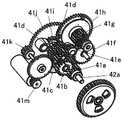
图5是表示齿轮机构的立体图。Fig. 5 is a perspective view showing a gear mechanism.
图6是从车辆玩具的左方观察齿轮机构的侧视图。Fig. 6 is a side view of the gear mechanism viewed from the left side of the vehicle toy.
图7是从车辆玩具的右方观察齿轮机构的侧视图。Fig. 7 is a side view of the gear mechanism viewed from the right side of the vehicle toy.
图8是从车辆玩具的右方观察行星齿轮机构的侧视图。Fig. 8 is a side view of the planetary gear mechanism viewed from the right side of the vehicle toy.
图9是表示离合器机构的分解立体图。Fig. 9 is an exploded perspective view showing a clutch mechanism.
图10是从车辆玩具的右方观察操作部件的侧视图。Fig. 10 is a side view of the operating member viewed from the right side of the vehicle toy.
图11是表示充放电电路的图。FIG. 11 is a diagram showing a charging and discharging circuit.
[附图标记说明][Description of Reference Signs]
10 先头车辆;10 lead vehicles;
10a 壳体;10a housing;
11 从动轮;11 driven wheels;
12 动轮;12 moving wheels;
13 配重;13 counterweight;
20 发电电动机;20 generator motor;
21 转子;21 rotor;
30 双电层电容;30 electric double layer capacitance;
40 齿轮机构;40 gear mechanism;
43 臂;43 arms;
45 行星齿轮机构;45 planetary gear mechanism;
50 操作部件;50 operating parts;
50a 臂限制片;50a arm restraint;
50b、50c 开关操作片;50b, 50c switch operation piece;
60 充放电电路;60 charge and discharge circuit;
60a 充电电路;60a charging circuit;
60b 放电电路;60b discharge circuit;
61 开关;61 switch;
61a 旋钮;61a knob;
100 车辆玩具。100 vehicle toys.
具体实施方式Detailed ways
以下,参照附图对本发明的实施方式进行说明。Hereinafter, embodiments of the present invention will be described with reference to the drawings.
图1是表示车辆玩具100的外观的立体图。图2是表示车辆玩具100的先头车辆10的内部的壳体10a的立体图,图3是表示将壳体10a的上部罩拆下后的状态的立体图,图4是表示向壳体10a组装的部件的立体图。FIG. 1 is a perspective view showing the appearance of a
车辆玩具100为3辆编组的铁道车辆玩具。在先头车辆10的内部的壳体10a的前部左右设置有从动轮11、11,在后部左右设置有动轮12、12。另外,如图4所示,在壳体10a的前部和后部设置有多个配重13。另外,在壳体10a设置有发电电动机20、双电层电容器30、齿轮机构40、操作部件50、以及连结器70(参照图2)。The
发电电动机20兼具发电机和电动机的功能,在作为电动机发挥功能时,通过蓄积在双电层电容器30中的电力使左右的动轮12、12旋转。另外,发电电动机20在作为发电机发挥功能时通过左右的动轮12、12的旋转对双电层电容器30进行充电。The
齿轮机构40连结发电电动机20和左右的动轮12、12,通过发电电动机20的动力经由齿轮机构40使左右的动轮12、12旋转,并且通过左右的动轮12、12的旋转经由齿轮机构40使发电电动机20动作。The
操作部件50使发电电动机20选择性地作为发电机或电动机发挥功能,并且与其相应地限制齿轮机构40中的齿轮的啮合。The operating
连结器70用于与其他车辆的连结。The
(齿轮机构40)(gear mechanism 40)
图5是表示齿轮机构40的立体图,图6是从车辆玩具100的左方观察齿轮机构40的侧视图,图7是从车辆玩具100的右方观察齿轮机构40的侧视图。5 is a perspective view showing the
将动轮12与发电电动机20连结的齿轮机构40构成为包括齿轮41a、41b、41c、…、41l、41m。The
齿轮41a固定于车轴42a,与动轮12一体地旋转。齿轮41b设置于与车轴42a平行的轴42b,且与齿轮41a啮合。齿轮41c和齿轮41d被设置为在与轴42b平行的轴42c上相互一体地旋转。其中,齿轮41c与齿轮41b啮合。The
齿轮41e构成将齿轮41d作为太阳齿轮的行星齿轮机构45(参照图6)。即,齿轮41e是行星齿轮,设置在以轴42c为中心转动的臂43的一端的轴42d上,且与齿轮41d啮合。齿轮41f设于与轴42c平行的轴42e,且在臂43的第一转动位置处与齿轮41e啮合。齿轮41g设置于与轴42e平行的轴42f,且与齿轮41f啮合。该齿轮41g在臂43的第二转动位置处与齿轮41e啮合。根据臂43依赖于齿轮41d的旋转方向的转动方向来选择性地进行齿轮41e与齿轮41f的啮合、齿轮41e与齿轮41g的啮合。The
齿轮41h设置于轴42f,经由离合器机构44(参照图9)而与所述齿轮41g连结。齿轮41i(参照图5)设置于轴42c,且与齿轮41h啮合。齿轮41j设置于轴41c,且与齿轮41i构成二级齿轮。齿轮41k固定设置于与轴42c平行的轴42g,且与齿轮41j啮合。齿轮41l固定设置于轴42g,且与齿轮41k一体地旋转。齿轮41m固定设置于与轴42g平行的转子轴21,且与齿轮41l啮合。The
需要说明的是,齿轮41h~齿轮41m在处于充电状态时构成增速齿轮系。It should be noted that the
而且,在该齿轮机构40中,在充电时(发电时)使动轮12向前进方向旋转的情况下的从动轮12向发电电动机20的动力传递经由齿轮41a、41b、41c、···、41e、41g、···、41l、41m来进行。另外,在充电时使轮12向后退方向旋转的情况下的从动轮12向发电电动机20的动力传递经由齿轮41a、41b、41c、···、41e、41f、···、41l、41m来进行。In addition, in this
另外,在放电时从发电电动机20向动轮12的动力传递经由41m、41l、···、41g、41e、···、41c、41b、齿轮41a来进行。In addition, power transmission from the
图8是表示行星齿轮机构45的图。FIG. 8 is a diagram showing the
行星齿轮机构45具备作为太阳齿轮的齿轮41d、作为行星齿轮的齿轮41e、以齿轮41d的轴42c为中心转动的臂43。臂43在长度方向中间部被轴43c支承。并且,在臂43的一端部经由轴42d安装有与齿轮41d啮合的齿轮41e。The
该行星齿轮机构45在处于充电状态时,若动轮12向前进方向旋转且齿轮41d向一个方向旋转,则被臂43支承的齿轮41e向一个方向公转而与齿轮41g啮合,另一方面,在处于充电状态时,若动轮12向后退方向旋转且齿轮41d向另一方向旋转,则齿轮41e向另一方向公转而与齿轮41f啮合。When the
图9是表示离合器机构44的立体图。离合器机构44具备:圆板44a,其能够与齿轮41g一体地沿轴42f的轴线方向移动;以及螺旋弹簧44b,其将圆板44a按压于齿轮41h。在齿轮41h的端面,以120°间隔形成有3个沿半径方向延伸的V槽44c。另一方面,在圆板44a上,以120°间隔形成有3个与V槽44c互补的形状的凸条44d。通过V槽44c与凸条44d卡合,进行齿轮41g与齿轮41f之间的动力传递,在过载作用的情况下,V槽44c与凸条44d的卡合被解除,齿轮41g与齿轮41f之间的动力传递被切断。FIG. 9 is a perspective view showing the
(充放电电路60)(charge and discharge circuit 60)
图11是表示充放电电路60的图。FIG. 11 is a diagram showing the charging and discharging
发电电动机20和双电层电容器30设置于充放电电路60。作为发电电动机20,没有特别限定,使用不产生齿槽效应的无芯电动机,以避免因通过转子铁心/磁铁间的磁吸引作用的所谓齿槽效应(cogging)导致在充电时起动静止状态的转子时产生的阻力、旋转时的振动变大。发电电动机20以外的充放电电路60的构成要素设置于基板67。The
充放电电路60具备充电电路60a和放电电路60b,充电电路60a和放电电路60b没有特别限定,能够通过作为3路开关的切换开关61进行切换。The charging and discharging
在充放电电路60中,与发电电动机20并联地设置有双电层电容器30、电阻63以及发光二极管64。而且,在双电层电容器30的充电进行而端子电压成为预定值以上时,发光二极管64点亮,另外,在充电电路60a中设置有二极管65,通过该二极管65防止电荷的逆流。In the charge and
(操作部件50)(operating part 50)
图10是从车辆玩具100的右方观察操作部件50的侧视图。FIG. 10 is a side view of the operating
操作部件50在壳体10a的前后方向上构成为长条状。操作部件50对所述臂43和切换开关61进行操作。The
在操作部件50的后部设置有向先头车辆10的车顶上突出的旋钮51,操作部件50能够通过旋钮51的操作而在前后方向上进行动作。A
在操作部件50的前后方向中间部设有臂限制片50a,臂限制片50a在操作部件50位于后方时不与臂43卡合,允许臂43的自由转动。另外,在操作部件50位于前方时,臂限制片50a将臂43的前端侧下压,将齿轮41e与齿轮41g保持为啮合状态。An
另外,在操作部件50的前端部设置有一对开关操作片50b、50c,在操作部件60位于后方时,通过开关操作片50c使切换开关61的旋钮61a向后方动作而使充电电路60a闭合,在操作部件50位于前方时,通过开关操作片50b使旋钮61a向前方动作,使放电电路60b闭合。In addition, a pair of
(玩法和动作)(play and action)
接着,对玩法和动作进行说明。Next, the gameplay and actions will be described.
首先,使操作部件50的旋钮50a向后方动作。由此,操作部件50向后方动作,臂限制片50a位于轴42c的上方。在该位置处,臂43成为能够自由转动的状态。另外,通过开关操作片50c,切换开关61的旋钮61a向后方动作,充电电路60a被闭合。First, the
在该状态下,在使先头车辆10接地的状态下前后移动。此时,若将先头车辆10向前方手推,则齿轮41e与齿轮41g啮合,另一方面,若将先头车辆10向前方手推,则齿轮41e与齿轮41f啮合,发电电动机20的转子向一个方向旋转,对双电层电容器30进行充电。当充电进行时,发光二极管64点亮。在该发光二极管64成为预定的亮度之前,使开先头车辆辆10在接地的状态下前后移动。In this state, the vehicle moves back and forth with the
然后,如果充电完成,则将先头车辆10单独地放置在轨道90(参照图1)上、或者将先头车辆10在与其他车辆连结的状态下放置在轨道90(参照图1)上,使操作部件50的旋钮50a向前方动作。由此,操作部件50向前方动作,臂限制片50a将臂43的前端侧下压,将齿轮41e与齿轮41g保持为啮合状态。另外,通过开关操作片50b,切换开关61的旋钮61a向前方动作,放电电路60b被闭合。Then, if charging is completed, the
由此,发电电动机20被驱动,动轮12、12向前进方向旋转。As a result, the
(实施方式的效果)(Effect of embodiment)
根据实施方式的车辆玩具100,能够得到如下的效果。According to the
根据本实施方式的车辆玩具100,在充电电路60a闭合时,行星齿轮41e向与动轮12、12的旋转方向相应的方向公转而与齿轮41g或齿轮41f啮合并与发电电动机20的转子连结,使转子向一个方向旋转,因此不需要在充放电电路60设置全波整流电路,能够减少电力损失。According to the
另外,由于使用双电层电容器30作为蓄电器件,因此能够在短时间内进行充电。In addition, since the electric
此外,在放电电路60b闭合时,在齿轮41g与行星齿轮41e啮合的位置处固定臂43,因此能够可靠地通过来自双电层电容器30的放电经由发电电动机20使动轮12、12向一个方向旋转。In addition, when the
另外,操作部件50同时操作切换开关61以及臂43,因此能够简单地进行充电状态和放电状态的切换。In addition, since the
另外,齿轮机构40在充电电路60a闭合时,在成为行星齿轮40的下游的位置处具备增速齿轮系,因此在充电状态下,在动轮12、12的旋转方向改变时,增速齿轮系的齿轮以及发电电动机20的旋转部起到飞轮那样的作用,因此能够提高充电效率。进而,通过增速齿轮系的齿轮及发电电动机的旋转部仅向一个方向旋转,也能够实现充电效率的提高。In addition, the
(变形例)(Modification)
在所述实施方式中,使用了双电层电容器作为蓄电器件,但也可以使用锂离子电容器等电容器、锂离子电池等充电电池。In the above-described embodiment, an electric double layer capacitor is used as the power storage device, but a capacitor such as a lithium ion capacitor or a rechargeable battery such as a lithium ion battery may also be used.
另外,在所述实施方式中,对铁道车辆玩具进行了说明,但不仅能够应用于机动车玩具及其他车辆玩具,还能够应用于利用车轮行驶的行驶玩具。In addition, in the above-mentioned embodiment, the railway vehicle toy was described, but it can be applied not only to a motor vehicle toy and other vehicle toys but also to a running toy that travels on wheels.
Claims (7)
Translated fromChineseApplications Claiming Priority (2)
| Application Number | Priority Date | Filing Date | Title |
|---|---|---|---|
| JP2021077463AJP7105340B1 (en) | 2021-04-30 | 2021-04-30 | running toy |
| JP2021-077463 | 2021-04-30 |
Publications (2)
| Publication Number | Publication Date |
|---|---|
| CN115253317Atrue CN115253317A (en) | 2022-11-01 |
| CN115253317B CN115253317B (en) | 2024-08-30 |
Family
ID=81566067
Family Applications (2)
| Application Number | Title | Priority Date | Filing Date |
|---|---|---|---|
| CN202111188914.1AActiveCN115253317B (en) | 2021-04-30 | 2021-10-12 | Running toy |
| CN202122455539.4UWithdrawn - After IssueCN216536886U (en) | 2021-04-30 | 2021-10-12 | Running toy |
Family Applications After (1)
| Application Number | Title | Priority Date | Filing Date |
|---|---|---|---|
| CN202122455539.4UWithdrawn - After IssueCN216536886U (en) | 2021-04-30 | 2021-10-12 | Running toy |
Country Status (2)
| Country | Link |
|---|---|
| JP (1) | JP7105340B1 (en) |
| CN (2) | CN115253317B (en) |
Families Citing this family (1)
| Publication number | Priority date | Publication date | Assignee | Title |
|---|---|---|---|---|
| JP7105340B1 (en)* | 2021-04-30 | 2022-07-22 | 株式会社タカラトミー | running toy |
Citations (8)
| Publication number | Priority date | Publication date | Assignee | Title |
|---|---|---|---|---|
| JP3111394U (en)* | 2004-12-24 | 2005-07-28 | 真生 佐々木 | Battery car with an eccentric mechanism |
| CN101347673A (en)* | 2007-07-20 | 2009-01-21 | 中国人民解放军第四军医大学 | artificial gravity simulator |
| CN201321120Y (en)* | 2008-11-10 | 2009-10-07 | 张仲甦 | Self-generating baby carriage structure |
| CN201755413U (en)* | 2009-10-13 | 2011-03-09 | 株式会社多美 | Toy of parking lot |
| CN202446727U (en)* | 2011-12-23 | 2012-09-26 | 桂林电子科技大学 | Fitness energy-accumulation stepper |
| JP2012223208A (en)* | 2011-04-14 | 2012-11-15 | Megahouse Corp | Driving unit and traveling toy |
| CN108970019A (en)* | 2018-10-19 | 2018-12-11 | 汪铮 | A kind of respiratory function training device |
| CN216536886U (en)* | 2021-04-30 | 2022-05-17 | 株式会社多美 | Running toy |
Family Cites Families (3)
| Publication number | Priority date | Publication date | Assignee | Title |
|---|---|---|---|---|
| JPH0631796U (en)* | 1992-09-30 | 1994-04-26 | 株式会社タカラ | Car toy |
| JP2004283476A (en)* | 2003-03-24 | 2004-10-14 | Izumi Toda | Manual power generation toy |
| US20140080380A1 (en)* | 2012-09-14 | 2014-03-20 | Mattel, Inc. | Toy Vehicle and Launcher |
- 2021
- 2021-04-30JPJP2021077463Apatent/JP7105340B1/enactiveActive
- 2021-10-12CNCN202111188914.1Apatent/CN115253317B/enactiveActive
- 2021-10-12CNCN202122455539.4Upatent/CN216536886U/ennot_activeWithdrawn - After Issue
Patent Citations (8)
| Publication number | Priority date | Publication date | Assignee | Title |
|---|---|---|---|---|
| JP3111394U (en)* | 2004-12-24 | 2005-07-28 | 真生 佐々木 | Battery car with an eccentric mechanism |
| CN101347673A (en)* | 2007-07-20 | 2009-01-21 | 中国人民解放军第四军医大学 | artificial gravity simulator |
| CN201321120Y (en)* | 2008-11-10 | 2009-10-07 | 张仲甦 | Self-generating baby carriage structure |
| CN201755413U (en)* | 2009-10-13 | 2011-03-09 | 株式会社多美 | Toy of parking lot |
| JP2012223208A (en)* | 2011-04-14 | 2012-11-15 | Megahouse Corp | Driving unit and traveling toy |
| CN202446727U (en)* | 2011-12-23 | 2012-09-26 | 桂林电子科技大学 | Fitness energy-accumulation stepper |
| CN108970019A (en)* | 2018-10-19 | 2018-12-11 | 汪铮 | A kind of respiratory function training device |
| CN216536886U (en)* | 2021-04-30 | 2022-05-17 | 株式会社多美 | Running toy |
Also Published As
| Publication number | Publication date |
|---|---|
| CN115253317B (en) | 2024-08-30 |
| JP2022171074A (en) | 2022-11-11 |
| CN216536886U (en) | 2022-05-17 |
| JP7105340B1 (en) | 2022-07-22 |
Similar Documents
| Publication | Publication Date | Title |
|---|---|---|
| TWI584974B (en) | Engine running at fixed speed incorporated controllable tnrasmission power system | |
| US5818134A (en) | Motor for motorcycles | |
| US3733744A (en) | Power module for driving vehicle-propelling element,including stationary axle means mounting said element | |
| CA2563378C (en) | Drive train for series/parallel hybrid vehicle | |
| WO2013089804A1 (en) | Electric vehicle with energy producing system and method of using the same | |
| JP5838582B2 (en) | Drive device for hybrid vehicle | |
| CN216536886U (en) | Running toy | |
| CN101837196B (en) | Inertia walking toy car and emitter for transmitting same | |
| CA2591392A1 (en) | Toy vehicle | |
| WO2001000988A1 (en) | Independent electric power systems of electrical cars | |
| CN105356541B (en) | A kind of charging equipment and its control method of mobile power source | |
| CN103316454B (en) | Self-generating exercise bike | |
| JP3165982U (en) | Pedal generator | |
| CN109833626B (en) | Toy car automatic gear box | |
| JP2004283476A (en) | Manual power generation toy | |
| CN2574750Y (en) | Pipe ball | |
| JP2012223208A (en) | Driving unit and traveling toy | |
| CN102447348B (en) | Hand driven generator with clutch | |
| KR200230387Y1 (en) | Portable power self-generator | |
| TW201938432A (en) | Hybrid driving system of remote control vehicle including a power generation module, a reducing gear set, a left power output shaft, a right power output shaft, a throttle switch set and a control module | |
| CN111600439B (en) | Flywheel power generation and supply system | |
| JPH07494U (en) | Toy using a generator | |
| CN112334347B (en) | Oil-electricity driving system of remote control carrier | |
| JP2012515868A (en) | Impeller device and automatic switching regeneration charging system using kinetic energy and wind energy | |
| CN100380772C (en) | Full-automatic cell phone charger |
Legal Events
| Date | Code | Title | Description |
|---|---|---|---|
| PB01 | Publication | ||
| PB01 | Publication | ||
| SE01 | Entry into force of request for substantive examination | ||
| SE01 | Entry into force of request for substantive examination | ||
| GR01 | Patent grant | ||
| GR01 | Patent grant |