CN115253063A - Drive mechanism and blood pump - Google Patents
Drive mechanism and blood pumpDownload PDFInfo
- Publication number
- CN115253063A CN115253063ACN202211072218.9ACN202211072218ACN115253063ACN 115253063 ACN115253063 ACN 115253063ACN 202211072218 ACN202211072218 ACN 202211072218ACN 115253063 ACN115253063 ACN 115253063A
- Authority
- CN
- China
- Prior art keywords
- groove
- opening
- rotating
- rotor
- assembly
- Prior art date
- Legal status (The legal status is an assumption and is not a legal conclusion. Google has not performed a legal analysis and makes no representation as to the accuracy of the status listed.)
- Pending
Links
Images


Classifications
- A—HUMAN NECESSITIES
- A61—MEDICAL OR VETERINARY SCIENCE; HYGIENE
- A61M—DEVICES FOR INTRODUCING MEDIA INTO, OR ONTO, THE BODY; DEVICES FOR TRANSDUCING BODY MEDIA OR FOR TAKING MEDIA FROM THE BODY; DEVICES FOR PRODUCING OR ENDING SLEEP OR STUPOR
- A61M60/00—Blood pumps; Devices for mechanical circulatory actuation; Balloon pumps for circulatory assistance
- A61M60/10—Location thereof with respect to the patient's body
- A61M60/122—Implantable pumps or pumping devices, i.e. the blood being pumped inside the patient's body
- A61M60/126—Implantable pumps or pumping devices, i.e. the blood being pumped inside the patient's body implantable via, into, inside, in line, branching on, or around a blood vessel
- A61M60/135—Implantable pumps or pumping devices, i.e. the blood being pumped inside the patient's body implantable via, into, inside, in line, branching on, or around a blood vessel inside a blood vessel, e.g. using grafting
- A—HUMAN NECESSITIES
- A61—MEDICAL OR VETERINARY SCIENCE; HYGIENE
- A61M—DEVICES FOR INTRODUCING MEDIA INTO, OR ONTO, THE BODY; DEVICES FOR TRANSDUCING BODY MEDIA OR FOR TAKING MEDIA FROM THE BODY; DEVICES FOR PRODUCING OR ENDING SLEEP OR STUPOR
- A61M60/00—Blood pumps; Devices for mechanical circulatory actuation; Balloon pumps for circulatory assistance
- A61M60/10—Location thereof with respect to the patient's body
- A61M60/122—Implantable pumps or pumping devices, i.e. the blood being pumped inside the patient's body
- A61M60/165—Implantable pumps or pumping devices, i.e. the blood being pumped inside the patient's body implantable in, on, or around the heart
- A61M60/17—Implantable pumps or pumping devices, i.e. the blood being pumped inside the patient's body implantable in, on, or around the heart inside a ventricle, e.g. intraventricular balloon pumps
- A61M60/174—Implantable pumps or pumping devices, i.e. the blood being pumped inside the patient's body implantable in, on, or around the heart inside a ventricle, e.g. intraventricular balloon pumps discharging the blood to the ventricle or arterial system via a cannula internal to the ventricle or arterial system
- A—HUMAN NECESSITIES
- A61—MEDICAL OR VETERINARY SCIENCE; HYGIENE
- A61M—DEVICES FOR INTRODUCING MEDIA INTO, OR ONTO, THE BODY; DEVICES FOR TRANSDUCING BODY MEDIA OR FOR TAKING MEDIA FROM THE BODY; DEVICES FOR PRODUCING OR ENDING SLEEP OR STUPOR
- A61M60/00—Blood pumps; Devices for mechanical circulatory actuation; Balloon pumps for circulatory assistance
- A61M60/20—Type thereof
- A61M60/205—Non-positive displacement blood pumps
- A61M60/216—Non-positive displacement blood pumps including a rotating member acting on the blood, e.g. impeller
- A—HUMAN NECESSITIES
- A61—MEDICAL OR VETERINARY SCIENCE; HYGIENE
- A61M—DEVICES FOR INTRODUCING MEDIA INTO, OR ONTO, THE BODY; DEVICES FOR TRANSDUCING BODY MEDIA OR FOR TAKING MEDIA FROM THE BODY; DEVICES FOR PRODUCING OR ENDING SLEEP OR STUPOR
- A61M60/00—Blood pumps; Devices for mechanical circulatory actuation; Balloon pumps for circulatory assistance
- A61M60/40—Details relating to driving
- A61M60/403—Details relating to driving for non-positive displacement blood pumps
- A61M60/422—Details relating to driving for non-positive displacement blood pumps the force acting on the blood contacting member being electromagnetic, e.g. using canned motor pumps
- A—HUMAN NECESSITIES
- A61—MEDICAL OR VETERINARY SCIENCE; HYGIENE
- A61M—DEVICES FOR INTRODUCING MEDIA INTO, OR ONTO, THE BODY; DEVICES FOR TRANSDUCING BODY MEDIA OR FOR TAKING MEDIA FROM THE BODY; DEVICES FOR PRODUCING OR ENDING SLEEP OR STUPOR
- A61M60/00—Blood pumps; Devices for mechanical circulatory actuation; Balloon pumps for circulatory assistance
- A61M60/80—Constructional details other than related to driving
- A61M60/855—Constructional details other than related to driving of implantable pumps or pumping devices
- A61M60/857—Implantable blood tubes
Landscapes
- Health & Medical Sciences (AREA)
- Heart & Thoracic Surgery (AREA)
- Engineering & Computer Science (AREA)
- Cardiology (AREA)
- Biomedical Technology (AREA)
- Mechanical Engineering (AREA)
- Anesthesiology (AREA)
- Hematology (AREA)
- Life Sciences & Earth Sciences (AREA)
- Animal Behavior & Ethology (AREA)
- General Health & Medical Sciences (AREA)
- Public Health (AREA)
- Veterinary Medicine (AREA)
- Vascular Medicine (AREA)
- Transplantation (AREA)
- Structures Of Non-Positive Displacement Pumps (AREA)
- External Artificial Organs (AREA)
Abstract
Translated fromChinese
Description
Translated fromChinese技术领域technical field
本发明涉及医疗器械技术领域,尤其是涉及一种驱动机构和血泵。The invention relates to the technical field of medical instruments, in particular to a driving mechanism and a blood pump.
背景技术Background technique
血泵被设计为经皮插入患者的血管中,例如大腿或腋窝的动脉或静脉的血管内,可以被前探入患者的心脏中以作为左心室辅助设备或右心室辅助设备起作用。因此,血泵也可以被称为心内血泵或血管内血泵。Blood pumps designed to be inserted percutaneously into a patient's blood vessel, such as an artery or vein in the thigh or armpit, can be advanced into the patient's heart to function as a left ventricular assist device or a right ventricular assist device. Therefore, the blood pump may also be referred to as an intracardiac blood pump or an intravascular blood pump.
通常血泵具有驱动机构和叶轮,叶轮与驱动机构的转动组件连接,为了实现转动组件的稳定转动,通常需要设置对转动组件进行定位或限位的结构,导致驱动机构的结构较为复杂。Generally, a blood pump has a driving mechanism and an impeller, and the impeller is connected to the rotating assembly of the driving mechanism. In order to achieve stable rotation of the rotating assembly, a structure for positioning or limiting the rotating assembly is usually required, resulting in a complicated structure of the driving mechanism.
发明内容Contents of the invention
本发明的目的在于提供一种结构较为简单的驱动机构及血泵。The purpose of the present invention is to provide a driving mechanism and a blood pump with a relatively simple structure.
一种驱动机构,所述驱动机构包括:A drive mechanism, the drive mechanism comprising:
壳体组件;shell components;
转动组件,所述转动组件具有远端和近端,所述转动组件的远端能够转动地安装于所述壳体组件,所述转动组件的近端开设有第一凹槽,所述第一凹槽具有内凹的第一球面壁;其中,所述壳体组件开设有第二凹槽,所述第二凹槽与所述第一凹槽相对设置,所述第二凹槽具有内凹的第二球面壁;以及A rotating assembly, the rotating assembly has a distal end and a proximal end, the distal end of the rotating assembly is rotatably mounted on the housing assembly, the proximal end of the rotating assembly is provided with a first groove, and the first The groove has a concave first spherical wall; wherein, the housing assembly is provided with a second groove, the second groove is opposite to the first groove, and the second groove has a concave The second spherical wall of ; and
球体,所述球体的一部分设置于所述第一凹槽内,一部分设置于所述第二凹槽内,所述球体分别与所述第一球面壁和所述第二球面壁滑动抵接。A sphere, a part of the sphere is arranged in the first groove, and a part is arranged in the second groove, and the sphere is in sliding contact with the first spherical wall and the second spherical wall respectively.
可选地,所述第一凹槽的靠近所述第二凹槽的开口边缘处和所述第二凹槽的靠近所述第一凹槽的开口边缘处均设置倒圆。Optionally, rounding is provided at the opening edge of the first groove close to the second groove and at the opening edge of the second groove close to the first groove.
可选地,所述球体的直径大于所述第一凹槽和所述第二凹槽在所述转动组件的转动轴线的长度之和。Optionally, the diameter of the sphere is greater than the sum of the lengths of the first groove and the second groove on the rotation axis of the rotating assembly.
可选地,所述第一凹槽沿所述转动组件的转动轴线的长度大于或等于所述球体的直径的1/4且小于所述球体的直径的1/2;Optionally, the length of the first groove along the rotation axis of the rotating assembly is greater than or equal to 1/4 of the diameter of the sphere and less than 1/2 of the diameter of the sphere;
和/或,所述第二凹槽沿所述转动组件的转动轴线的长度大于或等于所述球体的直径的1/4且小于所述球体的直径的1/2。And/or, the length of the second groove along the rotation axis of the rotating assembly is greater than or equal to 1/4 of the diameter of the sphere and less than 1/2 of the diameter of the sphere.
可选地,所述第二凹槽具有第一开口和第二开口,所述第一开口较所述第二开口更靠近所述第一凹槽,所述第一开口的中心轴线和所述第二开口的中心轴线重合,其中:Optionally, the second groove has a first opening and a second opening, the first opening is closer to the first groove than the second opening, the central axis of the first opening and the The central axes of the second opening coincide, wherein:
所述第二开口位于所述第二球面壁的中心位置;和/或,所述第二开口的口径为所述球体的直径的1/9-1/3。The second opening is located at the center of the second spherical wall; and/or, the diameter of the second opening is 1/9-1/3 of the diameter of the sphere.
可选地,所述壳体组件包括泵壳和安装于所述泵壳的支撑件,所述第二凹槽开设于所述支撑件上,所述驱动机构还包括支撑座,所述支撑座固接于所述泵壳,所述支撑座上开设有安装腔和与所述安装腔连通的通液孔,所述支撑件安装于所述安装腔中,所述第二凹槽与所述通液孔连通。Optionally, the casing assembly includes a pump casing and a support installed on the pump casing, the second groove is opened on the support, and the driving mechanism further includes a support seat, and the support seat Fixed to the pump casing, the support seat is provided with an installation cavity and a liquid hole communicating with the installation cavity, the support is installed in the installation cavity, the second groove is connected to the The liquid hole is connected.
可选地,所述安装腔具有腔底,所述通液孔的一个开口位于所述腔底,所述安装腔内设有支撑台阶,所述支撑台阶与所述支撑件抵接,以使所述支撑件与所述腔底间隔一段距离;Optionally, the installation cavity has a cavity bottom, an opening of the liquid hole is located at the bottom of the cavity, and a support step is provided in the installation cavity, and the support step is in contact with the support member, so that The support is spaced a distance from the cavity bottom;
和/或,所述支撑座还开设有分流道,所述分流道与所述通液孔连通,以使进入所述通液孔的流体还能够通过所述分流道流入所述泵壳;And/or, the support seat is further provided with a flow channel, and the flow channel communicates with the liquid hole, so that the fluid entering the liquid hole can also flow into the pump casing through the flow channel;
和/或,所述第二凹槽具有第一开口和第二开口,所述第一开口与所述第一凹槽相对,所述第二开口与所述通液孔连通,所述支撑件还开设有连通孔,所述连通孔连通所述第二开口和所述通液孔,所述连通孔沿所述第一开口的中心轴线具有一定长度。And/or, the second groove has a first opening and a second opening, the first opening is opposite to the first groove, the second opening communicates with the liquid hole, and the support member A communication hole is also provided, the communication hole communicates with the second opening and the liquid hole, and the communication hole has a certain length along the central axis of the first opening.
可选地,所述壳体组件包括泵壳和轴套,所述轴套安装于所述泵壳,所述转动组件的远端能够转动地穿设于所述轴套,所述驱动机构还包括止挡件,所述止挡件与所述转动组件固接,所述止挡件位于所述轴套和所述球体之间,所述止挡件能够与所述轴套抵接,以阻止所述转动组件朝远离所述球体的方向移动。Optionally, the casing assembly includes a pump casing and a shaft sleeve, the shaft sleeve is mounted on the pump casing, the distal end of the rotating assembly is rotatably passed through the shaft sleeve, and the drive mechanism also A stopper is included, the stopper is fixedly connected to the rotating assembly, the stopper is located between the shaft sleeve and the sphere, the stopper can abut against the shaft sleeve, and The rotating assembly is prevented from moving in a direction away from the sphere.
可选地,所述轴套开设有轴孔,所述转动组件能够转动地穿设于所述轴孔,所述轴套的朝向所述止挡件的一面局部凹陷形成导流槽,所述导流槽与所述轴孔连通;所述止挡件与所述轴套抵接时,部分所述导流槽未被所述止挡件覆盖;Optionally, the shaft sleeve is provided with a shaft hole, and the rotating assembly is rotatably passed through the shaft hole, and the side of the shaft sleeve facing the stopper is partially recessed to form a flow guide groove, and the The diversion groove communicates with the shaft hole; when the stopper abuts against the bushing, part of the diversion groove is not covered by the stopper;
和/或,所述轴套开设有第三凹槽,所述第三凹槽具有内凹的第三球面壁,所述止挡件具有外凸的止挡面,所述止挡面能够与所述第三球面壁抵接。And/or, the bushing is provided with a third groove, the third groove has a concave third spherical wall, the stopper has a convex stop surface, and the stop surface can be in contact with The third spherical wall abuts.
可选地,所述转动组件包括转轴和转子,所述转轴具有近端和远端,所述转轴的远端能够转动地安装于所述壳体组件,所述转子包括第一转子单元,所述第一转子单元固接于所述转轴的近端,所述第一凹槽开设于所述第一转子单元上。Optionally, the rotating assembly includes a rotating shaft and a rotor, the rotating shaft has a proximal end and a distal end, the distal end of the rotating shaft is rotatably mounted on the housing assembly, the rotor includes a first rotor unit, the The first rotor unit is fixedly connected to the proximal end of the rotating shaft, and the first groove is opened on the first rotor unit.
可选地,所述转子还包括第二转子单元,所述第二转子单元固接于所述转轴,并靠近所述转轴的远端设置,所述驱动机构还包括定子,所述定子包括沿所述转轴的轴线设置的第一定子单元和第二定子单元,所述第一定子单元和所述第二定子单元均位于所述第一转子单元和所述第二转子单元之间,所述第一定子单元能够驱动所述第一转子单元转动,所述第二定子单元能够驱动所述第二转子单元转动;所述第一定子单元和所述第二定子单元均包括磁芯和线圈,所述线圈缠绕于所述磁芯上;Optionally, the rotor further includes a second rotor unit, the second rotor unit is fixed to the shaft and arranged near the far end of the shaft, the drive mechanism further includes a stator, and the stator includes a a first stator unit and a second stator unit arranged on the axis of the rotating shaft, the first stator unit and the second stator unit are both located between the first rotor unit and the second rotor unit, The first stator unit can drive the first rotor unit to rotate, and the second stator unit can drive the second rotor unit to rotate; both the first stator unit and the second stator unit include magnetic a core and a coil, the coil being wound on the core;
所述驱动机构还包括连接于所述壳体组件的导磁件,所述第一定子单元的所述磁芯和所述第二定子单元的所述磁芯均与所述导磁件固接,所述转轴能够转动地穿设于所述第一定子单元、所述第二定子单元和所述导磁件。The driving mechanism also includes a magnetically conductive member connected to the housing assembly, the magnetic core of the first stator unit and the magnetic core of the second stator unit are fixed with the magnetically conductive member Then, the rotating shaft is rotatably passed through the first stator unit, the second stator unit and the magnetic guide member.
一种血泵,包括叶轮及上述任一种驱动机构,所述叶轮与所述转动组件连接,所述叶轮能够随所述转动组件转动。A blood pump includes an impeller and any one of the above driving mechanisms, the impeller is connected with the rotating assembly, and the impeller can rotate with the rotating assembly.
由于转动组件的远端能够转动地安装于壳体组件,球体能够部分活动地置于转动组件的第一凹槽和壳体组件的第二凹槽之间中,并与第一球面壁和第二球面壁滑动抵接,从而通过球体和第一凹槽、第二凹槽的共同配合,以对转动组件的近端进行支撑和限位;同时由于球体的径向滚动路径被第一凹槽和第二凹槽内所限制,从而对转动组件的径向摆动范围进行限制;最后由于球体、转动组件和壳体组件相互独立,在装配过程中,只需要使转动组件的转动轴线与第一球面壁围设成的腔体的中心轴线重合,球体的一部分置于第一凹槽中即可保证球体的中心轴线与转动组件的转动轴线重合,再将壳体组件与球体配合,第二凹槽只需要起到支撑球体和限位的作用,无需再使第二球面壁的壁围设成的腔体的中心轴线与球体的中心轴线重合,降低了装配难度。Since the distal end of the rotating assembly is rotatably mounted on the housing assembly, the ball can be partially movably placed between the first groove of the rotating assembly and the second groove of the housing assembly, and is in contact with the first spherical wall and the second groove. The two spherical walls slide and abut, so that the proximal end of the rotating assembly is supported and limited by the cooperation of the ball, the first groove and the second groove; at the same time, the radial rolling path of the ball is controlled by the first groove and the second groove, so as to limit the radial swing range of the rotating assembly; finally, because the ball, rotating assembly and housing assembly are independent of each other, during the assembly process, only the rotation axis of the rotating assembly needs to be aligned with the first The central axis of the cavity surrounded by the spherical wall coincides, and a part of the sphere is placed in the first groove to ensure that the central axis of the sphere coincides with the rotation axis of the rotating assembly, and then the shell assembly is matched with the sphere, and the second recess The groove only needs to support the sphere and limit the position, and it is not necessary to make the central axis of the cavity surrounded by the second spherical wall coincide with the central axis of the sphere, which reduces the difficulty of assembly.
附图说明Description of drawings
为了更清楚地说明本发明实施例中的技术方案,下面将对实施例或现有技术描述中所需要使用的附图作简单地介绍,显而易见地,下面描述中的附图仅仅是本发明的一些实施例,对于本领域普通技术人员来讲,在不付出创造性劳动性的前提下,还可以根据这些附图获得其他的附图。In order to more clearly illustrate the technical solutions in the embodiments of the present invention, the following will briefly introduce the accompanying drawings that need to be used in the descriptions of the embodiments or the prior art. Obviously, the accompanying drawings in the following descriptions are only of the present invention. For some embodiments, those skilled in the art can also obtain other drawings according to these drawings without paying creative efforts.
图1为本发明实施例提供的血泵的结构示意图;FIG. 1 is a schematic structural diagram of a blood pump provided by an embodiment of the present invention;
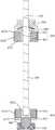
图2为图1所示的血泵省略了叶轮、定子、套管和部分导管的剖视图;Fig. 2 is a cross-sectional view of the blood pump shown in Fig. 1 omitting the impeller, stator, sleeve and part of the conduit;
图3为图1中的血泵的转轴、止挡件、转子、轴套、球体和支撑件组装在一起的剖视图;Fig. 3 is a cross-sectional view of the assembled rotating shaft, stopper, rotor, bushing, sphere and support of the blood pump in Fig. 1;
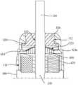
图4为图2所示的I部的局部放大图;Fig. 4 is a partial enlarged view of part I shown in Fig. 2;
图5为图1所示的血泵的转子、定子和导磁件的组装在一起的结构示意图;Fig. 5 is a schematic diagram of the assembled structure of the rotor, the stator and the magnetic conducting part of the blood pump shown in Fig. 1;
图6为图2所示的转子的第一转子单元的第一飞轮的结构示意图;Fig. 6 is a structural schematic diagram of a first flywheel of the first rotor unit of the rotor shown in Fig. 2;
图7为图6所示的第二定子单元和导磁件的一个导磁板组装在一起的结构示意图;Fig. 7 is a structural schematic diagram of the assembly of the second stator unit shown in Fig. 6 and a magnetically conductive plate of the magnetically conductive member;
图8为图2所示的血泵的支撑件的结构示意图;Fig. 8 is a schematic structural diagram of the support member of the blood pump shown in Fig. 2;
图9为图8所示的支撑件的剖面结构示意图;Fig. 9 is a schematic cross-sectional structure diagram of the support shown in Fig. 8;
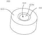
图10为图2中的第一飞轮的结构示意图;Fig. 10 is a schematic structural view of the first flywheel in Fig. 2;
图11为图2所示的血泵的止挡件的结构示意图;Fig. 11 is a schematic structural diagram of the stopper of the blood pump shown in Fig. 2;
图12为图1所示的血泵省略了部分导管的另一角度的剖视图;Fig. 12 is a cross-sectional view of the blood pump shown in Fig. 1 from another angle, omitting part of the catheter;
图13为图12的II部的局部放大图;Fig. 13 is a partially enlarged view of part II of Fig. 12;
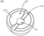
图14为图12所示的血泵的支撑座的结构示意图;Fig. 14 is a schematic structural view of the support seat of the blood pump shown in Fig. 12;
图15为图2所示的血泵的局部放大图;Fig. 15 is a partially enlarged view of the blood pump shown in Fig. 2;
图16为图2所示的血泵的轴套的局部放大图。Fig. 16 is a partially enlarged view of the shaft sleeve of the blood pump shown in Fig. 2 .
具体实施方式Detailed ways
下面详细描述本发明的实施例,所述实施例的示例在附图中示出,其中自始至终相同或类似的标号表示相同或类似的元件或具有相同或类似功能的元件。下面通过参考附图描述的实施例是示例性的,旨在用于解释本发明,而不能理解为对本发明的限制。Embodiments of the present invention are described in detail below, examples of which are shown in the drawings, wherein the same or similar reference numerals designate the same or similar elements or elements having the same or similar functions throughout. The embodiments described below by referring to the figures are exemplary and are intended to explain the present invention and should not be construed as limiting the present invention.
在整个说明书中参考“一个实施例”或“实施例”意味着结合实施例描述的特定特征,结构或特性包括在本申请的至少一个实施例中。因此,“在一个实施例中”或“在一些实施例中”的短语出现在整个说明书的各个地方,并非所有的指代都是相同的实施例。此外,在一个或多个实施例中,可以以任何合适的方式组合特定的特征,结构或特性。Reference throughout this specification to "one embodiment" or "an embodiment" means that a particular feature, structure or characteristic described in connection with the embodiment is included in at least one embodiment of the present application. Thus, the phrases "in one embodiment" or "in some embodiments" appear in various places throughout the specification, not all referring to the same embodiments. Furthermore, the particular features, structures or characteristics may be combined in any suitable manner in one or more embodiments.
在本发明的描述中,需要理解的是,术语“长度”、“宽度”、“上”、“下”、“前”、“后”、“左”、“右”、“竖直”、“水平”、“顶”、“底”“内”、“外”等指示的方位或位置关系为基于附图所示的方位或位置关系,仅是为了便于描述本发明和简化描述,而不是指示或暗示所指的装置或元件必须具有特定的方位、以特定的方位构造和操作,因此不能理解为对本发明的限制。In describing the present invention, it should be understood that the terms "length", "width", "upper", "lower", "front", "rear", "left", "right", "vertical", The orientation or positional relationship indicated by "horizontal", "top", "bottom", "inner", "outer", etc. are based on the orientation or positional relationship shown in the drawings, and are only for the convenience of describing the present invention and simplifying the description, rather than Nothing indicating or implying that a referenced device or element must have a particular orientation, be constructed, and operate in a particular orientation should therefore not be construed as limiting the invention.
此外,术语“第一”、“第二”仅用于描述目的,而不能理解为指示或暗示相对重要性或者隐含指明所指示的技术特征的数量。由此,限定有“第一”、“第二”的特征可以明示或者隐含地包括一个或者更多个该特征。In addition, the terms "first" and "second" are used for descriptive purposes only, and cannot be interpreted as indicating or implying relative importance or implicitly specifying the quantity of indicated technical features. Thus, a feature defined as "first" and "second" may explicitly or implicitly include one or more of these features.
在本发明中,除非另有明确的规定和限定,术语“安装”、“相连”、“连接”、“固定”等术语应做广义理解,例如,可以是固定连接,也可以是可拆卸连接,或成一体;可以是机械连接,也可以是电连接;可以是直接相连,也可以通过中间媒介间接相连,可以是两个元件内部的连通或两个元件的相互作用关系。对于本领域的普通技术人员而言,可以根据具体情况理解上述术语在本发明中的具体含义。In the present invention, unless otherwise clearly specified and limited, terms such as "installation", "connection", "connection" and "fixation" should be understood in a broad sense, for example, it can be a fixed connection or a detachable connection , or integrated; it can be mechanically connected or electrically connected; it can be directly connected or indirectly connected through an intermediary, and it can be the internal communication of two components or the interaction relationship between two components. Those of ordinary skill in the art can understand the specific meanings of the above terms in the present invention according to specific situations.
在介入医疗领域,通常定义器械距操作者近的一端为近端,距操作者远的一端为远端。In the field of interventional medicine, the end of the instrument that is closest to the operator is usually defined as the proximal end, and the end that is far from the operator is the distal end.
现对本发明实施例中的驱动机构10及血泵1进行说明。Now, the
请参考图1,血泵1包括驱动机构10和叶轮20。驱动机构10与叶轮20传动连接,驱动机构10能够驱动叶轮20转动。Please refer to FIG. 1 , a
具体地,血泵1还包括套管40,套管40固接于驱动机构10的远端。叶轮20能够转动地收容于套管40中。其中,套管40具有血液出口42和血液入口41。叶轮20转动时,血液从血液入口41流入套管40中,再从血液出口42流出。在一个实施例中,套管40延伸穿设于心脏瓣膜,诸如主动脉瓣膜,血液入口41位于心脏内,血液出口42和驱动机构10位于心脏外的诸如主动脉的血管中。Specifically, the
具体地,血泵1还包括导管50,导管50与驱动机构10的近端连接。其中,导管50用于容置各种供应管线。例如,供应管线包括用于与驱动机构10电连接的导线以及用于给血泵1通入冲洗液的冲洗管线。可选地,冲洗液为生理盐水、含有肝素生理盐水或葡萄糖等。Specifically, the
请结合图2至图7,驱动机构10包括泵壳100、转轴200、转子400、支撑件510、轴套520和球体900。泵壳100、轴套520和支撑件510构成壳体组件;转轴200和转子400构成转动组件;转动组件能够转动地安装于壳体组件,转动组件用于与叶轮20连接,以带动叶轮20转动。转动组件具有远端和近端,转动组件的远端能够转动地安装于壳体组件。其中,转动组件的近端开设有第一凹槽4124,第一凹槽4124具有内凹的第一球面壁4124a。壳体组件开设有第二凹槽512,第二凹槽512具有内凹的第二球面壁514,第二凹槽512与第一凹槽4124相对设置。球体900的一部分设置于第一凹槽4124内,并与第一球面壁4124a滑动抵接,球体900的一部分设置于第二凹槽512中,并与第二球面壁514滑动抵接,从而对球体900进行限位和支撑,通过球体900和第一凹槽4124、第二凹槽512的共同配合,以对转动组件的近端进行支撑和限位。同时由于球体900的径向滚动路径被第一凹槽4124和第二凹槽512内所限制,从而对转动组件的径向摆动范围进行限制;最后由于球体900、转动组件和壳体组件相互独立,在装配过程中,只需要使转动组件的转动轴线与第一球面壁4124a围设成的腔体的中心轴线重合,球体900的置于第一凹槽4124中即可保证球体900的中心轴线与转动组件的转动轴线重合,再将壳体组件与球体900配合,第二凹槽512只需要起到对球体900的支撑和限位作用,无需再使第二球面壁514围设成的腔体的中心轴线与球体900的中心轴线重合,降低了装配难度。Please refer to FIG. 2 to FIG. 7 , the
泵壳100大致为两端开口的筒状结构。泵壳100的远端与套管40固接,近端与导管50固接。泵壳100具有内腔。具体地,内腔分为限位腔112和容置腔114。在图示的实施例中,限位腔112和容置腔114沿泵壳100的轴向设置。The
转轴200能够转动地安装于泵壳100,转轴200具有用于与叶轮20连接的连接端210。在图示的实施例中,转轴200大致沿泵壳100的轴向延伸,或者说,转轴200的轴线的延伸方向与泵壳100的轴向大致一致。限位腔112和容置腔114沿转轴200的轴线设置。转轴200穿设于限位腔112,部分收容于容置腔114,部分位于泵壳100外或者说部分延伸至套管10内。转轴200的延伸至泵壳100外或者延伸至套管10中的部分为转轴200的连接端210;具体地,叶轮20与连接端210固接,以使叶轮20能够随转轴200转动。The
转子400位于泵壳100中,即转子400也设置在泵壳100的内腔中。在图示的实施例中,转子400位于容置腔114内。转子400固接于转轴200。其中,第一凹槽4124位于转轴200和转子400中的一个上。The rotor 400 is located in the
驱动机构10还包括定子300,定子300能够驱动转动组件转动。具体地,定子300能够驱动转子400转动,转子400能够带动转轴200转动。更具体地,转子400具有磁性,定子300能够产生驱动转子400转动的旋转磁场。定子300固定地安装于泵壳100,即定子300设置在泵壳100的内腔中。在图示的实施例中,定子300位于容置腔114中。其中,转轴200能够转动地穿设于定子300。The
请一并结合图5,在图示的实施例中,转子400包括第一转子单元410和第二转子单元420,第一转子单元410和第二转子单元420均固接于转轴200。第一转子单元410和第二转子单元420均能够转动地收容于泵壳100的容置腔114内。第一转子单元420和第二转子单元420沿转轴200的轴线设置。其中,定子300位于第一转子单元410和第二转子单元420之间。第一转子单元410和第二转子单元420均具有磁性,定子300能够产生驱动第一转子单元410和第二转子单元420转动的旋转磁场。Please refer to FIG. 5 together. In the illustrated embodiment, the rotor 400 includes a
具体地,第一转子单元410包括第一磁体411,第一磁体411与转轴200固接。其中,第一磁体411为环状的海尔贝克阵列磁铁。Specifically, the
具体地,第一转子单元410还包括第一飞轮412,第一飞轮412固接于转轴200,第一磁体411固接于第一飞轮412上。通过设置第一飞轮412可以增强第一磁体411与转轴200的连接强度;另外还能够减少转轴200在转动过程中的晃动,使整个转轴200在转动过程中更加稳定。在图示的实施例中,第一凹槽4124位于第一转子单元410上,具体为位于第一飞轮412上。Specifically, the
请一并结合图6,具体地,第一飞轮412包括第一内置管4121、第一盘状部4122和第一外环壁4123,第一内置管4121和第一外环壁4123两者均为圆管状结构,第一盘状部4122为环形圆盘结构。第一内置管4121和第一外环壁4123均与第一盘状部4122固接。第一外环壁4123环绕第一盘状部4122设置,第一内置管4121和第一外环壁4123两者同轴设置,转轴200套设于第一内置管4121中、并与第一内置管4121固定连接。第一内置管4121和第一外环壁4123之间形成有第一环形腔4124。第一磁体411容置在第一环形腔4124中。第一环形腔4124的形状与第一磁体411相适配,以方便第一磁体411的安装和定位。如此设置能够使第一飞轮412对第一磁体411起到限位作用,不仅方便第一磁体411的安装,而且也使得第一磁体411和第一飞轮412结合更加稳固。Please combine with FIG. 6 , specifically, the
请一并结合图10,第一凹槽4124设置在第一盘状部4122的中心,第一内置管4121也设置在第一盘状部4122的中心,或者说,第一凹槽4124的中心轴线和第一内置管4121的中心轴线重合。在本实施例中,转轴200的近端收容于第一内置管4121中、并与第一内置管4121固定连接,但不穿出于第一盘状部4122,如此可便于转轴200和第一转子单元410的装配和定位。转轴200的中心轴线和第一内置管4121的中心轴线重合。Please combine with FIG. 10, the
需要说明的是,第一飞轮412不限于为上述结构,在一些实施例中,第一飞轮412不具有第一外环壁4123;在一些实施例中,第一飞轮412不具有第一外环壁4123和第一内置管4121,此时,转轴200固定地穿设于第一盘状部4122的中心,第一凹槽4124可设置在转轴200的近端的端部。相对于仅具有第一盘状部4122的第一飞轮412,设置第一内置管4121能够使第一飞轮412与转轴200更加稳定地连接。It should be noted that the
第二转子单元420包括第二磁体421,第二磁体421固接于转轴200。具体地,第二磁体421为环状的海尔贝克阵列磁铁。The
具体地,第二转子单元420还包括第二飞轮422,第二飞轮422固接于转轴200上,第二磁体421固定于第二飞轮422。通过设置第二飞轮422可以增强第二磁体421与转轴200的连接强度;另外还能够减少转轴200在转动过程中的晃动,使整个转轴200在转动过程中更加稳定。Specifically, the
具体地,参阅图3,第二飞轮422包括第二内置管4221、第二盘状部4222和第二外环壁4223,第二内置管4221和第二外环壁4223两者均为圆管状结构,第二盘状部4222为环形圆盘结构。第二内置管4221和第二外环壁4223均与第二盘状部4222固接。第二外环壁4223环绕第二盘状部4222设置,第二内置管4221和第二外环壁4223两者同轴设置,转轴200穿设于第二内置管4221中、并与第二内置管4221固定连接。第二内置管4221和第二外环壁4223之间形成有第二环形腔。第二磁体421容置在第二环形腔中。第二环形腔的形状与第二磁体421相适配,以方便第二磁体421的安装和定位。如此设置能够使第二飞轮422对第二磁体421起到限位作用,不仅方便第二磁体421的安装,而且也使得第二磁体421和第二飞轮422结合更加稳固。Specifically, referring to FIG. 3 , the
需要说明的是,第二飞轮422不限于为上述结构,在一些实施例中,第二飞轮422不具有第二外环壁4223;在一些实施例中,第二飞轮422不具有第二外环壁4223和第二内置管4221,此时,转轴200固定地穿设于第二盘状部4222的中心。相对于仅具有第二盘状部4222的第二飞轮422,设置第二内置管4221能够使第二飞轮422与转轴200更加稳定地连接。It should be noted that the
具体地,定子300包括沿转轴200的轴线设置的第一定子单元310和第二定子单元320,第一定子单元310能够驱动第一转子单元410转动,第二定子单元320能够驱动第二转子单元420转动。具体地,第一定子单元310能够产生驱动第一转子单元410转动的旋转磁场,第二定子单元320能够产生驱动第二转子单元420转动的旋转磁场。第一定子单元310和第二定子单元320均固定地收容于泵壳100的容置腔114内。转轴200能够转动地穿设于第一定子单元310和第二定子单元320。其中,第一定子单元310和第二定子单元320均位于第一转子单元410和第二转子单元420之间。Specifically, the
其中,第一定子单元310和第二定子单元320均包括磁芯和线圈,线圈缠绕于磁芯上。具体地,第一定子单元310包括第一磁芯312和第一线圈313,第一线圈313缠绕于第一磁芯312上。第一磁芯312为多个,多个第一磁芯312环绕转轴200的轴线设置一周。每个第一磁芯312设有一个第一线圈313。Wherein, both the
第二定子单元320的结构与第一定子单元310的结构相似。请一并结合图8,第二定子单元320包括第二磁芯322和第二线圈323,第二线圈323缠绕于第二磁芯322上。第二磁芯322为多个,多个第二磁芯322环绕转轴200的轴线设置一周。每个第二磁芯322设有一个第二线圈323。The structure of the
具体地,驱动机构10还包括连接于泵壳100的导磁件700,第一定子单元310的第一磁芯312和第二定子单元320的第二磁芯322均与导磁件700固接。具体地,导磁件700固定地收容于泵壳100内,例如卡接、焊接或粘结于泵壳100的内侧壁。转轴200能够转动地穿设于导磁件700。第一磁芯312的一端与导磁件700固接,第一转子单元410靠近第一磁芯312的另一端设置;第二磁芯423的一端与导磁件700固接,第二转子单元420靠近第二磁芯322的另一端设置。Specifically, the
导磁件700起到闭合磁路的作用,以促进和增加磁通量的产生,提高耦合能力,因此,设置导磁件700能够起到闭合第一定子单元310和第一转子单元410之间的磁路的作用、闭合第二定子单元320和第二转子单元420之间的磁路的作用,增加磁通量,因此,导磁件700的设置有利于减小驱动机构10的整体直径。另外,将第一定子单元310的第一磁芯312和第二定子单元320的第二磁芯322均与导磁件700固接,还能够实现第一定子单元310和第二定子单元320的定位和安装,降低了第一定子单元310和第二定子单元320的装配难度。同时,上述方式设置的导磁件700还能够减少泵壳100内的定位结构的设置,从而简化泵壳100的结构,简化整个驱动机构10的装配过程。The
具体地,导磁件700包括两个导磁板710,两个导磁板710层叠,其中一个磁板710与第一定子单元310的第一磁芯312固接,另一个导磁板710与第二定子单元320的第二磁芯322固接,转轴200能够转动地穿设于两个导磁板710。具体地,两个导磁板710在装配之前为分体式,通过将导磁件700设置成在装配前为分体的两个导磁板710,在装配驱动机构10时,可以先将第一磁芯312固接于导磁板710,第二磁芯322固接于另一个导磁板710,然后将两个导磁板710层叠,如此,能够方便第一磁芯312和第二磁芯322分别装配至两个导磁板710,能够使第一磁芯321和第二磁芯322装配更加方便。Specifically, the magnetically
具体地,通过将两个导磁板710固接以使得第一定子单元310、第二定子单元320和导磁件700形成一个整体而装配至泵壳100内,使得定子300的装配更加容易。例如,两个导磁板710可以通过胶黏或焊接的方式连接在一起。可以理解,在其他实施例中,两个导磁板710没有固接,而是相互接触。Specifically, by fixing the two magnetically
需要说明的是,导磁件700不限于上述由两个分体的导磁板710组合而成的方式,导磁件700还可以为一板状结构,第一磁芯231和第二磁芯241均连接于导磁件700,即第一定子单元310和第二定子单元320共用一个导磁件700。It should be noted that the magnetic
具体地,导磁板710的材质为硅钢,第一磁芯312和第二磁芯322的材质为硅钢。Specifically, the material of the magnetic
球体900能够活动地收容于泵壳100。具体地,球体900位于容置腔114内。The
请再次结合图2、图3和图4,支撑件510和轴套520均安装于泵壳100内。具体地,支撑件510收容于容置腔114内,轴套520收容于限位腔112内。支撑件510和轴套520均固接于泵壳100。支撑件510、轴套520和球体900沿泵壳100的轴向设置,支撑件510、轴套520和球体900能够共同对转动组件进行限位。轴套520较支撑件510更靠近转轴200的连接端210。转子400位于球体900和轴套520之间;定子300也位于球体900和轴套520之间。在图示的实施例中,第一转子单元410、第二转子单元420、第一定子单元310和第二定子单元320均位于球体900和轴套520之间;球体900位于第一转子单元410和支撑件510之间;第一转子单元410靠近球体900设置,第二转子单元420靠近轴套520设置。换而言之,支撑件510、球体900、第一转子单元410、第一定子单元310、第二定子单元320、第二转子单元420和轴套520沿转轴200的轴线依次设置,其中,轴套520最靠近转轴200的连接端210。第二凹槽512开设于支撑件510上。Please refer to FIG. 2 , FIG. 3 and FIG. 4 again, the
请一并结合图8、图9和图10,具体地,第一凹槽4124的靠近第二凹槽512的开口边缘处和第二凹槽512的靠近第一凹槽4124的开口边缘处均设置倒圆515。由于转轴200在转动过程中,远离连接端210的第一转子单元410会发生小幅度径向偏摆,会带动球体900在第一凹槽4124和第二凹槽512内径向滚动,即设置了倒圆515以避免球体900被具有棱角的第一凹槽4124的开口边缘和第二凹槽512的开口边缘所刮伤和磨损。Please combine Figure 8, Figure 9 and Figure 10 together, specifically, the opening edge of the
具体地,球体900的直径大于第一凹槽4124和第二凹槽512沿转动组件的转动轴线(转动组件在没有发生径向摆动时)的长度之和,以使转动组件的近端和壳体组件(例如支撑件510)间隔一段距离,避免转动组件在发生径向摆动时转动组件的近端和壳体组件碰触。如图4所示,L1为第一凹槽4124的沿转动组件的转动轴线的长度,L2为第二凹槽512的沿转动组件的转动轴线(转动组件在没有发生径向摆动时)的长度,具体地,L2为第二凹槽512沿泵壳100的轴向的长度。球体900的部分位于第一凹槽4124和第二凹槽512外,第一凹槽4124的靠近第二凹槽512的一侧的开口和第二凹槽512的靠近第一凹槽4124的一侧的开口彼此间隔一段距离,即使得转子400(具体为第一转子单元410)和支撑件510之间间隔一段距离,避免转子400直接与支撑件510之间发生摩擦和磨损。Specifically, the diameter of the
更具体地,第一凹槽4124沿转动组件的转动轴线上的长度L1大于或等于球体900的直径的1/4且小于球体900的直径的1/2。如此,使球体900与第一凹槽4124的接触面积在此范围内,保证球体900与第一球面壁4124a之间的磨损在合理范围内。如小于球体900的直径的1/4,则球体900与第一球面壁4124a之间接触面积太小,造成的磨损太大;如大于球体900的直径的1/2,同时球体900进入第一凹槽4124的深度太深,其径向限位太牢固,第一球面壁4124a的坡度太陡,球体900的径向滚动困难,造成适应偏摆能力下降,导致转动组件转动不畅甚至卡死。同时,在图示实施例中,由于第一凹槽4124开设在第一盘状部4122的远离第一磁体411的一侧面上,若第一凹槽4124的深度太深,对第一磁体411的安装空间产生干涉,则需要通过增加第一盘状部4122厚度来实现,这样会增大转动组件的整体轴向长度,造成整个泵壳100内结构拥挤。More specifically, the length L1 of the
同理,第二凹槽512沿转动组件的转动轴线(转动组件在没有发生径向摆动时)的长度L2大于或等于球体900的直径的1/4且小于球体900的直径的1/2。使球体900与第二凹槽512的接触面积在此范围内,球体900与第二球面壁514之间磨损较小。如小于球体900的直径的1/4,球体900与第二球面壁514之间接触面积太小,造成的磨损太大;如大于球体900的直径的1/2,那么球体900进入第二凹槽512的深度太深,其径向限位太牢固,第二球面壁514的坡度太陡,球体900的径向滚动困难,造成适应偏摆能力下降,导致转动组件转动不畅甚至卡死。Similarly, the length L2 of the
具体地,第一球面壁4124a所在的球体的直径大于球体900的直径,由于转动组件在转动过程中,会发生小幅度的径向偏摆,那么会带动球体900沿第一球面壁4124a滚动,使第一球面壁4124a所在的球体的直径大于球体900的直径,即第一球面壁4124a相对于球体900的外壁之间的距离沿径向方向逐渐变大,使球体900在径向方向不会被完全包覆,即球体900在第一凹槽4124内具有可滚动的空间,来适应转轴200的偏摆,不会卡死。同理,第二球面壁514所在的球体的直径大于球体900的直径。使第二球面壁514所在的球体的直径大于球体900的直径,即第二球面壁514相对于球体900的外壁之间的距离沿径向方向逐渐变大,使球体900在径向方向不会被完全包覆,实现球体900在第二凹槽512内具有可滚动的空间,来适应转轴200的偏摆,不会卡死。Specifically, the diameter of the sphere on which the first
具体地,第二凹槽512具有第一开口512a和第二开口516a,支撑件510还开设有与第二凹槽512连通的连通孔516,连通孔516连通第二开口516a。其中,连通孔516能够与导管50中的冲洗管线连通,以使冲洗液能够通过连通孔516进入到第二凹槽512内,再从第二凹槽512流入至容置腔114内。冲洗液进入到第二凹槽512的第二球面壁514和球体900之间能够起到润滑和散热的作用,以减小球体900和第二凹槽512的第二球面壁514之间的摩擦和散去产生的热量,降低球体900和第二球面壁514的磨损。Specifically, the
具体地,第一开口512a较第二开口516a更靠近第一凹槽4124,第二开口516a位于第二球面壁514的中心位置,以使从连通孔516进入第二凹槽512内的冲洗液尽可能地对球体900提供一个轴向冲力。更具体地,连通孔516的中心轴线和第二球面壁514围设成的腔体的中心轴线重合,即第一开口512a的中心轴线和第二开口516a的中心轴线重合,连通孔516为直孔以降低冲洗液在连通孔516中的能量消耗。Specifically, the first opening 512a is closer to the
具体地,第二开口516a的口径为球体900的直径的1/9~1/3。在图示的实施例中,由于连通孔516的孔径恒定,也即连通孔516的孔径为球体900的直径的1/9~1/3。连通孔516的位于第二球面壁514上的开口516a的口径太大会导致球体900与第二球面壁514的接触面减少,会增大第二球面壁514对球体900的磨损;开口516a的口径太小会影响从连通孔516进入第二凹槽512内的冲洗液的量,而进入第二凹槽512内的冲洗液一方面给需要给球体900一冲力,另一方面进入到球体900和第二球面壁514之间以起到润滑作用,以减小球体900和第二球面壁514之间的摩擦系数,因此,进入第二凹槽512内的冲洗液的量不宜太小。Specifically, the diameter of the
请一并结合图12、图13和图14,具体地,驱动机构10还包括支撑座800,支撑座800固接于泵壳100。支撑座800上开设有安装腔810和与安装腔810连通的通液孔820,支撑件510安装于安装腔810中。其中,连通孔516沿第一开口512a的中心轴线具有一定长度,连通孔516与通液孔820连通。通液孔820的远离安装腔810的一端用于与导管50的冲洗管线连通,以便于冲洗液能够通过通液孔820、连通孔516从第二开口516a流入第二凹槽512的第二球面壁和球体900之间的间隙中,然后从第一开口512a流入泵壳100的内腔内。Please refer to FIG. 12 , FIG. 13 and FIG. 14 together. Specifically, the
其中,冲洗液从第一开口512a流出后,还会流入第一凹槽4124内,冲洗液进入到第一凹槽4124的第一球面壁4124a和球体900之间能够起到润滑和散热的作用,以减小球体900和第一凹槽4124的第一球面壁4124a之间的摩擦和散去产生的热量,降低球体900和第一球面壁4124a的磨损。Wherein, after the flushing liquid flows out from the first opening 512a, it will also flow into the
具体地,安装腔810具有腔底812,通液孔820的一个开口位于安装腔810的腔底812,安装腔810内设有支撑台阶814,支撑台阶814与支撑件510抵接,以使支撑件510与腔底812间隔一段距离,以更好地确保冲洗液流通的通畅性。具体地,支撑台阶814与支撑件510的背离轴套520的一面相抵接。Specifically, the
具体地,支撑座800还开设有分流道830,分流道830与通液孔820流体连通,以使流经通液孔820的冲洗液还能够经分流道830流到泵壳100的内腔内。具体地,分流道300的一端连通于支撑件510与安装腔810的腔底812之间的间隙,另一端连通于容置腔114。图示的实施例中,分流道830为安装腔810的腔壁局部凹陷形成。换而言之,在通常状态下,冲洗液从通液孔820进入安装腔810后分为两股,一股经连通孔516流入支撑件510的第二凹槽512,另一股经分流道830流出。设置分流道830能够在球体900封堵了连通孔516的情况下保证冲洗液流通。Specifically, the
在图示的实施例中,分流道830的数量为两个,两个分流道830相对设置。可以理解,分流道830的数量可以根据设计需要进行调整,例如,在一些实施例中,分流道830的数量也可以为一个或者大于两个。In the illustrated embodiment, there are two sub-channels 830 , and the two sub-channels 830 are arranged opposite to each other. It can be understood that the number of
请结合图2、图3、图11、图15和图16,轴套520上设置有限位台阶120。在图示的实施例中,限位台阶120由轴套520的靠近叶轮200的一侧面沿转轴200的中心轴线截去一定的深度形成。通过限位台阶120以便于对轴套520安装在泵壳100上进行定位,能够方便轴套520的装配。其中,轴套520开设有轴孔522,转轴200能够转动地穿设于轴孔522。在图示的实施例中,轴孔522的中心轴线与连通孔516的中心轴线重合。轴套520的轴孔522的孔壁和转轴200之间具有供流体流通的间隙。其中,进入容置腔114内的冲洗液能够流经转轴200和轴孔522的孔壁之间的间隙而流出泵壳100。Please refer to FIG. 2 , FIG. 3 , FIG. 11 , FIG. 15 and FIG. 16 , the
止挡件600固接于转动组件,具体地,止挡件600固接于转轴200和转子400(具体为第二转子单元420)中的至少一个,换而言之,止挡件600可以仅与转子400直接固定,也可以仅与转轴200直接固定,也可以同时与转子400和转轴200都直接固定。由于,转子400固接于转轴200,因此,止挡件600、转轴200与转子400三者同步转动和移动。止挡件600位于转子400和轴套520之间,止挡件600能够与轴套520抵接,以限制转轴200沿转轴200的轴线朝靠近叶轮20的方向的移动。The
由于止挡件600、转轴200与转子400三者同步转动和移动,止挡件600能够与轴套520抵接,以限制转轴200沿转轴200的轴线朝靠近叶轮20的方向的移动,而球体900的朝向转子400的一侧抵接于第一凹槽4124的第一球面壁4124a,球体900的朝向支撑件510的一侧抵接于第二凹槽512的第二球面壁514,以限制转轴200沿转轴200的轴线朝远离叶轮20的方向移动的范围,从而实现对转轴200在转轴200的轴线上的限位;同时由于转轴200穿设于轴套520,且球体900同时置于第一凹槽4124和第二凹槽512之间,转轴200在径向摆动时会带动球体900在第一凹槽4124和第二凹槽512内滚动,能够球体900在转轴200的径向上的滚动范围,从而实现对转轴200的径向摆动范围进行整体限制。换而言之,上述设计不仅实现了对转轴200的轴向限位,还实现了对转轴200的径向限位。Since the
不仅如此,由于球体900的设置,球体900的重心为球心,在组装时只需要使转动组件的转动轴线与第一球面壁4124a围设成的腔体的中心轴线重合,先将转轴200保持竖直状态,使第一凹槽4124的开口朝上,球体900依靠重力自由放置在第一凹槽4124中即可实现球体900和转轴200同轴线,再将支撑件510的第二凹槽514与球体900配合,即可完成组装。第二凹槽512只需要起到对球体900的支撑和限位作用,且不需要使支撑件510的第二球面壁514围设成的腔体的中心轴线也保持与球体900中心轴线重合,降低组装难度,组装过程简单快捷。Not only that, due to the setting of the
在图示的实施例中,止挡件600和第二转子单元420固接,具体地,止挡件600与第二转子单元420的第二飞轮422固接。在一些实施例中,止挡件600粘结于第二转子单元420的第二飞轮422;在一些实施例中,止挡件600和第二转子单元420的第二飞轮422一体成型。由于血泵1的整体体积小,止挡件600的体积更小,加工精度难,且装配难度大,将止挡件600和第二飞轮422一体成型,方便安装,且省去粘接操作。In the illustrated embodiment, the
具体地,止挡件600与轴套520抵接时,止挡件600与限位腔112的内壁之间具有供流体流通的间隙,且轴套520与转子400间隔一段距离。通过使止挡件600与限位腔112的内壁之间具有供流体流通的间隙,从而以使冲洗液能够通过止挡件600与限位腔112的内壁之间的间隙流入轴套520的轴孔522的孔壁之间的间隙中,即实现轴套520的轴孔522和容置腔114之间的流体连通;止挡件600与轴套520抵接时使轴套520与转子400间隔一段距离,以避免转子400直接和轴套520接触而发生摩擦而造成磨损,即避免第二转子单元420与轴套520发生磨损。Specifically, when the
具体地,止挡件600大致为环状,止挡件600的中心轴线与转轴200的轴线重合。止挡件600的外径小于限位腔112的内径,从而以使止挡件600与限位腔112的内壁之间具有供流体流通的间隙。在其它实施例中,止挡件600还可以由多个扇环排列而成,该多个扇环沿环绕转轴200均匀间隔设置一周,或者,可以理解为由周向离散设置的多个扇环排列而成。Specifically, the
具体地,轴套520开设有第三凹槽523,第三凹槽523具有内凹的第三球面壁523a,止挡件600具有外凸的止挡面610,止挡件600的部分置于第三凹槽523中,以使止挡面610与第三球面壁523a抵接。外凸的止挡面610与内凹的第三球面壁523a形状相匹配,第三球面壁523a能够与止挡面610抵接,以限制转轴200沿转轴200的轴线朝靠近叶轮20的方向的移动。且两者的接触面为弧面和弧面接触,接触面积大,造成的磨损小。更具体地,第三球面壁523a围设成的腔体的直径小于轴套520的直径,使第三凹槽523对止挡件600具有一定的径向限位作用。Specifically, the
具体地,止挡件600沿转轴200的轴线的厚度大于第三凹槽523沿转轴200的轴线的长度,从而以使止挡件600与轴套520抵接时使轴套520与转子400(具体为第二转子单元420)间隔一段距离。可以理解,在一些实施例中,也可以使止挡件600沿转轴200的轴线的厚度小于或等于第三凹槽523沿转轴200的轴线的长度,此时,可以将转子400(具体为第二转子单元420)和止挡件600在沿转轴200的轴线方向上间隔一端距离,该距离足以使止挡件600与轴套520抵接时轴套520与转子400间隔一段距离即可。Specifically, the thickness of the
具体地,轴套520的朝向止挡件600的一面局部凹陷形成导流槽524,导流槽524与轴套520的轴孔522连通;止挡件600与轴套520抵接时,部分导流槽524未被止挡件600覆盖,从而当止挡件600与轴套520抵接时,即使存在止挡件600封堵轴套520的轴孔522和转轴200之间的间隙而导致的冲洗液流通障碍的问题,未被止挡件600覆盖的导流槽524可以在止挡件600与轴套520抵接时实现流体连通,保证冲洗液流通的通畅性;另外,通过在轴套520的朝向止挡件600的一面局部凹陷形成导流槽524,以便于冲洗液能够更好地流入至止挡件600和轴套520之间,以起到对止挡件600和轴套520的接触表面的润滑作用,减小止挡件600和轴套520之间的摩擦,减小因止挡件600和轴套520之间的摩擦而导致的磨损问题。Specifically, the side of the
具体地,止挡面610和第三球面壁523a中的至少一个的粗糙度小于或等于0.1微米。在一些实施例中,止挡面610和第三球面壁523a的粗糙度均小于或等于0.1微米。在一些实施例中,止挡面610和第三球面壁523a中的一个的粗糙度小于或等于0.1微米。通过减小止挡面610和第三球面壁523a中的至少一个的粗糙度能够有效减小止挡面610和第三球面壁523a之间的摩擦力,降低因轴套520和止挡件600之间的摩擦导致的磨损问题。Specifically, the roughness of at least one of the
在一些实施例中,止挡面610和第三球面壁523a中的至少一个为陶瓷面。陶瓷的加工精度较高,具有较高的生物相容性、较高的机械强度、较好的耐磨性和耐腐蚀性。此时,止挡件600和轴套520的材质可以为陶瓷,或者,通过设置陶瓷涂层的方式实现止挡面610和第三球面壁523a中的至少一个为陶瓷面。在一些实施例中,止挡面610的材料为金刚石,以使得止挡面610具有较高的硬度,较为光滑的表面,且抗磨损,此时,通过设置金刚石涂层的方式实现止挡面610的材料为陶瓷面。In some embodiments, at least one of the
在一些实施例中,转轴200、轴套520、支撑件510和球体900中的至少一个为陶瓷材料制成。相比金属材料,陶瓷的加工精度较高,生物相容性、机械强度较高,且具有较好的耐磨性和耐腐蚀性。或者转轴200、轴套520、支撑件510和球体900中至少一个的粗糙度小于或等于0.1微米。In some embodiments, at least one of the
可以理解,驱动机构10的结构不限于为上述结构。在一些实施例中,转子400的转子单元和定子300的定子单元均为一个,此时,转子单元靠近轴套520设置,定子单元靠近支撑件510设置。在一些实施例中,转子400仍然具有第一转子单元410和第二转子单元420,但定子300的定子单元为一个,此时,定子单元位于第一转子单元410和第二转子单元420之间,定子单元能够同时驱动第一转子单元410和第二转子单元420转动。It can be understood that the structure of the
以上仅为本发明的较佳实施例而已,并不用以限制本发明,凡在本发明的精神和原则之内所作的任何修改、等同替换和改进等,均应包含在本发明的保护范围之内。The above are only preferred embodiments of the present invention, and are not intended to limit the present invention. Any modifications, equivalent replacements and improvements made within the spirit and principles of the present invention should be included in the protection scope of the present invention. Inside.
Claims (12)
Priority Applications (3)
| Application Number | Priority Date | Filing Date | Title |
|---|---|---|---|
| CN202211072218.9ACN115253063A (en) | 2022-09-02 | 2022-09-02 | Drive mechanism and blood pump |
| PCT/CN2023/123248WO2024046499A1 (en) | 2022-09-02 | 2023-10-07 | Driving mechanism and blood pump |
| JP2025513112AJP2025527883A (en) | 2022-09-02 | 2023-10-07 | Drive mechanism and blood pump |
Applications Claiming Priority (1)
| Application Number | Priority Date | Filing Date | Title |
|---|---|---|---|
| CN202211072218.9ACN115253063A (en) | 2022-09-02 | 2022-09-02 | Drive mechanism and blood pump |
Publications (1)
| Publication Number | Publication Date |
|---|---|
| CN115253063Atrue CN115253063A (en) | 2022-11-01 |
Family
ID=83755793
Family Applications (1)
| Application Number | Title | Priority Date | Filing Date |
|---|---|---|---|
| CN202211072218.9APendingCN115253063A (en) | 2022-09-02 | 2022-09-02 | Drive mechanism and blood pump |
Country Status (3)
| Country | Link |
|---|---|
| JP (1) | JP2025527883A (en) |
| CN (1) | CN115253063A (en) |
| WO (1) | WO2024046499A1 (en) |
Cited By (2)
| Publication number | Priority date | Publication date | Assignee | Title |
|---|---|---|---|---|
| WO2024046499A1 (en)* | 2022-09-02 | 2024-03-07 | 深圳核心医疗科技股份有限公司 | Driving mechanism and blood pump |
| CN120168854A (en)* | 2025-05-21 | 2025-06-20 | 乐普心泰(北京)医疗科技有限公司 | A blood pump assembly |
Citations (11)
| Publication number | Priority date | Publication date | Assignee | Title |
|---|---|---|---|---|
| US4507048A (en)* | 1979-03-16 | 1985-03-26 | Jacques Belenger | Centrifugal clinical blood pump |
| US5957672A (en)* | 1993-11-10 | 1999-09-28 | The United States Of America As Represented By The Administrator Of The National Aeronautics And Space Administration | Blood pump bearing system |
| CN1483939A (en)* | 2003-08-06 | 2004-03-24 | 上海第二医科大学附属新华医院 | Separated axial flow pump |
| US20150051436A1 (en)* | 2012-02-16 | 2015-02-19 | Abiomed Europe Gmbh | Intravascular blood pump |
| CN109789257A (en)* | 2016-09-29 | 2019-05-21 | 柏林心脏有限公司 | Blood pump |
| CN112472999A (en)* | 2020-12-22 | 2021-03-12 | 余顺周 | Blood pump |
| EP3854447A1 (en)* | 2020-01-21 | 2021-07-28 | Chinabridge (Shenzen) Medical Technology Co., Ltd. | Centrifugal blood pump |
| CN114099940A (en)* | 2021-11-25 | 2022-03-01 | 山东大学 | A mixed-flow blood pump and an extracorporeal circulation auxiliary system |
| CN114768087A (en)* | 2022-04-18 | 2022-07-22 | 上海东心生物医疗科技有限公司 | A magnetic suspension centrifugal blood pump |
| CN114870241A (en)* | 2021-12-03 | 2022-08-09 | 深圳核心医疗科技有限公司 | Drive device and blood pump |
| CN114949586A (en)* | 2022-06-29 | 2022-08-30 | 上海东心生物医疗科技有限公司 | Magnetic-Hydraulic Double Suspension Mixed Flow Blood Pump |
Family Cites Families (7)
| Publication number | Priority date | Publication date | Assignee | Title |
|---|---|---|---|---|
| DE4321260C1 (en)* | 1993-06-25 | 1995-03-09 | Westphal Dieter Dipl Ing Dipl | Blood pump as a centrifugal pump |
| WO2017192119A1 (en)* | 2016-05-02 | 2017-11-09 | Vadovations, Inc. | Heart assist device |
| CN118304566A (en)* | 2018-01-08 | 2024-07-09 | 星辰Bp有限公司 | Heart assist device |
| EP3867541B1 (en)* | 2018-10-18 | 2025-01-08 | Boston Scientific Scimed Inc. | Blood pump |
| WO2021150355A1 (en)* | 2020-01-21 | 2021-07-29 | Boston Scientific Scimed Inc | Electromagnetically driven blood pump |
| CN112494803B (en)* | 2020-12-22 | 2024-09-17 | 深圳核心医疗科技股份有限公司 | Blood pump |
| CN115253063A (en)* | 2022-09-02 | 2022-11-01 | 深圳核心医疗科技有限公司 | Drive mechanism and blood pump |
- 2022
- 2022-09-02CNCN202211072218.9Apatent/CN115253063A/enactivePending
- 2023
- 2023-10-07JPJP2025513112Apatent/JP2025527883A/enactivePending
- 2023-10-07WOPCT/CN2023/123248patent/WO2024046499A1/ennot_activeCeased
Patent Citations (11)
| Publication number | Priority date | Publication date | Assignee | Title |
|---|---|---|---|---|
| US4507048A (en)* | 1979-03-16 | 1985-03-26 | Jacques Belenger | Centrifugal clinical blood pump |
| US5957672A (en)* | 1993-11-10 | 1999-09-28 | The United States Of America As Represented By The Administrator Of The National Aeronautics And Space Administration | Blood pump bearing system |
| CN1483939A (en)* | 2003-08-06 | 2004-03-24 | 上海第二医科大学附属新华医院 | Separated axial flow pump |
| US20150051436A1 (en)* | 2012-02-16 | 2015-02-19 | Abiomed Europe Gmbh | Intravascular blood pump |
| CN109789257A (en)* | 2016-09-29 | 2019-05-21 | 柏林心脏有限公司 | Blood pump |
| EP3854447A1 (en)* | 2020-01-21 | 2021-07-28 | Chinabridge (Shenzen) Medical Technology Co., Ltd. | Centrifugal blood pump |
| CN112472999A (en)* | 2020-12-22 | 2021-03-12 | 余顺周 | Blood pump |
| CN114099940A (en)* | 2021-11-25 | 2022-03-01 | 山东大学 | A mixed-flow blood pump and an extracorporeal circulation auxiliary system |
| CN114870241A (en)* | 2021-12-03 | 2022-08-09 | 深圳核心医疗科技有限公司 | Drive device and blood pump |
| CN114768087A (en)* | 2022-04-18 | 2022-07-22 | 上海东心生物医疗科技有限公司 | A magnetic suspension centrifugal blood pump |
| CN114949586A (en)* | 2022-06-29 | 2022-08-30 | 上海东心生物医疗科技有限公司 | Magnetic-Hydraulic Double Suspension Mixed Flow Blood Pump |
Cited By (3)
| Publication number | Priority date | Publication date | Assignee | Title |
|---|---|---|---|---|
| WO2024046499A1 (en)* | 2022-09-02 | 2024-03-07 | 深圳核心医疗科技股份有限公司 | Driving mechanism and blood pump |
| CN120168854A (en)* | 2025-05-21 | 2025-06-20 | 乐普心泰(北京)医疗科技有限公司 | A blood pump assembly |
| CN120168854B (en)* | 2025-05-21 | 2025-08-12 | 乐普心泰(北京)医疗科技有限公司 | Blood pump assembly |
Also Published As
| Publication number | Publication date |
|---|---|
| JP2025527883A (en) | 2025-08-22 |
| WO2024046499A1 (en) | 2024-03-07 |
Similar Documents
| Publication | Publication Date | Title |
|---|---|---|
| WO2024046499A1 (en) | Driving mechanism and blood pump | |
| CN115414591B (en) | Drives and blood pumps | |
| CN115282467B (en) | Driving mechanism and blood pump | |
| US11686318B2 (en) | Centrifugal blood pump device | |
| EP4477252A1 (en) | Driving device and blood pump | |
| WO2023160422A1 (en) | Blood pump and driving device therefor | |
| CN114796846B (en) | Blood pump and driving device thereof | |
| WO2023098471A1 (en) | Blood pump and driving device thereof | |
| EP4552683A1 (en) | Driving device and blood pump | |
| WO2023160424A1 (en) | Blood pump and driver apparatus thereof | |
| EP4563186A1 (en) | Driving apparatus and blood pump | |
| WO2024007813A1 (en) | Driving mechanism and blood pump | |
| US20250032772A1 (en) | Driving apparatus and blood pump | |
| JP2024539468A (en) | Driving device and blood pump | |
| CN119139609A (en) | Drive mechanism and blood pump | |
| CN115364366A (en) | Drive mechanism and blood pump | |
| CN115192894A (en) | Drive device and blood pump | |
| CN115382092A (en) | Drives and blood pumps |
Legal Events
| Date | Code | Title | Description |
|---|---|---|---|
| PB01 | Publication | ||
| PB01 | Publication | ||
| SE01 | Entry into force of request for substantive examination | ||
| SE01 | Entry into force of request for substantive examination | ||
| CB02 | Change of applicant information | ||
| CB02 | Change of applicant information | Address after:518051 1601, building D3, Nanshan Zhiyuan, No. 1001, Xueyuan Avenue, Changyuan community, Taoyuan Street, Nanshan District, Shenzhen, Guangdong Province Applicant after:Shenzhen Core Medical Technology Co.,Ltd. Address before:518051 1601, building D3, Nanshan Zhiyuan, No. 1001, Xueyuan Avenue, Changyuan community, Taoyuan Street, Nanshan District, Shenzhen, Guangdong Province Applicant before:SHENZHEN CORE MEDICAL TECHNOLOGY Co.,Ltd. |