CN115253018A - Micro-catheter - Google Patents
Micro-catheterDownload PDFInfo
- Publication number
- CN115253018A CN115253018ACN202210921600.6ACN202210921600ACN115253018ACN 115253018 ACN115253018 ACN 115253018ACN 202210921600 ACN202210921600 ACN 202210921600ACN 115253018 ACN115253018 ACN 115253018A
- Authority
- CN
- China
- Prior art keywords
- layer
- braided
- braiding
- wire
- tube body
- Prior art date
- Legal status (The legal status is an assumption and is not a legal conclusion. Google has not performed a legal analysis and makes no representation as to the accuracy of the status listed.)
- Pending
Links
Images


Classifications
- A—HUMAN NECESSITIES
- A61—MEDICAL OR VETERINARY SCIENCE; HYGIENE
- A61M—DEVICES FOR INTRODUCING MEDIA INTO, OR ONTO, THE BODY; DEVICES FOR TRANSDUCING BODY MEDIA OR FOR TAKING MEDIA FROM THE BODY; DEVICES FOR PRODUCING OR ENDING SLEEP OR STUPOR
- A61M25/00—Catheters; Hollow probes
- A61M25/0043—Catheters; Hollow probes characterised by structural features
- A61M25/0045—Catheters; Hollow probes characterised by structural features multi-layered, e.g. coated
- A—HUMAN NECESSITIES
- A61—MEDICAL OR VETERINARY SCIENCE; HYGIENE
- A61M—DEVICES FOR INTRODUCING MEDIA INTO, OR ONTO, THE BODY; DEVICES FOR TRANSDUCING BODY MEDIA OR FOR TAKING MEDIA FROM THE BODY; DEVICES FOR PRODUCING OR ENDING SLEEP OR STUPOR
- A61M25/00—Catheters; Hollow probes
- A61M25/0043—Catheters; Hollow probes characterised by structural features
- A61M25/005—Catheters; Hollow probes characterised by structural features with embedded materials for reinforcement, e.g. wires, coils, braids
- A—HUMAN NECESSITIES
- A61—MEDICAL OR VETERINARY SCIENCE; HYGIENE
- A61M—DEVICES FOR INTRODUCING MEDIA INTO, OR ONTO, THE BODY; DEVICES FOR TRANSDUCING BODY MEDIA OR FOR TAKING MEDIA FROM THE BODY; DEVICES FOR PRODUCING OR ENDING SLEEP OR STUPOR
- A61M25/00—Catheters; Hollow probes
- A61M25/0043—Catheters; Hollow probes characterised by structural features
- A61M25/0054—Catheters; Hollow probes characterised by structural features with regions for increasing flexibility
- A—HUMAN NECESSITIES
- A61—MEDICAL OR VETERINARY SCIENCE; HYGIENE
- A61M—DEVICES FOR INTRODUCING MEDIA INTO, OR ONTO, THE BODY; DEVICES FOR TRANSDUCING BODY MEDIA OR FOR TAKING MEDIA FROM THE BODY; DEVICES FOR PRODUCING OR ENDING SLEEP OR STUPOR
- A61M25/00—Catheters; Hollow probes
- A61M25/0043—Catheters; Hollow probes characterised by structural features
- A61M2025/0063—Catheters; Hollow probes characterised by structural features having means, e.g. stylets, mandrils, rods or wires to reinforce or adjust temporarily the stiffness, column strength or pushability of catheters which are already inserted into the human body
Landscapes
- Health & Medical Sciences (AREA)
- Life Sciences & Earth Sciences (AREA)
- Biophysics (AREA)
- Pulmonology (AREA)
- Engineering & Computer Science (AREA)
- Anesthesiology (AREA)
- Biomedical Technology (AREA)
- Heart & Thoracic Surgery (AREA)
- Hematology (AREA)
- Animal Behavior & Ethology (AREA)
- General Health & Medical Sciences (AREA)
- Public Health (AREA)
- Veterinary Medicine (AREA)
- Media Introduction/Drainage Providing Device (AREA)
Abstract
Translated fromChinese
Description
Translated fromChinese技术领域technical field
本申请涉及医疗器械技术领域,尤其涉及一种微导管。The present application relates to the technical field of medical devices, in particular to a microcatheter.
背景技术Background technique
冠心病(冠状动脉粥样硬化性心脏病)作为人类疾病死亡的三大诱因之一,已经越来越受到全世界心血管医师的关注。经皮冠状动脉介入手术(PCI)作为治疗冠心病的重要手段,其在国内手术量已超百万例(2021年数据)。一次性使用微导管常被用于PCI手术中的慢性完全闭塞病变(CTO)中以辅助导丝到达病变近端甚至穿越病变。Coronary heart disease (coronary atherosclerotic heart disease), as one of the three major causes of human death, has received more and more attention from cardiovascular physicians all over the world. As an important means of treating coronary heart disease, percutaneous coronary intervention (PCI) has performed more than one million cases in China (2021 data). Disposable microcatheters are often used in chronic total occlusion (CTO) during PCI to assist the guide wire to reach the proximal end of the lesion or even pass through the lesion.
在微导管协助导丝在血管内往前推进时,术者不仅需要对微导管进行推送操作,还需要进行旋转操作来实现微导管的向前。这类可通过旋转操作实现前进的微导管通常需具备较强的可扭转性能。When the microcatheter assists the guide wire to advance in the blood vessel, the operator not only needs to push the microcatheter, but also needs to rotate the microcatheter to realize the forward movement of the microcatheter. This type of microcatheter that can be advanced by rotating operation usually needs to have strong torsion performance.
相关技术中,为了增强微导管的可扭转性能,通常采用价格昂贵且较粗的含钨弹簧丝来制作弹簧层,但是这使得微导管的成本高昂且导管的尺寸较大,一定程度上限制了微导管在临床介入上的使用。In the related art, in order to enhance the twistability of the microcatheter, the spring layer is usually made of expensive and thicker tungsten-containing spring wire, but this makes the cost of the microcatheter high and the size of the catheter is large, which limits the The use of microcatheters in clinical interventions.
发明内容Contents of the invention
为解决或部分解决相关技术中存在的问题,本申请提供一种微导管,能够在保证较强的可扭转性能的同时降低成本。In order to solve or partly solve the problems in the related art, the present application provides a microcatheter, which can reduce the cost while ensuring strong twistability.
本申请提供一种微导管,包括:The application provides a microcatheter, comprising:
管身,具有用于供导丝穿过的内腔,所述管身包括形成所述内腔的内衬层、设于所述内衬层外侧面的中间层、以及设于所述中间层外侧面的外层;The tube body has an inner lumen for the guide wire to pass through, the tube body includes an inner lining layer forming the inner lumen, an intermediate layer arranged on the outer side of the inner lining layer, and an inner layer arranged on the inner lining layer the outer layer of the outer side;
所述中间层包括包裹在所述内衬层外侧面的第一编织层、包裹在所述第一编织层外侧面的弹簧层、以及包裹在所述弹簧层外侧面的第二编织层,所述外层包裹在所述第二编织层的外侧面;The middle layer includes a first braided layer wrapped on the outer side of the inner lining layer, a spring layer wrapped on the outer side of the first braided layer, and a second braided layer wrapped on the outer side of the spring layer, so The outer layer is wrapped on the outer surface of the second braided layer;
所述第二编织层至少由第一编织丝和第二编织丝编织而成,其中,所述第二编织丝的厚度大于所述第一编织丝的厚度,所述第二编织丝沿所述管身的轴向螺旋延伸,以在所述管身的外表面形成向外凸起的螺旋纹路。The second braiding layer is at least braided by first braiding filaments and second braiding filaments, wherein the thickness of the second braiding filaments is greater than that of the first braiding filaments, and the second braiding filaments are woven along the The axial direction of the pipe body extends spirally to form outwardly convex spiral lines on the outer surface of the pipe body.
进一步的,所述第二编织丝的数量为一条或不少于两条,当所述第二编织丝的数量不少于两条时,各所述第二编织丝螺旋延伸时的旋向均相同。Further, the number of the second braiding filaments is one or not less than two, and when the number of the second braiding filaments is not less than two, the helical direction of each second braiding filament is uniform when extending helically. same.
进一步的,在所述第一编织丝与所述第二编织丝的交汇处,所述第一编织丝与所述第二编织丝在管身的径向上交错分布。Further, at the intersection of the first braided wire and the second braided wire, the first braided wire and the second braided wire are alternately distributed in the radial direction of the tube body.
进一步的,在所述第一编织丝与所述第二编织丝的交汇处,所述第一编织丝穿过所述第二编织丝。Further, at the intersection of the first braiding filament and the second braiding filament, the first braiding filament passes through the second braiding filament.
进一步的,所述第一编织丝采用金属材料制成,所述第二编织丝采用金属材料或高分子材料制成。Further, the first braided wire is made of metal material, and the second braided wire is made of metal material or polymer material.
进一步的,所述第一编织层至少由金属材质的第三编织丝编织而成,所述内衬层采用高分子材料制成。Further, the first braiding layer is at least braided by a third braiding wire made of metal, and the inner lining layer is made of a polymer material.
进一步的,所述弹簧层为沿所述管身的轴向螺旋延伸的金属丝。Further, the spring layer is a metal wire extending helically along the axial direction of the tube body.
进一步的,所述金属丝在厚度方向的截面为矩形。Further, the cross-section of the metal wire in the thickness direction is rectangular.
进一步的,所述内衬层的厚度≤0.0010英寸,所述第一编织层的厚度≤0.0005英寸,所述弹簧层的厚度≤0.0015英寸,所述第一编织丝的厚度≤0.0005英寸,所述第二编织丝的厚度≥0.0010英寸。Further, the thickness of the inner lining layer is ≤0.0010 inches, the thickness of the first braided layer is ≤0.0005 inches, the thickness of the spring layer is ≤0.0015 inches, the thickness of the first braided wire is ≤0.0005 inches, and the The thickness of the second braided filaments is > 0.0010 inches.
进一步的,所述管身的硬度和尺寸均从近端向远端逐级递减。Further, the hardness and size of the tube body decrease gradually from the proximal end to the distal end.
进一步的,上述微导管还包括与所述管身的远端连接的端头、与所述管身的近端连接的导管座、以及套设于所述导管座与所述管身的连接处的去应力管。Further, the above-mentioned microcatheter also includes a terminal connected to the distal end of the tube body, a catheter adapter connected to the proximal end of the tube body, and a sleeve sleeved at the junction of the catheter adapter and the tube body. stress relief tube.
本申请提供的技术方案可以包括以下有益效果:中间层通过将弹簧层设置在第一编织层和第二编织层之间能够使管身的强韧适中,弹簧层可保证管身在弯曲时内腔的完整性及柔韧性,两层编织层夹持弹簧层可避免弹簧层在被扭转时出现迟滞现象,从而实现良好的扭矩传递效果;外层通过第二编织丝的抵压形成向外凸起的螺旋纹路,从而提高管身的扭矩传递性能,增强微导管在严重扭曲和弥漫性病变中扭转前行的能力;因此,上述方案提供的微导管,通过两层编织层夹持弹簧层以及第二编织丝抵压外层形成螺旋纹路的方式来提高扭矩传递性能,可在采用性能一般、价格便宜的弹簧层时依然保证管身具有较强的可扭转性能,从而降低了成本。The technical solution provided by this application may include the following beneficial effects: the intermediate layer can make the tube body moderately tough by arranging the spring layer between the first braided layer and the second braided layer, and the spring layer can ensure that the tube body is held in place when it is bent. The integrity and flexibility of the cavity, the spring layer clamped by two braided layers can avoid the hysteresis phenomenon when the spring layer is twisted, so as to achieve a good torque transmission effect; the outer layer is formed by the pressure of the second braided wire. The helical pattern can improve the torque transmission performance of the tube body and enhance the ability of the microcatheter to twist and move forward in severe torsion and diffuse lesions; therefore, the microcatheter provided by the above scheme clamps the spring layer through two braided layers and The second braided wire presses against the outer layer to form a helical pattern to improve torque transmission performance, which can still ensure that the tube body has strong torsional performance when using a spring layer with general performance and low price, thereby reducing the cost.
应当理解的是,以上的一般描述和后文的细节描述仅是示例性和解释性的,并不能限制本申请。It is to be understood that both the foregoing general description and the following detailed description are exemplary and explanatory only and are not restrictive of the application.
附图说明Description of drawings
通过结合附图对本申请示例性实施方式进行更详细地描述,本申请的上述以及其它目的、特征和优势将变得更加明显,其中,在本申请示例性实施方式中,相同的参考标号通常代表相同部件。The above and other objects, features and advantages of the present application will become more apparent by describing the exemplary embodiments of the present application in more detail with reference to the accompanying drawings, wherein, in the exemplary embodiments of the present application, the same reference numerals generally represent same parts.
图1是本申请实施例示出的微导管的结构示意图;Fig. 1 is the structural representation of the microcatheter shown in the embodiment of the present application;
图2是本申请实施例示出的管身的剖视示意图;Fig. 2 is a schematic cross-sectional view of the pipe body shown in the embodiment of the present application;
图3是本申请一种实施例示出的第二编织层的结构示意图;Fig. 3 is a schematic structural diagram of a second braided layer shown in an embodiment of the present application;
图4是本申请另一种实施例示出的第二编织层的结构示意图。Fig. 4 is a schematic structural diagram of a second braided layer shown in another embodiment of the present application.
附图标记:Reference signs:
1-管身,11-内腔,12-内衬层,13-中间层,131-第一编织层,132-弹簧层,133-第二编织层,1331-第一编织丝,1332-第二编织丝,14-外层,2-端头,3-导管座,4-去应力管。1-pipe body, 11-inner cavity, 12-inner lining layer, 13-intermediate layer, 131-first braided layer, 132-spring layer, 133-second braided layer, 1331-first braided wire, 1332-the first Two braided wires, 14-outer layer, 2-terminal, 3-catheter seat, 4-stress relief tube.
具体实施方式Detailed ways
下面将参照附图更详细地描述本申请的实施方式。虽然附图中显示了本申请的实施方式,然而应该理解,可以以各种形式实现本申请而不应被这里阐述的实施方式所限制。相反,提供这些实施方式是为了使本申请更加透彻和完整,并且能够将本申请的范围完整地传达给本领域的技术人员。Embodiments of the present application will be described in more detail below with reference to the accompanying drawings. Although embodiments of the present application are shown in the drawings, it should be understood that the present application may be embodied in various forms and should not be limited by the embodiments set forth herein. Rather, these embodiments are provided so that this application will be thorough and complete, and will fully convey the scope of this application to those skilled in the art.
应当理解,尽管在本申请可能采用术语“第一”、“第二”、“第三”等来描述各种信息,但这些信息不应限于这些术语。这些术语仅用来将同一类型的信息彼此区分开。例如,在不脱离本申请范围的情况下,第一信息也可以被称为第二信息,类似地,第二信息也可以被称为第一信息。由此,限定有“第一”、“第二”的特征可以明示或者隐含地包括一个或者更多个该特征。在本申请的描述中,“多个”的含义是两个或两个以上,除非另有明确具体的限定。It should be understood that although the terms "first", "second", "third" and so on may be used in this application to describe various information, such information should not be limited to these terms. These terms are only used to distinguish information of the same type from one another. For example, without departing from the scope of the present application, first information may also be called second information, and similarly, second information may also be called first information. Thus, a feature defined as "first" and "second" may explicitly or implicitly include one or more of these features. In the description of the present application, "plurality" means two or more, unless otherwise specifically defined.
在本申请的描述中,需要理解的是,术语“长度”、“宽度”、“上”、“下”、“前”、“后”、“左”、“右”、“竖直”、“水平”、“顶”、“底”、“内”、“外”等指示的方位或位置关系为基于附图所示的方位或位置关系,仅是为了便于描述本申请和简化描述,而不是指示或暗示所指的装置或元件必须具有特定的方位、以特定的方位构造和操作,因此不能理解为对本申请的限制。In the description of the present application, it should be understood that the terms "length", "width", "upper", "lower", "front", "rear", "left", "right", "vertical", The orientations or positional relationships indicated by "horizontal", "top", "bottom", "inner", "outer", etc. are based on the orientation or positional relationship shown in the drawings, and are only for the convenience of describing the application and simplifying the description, and It is not to indicate or imply that the device or element referred to must have a particular orientation, be constructed, or operate in a particular orientation, and thus should not be construed as limiting the application.
除非另有明确的规定和限定,术语“安装”、“相连”、“连接”、“固定”等术语应做广义理解,例如,可以是固定连接,也可以是可拆卸连接或成一体;可以是机械连接,也可以是电连接;可以是直接相连,也可以通过中间媒介间接相连,可以是两个元件内部的连通或两个元件的相互作用关系。对于本领域的普通技术人员而言,可以根据具体情况理解上述术语在本申请中的具体含义。Unless otherwise clearly specified and limited, terms such as "mounted", "connected", "connected" and "fixed" should be interpreted in a broad sense, for example, it can be fixed connection, detachable connection or integral; It can be a mechanical connection or an electrical connection; it can be a direct connection or an indirect connection through an intermediary, it can be the internal communication of two components or the interaction relationship between two components. Those of ordinary skill in the art can understand the specific meanings of the above terms in this application according to specific situations.
一次性使用微导管常被用于PCI手术中的慢性完全闭塞病变(CTO)中以辅助导丝到达病变近端甚至穿越病变。在微导管协助导丝在血管内往前推进时,术者不仅需要对微导管进行推送操作,还需要进行旋转操作来实现微导管的向前。这类可通过旋转操作实现前进的微导管通常需具备较强的可扭转性能。Disposable microcatheters are often used in chronic total occlusion (CTO) during PCI to assist the guide wire to reach the proximal end of the lesion or even pass through the lesion. When the microcatheter assists the guide wire to advance in the blood vessel, the operator not only needs to push the microcatheter, but also needs to rotate the microcatheter to realize the forward movement of the microcatheter. This type of microcatheter that can be advanced by rotating operation usually needs to have strong torsion performance.
相关技术中,为了增强微导管的可扭转性能,通常采用价格昂贵且较粗的含钨弹簧丝来制作弹簧层132,例如Asahi公司的Corsair导管采用多股较粗的含钨弹簧丝形成弹簧层132,但是这使得微导管的成本高昂且管身尺寸较大,一定程度上限制了微导管在临床介入上的使用。In the related art, in order to enhance the twistability of the microcatheter, the
针对上述问题,本申请实施例提供一种微导管,能够在保证较强的可扭转性能的同时降低成本。In view of the above problems, the embodiment of the present application provides a microcatheter, which can reduce the cost while ensuring strong twistability.
以下结合附图详细描述本申请实施例的技术方案。The technical solutions of the embodiments of the present application are described in detail below with reference to the accompanying drawings.
图1是本申请实施例示出的微导管的结构示意图。FIG. 1 is a schematic structural diagram of a microcatheter shown in an embodiment of the present application.
参见图1,本申请提供一种微导管,包括管身1、端头2、导管座3和去应力管4,端头2与管身1的远端连接,导管座3与管身1的近端连接,去应力管4套设于导管座3与管身1的连接处。端头2用于伸入血管内,导管座3在人体外,管身1在血管内需要扭转和向远端推进,以协助导丝向前推进。Referring to Fig. 1, the application provides a microcatheter, comprising a
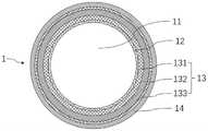
参见图2,管身1具有用于供导丝穿过的内腔11,管身1包括形成内腔11的内衬层12、设于内衬层12外侧面的中间层13、以及设于中间层13外侧面的外层14,由内衬层12形成的内腔通常比较光滑,便于导丝的移动,中间层13的力学性能较高,起到对管身1的支撑和力的传导作用,外层14与血管接触。Referring to Fig. 2, the
其中,中间层13包括第一编织层131、弹簧层132和第二编织层133,第一编织层131包裹在内衬层12外侧面,弹簧层132包裹在第一编织层131外侧面,第二编织层133包裹在弹簧层132外侧面,外层14包裹在第二编织层133的外侧面。Wherein, the
请参阅图3和图4,第二编织层133至少由第一编织丝1331和第二编织丝1332编织而成,其中,第二编织丝1332的厚度大于第一编织丝1331的厚度,第二编织丝1332沿管身1的轴向螺旋延伸,以在管身1的外表面形成向外凸起的螺旋纹路,即外层14经由第二编织丝1332的抵压形成向外凸起的螺旋纹路。3 and 4, the
本申请提供的一种微导管,中间层13通过将弹簧层132设置在第一编织层131和第二编织层133之间能够使管身1的强韧适中,弹簧层132可保证管身1在弯曲时内腔11的完整性及柔韧性,两层编织层夹持弹簧层132可避免弹簧层132在被扭转时出现迟滞现象,从而实现良好的扭矩传递效果;外层14通过第二编织丝1332的抵压形成向外凸起的螺旋纹路,从而提高管身1的扭矩传递性能,增强微导管在严重扭曲和弥漫性病变中扭转前行的能力;因此,上述方案提供的微导管,通过两层编织层夹持弹簧层132以及第二编织丝1332抵压外层14形成螺旋纹路的方式来提高扭矩传递性能,可在采用性能一般、价格便宜的弹簧层132时依然保证管身1具有较强的可扭转性能,从而降低了成本。In a microcatheter provided by the present application, the
其中,外层14通过第二编织丝1332的抵压形成向外凸起的螺旋纹路,管身凸起的螺旋纹路类似于钻头外表面的螺旋结构,这样的结构在微导管旋转时,有利于微导管向前推进,能使微导管快速穿越CTO病变。Wherein, the
应当理解的是,在微导管的中间层13中,弹簧层132的成本通常为最高的,编织层的成本要便宜很多,通过上述两层编织层的结构在保证管身1性能的情况下,可使弹簧层132采用低成本的材料,整体上降低了微导管的成本。It should be understood that, in the
其中,导管座3与管身1的近端可通过胶水进行粘连,管身1的近端外径大于远端的外径。去应力管4套设在导管座3与管身1的粘连处,以实现尺寸的过渡和避免应力集中。管身1的远端与端头2可通过热风焊接连接。内衬层12、第一编织层131、弹簧层132、第二编织层133和外层14各层之间可通过热风流变焊接为一体。管身1整体上呈由近端较硬、较粗向远端较软、较细渐变过渡。Wherein, the proximal end of the
在一些实施例中,第二编织丝1332的数量为一条或不少于两条,当第二编织丝1332的数量不少于两条时,各第二编织丝1332螺旋延伸时的旋向均相同,可避免第二编织丝1332之间交叉干涉。In some embodiments, the number of the
参见图3,本申请一种实施例示出的第二编织层133具有两条第二编织丝1332,该两条第二编织丝1332的旋向相同(均沿管身1的轴向顺时针或逆时针旋转)。优选的,两条第二编织丝1332构成对称双螺旋分布,保证管身1扭力的传递均匀。Referring to Fig. 3, the
参见图4,本申请另一种实施例示出的第二编织层133具有四条第二编织丝1332,四条第二编织丝1332的旋向相同,且两两构成一个对称双螺旋分布,保证管身1扭力的传递均匀。当然,第二编织丝1332的数量不限于两条和四条,也可以更多,但最好为偶数个,能够构成对称双螺旋分布。Referring to Fig. 4 , the
在一些实施例中,在第一编织丝1331与第二编织丝1332的交汇处,第一编织丝1331与第二编织丝1332在管身的径向上交错分布,即第一编织丝1331与第二编织丝1332相互搭接,这样工艺实现简单,使得第二编织层133顺利编织。In some embodiments, at the intersection of the
在其他一些优选的实施例中,参见图3和图4所示,在第一编织丝1331与第二编织丝1332的交汇处,第一编织丝1331穿过第二编织丝1332,即第一编织丝1331从第二编织丝1332的内部穿过,且第一编织丝1331和第二编织丝1332在交汇处的叠加厚度不大于第二编织丝1332的厚度。In some other preferred embodiments, as shown in FIG. 3 and FIG. 4 , at the intersection of the
通过在交汇处使第一编织丝1331穿过第二编织丝1332,可以加强编织结构的稳定性,使得第二编织层133不易散开,同时可以减小第二编织层133的厚度,进而减小管身1的外径。By passing the
在一些实施例中,第一编织丝1331采用金属材料制成,具体可为不锈钢,截面可为矩形,呈扁平状;第二编织丝1332采用金属材料或高分子材料制成,具体可为不锈钢或纤维聚酯材料。当第二编织丝1332采用金属材料制成时,在第一编织丝1331与第二编织丝1332的交汇处,第一编织丝1331与第二编织丝1332优选采用上下交错分布的方式进行编织。当第二编织丝1332采用高分子材料制成时,在第一编织丝1331与第二编织丝1332的交汇处,优选第一编织丝1331穿过第二编织丝1332进行编织,可通过加热熔融的方式将第一编织丝1331固定于第二编织丝1332内。In some embodiments, the
在一些实施例中,第一编织层131至少由金属材质的第三编织丝编织而成,内衬层12采用高分子材料制成。第三编织丝的结构和尺寸可与第一编织丝1331相同,截面均为矩形,可减小第一编织层131的厚度,进而减小管身1的直径。内衬层12可采用铁氟龙或其他较软树脂材料制成,保证内衬层12的柔软性。In some embodiments, the
在一些实施例中,弹簧层132为沿管身1的轴向螺旋延伸的金属丝,金属丝具体可为不锈钢材质,成本低,金属丝在厚度方向的截面可为矩形结构,呈扁平状,能够减小弹簧层132的厚度,进而减小管身1的直径。弹簧层132可以是一股或多个金属丝制成,弹簧层132可以为带锥度的弹簧层,即弹簧层132的内径可以由近端到远端逐渐减小,或者弹簧层132的厚度由近端到远端逐渐减小,这样可以在一定程度上减小管身的外径。In some embodiments, the
通过两层编织层将弹簧层132夹在中间,两层编织层对弹簧层132起到固定和限位的作用,一方面,即使外部对管身1进行持续的扭矩输入,第二编织层133也能够保护弹簧层132不会散开,提高管身1的可靠性;另一方面,在扭转管身1时,因为弹簧层132被内外两层编织层限制,能够使弹簧层132与管身1整体的变形相一致,因此可避免弹簧层132在扭转时出现迟滞现象,进而保证管身1良好的扭矩传递性能。The
在一些实施例中,外层14可由从近端到远端使用不同硬度和厚度的树脂材料对接而成,以使管身1从近端向远端呈现硬度逐级递减的效果,这样便于微导管在血管内推送。去应力管4可选用聚酯弹性体材料制成,导管座3可选用聚碳酸酯等树脂材料制成;端头2可选用含辐射透不过的钨/铋类金属粉末的树脂材料制成。In some embodiments, the
在一些实施例中,内衬层12的厚度≤0.0010英寸;第一编织层131的厚度≤0.0005英寸,第一编织层131可通过16根第三编织丝编织而成;弹簧层132的厚度≤0.0015英寸;第二编织层133中,第一编织丝1331的厚度≤0.0005英寸,第一编织丝1331的数量和第二编织的数量一共为16根,第一编织丝1331的数量和第二编织的数量一共为16根仅为本发明的一个实施例,第一编织丝1331的数量和第二编织的数量之和可以是大于16根或者小于16根,第二编织丝1332的厚度≥0.0010英寸。In some embodiments, the thickness of the
综上,本申请提供的一种微导管,通过将弹簧层132设置在第一编织层131和第二编织层133之间能够使管身1的强韧适中,不仅能保证管身1在弯曲时仍能提供圆整的内腔11供导丝通过,还增强了管身1的抗拉、抗折、推送及可扭转性能,并使弹簧层132可采用不锈钢等低成本的材料制成,进而降低微导管的成本,有利于微导管在临床介入上的推广使用。To sum up, in the microcatheter provided by the present application, by disposing the
上文中已经参考附图详细描述了本申请的方案。在上述实施例中,对各个实施例的描述都各有侧重,某个实施例中没有详细描述的部分,可以参见其他实施例的相关描述。本领域技术人员也应该知悉,说明书中所涉及的动作和模块并不一定是本申请所必需的。另外,可以理解,本申请实施例方法中的步骤可以根据实际需要进行顺序调整、合并和删减,本申请实施例装置中的模块可以根据实际需要进行合并、划分和删减。The solution of the present application has been described in detail above with reference to the accompanying drawings. In the foregoing embodiments, the descriptions of each embodiment have their own emphases, and for parts not described in detail in a certain embodiment, reference may be made to relevant descriptions of other embodiments. Those skilled in the art should also know that the actions and modules involved in the description are not necessarily required by the application. In addition, it can be understood that the steps in the method of the embodiment of the present application can be adjusted, combined and deleted in order according to actual needs, and the modules in the device of the embodiment of the present application can be combined, divided and deleted according to actual needs.
以上已经描述了本申请的各实施例,上述说明是示例性的,并非穷尽性的,并且也不限于所披露的各实施例。在不偏离所说明的各实施例的范围和精神的情况下,对于本技术领域的普通技术人员来说许多修改和变更都是显而易见的。本文中所用术语的选择,旨在最好地解释各实施例的原理、实际应用或对市场中的技术的改进,或者使本技术领域的其他普通技术人员能理解本文披露的各实施例。Having described various embodiments of the present application above, the foregoing description is exemplary, not exhaustive, and is not limited to the disclosed embodiments. Many modifications and alterations will be apparent to those of ordinary skill in the art without departing from the scope and spirit of the described embodiments. The terminology used herein is chosen to best explain the principle of each embodiment, practical application or improvement of technology in the market, or to enable other ordinary skilled in the art to understand each embodiment disclosed herein.
Claims (11)
Translated fromChinesePriority Applications (1)
| Application Number | Priority Date | Filing Date | Title |
|---|---|---|---|
| CN202210921600.6ACN115253018A (en) | 2022-08-02 | 2022-08-02 | Micro-catheter |
Applications Claiming Priority (1)
| Application Number | Priority Date | Filing Date | Title |
|---|---|---|---|
| CN202210921600.6ACN115253018A (en) | 2022-08-02 | 2022-08-02 | Micro-catheter |
Publications (1)
| Publication Number | Publication Date |
|---|---|
| CN115253018Atrue CN115253018A (en) | 2022-11-01 |
Family
ID=83746787
Family Applications (1)
| Application Number | Title | Priority Date | Filing Date |
|---|---|---|---|
| CN202210921600.6APendingCN115253018A (en) | 2022-08-02 | 2022-08-02 | Micro-catheter |
Country Status (1)
| Country | Link |
|---|---|
| CN (1) | CN115253018A (en) |
Cited By (3)
| Publication number | Priority date | Publication date | Assignee | Title |
|---|---|---|---|---|
| CN115970127A (en)* | 2022-12-30 | 2023-04-18 | 江苏赛腾医疗科技有限公司 | Medical cannula |
| CN116058912A (en)* | 2022-12-02 | 2023-05-05 | 上海励楷科技有限公司 | braided catheter |
| WO2024193585A1 (en)* | 2023-03-20 | 2024-09-26 | Covidien Lp | Neurovascular access catheters and methods of use |
Citations (7)
| Publication number | Priority date | Publication date | Assignee | Title |
|---|---|---|---|---|
| US5403292A (en)* | 1994-05-18 | 1995-04-04 | Schneider (Usa) Inc. | Thin wall catheter having enhanced torqueability characteristics |
| KR200254123Y1 (en)* | 2001-08-17 | 2001-12-01 | 김석 | resisting pressure flat a hose |
| US6554820B1 (en)* | 2000-03-08 | 2003-04-29 | Scimed Life Systems, Inc. | Composite flexible tube for medical applications |
| CN105473080A (en)* | 2013-08-20 | 2016-04-06 | 波士顿科学国际有限公司 | Braided hemostatic shaft for enhanced torsional response |
| US20170072165A1 (en)* | 2015-09-11 | 2017-03-16 | Cathera, Inc. | Catheter shaft and associated devices, systems, and methods |
| CN108514677A (en)* | 2018-04-28 | 2018-09-11 | 业聚医疗器械(深圳)有限公司 | A kind of microtubular |
| CN215537612U (en)* | 2020-12-22 | 2022-01-18 | 深圳北芯生命科技股份有限公司 | Micro-catheter |
- 2022
- 2022-08-02CNCN202210921600.6Apatent/CN115253018A/enactivePending
Patent Citations (8)
| Publication number | Priority date | Publication date | Assignee | Title |
|---|---|---|---|---|
| US5403292A (en)* | 1994-05-18 | 1995-04-04 | Schneider (Usa) Inc. | Thin wall catheter having enhanced torqueability characteristics |
| US6554820B1 (en)* | 2000-03-08 | 2003-04-29 | Scimed Life Systems, Inc. | Composite flexible tube for medical applications |
| KR200254123Y1 (en)* | 2001-08-17 | 2001-12-01 | 김석 | resisting pressure flat a hose |
| CN105473080A (en)* | 2013-08-20 | 2016-04-06 | 波士顿科学国际有限公司 | Braided hemostatic shaft for enhanced torsional response |
| US20170072165A1 (en)* | 2015-09-11 | 2017-03-16 | Cathera, Inc. | Catheter shaft and associated devices, systems, and methods |
| US20220016391A1 (en)* | 2015-09-11 | 2022-01-20 | Covidien Lp | Catheter shaft and associated devices, systems, and methods |
| CN108514677A (en)* | 2018-04-28 | 2018-09-11 | 业聚医疗器械(深圳)有限公司 | A kind of microtubular |
| CN215537612U (en)* | 2020-12-22 | 2022-01-18 | 深圳北芯生命科技股份有限公司 | Micro-catheter |
Cited By (4)
| Publication number | Priority date | Publication date | Assignee | Title |
|---|---|---|---|---|
| CN116058912A (en)* | 2022-12-02 | 2023-05-05 | 上海励楷科技有限公司 | braided catheter |
| CN115970127A (en)* | 2022-12-30 | 2023-04-18 | 江苏赛腾医疗科技有限公司 | Medical cannula |
| WO2024139753A1 (en)* | 2022-12-30 | 2024-07-04 | 江苏赛腾医疗科技有限公司 | Medical cannula |
| WO2024193585A1 (en)* | 2023-03-20 | 2024-09-26 | Covidien Lp | Neurovascular access catheters and methods of use |
Similar Documents
| Publication | Publication Date | Title |
|---|---|---|
| CN115253018A (en) | Micro-catheter | |
| US5984907A (en) | Transition sleeve assembly for catheters | |
| CN211560260U (en) | Sectional type adjustable bending micro-catheter | |
| US7695451B2 (en) | Steerable device for introducing diagnostic and therapeutic apparatus into the body | |
| JP4889062B2 (en) | Guide wire | |
| US20080188800A1 (en) | Steerable Device For Introducing Diagnostic And Therapeutic Apparatus Into The Body | |
| CN108742835A (en) | Catheters with improved ring retraction and greater retraction displacement | |
| KR20150037905A (en) | Electrode catheter and method for manufacturing same | |
| EP0844845A2 (en) | Electrode catheter | |
| WO1993008869A1 (en) | Catheter with electrode tip having asymmetric configurations | |
| CN211705584U (en) | Micro catheter with spiral lines | |
| CN111672010A (en) | microcatheter | |
| JP6396026B2 (en) | Catheter having a flat beam deflection tip with a fiber retracting member | |
| JPWO2008056625A1 (en) | Medical catheter tube | |
| CN110193132A (en) | A kind of foley's tube | |
| CN118078384A (en) | A scored balloon catheter | |
| CN211675820U (en) | Screw type micro-catheter | |
| WO2021238018A1 (en) | Microcatheter having double cavities | |
| CN204147116U (en) | A kind of guiding catheter | |
| CN116688316A (en) | microcatheter | |
| CN218010599U (en) | Micro-catheter | |
| CN219048685U (en) | Spring ring for interventional embolism and system thereof | |
| WO2024098930A1 (en) | Microcatheter | |
| WO2020031409A1 (en) | Guide wire | |
| CN115317768A (en) | Double-cavity micro catheter |
Legal Events
| Date | Code | Title | Description |
|---|---|---|---|
| PB01 | Publication | ||
| PB01 | Publication | ||
| SE01 | Entry into force of request for substantive examination | ||
| SE01 | Entry into force of request for substantive examination | ||
| RJ01 | Rejection of invention patent application after publication | Application publication date:20221101 | |
| RJ01 | Rejection of invention patent application after publication |