Movatterモバイル変換


[0]ホーム

URL:


CN115252264A - Apparatus and method for receiving excreted urine - Google Patents

Apparatus and method for receiving excreted urine
Download PDF

Info

Publication number
CN115252264A
CN115252264ACN202210964260.5ACN202210964260ACN115252264ACN 115252264 ACN115252264 ACN 115252264ACN 202210964260 ACN202210964260 ACN 202210964260ACN 115252264 ACN115252264 ACN 115252264A
Authority
CN
China
Prior art keywords
fluid
tube
reservoir
region
permeable
Prior art date
Legal status (The legal status is an assumption and is not a legal conclusion. Google has not performed a legal analysis and makes no representation as to the accuracy of the status listed.)
Pending
Application number
CN202210964260.5A
Other languages
Chinese (zh)
Inventor
罗伯特·A·桑切斯
卡米尔·R·牛顿
约瑟夫·M·福汉德
雷蒙德·J·牛顿
Current Assignee (The listed assignees may be inaccurate. Google has not performed a legal analysis and makes no representation or warranty as to the accuracy of the list.)
PureWick Corp
Original Assignee
PureWick Corp
Priority date (The priority date is an assumption and is not a legal conclusion. Google has not performed a legal analysis and makes no representation as to the accuracy of the date listed.)
Filing date
Publication date
Family has litigation
First worldwide family litigation filedlitigationCriticalhttps://patents.darts-ip.com/?family=60477975&utm_source=google_patent&utm_medium=platform_link&utm_campaign=public_patent_search&patent=CN115252264(A)"Global patent litigation dataset” by Darts-ip is licensed under a Creative Commons Attribution 4.0 International License.
Priority claimed from US15/171,968external-prioritypatent/US10952889B2/en
Priority claimed from US15/260,103external-prioritypatent/US10390989B2/en
Priority claimed from US15/611,587external-prioritypatent/US10226376B2/en
Application filed by PureWick CorpfiledCriticalPureWick Corp
Publication of CN115252264ApublicationCriticalpatent/CN115252264A/en
Pendinglegal-statusCriticalCurrent

Links

Images

Classifications

Landscapes

Abstract

A system adapted to collect and transport urine away from a human or animal body may include an assembly having a fluid impermeable housing with a fluid reservoir at a first end, a fluid outlet at a second end, and a longitudinally extending fluid impermeable layer connected with the fluid reservoir and the fluid outlet and defining a longitudinal elongate opening therebetween. The assembly may also include a fluid permeable support disposed within the housing, a portion of the support extending across the elongate opening, and a fluid permeable membrane disposed on the support and covering at least a portion of the support extending across the elongate opening such that the membrane is supported on the support and disposed across the elongate opening. The assembly also includes a tube having a first end disposed in the reservoir, and a second fluid discharge end.

Description

Translated fromChinese
用于接收排出的尿液的装置和方法Device and method for receiving voided urine

相关申请的交叉引用Cross References to Related Applications

本申请是于2017年6月1日提交的标题为“Apparatus and Methods forReceiving Discharged Urine”、申请号为15/611,587的美国专利申请的继续申请,并要求其优先权和权益。本申请还要求以下专利申请的优先权和权益:于2016年10月31日提交的标题为“Apparatus and Methods for Receiving Discharged Urine”、申请号为62/414,963的美国专利申请;于2017年4月14日提交的标题为“Apparatus and Methods forReceiving Discharged Urine”、申请号为62/485,578的美国专利申请;于2016年9月8日提交的标题为“Apparatus and Methods for Receiving Discharged Urine”、申请号为15/260,103的美国专利申请;于2016年8月29日提交的标题为“Apparatus and Methods forReceiving Discharged Urine”、PCT专利申请号为PCT/US2016/049274的国际专利申请;和于2016年6月2日提交的标题为“Using Wicking Material To Collect Liquid ForTransport”、申请号为15/171,968的美国专利申请。所有上述申请的公开内容通过引用整体并入本文。This application is a continuation of, and claims priority and benefit from, U.S. Patent Application No. 15/611,587, filed June 1, 2017, entitled "Apparatus and Methods for Receiving Discharged Urine." This application also claims priority to and benefit from: U.S. Patent Application No. 62/414,963, filed October 31, 2016, entitled "Apparatus and Methods for Receiving Discharged Urine"; U.S. Patent Application No. 62/485,578 filed on the 14th, entitled "Apparatus and Methods for Receiving Discharged Urine"; 15/260,103; International Patent Application No. PCT/US2016/049274, filed August 29, 2016, entitled "Apparatus and Methods for Receiving Discharged Urine"; and US Patent Application No. 15/171,968, entitled "Using Wicking Material To Collect Liquid For Transport", filed on . The disclosures of all of the aforementioned applications are incorporated herein by reference in their entirety.

技术领域technical field

本公开主要涉及用于从人或动物的身体收集和运走尿液的系统、装置和方法。The present disclosure generally relates to systems, devices and methods for collecting and transporting urine from the body of a human or animal.

背景技术Background technique

本文所述的实施例主要涉及从人或动物的身体收集和运走尿液。在许多情况下,人或动物的行动能力可能有限或受损,使得通常的排尿过程具有挑战性或不可能。例如,人可能经历或患有损害行动能力的残疾。人可能会处在限制移动条件下,例如飞行员、驾驶员和处在危险区域的工人所经历的那些条件。此外,有时为了监测目的或临床试验需要收集尿液。The embodiments described herein are primarily concerned with collecting and transporting urine from the body of a human or animal. In many cases, the human or animal's mobility may be limited or impaired, making the usual process of urination challenging or impossible. For example, a person may experience or have a disability that impairs mobility. People may be subject to restricted movement conditions such as those experienced by pilots, drivers and workers in hazardous areas. In addition, urine collection is sometimes required for monitoring purposes or clinical trials.

导尿管,如Foley导尿管,可用于处理其中一些情况,如尿失禁。然而,不幸的是,导尿管可能使人不舒服,痛苦,并可能导致并发症,如感染。此外,有时会使用便盆,这是卧床不起的病人(如疗养院中的那些病人)的如厕容器。然而,便盆可能易于产生不适、溢出和其他卫生问题。A urinary catheter, such as a Foley catheter, may be used to manage some of these conditions, such as urinary incontinence. Unfortunately, however, urinary catheters can be uncomfortable, painful, and can lead to complications such as infection. Additionally, bedpans are sometimes used, which are toilet receptacles for bedridden patients, such as those in nursing homes. Bedpans, however, can be prone to discomfort, spillage, and other hygiene problems.

因此,亟需一种能够舒适地从人或动物收集尿液并且对用户和/或周围区域的污染最小的设备。Accordingly, there is a need for a device that can comfortably collect urine from a human or animal with minimal contamination to the user and/or the surrounding area.

发明内容Contents of the invention

本发明公开了一种适于从人或动物的身体收集和运走尿液的系统。所公开的系统包括组件,该组件可以包括流体不可渗透壳体,该流体不可渗透壳体具有位于第一端处的流体贮存器,位于第二端处的流体出口,以及纵向延伸的流体不可渗透层,该流体不可渗透层连接至流体贮存器和流体出口,并限定了位于流体贮存器和流体出口之间的纵向长形开口。该组件还可包括:设置在壳体内的流体可渗透支撑件,其中流体可渗透支撑件的一部分横跨长形开口延伸;以及流体可渗透膜,该流体可渗透膜设置在支撑件上并且至少覆盖支撑件的横跨长形开口延伸的部分,使得该膜被支撑在支撑件上并横跨长形开口设置。该组件还可包括管,所述管具有设置在贮存器内的第一端,且所述管至少在横跨长形开口设置的支撑件的所述部分和膜的所述部分的后方延伸,并且穿过流体出口延伸至第二流体排出端。该组件可被配置成设置有与用户的尿道口邻近的所述开口,以通过使从尿道口排出的尿液流过流体不可渗透层的开口、膜、支撑件、并流入贮存器来接收所述尿液,并令所接收的尿液流过所述管并流出该管的流体排出端而从贮存器中排出。The present invention discloses a system suitable for collecting and transporting urine from a human or animal body. The disclosed system includes an assembly that may include a fluid impermeable housing having a fluid reservoir at a first end, a fluid outlet at a second end, and a longitudinally extending fluid impermeable housing. A layer, the fluid impermeable layer is connected to the fluid reservoir and the fluid outlet, and defines a longitudinally elongated opening between the fluid reservoir and the fluid outlet. The assembly may also include: a fluid permeable support disposed within the housing, wherein a portion of the fluid permeable support extends across the elongate opening; and a fluid permeable membrane disposed on the support and at least The portion of the support extending across the elongated opening is covered such that the membrane is supported on the support and disposed across the elongated opening. The assembly may also include a tube having a first end disposed within the reservoir, the tube extending behind at least the portion of the support disposed across the elongated opening and the portion of the membrane, And extend through the fluid outlet to the second fluid discharge port. The assembly may be configured to be provided with said opening adjacent to the user's urethral opening to receive the urine by allowing urine expelled from the urethral opening to flow through the opening of the fluid-impermeable layer, the membrane, the support, and into the reservoir. The urine is discharged from the reservoir by causing the received urine to flow through the tube and out the fluid discharge end of the tube.

附图说明Description of drawings

图1是根据一个实施例的系统的示意性框图。Figure 1 is a schematic block diagram of a system according to one embodiment.

图2是根据一个实施例的组件的透视图,其中组件的一部分被剖开展示。Figure 2 is a perspective view of an assembly according to one embodiment, with a portion of the assembly shown cut away.

图3是包括可渗透膜的图2的组件的透视图。Figure 3 is a perspective view of the assembly of Figure 2 including a permeable membrane.

图4是图2的组件作为系统一部分的示意图。FIG. 4 is a schematic diagram of the components of FIG. 2 as part of a system.

图5是根据一个实施例的系统的示意图。Figure 5 is a schematic diagram of a system according to one embodiment.

图6A是根据一个实施例的组件的前视图。Figure 6A is a front view of an assembly according to one embodiment.

图6B是根据一个实施例的组件的前视图。Figure 6B is a front view of an assembly according to one embodiment.

图6C是根据一个实施例的组件的前视图。Figure 6C is a front view of an assembly according to one embodiment.

图7是根据一个实施例的组件的透视图,其中组件的一部分被剖开展示。Figure 7 is a perspective view of an assembly according to one embodiment, with a portion of the assembly shown cut away.

图8是根据一个实施例的组件的透视图。Figure 8 is a perspective view of an assembly according to one embodiment.

图9是根据一个实施例的、包括可渗透膜的图8的组件的透视图。Figure 9 is a perspective view of the assembly of Figure 8 including a permeable membrane, according to one embodiment.

图10是根据一个实施例的可渗透支撑件的第一端的透视图。Figure 10 is a perspective view of a first end of a permeable support according to one embodiment.

图11是根据一个实施例的可渗透支撑件的第二端的透视图。Figure 11 is a perspective view of a second end of a permeable support according to one embodiment.

图12是根据一个实施例的第一端盖的透视图。Figure 12 is a perspective view of a first end cap according to one embodiment.

图13是根据一个实施例的第二端盖的透视图。Figure 13 is a perspective view of a second end cap according to one embodiment.

图14是根据一个实施例的尿液测试条在管线的一部分中的示意图。Figure 14 is a schematic illustration of a urine test strip in a portion of a line, according to one embodiment.

图15是根据一个实施例的组件的透视图。Figure 15 is a perspective view of an assembly according to one embodiment.

图16是根据一个实施例的可渗透支撑件的透视图。Figure 16 is a perspective view of a permeable support according to one embodiment.

图17为图16的可渗透支撑件沿线17-17剖切的横截面视图。17 is a cross-sectional view of the permeable support of FIG. 16 taken along line 17-17.

图18是根据一个实施例的、包括图16的可渗透支撑件的组件的侧视图。Figure 18 is a side view of an assembly including the permeable support of Figure 16, according to one embodiment.

图19是根据一个实施例的可渗透支撑件的透视图。Figure 19 is a perspective view of a permeable support according to one embodiment.

图20为图19的可渗透支撑件沿线20-20剖切的横截面视图。20 is a cross-sectional view of the permeable support of FIG. 19 taken along line 20-20.

图21是根据一个实施例的、包括图19的可渗透支撑件的组件的侧视图。Figure 21 is a side view of an assembly including the permeable support of Figure 19, according to one embodiment.

图22-24分别是根据一个实施例的组件的前视图、后视图和侧视图。22-24 are front, rear and side views, respectively, of an assembly according to one embodiment.

图25是包括不可渗透背衬的图22的组件的侧视图。Figure 25 is a side view of the assembly of Figure 22 including an impermeable backing.

图26是包括可渗透膜的图22的组件的前视图。Figure 26 is a front view of the assembly of Figure 22 including a permeable membrane.

图27是根据一个实施例的不可渗透壳体的俯视图;Figure 27 is a top view of an impermeable shell according to one embodiment;

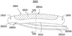
图28为图27的不可渗透壳体沿线28-28剖切的横截面侧视图。28 is a cross-sectional side view of the impermeable shell of FIG. 27 taken along line 28-28.

图29是根据一个实施例的、处于第一配置中的可渗透支撑件的俯视图。Figure 29 is a top view of a permeable support in a first configuration, according to one embodiment.

图30是处于第二配置中的图29的可渗透支撑件的透视图。30 is a perspective view of the permeable support of FIG. 29 in a second configuration.

图31是具有可渗透膜的图29的可渗透支撑件的透视图。31 is a perspective view of the permeable support of FIG. 29 with a permeable membrane.

图32是根据一个实施例的组件的横截面侧视图。Figure 32 is a cross-sectional side view of an assembly according to one embodiment.

图33为与女性身体接合的图32的组件的横截面侧视图。Figure 33 is a cross-sectional side view of the assembly of Figure 32 engaged with a female body.

图34是根据一个实施例的组件的爆炸图。Figure 34 is an exploded view of an assembly according to one embodiment.

图35是在组装配置中的图34的组件的侧视图。35 is a side view of the assembly of FIG. 34 in an assembled configuration.

图36是根据一个实施例的组件的一部分的爆炸图。Figure 36 is an exploded view of a portion of an assembly according to one embodiment.

图37是图36的组件的局部组装配置的俯视图。37 is a top view of a partially assembled configuration of the assembly of FIG. 36 .

图38是在组装配置中的图36的组件的侧视图。38 is a side view of the assembly of FIG. 36 in an assembled configuration.

图39是根据一个实施例的、使用组件从用户收集尿液的方法的流程图。Figure 39 is a flowchart of a method of collecting urine from a user using an assembly, according to one embodiment.

图40是根据一个实施例的包括真空释放开口的不可渗透壳体的后视图。Figure 40 is a rear view of an impermeable shell including a vacuum relief opening, according to one embodiment.

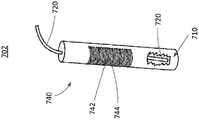
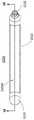
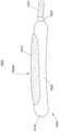
图41是根据一个实施例的具有预弯曲形状的管的示意图。Figure 41 is a schematic illustration of a tube having a pre-bent shape, according to one embodiment.

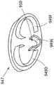
图42是根据一个实施例的形状保持元件的示意图。Figure 42 is a schematic illustration of a shape retaining element according to one embodiment.

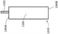
图43是根据一个实施例的具有倾斜进气端的管的示意图。Figure 43 is a schematic illustration of a tube with a sloped inlet end, according to one embodiment.

图44A是根据一个实施例的具有预弯曲形状的不可渗透壳体的示意图,该不可渗透壳体包括通道和开口以移除从用户收集的尿液。44A is a schematic illustration of an impermeable shell having a pre-curved shape including channels and openings to remove urine collected from a user, according to one embodiment.

图44B是将图44A中的壳体沿线44B-44B剖切的示意性横截面视图。44B is a schematic cross-sectional view of the housing of FIG. 44A taken alongline 44B-44B.

图44C是将图44A中的壳体沿线44C-44C剖切的横截面视图。Figure 44C is a cross-sectional view of the housing of Figure 44A taken alongline 44C-44C.

图44D是图44A中所示的壳体中的不可渗透背衬的示意性横截面仰视图,其展示了来自贮存器的开口。Figure 44D is a schematic cross-sectional bottom view of the impermeable backing in the housing shown in Figure 44A showing the opening from the reservoir.

图45是根据一个实施例的壳体的示意图,该壳体具有管和来自组件的贮存器的开口。Figure 45 is a schematic illustration of a housing with a tube and an opening from the reservoir of the assembly, according to one embodiment.

图46和图47是根据一个实施例的组件的示意性侧视图和爆炸图,该组件具有壳体和多孔支撑材料。46 and 47 are schematic side and exploded views of an assembly having a housing and a porous support material according to one embodiment.

图48是用作图46和图47的实施例的可渗透支撑件的材料片的俯视图。48 is a top view of a sheet of material used as a permeable support for the embodiment of FIGS. 46 and 47 .

图49A是根据一个实施例的组件的示意性横截面图。Figure 49A is a schematic cross-sectional view of an assembly according to one embodiment.

图49B是图49A的组件的不可渗透壳体的示意性横截面图。Figure 49B is a schematic cross-sectional view of the impermeable shell of the assembly of Figure 49A.

图49C是图49B的不可渗透壳体沿线49C-49C剖切的示意性横截面图。Figure 49C is a schematic cross-sectional view of the impermeable shell of Figure 49B taken alongline 49C-49C.

图50A是根据一个实施例的、具有多于一个出口管的组件的示意图。Figure 50A is a schematic illustration of an assembly with more than one outlet tube, according to one embodiment.

图50B是图50A的组件沿线50B-50B剖切的横截面视图。Figure 50B is a cross-sectional view of the assembly of Figure 50A taken alongline 50B-50B.

图51是图50A的组件的浅角度透视图。Figure 51 is a shallow perspective view of the assembly of Figure 50A.

具体实施方式Detailed ways

本发明公开了一种适于从人或动物的身体收集和运走尿液的系统。所公开的系统包括组件,该组件可以包括流体不可渗透壳体,该流体不可渗透壳体具有在第一端的流体贮存器,在第二端的流体出口,以及纵向延伸的流体不可渗透层,该流体不可渗透层与流体贮存器和流体出口连接,并限定了位于流体贮存器和流体出口之间的纵向长形开口。该组件还可包括:设置在壳体内的流体可渗透支撑件,该流体可渗透支撑件具有横跨长形开口延伸的部分;以及流体可渗透膜,该流体可渗透膜设置在支撑件上并至少覆盖支撑件的横跨长形开口延伸的部分,使得该膜被支撑在支撑件上并横跨长形开口设置。该组件还可包括管,所述管具有设置在贮存器内的第一端,并且该管至少在横跨长形开口设置的支撑件的部分和膜的部分的后方延伸,并且穿过流体出口延伸至第二流体排出端。该组件可被配置成设置有与用户的尿道口邻近的所述开口,以通过使从尿道口排出的尿液流过流体不可渗透层的开口、膜、支撑件、并流入贮存器来接收所述尿液,并令所接收的尿液流过所述管并流出该管的流体排出端而从贮存器中排出。The present invention discloses a system suitable for collecting and transporting urine from a human or animal body. The disclosed system includes an assembly that may include a fluid impermeable housing having a fluid reservoir at a first end, a fluid outlet at a second end, and a longitudinally extending fluid impermeable layer that A fluid impermeable layer is connected to the fluid reservoir and the fluid outlet and defines a longitudinally elongated opening between the fluid reservoir and the fluid outlet. The assembly may also include: a fluid permeable support disposed within the housing, the fluid permeable support having a portion extending across the elongate opening; and a fluid permeable membrane disposed on the support and At least the portion of the support extending across the elongated opening is covered such that the membrane is supported on the support and disposed across the elongated opening. The assembly may also include a tube having a first end disposed within the reservoir and extending behind at least a portion of the support and a portion of the membrane disposed across the elongated opening and through the fluid outlet Extends to the second fluid discharge port. The assembly may be configured to be provided with said opening adjacent to the user's urethral opening to receive the urine by allowing urine expelled from the urethral opening to flow through the opening of the fluid-impermeable layer, the membrane, the support, and into the reservoir. The urine is discharged from the reservoir by causing the received urine to flow through the tube and out the fluid discharge end of the tube.

在一些实施例中,一种方法包括设置一尿液收集装置、使其与女性用户的尿道口为操作关系。该尿液收集装置可包括流体不可渗透壳体,该流体不可渗透壳体具有在第一端的流体贮存器,在第二端的流体出口,以及纵向延伸的流体不可渗透层,该流体不可渗透层与流体贮存器和流体出口连接,并限定了位于流体贮存器和流体出口之间的纵向长形开口。该尿液收集装置还可包括:设置在壳体内的流体可渗透支撑件,该流体可渗透支撑件具有横跨长形开口延伸的部分;流体可渗透膜,该流体可渗透膜设置在支撑件上并至少覆盖支撑件横跨长形开口延伸的部分,使得该膜被支撑在支撑件上并横跨长形开口设置;以及管,所述管具有设置在贮存器内的第一端,该管至少在横跨长形开口设置的支撑件的部分以及膜的部分的后方延伸,并且穿过流体出口延伸至第二流体排出端。操作关系可包括开口与尿道口邻近。该方法还可包括允许从尿道口排出的尿液流过流体不可渗透层的开口、膜、支撑件、并流入贮存器而被接收;并允许所接收的尿液通过流过所述管并流出管的流体排出端而从所述贮存器中排出。In some embodiments, a method includes positioning a urine collection device in operative relationship with a urethral opening of a female user. The urine collection device may include a fluid impermeable housing having a fluid reservoir at a first end, a fluid outlet at a second end, and a longitudinally extending fluid impermeable layer, the fluid impermeable layer Connected to the fluid reservoir and the fluid outlet, and defining a longitudinally elongated opening between the fluid reservoir and the fluid outlet. The urine collection device may also include: a fluid permeable support disposed within the housing, the fluid permeable support having a portion extending across the elongate opening; a fluid permeable membrane disposed on the support and covering at least the portion of the support that extends across the elongated opening, such that the membrane is supported on the support and disposed across the elongated opening; and a tube having a first end disposed within the reservoir, the The tube extends behind at least the portion of the support disposed across the elongated opening and behind the portion of the membrane and through the fluid outlet to the second fluid discharge end. The operative relationship may include the opening being adjacent to the meatus of the urethra. The method may also include allowing urine expelled from the urethral opening to flow through the opening of the fluid-impermeable layer, the membrane, the support, and into the reservoir to be received; and allowing the received urine to flow through the tube and out The fluid discharge end of the tube is drained from the reservoir.

在一些实施例中,装置包括设置在流体可渗透膜和流体贮存器之间的流体可渗透支撑件,以及流体出口。该装置可配置成设置有与用户的尿道口邻近的所述流体可渗透膜的一部分,以通过使从尿道口排出的尿液流过流体可渗透膜、流体可渗透支撑件、并流入贮存器来接收所述尿液,并令所接收的尿液通过所述出口而从贮存器中排出。In some embodiments, the device includes a fluid permeable support disposed between the fluid permeable membrane and the fluid reservoir, and a fluid outlet. The device may be configured to provide a portion of the fluid permeable membrane adjacent to the user's urethral opening to allow urine expelled from the urethral opening to flow through the fluid permeable membrane, the fluid permeable support, and into the reservoir. to receive the urine and allow the received urine to be expelled from the reservoir through the outlet.

除非上下文另有明确规定,否则如本说明书中所使用的单数形式“一”,“一个”和“该”均包括复数指代对象。因此,例如,术语“一构件”旨在表示单个构件或多个构件的组合,“一材料”旨在表示一种或多种材料,或其组合。As used in this specification, the singular forms "a", "an" and "the" include plural referents unless the context clearly requires otherwise. Thus, for example, the term "a member" is intended to mean a single member or a combination of members, "a material" is intended to mean one or more materials, or a combination thereof.

本文所述的实施例可由一种或多种生物相容性材料形成或构建。合适的生物相容性材料的示例包括金属、陶瓷或聚合物。合适的金属的示例包括医药级不锈钢、金、钛、镍、铁、铂、锡、铬、铜和/或其合金。聚合物的示例包括尼龙,聚酯,聚碳酸酯,聚丙烯酸酯,乙烯-乙酸乙烯酯和其它酰基取代的乙酸纤维素的聚合物,不可降解的聚氨酯,聚苯乙烯,聚氯乙烯,聚氟乙烯,聚(乙烯基咪唑),氯磺酸酯聚烯烃,聚环氧乙烷,聚对苯二甲酸乙二醇酯(PET),聚四氟乙烯(PTFE)和/或其共混物和共聚物。Embodiments described herein may be formed or constructed from one or more biocompatible materials. Examples of suitable biocompatible materials include metals, ceramics or polymers. Examples of suitable metals include medical grade stainless steel, gold, titanium, nickel, iron, platinum, tin, chromium, copper, and/or alloys thereof. Examples of polymers include nylon, polyester, polycarbonate, polyacrylate, ethylene-vinyl acetate and other acyl-substituted cellulose acetate polymers, non-degradable polyurethane, polystyrene, polyvinyl chloride, polyfluoro Ethylene, poly(vinylimidazole), chlorosulfonate polyolefin, polyethylene oxide, polyethylene terephthalate (PET), polytetrafluoroethylene (PTFE) and/or blends thereof and copolymer.

图1是系统100的示意性框图。系统100包括组件102。组件102包括贮存器110、可渗透支撑件140和可渗透膜130。组件102还包括与贮存器110流体连通的出口120。组件102可布置成使得流体可流过可渗透膜130,流过可渗透支撑件140,进入贮存器110,并流出出口120。在一些实施方式中,组件102还可包括不可渗透层150,用于将流体引向贮存器110,并减少和/或防止流体离开组件102,除非通过出口120离开。在一些实施方式中,系统100可包括排出线122。排出线122可与外部接收器160流体连接。外部接收器160可通过真空线124与真空源170流体连通。排出线122和真空线124都可包括柔性管件,例如柔性塑料管件。FIG. 1 is a schematic block diagram of asystem 100 .System 100 includescomponent 102 .Assembly 102 includes reservoir 110 , permeable support 140 and permeable membrane 130 .Assembly 102 also includes anoutlet 120 in fluid communication with reservoir 110 .Assembly 102 may be arranged such that fluid may flow through permeable membrane 130 , through permeable support 140 , into reservoir 110 , and out ofoutlet 120 . In some embodiments,assembly 102 may also include animpermeable layer 150 for directing fluid toward reservoir 110 and reducing and/or preventing fluid from exitingassembly 102 except throughoutlet 120 . In some embodiments, thesystem 100 can include a drain line 122 . Drain line 122 may be fluidly connected toexternal receiver 160 .External receiver 160 may be in fluid communication with vacuum source 170 via vacuum line 124 . Both exhaust line 122 and vacuum line 124 may comprise flexible tubing, such as flexible plastic tubing.

可渗透膜130可由对诸如尿液的液体具有可渗透性质的材料形成。可渗透性质可以是芯吸,毛细管作用,扩散或其他类似的性质或过程,并且在本文中称为“(可)渗透”和/或“芯吸”。可渗透膜130可具有高吸收率和高渗透率,使得尿液可被可渗透膜130快速吸收和/或通过可渗透膜130快速运输。在一些实施方式中,可渗透膜130可以是罗纹针织织物。在一些实施方式中,可渗透膜130可包括和/或具有纱布、毛毡、绒布、厚纸巾和/或纸巾的吸湿特性。在一些实施方式中,可渗透膜130可以是柔软的和/或最小磨蚀性的,使得可渗透膜130不会刺激用户的皮肤。可渗透膜130可被配置成将流体从尿道口和/或用户的皮肤上芯吸吸走,使得用户皮肤的湿气减轻并防止感染。此外,可渗透膜130的芯吸性质可帮助防止尿液泄漏或溢出组件流到例如床上。在一些实施方式中,可渗透膜130可由涂有热塑性水基粘结剂系统的细旦聚酯纤维形成。韦伯方向的拉力可使用Instron测试方法测量,例如,约为45磅/英寸2。每一可渗透膜的重量可使用Mettle Gram Scale测量,例如,约为12克。每十层可渗透膜的厚度可使用Gustin-Bacon/Measure-Matic测量,例如,约为2.5”。The permeable membrane 130 may be formed of a material having a permeable property to liquid such as urine. The permeable property may be wicking, capillary action, diffusion or other similar property or process, and is referred to herein as "(permeable)" and/or "wicking". The permeable membrane 130 may have a high absorbency and high permeability such that urine may be rapidly absorbed by the permeable membrane 130 and/or rapidly transported through the permeable membrane 130 . In some embodiments, permeable membrane 130 may be a rib knit fabric. In some embodiments, the permeable membrane 130 may include and/or have the absorbent properties of gauze, felt, fleece, cardboard, and/or paper towels. In some embodiments, permeable membrane 130 may be soft and/or minimally abrasive such that permeable membrane 130 does not irritate the user's skin. The permeable membrane 130 may be configured to wick fluid away from the urethral opening and/or the user's skin so that the user's skin is relieved of moisture and infection is prevented. Additionally, the wicking properties of the permeable membrane 130 can help prevent urine from leaking or spilling over the assembly onto, for example, the bed. In some embodiments, permeable membrane 130 may be formed from fine polyester fibers coated with a thermoplastic water-based binder system. Weber-direction pull can be measured using the Instron test method, for example, at about 45 lbs/in2 . The weight of each permeable membrane can be measured using the Mettle Gram Scale, eg, about 12 grams. The thickness of every ten layers of the permeable membrane can be measured using a Gustin-Bacon/Measure-Matic, eg, about 2.5".

可渗透支撑件140可相对于可渗透膜130定位,使得可渗透支撑件140将可渗透膜130维持在特定形状,并允许诸如尿液的流体流过可渗透膜130、流过可渗透支撑件140、并进入贮存器110。在一些实施方式中,可渗透支撑件140可配置为维持可渗透膜130抵靠或靠近用户的尿道口。例如,可渗透支撑件140可包括具有弯曲形状的部分,该部分与可渗透膜130接触使得可渗透膜130也是弯曲的,从而产生用于与用户的尿道口和/或尿道口附近的身体区域接合的舒适且牢固的界面。在一些实施方式中,可渗透支撑件140可用硬质塑料制成。在一些实施方式中,可渗透支撑件140可具有任何合适的形状,并由任何合适的材料制成。例如,可渗透支撑件140可以是柔性的。此外,可渗透支撑件140可由以下材料制成:铝,塑料与铝的复合材料,一些其他金属,和/或塑料与另一种金属的复合材料。在一些实施方式中,可渗透支撑件140可由天然材料形成,例如植物纤维(例如,由

Figure BDA0003794141120000071
制造的GreenerClean)。天然材料可包括允许流体流过天然材料的开口。在一些实施例中,可渗透支撑件140可以是圆筒形的,并可限定有内腔。在一些实施例中,可渗透支撑件140可由穿孔涂布纸形成,例如管状蜡纸。The permeable support 140 can be positioned relative to the permeable membrane 130 such that the permeable support 140 maintains the permeable membrane 130 in a particular shape and allows fluid, such as urine, to flow through the permeable membrane 130, through the permeable support 140, and enter the reservoir 110. In some embodiments, the permeable support 140 can be configured to maintain the permeable membrane 130 against or near the user's urethral opening. For example, the permeable support 140 may include a portion having a curved shape that contacts the permeable membrane 130 such that the permeable membrane 130 is also curved, thereby creating an opening for contact with the user's urethral opening and/or the body area near the urethral opening. Comfortable and secure interface for joining. In some embodiments, permeable support 140 may be made of rigid plastic. In some embodiments, permeable support 140 can have any suitable shape and be made of any suitable material. For example, permeable support 140 may be flexible. Additionally, permeable support 140 may be made of aluminum, a composite of plastic and aluminum, some other metal, and/or a composite of plastic and another metal. In some embodiments, permeable support 140 may be formed from natural materials, such as plant fibers (e.g., from
Figure BDA0003794141120000071
Manufactured by GreenerClean). The natural material may include openings that allow fluid to flow through the natural material. In some embodiments, permeable support 140 can be cylindrical and can define a lumen. In some embodiments, permeable support 140 may be formed from perforated coated paper, such as tubular waxed paper.

可渗透支撑件140可限定一个或多个开口(例如,开口阵列)以允许流体从可渗透膜130流到贮存器110。在一些实施例中,可渗透支撑件140可形成为具有一个或多个开口的管、圆筒或弯曲圆筒。在一些实施方式中,可渗透支撑件140可包括横跨开口延伸的膜支撑件(例如,支柱),使得开口被分成多个不同的槽形开口组成的阵列。膜支撑件可用于支撑可渗透膜130。例如,膜支撑件可保持可渗透膜130的形状抵靠或靠近用户的尿道口,使得从尿道口流出的尿液接触并通过可渗透膜130。在一些实施方式中,可渗透支撑件140可限定有具有各种形状的数个开口,例如多个圆形开口。在一些实施方式中,可渗透支撑件140可形成为纺织塑料的圆筒(例如,如无纺布可渗透尼龙和聚酯织带),使得可渗透支撑件140可具有许多开口。例如,纺织塑料的矩形部分可折叠成或卷曲成圆筒形以用于组件102中。在一些实施方式中,可渗透支撑件140可由多孔材料形成。例如,可渗透支撑件140可以是限定熔块的多孔玻璃管状容器。在其他实施方式中,可渗透支撑件140可在可渗透支撑件140的侧壁中限定开口,并且该侧壁可由限定有许多较小开口的网筛覆盖。Permeable support 140 may define one or more openings (eg, an array of openings) to allow fluid to flow from permeable membrane 130 to reservoir 110 . In some embodiments, permeable support 140 may be formed as a tube, cylinder, or curved cylinder having one or more openings. In some embodiments, the permeable support 140 may comprise a membrane support (eg, struts) extending across the opening such that the opening is divided into an array of a plurality of distinct slot-shaped openings. A membrane support may be used to support the permeable membrane 130 . For example, the membrane support may maintain the shape of the permeable membrane 130 against or near the user's urethral opening such that urine flowing from the urethral opening contacts and passes through the permeable membrane 130 . In some embodiments, permeable support 140 may define a number of openings having various shapes, such as a number of circular openings. In some embodiments, permeable support 140 may be formed as a cylinder of woven plastic (eg, such as non-woven permeable nylon and polyester webbing) such that permeable support 140 may have a number of openings. For example, a rectangular section of woven plastic may be folded or rolled into a cylinder for use inassembly 102 . In some embodiments, permeable support 140 may be formed from a porous material. For example, permeable support 140 may be a porous glass tubular vessel that defines a frit. In other embodiments, the permeable support 140 may define openings in a sidewall of the permeable support 140, and the sidewall may be covered by a mesh that defines a number of smaller openings.

贮存器110可以是能够收集通过可渗透支撑件140运输的流体的任何合适的形状和/或尺寸。在一些实施方式中,贮存器110的尺寸可被设定为使得贮存器可收集并暂时保持大量或少量的尿液,直到尿液可通过出口120从贮存器移除。例如,贮存器110的尺寸可被设定为使得贮存器110被配置成保持可能由于失禁而释放的少量尿液。在一些实施方式中,贮存器110的尺寸可被设定为使得贮存器110被配置成保持在排空整个膀胱期间可能释放的大量尿液。在一些实施方式中,贮存器110的尺寸被可设定为使得贮存器被配置成收集并保持少量或大量尿液,同时通过例如重力和/或泵(例如真空源170)同时地移除尿液。换而言之,贮存器110可作为贮槽并且其尺寸被设定为使得贮存器110可形成尿液通路的一部分,所述尿液从可渗透膜130流出,流过可渗透支撑件140,流过贮存器110,并流出出口120。在通过可渗透膜130进入组件102的尿液的流速大于流过排出线122的尿液的流速的情况下,在贮存器110中可能会发生尿液的临时备份。因此,储存器110的尺寸可被设定为包含可能由于流入和流出组件102的流速差异而临时累积的一定体积的流体。Reservoir 110 may be of any suitable shape and/or size capable of collecting fluid transported through permeable support 140 . In some embodiments, the reservoir 110 can be sized such that the reservoir can collect and temporarily hold large or small amounts of urine until the urine can be removed from the reservoir through theoutlet 120 . For example, reservoir 110 may be sized such that reservoir 110 is configured to hold small amounts of urine that may be released due to incontinence. In some embodiments, reservoir 110 may be sized such that reservoir 110 is configured to hold large quantities of urine that may be released during emptying of the entire bladder. In some embodiments, the reservoir 110 is sized such that the reservoir is configured to collect and hold small or large amounts of urine while simultaneously removing the urine by, for example, gravity and/or a pump (e.g., vacuum source 170). liquid. In other words, the reservoir 110 may act as a reservoir and be dimensioned such that the reservoir 110 may form part of the passageway for urine that flows from the permeable membrane 130, through the permeable support 140, Flows through reservoir 110 and outoutlet 120 . In the event that the flow rate ofurine entering assembly 102 through permeable membrane 130 is greater than the flow rate of urine flowing through discharge line 122 , temporary backup of urine in reservoir 110 may occur. Accordingly, reservoir 110 may be sized to contain a volume of fluid that may temporarily accumulate due to differences in flow rates into and out ofassembly 102 .

虽然出口120在附图中显示为从贮存器110的侧面延伸,但是在一些实施方式中,出口120可从贮存器110的底部延伸。将出口120定位在贮存器110中较低的位置使得较少或没有尿液能够汇集在贮存器110的底部,可允许尿液更快和/或完全地从贮存器110中移除。在其他实施方式中,出口120可定位在贮存器内,使得与出口120相关联的管件的至少一部分从贮存器110的顶部延伸。例如,与出口120相关联的管件的一部分可从贮存器110的顶部延伸,穿过可渗透支撑件140的至少一部分(例如,中央通道),并且可选地,穿过可渗透膜130的至少一部分。在这种的实施方式中,出口120可定位为与贮存器110相距一定距离,使得流体可从贮存器出发、流过与出口120相关联的管件,并从出口120流出。在这种实施方式中,将贮存器110定位在朝向贮存器110的底部的、与出口120相关联的管件的末端,使得较少或没有尿液能够汇集在贮存器110的底部,可允许尿液更快和/或完全地从贮存器110中移除。在一些实施方式中,与出口120相关联的管件可至少在穿过可渗透支撑件140延伸的部分预弯曲。Although theoutlet 120 is shown in the figures as extending from the side of the reservoir 110 , in some embodiments, theoutlet 120 may extend from the bottom of the reservoir 110 . Locating theoutlet 120 lower in the reservoir 110 so that less or no urine can pool at the bottom of the reservoir 110 may allow the urine to be removed from the reservoir 110 more quickly and/or completely. In other embodiments, theoutlet 120 may be positioned within the reservoir such that at least a portion of the tubing associated with theoutlet 120 extends from the top of the reservoir 110 . For example, a portion of tubing associated withoutlet 120 may extend from the top of reservoir 110 , through at least a portion of permeable support 140 (eg, the central channel), and optionally, through at least a portion of permeable membrane 130 . part. In such an embodiment, theoutlet 120 may be positioned at a distance from the reservoir 110 such that fluid may flow from the reservoir, through the tubing associated with theoutlet 120 , and out theoutlet 120 . In such an embodiment, positioning the reservoir 110 at the end of the tubing associated with theoutlet 120 towards the bottom of the reservoir 110 allows little or no urine to pool at the bottom of the reservoir 110, allowing urine The liquid is removed from the reservoir 110 more quickly and/or completely. In some embodiments, the tubing associated with theoutlet 120 may be pre-bent at least in the portion extending through the permeable support 140 .

在一些实施方式中,贮存器110和可渗透支撑件140可形成为单独的部件并在组装过程中连接在一起。在一些实施方式中,可渗透支撑件140和贮存器110可形成为圆筒形的一体式整体结构,其一端由贮存器110的封闭端密封,而另一端由可渗透支撑件140的封闭端密封。In some embodiments, the reservoir 110 and permeable support 140 may be formed as separate components and joined together during assembly. In some embodiments, the permeable support 140 and the reservoir 110 may be formed as a cylindrical unitary unitary structure with one end sealed by the closed end of the reservoir 110 and the other end sealed by the closed end of the permeable support 140. seal.

外部接收器160可通过排出线122收集通过出口120排出贮存器110的流体。外部接收器160可以是密封容器。在一些实施方式中,外部接收器160可以是一次性的。在一些实施方式中,外部接收器160可被配置成无菌的和重复使用的。External receiver 160 may collect fluid exiting reservoir 110 throughoutlet 120 through drain line 122 .External receiver 160 may be a sealed container. In some embodiments,external receiver 160 may be disposable. In some embodiments,external receptacle 160 can be configured to be sterile and reusable.

在一些实施方式中,重力可使贮存器110内的流体沿着流动路径(即,包括出口120和排出线122的流体流动路径)从贮存器110流到外部接收器160。在一些实施方式中,真空源170可帮助和/或提供将从用户的尿道口排出的流体抽入可渗透支撑件140、抽入储存器110、以及从贮存器110抽入外部接收器160所需的压力差。真空源170可通过真空线124与外部接收器160流体连接,这使得气态流体可通过真空线124从外部接收器160抽出。由于从外部接收器160抽出气态流体引起外部接收器160内的压力降低,使得液态和/或气态流体可从贮存器110中抽出、流过出口120,流过排出线122、流入外部接收器160。在一些实施方式中,真空源170可施加足够的吸力以捕获用户在各种位置(例如,当女性用户侧躺时)所排出的全部或基本全部尿液。In some embodiments, gravity can cause fluid within reservoir 110 to flow from reservoir 110 toexternal receiver 160 along the flow path (ie, the fluid flowpath including outlet 120 and drain line 122 ). In some embodiments, the vacuum source 170 can assist and/or provide the means for drawing fluid expelled from the user's urethral opening into the permeable support 140, into the reservoir 110, and from the reservoir 110 into theexternal receptacle 160. required pressure difference. Vacuum source 170 may be fluidly connected toexternal receiver 160 via vacuum line 124 , which allows gaseous fluid to be drawn fromexternal receiver 160 via vacuum line 124 . The pressure drop withinexternal receiver 160 due to the withdrawal of gaseous fluid fromexternal receiver 160 causes liquid and/or gaseous fluid to be drawn from reservoir 110 , flow throughoutlet 120 , flow through discharge line 122 , and flow intoexternal receiver 160 . In some embodiments, the vacuum source 170 can apply sufficient suction to capture all or substantially all of the urine expelled by the user in various positions (eg, when a female user is lying on her side).

真空源170可具有足够高的真空强度和空气体积运输速率,使得可在可渗透膜130的部分或整体上维持快速的空气和液体抽吸。在一些实施方式中,可渗透支撑件140的一个或多个开口分布所在的区域稍大于可渗透膜130的配置为在操作中被尿液流润湿的区域。因此,由真空源170与可渗透支撑件140的一个或多个开口和可渗透膜130组合产生的局部真空可将与可渗透膜130接触的尿液抽入组件102中。然而在一些实施方式中,可渗透支撑件140的一个或多个开口在可渗透支撑件140上分布的区域不应太大,因为局部真空强度可能会减弱,从而降低尿液收集速率和系统100的效率。The vacuum source 170 can have a sufficiently high vacuum strength and air volumetric transport rate such that rapid air and liquid suction can be maintained over part or all of the permeable membrane 130 . In some embodiments, the one or more openings of the permeable support 140 are distributed over an area slightly larger than the area of the permeable membrane 130 configured to be wetted by the flow of urine in operation. Thus, the partial vacuum created by vacuum source 170 in combination with one or more openings of permeable support 140 and permeable membrane 130 can draw urine in contact with permeable membrane 130 intoassembly 102 . In some embodiments, however, the area over which the one or more openings of the permeable support 140 are distributed over the permeable support 140 should not be too large, as the strength of the partial vacuum may weaken, reducing the rate of urine collection and thesystem 100. s efficiency.

在一些实施方式中,真空源170可以是容易获得的、便宜的、相对安静的和/或配置成持续运行的泵。例如,真空源170可以是水族箱曝气泵。真空线124可与水族箱曝气泵的进气口(而不是曝气机的排气口)附接,使得气态流体被从外部接收器160通过真空线124抽入水族箱曝气泵。在一些实施方式中,系统100的必要静态真空约为3-10英尺水柱(1个大气压的10%-30%;80mm Hg-250mm Hg),其中自由流动速率约为10-100立方厘米/秒。在一些实施方式中,系统100的必要静态真空更高或更低,取决于用户的大小和来自用户和/或通过系统100的尿液流的预期速率。在一些实施方式中,排出线122的直径可约为0.25”,并且真空源170可配置成在典型的用户排尿活动期间使约500立方厘米的尿液通过排出线122流到外部接收器160,典型的用户排尿活动通常可以在10秒到20秒的范围内,但可以更短或更长,例如5秒到90秒。在一些实施方式中,真空源170可包括壁挂式真空系统,例如在医院中看到的壁挂式真空系统。在一些实施方式中,壁挂式真空系统可配置为施加例如约20mm Hg至约40mm Hg的真空。在一些实施方式中,真空源170可由交流(AC)电源或直流(DC)电源供电。例如,在当用户远离AC电源的移动应用中,例如当用户在经由轮椅或机动车辆交通期间使用系统100时,真空源170可由DC电源供电。In some embodiments, vacuum source 170 may be a pump that is readily available, inexpensive, relatively quiet, and/or configured to run continuously. For example, vacuum source 170 may be an aquarium aeration pump. Vacuum line 124 may be attached to the intake port of the aquarium aeration pump (rather than the exhaust port of the aerator) such that gaseous fluid is drawn fromexternal receiver 160 through vacuum line 124 into the aquarium aeration pump. In some embodiments, the necessary static vacuum for thesystem 100 is about 3-10 feet of water (10%-30% of 1 atmosphere; 80 mm Hg-250 mm Hg), with a free flow velocity of about 10-100 cc/sec . In some embodiments, the necessary static vacuum of thesystem 100 is higher or lower depending on the size of the user and the expected rate of urine flow from the user and/or through thesystem 100 . In some embodiments, the diameter of the drain line 122 may be about 0.25", and the vacuum source 170 may be configured to flow about 500 cubic centimeters of urine through the drain line 122 to theexternal receiver 160 during a typical user urination event, A typical user urination event may generally be in the range of 10 seconds to 20 seconds, but may be shorter or longer, such as 5 seconds to 90 seconds. In some embodiments, the vacuum source 170 may comprise a wall-mounted vacuum system, such as in A wall-mounted vacuum system as seen in hospitals. In some embodiments, a wall-mounted vacuum system can be configured to apply a vacuum of, for example, about 20 mm Hg to about 40 mm Hg. In some embodiments, the vacuum source 170 can be powered by an alternating current (AC) power source Or direct current (DC) power supply.For example, in mobile applications when the user is away from the AC power source, such as when the user is using thesystem 100 during transportation via a wheelchair or motor vehicle, the vacuum source 170 may be powered by a DC power source.

不可渗透层150对于流体(例如尿液)可以是不可渗透的。在一些实施方式中,不可渗透层150可具有流体运输功能,并可帮助引导流体流向贮存器110和/或通过贮存器110的出口120。在一些实施方式中,不可渗透层150可形成为一体式整体结构。在其他实施方式中,不可渗透层150可以是多件式结构。不可渗透层150可以是预模制的(例如,注塑或吹塑)部件。或者,不可渗透层150可由包裹在贮存器的至少一部分上、可渗透支撑件140的至少一部分上、和/或可渗透膜130的至少一部分上的材料(例如细长条带状胶带)形成。在一些实施方式中,不可渗透层150可由硬纸板、压纸和/或涂布纸形成。Theimpermeable layer 150 may be impermeable to fluids such as urine. In some embodiments, theimpermeable layer 150 can have a fluid transport function and can help direct fluid flow to the reservoir 110 and/or through theoutlet 120 of the reservoir 110 . In some embodiments,impermeable layer 150 may be formed as a one-piece unitary structure. In other embodiments,impermeable layer 150 may be a multi-piece construction. Theimpermeable layer 150 may be a pre-molded (eg, injection molded or blow molded) part. Alternatively,impermeable layer 150 may be formed of a material (eg, an elongated strip of tape) wrapped over at least a portion of the reservoir, at least a portion of permeable support 140 , and/or at least a portion of permeable membrane 130 . In some embodiments, theimpermeable layer 150 may be formed from cardboard, pressed paper, and/or coated paper.

在一些实施方式中,如图1中所示,组件102可任选地包括形状限定或形状保持元件151。形状保持元件151可与不可渗透层150附接,并能使组件102的至少一部分呈现或维持曲线形状。在一些实施方式中,形状保持元件151可设置在不可渗透层150与可渗透支撑件140和/或可渗透膜130之间。在一些实施方式中,形状保持元件151可与不可渗透层150的外表面附接,或可嵌入不可渗透层150中。在一些实施例中,与出口120相关联的管件可构成形状保持元件151,即,管件可以是相对刚性的并且具有弯曲形状,其将组件102的至少一部分限定为所期望的弯曲形状。In some embodiments, as shown in FIG. 1 ,assembly 102 may optionally include a shape-defining or shape-retaining element 151 . Shape retaining element 151 can be attached toimpermeable layer 150 and can cause at least a portion ofassembly 102 to assume or maintain a curvilinear shape. In some embodiments, shape retaining element 151 may be disposed betweenimpermeable layer 150 and permeable support 140 and/or permeable membrane 130 . In some embodiments, the shape retaining element 151 can be attached to the outer surface of theimpermeable layer 150 or can be embedded in theimpermeable layer 150 . In some embodiments, tubing associated withoutlet 120 may constitute shape retaining element 151, ie, the tubing may be relatively rigid and have a curved shape that defines at least a portion ofassembly 102 into the desired curved shape.

在一些实施方式中,可渗透支撑件140可以可选地包括柱148。柱148可将可渗透支撑件140的内部体积分成两个或更多个纵向腔室,并且可以加强可渗透支撑件140使得可渗透支撑件140维持预期形状。可将所述的两个腔室与可渗透支撑件140的入口(即,可渗透支撑件140上的所述一个或多个开口)对齐,使得流体可流过入口,流过两个腔室中的至少一个,并进入贮存器110。尽管仅描述了一个柱148,但在一些实施方式中,可渗透支撑件140可包括额外的柱,使得可渗透支撑件140被分成额外的腔室。In some embodiments, permeable support 140 may optionally include posts 148 .Columns 148 can divide the interior volume of permeable support 140 into two or more longitudinal chambers, and can reinforce permeable support 140 such that permeable support 140 maintains a desired shape. The two chambers can be aligned with the inlet of the permeable support 140 (i.e., the one or more openings on the permeable support 140) so that fluid can flow through the inlet, through the two chambers at least one of them, and enter the reservoir 110. Although only onecolumn 148 is depicted, in some embodiments, the permeable support 140 may include additional columns such that the permeable support 140 is divided into additional chambers.

在一些实施方式中,可渗透支撑件140可以可选地包括隧道146。在出口120定位在组件102的顶部上的配置中,隧道146可与组件102的出口120连接。在一些实施方式中,外部管可通过隧道146插入、与贮存器110中的流体接触,使得贮存器110中的流体可通过外部管从组件102中移除(例如,使用诸如真空源170的真空源)。在一些实施方式中,一段长度的管件,例如排出线122,可与隧道146的一端流体连接,使得流体可由隧道146从贮存器110抽出,并排出组件102。In some embodiments, permeable support 140 may optionally includetunnels 146 . In configurations in whichoutlet 120 is positioned on top ofassembly 102 ,tunnel 146 may connect withoutlet 120 ofassembly 102 . In some embodiments, an external tube can be inserted throughtunnel 146 into contact with the fluid in reservoir 110 such that the fluid in reservoir 110 can be removed fromassembly 102 through the external tube (e.g., using a vacuum such as vacuum source 170 ). source). In some embodiments, a length of tubing, such as drain line 122 , can be fluidly connected to one end oftunnel 146 such that fluid can be drawn throughtunnel 146 from reservoir 110 and out ofassembly 102 .

在一些实施方式中,不可渗透层150可包括延伸部分156。延伸部分156可沿远离可渗透膜130和/或可渗透支撑件140的方向延伸,使得延伸部分156可被用户或护理人员抓握而不接触可渗透膜130。因此,延伸部分156可用于从可渗透支撑件140移除可渗透膜130和不可渗透层150。在一些实施方式中,延伸部分156的形状可被设定为长形突片,其沿组件102的长度在组件102的一侧或多侧延伸。在一些实施方式中,延伸部分156可配置成防止尿液超过可渗透膜130和不可渗透层150之间的边界。例如,延伸部分156可相对于可渗透膜130成形和设置,使得在尿液从尿道口流出的速率超过了可渗透膜130(或可渗透膜130的一部分)能够芯吸流体的速率和/或流体能够通过可渗透膜130和可渗透支撑件140的速率的情况下,延伸部分156可以防止尿液超过延伸部分156流到不可渗透层150的外表面上,并且可以沿着可渗透膜130重新引导尿液,从而引导尿液穿过可渗透膜130。In some embodiments,impermeable layer 150 may includeextension 156 .Extension 156 may extend in a direction away from permeable membrane 130 and/or permeable support 140 such thatextension 156 may be grasped by a user or caregiver without contacting permeable membrane 130 . Accordingly,extension 156 may be used to remove permeable membrane 130 andimpermeable layer 150 from permeable support 140 . In some embodiments,extension 156 may be shaped as an elongated tab that extends along the length ofcomponent 102 on one or more sides ofcomponent 102 . In some embodiments,extension 156 may be configured to prevent urine from passing beyond the boundary between permeable membrane 130 andimpermeable layer 150 . For example,extension 156 may be shaped and positioned relative to permeable membrane 130 such that the flow rate of urine from the urethral opening exceeds the rate at which permeable membrane 130 (or a portion of permeable membrane 130) can wick fluid and/or Under the condition that fluid can pass through permeable membrane 130 and the situation of the rate of permeable support member 140,extension portion 156 can prevent urine from flowing beyondextension portion 156 to the outer surface ofimpermeable layer 150, and can be redistributed along permeable membrane 130. Urine is channeled so that it passes through the permeable membrane 130 .

在一些实施方式中,不可渗透层150可包括稳定件154。稳定件154可配置成使组件102相对于用户的身体而稳定。例如,在一些使用情况下,例如用于失禁、用于限制或损害活动能力的残疾、用于限制性活动条件(例如飞行员、驾驶员和/或危险区域内的工作人员所经历的条件)、用于监测目的、或用于临床测试的情况下,包括稳定件154可帮助可渗透膜130与用户的尿道口和/或尿道口周围区域之间的接合。稳定件154可与不可渗透层150连接或与不可渗透层150一体成形。在一些实施方式中,稳定件154的第一端与不可渗透层150连接,并且稳定件154的第二端与用户的身体(例如,通过胶粘剂或带)或用户所使用的装置(例如,床或轮椅)连接,以相对于用户的尿道口和/或尿道口周围区域稳定组件102的位置。稳定件154可以是薄的、柔韧的材料条。例如,在一些实施方式中,稳定件154可包括带、纱布、棉、布或塑料。稳定件154可以是任何合适的长度或宽度。在一些实施方式中,稳定件154可跟单根丝线一样薄。In some embodiments,impermeable layer 150 may includestabilizers 154 .Stabilizer 154 may be configured to stabilizeassembly 102 relative to the user's body. For example, in some use cases, such as for incontinence, for disabilities that limit or impair mobility, for restrictive activity conditions (such as those experienced by pilots, drivers and/or workers in hazardous areas), For monitoring purposes, or in the case of clinical testing, the inclusion ofstabilizer 154 may facilitate engagement between permeable membrane 130 and the user's urethral meatus and/or the area surrounding the meatus.Stabilizer 154 may be attached to or integrally formed withimpermeable layer 150 . In some embodiments, a first end of thestabilizer 154 is attached to theimpermeable layer 150, and a second end of thestabilizer 154 is attached to the user's body (e.g., by adhesive or straps) or a device used by the user (e.g., a bed). or a wheelchair) to stabilize the position of theassembly 102 relative to the user's urethral opening and/or the area surrounding the urethral opening.Stabilizer 154 may be a thin, flexible strip of material. For example, in some embodiments, thestabilizer 154 may comprise tape, gauze, cotton, cloth, or plastic.Stabilizer 154 may be any suitable length or width. In some embodiments, thestabilizer 154 can be as thin as a single wire.

在一些实施方式中,不可渗透层150可限定一个或多个真空释放开口158。因此,在用户的身体包住组件102的情况下,一个或多个真空释放开口158可防止抵靠用户皮肤的吸力增加,这可能是不舒服或疼痛的。换而言之,一个或多个真空释放开口158可位于不可渗透层150的两端之间,使得在组件102中存在至少一个额外的气流路径。一个或多个真空释放开口158可设置在不可渗透层150上的任何合适位置处。例如,在一些实施方式中,一个或多个真空释放开口158可设置为靠近装置102的出口120。在一些实施方式中,一个或多个真空释放开口158可设置在能够减小用户的阴唇或大腿的皮肤无意中覆盖孔的可能性的位置,例如靠近出口120的位置。In some embodiments, theimpermeable layer 150 can define one or morevacuum relief openings 158 . Thus, with the user's body encased inassembly 102, one or morevacuum relief openings 158 may prevent increased suction against the user's skin, which may be uncomfortable or painful. In other words, one or morevacuum relief openings 158 may be located between the two ends of theimpermeable layer 150 such that there is at least one additional airflow path in theassembly 102 . One or morevacuum relief openings 158 may be provided at any suitable location onimpermeable layer 150 . For example, in some embodiments, one or morevacuum relief openings 158 may be disposed proximate to theoutlet 120 of thedevice 102 . In some embodiments, one or morevacuum relief openings 158 may be positioned, such asnear outlet 120 , to reduce the likelihood that the user's labia or thigh skin will inadvertently cover the aperture.

在一些实施方式中,通过本文所述的任何系统和/或组件收集的尿液均能用尿液条进行取样以供分析。尿液测试条可用于测试各种健康测量。尿液测试条可配置为响应于被尿液润湿而改变颜色,以指示特定测量结果(即,颜色可对应于已知的测量量度计)。在一些实施方式中,尿液测试条162可插入排出线122中,使得从出口120流到外部接收器160的尿液接触尿液测试条162。排出线122可以是透明的,使得可通过排出线122的壁读取尿液测试条162上的数据。在一些实施方式中,尿液测试条162可设置在外部接收器160内,使得流入外部接收器160中的尿液接触尿液测试条162。外部接收器160可以至少是部分透明的,使得可通过外部接收器160的壁读取尿液测试条162。In some embodiments, urine collected by any of the systems and/or components described herein can be sampled for analysis with a urine strip. Urine test strips can be used to test a variety of health measurements. A urine test strip may be configured to change color in response to being wetted with urine to indicate a particular measurement (ie, the color may correspond to a known measurement gauge). In some embodiments,urine test strip 162 may be inserted into discharge line 122 such that urine flowing fromoutlet 120 toexternal receptacle 160 contactsurine test strip 162 . The discharge line 122 can be transparent such that the data on theurine test strip 162 can be read through the walls of the discharge line 122 . In some embodiments,urine test strip 162 may be positioned withinouter receptacle 160 such that urine flowing intoouter receptacle 160 contactsurine test strip 162 . Theouter receptacle 160 can be at least partially transparent such that theurine test strip 162 can be read through the walls of theouter receptacle 160 .

作为一个示例,图14是管线1022的一部分和附在管线1022的所述部分的内部的尿液测试条1062的示意图。管线1022的所述部分可被包括在从组件的出口(例如,出口120)到外部接收器(例如,外部接收器160)的整个排出线(例如,排出线122)中,或形成所述整个排出线。尿液测试条1062可通过摩擦力或通过使用任何合适的粘合剂固定在管线1022内。在一些实施方式中,管线1022可以是短管段(例如,小于6英寸),其配置成形成排出线(例如,排出线122)的部分或全部。例如,管线1022可在每一端(未示出)上具有连接器,该连接器可与管件线(例如,排出线122)、出口(例如,出口120)和/或外部接收器(例如,外部接收器160)连接,或从其上移除。在尿液通过管线1022并且已经从尿液测试条1062读取数据之后,可丢弃管线1022和尿液测试条1062。As an example, FIG. 14 is a schematic illustration of a portion ofline 1022 and aurine test strip 1062 attached inside that portion ofline 1022 . The portion ofline 1022 may be included in, or form the overall discharge line (e.g., discharge line 122) from an outlet of the assembly (e.g., outlet 120) to an external receiver (e.g., external receiver 160). discharge line.Urine test strip 1062 may be secured withinline 1022 by friction or by using any suitable adhesive. In some embodiments,line 1022 can be a short length of pipe (eg, less than 6 inches) configured to form part or all of an exhaust line (eg, exhaust line 122 ). For example,line 1022 can have a connector on each end (not shown) that can be connected to a tubing line (e.g., discharge line 122), an outlet (e.g., outlet 120), and/or an external receiver (e.g., external Receiver 160) is connected, or removed therefrom. After the urine has passed throughline 1022 and data has been read fromurine test strip 1062,line 1022 andurine test strip 1062 can be discarded.

在一些实施方式中,相机,诸如内置于便携式通信设备(例如,智能手机,iPhone等)中的相机能用于读取尿液测试条162上的数据。相机可捕获测试条的图像,并且可用例如智能手机应用来处理图像。从尿液测试条读取的数据可发送给临床医生以供分析和/或发送到基于云计算的地址以供医生访问。In some embodiments, a camera, such as a camera built into a portable communication device (eg, smartphone, iPhone, etc.), can be used to read the data on theurine test strip 162 . A camera can capture an image of the test strip, and the image can be processed, for example, with a smartphone app. Data read from the urine test strip can be sent to a clinician for analysis and/or to a cloud-based address for physician access.

在一些实施方式中,系统100可包括量度计164。例如,量度计164可设置在外部接收器160下方,使得量度计配置为测量外部接收器160中的流体(例如尿液)的重量。可在不同的时间间隔测量指示已通过排出线122输送至外部接收器160的流体的重量的数据,并且对该数据进行处理以确定例如系统100的用户已经排出了多少尿液。In some implementations, thesystem 100 may include a meter 164 . For example, the gauge 164 may be disposed below theexternal receptacle 160 such that the gauge is configured to measure the weight of fluid (eg, urine) in theexternal receptacle 160 . Data indicative of the weight of fluid that has been delivered through drain line 122 toexternal receiver 160 may be measured at various time intervals and processed to determine, for example, how much urine a user ofsystem 100 has voided.

虽然描述为供成年女性使用,但在一些实施方式中,系统100可用于成人、儿童、男性、女性和针对不同物种和大小的动物的兽医应用。在女性应用中,组件102可放置在用户的腿或阴唇之间,并且通过来自用户身体的摩擦压力、通过腿的压力、或通过诸如内衣、弹性条和/或胶带的这类手段保持紧密地抵靠外部尿道。在男性应用中,组件102可固定在阴茎周围。Although described for use by an adult female, in some embodiments, thesystem 100 can be used in adult, pediatric, male, female, and veterinary applications for animals of different species and sizes. In female applications,assembly 102 may be placed between the user's legs or labia and held tightly by frictional pressure from the user's body, pressure through the legs, or by such means as underwear, elastic strips, and/or tape against the external urethra. In a male application,assembly 102 may be secured around the penis.

图2是组件202的透视图,其中组件202的一部分剖开展示。组件202包括可渗透支撑件240和贮存器210。如图2所示,可渗透支撑件240和贮存器210可形成为整体结构。例如,组合的可渗透支撑件240和贮存器210可形成具有封闭端的圆筒形容器。具有封闭端的圆筒形容器可限定内部体积。可渗透支撑件240可在可渗透支撑件240的侧壁上限定有入口242,使得流体可通过入口242流入内部体积。贮存器210可限定开口211并且可与出口220连接,使得出口220与开口211流体连通。因此,流体可从内部体积流过开口211,并流过出口220。FIG. 2 is a perspective view ofassembly 202 with a portion ofassembly 202 shown cut away.Assembly 202 includespermeable support 240 andreservoir 210 . As shown in Figure 2, thepermeable support 240 andreservoir 210 may be formed as a unitary structure. For example, the combinedpermeable support 240 andreservoir 210 may form a cylindrical container with a closed end. A cylindrical container with a closed end can define an interior volume. Thepermeable support 240 can define aninlet 242 on a sidewall of thepermeable support 240 such that fluid can flow into the interior volume through theinlet 242 .Reservoir 210 may define opening 211 and may be connected tooutlet 220 such thatoutlet 220 is in fluid communication withopening 211 . Thus, fluid can flow from the interior volume throughopening 211 and throughoutlet 220 .

可渗透支撑件240可包括一个或多个膜支撑件244。膜支撑件244可形成为支柱,所述的支柱横跨入口242延伸。换而言之,膜支撑件244可将入口242分成不同槽形开口的阵列(或者槽形开口的阵列可限定所述膜支撑件)。膜支撑件244可用于支撑可渗透膜(例如,图3中所示的可渗透膜230)。例如,膜支撑件可维持抵靠用户的尿道口和/或用户的尿道口周围区域的可渗透膜230的形状,使得从尿道口流出的尿液接触并穿过可渗透膜230。膜支撑件244可形成为任何合适的形状和/或厚度。Permeable support 240 may include one or more membrane supports 244 .Membrane support 244 may be formed as a strut extending acrossinlet 242 . In other words, themembrane support 244 can divide theinlet 242 into an array of different slot openings (or an array of slot openings can define the membrane support).Membrane support 244 may be used to support a permeable membrane (eg,permeable membrane 230 shown in FIG. 3 ). For example, the membrane support may maintain the shape of thepermeable membrane 230 against the user's urethral opening and/or the area surrounding the user's urethral opening such that urine flowing from the urethral opening contacts and passes through thepermeable membrane 230 .Membrane support 244 may be formed in any suitable shape and/or thickness.

可渗透支撑件240和贮存器210可由任何合适的材料形成。在一些实施方式中,可渗透支撑件140可以是柔性的。在一些实施方式中,可渗透支撑件140可以是刚性的。在一些实施方式中,可渗透支撑件240可由铝、塑料和铝的复合材料、一些其他金属、和/或塑料和另一种金属的复合材料形成。另外,尽管未在图2中示出,但在一些实施方式中,可渗透支撑件240可以是弯曲的。Permeable support 240 andreservoir 210 may be formed from any suitable material. In some embodiments, permeable support 140 can be flexible. In some embodiments, permeable support 140 can be rigid. In some embodiments,permeable support 240 may be formed from aluminum, a composite of plastic and aluminum, some other metal, and/or a composite of plastic and another metal. Additionally, although not shown in FIG. 2 , in some embodiments,permeable support 240 may be curved.

组件202还可包括可渗透膜230。图3是组件202的透视图,其中可渗透膜230设置在可渗透支撑件240的外表面上。在一些实施方式中,可渗透膜230还可设置在贮存器210的一部分或整个外表面上。可渗透膜230可由膜支撑件244至少部分地支撑(如图2所示),使得膜支撑件244维持可渗透膜230抵靠或靠近用户的尿道口。Assembly 202 may also include apermeable membrane 230 . FIG. 3 is a perspective view ofassembly 202 withpermeable membrane 230 disposed on an outer surface ofpermeable support 240 . In some embodiments, thepermeable membrane 230 may also be disposed on a portion or the entire outer surface of thereservoir 210 .Permeable membrane 230 may be at least partially supported by membrane support 244 (as shown in FIG. 2 ), such thatmembrane support 244 maintainspermeable membrane 230 against or near the user's urethral opening.

可渗透膜230可由尿液可渗透且具有芯吸性质的材料形成。可渗透膜230可具有高吸收率和高渗透率,使得尿液可被可渗透膜230快速吸收和/或穿过可渗透膜230快速运输。在一些实施方式中,可渗透膜230可以是罗纹针织织物。在一些实施方式中,可渗透膜230可包括和/或具有纱布、毛毡、绒布、厚纸巾和/或纸巾的吸湿特性。在一些实施方式中,可渗透膜230可以是柔软的和/或最小磨蚀性的,使得可渗透膜230不会刺激用户的皮肤。可渗透膜230可配置成将流体从尿道口和/或用户的皮肤上芯吸走,使得用户皮肤的湿气减轻并防止感染。此外,可渗透膜230的吸湿性质可帮助防止尿液泄漏或溢出组件流到例如床上。在一些实施方式中,可渗透膜130可由涂有热塑性水基粘结剂系统的细旦聚酯纤维形成。韦伯方向的拉力可使用Instron测试方法测量,例如,约为45磅/英寸2。每一可渗透膜的重量可使用Mettle Gram Scale测量,例如,约12克。每十层可渗透膜的厚度可使用Gustin-Bacon/Measure-Matic测量,例如,约为2.5”。Thepermeable membrane 230 may be formed from a material that is permeable to urine and has wicking properties. Thepermeable membrane 230 may have a high absorbency and high permeability such that urine may be rapidly absorbed by thepermeable membrane 230 and/or rapidly transported through thepermeable membrane 230 . In some embodiments,permeable membrane 230 may be a rib knit fabric. In some embodiments, thepermeable membrane 230 can include and/or have the absorbent properties of gauze, felt, fleece, cardboard, and/or paper towels. In some embodiments, thepermeable membrane 230 can be soft and/or minimally abrasive such that thepermeable membrane 230 does not irritate the user's skin. Thepermeable membrane 230 may be configured to wick fluid away from the urethral opening and/or the user's skin so that the user's skin is relieved of moisture and infection is prevented. In addition, the hygroscopic properties of thepermeable membrane 230 can help prevent urine from leaking or spilling over the assembly onto, for example, the bed. In some embodiments, permeable membrane 130 may be formed from fine polyester fibers coated with a thermoplastic water-based binder system. Weber-direction pull can be measured using the Instron test method, for example, at about 45 lbs/in2 . The weight of each permeable membrane can be measured using the Mettle Gram Scale, eg, about 12 grams. The thickness of every ten layers of the permeable membrane can be measured using a Gustin-Bacon/Measure-Matic, eg, about 2.5".

在一些实施方式中,可渗透膜230可形成为可在可渗透支撑件240上滑动的袜子或套筒。在一些实施方式中,可渗透膜230可形成为片,其可部分地或完全地包裹在可渗透支撑件240周围。可渗透膜230可用一个或多个固定元件252固定在合适的位置。在一些实施方式中,固定元件252可以是不可渗透的并且形成不可渗透层的一部分或全部(类似于参照图1的组件100的不可渗透层150)。在一些实施方式中,固定元件252可包括弹性带(例如,橡皮筋),防水胶带,弹簧夹,钩环紧固件,拉链,按扣和/或任何其它合适的固定元件。在其他实施方式中,可渗透膜230可通过可渗透膜230和可渗透支撑件240之间的摩擦固定在合适的位置。In some embodiments, thepermeable membrane 230 can be formed as a sock or sleeve that can slide over thepermeable support 240 . In some embodiments,permeable membrane 230 may be formed as a sheet, which may partially or completely wrap aroundpermeable support 240 .Permeable membrane 230 may be held in place with one ormore fixation elements 252 . In some embodiments,fixation element 252 may be impermeable and form part or all of an impermeable layer (similar toimpermeable layer 150 ofassembly 100 with reference to FIG. 1 ). In some embodiments, the securingelements 252 may include elastic straps (eg, rubber bands), waterproof tape, spring clips, hook and loop fasteners, zippers, snap buttons, and/or any other suitable securing elements. In other embodiments, thepermeable membrane 230 may be held in place by friction between thepermeable membrane 230 and thepermeable support 240 .

图4是作为系统200一部分的组件202的示意图。系统200包括外部接收器260和真空源270。外部接收器260可在结构和/或功能上与参考系统100的上述外部接收器160相同或相似。真空源270可在结构和/或功能上与参考系统100的上述真空源170相同或相似。组件202可通过排出线122与外部接收器260流体连接。外部接收器260可通过真空线224与真空源270流体连接。FIG. 4 is a schematic diagram ofcomponents 202 that are part ofsystem 200 .System 200 includesexternal receiver 260 andvacuum source 270 . Theexternal receiver 260 may be identical or similar in structure and/or function to theexternal receiver 160 of thereference system 100 described above. Thevacuum source 270 may be the same or similar in structure and/or function to the vacuum source 170 described above for thereference system 100 .Assembly 202 may be fluidly connected toexternal receiver 260 via drain line 122 .External receiver 260 may be fluidly connected to vacuumsource 270 viavacuum line 224 .

在使用中,系统200可定位成使得组件202邻接和/或靠近用户的尿道口。特别地,组件202可定位成使得入口242和膜支撑件244面向尿道口,使得离开尿道口的尿液可穿过可渗透膜230、穿过入口242、穿过由可渗透支撑件240和贮存器210限定的内部体积、并穿过出口220。组件202可相对于用户的尿道口布置成使得重力使或帮助尿液进入可渗透支撑件240从而到达贮存器210。类似地如上文参考所述系统100所述,真空源270可帮助和/或提供将从尿道口排出的流体抽入组件202的内部体积、然后从贮存器210进入外部接收器260所需的压力差。真空源270可具有足够高的真空强度和空气体积运输速率,使得在可渗透膜230的部分或整体上维持快速的空气和液体抽吸。此外,入口242的尺寸和形状可被设定为使得入口242大于配置成在操作中被尿液流润湿的可渗透膜230区域。因此,由真空源270与入口242和可渗透膜230组合产生的局部真空可将与可渗透膜230接触的尿液抽入组件202中。然而在一些实施方式中,入口242分布在可渗透支撑件240上的区域不应太大,因为局部真空强度可能会减弱,从而降低尿液收集速率和系统200的效率。真空源270可通过真空线224与外部接收器260流体连接,使得气态流体通过真空线224从外部接收器260抽出。由于从外部接收器260抽出气态流体引起外部接收器260中的压力降低,导致液态和/或气态流体可从贮存器210中抽出,、流过出口220、流过排出线222、并流入外部接收器260。In use,system 200 may be positioned such thatassembly 202 abuts and/or is close to the user's urethral opening. In particular,assembly 202 can be positioned such thatinlet 242 andmembrane support 244 face the urethral opening, so that urine exiting the urethral opening can pass throughpermeable membrane 230, throughinlet 242, throughpermeable support 240, and into the reservoir. The internal volume defined by thevessel 210 and passes through theoutlet 220.Assembly 202 may be arranged relative to the user's urethral opening such that gravity causes or assists the passage of urine intopermeable support 240 toreservoir 210 . Similarly as described above with reference to thesystem 100, thevacuum source 270 may assist and/or provide the pressure required to draw fluid expelled from the urethral opening into the interior volume of theassembly 202 and then from thereservoir 210 into theexternal receptacle 260. Difference. Vacuumsource 270 may have a sufficiently high vacuum strength and air volumetric transport rate such that rapid air and liquid suction is maintained over part or all ofpermeable membrane 230 . Additionally, theinlet 242 may be sized and shaped such that theinlet 242 is larger than the area of thepermeable membrane 230 configured to be wetted by the flow of urine in operation. Thus, the partial vacuum created byvacuum source 270 in combination withinlet 242 andpermeable membrane 230 can draw urine in contact withpermeable membrane 230 intoassembly 202 . In some embodiments, however, the area over which theinlets 242 are distributed over thepermeable support 240 should not be too large, as the strength of the partial vacuum may weaken, reducing the rate of urine collection and the efficiency of thesystem 200 . Vacuumsource 270 may be fluidly connected toexternal receiver 260 viavacuum line 224 such that gaseous fluid is drawn fromexternal receiver 260 viavacuum line 224 . Liquid and/or gaseous fluid may be drawn fromreservoir 210, flow throughoutlet 220, flow throughdischarge line 222, and flow intoexternal receiver 260 due to the pressure drop inexternal receiver 260 caused by the withdrawal of gaseous fluid fromexternal receiver 260.device 260.

图5是系统300的示意图。系统300包括组件302。组件302可在结构和/或功能上与上述组件102或组件202相同或相似。系统300可包括外部接收器360和真空源370。外部接收器360可在结构和/或功能上与上述的外部接收器160和/或外部接收器260相同或相似。真空源370可在结构和/或功能上与上述的真空源170和/或真空源270相同或相似。FIG. 5 is a schematic diagram of asystem 300 .System 300 includescomponent 302 .Component 302 may be identical or similar in structure and/or function tocomponent 102 orcomponent 202 described above.System 300 may includeexternal receiver 360 andvacuum source 370 .External receiver 360 may be the same or similar in structure and/or function toexternal receiver 160 and/orexternal receiver 260 described above. Vacuumsource 370 may be the same or similar in structure and/or function to vacuum source 170 and/orvacuum source 270 described above.

如图5所示,系统300可包括底盘372。真空源370可安装在底盘372上。排出管374和真空进气管376可安装在底盘372上或设置在底盘372内。排出管374可通过排出线322与组件302流体连接。真空进气管376可与真空线流体连接,所述真空线向远离底盘372的方向延伸。底盘372可安装在外部接收器360上和/或与外部接收器360连接。例如,在一些实施方式中,底盘可包括螺旋螺纹,该螺旋螺纹配置为与外部接收器360上的螺旋螺纹接合,使得底盘372能够与外部接收器360接合。As shown in FIG. 5 ,system 300 may includechassis 372 . Vacuumsource 370 may be mounted onchassis 372 . Thedischarge pipe 374 and thevacuum intake pipe 376 may be mounted on thechassis 372 or provided within thechassis 372 .Drain tube 374 may be fluidly connected toassembly 302 viadrain line 322 .Vacuum intake tube 376 may be fluidly connected to a vacuum line extending away fromchassis 372 .Chassis 372 may be mounted on and/or connected toexternal receiver 360 . For example, in some embodiments, the chassis may include helical threads configured to engage helical threads on theouter receptacle 360 such that thechassis 372 can be engaged with theouter receptacle 360 .

在使用中,系统300可定位成使得组件302邻接和/或靠近用户的尿道口。特别地,组件302可定位成使得组件302的可渗透支撑件(未示出)上的一个或多个开口面向尿道口,使得离开尿道口的尿液能够穿过可渗透支撑件的可渗透膜、穿过一个或多个开口、穿过由组件302的可渗透支撑件和贮存器限定的内部体积、并且穿过组件302的出口进入排出线322。组件302可相对于用户的尿道口布置成使得重力使尿液进入可渗透支撑件以到达贮存器。类似于上文中参考系统100和/或系统200所述,真空源370可帮助和/或提供将从尿道口排出的流体(例如尿液)抽入组件302的内部体积、然后从贮存器322开始流过排出线322并进入外部接收器360所需的压力差。真空源370可具有足够高的真空强度和空气体积运输速率,使得在可渗透膜的一部分或整体上维持快速的空气和液体抽吸。真空源370可通过真空进气管376与外部接收器360流体连接,使得气态流体通过真空进气管376从外部接收器360抽出。然后,气态流体可通过真空线324从系统300释放。由于从外部接收器360抽出气态流体引起外部接收器360中的压力降低,使得液体和/或气态流体能够从组件302中抽出,流过排出线322,并进入外部接收器360。In use,system 300 may be positioned such thatassembly 302 abuts and/or is close to the user's urethral opening. In particular,assembly 302 may be positioned such that one or more openings on a permeable support (not shown) ofassembly 302 face the urethral opening such that urine exiting the urethral opening can pass through the permeable membrane of the permeable support , through the one or more openings, through the interior volume defined by the permeable support and reservoir ofassembly 302 , and through the outlet ofassembly 302 intoexhaust line 322 .Assembly 302 may be arranged relative to the user's urethral opening such that gravity forces urine into the permeable support to reach the reservoir. Similar to that described above with reference tosystem 100 and/orsystem 200 ,vacuum source 370 may assist and/or provide for drawing fluid expelled from the urethral opening (eg, urine) into the interior volume ofassembly 302 and then fromreservoir 322 The pressure differential required to flow throughdischarge line 322 and intoexternal receiver 360 . Thevacuum source 370 may have a sufficiently high vacuum strength and air volumetric transport rate such that rapid air and liquid suction is maintained over a portion or the entirety of the permeable membrane. Vacuumsource 370 may be fluidly connected toexternal receiver 360 throughvacuum intake line 376 such that gaseous fluid is drawn fromexternal receiver 360 throughvacuum intake line 376 . The gaseous fluid may then be released fromsystem 300 viavacuum line 324 . The pressure drop inexternal receiver 360 caused by the extraction of gaseous fluid fromexternal receiver 360 enables liquid and/or gaseous fluid to be drawn fromassembly 302 , flow throughexhaust line 322 , and enterexternal receiver 360 .

在一些实施方式中,可渗透支撑件和贮存器可形成为具有任何合适形状的整体式结构,如图6A-6C(其为各种组件形状的示意图)所示,而不是(如前文所述地)可渗透支撑件和贮存器被结合为整体或一体式结构并且设定成形为具有恒定直径的圆筒(例如,图2的可渗透支撑件240和贮存器210)。例如,如图6A所示,组件402包括可渗透支撑件440和贮存器410。可渗透支撑件440和贮存器410形成为具有弯曲形状的整体结构。可渗透支撑件440限定入口442并且包括多个膜支撑件444。膜支撑件444横跨入口442延伸。换而言之,膜支撑件444将入口442分为多个离散的入口部分。In some embodiments, the permeable support and reservoir may be formed as a unitary structure having any suitable shape, as shown in FIGS. ground) the permeable support and reservoir are combined as a unitary or unitary structure and are configured to be shaped as a cylinder of constant diameter (eg,permeable support 240 andreservoir 210 of FIG. 2 ). For example, as shown in FIG. 6A ,assembly 402 includespermeable support 440 andreservoir 410 . Thepermeable support 440 andreservoir 410 are formed as a unitary structure having a curved shape.Permeable support 440 defines aninlet 442 and includes a plurality of membrane supports 444 . Amembrane support 444 extends across theinlet 442 . In other words, themembrane support 444 divides theinlet 442 into a plurality of discrete inlet sections.

如图6B所示,组件502包括可渗透支撑件540和贮存器510。可渗透支撑件540和贮存器510形成为具有直径较大的端部的直形整体结构。因此,贮存器510的直径可大于可渗透支撑件540。可渗透支撑件540限定入口542并且包括多个膜支撑件544。膜支撑件544横跨入口542延伸。换而言之,膜支撑件544将入口542分为多个离散的入口部分。As shown in FIG. 6B ,assembly 502 includespermeable support 540 andreservoir 510 . Thepermeable support 540 andreservoir 510 are formed as a straight unitary structure with larger diameter ends. Accordingly, thereservoir 510 may be larger in diameter than thepermeable support 540 .Permeable support 540 defines aninlet 542 and includes a plurality of membrane supports 544 . Amembrane support 544 extends across theinlet 542 . In other words, themembrane support 544 divides theinlet 542 into a plurality of discrete inlet sections.

如图6C所示,组件602包括可渗透支撑件640和贮存器610。可渗透支撑件640和贮存器610形成为具有凹侧的整体结构。可渗透支撑件640限定入口642并且包括多个膜支撑件644。膜支撑件644横跨入口642延伸。换而言之,膜支撑件644将入口642分为多个离散的入口部分。As shown in FIG. 6C ,assembly 602 includespermeable support 640 andreservoir 610 . Thepermeable support 640 andreservoir 610 are formed as a unitary structure with concave sides.Permeable support 640 defines aninlet 642 and includes a plurality of membrane supports 644 .Membrane support 644 extends acrossinlet 642 . In other words, themembrane support 644 divides theinlet 642 into a plurality of discrete inlet sections.

图7是组件702的透视图,其中组件702的一部分被剖开展示。组件702可在结构和/或功能上与上面结合图2描述的组件202相似。例如,组件702包括可渗透支撑件740和贮存器710。可渗透支撑件740和贮存器710形成为一体式整体圆筒形容器,该圆筒形容器具有封闭端。具有封闭端的圆筒形容器限定了内部体积。可渗透支撑件740可在可渗透支撑件740的侧壁上限定有入口742,使得流体可穿过入口742流入内部体积。可渗透支撑件740可包括一个或多个膜支撑件744。膜支撑件744可在结构和功能上与上面参考可渗透支撑件240描述的膜支撑件244相同或相似。FIG. 7 is a perspective view ofassembly 702 with a portion ofassembly 702 shown cut away.Component 702 may be similar in structure and/or function tocomponent 202 described above in connection with FIG. 2 . For example,assembly 702 includespermeable support 740 andreservoir 710 . Thepermeable support 740 andreservoir 710 are formed as a unitary unitary cylindrical container having a closed end. A cylindrical container with a closed end defines an interior volume. Thepermeable support 740 can define aninlet 742 on a sidewall of thepermeable support 740 such that fluid can flow into the interior volume through theinlet 742 .Permeable support 740 may include one or more membrane supports 744 .Membrane support 744 may be identical or similar in structure and function tomembrane support 244 described above with reference topermeable support 240 .

贮存器710的侧面并未有出口延伸出来,相反地,贮存器710的出口720可形成为定位于贮存器710内的长形管,该长形管延伸穿过贮存器710的一部分、穿过可渗透支撑件740、并从可渗透支撑件740的顶端延伸出来。因此,流体可从内部体积流过(例如,通过对出口720施加吸力)出口720,并且流出装置702的顶部。Instead of having an outlet extending from the side of thereservoir 710, theoutlet 720 of thereservoir 710 may be formed as an elongated tube positioned within thereservoir 710 that extends through a portion of thereservoir 710, through Thepermeable support 740 extends from the top end of thepermeable support 740 . Thus, fluid may flow from the interior volume through outlet 720 (eg, by applying suction to outlet 720 ), and out the top ofdevice 702 .

图8是组件802的透视图。组件802可在结构和/或功能上与上面结合图7描述的组件702相似。例如,组件802包括可渗透支撑件840和贮存器810。可渗透支撑件840和贮存器810形成为一体式整体弯曲圆筒形容器,其具有封闭端。具有封闭端的圆筒形容器限定有内部体积。可渗透支撑件840可在可渗透支撑件840的侧壁844上限定若干个入口842,使得流体可流过若干个入口842进入内部体积。侧壁844可支撑可渗透膜,例如参考图1所描述的上述可渗透膜130。特别地,侧壁844的限定和分隔若干个入口842的所述部分,可在结构和功能上与上面参考可渗透支撑件240描述的所述膜支撑件244相同或相似。组件802可包括出口820,出口820与上面参考组件702描述的所述出口720相似。例如,出口820可形成为定位于贮存器810内的长形管,该长形管延伸穿过贮存器810的一部分、穿过可渗透支撑件840、并从可渗透支撑件840的顶端延伸出来。因此,流体可从用户的尿道口流过(例如,通过对出口820施加吸力)若干个入口842进入内部体积,到达贮存器810,流过出口820,并且流出装置802的顶部。FIG. 8 is a perspective view ofassembly 802 .Component 802 may be similar in structure and/or function tocomponent 702 described above in connection with FIG. 7 . For example,assembly 802 includespermeable support 840 andreservoir 810 . Thepermeable support 840 andreservoir 810 form a unitary unitary curved cylindrical vessel with closed ends. A cylindrical container with a closed end defines an interior volume. Thepermeable support 840 can define a number ofinlets 842 on asidewall 844 of thepermeable support 840 such that fluid can flow through the number ofinlets 842 into the interior volume.Sidewall 844 may support a permeable membrane, such as permeable membrane 130 described above with reference to FIG. 1 . In particular, the portion of theside wall 844 that defines and separates the number ofinlets 842 may be identical or similar in structure and function to themembrane support 244 described above with reference to thepermeable support 240 .Assembly 802 may include anoutlet 820 similar tooutlet 720 described above with reference toassembly 702 . For example, theoutlet 820 may be formed as an elongated tube positioned within thereservoir 810 that extends through a portion of thereservoir 810, through thepermeable support 840, and out from the top end of thepermeable support 840. . Thus, fluid may flow from the user's urethral opening (eg, by applying suction to outlet 820 ) throughseveral inlets 842 into the interior volume, toreservoir 810 , throughoutlet 820 , and out the top ofdevice 802 .

在一些实施方式中,组件802可包括可渗透膜(未示出),该可渗透膜包括喷涂织物,例如由英国伦敦Fabrican,Ltd.公司开发的喷涂织物。喷涂织物可施用于可渗透支撑件840和/或贮存器810的外部。喷涂织物可包括液体悬浮液,并可通过例如喷枪或气溶胶罐施用。喷涂织物可由纤维的交联形成,所述纤维粘附到可渗透支撑件840的外部,使得喷涂织物在施加于可渗透支撑件840和/或贮存器810的外部时形成即时无纺布织物。In some embodiments,assembly 802 may include a permeable membrane (not shown) comprising a sprayed fabric, such as that developed by Fabrican, Ltd., London, UK. A spray-on fabric may be applied to the exterior ofpermeable support 840 and/orreservoir 810 . Spray-on fabrics may comprise liquid suspensions and may be applied by, for example, a spray gun or aerosol can. The spray-on fabric may be formed from cross-linking of fibers adhered to the exterior of thepermeable support 840 such that the spray-on fabric forms an instant non-woven fabric when applied to the exterior of thepermeable support 840 and/orreservoir 810 .

在一些实施方式中,组件802可包括可渗透膜(未示出),所述的可渗透膜在结构和功能上类似于上述任何可渗透膜(例如,可渗透膜230),所述可渗透膜可固定到可渗透支撑件840和/或贮存器810上。在一些实施方式中,如图9所示,组件802可包括可渗透膜830,可渗透膜830覆盖可渗透支撑件840和/或贮存器810的一部分或全部。组件802还可包括不可渗透层850。可渗透支撑件840和不可渗透层850可组合形成鞘状结构,该鞘状结构的形状和尺寸被设定为使其围绕可渗透支撑件840的至少一部分和贮存器810的至少一部分固定。不可渗透层850可相对于可渗透支撑件840、贮存器810和可渗透膜830设置,使得可渗透膜830配置成与尿道口和/或用户的尿道口周围区域连接,并且若干个入口842的至少一部分未被不可渗透层850覆盖,使得来自尿道口的尿液能够流过可渗透膜830、流过多个入口842、并进入组件802的内部体积。组件102可设置为使得不可渗透层850可将流体引向贮存器810,并减少和/或防止流体离开组件802,除非通过出口820离开。In some embodiments,assembly 802 can include a permeable membrane (not shown) that is similar in structure and function to any of the permeable membranes described above (eg, permeable membrane 230 ) that The membrane may be secured topermeable support 840 and/orreservoir 810 . In some embodiments, as shown in FIG. 9 ,assembly 802 can include apermeable membrane 830 covering a portion or all ofpermeable support 840 and/orreservoir 810 .Assembly 802 may also includeimpermeable layer 850 . Thepermeable support 840 and theimpermeable layer 850 may combine to form a sheath shaped and dimensioned to secure it around at least a portion of thepermeable support 840 and at least a portion of thereservoir 810 .Impermeable layer 850 may be disposed relative topermeable support 840,reservoir 810, andpermeable membrane 830 such thatpermeable membrane 830 is configured to connect to the urethra and/or the area surrounding the user's urethra, and the number ofinlets 842 At least a portion is uncovered by theimpermeable layer 850 such that urine from the urethral opening can flow through thepermeable membrane 830 , through the plurality ofinlets 842 , and into the interior volume of theassembly 802 .Assembly 102 may be configured such thatimpermeable layer 850 may direct fluid towardreservoir 810 and reduce and/or prevent fluid from leavingassembly 802 except throughoutlet 820 .

不可渗透层850可包括一个或多个延伸部分856。一个或多个延伸部分856可远离可渗透膜830和/或可渗透支撑件840延伸,使得一个或多个延伸部分856可被用户或护理人员在不接触可渗透膜830的条件下抓握。因此,一个或多个延伸部分856可用于从可渗透支撑件840移除可渗透膜830和不可渗透层850。在一些实施方式中,一个或多个延伸部分856的形状可被设定为长形突片,其沿着组件802的长度、在组件802的一侧或多侧延伸。尽管未示出,但在一些实施方式中,可渗透膜830和/或不可渗透层850可包括手柄(未示出)。手柄的形状可设定为环状并设置在可渗透膜830和/或不可渗透层850的一端上,以帮助定位和从可渗透支撑件840和/或贮存器810移除可渗透膜830和/或不可渗透层850。Theimpermeable layer 850 may include one ormore extensions 856 . One ormore extensions 856 can extend away frompermeable membrane 830 and/orpermeable support 840 such that one ormore extensions 856 can be grasped by a user or caregiver without contactingpermeable membrane 830 . Accordingly, one ormore extensions 856 may be used to removepermeable membrane 830 andimpermeable layer 850 frompermeable support 840 . In some embodiments, one ormore extensions 856 may be shaped as elongated tabs that extend along the length of theassembly 802 on one or more sides of theassembly 802 . Although not shown, in some embodiments,permeable membrane 830 and/orimpermeable layer 850 may include a handle (not shown). A handle may be shaped as a ring and disposed on one end of thepermeable membrane 830 and/orimpermeable layer 850 to aid in positioning and removing thepermeable membrane 830 and/or from thepermeable support 840 and/orreservoir 810. / orimpermeable layer 850 .

在一些实施方式中,可渗透膜830可形成为具有封闭端的鞘,使得可渗透膜830可像袜子一样在可渗透支撑件840和贮存器810上拉动。例如,可渗透膜830可在一端热密封。在这种实施方式中,不可渗透层850可固定到可渗透膜830的侧面和/或底部的一部分上。在其他实施方式中,可渗透膜830可形成为具有两个开放端的鞘,该可渗透膜830可在可渗透支撑件840和贮存器810上拉动。在这种实施方式中,可渗透膜830的靠近贮存器810的一端可保持未被覆盖,并且不可渗透层850可被固定到可渗透膜830的侧面和/或底部的一部分上。在一些实施方式中,可渗透膜830可以是小于可渗透支撑件840的外部表面区域的一块材料。可渗透膜830可热密封到不可渗透层850上,使得可渗透膜830和不可渗透层850的组合形成鞘,其可通过例如像袜子一样在可渗透支撑件840和/或贮存器810上拉动,而固定到可渗透支撑件840和/或储存器810上。In some embodiments, thepermeable membrane 830 can be formed as a sheath with a closed end such that thepermeable membrane 830 can be pulled over thepermeable support 840 andreservoir 810 like a sock. For example,permeable membrane 830 may be heat sealed at one end. In such an embodiment,impermeable layer 850 may be secured to a portion of the sides and/or bottom ofpermeable membrane 830 . In other embodiments, thepermeable membrane 830 can be formed as a sheath with two open ends, which can be pulled over thepermeable support 840 and thereservoir 810 . In such an embodiment, the end of thepermeable membrane 830 near thereservoir 810 may remain uncovered, and theimpermeable layer 850 may be secured to a portion of the sides and/or bottom of thepermeable membrane 830 . In some embodiments, thepermeable membrane 830 can be a piece of material that is less than the outer surface area of thepermeable support 840 . Thepermeable membrane 830 can be heat sealed to theimpermeable layer 850 such that the combination of thepermeable membrane 830 and theimpermeable layer 850 forms a sheath which can be pulled over thepermeable support 840 and/or thereservoir 810 like a sock, for example , while being fixed to thepermeable support 840 and/or thereservoir 810 .

在一些实施方式中,本文所述的组件可包括内部结构,以引导流体流动和/或提供结构支撑。此外,在一些实施方式中,本文所述的组件可包括第一端盖和第二端盖。例如,本文所述的组件可包括图10-13所示和结合这些图所描述的特征。图10和图11分别是可渗透支撑件940的第一端943A的透视图,和可渗透支撑件940的第二端943B的透视图。可渗透支撑件940可包括隧道946和柱948。所述隧道可限定第一腔室941C。柱948可将可渗透支撑件940的内部体积分成第二通道941A和第三通道941B。第一腔室941C,第二通道941A和第三通道941B可各自沿可渗透支撑件940的长度延伸并且彼此平行。柱948可用于加强可渗透支撑件940,使得可渗透支撑件940维持预期的形状。可渗透支撑件940可包括形成在可渗透支撑件940的侧壁上的一个或多个开口(未示出)。该一个或多个开口可与第二通道941A和第三通道941B对齐,使得流体可流过该一个或多个开口进入第二通道941A和第三通道941B。尽管仅示出了一个柱948,但在一些实施方式中,可渗透支撑件940可包括额外的柱,使得可渗透支撑件940被分成额外的通道。在一些实施方式中,可渗透支撑件940可在没有柱的情况下形成,使得除了由隧道946限定的第三通道941C之外,可渗透支撑件940仅限定1个通道。In some embodiments, assemblies described herein can include internal structures to direct fluid flow and/or provide structural support. Additionally, in some embodiments, an assembly described herein can include a first end cap and a second end cap. For example, assemblies described herein may include features shown in and described in connection with FIGS. 10-13 . 10 and 11 are perspective views of afirst end 943A of thepermeable support 940, and a perspective view of asecond end 943B of thepermeable support 940, respectively.Permeable support 940 may includetunnels 946 and posts 948 . The tunnel may define afirst chamber 941C.Columns 948 may divide the interior volume ofpermeable support 940 into asecond channel 941A and athird channel 941B. Thefirst chamber 941C, thesecond channel 941A and thethird channel 941B may each extend along the length of thepermeable support 940 and be parallel to each other.Posts 948 may be used to reinforcepermeable support 940 such thatpermeable support 940 maintains a desired shape. Thepermeable support 940 may include one or more openings (not shown) formed on the sidewalls of thepermeable support 940 . The one or more openings can be aligned with thesecond channel 941A and thethird channel 941B such that fluid can flow through the one or more openings into thesecond channel 941A and thethird channel 941B. Although only onepost 948 is shown, in some embodiments, thepermeable support 940 can include additional posts such that thepermeable support 940 is divided into additional channels. In some embodiments,permeable support 940 may be formed without posts such thatpermeable support 940 defines only 1 channel, except for athird channel 941C defined bytunnel 946 .

图12是第一端盖945的透视图,第一端盖945配置为与可渗透支撑件940的第一端943A连接。第一端盖945包括第一凸缘949A,第二凸缘949B和第三凸缘949C。第三凸缘949C限定穿过第一端盖945的开口941D。第一凸缘949A,第二凸缘949B和第三凸缘949C的形状和尺寸可设定为使得第一凸缘949A,第二凸缘949B和第三凸缘949C可分别地连接在第三腔室941B,第二腔室941A和第一腔室941C内。在一些实施方式中,第一凸缘949A,第二凸缘949B和第三凸缘949C的形状和尺寸可设定为使得第一凸缘949A,第二凸缘949B和第三凸缘949C配置为分别与第三腔室941B,第二腔室941A和第一腔室941C接合。FIG. 12 is a perspective view of afirst end cap 945 configured to couple with afirst end 943A of apermeable support 940 . Thefirst end cap 945 includes afirst flange 949A, asecond flange 949B, and athird flange 949C. Thethird flange 949C defines anopening 941D through thefirst end cap 945 . The shape and size of thefirst flange 949A, thesecond flange 949B and thethird flange 949C can be set such that thefirst flange 949A, thesecond flange 949B and thethird flange 949C can be connected on the third flange respectively.chamber 941B,second chamber 941A andfirst chamber 941C. In some embodiments, thefirst flange 949A, thesecond flange 949B and thethird flange 949C can be shaped and sized such that thefirst flange 949A, thesecond flange 949B and thethird flange 949C are configured To engage with thethird chamber 941B, thesecond chamber 941A and thefirst chamber 941C, respectively.

图13是第二端盖947的透视图,第二端盖947配置为与可渗透支撑件940的第二端943B连接。第二端盖947包括第一凸缘949D,第二凸缘949E和第三凸缘949F。第一凸缘949D,第二凸缘949E和第三凸缘949F的形状和尺寸可设定为使得第一凸缘949D,第二凸缘949E和第三凸缘949F可分别地连接在第二腔室941A,第一腔室941C和第二腔室941B内。在一些实施方式中,第二端盖947的形状和尺寸可被设定为使得第二端盖947可与第一腔室941C,第二腔室941A和第三腔室941B密封地接合,以防止流体泄漏。FIG. 13 is a perspective view of asecond end cap 947 configured to connect with thesecond end 943B of thepermeable support 940 . Thesecond end cap 947 includes afirst flange 949D, asecond flange 949E and athird flange 949F. The shape and size of thefirst flange 949D, thesecond flange 949E and thethird flange 949F can be set so that thefirst flange 949D, thesecond flange 949E and thethird flange 949F can be connected on the second flange respectively.chamber 941A,first chamber 941C andsecond chamber 941B. In some embodiments, thesecond end cap 947 can be shaped and sized such that thesecond end cap 947 can sealingly engage thefirst chamber 941C, thesecond chamber 941A, and thethird chamber 941B to provide Prevent fluid leakage.

在一种组装配置中,第一端盖945与可渗透支撑件940的第一端943A连接,并且第二端盖947与可渗透支撑件940的第二端943B连接,此时,第二端盖947和/或可渗透支撑件940可限定用于收集流体(例如尿液)的贮存器910。第一端盖945的第三凸缘949C可限定用于贮存器910内收集的流体的出口。在一些实施方式中,外部管可以经由由第三凸缘949C限定的开口941D、通过第一端盖945插入,并插过由隧道946限定的第三通道941C,直到该外部管的一端到达贮存器中的流体,该贮存器由第二端盖947和/或可渗透支撑件940限定。然后外部管可通过吸力来移除流体。在一些实施方式中,外部管可与第一端盖945连接,而不是穿过第一端盖945延伸并进入可渗透支撑件940。在这种实施例中,可通过外部管施加吸力,使得贮存器910中的流体(例如尿液)可在吸力作用下穿过第一通道941C运输并排出开口941D。尽管未示出,但在一些实施方式中,第一端盖945的第二凸缘949C可从第一端盖945的两侧延伸,使得第二凸缘949C可形成用于外部管的阳模配件,使得外部管可与第二凸缘949C连接。In one assembled configuration, thefirst end cap 945 is connected to thefirst end 943A of thepermeable support 940, and thesecond end cap 947 is connected to thesecond end 943B of thepermeable support 940, at this time, thesecond end Cover 947 and/orpermeable support 940 may definereservoir 910 for collecting fluid (eg, urine).Third flange 949C offirst end cap 945 may define an outlet for fluid collected withinreservoir 910 . In some embodiments, an outer tube can be inserted through thefirst end cap 945 via theopening 941D defined by thethird flange 949C, and through thethird channel 941C defined by thetunnel 946 until one end of the outer tube reaches the storage tube. The fluid in the reservoir is defined by thesecond end cap 947 and/or thepermeable support 940. The outer tube can then remove the fluid by suction. In some embodiments, the outer tube can be connected to thefirst end cap 945 rather than extending through thefirst end cap 945 and into thepermeable support 940 . In such an embodiment, suction may be applied through the external tube such that fluid (eg, urine) in thereservoir 910 may be suctioned through thefirst channel 941C and out theopening 941D. Although not shown, in some embodiments, thesecond flange 949C of thefirst end cap 945 can extend from both sides of thefirst end cap 945 such that thesecond flange 949C can form a male mold for the outer tube fittings so that the outer tube can be connected to thesecond flange 949C.

在一些实施方式中,隧道946可形成为使得在隧道946的一端和第二端盖947的面之间存在间隙,使得隧道946不会阻止流体从第二通道941A和/或第三通道941B流入第一通道941C。在一些实施方式中,隧道946形成为使得隧道946与第二端盖947的面之间的间隙较小,使得大量流体在达到可通过隧道946吸入的高度之前不会聚积在贮存器910中。In some embodiments, thetunnel 946 can be formed such that there is a gap between one end of thetunnel 946 and the face of thesecond end cap 947 such that thetunnel 946 does not prevent the flow of fluid from thesecond channel 941A and/or thethird channel 941B.First channel 941C. In some embodiments, thetunnel 946 is formed such that the gap between thetunnel 946 and the face of thesecond end cap 947 is small so that a large amount of fluid does not accumulate in thereservoir 910 before reaching a height that can be drawn through thetunnel 946 .

在一些实施方式中,第一端盖945和/或第二端盖947可以是刚性的。第一端盖945和/或第二端盖947可以是例如注塑成型的并且由塑料形成,例如ABS或尼龙。在一些实施方式中,第一端盖945和/或第二端盖947可以是柔性的。在一些实施方式中,第一端盖945和/或第二端盖947可以是用任何合适的工艺由任何合适的材料制成。In some embodiments,first end cap 945 and/orsecond end cap 947 can be rigid. Thefirst end cap 945 and/or thesecond end cap 947 may be, for example, injection molded and formed from a plastic, such as ABS or nylon. In some embodiments, thefirst end cap 945 and/or thesecond end cap 947 can be flexible. In some embodiments,first end cap 945 and/orsecond end cap 947 may be formed from any suitable material using any suitable process.

在一些实施方式中,可渗透支撑件940可由软材料形成,例如聚氨酯、聚乙烯或合成橡胶。可渗透支撑件940可通过挤压工艺形成。在一些实施方式中,用于形成可渗透支撑件940的材料在挤压工艺期间可卷曲,使得可渗透支撑件940具有弯曲形状,以改善可渗透支撑件940和/或连接至可渗透支撑件940的可渗透膜与用户的尿道口和/或尿道口周围的用户身体区域的配合。在一些实施方式中,可渗透支撑件940可通过注塑成型形成。在一些实施方式中,可渗透支撑件940可以是刚性的或柔性的,并可由任何合适的材料或材料组合形成。In some embodiments,permeable support 940 may be formed from a soft material, such as polyurethane, polyethylene, or synthetic rubber. Thepermeable support 940 may be formed by an extrusion process. In some embodiments, the material used to form thepermeable support 940 can be crimped during the extrusion process such that thepermeable support 940 has a curved shape to improve thepermeable support 940 and/or connection to the permeable support The permeable membrane of 940 fits the user's urethral opening and/or the user's body area surrounding the urethral opening. In some embodiments,permeable support 940 can be formed by injection molding. In some embodiments,permeable support 940 can be rigid or flexible, and can be formed from any suitable material or combination of materials.

在一些实施方式中,稳定件可用于相对于用户的身体将本文所述的任何组件维持在特定的位置。例如,图15是组件1102的透视图。组件1102在结构和功能上可以与参考图3描述的上述组件202相同或相似。如图15所示,稳定件1154与组件1102连接,使得稳定件1154可相对于用户的身体将组件1102维持在特定的位置。例如,在一些使用情况下,例如失禁,限制或损害活动能力的残疾,限制性活动条件(例如,飞行员、驾驶员和/或危险区域内的工作人员所经历的条件),监测目的,或用于临床测试,稳定件1154可帮助维持组件1102与用户的尿道口和/或尿道口周围区域之间的接合。在一些实施方式中,稳定件1154可与组件1102的不可渗透层连接或与其一体成型。在一些实施方式中,稳定件1154的第一端可与组件1102的不可渗透层连接,并且稳定件1154的第二端可与用户的身体(例如,通过粘合剂或带)或与用户所使用的装置(例如,床或轮椅)连接,以相对于用户的尿道口和/或尿道口周围区域稳定组件1102的位置。稳定件1154可以是薄的、柔韧的材料条。例如,在一些实施方式中,稳定件1154可包括带、纱布、棉、布或塑料。稳定件1154可以是任何合适的长度或宽度。在一些实施方式中,稳定件1154可跟单根丝线一样薄。稳定件1154可通过任何合适的附接机制附接到用户的身体上或用户所使用的装置上,例如通过皮肤安全的粘合剂、带、钩子,将稳定件1154系成结,或任何其他合适的附接机制。In some embodiments, a stabilizer may be used to maintain any of the components described herein in a particular position relative to the user's body. For example, FIG. 15 is a perspective view ofassembly 1102 .Component 1102 may be the same or similar in structure and function tocomponent 202 described above with reference to FIG. 3 . As shown in FIG. 15,stabilizer 1154 is attached toassembly 1102 such thatstabilizer 1154 can maintainassembly 1102 in a particular position relative to the user's body. For example, in situations of use such as incontinence, disabilities that limit or impair mobility, restrictive activity conditions (such as those experienced by pilots, drivers, and/or workers in hazardous areas), monitoring purposes, or use In clinical testing, thestabilizer 1154 may help maintain engagement between theassembly 1102 and the user's urethral opening and/or the area surrounding the urethral opening. In some embodiments, thestabilizer 1154 can be attached to or integrally formed with the impermeable layer of theassembly 1102 . In some embodiments, a first end of thestabilizer 1154 can be attached to the impermeable layer of theassembly 1102, and a second end of thestabilizer 1154 can be attached to the user's body (e.g., by adhesive or tape) or to the user's body. The device used (eg, bed or wheelchair) is attached to stabilize the position ofassembly 1102 relative to the user's urethral opening and/or the area surrounding the urethral opening.Stabilizer 1154 may be a thin, flexible strip of material. For example, in some embodiments,stabilizer 1154 may comprise tape, gauze, cotton, cloth, or plastic.Stabilizer 1154 may be any suitable length or width. In some embodiments, thestabilizer 1154 can be as thin as a single wire. Thestabilizer 1154 may be attached to the user's body or device being used by the user by any suitable attachment mechanism, such as by skin-safe adhesive, straps, hooks, tying thestabilizer 1154 in a knot, or any other suitable attachment mechanism.

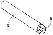
在一些实施方式中,可渗透膜可包括柔性多孔材料的网。例如,如图16所示,可渗透支撑件1240可由柔性多孔材料的网形成,并且设定成形为使得可渗透支撑件1240限定通道1240B。柔性多孔材料可以是例如纺织塑料纤维。纺织塑料纤维可以是例如纺织聚酯纤维,例如用于典型的擦洗垫中的纺织聚酯纤维。可渗透支撑件1240可具有管状形状。可渗透支撑件1240的形状可设定为使得可渗透支撑件1240是圆筒形的或非圆筒形的。如图17所示,其为图16中所示的可渗透支撑件1240沿线17-17剖切的横截面,通道1240B可被成形并配置为接收出口管1220。In some embodiments, a permeable membrane can comprise a mesh of flexible porous material. For example, as shown in FIG. 16,permeable support 1240 may be formed from a mesh of flexible porous material and configured to be shaped such thatpermeable support 1240 defineschannels 1240B. The flexible porous material may be, for example, woven plastic fibers. The woven plastic fibers may be, for example, woven polyester fibers, such as are used in typical scrubbing pads. Thepermeable support 1240 may have a tubular shape. Thepermeable support 1240 can be shaped such that thepermeable support 1240 is cylindrical or non-cylindrical. As shown in FIG. 17 , which is a cross-section ofpermeable support 1240 shown in FIG. 16 taken along line 17 - 17 ,channel 1240B may be shaped and configured to receiveoutlet tube 1220 .

如图18所示,可渗透膜1230可与可渗透支撑件1240连接。可渗透膜1230可在结构和/或功能上与本文所述的任何可渗透膜相同或相似。可渗透支撑件1240可具有第一封闭端1243A和第二封闭端1243B。第二封闭端1243B和可渗透支撑件1240的底部可共同形成贮存器1210,以收集通过可渗透膜1230和可渗透支撑件1240进入通道1240B的流体。出口管1220可插入通道1240B中,使得进入到可渗透支撑件1240中的流体可通过通道1240B和出口管1220(通过例如真空源)从可渗透支撑件1240移除。As shown in FIG. 18 , apermeable membrane 1230 may be attached to apermeable support 1240 .Permeable membrane 1230 may be the same or similar in structure and/or function to any of the permeable membranes described herein. Thepermeable support 1240 can have a firstclosed end 1243A and a secondclosed end 1243B. The secondclosed end 1243B and the bottom of thepermeable support 1240 may collectively form areservoir 1210 to collect fluid passing through thepermeable membrane 1230 and thepermeable support 1240 into thechannel 1240B.Outlet tube 1220 can be inserted intochannel 1240B such that fluid enteringpermeable support 1240 can be removed frompermeable support 1240 throughchannel 1240B and outlet tube 1220 (by, for example, a vacuum source).

在一些实施方式中,柔性多孔材料的网可以是卷曲或折叠成管状的柔性片的形式。例如,如图19所示,可渗透支撑件1340可包括柔性片,该柔性片由柔性多孔材料的网形成,并且卷曲或折叠成使得可渗透支撑件1340限定通道1340B。柔性多孔材料可以是例如纺织塑料纤维。纺织塑料纤维可以是例如纺织聚酯纤维,例如用于典型的擦洗垫中的纺织聚酯纤维。可通过将柔性片的第一端朝向柔性片的第二端卷曲而使得第一端和第二端沿着由1340A标识的交叉平面相遇,使可渗透支撑件1340具有管状形状。然后可用固定元件1352将可渗透支撑件1340以这种形状固定。固定元件1352可包括任何合适的固定元件,例如粘合剂或胶。在一些实施方式中,可渗透支撑件1340可通过来自可渗透膜(例如,下述的可渗透膜1330)的压缩力而被固定在卷曲或折叠配置中,而不是使用一个或多个单独的固定元件1352来固定。可渗透支撑件1340的形状可设定为使得可渗透支撑件1340是圆筒形的或非圆筒形的。如图20所示,其为图19中所示的可渗透支撑件1340沿线20-20剖切的横截面图,通道1340B可成形并配置为接收出口管1320。In some embodiments, the web of flexible porous material may be in the form of a flexible sheet rolled or folded into a tube. For example, as shown in FIG. 19 ,permeable support 1340 may comprise a flexible sheet formed from a mesh of flexible porous material and rolled or folded such thatpermeable support 1340 defineschannel 1340B. The flexible porous material may be, for example, woven plastic fibers. The woven plastic fibers may be, for example, woven polyester fibers, such as are used in typical scrubbing pads. Thepermeable support 1340 may be given a tubular shape by crimping the first end of the flexible sheet towards the second end of the flexible sheet such that the first and second ends meet along an intersecting plane identified by 1340A. Thepermeable support 1340 can then be secured in this shape withfixation elements 1352 .Fixation element 1352 may comprise any suitable fixation element, such as adhesive or glue. In some embodiments, thepermeable support 1340 can be held in a crimped or folded configuration by compressive force from a permeable membrane (eg,permeable membrane 1330 described below), rather than using one or more separate Thefixing element 1352 is used for fixing. Thepermeable support 1340 can be shaped such that thepermeable support 1340 is cylindrical or non-cylindrical. As shown in FIG. 20 , which is a cross-sectional view ofpermeable support 1340 shown in FIG. 19 taken along line 20 - 20 ,channel 1340B may be shaped and configured to receiveoutlet tube 1320 .

如图21所示,可渗透膜1330可与可渗透支撑件1340连接。可渗透膜1330可在结构和/或功能上与本文所述的任何可渗透膜相同或相似。例如,可渗透膜1330可包括芯吸材料,该芯吸材料包裹在可渗透支撑件1340周围。在一些实施方式中,可渗透膜1330可包括芯吸材料,在将柔性多孔材料的网折叠成管状形状之前,该芯吸材料附接或喷涂在所述网上。可渗透支撑件1340可具有第一封闭端1343A和第二封闭端1343B。第二封闭端1343B和可渗透支撑件1340的底部可共同形成贮存器1310,以收集通过可渗透膜1330和可渗透支撑件1340进入通道1340B的流体。出口管1320可插入通道1340B中,使得进入到可渗透支撑件1340中的流体能够通过通道1340B和出口管1320(通过例如真空源)从可渗透支撑件1340移除。As shown in FIG. 21 , apermeable membrane 1330 may be attached to apermeable support 1340 .Permeable membrane 1330 may be the same or similar in structure and/or function to any of the permeable membranes described herein. For example,permeable membrane 1330 may include a wicking material that wraps aroundpermeable support 1340 . In some embodiments, thepermeable membrane 1330 may include a wicking material that is attached or sprayed onto the web of flexible porous material prior to folding the web into a tubular shape. Thepermeable support 1340 can have a firstclosed end 1343A and a secondclosed end 1343B. The secondclosed end 1343B and the bottom of thepermeable support 1340 can collectively form areservoir 1310 to collect fluid passing through thepermeable membrane 1330 and thepermeable support 1340 into thechannel 1340B.Outlet tube 1320 can be inserted intochannel 1340B such that fluid enteringpermeable support 1340 can be removed frompermeable support 1340 throughchannel 1340B and outlet tube 1320 (by, for example, a vacuum source).

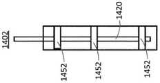
图22-26是以各种配置示出的组件1402的各种图示。如图22-24所示,其分别是组件1402的前视图,后视图和侧视图,在一些实施方式中,可渗透支撑件1440可成形为柔性片。柔性片可由纺织塑料纤维的多孔柔性网形成,所述纺织塑料纤维例如纺织聚酯纤维,比如用于典型的擦洗垫中的纺织聚酯纤维。在一些实施方式中,使用聚酯纤维是因为它能够保持无异味。在一些实施方式中,柔性片可由任何合适类型的纤维形成。出口管1420可通过任何合适的附接机制附接到可渗透支撑件1440上。例如,出口管1420可通过固定元件1452(例如胶带)附接到可渗透支撑件1440上。22-26 are various illustrations ofassembly 1402 shown in various configurations. As shown in Figures 22-24, which are front, rear, and side views, respectively, ofassembly 1402, in some embodiments,permeable support 1440 may be formed as a flexible sheet. The flexible sheet may be formed from a porous, flexible web of woven plastic fibers, such as woven polyester fibers, such as are used in typical scrubbing pads. In some embodiments, polyester fiber is used because of its ability to remain odor free. In some embodiments, the flexible sheet can be formed from any suitable type of fiber.Outlet tube 1420 may be attached topermeable support 1440 by any suitable attachment mechanism. For example, theoutlet tube 1420 may be attached to thepermeable support 1440 by a securingelement 1452 such as adhesive tape.

组件1402可包括不可渗透层1450。如图25所示,其是包括不可渗透层1450的组件1402的侧视图,不可渗透层1450可与可渗透支撑件1440连接,使得通过可渗透支撑件1440的流体可被引向出口管1420的一端。不可渗透层1450可与可渗透支撑件1440组合限定贮存器1410,所述的贮存器1410用于收集通过可渗透支撑件1440进入组件1402并进入组件1402的底部的流体。例如,不可渗透层1450的底端和/或可渗透支撑件1440的底端可以是封闭端,使得除非通过出口管1420(通过例如真空源),否则流体不会离开组件1402。Assembly 1402 may includeimpermeable layer 1450 . As shown in FIG. 25 , which is a side view of anassembly 1402 comprising animpermeable layer 1450 that can be attached to apermeable support 1440 such that fluid passing through thepermeable support 1440 can be directed toward theoutlet tube 1420 one end. Theimpermeable layer 1450 can be combined with thepermeable support 1440 to define areservoir 1410 for collecting fluid that enters theassembly 1402 through thepermeable support 1440 and into the bottom of theassembly 1402 . For example, the bottom end of theimpermeable layer 1450 and/or the bottom end of thepermeable support 1440 may be closed ends such that fluid cannot exit theassembly 1402 except through the outlet tube 1420 (by, for example, a vacuum source).

组件1402还可包括可渗透膜1430。如图26所示,其是组件1402的前视图,可渗透膜1430可设置在可渗透支撑件1440的外表面上或可渗透支撑件1440和背衬1450的外表面上。可渗透膜1430可与本文所述的任何可渗透膜相同或相似。Assembly 1402 may also include apermeable membrane 1430 . As shown in FIG. 26 , which is a front view ofassembly 1402 ,permeable membrane 1430 may be disposed on the outer surface ofpermeable support 1440 or the outer surfaces ofpermeable support 1440 andbacking 1450 .Permeable membrane 1430 can be the same as or similar to any permeable membrane described herein.

在一些实施方式中,贮存器,不可渗透层,和/或出口的一部分可形成为一体式结构。例如,图27和图28分别是不可渗透壳体1504的俯视图和横截面侧视图。不可渗透壳体1504包括不可渗透层1550,出口1520和贮存器1510。出口1520和贮存器1510由不可渗透层1550连接在一起。不可渗透层1550限定长形开口1504A。出口1520可配置为接收管件,使得流体可通过管件从不可渗透壳体1504的内部移除。不可渗透壳体1504可由柔性且柔顺的不可渗透材料形成,例如硅树脂和/或另一种聚合物。此外,不可渗透壳体1504可以是弯曲的,使得在不可渗透壳体1504包括可渗透膜和/或可渗透支撑件的配置中,不可渗透壳体1504可以暴露可渗透膜以获得用于与用户的尿道口接合的舒适且牢固的界面。In some embodiments, a portion of the reservoir, impermeable layer, and/or outlet may be formed as a unitary structure. For example, FIGS. 27 and 28 are top and cross-sectional side views, respectively, of theimpermeable shell 1504 .Impermeable housing 1504 includesimpermeable layer 1550 ,outlet 1520 andreservoir 1510 .Outlet 1520 andreservoir 1510 are connected together byimpermeable layer 1550 . Theimpermeable layer 1550 defines anelongated opening 1504A.Outlet 1520 may be configured to receive tubing such that fluid may be removed from the interior ofimpermeable housing 1504 through the tubing. Theimpermeable shell 1504 may be formed from a flexible and compliant impermeable material, such as silicone and/or another polymer. In addition, theimpermeable shell 1504 can be curved such that in configurations where theimpermeable shell 1504 includes a permeable membrane and/or a permeable support, theimpermeable shell 1504 can expose the permeable membrane for communication with the user. Comfortable and firm interface for articulation of the urethra.

在一些实施方式中,不可渗透壳体1504可配置为包含设置在可渗透支撑件上方的可渗透膜。例如,图29是可渗透支撑件1540的俯视图。可渗透支撑件1540可限定若干个入口1542。入口1542可对称或不对称地横跨可渗透支撑件1540。在一些实施方式中,可渗透支撑件1540可由多孔纺织塑料或塑料网材料形成。可渗透支撑件1540可以是柔性的且柔顺的。在一些实施方式中,可渗透支撑件1540可由柔性聚丙烯、尼龙、聚酯、另一种塑料、天然材料和/或任何其它合适的材料形成。如图30所示,可渗透支撑件1540可折叠或卷曲成管状形状。如图31所示,可渗透支撑件1540可覆盖有可渗透膜1530。例如,可渗透支撑件1540可形成柔性框架,可渗透膜1530可紧密地贴合在所述框架上。In some embodiments, theimpermeable shell 1504 can be configured to include a permeable membrane disposed over a permeable support. For example, FIG. 29 is a top view ofpermeable support 1540 . Thepermeable support 1540 can define a number ofinlets 1542 .Inlet 1542 may be symmetrical or asymmetrical acrosspermeable support 1540 . In some embodiments,permeable support 1540 can be formed from a porous woven plastic or plastic mesh material. Thepermeable support 1540 can be flexible and compliant. In some embodiments,permeable support 1540 may be formed from flexible polypropylene, nylon, polyester, another plastic, natural material, and/or any other suitable material. As shown in Figure 30, thepermeable support 1540 can be folded or rolled into a tubular shape. As shown in FIG. 31 ,permeable support 1540 may be covered withpermeable membrane 1530 . For example,permeable support 1540 may form a flexible frame upon whichpermeable membrane 1530 may fit snugly.

可渗透支撑件1540与可渗透膜1530的组合可设置在不可渗透壳体1504的内部中,使得可渗透支撑件1540可维持可渗透膜1530通过长形开口1504A抵靠或靠近水分源(例如,尿道口)。可渗透膜1530和可渗透支撑件1540可使用任何合适的方法定位在不可渗透壳体1504内。例如,在一些实施方式中,可渗透膜1530可在可渗透支撑件1540上方拉动或包裹在可渗透支撑件1540周围。然后,可渗透膜1530和可渗透支撑件1540的组合可通过不可渗透壳体1504的长形开口1504A插入,并且不可渗透壳体1504可被拉伸和/或以其他方式操纵,使得不可渗透壳体1504包围着可渗透膜1530,长形开口1504A区域除外。The combination ofpermeable support 1540 andpermeable membrane 1530 can be disposed within the interior ofimpermeable housing 1504 such thatpermeable support 1540 can maintainpermeable membrane 1530 through elongatedopening 1504A against or near a moisture source (eg, urethral opening).Permeable membrane 1530 andpermeable support 1540 may be positioned withinimpermeable shell 1504 using any suitable method. For example, in some embodiments,permeable membrane 1530 can be pulled over or wrapped aroundpermeable support 1540 . The combination ofpermeable membrane 1530 andpermeable support 1540 can then be inserted through elongated opening 1504A ofimpermeable shell 1504, andimpermeable shell 1504 can be stretched and/or otherwise manipulated such that theimpermeable shell Body 1504 surroundspermeable membrane 1530, except in the area ofelongated opening 1504A.

在一些实施方式中,可渗透膜1530(例如,管状纱布)可首先设置在中空塑料管(未示出)上。覆盖有可渗透膜1530的管可穿过不可渗透壳体1504的开口1520插入,使得可渗透膜1530定位在不可渗透壳体1504内。然后,可渗透支撑件1540可形成为一种配置,使得可渗透支撑件1540可用作用于可渗透膜1530的中空框架(例如,如图30所示的管状或圆筒形状)。然后可渗透支撑件1540可穿过管和/或开口1520插入,使得可渗透支撑件1540共同延伸并布置在可渗透膜1530内。然后可通过开口1520从可渗透膜1530和可渗透支撑件1540移除管,同时抓住可渗透膜1530和可渗透支撑件1540,使得可渗透膜1530和可渗透支撑件1540保持在不可渗透壳体1504内。In some embodiments, a permeable membrane 1530 (eg, tubular gauze) may first be placed over a hollow plastic tube (not shown). A tube covered withpermeable membrane 1530 can be inserted throughopening 1520 ofimpermeable shell 1504 such thatpermeable membrane 1530 is positioned withinimpermeable shell 1504 . Thepermeable support 1540 can then be formed into a configuration such that thepermeable support 1540 can serve as a hollow frame for the permeable membrane 1530 (eg, a tubular or cylindrical shape as shown in FIG. 30 ).Permeable support 1540 may then be inserted through tube and/oropening 1520 such thatpermeable support 1540 is coextensive and disposed withinpermeable membrane 1530 . The tube can then be removed frompermeable membrane 1530 andpermeable support 1540 throughopening 1520 while graspingpermeable membrane 1530 andpermeable support 1540 such thatpermeable membrane 1530 andpermeable support 1540 remain in the impermeable shell Inbody 1504.

在一些实施方式中,可渗透膜1530(例如,管状纱布)可首先设置在中空塑料管(未示出)上。然后,可渗透支撑件1540可形成为一种配置,使得可渗透支撑件1540可用作用于可渗透膜1530的中空框架(例如,如图30所示的管状或圆筒形状)。然后可渗透支撑件1540可穿过管插入,使得可渗透支撑件1540共同延伸并布置在可渗透膜1530内。然后可从可渗透膜1530和可渗透支撑件1540移除管,同时抓住可渗透膜1530和可渗透支撑件1540,使得可渗透膜1530和可渗透支撑件1540保持在不可渗透壳体1504内。如果可渗透膜1530比所需的长,例如如果可渗透膜1530比可渗透支撑件1540长,则可将可渗透膜1530(例如,用剪刀)剪切成所期望的长度。然后,可渗透支撑件1540与可渗透膜1530的组合可通过长形开口1504A插入不可渗透壳体1504中。In some embodiments, a permeable membrane 1530 (eg, tubular gauze) may first be placed over a hollow plastic tube (not shown). Thepermeable support 1540 can then be formed into a configuration such that thepermeable support 1540 can serve as a hollow frame for the permeable membrane 1530 (eg, a tubular or cylindrical shape as shown in FIG. 30 ). Thepermeable support 1540 can then be inserted through the tube such that thepermeable support 1540 is coextensive and disposed within thepermeable membrane 1530 . The tube can then be removed frompermeable membrane 1530 andpermeable support 1540 while graspingpermeable membrane 1530 andpermeable support 1540 such thatpermeable membrane 1530 andpermeable support 1540 remain withinimpermeable housing 1504 . Ifpermeable membrane 1530 is longer than desired, eg, ifpermeable membrane 1530 is longer thanpermeable support 1540,permeable membrane 1530 may be cut (eg, with scissors) to the desired length. The combination ofpermeable support 1540 andpermeable membrane 1530 can then be inserted intoimpermeable shell 1504 through elongatedopening 1504A.

在一些实施方式中,可渗透膜1530可通过粘合剂或胶带附接到可渗透支撑件1540上。在一些实施方式中,可渗透膜1530可通过来自不可渗透壳体1504的压缩力而附接到可渗透支撑件1540上。例如,可渗透膜1530可包裹在可渗透支撑件1540周围并插入不可渗透壳体1504内,使得不可渗透壳体1504对可渗透膜1530和可渗透支撑件1540施加压缩力,使得可渗透膜1530和可渗透支撑件1540各自保持其形状并彼此附接。在一些实施方式中,由于可渗透膜1530具有弹性性质,导致可渗透膜1530可通过压缩固定到可渗透支撑件1540上。例如,可渗透膜1530可包括管状压缩纱布,其可作为套筒施用于可渗透支撑件1540。In some embodiments,permeable membrane 1530 can be attached topermeable support 1540 by adhesive or tape. In some embodiments,permeable membrane 1530 can be attached topermeable support 1540 by compressive force fromimpermeable shell 1504 . For example,permeable membrane 1530 may be wrapped aroundpermeable support 1540 and inserted intoimpermeable shell 1504 such thatimpermeable shell 1504 exerts a compressive force onpermeable membrane 1530 andpermeable support 1540 such thatpermeable membrane 1530 andpermeable supports 1540 each retain their shape and are attached to each other. In some embodiments, thepermeable membrane 1530 can be secured to thepermeable support 1540 by compression due to the elastic properties of thepermeable membrane 1530 . For example,permeable membrane 1530 may comprise a tubular compressed gauze that may be applied topermeable support 1540 as a sleeve.

图32是组件1602的横截面图。组件1602可包括不可渗透壳体1604。不可渗透壳体1604可在结构和/或功能上与参考图27和图28描述的上述不可渗透壳体1504相同或相似。例如,不可渗透壳体1604可包括贮存器1610,不可渗透背衬1650和出口1620。此外,组件1602可包括可渗透膜1630和可渗透支撑件1640。可渗透膜1630和可渗透支撑件1640分别可在结构和功能上与本文所述的可渗透膜和可渗透支撑件相同或相似。例如,可渗透膜1630可以是罗纹针织织物套筒,并且可渗透支撑件1640可由管状的纺织塑料(例如,可渗透的无纺布织带)形成。因此,组件1602可以是柔韧的和/或柔性的,使得组件1602可顺应不同形状和/或尺寸的用户,以确保组件1602的有效和牢固的放置。组件1602可包括与出口1620相关联的管1621,使得贮存器1610中的流体可通过例如在真空源(未示出)的作用下流过管1621并排出出口1620而被移除。FIG. 32 is a cross-sectional view ofassembly 1602 .Assembly 1602 may include animpermeable shell 1604 . Theimpermeable shell 1604 may be the same or similar in structure and/or function to theimpermeable shell 1504 described above with reference to FIGS. 27 and 28 . For example,impermeable shell 1604 may includereservoir 1610 ,impermeable backing 1650 andoutlet 1620 . Additionally,assembly 1602 can include apermeable membrane 1630 and apermeable support 1640 .Permeable membrane 1630 andpermeable support 1640 can be identical or similar in structure and function to the permeable membrane and permeable support described herein, respectively. For example, thepermeable membrane 1630 can be a sleeve of rib-knit fabric, and thepermeable support 1640 can be formed from a tubular woven plastic (eg, a permeable non-woven webbing). Accordingly,assembly 1602 may be pliable and/or flexible such thatassembly 1602 may conform to users of different shapes and/or sizes to ensure effective and secure placement ofassembly 1602 .Assembly 1602 may include atube 1621 associated withoutlet 1620 such that fluid inreservoir 1610 may be removed by flowing throughtube 1621 and outoutlet 1620, eg, under the action of a vacuum source (not shown).

图33是与女性身体接合的组件1602的横截面侧视图。如图33所示,组件1602可布置为靠近尿道,使得组件1602的长形开口1604A面向尿道口。此外,组件1602可放置在用户的阴唇之间,并且通过来自用户身体的摩擦力保持紧密地抵靠或靠近尿道。此外,如图33所示,组件1602可以是弯曲的,使得组件1602提供用于与用户的尿道口和用户身体的周围区域接合的舒适且牢固的界面,其中长形开口位于曲线的内侧。因此,在尿液从用户的身体排出时,尿液可通过长形开口1604A、可渗透膜1630以及可渗透支撑件1640的入口流入组件1602。然后,由于重力和/或由真空源通过管1621提供的吸力,尿液可流到组件1602的贮存器1610。然后,由真空源提供的吸力可从贮存器1610抽出尿液,使尿液流过管1621,并流出组件1602。Figure 33 is a cross-sectional side view ofassembly 1602 engaged with a female body. As shown in FIG. 33, theassembly 1602 can be placed proximate the urethra such that theelongated opening 1604A of theassembly 1602 faces the urethral opening. Additionally,assembly 1602 may be placed between the user's labia and held tightly against or near the urethra by friction from the user's body. Additionally, as shown in FIG. 33,assembly 1602 may be curved such thatassembly 1602 provides a comfortable and secure interface for engaging the user's urethral meatus and surrounding areas of the user's body, with the elongated opening on the inside of the curve. Thus, urine may flow intoassembly 1602 through elongatedopening 1604A,permeable membrane 1630 , and inlet ofpermeable support 1640 as it exits the user's body. Urine may then flow toreservoir 1610 ofassembly 1602 due to gravity and/or suction provided by a vacuum source throughtube 1621 . Suction provided by a vacuum source may then draw the urine fromreservoir 1610 , causing the urine to flow throughtube 1621 and out ofassembly 1602 .

组件1602可具有任何合适的大小,使得组件1602可配置成与不同尺寸和/或解剖结构的用户的尿道口和/或尿道口周围区域接合。例如,在一些实施例中,不可渗透壳体1604的长度(即,从贮存器1610的顶端到出口1620中的开口)范围可为约7英寸至约8英寸。在一些实施例中,例如对于体型较大的患者,不可渗透壳体1604的长度范围可为约9英寸至约10英寸。在一些实施例中,例如对于体型较小的成人患者或儿童,不可渗透壳体1604的长度范围可为约3英寸至约5英寸。在一些实施例中,不可渗透壳体1604的长度范围可为约3英寸至约10英寸。长形开口1604的长度范围可为约5英寸至约6英寸。在一些实施例中,不可渗透壳体1604的直径可为约1英寸。在一些实施例中,不可渗透壳体1604的直径范围可为约0.5英寸至约1.5英寸。相对于不可渗透壳体1604的高度(即直径),长形开口1604A可具有约1英寸的宽度和约0.5英寸的深度。可渗透支撑件1640的直径可为约0.875英寸。出口1620可为约0.25英寸长,和约0.5英寸宽。出口1620的开口的直径可为约0.375英寸。此外,管1621的直径可为约0.375英寸。Assembly 1602 may be of any suitable size such thatassembly 1602 may be configured to engage the meatus and/or the region surrounding the meatus of users of different sizes and/or anatomies. For example, in some embodiments, the length of impermeable housing 1604 (ie, from the top end ofreservoir 1610 to the opening in outlet 1620 ) may range from about 7 inches to about 8 inches. In some embodiments, such as for larger patients, theimpermeable shell 1604 may have a length ranging from about 9 inches to about 10 inches. In some embodiments, theimpermeable shell 1604 may range in length from about 3 inches to about 5 inches, such as for a small adult patient or child. In some embodiments, theimpermeable shell 1604 may range in length from about 3 inches to about 10 inches. The length of theelongated opening 1604 may range from about 5 inches to about 6 inches. In some embodiments, theimpermeable shell 1604 may be about 1 inch in diameter. In some embodiments, theimpermeable shell 1604 may range in diameter from about 0.5 inches to about 1.5 inches. Relative to the height (ie, diameter) ofimpermeable shell 1604, elongated opening 1604A may have a width of about 1 inch and a depth of about 0.5 inches. The diameter of thepermeable support 1640 may be about 0.875 inches. Theoutlet 1620 may be about 0.25 inches long, and about 0.5 inches wide. The diameter of the opening ofoutlet 1620 may be about 0.375 inches. Additionally, the diameter oftube 1621 may be about 0.375 inches.

此外,组件1602可包括任何合适的曲线,使得组件1602可与用户的尿道口和/或尿道口周围区域接合。例如,在一些实施例中,组件1602和/或不可渗透壳体1604的曲率角可为约40°。在一些实施例中,组件1602和/或不可渗透壳体1604的曲率角可为约60°。在一些实施例中,组件1602和/或不可渗透壳体1604的曲率半径可在约6英寸至约10英寸范围内。Additionally,assembly 1602 may include any suitable curve such thatassembly 1602 may engage the user's urethral opening and/or the area surrounding the urethral opening. For example, in some embodiments, the angle of curvature ofassembly 1602 and/orimpermeable shell 1604 may be about 40°. In some embodiments, the angle of curvature ofassembly 1602 and/orimpermeable shell 1604 may be about 60°. In some embodiments, the radius of curvature ofassembly 1602 and/orimpermeable shell 1604 may be in the range of about 6 inches to about 10 inches.

在一些实施例中,可渗透膜1630和/或可渗透支撑件1640可完全地设置在不可渗透壳体1604内,使得可渗透膜1630和/或可渗透支撑件1640不穿过长形开口1604A延伸。在一些实施例中,可渗透膜1630和/或可渗透支撑件1640可设置在不可渗透壳体1604内,使得可渗透膜1630的一部分和/或可渗透支撑件1640的一部分穿过长形开口1604A延伸。In some embodiments,permeable membrane 1630 and/orpermeable support 1640 may be disposed entirely withinimpermeable shell 1604 such thatpermeable membrane 1630 and/orpermeable support 1640 do not pass throughelongated opening 1604A extend. In some embodiments,permeable membrane 1630 and/orpermeable support 1640 may be disposed withinimpermeable housing 1604 such that a portion ofpermeable membrane 1630 and/or a portion ofpermeable support 1640 passes through theelongated opening 1604A extension.

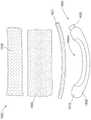
图34是组件1802的部件的爆炸图。组件1802可在结构和/或功能上与上述组件1602相同或相似。例如,组件1802包括不可渗透壳体1804。不可渗透壳体1804可在结构和/或功能上与不可渗透壳体1604和/或不可渗透壳体1504相同或相似。不可渗透壳体1804可包括贮存器1810,不可渗透背衬1850和出口1820。此外,组件1802可包括可渗透膜1830和可渗透支撑件1840。可渗透膜1830和可渗透支撑件1840可分别在结构和/或功能上与本文所述的可渗透膜和可渗透支撑件相同或相似。例如,可渗透膜1830可以是罗纹针织织物套筒,并且可渗透支撑件1840可由柔性的纺织塑料片(例如,可渗透的无纺布织带)形成,其可折叠或卷曲,从而使得可渗透支撑件1840形成为管状。因此,组件1802可以是柔韧的和/或柔性的,使得组件1802可顺应不同形状和/或尺寸的用户,以确保组件1802的有效和牢固的放置。组件1802可包括与出口1820相关联的管1821,使得贮存器1810中的流体可通过在例如真空源(未示出)的作用下流过管1821并排出出口1820而被移除。FIG. 34 is an exploded view of the components ofassembly 1802 .Component 1802 may be identical or similar in structure and/or function tocomponent 1602 described above. For example,assembly 1802 includesimpermeable shell 1804 .Impermeable shell 1804 may be identical or similar in structure and/or function toimpermeable shell 1604 and/orimpermeable shell 1504 . Theimpermeable shell 1804 may include areservoir 1810 , animpermeable backing 1850 and anoutlet 1820 . Additionally,assembly 1802 can include apermeable membrane 1830 and apermeable support 1840 .Permeable membrane 1830 andpermeable support 1840 may be identical or similar in structure and/or function to the permeable membrane and permeable support described herein, respectively. For example,permeable membrane 1830 may be a sleeve of rib-knit fabric, andpermeable support 1840 may be formed from a flexible sheet of woven plastic (eg, a permeable non-woven webbing) that may be folded or crimped such that the permeable support Themember 1840 is formed in a tubular shape. Accordingly,assembly 1802 may be pliable and/or flexible such thatassembly 1802 may conform to users of different shapes and/or sizes to ensure effective and secure placement ofassembly 1802 .Assembly 1802 may include atube 1821 associated withoutlet 1820 such that fluid inreservoir 1810 may be removed by flowing throughtube 1821 and outoutlet 1820 under, for example, a vacuum source (not shown).

图35是处于组装配置中的组件1802的侧视图,如图所示,可渗透支撑件1840可折叠或卷曲使得其形状从片状变为管状。可渗透膜1830可在可渗透支撑件1840上拉动。然后,可渗透膜1830和可渗透支撑件1840的组合可穿过不可渗透壳体1804的长形开口1804A插入,并且不可渗透壳体1804可被拉伸和/或以其他方式操纵,使得不可渗透壳体1804包围可渗透膜1830,但长形开口1804A区域除外。管件1821可通过出口1820插入,使得该管件设置在由可渗透支撑件1840限定的通道中,且管件的一端位于贮存器1810中。在一些实施方式中,在将可渗透支撑件1840和可渗透膜1830穿过长形开口1804A插入之前,管件1821可插入由可渗透支撑件1840限定的通道中。管件1821可穿过长形开口1804A并穿过开口1820,并且不可渗透背衬1804的贮存器1810可绕管件1821的相对端、可渗透支撑件1840和可渗透膜1830拉动。35 is a side view ofassembly 1802 in an assembled configuration, as shown,permeable support 1840 can be folded or crimped so that its shape changes from a sheet to a tube. Thepermeable membrane 1830 can be pulled on thepermeable support 1840 . The combination ofpermeable membrane 1830 andpermeable support 1840 can then be inserted through elongated opening 1804A ofimpermeable shell 1804, andimpermeable shell 1804 can be stretched and/or otherwise manipulated to renderimpermeable Housing 1804 surroundspermeable membrane 1830, except in the area ofelongated opening 1804A.Tubing 1821 can be inserted throughoutlet 1820 such that the tubing is disposed in the channel defined bypermeable support 1840 with one end of the tubing located inreservoir 1810 . In some embodiments, thetubing 1821 can be inserted into the channel defined by thepermeable support 1840 prior to inserting thepermeable support 1840 andpermeable membrane 1830 through theelongated opening 1804A.Tubing 1821 can be passed throughelongated opening 1804A and throughopening 1820 , andreservoir 1810 ofimpermeable backing 1804 can be pulled around the opposite end oftubing 1821 ,permeable support 1840 andpermeable membrane 1830 .

在一些实施方式中,不可渗透层可限定有一个或多个真空释放开口。例如,图40是不可渗透壳体2004的后视图。不可渗透壳体2004可与图34和图35所示和参考这两个附图所描述的不可渗透壳体1804相同或相似。不可渗透壳体2004可包括贮存器2010,不可渗透背衬2050和出口2020。不可渗透壳体2004还可包括真空释放开口2058。因此,在用户的身体包住包括不可渗透层2050的组件(例如与组件1802相同或相似的组件)的情况下,一个或多个真空释放开口2058可防止抵靠用户皮肤的吸力增加,这可能是不舒服或疼痛的。例如,不可渗透壳体2004可限定与上述长形开口1804A相同或相似的长形开口(未示出)。真空释放开口2058可位于不可渗透壳体2004的两端之间,使得在用户的身体阻塞一部分或整个长形开口的情况下,组件中至少存在一个额外的气流路径。尽管图中所示为位于出口2020附近,但真空释放开口2058可设置在不可渗透层2050上的任何合适位置处。在一些实施方式中,一个或多个真空释放开口2058可设置在使用户的阴唇或大腿的皮肤无意中覆盖孔的可能性降低的位置,例如靠近出口2020的位置。此外,不可渗透壳体2004可包括任何合适数量的真空释放开口2058。In some embodiments, the impermeable layer may define one or more vacuum release openings. For example, FIG. 40 is a rear view ofimpermeable shell 2004 . Theimpermeable shell 2004 may be the same as or similar to theimpermeable shell 1804 shown in and described with reference to FIGS. 34 and 35 . Theimpermeable shell 2004 may include areservoir 2010 , animpermeable backing 2050 and anoutlet 2020 . Theimpermeable shell 2004 may also include avacuum relief opening 2058 . Accordingly, the one or morevacuum relief openings 2058 may prevent increased suction against the user's skin, which may is uncomfortable or painful. For example,impermeable shell 2004 may define an elongated opening (not shown) that is the same as or similar toelongated opening 1804A described above. Thevacuum relief opening 2058 may be located between the ends of theimpermeable shell 2004 such that there is at least one additional airflow path through the assembly in the event that a portion or the entire elongated opening is obstructed by the user's body. Although shown nearoutlet 2020 ,vacuum relief opening 2058 may be positioned at any suitable location onimpermeable layer 2050 . In some embodiments, the one or morevacuum relief openings 2058 may be positioned such that the skin of the user's labia or thighs is less likely to inadvertently cover the aperture, such as near theoutlet 2020 . Additionally,impermeable shell 2004 may include any suitable number ofvacuum relief openings 2058 .

在一些实施方式中,组件可包括包含胶带的不可渗透背衬,而不包括不可渗透壳体。例如,图36是组件1702的分解图。组件1702包括贮存器1710,可渗透支撑件1740,可渗透性膜1730和管1721。组件1702可在结构和/或功能上与参考图32和图33描述的上述组件1602相似。例如,可渗透膜1730和可渗透支撑件1740可与本文所述的任何可渗透膜和可渗透支撑件相同或相似。例如,可渗透支撑件1740可以是柔性的纺织塑料片(例如,无纺布可渗透的带状物)。因此,组件1702可以是柔韧的和/或柔性的,使得组件1702可顺应不同形状和/或尺寸的用户,以确保组件1702的有效和牢固的放置。在一些实施方式中,可渗透膜1730可以是罗纹针织织物套筒。此外,管1721可与出口(例如,图38中的出口1720)相关联,用于使流体从贮存器1710抽出并抽入外部接收器(例如参考图1所展示和描述的外部接收器160)。贮存器1710可包括柔性盖并且可配置成通过不可渗透背衬(例如,图28中的不可渗透背衬1750)附接到可渗透膜1730和/或可渗透支撑件上。In some embodiments, an assembly may include an impermeable backing comprising an adhesive tape, rather than an impermeable shell. For example, FIG. 36 is an exploded view ofassembly 1702 .Assembly 1702 includesreservoir 1710 ,permeable support 1740 ,permeable membrane 1730 andtube 1721 .Component 1702 may be similar in structure and/or function tocomponent 1602 described above with reference to FIGS. 32 and 33 . For example,permeable membrane 1730 andpermeable support 1740 can be the same as or similar to any of the permeable membranes and permeable supports described herein. For example,permeable support 1740 may be a flexible sheet of woven plastic (eg, a non-woven permeable ribbon). Accordingly,assembly 1702 may be pliable and/or flexible such thatassembly 1702 may conform to users of different shapes and/or sizes to ensure effective and secure placement ofassembly 1702 . In some embodiments,permeable membrane 1730 can be a sleeve of rib knit fabric. In addition, atube 1721 can be associated with an outlet (eg,outlet 1720 in FIG. 38 ) for drawing fluid from thereservoir 1710 and into an external receptacle (such as theexternal receptacle 160 shown and described with reference to FIG. 1 ). .Reservoir 1710 can include a flexible cover and can be configured to be attached topermeable membrane 1730 and/or a permeable support via an impermeable backing (eg,impermeable backing 1750 in FIG. 28 ).

如图37所示,其是局部组装的组件1702的侧视图,可渗透支撑件1840可折叠或卷曲使得其形状从片状变为管状。然后可渗透支撑件1840可插入贮存器1710(例如,柔性盖)中。管1721可通过由可渗透支撑件1840形成的通道插入并进入贮存器1710。As shown in Figure 37, which is a side view of the partially assembledassembly 1702, thepermeable support 1840 can be folded or crimped so that its shape changes from a sheet to a tube. Thepermeable support 1840 can then be inserted into the reservoir 1710 (eg, a flexible cover).Tube 1721 can be inserted through the channel formed bypermeable support 1840 and intoreservoir 1710 .

如图38所示,组件1702可包括不可渗透背衬1750,所述不可渗透背衬1750包括胶带。不可渗透背衬1750可包括由背衬部分1753连接的两个固定部分1752A和1752B。固定部分1752A和固定部分1752B与背衬部分1753组合可限定有长形开口1704A,流体(例如尿液)可通过长形开口1704A流入组件1702。此外,固定部分1752A可用于将贮存器1710固定到背衬部分1753、可渗透膜1730和/或可渗透支撑件1740上(如图36和图37所示)。在一些实施方式中,固定部分1752B与管1721组合可形成出口1720的一部分或全部。因此,不可渗透背衬1750可引导流体流过组件1702,使得通过长形开口1704A进入可渗透膜1730和可渗透支撑件1740的流体除非通过管1721否则不会离开组件1702。在使用中,流体可由于重力和/或吸力的作用而向贮存器1710流动并被贮存器1710和不可渗透背衬1750容纳。然后,管1721可用于将流体抽出组件1702(通过例如真空源)。此外,不可渗透背衬1750可帮助限制正经受来自真空源的吸力的可渗透膜1730区域,使得压力差更大并且使得流体可有效地穿过可渗透膜1730被抽出。As shown in FIG. 38,assembly 1702 may include animpermeable backing 1750 comprising an adhesive tape.Impermeable backing 1750 may include two fixation portions 1752A and 1752B connected by backingportion 1753 . Securement portion 1752A and securement portion 1752B in combination withbacking portion 1753 can define an elongated opening 1704A through which fluid (eg, urine) can flow intoassembly 1702 . Additionally, securing portion 1752A may be used to securereservoir 1710 tobacking portion 1753,permeable membrane 1730, and/or permeable support 1740 (as shown in FIGS. 36 and 37). In some embodiments, fixed portion 1752B in combination withtube 1721 may form part or all ofoutlet 1720 . Thus,impermeable backing 1750 can direct fluid flow throughassembly 1702 such that fluid enteringpermeable membrane 1730 andpermeable support 1740 through elongated opening 1704A does not exitassembly 1702 unless passing throughtube 1721 . In use, fluid may flow toward and be contained byreservoir 1710 andimpermeable backing 1750 due to gravity and/or suction.Tube 1721 may then be used to draw fluid out of assembly 1702 (via, for example, a vacuum source). Additionally, theimpermeable backing 1750 can help limit the area of thepermeable membrane 1730 that is experiencing suction from the vacuum source so that the pressure differential is greater and fluid can be efficiently drawn through thepermeable membrane 1730 .

图39是根据一个实施例的、使用一组件来从用户收集尿液的方法的流程图。方法1900可选地包括,在1902,将尿液收集装置的管的排出端与流体接收器流体连接。方法1900还可选地包括,在1904,将尿液收集装置的管的排出端与真空源流体连接。方法1900还包括,在1906,将尿液收集装置设置为与雌性用户(例如人或动物)的尿道口与呈操作关系。尿液收集装置可在结构和/或功能上与本文所述的任何尿液收集装置相同或相似,例如图1中的组件102。例如,尿液收集装置可包括流体不可渗透壳体,流体可渗透支撑件,流体可渗透膜和管。流体不可渗透壳体可具有在第一端的流体贮存器,在第二端的流体出口。纵向延伸的流体不可渗透层可与流体贮存器和流体出口连接,并且可在流体贮存器和流体出口之间限定纵向的长形开口。流体可渗透支撑件可设置在壳体内,其中流体可渗透支撑件的一部分横跨长形开口延伸。流体可渗透膜可设置在支撑件上并且可至少覆盖支撑件横跨长形开口延伸的部分,使得膜支撑在支撑件上并且横跨长形开口设置。管可具有设置在贮存器中的第一端,和第二流体排出端。管可至少在横跨长形开口设置的支撑件的部分和膜的部分的后方延伸,并且可穿过流体出口延伸至第二流体排出端。操作关系可包括开口与所述雌性用户的尿道口邻近。Figure 39 is a flowchart of a method of using an assembly to collect urine from a user, according to one embodiment.Method 1900 optionally includes, at 1902, fluidly connecting a discharge end of a tube of a urine collection set with a fluid receiver.Method 1900 also optionally includes, at 1904, fluidly connecting the discharge end of the tubing of the urine collection set to a vacuum source.Method 1900 also includes, at 1906, disposing a urine collection device in operative relationship with a urethral opening of a female user (eg, human or animal). The urine collection device may be the same or similar in structure and/or function to any urine collection device described herein, such asassembly 102 in FIG. 1 . For example, a urine collection device may include a fluid-impermeable housing, a fluid-permeable support, a fluid-permeable membrane, and a tube. The fluid impermeable housing may have a fluid reservoir at a first end and a fluid outlet at a second end. A longitudinally extending fluid-impermeable layer can be connected to the fluid reservoir and the fluid outlet, and can define a longitudinally elongated opening between the fluid reservoir and the fluid outlet. A fluid permeable support may be disposed within the housing with a portion of the fluid permeable support extending across the elongated opening. The fluid permeable membrane may be disposed on the support and may cover at least a portion of the support extending across the elongated opening such that the membrane is supported on the support and disposed across the elongated opening. The tube may have a first end disposed in the reservoir, and a second fluid discharge end. The tube may extend at least behind the portion of the support and the portion of the membrane disposed across the elongated opening and may extend through the fluid outlet to the second fluid discharge end. The operative relationship may include the opening being adjacent to the female user's urethral opening.

方法1900还包括,在1908,允许从尿道口排出的尿液流过流体不可渗透层的开口、膜、支撑件并流入贮存器而被接收。Method 1900 also includes, at 1908, allowing urine expelled from the urethral opening to flow through the opening of the fluid-impermeable layer, the membrane, the support and into the reservoir to be received.

方法1900还包括,在1910,允许所接收的尿液经由管从贮存器排出,并从管的流体排出端排出。Method 1900 also includes, at 1910, allowing the received urine to drain from the reservoir via the tube and out the fluid discharge end of the tube.

方法1900可选地包括,在1912,将尿液收集装置从与用户的尿道口的操作关系中移除。Method 1900 optionally includes, at 1912, removing the urine collection device from operative relationship with the user's urethral opening.

最后,方法1900可选地包括,在1914,设置第二尿液收集装置,使其与用户的尿道口呈操作关系。Finally,method 1900 optionally includes, at 1914, positioning a second urine collection device in operative relationship with the user's urethral opening.

在一些实施例中,支撑件和壳体可以是圆筒形的并且可具有弯曲形状,其中长形开口设置在曲线的内侧。所述设置可包括将尿液收集装置设置成使长形开口邻近用户的尿道口,和将贮存器定向为靠近用户的肛门,并且将所述出口设置在尿道口上方。In some embodiments, the support and housing may be cylindrical and may have a curved shape with the elongated openings disposed on the inside of the curve. The positioning may include positioning the urine collection device with the elongated opening adjacent to the user's urethral opening, and orienting the reservoir proximate to the user's anus, and positioning the outlet above the urethral opening.

在一些实施例中,组件(例如,图32中所示的组件1602)可具有弯曲形状,该弯曲形状至少部分地由形状保持构件限定或维持。在一些实施例中,形状保持构件可实施为管,所述管具有定位在贮存器内的进气端,使得管从贮存器延伸并穿过可渗透支撑件的至少一部分,类似于例如图32和图33所示的管1621,该管1621具有预弯曲形状,使得至少包括管的组件的部分也将具有类似或相应的预弯曲形状。例如,如图41所示,管2121是预弯曲的。管2121可在结构上和/或功能上与本文所述的任何管相同或相似,例如管1621,管1721,和/或管1821。管2121可预先弯曲成任何合适的弯曲形状(例如,任何合适的曲率角),使得例如包括管2121的组件可与用户的尿道口和/或尿道口周围区域接合。In some embodiments, an assembly (eg,assembly 1602 shown in FIG. 32 ) can have a curved shape that is at least partially defined or maintained by a shape-maintaining member. In some embodiments, the shape-retaining member may be implemented as a tube having an inlet end positioned within the reservoir such that the tube extends from the reservoir and through at least a portion of the permeable support, similar to, for example, FIG. 32 As with thetube 1621 shown in Figure 33, thetube 1621 has a pre-bent shape such that at least the portion of the assembly comprising the tube will also have a similar or corresponding pre-bend shape. For example, as shown in Figure 41, thetube 2121 is pre-bent.Tube 2121 can be identical or similar in structure and/or function to any tube described herein, such astube 1621 ,tube 1721 , and/ortube 1821 .Tube 2121 may be pre-bent into any suitable curved shape (eg, any suitable angle of curvature) such that, for example, anassembly including tube 2121 may engage the user's urethral opening and/or the area surrounding the urethral opening.

在一些实施方式中,管2121最初可被成形为使得其具有未弯曲(即,直的)的整体形状。然后管2121可通过例如热定型而弯曲。换而言之,管2121可由直形的硬质或刚性材料(如硬质塑料)形成。管2121可被加热使得管2121软化,然后可将管2121弯曲成预定的弯曲形状。弯曲之后,可将管2121冷却,以使管2121硬化。In some embodiments, thetube 2121 may initially be shaped such that it has an unbent (ie, straight) overall shape. Thetube 2121 can then be bent, eg by heat setting. In other words,tube 2121 may be formed from a straight hard or rigid material such as hard plastic. Thetube 2121 may be heated to soften thetube 2121, and then thetube 2121 may be bent into a predetermined bent shape. After bending, thetube 2121 may be cooled so that thetube 2121 hardens.

在一些实施方式中,管2121可预弯曲,通过首先形成管2121使得管2121为直形,然后使管2121弯曲超过管2121的弹性极限,使得管2121具有预设曲线。例如,管2121可由诸如金属的材料形成,该材料在弯曲成弯曲形状之后将保持弯曲形状。In some embodiments, thetube 2121 can be pre-bent by first forming thetube 2121 such that thetube 2121 is straight and then bending thetube 2121 beyond the elastic limit of thetube 2121 so that thetube 2121 has a preset curve. For example,tube 2121 may be formed from a material, such as metal, that will retain the curved shape after being bent into the curved shape.

在一些实施例中,组件(例如,图32中所示的组件1602)可具有弯曲形状,该弯曲形状至少部分地由形状保持构件限定或维持,该形状保持构件与管分离,该管具有在贮存器中的进气端。因此,组件可具有管,和用于将组件或组件的一部分维持为预弯曲形状的分离的形状保持元件。例如,如图42所示,形状保持元件2251可具有预弯曲形状。形状保持元件2251可由例如半刚性材料条形成。形状保持元件2251可附接到组件任何合适的部分。例如,在一些实施方式中,形状保持元件2251可附接到不可渗透层(例如不可渗透层1650)的内表面上。在一些实施方式中,形状保持元件2251可设置在不可渗透层(例如不可渗透层1650)与可渗透支撑件(例如可渗透支撑件1640)和/或可渗透膜(例如可渗透膜1630)之间。在一些实施方式中,形状保持元件2251可附接到不可渗透层(例如不可渗透层1650)的外表面上,或可嵌入不可渗透层(例如不可渗透层1650)中。In some embodiments, an assembly (eg,assembly 1602 shown in FIG. 32 ) can have a curved shape that is at least partially defined or maintained by a shape-retaining member that is separate from the tube that has Inlet port in the reservoir. Thus, the assembly may have a tube, and a separate shape retaining element for maintaining the assembly or part of the assembly in a pre-bent shape. For example, as shown in FIG. 42, theshape retaining element 2251 may have a pre-curved shape. Theshape retaining element 2251 may be formed, for example, from a strip of semi-rigid material. Theshape retaining element 2251 may be attached to any suitable portion of the assembly. For example, in some embodiments,shape retaining element 2251 can be attached to an inner surface of an impermeable layer (eg, impermeable layer 1650 ). In some embodiments,shape retaining element 2251 can be disposed between an impermeable layer (eg, impermeable layer 1650 ) and a permeable support (eg, permeable support 1640 ) and/or a permeable membrane (eg, permeable membrane 1630 ). between. In some embodiments,shape retaining element 2251 can be attached to an outer surface of an impermeable layer (eg, impermeable layer 1650 ), or can be embedded in an impermeable layer (eg, impermeable layer 1650 ).

在一些实施例中,管具有定位在贮存器内的进气端,使得管从贮存器延伸并穿过可渗透支撑件的至少一部分,类似于例如图32和图33所示的管1621,该管可具有倾斜进气端(即倾斜的贮存器端)。如图43所示,管2321包括倾斜进气端2323。管2321可在结构上和/或功能上与本文所述的任何管相似,例如管1621,管1721,管1821和/或管2121。倾斜进气端2323可防止管2321在操作中堵塞。例如,倾斜进气端2323可增加管2321的进气开口2325的尺寸,使得进气开口2325不太可能被障碍物堵塞。此外,倾斜进气端2323可防止管2323在进气端被形成贮存器的材料阻塞。例如,在其中贮存器由柔性和/或柔韧材料形成而作为壳体的一部分(例如图35中的壳体1804的贮存器1810)的组件中,通过管1821的真空所产生的吸力和/或施加到贮存器外部的力可以使贮存器1810的材料朝向管1821的进气端移动、并阻塞和/或密封管1821的进气端,阻止流体流过管1821的进气端。由于成角度的顶端,管2321的倾斜进气端可防止阻塞发生。即使贮存器(例如,1810)的一部分弯曲成与管2321的远端接触,进气开口2325也能保持至少部分或完全不被阻塞。In some embodiments, the tube has an inlet end positioned within the reservoir such that the tube extends from the reservoir and through at least a portion of the permeable support, similar to, for example,tube 1621 shown in FIGS. 32 and 33 , which The tube may have a sloped inlet end (ie sloped reservoir end). As shown in FIG. 43 , thetube 2321 includes a slopedinlet end 2323 .Tube 2321 may be similar in structure and/or function to any of the tubes described herein, such astube 1621 ,tube 1721 ,tube 1821 and/ortube 2121 . Sloping theinlet end 2323 prevents thetube 2321 from clogging during operation. For example, sloping theintake end 2323 can increase the size of theintake opening 2325 of thetube 2321 such that theintake opening 2325 is less likely to be blocked by obstructions. Additionally, sloping theinlet end 2323 prevents thetube 2323 from clogging at the inlet end with the material forming the reservoir. For example, in an assembly in which the reservoir is formed from a flexible and/or pliable material as part of the housing (such asreservoir 1810 ofhousing 1804 in FIG. A force applied to the outside of the reservoir can move the material of thereservoir 1810 toward the inlet end of thetube 1821 and block and/or seal the inlet end of thetube 1821 preventing fluid flow through the inlet end of thetube 1821 . The angled inlet end of thetube 2321 prevents clogging due to the angled tip. Even if a portion of the reservoir (eg, 1810) bends into contact with the distal end of thetube 2321, theinlet opening 2325 remains at least partially or completely unobstructed.

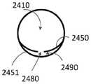
在一些实施例中,组件可包括壳体,该壳体包括限定在壳体的侧壁上的通道,而不包括如在许多前述实施例中所公开的在壳体内延伸的管。例如,图44A是壳体2404的横截面侧视图。壳体2404可在结构和/或功能上与本文所述的任何壳体相似,例如图32中所示的壳体1604。例如,壳体2404可包括贮存器2410和不可渗透背衬2450。壳体2404可包括与贮存器2410相对的封闭端2499。在一些实施例中,如图44A所示,壳体2404可包括不可渗透的外部壁2451,使得不可渗透背衬2450和外部壁2451共同限定通道2490。例如,图44B是沿着图44A中的线44B-44B剖切的壳体2404的横截面示意图,其示出了限定在外部壁2451和不可渗透背衬2450之间的通道2490。不可渗透背衬2450可限定开口2480,使得通道2490可通过开口2480与贮存器2410流体连通。例如,图44C是沿着图44A中的线44C-44C剖切的壳体2404的横截面示意图,其示出了限定在不可渗透背衬2450上的开口2480,使得流体可从贮存器2410流过开口2480,并流入通道2490。尽管图44A-44D示出了设置在线44C-44C处(即,在贮存器2410附近或设在该贮存器上)的开口2480,但在一些实施例中,在结构和/或功能上类似于开口2480的一个或多个开口可设置在沿着不可渗透背衬2450的一个或多个其他位置,其适于在通道2490和贮存器2410之间形成流体连接。图44D是不可渗透背衬2450(即,没有附接外部壁2451)的仰视示意图,类似地示出了限定在靠近贮存器2410的不可渗透背衬2450上的开口2480。In some embodiments, the assembly may include a housing that includes channels defined on side walls of the housing, rather than tubes extending within the housing as disclosed in many of the preceding embodiments. For example, FIG. 44A is a cross-sectional side view ofhousing 2404 .Housing 2404 may be similar in structure and/or function to any of the housings described herein, such ashousing 1604 shown in FIG. 32 . For example,housing 2404 may includereservoir 2410 andimpermeable backing 2450 .Housing 2404 may include aclosed end 2499 oppositereservoir 2410 . In some embodiments, as shown in FIG. 44A , thehousing 2404 can include an impermeableouter wall 2451 such that theimpermeable backing 2450 and theouter wall 2451 together define achannel 2490 . For example, FIG. 44B is a schematic cross-sectional view ofhousing 2404 taken alongline 44B-44B in FIG.44A showing channel 2490 defined betweenexterior wall 2451 andimpermeable backing 2450 .Impermeable backing 2450 can defineopening 2480 such thatchannel 2490 can be in fluid communication withreservoir 2410 throughopening 2480 . For example, FIG. 44C is a schematic cross-sectional view ofhousing 2404 taken alongline 44C-44C in FIG. throughopening 2480 and intochannel 2490 . Although FIGS. 44A-44D illustrateopenings 2480 disposed atlines 44C-44C (i.e., near or on reservoir 2410), in some embodiments, similar in structure and/or function to One or more openings ofopening 2480 may be disposed at one or more other locations alongimpermeable backing 2450 suitable for forming a fluid connection betweenchannel 2490 andreservoir 2410 . 44D is a schematic bottom view of impermeable backing 2450 (ie, withoutouter wall 2451 attached), similarly showingopening 2480 defined onimpermeable backing 2450proximate reservoir 2410.

如图所示,通道2490可沿着壳体2404的长度从开口2480延伸到出口2420,使得通过例如与出口2420连接的真空源(未示出),贮存器2410中的流体可通过开口2480穿过通道2490而被移除。虽然图中示出为具有月牙形状,但是通道2490可形成为任何合适的形状。例如,通道2490可以是管状的。在一些实施方式中,如图44A所示,管2429可与壳体2404连接或与壳体2404一体成型,使得管2429限定额外的通道长度,从而出口2420设置在距不可渗透背衬2450一段距离处。在一些实施方式中,出口2420可以设置为靠近壳体的封闭端2499。在一些实施方式中,管2429和壳体2404的其他部件可形成为如图44A所示的一体式结构。在一些实施方式中,至少部分限定通道2490和/或管2429的外部壁2451可单独地形成,并通过例如粘合剂或带附接到不可渗透背衬2450和/或壳体2499的封闭端。As shown,passageway 2490 may extend along the length ofhousing 2404 from opening 2480 tooutlet 2420 such that fluid inreservoir 2410 may pass through opening 2480 by, for example, a vacuum source (not shown) connected tooutlet 2420. is removed throughchannel 2490. Although shown as having a crescent shape,channel 2490 may be formed in any suitable shape. For example,channel 2490 may be tubular. In some embodiments, as shown in FIG. 44A , atube 2429 can be connected to or integrally formed with thehousing 2404 such that thetube 2429 defines an additional channel length such that theoutlet 2420 is positioned at a distance from theimpermeable backing 2450 place. In some embodiments, theoutlet 2420 can be positioned proximate to theclosed end 2499 of the housing. In some embodiments, thetube 2429 and other components of thehousing 2404 can be formed as a unitary structure as shown in Figure 44A. In some embodiments, theouter wall 2451 at least partially defining thechannel 2490 and/or thetube 2429 may be formed separately and attached to theimpermeable backing 2450 and/or the closed end of thehousing 2499 by, for example, adhesive or tape. .

壳体2404可由在结构和/或功能上与本文所述的任何壳体(例如图27中所示的壳体1504,图32中所示的壳体1604和/或图35中所示的壳体1804)的材料类似的材料制成,使得组件可承受将从用户的尿道口排出的流体抽入被容纳在壳体2404内的可渗透支撑件(未示出)中并进入贮存器2410而不会塌陷所需的压力差。壳体2404,通道2490和/或管2429可以包括柱或其他合适的结构以增强其结构完整性。壳体2404,以及特别是不可渗透背衬2450和限定通道2470的外部壁2451可由一材料制成,并且形成为可承受移除所收集的尿液所需的压力差,所收集的尿液从贮存器2410经由开口2480流过通道2490、流过出口2420、并流入外部接收器(未示出)。因此,不可渗透背衬2450和外部壁2451可由足够坚固或足够刚性的材料制成,使得通道2490在连接到真空源时可保持打开和不被阻塞。Thehousing 2404 can be constructed of structures and/or functions similar to any of the housings described herein (e.g., thehousing 1504 shown in FIG. 27, thehousing 1604 shown in FIG. 32, and/or the housing shown in FIG. body 1804) of a material such that the assembly can withstand fluid expelled from the user's urethral opening being drawn into a permeable support (not shown) housed withinhousing 2404 and intoreservoir 2410. The pressure differential required to not collapse.Housing 2404,channel 2490 and/ortube 2429 may include posts or other suitable structures to enhance its structural integrity.Housing 2404, and in particularimpermeable backing 2450 andouter wall 2451 defining channel 2470, may be made of a material and formed to withstand the pressure differential required to remove collected urine fromReservoir 2410 flows throughopening 2480, throughchannel 2490, throughoutlet 2420, and into an external receiver (not shown). Accordingly, theimpermeable backing 2450 andouter wall 2451 can be made of sufficiently strong or rigid enough material that thechannel 2490 can remain open and unobstructed when connected to a vacuum source.

在一些实施方式中,组件可包括限定通道的外部管,而不是由外部壁和不可渗透背衬共同限定所述通道。例如,图45是组件2500的横截面示图。组件2500可包括壳体2504。壳体2504可在结构和/或功能上与本文所述的任何壳体相似,例如图44A中所示的壳体2404。例如,壳体2504可包括贮存器2510和不可渗透背衬2550。壳体2504可包括与贮存器2510相对的封闭端2599。不可渗透背衬2550和/或贮存器2510可限定开口2580。组件2500可包括限定内腔的出口管2528。出口管2528可设置在壳体2504上,使得出口管2528从开口2580延伸,并且出口管2528的内腔与开口2580和贮存器2510流体连通。出口管2528可由柔性或刚性材料制成。壳体2504和出口管2528可作为一体式部件一起形成,或单独形成并使用任何合适的连接机构(例如管配件、粘合剂和/或带)连接。尽管在图45所示的实施例中,开口2580设置在贮存器2510中,但在其他实施例中,与开口2580在结构和/或功能上类似的一个或多个开口可沿着不可渗透背衬设置在其他位置或其他多个位置,并且诸如出口管2528的出口管可与一个或多个开口中的每一个连接。In some embodiments, the assembly may include an outer tube defining a channel, rather than the outer wall and impermeable backing collectively defining the channel. For example, FIG. 45 is a cross-sectional view ofassembly 2500 .Assembly 2500 may includehousing 2504 .Housing 2504 may be similar in structure and/or function to any housing described herein, such ashousing 2404 shown in Figure 44A. For example,housing 2504 may includereservoir 2510 andimpermeable backing 2550 .Housing 2504 may include aclosed end 2599 oppositereservoir 2510 .Impermeable backing 2550 and/orreservoir 2510 can defineopening 2580 .Assembly 2500 can includeoutlet tube 2528 defining a lumen.Outlet tube 2528 may be disposed onhousing 2504 such thatoutlet tube 2528 extends from opening 2580 and the lumen ofoutlet tube 2528 is in fluid communication withopening 2580 andreservoir 2510 .Outlet tube 2528 may be made of flexible or rigid material.Housing 2504 andoutlet tube 2528 may be formed together as a unitary component, or formed separately and connected using any suitable connecting mechanism, such as pipe fittings, adhesives, and/or tape. Although in the embodiment shown in FIG. 45opening 2580 is disposed inreservoir 2510, in other embodiments one or more openings similar in structure and/or function to opening 2580 may be located along the impermeable back. The liner is provided at other locations or locations, and an outlet tube, such asoutlet tube 2528, may be connected to each of the one or more openings.

在一些实施方式中,组件2500可包括限定通道的外部管2522。出口管2528可与外部管2522连接,使得外部管2522的通道与出口管2528(并且因此,贮存器2510)的内腔流体连通。出口管2528可具有任何合适的长度,用于将贮存器2510和外部管2522流体连接。出口管2528可使用任何合适的连接机构固定到外部管2522上,所述连接机构例如防漏管连接装置、粘合剂和/或带。在一些实施方式中,外部管2522可与真空源(未示出)流体连接,使得流体可通过由真空源产生的吸力从贮存器2510中排出。出口管2528(以及壳体2504,如果其与管2528一体成型的话)可由与本文所述的任何壳体(例如图44A中所示的壳体2404)在结构和/或功能上类似的材料制成,使得组件可承受将从用户的尿道口排出的尿液抽入容纳在壳体2504内的可渗透支撑件(未示出)、流入贮存器2510、经由出口2580流过出口管2528、并流过与外部接收器(未示出)连接的外部管2522所需的压差。In some embodiments, theassembly 2500 can include anouter tube 2522 defining a channel.Outlet tube 2528 may be connected toouter tube 2522 such that the passage ofouter tube 2522 is in fluid communication with the lumen of outlet tube 2528 (and thus, reservoir 2510).Outlet tube 2528 may be of any suitable length for fluidly connectingreservoir 2510 andouter tube 2522 .Outlet tube 2528 may be secured toouter tube 2522 using any suitable attachment mechanism, such as a leak-proof tube connection, adhesive, and/or tape. In some embodiments, theouter tube 2522 can be fluidly connected to a vacuum source (not shown), such that fluid can be expelled from thereservoir 2510 by suction created by the vacuum source. The outlet tube 2528 (and thehousing 2504, if it is integrally formed with the tube 2528) can be made of materials similar in structure and/or function to any of the housings described herein (such as thehousing 2404 shown in FIG. 44A ). formed so that the assembly can withstand the drawing of urine expelled from the user's urethral opening into a permeable support (not shown) housed withinhousing 2504, intoreservoir 2510, throughoutlet tube 2528 viaoutlet 2580, and The differential pressure required to flow through anexternal tube 2522 connected to an external receiver (not shown).

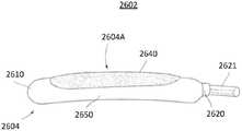
在一些实施例中,可渗透支撑件可由提供可渗透膜和可渗透支撑件两者的功能的材料形成,而不是包括设置在可渗透支撑件上的可渗透膜。例如,图46和图47分别是根据一个实施例的组件2602的侧视图和爆炸图。组件2602包括可渗透支撑件2640、管2621和壳体2604。可渗透支撑件2640可由包括上述实施例的可渗透膜和可渗透支撑件的至少一些特征和/或提供上述实施例的可渗透膜和可渗透支撑件至少一些功能的材料形成。在其他方面,组件2602可在结构和/或功能上与任何上述实施例相同或相似。例如,不可渗透壳体2604可在结构和/或功能上与不可渗透壳体1504,1604,1804,2004,2404和/或2504相同或相似。不可渗透壳体2604可包括贮存器2610、不可渗透背衬2650和出口2620。此外,不可渗透壳体2604可限定长形开口2604A。In some embodiments, rather than including a permeable membrane disposed on a permeable support, a permeable support may be formed of a material that provides the functionality of both a permeable membrane and a permeable support. For example, Figures 46 and 47 are side and exploded views, respectively, of anassembly 2602 according to one embodiment.Assembly 2602 includespermeable support 2640 ,tube 2621 andhousing 2604 . Thepermeable support 2640 may be formed from a material that includes at least some of the features of and/or provides at least some of the functionality of the permeable membranes and permeable supports of the embodiments described above. In other respects,component 2602 can be identical or similar in structure and/or function to any of the above-described embodiments. For example,impermeable shell 2604 may be the same or similar in structure and/or function toimpermeable shells 1504 , 1604 , 1804 , 2004 , 2404 , and/or 2504 . Theimpermeable shell 2604 may include areservoir 2610 , animpermeable backing 2650 and anoutlet 2620 . Additionally, theimpermeable shell 2604 can define anelongated opening 2604A.

如上所述,可渗透支撑件2640可在功能上分别与前述实施例中所述的可渗透膜和/或可渗透支撑件相同或相似。然而,可渗透支撑件2640可由单一材料形成,该单一材料满足前述实施例的可渗透膜和可渗透支撑件的二者材料的功能性要求的和/或包括所述材料的功能性益处。具体地,形成可渗透支撑件2640的材料可具有足够的结构完整性以用作壳体2604的可渗透支撑件,足够的孔隙率和/或渗透性以允许尿液自由地穿过可渗透支撑件2640,和/或足够的蓬松度和弹性以延伸到长形开口2604A或延伸出长形开口2604A。可渗透支撑件2640还可以是足够柔韧的和/或柔性的,使得组件2602可顺应不同形状和/或尺寸的用户,以确保组件2602的有效和牢固的放置。As noted above, thepermeable support 2640 may be functionally the same or similar to the permeable membrane and/or permeable support described in previous embodiments, respectively. However, thepermeable support 2640 may be formed from a single material that meets the functional requirements of and/or includes the functional benefits of the materials of both the permeable membrane and the permeable support of the previous embodiments. In particular, the material forming thepermeable support 2640 may have sufficient structural integrity to serve as a permeable support for thehousing 2604, sufficient porosity and/or permeability to allow urine to pass freely through thepermeable support Member 2640, and/or sufficient loft and elasticity to extend to or out ofelongated opening 2604A.Permeable support 2640 may also be sufficiently pliable and/or flexible such thatassembly 2602 may conform to users of different shapes and/or sizes to ensure effective and secure placement ofassembly 2602 .

此外,形成可渗透支撑件2640的材料可具有外部表面,该外部表面提供与前述实施例的可渗透膜相同的功能。因此,可渗透支撑件2640可以是尿液可渗透的并且可具有芯吸性质。具体地,可渗透膜2640可具有高吸收率和高渗透率,使得尿液可通过其快速吸收和/或运输。可渗透膜2640可以是柔软的和/或最小磨蚀性的,使得其不会刺激用户的皮肤。此外,可渗透膜2640可将流体从尿道口和/或用户的皮肤上吸走,使得用户皮肤的湿气减轻并防止感染。可渗透支撑2640还可以是充分可渗透的和/或具有足够的芯吸能力,以帮助防止尿液泄漏或溢出组件流到例如床上。Additionally, the material forming thepermeable support 2640 may have an exterior surface that provides the same functionality as the permeable membranes of the previous embodiments. Thus, thepermeable support 2640 can be urine permeable and can have wicking properties. In particular, thepermeable membrane 2640 can have a high absorbency and high permeability such that urine can be rapidly absorbed and/or transported therethrough. Thepermeable membrane 2640 may be soft and/or minimally abrasive such that it does not irritate the user's skin. In addition, thepermeable membrane 2640 can draw fluid away from the urethral opening and/or the user's skin, allowing the user's skin to relieve moisture and prevent infection. Thepermeable support 2640 may also be sufficiently permeable and/or have sufficient wicking capacity to help prevent urine from leaking or spilling over the assembly onto, for example, the bed.

例如,如图47和图48中所示,形成可渗透支撑件2640的材料可以是卷曲或折叠成管状形式的柔性片的形式。或者,可渗透支撑件2640可形成为圆筒,使得可渗透支撑件2640具有期望的形状而不用卷曲或折叠。可渗透支撑件2640可由例如聚酯、回收聚酯羊毛和/或尼龙针织网制成。可渗透支撑件2640可固定在中空的壳体(例如,图46和47中所示的壳体2604)内,通过将可渗透支撑件2640经由壳体的长形开口(例如壳体2604的长形开口2604A)插入壳体内。在一些实施方式中,可渗透支撑件2640可以通过使用任何合适的手段(例如,使用粘合剂、胶和/或带)附接在诸如壳体2604的壳体上。For example, as shown in Figures 47 and 48, the material forming thepermeable support 2640 may be in the form of a flexible sheet rolled or folded into a tubular form. Alternatively, thepermeable support 2640 may be formed as a cylinder such that thepermeable support 2640 has a desired shape without crimping or folding. Thepermeable support 2640 may be made of polyester, recycled polyester wool, and/or nylon knit mesh, for example. Thepermeable support 2640 can be secured within a hollow housing (eg,housing 2604 shown in FIGS. 46 and 47 ) by passing thepermeable support 2640 through an elongated opening of the housing (eg, the shapedopening 2604A) into the housing. In some embodiments,permeable support 2640 can be attached to a housing such ashousing 2604 by using any suitable means (eg, using adhesives, glue, and/or tape).

在使用中,一旦插入并定位在不可渗透背衬2650上,组件2602可以相对于用户定位,使得可渗透支撑件2640的表面接触用户的尿道口。尿液可穿过可渗透支撑件2640抽出,使得尿液收集在贮存器2610中。然后可使用例如外部真空源(未示出)从贮存器2610通过管2621并穿过出口2620抽取尿液。形成可渗透支撑件2640的材料可以是可压缩的。该材料还可具有像海绵一样的性质,使得材料在润湿时可维持形状,从而在排尿活动期间通过经由长形开口2604A在壳体2604外部的可渗透支撑件2640的轻微突出而维持与用户的接触。尽管出于解释目的在图46和图47中可渗透支撑件2640与壳体2604一起示出,但可渗透支撑件2640可与本文所示或所述的任何组件或壳体结合使用,例如图9的组件802,图18的组件,图27的壳体1504,图32的壳体1604,图34-35的壳体1804,图37-38的组件1702,图40的壳体2004,图44A的壳体2404,和/或图45中的壳体2504。In use, once inserted and positioned on theimpermeable backing 2650, theassembly 2602 can be positioned relative to the user such that the surface of thepermeable support 2640 contacts the user's urethral opening. Urine may be drawn throughpermeable support 2640 such that the urine collects inreservoir 2610 . Urine may then be drawn fromreservoir 2610 throughtube 2621 and throughoutlet 2620 using, for example, an external vacuum source (not shown). The material formingpermeable support 2640 may be compressible. The material may also have sponge-like properties such that the material retains its shape when wetted, thereby maintaining contact with the user during urination activities through the slight protrusion of thepermeable support 2640 outside thehousing 2604 through theelongated opening 2604A. s contact. Althoughpermeable support 2640 is shown withhousing 2604 in FIGS.Assembly 802 of Figure 9, assembly of Figure 18,housing 1504 of Figure 27,housing 1604 of Figure 32,housing 1804 of Figures 34-35,assembly 1702 of Figures 37-38,housing 2004 of Figure 40,Figure 44A Housing 2404, and/orhousing 2504 in FIG. 45 .

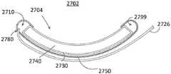
在一些实施例中,组件可包括出口管,该出口管部分地插入贮存器中并且远离组件延伸,而不包括参考图45中的组件2500所展示和描述的出口管。例如,图49A是组件2702的纵向横截面示图。组件2702可包括壳体2704、可渗透支撑件2740和可渗透膜2730。组件2702可在结构和/或功能上本文所述的任何组件类似,例如,参考图1所展示和描述的组件102,参考图35所展示和描述的组件1802,和/或参考图46所展示和描述的组件2602。具体地,壳体2704可在结构和/或功能上与本文所述的任何壳体类似,例如,参考图27和图28所展示和描述的壳体1504,参考图34所展示和描述的壳体1804,参考图40所展示和描述的壳体2004,参考图44A所展示和描述的壳体2404和/或参考图45所展示和描述的壳体2504。壳体2704可包括例如不可渗透背衬2750,贮存器2710,与贮存器2710相对的封闭端2799,以及由不可渗透背衬2750和/或贮存器2710限定的开口2780。壳体2704可制成为是或不是预弯曲形式。例如,在一些实施方式中,壳体2704可预弯曲,使得壳体2704是凹形的或凸形的。尽管图中示出为包括单独的可渗透膜2730和可渗透支撑件2740,但是在一些实施例中,组件2702可包括由一材料制成的可渗透支撑件2740,该材料使得该可渗透支撑件2740可以包括本文所述的任何可渗透膜的一些或全部功能。在这些实施例中,组件2702可仅包括可渗透支撑件,而不包括设置在可渗透支撑件上的单独的可渗透膜。In some embodiments, the assembly may include an outlet tube that is partially inserted into the reservoir and extends away from the assembly, other than the outlet tube shown and described with reference toassembly 2500 in FIG. 45 . For example, FIG. 49A is a longitudinal cross-sectional view ofassembly 2702 .Assembly 2702 may includehousing 2704 ,permeable support 2740 andpermeable membrane 2730 .Component 2702 may be similar in structure and/or function to any component described herein, for example,component 102 shown and described with reference to FIG. 1 ,component 1802 shown and described with reference to FIG. 35 , and/or shown with reference to FIG. and describedcomponent 2602. In particular,housing 2704 may be similar in structure and/or function to any housing described herein, for example,housing 1504 shown and described with reference to FIGS. 27 and 28 , housing shown and described with reference to FIG. 34Body 1804,housing 2004 shown and described with reference to FIG. 40 ,housing 2404 shown and described with reference to FIG. 44A and/orhousing 2504 shown and described with reference to FIG. 45 .Housing 2704 can include, for example,impermeable backing 2750 ,reservoir 2710 , closedend 2799 oppositereservoir 2710 , andopening 2780 defined byimpermeable backing 2750 and/orreservoir 2710 .Housing 2704 may or may not be made in a pre-bent form. For example, in some embodiments, thehousing 2704 can be pre-bent such that thehousing 2704 is concave or convex. Although shown as comprising a separatepermeable membrane 2730 andpermeable support 2740, in someembodiments assembly 2702 may comprise apermeable support 2740 made of a material such that thepermeable support Member 2740 may include some or all of the functionality of any of the permeable membranes described herein. In these embodiments,assembly 2702 may include only a permeable support without a separate permeable membrane disposed on the permeable support.

组件2702可包括出口管2726,出口管2726可穿过开口2780插入壳体2704中,使得管2726被插入的开口端可设置在贮存器2710内。在这种布置中,管2726的内腔可与贮存器流体连通。在图49B的横截面图中示出了安装有出口管2726的示例性壳体2704。出口管2726可由柔性或刚性材料制成。如图49B和图49C中的沿线49C-49C剖切的横截面视图所示,出口管2726可沿着壳体2704的外侧并远离壳体2704延伸。出口管2726可具有任何合适的长度,使得出口管2726适于从贮存器2710中取出流体。出口管2726可通过任何防漏连接机构固定到壳体2704上,例如通过使用压力穿过开口2780插入、或者利用管2726和壳体2704的静摩擦属性。在一些实施方式中,由于出口管2726的贮存器端的直径比开口2880A大,出口管2726可固定到壳体2704上。在一些实施方式中,出口管2726可通过例如防漏紧固机构(例如,粘合剂和/或带)固定到壳体2704上。在一些实施方式中,出口管2726可直接与外部接收器(例如,外部接收器160)连接,使得收集在贮存器中的尿液可通过出口管2726输送到外部接收器。在一些实施方式中,出口管2726可通过连接到出口管2726的另一管(未图示)与外部接收器连接。在一些实施方式中,真空源可用于帮助通过出口管2726从贮存器2710抽取流体。Assembly 2702 can includeoutlet tube 2726 that can be inserted intohousing 2704 throughopening 2780 such that the open end into whichtube 2726 is inserted can be disposed withinreservoir 2710 . In such an arrangement, the lumen oftube 2726 may be in fluid communication with the reservoir. Anexemplary housing 2704 with anoutlet tube 2726 installed is shown in cross-sectional view in FIG. 49B .Outlet tube 2726 may be made of flexible or rigid material. As shown in the cross-sectional views taken alongline 49C-49C in FIGS. 49B and 49C , theoutlet tube 2726 can extend along the outside of thehousing 2704 and away from thehousing 2704 .Outlet tube 2726 may have any suitable length such thatoutlet tube 2726 is adapted to remove fluid fromreservoir 2710 .Outlet tube 2726 may be secured tohousing 2704 by any leak-proof connection mechanism, such as by using pressure to insert throughopening 2780 , or utilizing the stiction properties oftube 2726 andhousing 2704 . In some embodiments, theoutlet tube 2726 can be secured to thehousing 2704 due to the larger diameter of the reservoir end of theoutlet tube 2726 than theopening 2880A. In some embodiments, theoutlet tube 2726 can be secured to thehousing 2704 by, for example, a leak-proof fastening mechanism (eg, adhesive and/or tape). In some embodiments,outlet tube 2726 can be directly connected to an external receiver (eg, external receiver 160 ), such that urine collected in the reservoir can be delivered throughoutlet tube 2726 to the external receiver. In some embodiments, theoutlet tube 2726 can be connected to an external receiver through another tube (not shown) connected to theoutlet tube 2726 . In some embodiments, a vacuum source may be used to assist in drawing fluid from thereservoir 2710 through theoutlet tube 2726 .

虽然图49A示出了设置在贮存器2710中或贮存器附近的开口2780,但在其他实施例中,在结构和/或功能上与开口2780类似的一个或多个开口可设置在沿着不可渗透背衬2750的长度以及横向地沿着不可渗透背衬2750的宽度的一个或多个其他位置处,使得诸如出口管2726的管可插入并固定在壳体2704的一个或多个开口的每一个中。例如,如图50A所示,组件2802包括第一管2826A和第二管2826B。组件2802可在结构和/或功能上与本文所述的任何组件相似。例如,组件2802可包括限定长形开口2804A的壳体2804,不可渗透背衬2850,贮存器2810和与贮存器端相对的封闭端2899。图51示出了组件2802的浅角度透视图,组件2802具有与壳体2804连接的第一管2826A和第二管2826B。如图50A和51所示,壳体2804可限定第一开口2880A和第二开口2880B(图51中示出),该第一开口和第二开口被限定在不可渗透背衬2850上,第一管2826A和第二管2826B可分别穿过第一开口2880A和第二开口2880B插入。例如,如图50A中的虚线所示,管2826A的贮存器端可穿过开口2880A插入到贮存器2810中。第一管2826A和第二管2826B中的每一个设置在壳体内的部分可具有任何合适的长度,其允许适当地提取收集在贮存器中的流体而不会对第一管2826A和第二管2826B的开口顶端造成任何阻塞。第一管2826A和第二管2826B的开口顶端可设置在贮存器2810内,使得在例如真空吸力或重力的帮助下流体可在使用期间从贮存器2810流出而不被壳体2804阻塞或干扰。Although FIG. 49A illustrates opening 2780 disposed in or nearreservoir 2710, in other embodiments, one or more openings similar in structure and/or function to opening 2780 may be disposed along an otherwise inaccessible The length of thepermeable backing 2750 and at one or more other locations laterally along the width of theimpermeable backing 2750, such that a tube, such as anoutlet tube 2726, can be inserted and secured in each of the one or more openings of thehousing 2704. in one. For example, as shown in Figure 50A,assembly 2802 includes afirst tube 2826A and asecond tube 2826B.Component 2802 may be similar in structure and/or function to any of the components described herein. For example,assembly 2802 can includehousing 2804 definingelongated opening 2804A,impermeable backing 2850,reservoir 2810, andclosed end 2899 opposite the reservoir end. FIG. 51 shows a shallow perspective view ofassembly 2802 havingfirst tube 2826A andsecond tube 2826B connected tohousing 2804 . As shown in FIGS. 50A and 51 , thehousing 2804 can define afirst opening 2880A and asecond opening 2880B (shown in FIG. 51 ), which are defined on theimpermeable backing 2850, the first Thetube 2826A and thesecond tube 2826B can be inserted through thefirst opening 2880A and thesecond opening 2880B, respectively. For example, the reservoir end oftube 2826A may be inserted intoreservoir 2810 throughopening 2880A, as shown in phantom in FIG. 50A. The portion of each of thefirst tube 2826A and thesecond tube 2826B disposed within the housing may have any suitable length that allows proper extraction of the fluid collected in the reservoir without causing damage to thefirst tube 2826A and the second tube. The open top of the 2826B causes any obstruction. The open top ends of thefirst tube 2826A and thesecond tube 2826B may be disposed within thereservoir 2810 such that fluid may flow from thereservoir 2810 during use without being obstructed or disturbed by thehousing 2804 with the aid of, for example, vacuum suction or gravity.

在一些实施方式中,两个开口2880A和2880B可沿着壳体2804的长度和宽度设置在任何合适的位置,使得在第一管2826A和第二管2826B的贮存器端之间可以存在足够的空间间隔以便在使用组件2802期间最大化地和有效地取出收集在贮存器2810中的尿液。此外,两个开口2880A和2880B可以定位成使得可确保第一管2826A、第二管2826B与壳体之间的适当连接。In some embodiments, the twoopenings 2880A and 2880B may be positioned at any suitable location along the length and width of thehousing 2804 such that there may be sufficient Spaced apart to maximize and efficiently remove urine collected inreservoir 2810 during use ofassembly 2802 . Additionally, the twoopenings 2880A and 2880B can be positioned such that proper connection between thefirst tube 2826A, thesecond tube 2826B and the housing can be ensured.

组件2802可成型为使得出口管2826A和出口管2826B沿着如图50B所示的壳体2804的外侧延伸,该图是沿图50A中的线50B-50B剖切的横截面视图。组件2802可包括可渗透支撑件2840和可渗透膜2830,并且可定位为成使得可渗透膜2830的一部分穿过长形开口2804A延伸并抵靠或靠近用户的尿道口。在一些实施方式中,管2826A和管2826B可直接与外部接收器(例如,外部接收器160)连接,使得收集在贮存器中的尿液可通过管2826A和管2826B运输到外部接收器。在一些实施方式中,通过与管2826A和管2826B连接的外部管2822(如图51所示),管2826A和管2826B可与外部接收器连接。管2826A和管2826B可使用任何允许防漏连接的连接机构连接到外部管2822,所述连接机构例如管配件、粘合剂或带。在一些实施方式中,真空源可用于帮助通过管2826A和管2826B从贮存器2810抽取流体。管2826A和管2826B、外部管2822和外壳2804的定位、结构和材料可设置为使得组件2802允许流体自由流动,从用户的尿道口出发,流过可渗透膜2830,流过可渗透支撑件2840,进入贮存器2810,流过开口2880A和开口2880B并且流过管2826A和管2826,而不会阻塞管2826A和管2826的开放贮存器端。此外,组件2802可承受由于施加真空吸力以抽出收集在贮存器2810中的流体(例如,尿液)而引起的压力差。同时组件2802还可以是足够柔韧的和/或柔性的,以顺应不同用户的尺寸和形状,以确保所排出的尿液的有效转移。Assembly 2802 may be shaped such thatoutlet tube 2826A andoutlet tube 2826B extend along the outside ofhousing 2804 as shown in Figure 50B, which is a cross-sectional view taken alongline 50B-50B in Figure 50A.Assembly 2802 can includepermeable support 2840 andpermeable membrane 2830 and can be positioned such that a portion ofpermeable membrane 2830 extends throughelongated opening 2804A and against or near the user's urethral opening. In some embodiments,tube 2826A andtube 2826B can be directly connected to an external receiver (eg, external receiver 160 ), such that urine collected in the reservoir can be transported to the external receiver throughtube 2826A andtube 2826B. In some embodiments,tube 2826A andtube 2826B can be connected to an external receiver via an external tube 2822 (as shown in FIG. 51 ) that is connected totube 2826A andtube 2826B.Tube 2826A andtube 2826B may be connected toouter tube 2822 using any connection mechanism that allows for a leak-proof connection, such as pipe fittings, adhesive, or tape. In some embodiments, a vacuum source may be used to assist in drawing fluid fromreservoir 2810 throughtubes 2826A and 2826B. The positioning, construction and materials oftubes 2826A and 2826B,outer tube 2822 andhousing 2804 can be arranged such thatassembly 2802 allows fluid to flow freely from the user's urethral opening, throughpermeable membrane 2830, and throughpermeable support 2840 , intoreservoir 2810, flow throughopening 2880A andopening 2880B and throughtube 2826A and tube 2826 without clogging the open reservoir ends oftube 2826A and tube 2826. Additionally,assembly 2802 can withstand pressure differentials due to the application of vacuum suction to draw out fluid (eg, urine) collected inreservoir 2810 . Whilstassembly 2802 may also be sufficiently pliable and/or flexible to conform to the size and shape of different users to ensure effective transfer of discharged urine.

尽管如图50B所示,组件2802显示为包括可渗透支撑件2840(由点图案表示)和可渗透膜2830(由十字形图案表示),但是在其他实施例中,组件可以包括可渗透支撑件2840,可渗透支撑件2840由使得其起到可渗透支撑件和可渗透膜的二者功能的材料制成。这种可渗透支撑件2840可在结构和/或功能上与组件2602中的可渗透支撑件2640类似。例如,可渗透支撑件2840可具有外部表面,该外部表面具有芯吸性质、高吸收率和/或高渗透率,使得尿液可通过其被快速吸收和/或运输。另外,可渗透支撑件2840可以是柔软的和/或最小磨蚀性的,使得可渗透支撑件2840的外表面不会刺激用户的皮肤。可渗透支撑件2840还可由能将流体从尿道口和/或用户的皮肤上吸走使得用户皮肤的湿气减轻并防止感染的材料制成。Although, as shown in FIG. 50B ,assembly 2802 is shown comprising a permeable support 2840 (represented by a pattern of dots) and a permeable membrane 2830 (represented by a pattern of crosses), in other embodiments the assembly may comprise apermeable support 2840, Thepermeable support 2840 is made of a material such that it functions as both a permeable support and a permeable membrane. Suchpermeable support 2840 may be similar in structure and/or function topermeable support 2640 inassembly 2602 . For example,permeable support 2840 may have an exterior surface having wicking properties, high absorbency, and/or high permeability such that urine may be rapidly absorbed and/or transported therethrough. Additionally, thepermeable support 2840 can be soft and/or minimally abrasive such that the outer surface of thepermeable support 2840 does not irritate the user's skin. Thepermeable support 2840 may also be made of a material that draws fluid away from the urethral opening and/or the user's skin so that the user's skin is relieved of moisture and infection is prevented.

虽然上文已经描述了系统、方法和设备的各种实施例,但是应当该理解,它们仅作示例呈现而不起限制作用。在上述方法和步骤表示以一定顺序发生的某些事件的情况下,受益于本公开的本领域普通技术人员将认识到可以修改某些步骤的顺序并且这些修改是根据本发明的变化做出的。此外,在可能的情况下某些步骤可以以并行的方式中同时执行,以及如上述顺序执行。但是应当理解,已经特别示出和描述了实施例可以在形式和细节上做出各种改变。While various embodiments of systems, methods, and devices have been described above, it should be understood that they have been presented by way of example only, and not limitation. Where the methods and steps described above represent certain events occurring in a certain order, those of ordinary skill in the art having the benefit of this disclosure will recognize that the order of certain steps may be modified and that such modifications are made in accordance with variations of the invention . Furthermore, certain steps may be performed simultaneously in a parallel fashion where possible, as well as sequentially as described above. It is to be understood, however, that what has been particularly shown and described embodiments may make various changes in form and detail.

例如,尽管已经将各种实施例描述为具有特定特征和/或部件的组合,但是其他实施例可能具有本文描述的任何实施例的任何特征和/或部件的任何组合或子组合。此外,各种部件的具体配置也可改变。例如,各种部件的尺寸和具体形状可与实施例所示的不同,但仍提供如本文所述的功能。For example, although various embodiments have been described as having particular combinations of features and/or components, other embodiments are possible having any combination or subcombination of any of the features and/or components of any of the embodiments described herein. In addition, the specific configuration of the various components may also vary. For example, the size and specific shape of the various components can be varied from that shown in the embodiments and still provide the functionality as described herein.

Claims (23)

Translated fromChinese
1.一种尿液收集系统,包括:1. A urine collection system comprising:尿液收集装置,该尿液收集装置包括:A urine collection device comprising:长形的流体不可渗透构件,具有:第一末端区域和远离所述第一末端区域的第二末端区域,在第一末端区域和第二末端区域之间延伸的背部区域,与所述背部区域间隔开并且远离所述背部区域的至少一部分的前部区域,所述流体不可渗透构件至少部分地限定一内部区域和至少部分地限定位于第一末端区域和第二末端区域之间且与所述流体不可渗透构件的背部区域相对的所述前部区域上的纵向长形开口;An elongated fluid-impermeable member having a first end region and a second end region remote from the first end region, a back region extending between the first end region and the second end region, and the back region Spaced apart from and away from at least a portion of the front region of the back region, the fluid impermeable member at least partially defines an interior region and at least partially defines a a longitudinally elongated opening in said front region opposite the back region of the fluid-impermeable member;流体可渗透主体,至少部分地设置在所述流体不可渗透构件的所述内部区域内,且所述流体可渗透主体的一部分至少部分地延伸跨过所述长形开口;以及a fluid permeable body at least partially disposed within the interior region of the fluid impermeable member, and a portion of the fluid permeable body extends at least partially across the elongated opening; and具有通道开口的通道,其中所述通道开口与内部区域流体连通,且设置为靠近所述流体不可渗透构件的第二末端区域和背部区域。A channel having a channel opening, wherein the channel opening is in fluid communication with the interior region and is disposed proximate to the second end region and the back region of the fluid impermeable member.2.根据权利要求1所述的尿液收集系统,其特征在于:2. The urine collection system of claim 1, wherein:所述流体不可渗透构件的背部区域包括:The back region of the fluid impermeable member comprises:不可渗透背衬,其至少部分地限定所述内部区域,并从所述通道开口至少部分地延伸到所述第一末端区域;和an impermeable backing at least partially bounding the interior region and extending at least partially from the passage opening to the first end region; and不可渗透的外部壁,其从所述通道开口至少部分地向着所述第一末端区域延伸,使得所述不可渗透背衬在所述不可渗透的外部壁和所述流体可渗透主体之间;an impermeable outer wall extending at least partially from the passage opening towards the first end region such that the impermeable backing is between the impermeable outer wall and the fluid permeable body;所述通道开口延伸通过所述不可渗透背衬;以及the channel opening extends through the impermeable backing; and所述通道从所述通道开口沿着所述背部区域向着所述第一末端区域延伸,且所述通道由所述不可渗透背衬和所述不可渗透的外部壁所限定。The channel extends from the channel opening along the back region towards the first end region, and the channel is defined by the impermeable backing and the impermeable outer wall.3.根据权利要求2所述的尿液收集系统,还包括管,该管固定至所述尿液收集装置,靠近所述流体不可渗透构件的第一末端区域并与所述通道流体连通。3. The urine collection system of claim 2, further comprising a tube secured to the urine collection device proximate the first end region of the fluid impermeable member and in fluid communication with the channel.4.根据权利要求1所述的尿液收集系统,其特征在于,所述流体不可渗透构件包括两个长形边缘,该两个长形边缘从所述前部区域向内间隔开,使得该两个长形边缘被定位在所述前部区域和所述背部区域之间,该两个长形边缘至少部分地限定所述长形开口。4. The urine collection system of claim 1 , wherein the fluid impermeable member includes two elongated edges spaced inwardly from the front region such that the Two elongated edges are positioned between the front region and the back region, the two elongated edges at least partially defining the elongated opening.5.根据权利要求4所述的尿液收集系统,其特征在于,所述流体可渗透主体包括流体可渗透支撑件和流体可渗透膜,该流体可渗透膜设置在所述流体可渗透支撑件的至少一部分上并覆盖所述流体可渗透支撑件的至少一部分,使得所述流体可渗透膜被支撑在所述流体可渗透支撑件上并且所述流体可渗透膜的至少一部分延伸跨过所述流体不可渗透构件的所述长形开口的至少一部分。5. The urine collection system of claim 4, wherein said fluid permeable body comprises a fluid permeable support and a fluid permeable membrane disposed on said fluid permeable support and covering at least a portion of the fluid permeable support such that the fluid permeable membrane is supported on the fluid permeable support and at least a portion of the fluid permeable membrane extends across the At least a portion of said elongated opening of the fluid impermeable member.6.根据权利要求5所述的尿液收集系统,其特征在于,所述流体可渗透膜配置为将流体从用户的皮肤处吸走,并且所述流体可渗透支撑件包括海绵状特性。6. The urine collection system of claim 5, wherein the fluid permeable membrane is configured to draw fluid away from the user's skin, and the fluid permeable support includes spongy properties.7.根据权利要求4所述的尿液收集系统,还包括管,该管固定至所述尿液收集装置并且至少部分地限定所述通道,其中,所述管从所述第二末端区域向着所述第一末端区域延伸,至少靠近所述流体不可渗透构件的所述背部区域。7. The urine collection system of claim 4, further comprising a tube secured to the urine collection device and at least partially defining the passageway, wherein the tube extends from the second end region toward The first end region extends at least close to the back region of the fluid impermeable member.8.根据权利要求4所述的尿液收集系统,还包括管,该管固定至所述尿液收集装置,靠近所述流体不可渗透构件的第二末端区域,并至少部分地限定所述开口,其中,所述管的至少一部分向外远离所述流体不可渗透构件的背部区域地延伸。8. The urine collection system of claim 4, further comprising a tube secured to the urine collection device proximate to the second end region of the fluid impermeable member and at least partially defining the opening , wherein at least a portion of the tube extends outwardly away from the back region of the fluid-impermeable member.9.根据权利要求4所述的尿液收集系统,还包括:9. The urine collection system of claim 4, further comprising:出口管,该出口管从所述背部区域至少靠近所述流体不可渗透构件的第二末端区域地向外突出,所述出口管限定所述通道开口,且部分地限定所述通道;和an outlet tube projecting outwardly from the back region at least proximate a second end region of the fluid-impermeable member, the outlet tube defining the channel opening and partially defining the channel; and外部管,该外部管固定至所述出口管并且与所述通道开口流体连通,所述外部管部分地限定所述通道。An outer tube secured to the outlet tube and in fluid communication with the channel opening, the outer tube partially defining the channel.10.根据权利要求4所述的尿液收集系统,其特征在于:10. The urine collection system of claim 4, wherein:所述尿液收集装置还包括流体贮存器,该流体贮存器在所述流体不可渗透构件的第二末端区域处的所述内部区域中;和The urine collection device further comprises a fluid reservoir in the interior region at the second end region of the fluid impermeable member; and所述通道开口设置为靠近所述贮存器,且所述通道开口与所述贮存器之间不存在所述流体可渗透主体。The passage opening is disposed proximate to the reservoir without the fluid permeable body between the passage opening and the reservoir.11.根据权利要求1所述的尿液收集系统,其特征在于,所述尿液收集装置配置为维持弯曲形状,其中,所述长形开口设置在所述弯曲的内侧。11. The urine collection system of claim 1, wherein the urine collection device is configured to maintain a curved shape, wherein the elongated opening is disposed on an inner side of the curve.12.根据权利要求1所述的尿液收集系统,还包括:12. The urine collection system of claim 1, further comprising:容器,其与所述尿液收集装置流体连通;和a container in fluid communication with the urine collection device; and泵,其配置为至少部分地提供压力差,以将尿液吸入所述流体可渗透主体中和吸入所述通道中,以将尿液引导到所述容器中。A pump configured to at least partially provide a pressure differential to draw urine into the fluid permeable body and into the passageway to direct urine into the container.13.根据权利要求12所述的尿液收集系统,还包括固定或可固定到容器并具有安装在其上的泵的组件,该组件具有固定或可固定到其上的管,该管与所述通道流体连通。13. The urine collection system of claim 12, further comprising an assembly fixed or fixable to the container and having a pump mounted thereon, the component having a tube fixed or fixable thereto, the tube being connected to the The channels are in fluid communication.14.根据权利要求13所述的尿液收集系统,其特征在于,所述组件还包括固定至其上并延伸到所述容器中的竖向管道,所述竖向管道与固定或可固定到所述组件上的所述管流体连通。14. The urine collection system of claim 13, wherein said assembly further comprises a vertical conduit secured thereto and extending into said container, said vertical conduit being fixed or fixable to The tubes on the assembly are in fluid communication.15.一种尿液收集系统,包括:15. A urine collection system comprising:容器;container;固定或可固定到所述容器的组件,该组件包括安装到其上的泵;an assembly fixed or fixable to said container, the assembly including a pump mounted thereto;尿液收集装置,其包括:A urine collection device comprising:长形的流体不可渗透构件,其具有第一末端区域和远离所述第一末端区域的第二末端区域,在第一末端区域和第二末端区域之间延伸的背部区域,与所述背部区域间隔开并且远离所述背部区域的至少一部分的前部区域,所述流体不可渗透构件至少部分地限定内部区域和纵向长形开口,所述纵向长形开口位于在所述第一末端区域和所述第二末端区域之间并与所述流体不可渗透构件的所述背部区域相对的所述前部区域上;An elongate fluid impermeable member having a first end region and a second end region remote from the first end region, a back region extending between the first end region and the second end region, and the back region Spaced apart from and away from at least a portion of the front region of the back region, the fluid impermeable member at least partially defines an interior region and a longitudinally elongated opening located between the first end region and the on said front region between said second end regions and opposite said back region of said fluid impermeable member;流体可渗透主体,其至少部分地设置在所述流体不可渗透构件的所述内部区域内,且所述流体可渗透主体的一部分至少部分地延伸跨过所述长形开口;以及a fluid permeable body at least partially disposed within the interior region of the fluid impermeable member, and a portion of the fluid permeable body extends at least partially across the elongated opening; and通道,其具有通道开口,该通道开口设置为靠近所述流体不可渗透构件的所述第二末端区域和所述背部区域,其中,所述泵配置为至少部分地提供压力差,以将尿液吸入所述流体可渗透主体中和吸入所述通道中,以将尿液引导到所述容器中。a channel having a channel opening disposed proximate the second end region and the back region of the fluid impermeable member, wherein the pump is configured to at least partially provide a pressure differential to push urine Drawing into the fluid permeable body and into the channel directs urine into the container.16.根据权利要求15所述的尿液收集系统,其特征在于,所述组件还包括固定到其上并延伸到所述容器中的竖向管道,该竖向管道与所述通道流体连通。16. The urine collection system of claim 15, wherein the assembly further comprises a vertical conduit secured thereto and extending into the container, the vertical conduit being in fluid communication with the channel.17.根据权利要求15所述的尿液收集系统,其特征在于,17. The urine collection system of claim 15, wherein,所述流体不可渗透构件的所述背部区域包括:The back region of the fluid impermeable member comprises:不可渗透背衬,其至少部分地限定所述内部区域,并从所述通道开口至少部分地延伸到所述第一末端区域;和an impermeable backing at least partially bounding the interior region and extending at least partially from the passage opening to the first end region; and不可渗透的外部壁,其从所述通道开口至少部分地向着所述第一末端区域延伸,使得所述不可渗透背衬在所述不可渗透的外部壁和所述流体可渗透主体之间;an impermeable outer wall extending at least partially from the passage opening towards the first end region such that the impermeable backing is between the impermeable outer wall and the fluid permeable body;所述通道开口延伸通过所述不可渗透背衬;以及the channel opening extends through the impermeable backing; and所述通道从所述通道开口沿着所述背部区域向着所述第一末端区域延伸,且所述通道由所述不可渗透背衬和所述不可渗透的外部壁所限定。The channel extends from the channel opening along the back region towards the first end region, and the channel is defined by the impermeable backing and the impermeable outer wall.18.根据权利要求17所述的尿液收集系统,还包括管,该管靠近所述流体不可渗透构件的第一末端区域并延伸至所述容器地固定到所述尿液收集装置,所述管与所述通道流体连通。18. The urine collection system of claim 17, further comprising a tube fixed to the urine collection device proximate to the first end region of the fluid impermeable member and extending to the container, the A tube is in fluid communication with the channel.19.根据权利要求15所述的尿液收集系统,其特征在于,所述流体不可渗透构件包括两个长形边缘,该两个长形边缘从所述前部区域向内间隔开,使得该两个长形边缘被定位在所述前部区域和所述背部区域之间,该两个长形边缘至少部分地限定所述长形开口。19. The urine collection system of claim 15, wherein the fluid impermeable member includes two elongated edges spaced inwardly from the front region such that the Two elongated edges are positioned between the front region and the back region, the two elongated edges at least partially defining the elongated opening.20.根据权利要求19所述的尿液收集系统,还包括管,该管固定至所述尿液收集装置并且至少部分地限定所述通道,其中,所述管至少靠近所述流体不可渗透构件的所述背部区域地从所述第二末端区域向着所述第一末端区域延伸。20. The urine collection system of claim 19, further comprising a tube secured to the urine collection device and at least partially defining the channel, wherein the tube is at least proximate to the fluid impermeable member The back region extends from the second end region toward the first end region.21.根据权利要求19所述的尿液收集系统,还包括管,该管靠近所述流体不可渗透构件的第二末端区域并至少部分地限定所述通道地固定至所述尿液收集装置,其中,所述管的至少一部分远离所述流体不可渗透构件的所述背部区域地向外延伸。21. The urine collection system of claim 19, further comprising a tube secured to the urine collection device proximate to the second end region of the fluid impermeable member and at least partially defining the passageway, Wherein at least a portion of the tube extends outwardly away from the back region of the fluid impermeable member.22.根据权利要求19所述的尿液收集系统,还包括:22. The urine collection system of claim 19, further comprising:出口管,该出口管至少靠近所述流体不可渗透构件的所述第二末端区域地从所述背部区域向外突出,所述出口管限定所述通道开口并且部分地限定所述通道;和an outlet tube protruding outwardly from said back region at least proximate said second end region of said fluid-impermeable member, said outlet tube defining said channel opening and partially defining said channel; and外部管,该外部管固定至所述出口管并与所述通道开口流体连通,所述外部管部分地限定所述通道。An outer tube secured to the outlet tube and in fluid communication with the channel opening, the outer tube partially defining the channel.23.根据权利要求19所述的尿液收集系统,其特征在于:23. The urine collection system of claim 19, wherein:所述尿液收集装置还包括流体贮存器,该流体贮存器在所述流体不可渗透构件的第二末端区域处的所述内部区域中;和The urine collection device further comprises a fluid reservoir in the interior region at the second end region of the fluid impermeable member; and所述通道开口设置为靠近所述贮存器,且所述通道开口和所述贮存器之间不存在所述流体可渗透主体。The passage opening is disposed proximate to the reservoir without the fluid permeable body between the passage opening and the reservoir.
CN202210964260.5A2016-06-022017-06-02 Apparatus and method for receiving excreted urinePendingCN115252264A (en)

Applications Claiming Priority (14)

Application NumberPriority DateFiling DateTitle
US15/171,9682016-06-02
US15/171,968US10952889B2 (en)2016-06-022016-06-02Using wicking material to collect liquid for transport
PCT/US2016/049274WO2017209779A1 (en)2016-06-022016-08-29Apparatus and methods for receiving discharged urine
USPCT/US2016/0492742016-08-29
US15/260,103US10390989B2 (en)2014-03-192016-09-08Apparatus and methods for receiving discharged urine
US15/260,1032016-09-08
US201662414963P2016-10-312016-10-31
US62/414,9632016-10-31
US201762485578P2017-04-142017-04-14
US62/485,5782017-04-14
US15/611,5872017-06-01
US15/611,587US10226376B2 (en)2014-03-192017-06-01Apparatus and methods for receiving discharged urine
CN201780048996.5ACN110381883A (en)2016-06-022017-06-02Device and method for receiving discharged urine
PCT/US2017/035625WO2017210524A1 (en)2016-06-022017-06-02Apparatus and methods for receiving discharged urine

Related Parent Applications (1)

Application NumberTitlePriority DateFiling Date
CN201780048996.5ADivisionCN110381883A (en)2016-06-022017-06-02Device and method for receiving discharged urine

Publications (1)

Publication NumberPublication Date
CN115252264Atrue CN115252264A (en)2022-11-01

Family

ID=60477975

Family Applications (5)

Application NumberTitlePriority DateFiling Date
CN202210964260.5APendingCN115252264A (en)2016-06-022017-06-02 Apparatus and method for receiving excreted urine
CN202210964267.7APendingCN115252265A (en)2016-06-022017-06-02 Apparatus and method for receiving excreted urine
CN201780048996.5APendingCN110381883A (en)2016-06-022017-06-02Device and method for receiving discharged urine
CN202210964271.3APendingCN115252266A (en)2016-06-022017-06-02 Apparatus and method for receiving excreted urine
CN202410819933.7APendingCN118902722A (en)2016-06-022017-06-02Device and method for receiving discharged urine

Family Applications After (4)

Application NumberTitlePriority DateFiling Date
CN202210964267.7APendingCN115252265A (en)2016-06-022017-06-02 Apparatus and method for receiving excreted urine
CN201780048996.5APendingCN110381883A (en)2016-06-022017-06-02Device and method for receiving discharged urine
CN202210964271.3APendingCN115252266A (en)2016-06-022017-06-02 Apparatus and method for receiving excreted urine
CN202410819933.7APendingCN118902722A (en)2016-06-022017-06-02Device and method for receiving discharged urine

Country Status (7)

CountryLink
EP (3)EP4623874A2 (en)
JP (2)JP6759456B2 (en)
CN (5)CN115252264A (en)
AU (1)AU2017275649B2 (en)
CA (1)CA3027298C (en)
ES (1)ES2946187T3 (en)
WO (1)WO2017210524A1 (en)

Families Citing this family (54)

* Cited by examiner, † Cited by third party
Publication numberPriority datePublication dateAssigneeTitle
US11806266B2 (en)2014-03-192023-11-07Purewick CorporationApparatus and methods for receiving discharged urine
US10952889B2 (en)2016-06-022021-03-23Purewick CorporationUsing wicking material to collect liquid for transport
US11090183B2 (en)2014-11-252021-08-17Purewick CorporationContainer for collecting liquid for transport
US11376152B2 (en)2014-03-192022-07-05Purewick CorporationApparatus and methods for receiving discharged urine
US10226376B2 (en)2014-03-192019-03-12Purewick CorporationApparatus and methods for receiving discharged urine
US10390989B2 (en)2014-03-192019-08-27Purewick CorporationApparatus and methods for receiving discharged urine
USD928946S1 (en)2016-06-022021-08-24Purewick CorporationUrine receiving apparatus
US10973678B2 (en)2016-07-272021-04-13Purewick CorporationApparatus and methods for receiving discharged urine
US10376406B2 (en)2016-07-272019-08-13Purewick CorporationMale urine collection device using wicking material
JP2020510464A (en)2017-01-312020-04-09ピュアウィック コーポレイション Apparatus and method for receiving excreted urine
WO2019212950A1 (en)2018-05-012019-11-07Purewick CorporationFluid collection devices, related systems, and related methods
KR102513810B1 (en)2018-05-012023-03-24퓨어윅 코포레이션 Fluid collection devices, systems and methods
JP7093851B2 (en)*2018-05-012022-06-30ピュアウィック コーポレイション Fluid collecting clothing
WO2019212952A1 (en)*2018-05-012019-11-07Purewick CorporationFluid collection devices, related systems, and related methods
KR102492111B1 (en)*2018-05-012023-01-27퓨어윅 코포레이션 Fluid Collection Devices and Methods of Using The Same
WO2019212956A1 (en)*2018-05-022019-11-07Purewick CorporationFluid collection devices, systems, and methods
WO2020242559A1 (en)*2019-05-292020-12-03Purewick CorporationFluid collection devices and systems having a fluid impermeable barrier with a selectively minimal hardness, thickness, and/or modulus of elasticity
USD929578S1 (en)2019-06-062021-08-31Purewick CorporationUrine collection assembly
WO2020256865A1 (en)2019-06-212020-12-24Purewick CorporationFluid collection devices including a base securement area, and related systems and methods
EP3996641B1 (en)*2019-07-092023-10-11Purewick CorporationFluid collection devices including an opening having an increased width
EP3996640B1 (en)*2019-07-112022-10-12Purewick CorporationFluid collection devices, systems and methods
US12329364B2 (en)2019-07-192025-06-17Purewick CorporationFluid collection devices including at least one shape memory material
WO2021034886A1 (en)*2019-08-202021-02-25Purewick CorporationA fluid collection assembly including a reusable fluid impermeable barrier and at least one single use wicking cartridge
CN110811965B (en)*2019-12-182024-06-21湖北航天化学技术研究所Female urine collector
US12350190B2 (en)2020-01-032025-07-08Purewick CorporationUrine collection devices having a relatively wide portion and an elongated portion and related methods
ES2969642T3 (en)2020-04-102024-05-21Purewick Corp Fluid collection assemblies that include one or more leak prevention features
US12048643B2 (en)2020-05-272024-07-30Purewick CorporationFluid collection assemblies including at least one inflation device and methods and systems of using the same
USD967409S1 (en)2020-07-152022-10-18Purewick CorporationUrine collection apparatus cover
CN111729139A (en)*2020-07-242020-10-02杭州博菲医疗器械有限公司 A negative pressure suction and drainage device for women
US20220047410A1 (en)2020-08-112022-02-17Purewick CorporationFluid collection assemblies defining waist and leg openings
US12156792B2 (en)2020-09-102024-12-03Purewick CorporationFluid collection assemblies including at least one inflation device
US11801186B2 (en)2020-09-102023-10-31Purewick CorporationUrine storage container handle and lid accessories
CN112120840A (en)*2020-09-282020-12-25微尔创(武汉)医疗科技有限公司Urine collecting, storing and separately injecting device based on non-inserted urine collector
CN112022488A (en)*2020-09-282020-12-04微尔创(武汉)医疗科技有限公司Detachable non-insertion type urine collector for women
CN111991136A (en)*2020-09-282020-11-27微尔创(武汉)医疗科技有限公司Non-plug-in urine collector for female
US12042423B2 (en)2020-10-072024-07-23Purewick CorporationFluid collection systems including at least one tensioning element
US12257174B2 (en)2020-10-212025-03-25Purewick CorporationFluid collection assemblies including at least one of a protrusion or at least one expandable material
US12208031B2 (en)2020-10-212025-01-28Purewick CorporationAdapters for fluid collection devices
US12048644B2 (en)2020-11-032024-07-30Purewick CorporationApparatus for receiving discharged urine
US12070432B2 (en)*2020-11-112024-08-27Purewick CorporationUrine collection system including a flow meter and related methods
US12245967B2 (en)2020-11-182025-03-11Purewick CorporationFluid collection assemblies including an adjustable spine
US12268627B2 (en)2021-01-062025-04-08Purewick CorporationFluid collection assemblies including at least one securement body
CA3162613A1 (en)2021-01-192022-07-19Purewick CorporationVariable fit fluid collection devices, systems, and methods
US12178735B2 (en)2021-02-092024-12-31Purewick CorporationNoise reduction for a urine suction system
JP2022131362A (en)*2021-02-262022-09-07大和ハウス工業株式会社 excrement treatment equipment
EP4274524B1 (en)2021-02-262024-08-28Purewick CorporationA male fluid collection device configured as a male urine collection device
US11938054B2 (en)2021-03-102024-03-26Purewick CorporationBodily waste and fluid collection with sacral pad
US12029677B2 (en)2021-04-062024-07-09Purewick CorporationFluid collection devices having a collection bag, and related systems and methods
US20240180737A1 (en)*2021-04-092024-06-06Purewick CorporationConduits including at least one conduit porous material
US12233003B2 (en)2021-04-292025-02-25Purewick CorporationFluid collection assemblies including at least one length adjusting feature
US12251333B2 (en)2021-05-212025-03-18Purewick CorporationFluid collection assemblies including at least one inflation device and methods and systems of using the same
US12324767B2 (en)2021-05-242025-06-10Purewick CorporationFluid collection assembly including a customizable external support and related methods
US12150885B2 (en)2021-05-262024-11-26Purewick CorporationFluid collection system including a cleaning system and methods
CN118103010A (en)*2021-08-022024-05-28普利维克公司 Fluid collection devices having one or more molded, extruded and/or membrane portions and related systems and methods

Citations (7)

* Cited by examiner, † Cited by third party
Publication numberPriority datePublication dateAssigneeTitle
US3906958A (en)*1974-06-211975-09-23Abbott LabCatheter adapter having filtered air vent
US4886508A (en)*1988-07-111989-12-12Washington Douglas LLadies external catheter assembly
CN1720888A (en)*2004-07-152006-01-18尤妮佳股份有限公司 Urine receiver and urine collection treatment system using the urine receiver
US8287508B1 (en)*2010-07-212012-10-16Sanchez Robert AUsing moisture-wicking article wrapped over openings in an elongated urine collecting container for drawing urine from a region surrounding an urethral opening
CN102920542A (en)*2012-11-022013-02-13珠海沃姆电子有限公司Urine collecting device
CN103006141A (en)*2013-01-072013-04-03易欣Height-adjustable boy urination training device
CN103493741A (en)*2013-08-292014-01-08潍坊医学院Metabolic cage of laboratory mice

Family Cites Families (32)

* Cited by examiner, † Cited by third party
Publication numberPriority datePublication dateAssigneeTitle
GB1059680A (en)*1965-02-161967-02-22Francis Xavier KeanePersonal wear apparatus for use in incontinent and voluntary micturition
US3424163A (en)1965-10-041969-01-28Saba GmbhSanitary napkin
US4610675A (en)*1983-09-061986-09-09David TriunfolDevice for collecting fluid discharged from female organs
US4747166A (en)*1987-05-151988-05-31Kuntz David HFluid aspiration system for the management of urinary incontinence
JP3137130B2 (en)1991-11-012001-02-19アルケア株式会社 Urine collection device
US5195997A (en)1991-11-271993-03-23Carns William AIncontinent's aid
US5678564A (en)1992-08-071997-10-21Bristol Myers SquibbLiquid removal system
HU218510B (en)*1993-01-222000-09-28The Procter & Gamble Co. Generally a thin, flexible sanitary napkin with a center bulging absorbent
DE4416094A1 (en)1994-04-201995-11-16Gaia ArcelliDevice for passing urine
JP4039641B2 (en)*1997-10-132008-01-30日本製紙クレシア株式会社 Female urine receiver
JP3983376B2 (en)*1998-04-282007-09-26ユニ・チャーム株式会社 Disposable diapers
GB9906888D0 (en)*1999-03-261999-05-19Univ BrunelActive urine collection device
US6479726B1 (en)2000-08-252002-11-12Walter E. ColeSanitary device for urinary incontinent males
US7131964B2 (en)2002-02-262006-11-07Harvie Mark RAutomatic self cleaning bladder relief system and failsafe
TWI265024B (en)2003-03-102006-11-01Hitachi LtdAutomatic urine disposal device and urine receptacle used therefor
JP2004267530A (en)*2003-03-102004-09-30Hitachi Ltd Automatic urination processing device and urine receiver used therefor
JP4267379B2 (en)2003-06-112009-05-27ユニ・チャーム株式会社 Automatic urination processing apparatus and urine receiver used therefor
JP4504755B2 (en)*2003-08-062010-07-14ユニ・チャーム株式会社 Automatic urine collection processing equipment
JP4324438B2 (en)*2003-09-302009-09-02ユニ・チャーム株式会社 Automatic urination treatment device
US20060206089A1 (en)2005-03-092006-09-14Coley Petriva WAbsorbent article for incontinent women
DE102005037762B3 (en)2005-08-102006-09-21Ulbrich, UrsulaUrine receptor for use by women comprises a tube having a closed end and an open end separably sealed to a waste receptacle to take the urine
GB0520864D0 (en)2005-10-132005-11-23Univ BrunelUrine collection device
CN2936204Y (en)*2006-08-142007-08-22王天道Urine collector for female
AU2008311789A1 (en)*2007-10-182009-04-23Convatec Technologies Inc.Aspiration system for removing liquid discharged by the human body, and liquid sensor therefor
JP5396232B2 (en)*2009-10-232014-01-22ユニ・チャーム株式会社 Defecation detection device
NL1039286C2 (en)2012-01-062013-07-25Astrid Madsy SenusPortable non-invasive urinary aids for women.
US20150135423A1 (en)*2013-11-182015-05-21Isabella K. SharpeExternal Voiding Apparatus and System
US10390989B2 (en)*2014-03-192019-08-27Purewick CorporationApparatus and methods for receiving discharged urine
CN105193555A (en)*2014-06-202015-12-30福建恒安集团有限公司Disposable absorption object
GB201417457D0 (en)*2014-10-022014-11-19Kalitasha LtdHygiene device
EP4051190B1 (en)*2019-10-282024-05-22Purewick CorporationFluid collection assemblies including a sample port
EP4404883A1 (en)*2021-09-232024-07-31Purewick CorporationFluid collection assemblies including one or more leak prevention features

Patent Citations (7)

* Cited by examiner, † Cited by third party
Publication numberPriority datePublication dateAssigneeTitle
US3906958A (en)*1974-06-211975-09-23Abbott LabCatheter adapter having filtered air vent
US4886508A (en)*1988-07-111989-12-12Washington Douglas LLadies external catheter assembly
CN1720888A (en)*2004-07-152006-01-18尤妮佳股份有限公司 Urine receiver and urine collection treatment system using the urine receiver
US8287508B1 (en)*2010-07-212012-10-16Sanchez Robert AUsing moisture-wicking article wrapped over openings in an elongated urine collecting container for drawing urine from a region surrounding an urethral opening
CN102920542A (en)*2012-11-022013-02-13珠海沃姆电子有限公司Urine collecting device
CN103006141A (en)*2013-01-072013-04-03易欣Height-adjustable boy urination training device
CN103493741A (en)*2013-08-292014-01-08潍坊医学院Metabolic cage of laboratory mice

Also Published As

Publication numberPublication date
JP2020199294A (en)2020-12-17
CN110381883A (en)2019-10-25
AU2017275649B2 (en)2019-08-01
CN118902722A (en)2024-11-08
EP4623874A2 (en)2025-10-01
CA3027298C (en)2020-04-14
JP2019533492A (en)2019-11-21
CA3027298A1 (en)2017-12-07
AU2017275649A1 (en)2018-12-20
EP4223252A3 (en)2023-09-27
EP3463180A1 (en)2019-04-10
JP7018102B2 (en)2022-02-09
EP3463180B1 (en)2023-03-29
CN115252266A (en)2022-11-01
JP6759456B2 (en)2020-09-23
EP4223252A2 (en)2023-08-09
CN115252265A (en)2022-11-01
WO2017210524A1 (en)2017-12-07
ES2946187T3 (en)2023-07-13
EP3463180A4 (en)2020-10-28
EP4223252B1 (en)2025-07-30
EP4223252C0 (en)2025-07-30

Similar Documents

PublicationPublication DateTitle
US12161579B2 (en)Apparatus and methods for receiving discharged urine
US11382786B2 (en)Apparatus and methods for receiving discharged urine
JP7018102B2 (en) A device for receiving excreted urine
US12121468B2 (en)Apparatus and methods for receiving discharged urine
US12138196B2 (en)Apparatus and methods for receiving discharged urine
WO2017209779A1 (en)Apparatus and methods for receiving discharged urine
US20250107921A1 (en)Apparatus and methods for receiving discharged urine

Legal Events

DateCodeTitleDescription
PB01Publication
PB01Publication
SE01Entry into force of request for substantive examination

[8]ページ先頭

©2009-2025 Movatter.jp