CN115251802A - Endoscope top mounting device - Google Patents
Endoscope top mounting deviceDownload PDFInfo
- Publication number
- CN115251802A CN115251802ACN202210937182.XACN202210937182ACN115251802ACN 115251802 ACN115251802 ACN 115251802ACN 202210937182 ACN202210937182 ACN 202210937182ACN 115251802 ACN115251802 ACN 115251802A
- Authority
- CN
- China
- Prior art keywords
- endoscope
- base
- support rod
- end assembly
- assembly according
- Prior art date
- Legal status (The legal status is an assumption and is not a legal conclusion. Google has not performed a legal analysis and makes no representation as to the accuracy of the status listed.)
- Pending
Links
- 238000003780insertionMethods0.000claimsabstractdescription76
- 230000037431insertionEffects0.000claimsabstractdescription76
- 238000001125extrusionMethods0.000claimsabstractdescription11
- 239000000463materialSubstances0.000claimsdescription37
- 239000011248coating agentSubstances0.000claimsdescription8
- 238000000576coating methodMethods0.000claimsdescription8
- 238000003825pressingMethods0.000claimsdescription8
- 238000013461designMethods0.000claimsdescription6
- 229920005989resinPolymers0.000claimsdescription5
- 239000011347resinSubstances0.000claimsdescription5
- 229920001187thermosetting polymerPolymers0.000claimsdescription5
- 239000000560biocompatible materialSubstances0.000claimsdescription4
- 229920002725thermoplastic elastomerPolymers0.000claimsdescription3
- 230000000845anti-microbial effectEffects0.000claimsdescription2
- 239000004599antimicrobialSubstances0.000claimsdescription2
- 238000011282treatmentMethods0.000abstractdescription30
- 238000000034methodMethods0.000abstractdescription15
- 238000010586diagramMethods0.000description42
- 210000001072colonAnatomy0.000description32
- 238000000605extractionMethods0.000description23
- 229920000642polymerPolymers0.000description16
- 238000009434installationMethods0.000description10
- 208000014674injuryDiseases0.000description9
- 238000012800visualizationMethods0.000description9
- 241000791420PlicaSpecies0.000description7
- 238000005452bendingMethods0.000description7
- 230000008733traumaEffects0.000description7
- 239000000853adhesiveSubstances0.000description6
- 230000001070adhesive effectEffects0.000description6
- 230000006378damageEffects0.000description6
- 230000008901benefitEffects0.000description5
- 230000008859changeEffects0.000description5
- 210000002429large intestineAnatomy0.000description5
- 230000003902lesionEffects0.000description5
- 238000005259measurementMethods0.000description5
- 208000037062PolypsDiseases0.000description4
- 230000000712assemblyEffects0.000description4
- 238000000429assemblyMethods0.000description4
- 230000000694effectsEffects0.000description4
- 229920001971elastomerPolymers0.000description4
- 238000012277endoscopic treatmentMethods0.000description4
- 230000005484gravityEffects0.000description4
- 230000004048modificationEffects0.000description4
- 238000012986modificationMethods0.000description4
- 229920002492poly(sulfone)Polymers0.000description4
- 229920002379silicone rubberPolymers0.000description4
- 239000004945silicone rubberSubstances0.000description4
- 238000002560therapeutic procedureMethods0.000description4
- 230000000472traumatic effectEffects0.000description4
- 229920000491PolyphenylsulfonePolymers0.000description3
- 238000001574biopsyMethods0.000description3
- 230000007423decreaseEffects0.000description3
- 238000003745diagnosisMethods0.000description3
- 230000000968intestinal effectEffects0.000description3
- 210000004877mucosaAnatomy0.000description3
- 229920002530polyetherether ketonePolymers0.000description3
- 229920006324polyoxymethylenePolymers0.000description3
- 229920001296polysiloxanePolymers0.000description3
- 238000011084recoveryMethods0.000description3
- 230000003068static effectEffects0.000description3
- 210000001519tissueAnatomy0.000description3
- 230000007704transitionEffects0.000description3
- 208000032843HemorrhageDiseases0.000description2
- 206010061218InflammationDiseases0.000description2
- 229930040373ParaformaldehydeNatural products0.000description2
- 239000004696Poly ether ether ketoneSubstances0.000description2
- 239000004697PolyetherimideSubstances0.000description2
- 239000004433Thermoplastic polyurethaneSubstances0.000description2
- 208000027418Wounds and injuryDiseases0.000description2
- NIXOWILDQLNWCW-UHFFFAOYSA-Nacrylic acid groupChemical groupC(C=C)(=O)ONIXOWILDQLNWCW-UHFFFAOYSA-N0.000description2
- 230000000295complement effectEffects0.000description2
- 238000012888cubic functionMethods0.000description2
- 210000001198duodenumAnatomy0.000description2
- 239000000806elastomerSubstances0.000description2
- 238000001839endoscopyMethods0.000description2
- 210000003238esophagusAnatomy0.000description2
- 210000001035gastrointestinal tractAnatomy0.000description2
- 238000003384imaging methodMethods0.000description2
- 230000004054inflammatory processEffects0.000description2
- 238000007689inspectionMethods0.000description2
- 238000004519manufacturing processMethods0.000description2
- 239000004033plasticSubstances0.000description2
- 229920003023plasticPolymers0.000description2
- 229920001601polyetherimidePolymers0.000description2
- 230000008569processEffects0.000description2
- 230000002035prolonged effectEffects0.000description2
- 229920003031santoprenePolymers0.000description2
- 238000004659sterilization and disinfectionMethods0.000description2
- 210000002784stomachAnatomy0.000description2
- 229920002803thermoplastic polyurethanePolymers0.000description2
- 230000000007visual effectEffects0.000description2
- 206010002091AnaesthesiaDiseases0.000description1
- 244000043261Hevea brasiliensisSpecies0.000description1
- 229920000459Nitrile rubberPolymers0.000description1
- 240000007643Phytolacca americanaSpecies0.000description1
- 208000025865UlcerDiseases0.000description1
- 229920006311Urethane elastomerPolymers0.000description1
- 229920000800acrylic rubberPolymers0.000description1
- 230000009471actionEffects0.000description1
- 230000037005anaesthesiaEffects0.000description1
- 210000000436anusAnatomy0.000description1
- 238000013459approachMethods0.000description1
- 208000034158bleedingDiseases0.000description1
- 230000000740bleeding effectEffects0.000description1
- 239000002775capsuleSubstances0.000description1
- 210000004534cecumAnatomy0.000description1
- 238000006243chemical reactionMethods0.000description1
- 238000004140cleaningMethods0.000description1
- 230000000112colonic effectEffects0.000description1
- 238000002052colonoscopyMethods0.000description1
- 230000006835compressionEffects0.000description1
- 238000007906compressionMethods0.000description1
- 230000008602contractionEffects0.000description1
- 238000001514detection methodMethods0.000description1
- 238000009792diffusion processMethods0.000description1
- 238000006073displacement reactionMethods0.000description1
- 230000009429distressEffects0.000description1
- 239000012530fluidSubstances0.000description1
- 229920001973fluoroelastomerPolymers0.000description1
- 239000007789gasSubstances0.000description1
- 239000011521glassSubstances0.000description1
- 230000009477glass transitionEffects0.000description1
- 230000036541healthEffects0.000description1
- 230000006872improvementEffects0.000description1
- 238000007373indentationMethods0.000description1
- 229910052738indiumInorganic materials0.000description1
- 238000002347injectionMethods0.000description1
- 239000007924injectionSubstances0.000description1
- 210000000936intestineAnatomy0.000description1
- 230000001788irregularEffects0.000description1
- 210000003750lower gastrointestinal tractAnatomy0.000description1
- 230000003211malignant effectEffects0.000description1
- 238000000691measurement methodMethods0.000description1
- 230000007246mechanismEffects0.000description1
- 239000002184metalSubstances0.000description1
- 229920003052natural elastomerPolymers0.000description1
- 229920001194natural rubberPolymers0.000description1
- 230000003287optical effectEffects0.000description1
- 239000013307optical fiberSubstances0.000description1
- 230000000149penetrating effectEffects0.000description1
- 238000004023plastic weldingMethods0.000description1
- 229920000058polyacrylatePolymers0.000description1
- 229920000515polycarbonatePolymers0.000description1
- 239000004417polycarbonateSubstances0.000description1
- -1polyoxymethylenePolymers0.000description1
- 229920002635polyurethanePolymers0.000description1
- 239000004814polyurethaneSubstances0.000description1
- 238000012545processingMethods0.000description1
- 230000005855radiationEffects0.000description1
- 230000008439repair processEffects0.000description1
- 238000012958reprocessingMethods0.000description1
- 230000000284resting effectEffects0.000description1
- 239000004065semiconductorSubstances0.000description1
- 238000000926separation methodMethods0.000description1
- 210000000813small intestineAnatomy0.000description1
- 230000007480spreadingEffects0.000description1
- 238000003892spreadingMethods0.000description1
- 230000000087stabilizing effectEffects0.000description1
- 230000001954sterilising effectEffects0.000description1
- 238000006467substitution reactionMethods0.000description1
- 238000004381surface treatmentMethods0.000description1
- 238000001356surgical procedureMethods0.000description1
- 230000002459sustained effectEffects0.000description1
- 231100000397ulcerToxicity0.000description1
- 210000002438upper gastrointestinal tractAnatomy0.000description1
- XLYOFNOQVPJJNP-UHFFFAOYSA-NwaterSubstancesOXLYOFNOQVPJJNP-UHFFFAOYSA-N0.000description1
- 238000003466weldingMethods0.000description1
Images


Classifications
- A—HUMAN NECESSITIES
- A61—MEDICAL OR VETERINARY SCIENCE; HYGIENE
- A61B—DIAGNOSIS; SURGERY; IDENTIFICATION
- A61B1/00—Instruments for performing medical examinations of the interior of cavities or tubes of the body by visual or photographical inspection, e.g. endoscopes; Illuminating arrangements therefor
- A61B1/00064—Constructional details of the endoscope body
- A61B1/00071—Insertion part of the endoscope body
- A61B1/0008—Insertion part of the endoscope body characterised by distal tip features
- A61B1/00082—Balloons
- A—HUMAN NECESSITIES
- A61—MEDICAL OR VETERINARY SCIENCE; HYGIENE
- A61B—DIAGNOSIS; SURGERY; IDENTIFICATION
- A61B1/00—Instruments for performing medical examinations of the interior of cavities or tubes of the body by visual or photographical inspection, e.g. endoscopes; Illuminating arrangements therefor
- A61B1/00064—Constructional details of the endoscope body
- A61B1/00071—Insertion part of the endoscope body
- A61B1/0008—Insertion part of the endoscope body characterised by distal tip features
- A61B1/00087—Tools
- A—HUMAN NECESSITIES
- A61—MEDICAL OR VETERINARY SCIENCE; HYGIENE
- A61B—DIAGNOSIS; SURGERY; IDENTIFICATION
- A61B1/00—Instruments for performing medical examinations of the interior of cavities or tubes of the body by visual or photographical inspection, e.g. endoscopes; Illuminating arrangements therefor
- A61B1/00064—Constructional details of the endoscope body
- A61B1/00071—Insertion part of the endoscope body
- A61B1/0008—Insertion part of the endoscope body characterised by distal tip features
- A61B1/00089—Hoods
- A—HUMAN NECESSITIES
- A61—MEDICAL OR VETERINARY SCIENCE; HYGIENE
- A61B—DIAGNOSIS; SURGERY; IDENTIFICATION
- A61B1/00—Instruments for performing medical examinations of the interior of cavities or tubes of the body by visual or photographical inspection, e.g. endoscopes; Illuminating arrangements therefor
- A61B1/00064—Constructional details of the endoscope body
- A61B1/00071—Insertion part of the endoscope body
- A61B1/0008—Insertion part of the endoscope body characterised by distal tip features
- A61B1/00101—Insertion part of the endoscope body characterised by distal tip features the distal tip features being detachable
- A—HUMAN NECESSITIES
- A61—MEDICAL OR VETERINARY SCIENCE; HYGIENE
- A61B—DIAGNOSIS; SURGERY; IDENTIFICATION
- A61B1/00—Instruments for performing medical examinations of the interior of cavities or tubes of the body by visual or photographical inspection, e.g. endoscopes; Illuminating arrangements therefor
- A61B1/00131—Accessories for endoscopes
- A61B1/00137—End pieces at either end of the endoscope, e.g. caps, seals or forceps plugs
- A—HUMAN NECESSITIES
- A61—MEDICAL OR VETERINARY SCIENCE; HYGIENE
- A61B—DIAGNOSIS; SURGERY; IDENTIFICATION
- A61B1/00—Instruments for performing medical examinations of the interior of cavities or tubes of the body by visual or photographical inspection, e.g. endoscopes; Illuminating arrangements therefor
- A61B1/00147—Holding or positioning arrangements
- A61B1/00148—Holding or positioning arrangements using anchoring means
- A—HUMAN NECESSITIES
- A61—MEDICAL OR VETERINARY SCIENCE; HYGIENE
- A61B—DIAGNOSIS; SURGERY; IDENTIFICATION
- A61B1/00—Instruments for performing medical examinations of the interior of cavities or tubes of the body by visual or photographical inspection, e.g. endoscopes; Illuminating arrangements therefor
- A61B1/00163—Optical arrangements
- A61B1/00165—Optical arrangements with light-conductive means, e.g. fibre optics
- A—HUMAN NECESSITIES
- A61—MEDICAL OR VETERINARY SCIENCE; HYGIENE
- A61B—DIAGNOSIS; SURGERY; IDENTIFICATION
- A61B1/00—Instruments for performing medical examinations of the interior of cavities or tubes of the body by visual or photographical inspection, e.g. endoscopes; Illuminating arrangements therefor
- A61B1/04—Instruments for performing medical examinations of the interior of cavities or tubes of the body by visual or photographical inspection, e.g. endoscopes; Illuminating arrangements therefor combined with photographic or television appliances
- A61B1/05—Instruments for performing medical examinations of the interior of cavities or tubes of the body by visual or photographical inspection, e.g. endoscopes; Illuminating arrangements therefor combined with photographic or television appliances characterised by the image sensor, e.g. camera, being in the distal end portion
- A61B1/051—Details of CCD assembly
- A—HUMAN NECESSITIES
- A61—MEDICAL OR VETERINARY SCIENCE; HYGIENE
- A61B—DIAGNOSIS; SURGERY; IDENTIFICATION
- A61B1/00—Instruments for performing medical examinations of the interior of cavities or tubes of the body by visual or photographical inspection, e.g. endoscopes; Illuminating arrangements therefor
- A61B1/31—Instruments for performing medical examinations of the interior of cavities or tubes of the body by visual or photographical inspection, e.g. endoscopes; Illuminating arrangements therefor for the rectum, e.g. proctoscopes, sigmoidoscopes, colonoscopes
- G—PHYSICS
- G02—OPTICS
- G02B—OPTICAL ELEMENTS, SYSTEMS OR APPARATUS
- G02B23/00—Telescopes, e.g. binoculars; Periscopes; Instruments for viewing the inside of hollow bodies; Viewfinders; Optical aiming or sighting devices
- G02B23/24—Instruments or systems for viewing the inside of hollow bodies, e.g. fibrescopes
- A—HUMAN NECESSITIES
- A61—MEDICAL OR VETERINARY SCIENCE; HYGIENE
- A61B—DIAGNOSIS; SURGERY; IDENTIFICATION
- A61B1/00—Instruments for performing medical examinations of the interior of cavities or tubes of the body by visual or photographical inspection, e.g. endoscopes; Illuminating arrangements therefor
- A61B1/00163—Optical arrangements
- A61B1/00174—Optical arrangements characterised by the viewing angles
- A61B1/00181—Optical arrangements characterised by the viewing angles for multiple fixed viewing angles
- A—HUMAN NECESSITIES
- A61—MEDICAL OR VETERINARY SCIENCE; HYGIENE
- A61B—DIAGNOSIS; SURGERY; IDENTIFICATION
- A61B1/00—Instruments for performing medical examinations of the interior of cavities or tubes of the body by visual or photographical inspection, e.g. endoscopes; Illuminating arrangements therefor
- A61B1/005—Flexible endoscopes
- A—HUMAN NECESSITIES
- A61—MEDICAL OR VETERINARY SCIENCE; HYGIENE
- A61B—DIAGNOSIS; SURGERY; IDENTIFICATION
- A61B1/00—Instruments for performing medical examinations of the interior of cavities or tubes of the body by visual or photographical inspection, e.g. endoscopes; Illuminating arrangements therefor
- A61B1/04—Instruments for performing medical examinations of the interior of cavities or tubes of the body by visual or photographical inspection, e.g. endoscopes; Illuminating arrangements therefor combined with photographic or television appliances
- A61B1/05—Instruments for performing medical examinations of the interior of cavities or tubes of the body by visual or photographical inspection, e.g. endoscopes; Illuminating arrangements therefor combined with photographic or television appliances characterised by the image sensor, e.g. camera, being in the distal end portion
- A61B1/053—Instruments for performing medical examinations of the interior of cavities or tubes of the body by visual or photographical inspection, e.g. endoscopes; Illuminating arrangements therefor combined with photographic or television appliances characterised by the image sensor, e.g. camera, being in the distal end portion being detachable
- A—HUMAN NECESSITIES
- A61—MEDICAL OR VETERINARY SCIENCE; HYGIENE
- A61B—DIAGNOSIS; SURGERY; IDENTIFICATION
- A61B1/00—Instruments for performing medical examinations of the interior of cavities or tubes of the body by visual or photographical inspection, e.g. endoscopes; Illuminating arrangements therefor
- A61B1/273—Instruments for performing medical examinations of the interior of cavities or tubes of the body by visual or photographical inspection, e.g. endoscopes; Illuminating arrangements therefor for the upper alimentary canal, e.g. oesophagoscopes, gastroscopes
Landscapes
- Health & Medical Sciences (AREA)
- Life Sciences & Earth Sciences (AREA)
- Surgery (AREA)
- Physics & Mathematics (AREA)
- Optics & Photonics (AREA)
- Biomedical Technology (AREA)
- Animal Behavior & Ethology (AREA)
- Radiology & Medical Imaging (AREA)
- Nuclear Medicine, Radiotherapy & Molecular Imaging (AREA)
- Engineering & Computer Science (AREA)
- Biophysics (AREA)
- Heart & Thoracic Surgery (AREA)
- Medical Informatics (AREA)
- Molecular Biology (AREA)
- Pathology (AREA)
- General Health & Medical Sciences (AREA)
- Public Health (AREA)
- Veterinary Medicine (AREA)
- Astronomy & Astrophysics (AREA)
- General Physics & Mathematics (AREA)
- Gastroenterology & Hepatology (AREA)
- Endoscopes (AREA)
- Instruments For Viewing The Inside Of Hollow Bodies (AREA)
Abstract
Translated fromChinese
Description
Translated fromChinese本申请是申请日为2018年04月19日、发明名称为“内窥镜顶部的安装装置”的、申请号为“201880013355.0”的发明专利申请的分案申请。This application is a divisional application of an invention patent application with an application date of April 19, 2018, an invention titled "Installation device for the top of an endoscope" and an application number "201880013355.0".
[技术领域][technical field]
本公开的实施方式涉及内窥镜配件,更具体地,涉及用于支撑内窥镜的远端顶部和/或用于改善正在使用中的内窥镜的视野的内窥镜前端组件(endoscope tipassembly)。Embodiments of the present disclosure relate to endoscope accessories, and more particularly, to endoscope tip assemblies for supporting the distal tip of an endoscope and/or for improving the field of view of the endoscope while it is in use. ).
[背景技术][Background technique]
在内窥镜检查治疗过程中,内窥镜通过孔或切口插入体内管腔。内窥镜可以通过例如胃肠道等体内管腔引导至胃、盲肠、十二指肠、小肠、大肠或食道等目标区域。仪器配备有光纤,CCD(Charged-Coupled Devices)或CMOS(Complementary Metal-Oxide-Semiconductor)相机,由此,图像可以通过柔性内窥镜进行传输并在患者体外的显示器上再现。因此,可以在这些治疗过程中观察体内管腔的内表面。例如,胃镜可用于观察食道、胃或十二指肠的内表面。During endoscopic procedures, an endoscope is inserted through a hole or incision into a lumen in the body. An endoscope may be guided through a body lumen such as the gastrointestinal tract to a target region such as the stomach, cecum, duodenum, small intestine, large intestine, or esophagus. The instrument is equipped with an optical fiber, CCD (Charged-Coupled Devices) or CMOS (Complementary Metal-Oxide-Semiconductor) camera, whereby images can be transmitted through a flexible endoscope and reproduced on a display outside the patient's body. Thus, the inner surfaces of lumens in the body can be observed during these treatments. For example, a gastroscope can be used to look at the inner surface of the esophagus, stomach, or duodenum.
内窥镜检查治疗可用于进行视觉诊断(例如,溃疡或息肉的诊断)、治疗、活组织检查和/或组织移除。虽然在一些情况下结肠镜检查和小肠镜检查是诊断体内区域健康状况的有效技术,但另一方面它们可能会引起并发症,在某些情况下,临床医生可能无法准确地将目标区域可视化。Endoscopic treatments can be used for visual diagnosis (eg, diagnosis of ulcers or polyps), treatment, biopsy and/or tissue removal. While colonoscopy and enteroscopy are effective techniques in diagnosing the health of areas within the body in some cases, on the other hand they can cause complications, and in some cases clinicians may not be able to accurately visualize the targeted area.
例如,有可能有临床医生无法完成该治疗,未能检测到息肉、病灶或其他组织,或者插入内窥镜的体内管腔例如通过施加外伤力而受损的情形,其结果是,可能会导致炎症、烧伤、出血、损伤、穿孔或其他损伤。For example, there may be instances where the clinician is unable to complete the treatment, fails to detect polyps, lesions, or other tissue, or the internal lumen into which the endoscope is inserted becomes damaged, for example, by applying traumatic force, which, as a result, may result in Inflammation, burn, bleeding, injury, perforation, or other injury.
由于难以通过体内管腔推进镜头或观察周围区域,所以内窥镜检查治疗对于患者和医务人员来说都是耗时的。如果治疗时间增加,那么需要在更长时间内对患者投药镇静剂,这可能会增加患者的不适并因此延长恢复时间。此外,在麻醉停止作用之前可能持续长达数小时的院内恢复期,在此期间需要进行临床观察。此外,如果治疗时间增加,那么将会减少某些临床医生团队在一天内可以进行的治疗件数,并限制了治疗室的使用。Endoscopic procedures are time-consuming for both patients and medical staff due to the difficulty of advancing a lens through a lumen in the body or viewing the surrounding area. If the treatment time is increased, the patient will need to be sedated for a longer period of time, which may increase patient discomfort and thus prolong recovery time. In addition, there may be an in-hospital recovery period of up to several hours before the effects of anesthesia cease, during which time clinical observation is required. Additionally, if treatment times are increased, it will reduce the number of treatments that certain teams of clinicians can perform in a day and limit the use of treatment rooms.
解剖学和技术上的限制也可能成为难于进行这些治疗的原因之一。首先,例如结肠等体内管腔中的组织是曲折的,并且被膜可能是不均匀的。例如,结肠是皱襞的连续体。当内窥镜的顶部沿着结肠的管腔行进时,临床医生通过这些皱襞可视化粘膜整个表面的能力,特别是检测位于沿着这些皱襞的癌前期状态的病灶和恶性病灶以及息肉的能力,可能会受到妨碍。例如,在取出内窥镜期间,位于这些皱襞的远端表面上的病灶可能无法可视化。Anatomical and technical limitations may also contribute to the difficulty in performing these treatments. First, tissues in lumens in the body, such as the colon, are tortuous and the capsule may be uneven. For example, the colon is a continuum of folds. As the tip of the endoscope is advanced along the lumen of the colon, the clinician's ability to visualize the entire surface of the mucosa through these folds, and in particular to detect precancerous and malignant lesions and polyps located along these folds, may will be hindered. For example, lesions located on the distal surfaces of these plicae may not be visualized during endoscope removal.
接下来,一旦检测到病灶或息肉,和/或在治疗、诊断治疗或活组织检查治疗过程中,可能难以保持内窥镜顶部的位置。由于重力,内窥镜的顶部不会保持在结肠的中心,而是可能下降并撞击结肠壁。当插入或取出结肠镜时,顶部可能会越过结肠的皱襞移动,沿着结肠不确定地滑动并下降。由于该移动和/或重力的影响,可能会使临床医生的方向感错乱,对其无法可视化并失去定位。如果顶部位置未知,那么将其重新定位到目标区域需要花费时间。Next, once a lesion or polyp is detected, and/or during therapy, diagnostic therapy, or biopsy therapy, it may be difficult to maintain the position of the endoscope tip. Due to gravity, the tip of the endoscope will not stay in the center of the colon, but may drop and hit the colon wall. When the colonoscope is inserted or removed, the tip may move over the plica of the colon, slide and descend indefinitely along the colon. Due to this movement and/or the effect of gravity, the clinician may be disoriented, unable to visualize and lose orientation. If the top position is unknown, it will take time to reposition it to the target area.
此外,胃肠道的曲折性可能会使临床医生难以将内窥镜推进到目标区域。由于肠管的弯曲度,结肠的皱襞面和重力的影响,在推进或取出内窥镜时,内窥镜可能会撞击或推压体内管腔。由此,可能会导致肠管拉伸,穿孔,出血,粘膜外伤,炎症或其他损伤。其结果是,患者可能感受痛苦,患者的恢复时间可能延长,治疗时间可能延长,或者甚至可能需要过早地停止治疗。Additionally, the tortuous nature of the GI tract may make it difficult for clinicians to advance the endoscope to the target area. Due to the curvature of the bowel, the plica of the colon, and the effect of gravity, the endoscope may hit or push against the body lumen when advancing or withdrawing the endoscope. As a result, bowel stretching, perforation, hemorrhage, mucosal trauma, inflammation, or other damage may result. As a result, the patient may experience distress, the patient's recovery time may be prolonged, treatment may be prolonged, or treatment may even need to be stopped prematurely.
许多产品试图解决与内窥镜检查治疗相关的困难。例如,开发了一种主动球囊内窥镜和球囊安装支架。当插入结肠时,球囊会膨胀,从而有助于取出和可视化。然而,由于需要膨胀和收缩机构以及由于扩大部分容易损坏,这些装置的制造和使用可能会很复杂。此外,形成内窥镜常设部的主动球囊使得镜头的再处理(例如,高水平的清洁和消毒)更加困难。A number of products attempt to address the difficulties associated with endoscopic treatment. For example, an active balloon endoscope and balloon mounting bracket were developed. When inserted into the colon, the balloon inflates to facilitate extraction and visualization. However, these devices can be complicated to manufacture and use due to the need for expansion and contraction mechanisms and due to the susceptibility of the enlarged portion to damage. Furthermore, the active balloon forming the permanent part of the endoscope makes the reprocessing of the lens (eg, high level cleaning and disinfection) more difficult.
开发了一种具有一排突起部的其他远端内窥镜安装支架,以帮助扩展结肠的皱襞。然而,对于插入方向和取出方向上的力,这些装置的突起部通常产生非常类似的刚度和阻力。Other distal endoscope mounting brackets have been developed with an array of protrusions to help expand the plica of the colon. However, the protrusions of these devices typically produce very similar stiffness and resistance to forces in the insertion and withdrawal directions.
然而,在插入内窥镜时,希望减小远端顶部的阻力。在插入时,由于伴随两种运动,即直线和扭转运动,所以应减小针对这两种运动的阻力。在取出时,该装置应与结肠接合以扩展皱襞。这应意味着,在插入时,突起部是柔顺的且具有较低的弯曲刚度(flexingstiffness)和较低的扭转刚度(torqueing stiffness),而在取出时,被构成为与结肠互相作用并接合且具有较高的弯曲刚度。However, it is desirable to reduce the resistance of the distal tip when inserting the endoscope. During insertion, the resistance to both movements should be reduced since it is accompanied by two movements, linear and torsional. Upon removal, the device should engage the colon to expand the folds. This shall mean that, upon insertion, the protrusion is compliant and has low flexing stiffness and low torsional stiffness, while upon extraction, is configured to interact with and engage the colon and Has high bending stiffness.
如果突起部在插入时是较硬,那么会产生较大的插入阻力,接着可能会导致镜头卷入结肠壁并使之拉伸。由此,在插入或取出内窥镜时,可能会对粘膜造成外伤。此外,通过突起部的顶部施加在体内管腔壁的离散表面区域上的力可增加粘膜外伤或引起穿孔。另一方面,如果突起部在取出时不硬,那么它们可能无法按预期扩展结肠的皱襞,并且无益于皱襞附近区域的可视化。If the protrusion is stiffer during insertion, there will be greater resistance to insertion, which in turn may cause the lens to roll into the colon wall and stretch it. Therefore, when the endoscope is inserted or removed, the mucosa may be traumatized. Furthermore, the force exerted by the top of the protrusion on discrete surface areas of the lumen wall in the body can increase mucosal trauma or cause perforation. On the other hand, if the protrusions are not rigid when removed, they may not expand the plica of the colon as intended and may not be useful for visualization of the area adjacent to the plica.
[在先技术文献][Prior Art Literature]
[专利文献][Patent Document]
[专利文献1]日本特开2003-180611[Patent Document 1] Japanese Patent Laid-Open No. 2003-180611
[专利文献2]日本特表2016-507303[Patent Document 2] Japanese Special Application Form 2016-507303
[专利文献3]日本特表2013-529958[Patent Document 3] Japanese Special Application Form 2013-529958
[发明概要][Outline of Invention]
[发明所要解决的课题][Problem to be Solved by the Invention]
因此,需要一种改进的内窥镜安装装置,其在插入时更加柔顺,并且对于取出期间的力,具有更大的阻力。这种装置能够安全且有效地缩短临床医生进行内窥镜检查治疗所花费的时间,并提高治疗效果。Accordingly, there is a need for an improved endoscope mounting device that is more compliant upon insertion and has greater resistance to forces during extraction. This device can safely and effectively reduce the time clinicians spend performing endoscopic treatment and improve treatment outcomes.
本公开的装置旨在通过促进以下一个或多个来克服现有技术的限制。即,减小插入方向上的阻力,在取出时更有效地扩展皱襞,稳定医疗治疗过程中内窥镜的顶部位置和/或使其位居中央,降低对粘膜外伤的可能性,和/或在结肠皱襞的周围提供更好的物理接近和/或视觉接近。The apparatus of the present disclosure aims to overcome the limitations of the prior art by facilitating one or more of the following. That is, reducing resistance in the direction of insertion, more effectively expanding the plica during extraction, stabilizing and/or centralizing the apical position of the endoscope during medical procedures, reducing the potential for trauma to the mucosa, and/or Better physical and/or visual access is provided around the colonic folds.
[用于解决课题的方案][Proposal to solve the problem]
本公开的实施方式涉及内窥镜前端组件。本公开的各种实施方式可以包括以下的一个或多个方面。Embodiments of the present disclosure relate to endoscope tip assemblies. Various implementations of the present disclosure may include one or more of the following aspects.
在一种实施方式中,内窥镜前端组件具备:环形基部,构成为能够拆装自如地安装到内窥镜插入部的远端部分;以及能够折叠的多个支撑杆,从所述基部呈放射状延伸,所述基部的内侧表面具备沿着所述基部的轴延伸的至少一个挤压肋条。In one embodiment, the endoscope front end assembly includes: an annular base configured to be detachably mounted on the distal end portion of the endoscope insertion portion; and a plurality of foldable support rods formed from the base. Extending radially, the inner side surface of the base is provided with at least one extrusion rib extending along the axis of the base.
内窥镜前端组件的各种实施方式可以包括:前端组件,弯曲多个支撑杆以将折叠部转换到插入状态所需的力小于弯曲多个支撑杆以将折叠部转换到取出状态所需的力,多个支撑杆的各顶部从多个支撑杆的各中间部偏离轴线,并且多个支撑杆中的至少一个包括位于沿着支撑杆远端表面的一个或多个槽口;以及基本为硬质的基部。Various embodiments of an endoscope nose assembly may include: a nose assembly that bends the plurality of support rods to transition the fold to the insertion state with less force than bending the plurality of support rods to transition the fold to the withdrawal state force, each top of the plurality of struts is off-axis from each intermediate portion of the plurality of struts, and at least one of the plurality of struts includes one or more notches located along the distal surface of the strut; and substantially Hard base.
内窥镜前端组件的各种实施方式可以包括:基部内表面,包括从其内表面突出的至少一根挤压肋条;帶褶皱织带;基部外表面,包括至少一个夹持结构;以及另一基部外表面,包括至少一个自锁窗口。Various embodiments of an endoscope tip assembly can include: a base inner surface including at least one extruded rib protruding from the inner surface; a pleated webbing; a base outer surface including at least one gripping structure; and another base The exterior surface includes at least one self-locking window.
内窥镜前端组件的各种实施方式可以包括:基部,具有轴套筒、套筒锁和支撑杆支撑环;以及另一基部,具有远端盖和轴套筒。Various embodiments of an endoscope nose assembly may include a base having a shaft sleeve, a sleeve lock, and a support rod support ring, and another base having a distal cap and a shaft sleeve.
对于实施方式的其他目的和优点,可以理解为一部分阐述于下面的描述中,一部分从其描述中显而易见或者可以通过实施方式的实施来实现。实施方式的目的和优点通过所附权利要求中特别指出的元件和组合进行实现达成。For other purposes and advantages of the embodiments, it can be understood that part of them are set forth in the following description, and part of them are obvious from the descriptions or can be realized through the implementation of the embodiments. The objects and advantages of the embodiments are attained by means of the elements and combinations particularly pointed out in the appended claims.
应该理解,上述的总体描述和下面的详细描述仅是示例性的说明,并不作为对权利要求的限制。It is to be understood that both the foregoing general description and the following detailed description are exemplary illustrations only and are not restrictive of the claims.
包含在本说明书中并构成其一部分的附图用于说明所公开的实施方式,并且与该说明一起用于解释所公开的实施方式的原理。The accompanying drawings, which are incorporated in and constitute a part of this specification, illustrate the disclosed embodiments and, together with the description, serve to explain the principles of the disclosed embodiments.
[附图说明][Description of drawings]
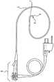
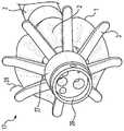
[图1]是示出根据本公开的一实施方式的具有带褶皱织带的内窥镜前端组件的示例图。[ Fig. 1 ] is an exemplary view showing an endoscope tip assembly having a pleated webbing according to an embodiment of the present disclosure.
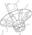
[图2]是示出根据本公开的一实施方式的示例性内窥镜前端组件的图。[ Fig. 2 ] is a diagram illustrating an exemplary endoscope tip assembly according to an embodiment of the present disclosure.
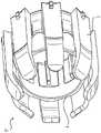
[图3]是示出根据本公开的一实施方式的示例性内窥镜前端组件的图,其中为了清楚起见省略了织带。[ Fig. 3 ] is a diagram illustrating an exemplary endoscope tip assembly according to an embodiment of the present disclosure, in which a webbing is omitted for clarity.
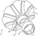
[图4]是示出根据本公开的一实施方式的示例性内窥镜前端组件的图,其中为了清楚起见省略了织带。[ Fig. 4 ] is a diagram illustrating an exemplary endoscope tip assembly according to an embodiment of the present disclosure, in which a webbing is omitted for clarity.
[图5]是示出用于收容内窥镜前端组件的示例性内窥镜的图。[ Fig. 5 ] is a diagram showing an exemplary endoscope for accommodating an endoscope tip assembly.
[图6]是示出根据本公开的一实施方式的安装于内窥镜上且处于静止位置的示例性内窥镜前端组件的图。[ Fig. 6 ] is a diagram illustrating an exemplary endoscope tip assembly mounted on an endoscope and in a rest position according to an embodiment of the present disclosure.
[图7A]是示出根据本公开的一实施方式的安装于内窥镜上且处于插入位置的示例性内窥镜前端组件的图。[ Fig. 7A ] is a diagram illustrating an exemplary endoscope tip assembly mounted on an endoscope and in an insertion position according to an embodiment of the present disclosure.
[图7B]是示出根据本公开的一实施方式的安装于内窥镜上且处于取出状态的示例性内窥镜前端组件的图。[ Fig. 7B ] is a diagram illustrating an exemplary endoscope tip assembly mounted on an endoscope and in a withdrawn state according to an embodiment of the present disclosure.
[图8]是示出根据本公开的一实施方式的安装于内窥镜上且处于取出位置的示例性内窥镜前端组件的图。[ Fig. 8 ] is a diagram illustrating an exemplary endoscope tip assembly mounted on an endoscope and in a removal position according to an embodiment of the present disclosure.
[图9A]是示出根据本公开的一实施方式的安装于内窥镜上且在结肠内处于取出位置的示例性内窥镜前端组件的图。[ FIG. 9A ] is a diagram illustrating an exemplary endoscope tip assembly mounted on an endoscope and in a removal position within a colon according to an embodiment of the present disclosure.
[图9B]是示出在结肠内具有球囊的内窥镜的图。[ Fig. 9B ] is a diagram showing an endoscope having a balloon in the colon.
[图10]是示出根据本公开的一实施方式的支撑杆处于插入位置的示例性内窥镜前端组件的图,其中为了清楚起见省略了织带。[ Fig. 10 ] is a diagram illustrating an exemplary endoscope front end assembly in which a support rod is in an inserted position according to an embodiment of the present disclosure, in which a webbing is omitted for clarity.
[图11]是示出根据本公开的一实施方式的支撑杆越过取出位置进行扩展的示例性内窥镜前端组件的图,其中为了清楚起见省略了织带。[ Fig. 11 ] is a diagram illustrating an exemplary endoscope tip assembly in which a support rod is expanded beyond a take-out position according to an embodiment of the present disclosure, in which a webbing is omitted for clarity.
[图12]是根据本公开的一实施方式的支撑杆处于静止位置的示例性内窥镜前端组件的局部放大图,其中为了清楚起见省略了织带。[ Fig. 12 ] is a partially enlarged view of an exemplary endoscope tip assembly with a support rod in a rest position according to an embodiment of the present disclosure, wherein the webbing is omitted for clarity.
[图13]是示出根据本公开的一实施方式的处于静止位置的示例性内窥镜前端组件的图,其中为了清楚起见省略了织带。[ Fig. 13 ] is a diagram showing an exemplary endoscope tip assembly in a rest position according to an embodiment of the present disclosure, wherein the webbing is omitted for clarity.
[图14]是示出根据本公开的一实施方式的内窥镜前端组件的示例性支撑杆的图。[ Fig. 14 ] is a diagram illustrating an exemplary support rod of the endoscope front end assembly according to an embodiment of the present disclosure.
[图15]是示出根据本公开的一实施方式的内窥镜前端组件的示例性支撑杆的图。[ Fig. 15 ] is a diagram illustrating an exemplary support rod of the endoscope front end assembly according to an embodiment of the present disclosure.
[图16]是示出根据本公开的一实施方式的内窥镜前端组件的示例图,其中为了清楚起见省略了织带。[ Fig. 16 ] is an exemplary diagram illustrating an endoscope tip assembly according to an embodiment of the present disclosure, in which a webbing is omitted for clarity.
[图17A]是示出根据本公开的一实施方式的安装于内窥镜上且处于静止位置的内窥镜前端组件的示例图。[ Fig. 17A ] is an exemplary diagram showing an endoscope tip assembly mounted on an endoscope and in a rest position according to an embodiment of the present disclosure.
[图17B]是根据本公开的一实施方式的安装于内窥镜上且处于静止位置的示例性内窥镜前端组件的局部立体图。[ FIG. 17B ] Is a partial perspective view of an exemplary endoscope tip assembly mounted on an endoscope and in a rest position according to an embodiment of the present disclosure.
[图18A]是示出根据本公开的一实施方式的安装于内窥镜上且处于静止位置的内窥镜前端组件的示例图。[ Fig. 18A ] is an exemplary diagram showing an endoscope tip assembly mounted on an endoscope and in a rest position according to an embodiment of the present disclosure.
[图18B]是根据本公开的一实施方式的安装于内窥镜上且处于静止位置的示例性内窥镜前端组件的局部立体图。[ FIG. 18B ] Is a partial perspective view of an exemplary endoscope tip assembly mounted on an endoscope and in a rest position according to an embodiment of the present disclosure.
[图19A]是示出根据本公开的一实施方式的处于静止位置的示例性内窥镜前端组件的图。[ Fig. 19A ] is a diagram showing an exemplary endoscope tip assembly in a rest position according to an embodiment of the present disclosure.
[图19B]是示出根据本公开的一实施方式的安装于内窥镜上且处于静止位置的内窥镜前端组件的示例图。[ Fig. 19B ] is an exemplary view showing an endoscope tip assembly mounted on an endoscope and in a rest position according to an embodiment of the present disclosure.
[图20A]是示出根据本公开的一实施方式的处于静止位置的示例性内窥镜前端组件的图。[ Fig. 20A ] is a diagram illustrating an exemplary endoscope tip assembly in a rest position according to an embodiment of the present disclosure.
[图20B]是示出根据本公开的一实施方式的处于静止位置的示例性内窥镜前端组件的图。[ Fig. 20B ] is a diagram illustrating an exemplary endoscope tip assembly in a rest position according to an embodiment of the present disclosure.
[图21A]是根据本公开的一实施方式的处于插入位置的支撑杆的剖视图。[ Fig. 21A ] is a cross-sectional view of a support rod in an inserted position according to an embodiment of the present disclosure.
[图21B]是根据本公开的一实施方式的处于静止位置的支撑杆的剖视图。[ Fig. 21B ] is a cross-sectional view of a support rod in a rest position according to an embodiment of the present disclosure.
[图21C]是根据本公开的一实施方式的处于取出位置的支撑杆的剖视图。[ Fig. 21C ] is a cross-sectional view of a support rod in a take-out position according to an embodiment of the present disclosure.
[图22]是示出根据本公开的一实施方式的带褶皱织带没有延伸到支撑杆端部的示例性内窥镜前端组件的图。[ Fig. 22 ] is a diagram illustrating an exemplary endoscope front end assembly in which the pleated webbing does not extend to the end of the support rod according to an embodiment of the present disclosure.
[图23]是示出根据本公开的一实施方式的带褶皱织带没有延伸到支撑杆端部的示例性内窥镜前端组件的图。[ Fig. 23 ] is a diagram showing an exemplary endoscope front end assembly in which the webbing with pleats does not extend to the end of the support rod according to an embodiment of the present disclosure.
[图24]是示出根据本公开的一实施方式的安装于内窥镜上且处于静止位置的内窥镜前端组件的示例图。[ Fig. 24 ] is an exemplary view showing an endoscope tip assembly mounted on an endoscope and in a rest position according to an embodiment of the present disclosure.
[图25A]是示出根据本公开的一实施方式的安装于内窥镜上且处于静止位置的内窥镜前端组件的示例图。[ Fig. 25A ] is an exemplary view showing an endoscope tip assembly mounted on an endoscope and in a rest position according to an embodiment of the present disclosure.
[图25B]是示出根据本公开的一实施方式的安装于内窥镜上且处于静止位置的内窥镜前端组件的示例图。[ Fig. 25B ] is an exemplary view showing an endoscope tip assembly mounted on an endoscope and in a rest position according to an embodiment of the present disclosure.
[图26A]是示出内窥镜前端组件的内表面的局部放大图。[ Fig. 26A ] is a partially enlarged view showing the inner surface of the endoscope tip assembly.
[图26B]是示出内窥镜前端组件的内表面的局部放大图。[ Fig. 26B ] is a partially enlarged view showing the inner surface of the endoscope tip assembly.
[图26C]是示出内窥镜前端组件的内表面的局部放大图。[ Fig. 26C ] is a partially enlarged view showing the inner surface of the endoscope tip assembly.
[图27]是示出支撑杆角度与阻力之间变化关系的图。[ Fig. 27 ] is a graph showing the relationship between the change of the support rod angle and the resistance.
[图28A]是用于说明织带不松弛条件的图。[ Fig. 28A ] is a diagram for explaining the condition that the webbing does not slack.
[图28B]是用于说明织带不松弛条件的图。[ Fig. 28B ] is a diagram for explaining the condition that the webbing does not slack.
[具体实施方式][Detailed ways]
现在将详细参考如下所述的并在附图中示出的本公开的示例性实施方式。在所有附图中,相同的参考编号尽可能地用于表示相同或相似的部件。Reference will now be made in detail to the exemplary embodiments of the present disclosure described below and illustrated in the accompanying drawings. Wherever possible, the same reference numbers will be used throughout the drawings to refer to the same or like parts.
出于本公开的目的,“内窥镜”可以表示在医疗治疗过程中插入患者体内的任何合适类型的镜头。例如,作为内窥镜列举有结肠镜、十二指肠内窥镜、胃镜、乙状结肠镜、小肠镜、尿管镜和气管支镜。术语“治疗”通常是示出为了任何目的将内窥镜插入患者体内,包括但不限于手术、活组织检查、诊断、治疗、可视化、装置的嵌入或移除以及抽吸或吸入。For the purposes of this disclosure, "endoscope" may mean any suitable type of lens that is inserted into a patient's body during medical treatment. For example, colonoscopes, duodenoscopes, gastroscopes, sigmoidoscopes, enteroscopes, ureteroscopes, and bronchoscopes are exemplified as endoscopes. The term "treatment" generally refers to the insertion of an endoscope into a patient for any purpose, including but not limited to surgery, biopsy, diagnosis, therapy, visualization, insertion or removal of devices, and aspiration or aspiration.
在提供详细描述之前,对通过以下概述构想的整个实施方式进行描述。本公开的内窥镜前端组件17被构成为扩张体内管腔使之扩展的结构,以使其附着到内窥镜的远端部分,以及在将内窥镜插入到体内管腔时变得流线型化,并且在取出内窥镜时方便对目标区域的检查。Before providing a detailed description, an overall embodiment conceived through the following overview is described. The endoscope
内窥镜前端组件17包括安装基部4。基部4被构成为:收容内窥镜的远端部分,使得基部4的内表面附着到内窥镜的外侧顶部。因此,基部4的尺寸可以设定成使得其内径略大于内窥镜顶部的直径且具有互补的形状。具体来说,如下面进一步所描述的,基部4被构成为可以收容在内窥镜的硬质顶部且可以滑动、旋转或摩擦嵌合到预定位置。如下面进一步所描述的,基部外表面可以用于在取出时支撑支撑杆的底面。
如下所述,基部4可以作为安装到支撑杆3和织带2的单个结构单元存在。如下所述,基部4可以包括单独的部件,例如轴套筒22和套筒锁23等。或者,基部4可以包括轴套筒30和套筒锁25。在另一实施方式中,基部4可以包括轴套筒27、套筒锁26和支撑杆支撑环28。在另外一种实施方式中,基部4可以包括轴套筒27和远端盖29。在上述实施方式中,构件互相配合以支撑支撑杆3和织带2且牢固地夹持内窥镜的顶部,从而防止内窥镜前端组件在治疗过程中脱落。The
基部4可以包括多个夹持窗口(gripping window)19或多个压力垫24。在取出时,支撑杆3可以戳动夹持窗口19或者按压压力垫24。当支撑杆3向夹持窗口19或压力垫24施加压力时,该力可以增加夹持窗口19或压力垫24的其中之一与内窥镜的硬质顶部的外表面之间的滑动摩擦。这种增加摩擦的自锁功能可有助于防止内窥镜前端组件17在治疗过程中从内窥镜脱落从内窥镜脱落。The
织带2与具有厚度的支撑杆3互相配合以划定从基部4扩展的折叠伞部。The
支撑杆3的横截面形状可以是具有长轴和短轴的扁平形状。换句话说,支撑杆3可以是细长形状,其中基部4的表面的法线方向上的厚度小于基部4的周向宽度。此外,支撑杆3的前端可以是弯曲形状。支撑杆3可以从基部4扩展,并且可以被构成为:在插入体内管腔时变成更加流线型化的可折叠外形,在取出时变成较大扩展的外形且相对于基部4弯曲。在可折叠结构中,支撑杆3可以被构成为:内窥镜前端组件17基本平行于安装其的内窥镜的轴线且可以折叠。在扩展后的结构中,支撑杆3可以被构成为:远离内窥镜的轴线且朝着体内管腔的周边扩展,以便缓缓按压插入有内窥镜的体内管腔。因此,在扩展时,支撑杆3可以在体内管腔的周围施加压力以便扩展围绕内窥镜前端组件17的体内管腔区域。The cross-sectional shape of the
支撑杆3沿着织带2延伸,形成互相连接于支撑杆3的表面,其方法与伞的材料在伞骨之间扩展的方法相同。织带2可以沿着支撑杆3的整个长度或沿着其部分长度延伸。织带2可以在支撑杆3的整个下方长度上延伸以接触基部4。织带2可以设置成与支撑杆3的顶部齐平。织带2可以仅覆盖支撑杆的一部分,在支撑杆3的顶部与织带2的远端边缘之间留下长度31。或者,织带2可以越过支撑杆3的顶部进行延伸。The
在扩展后的结构中,通过在支撑杆3的顶部之间扩展,并通过将支撑杆3互相连接,织带2将支撑杆3施加给体内管腔的力更均匀地分布在较大的表面区域上。In the expanded configuration, by spreading between the tops of the
代替支撑杆3把可能对体内管腔造成外伤的高压施加给管腔的这一操作,织带2和支撑杆3互相配合以形成连续的接触面。在该接触面上,扩展后的支撑杆3的力沿着体内管腔的周边分布。Instead of the operation of the
因此,代替形成以支撑杆3的接触区域的周边为中心且伴随有一些高压的接触区域,本公开的装置形成一接触区域,其中该接触区域和一些球囊装置相同,扩散更宽,压力更低。Thus, instead of forming a contact area centered around the perimeter of the contact area of the
例如,在所示实施方式中对八根支撑杆3求和计算出来的面积大致可以是480mm2,对织带2计算出来的总面积大致可以是1,670mm2。但是,被动型内窥镜前端组件17不存在像这种主动型球囊装置那样的技术限制和困难。下面进一步描述内窥镜前端组件17的示例性实施方式和细节。For example, in the illustrated embodiment, the calculated area of the eight
接下来,参考图1,图1是示出根据本公开的一实施方式的处于静止状态的示例性内窥镜前端组件17的图。内窥镜前端组件17包括基部4。如上所述,基部4可以被构成为与内窥镜的远端部分嵌合并附着于此。基部4设计成在体内管腔内操作时防止使用中的内窥镜前端组件17从内窥镜脱落。为了这个目的,例如,为了增加基部4的内表面与内窥镜顶部的外表面之间的摩擦,基部4可以包括表面加工、突起部和/或压力点。Next, reference is made to FIG. 1 , which is a diagram illustrating an exemplary
如图1所示,示例性内窥镜前端组件17可以包括一根或多根挤压肋条11。挤压肋条11可以从基部4的内表面突出以与内窥镜接触,从而增加基部4与内窥镜顶部之间的接触压力。由此,增加了滑动摩擦,并且防止了内窥镜前端组件17在治疗过程中从内窥镜脱落。挤压肋条11可以沿着基部4的轴线延伸,或者可以与轴线成一角度或垂直于轴线延伸。挤压肋条11可以包括多个单独的肋条,或者可以从基部4的一端向另一端或围绕基部4的整个周边进行延伸。As shown in FIG. 1 , an exemplary
在一些实施方式中,挤压肋条11可以形成围绕基部4周边的圆形或螺旋形设计。在一些实施方式中,挤压肋条11可以互相平行,互相成角度或者可以合适的任何配置以增加摩擦。挤压肋条11的一端可以是例如在近端部分逐渐变细的漏斗形或圆锥形。由此,可以使与所安装的内窥镜的硬质远端部分进行接合变得容易。此外,挤压肋条11可以是均质的或中空的,或者可以具有均质区域和中空区域。In some embodiments, the extruded
在与内窥镜接合时,或者在从内窥镜中取出装置期间或取出体内的内窥镜期间对内窥镜前端组件17施加压力时,挤压肋条11可构成为略微变形。如下所述,挤压肋条11可以由任何合适的材料形成。挤压肋条11可以在例如约0.2mm至约0.7mm的范围内,从基部4的内表面突出适当的距离。如下所述,包括挤压肋条11的内径可以小于内窥镜的外径。因此,包括挤压肋条11的内窥镜前端组件17的内径对于成人用装置可以在约12.75mm至约15mm的范围内,对于儿童用装置可以在约8.75mm至12mm的范围内,基部4和挤压肋条11取决于所制造材料的硬度。在没有挤压肋条11的情况下,基部4的直径对于成人用装置可以在约12.25mm至约15mm的范围内,对于儿童用装置可以在约8.25mm至12mm的范围内。基部4的内径可以是相同的直径,以便与挤压肋条11所安装的表面齐平。在另一实施方式中,基部4的内径可以与挤压肋条11所安装的表面的直径不同。The
作为示例,可用于形成基部4和挤压肋条11的材料列举有热塑性弹性体(例如,聚氨酯或山都平(注册商标))、热固性树脂(例如,橡胶和硅橡胶)或其他任何合适的材料。通过硬度计测得的形成基部4和挤压肋条11的材料的硬度可以在约20A至约70A的范围内。Examples of materials that can be used to form the
或者,基部4的内表面可以是基本上光滑的,或者可以包括在基部4的内表面延伸的表面加工模式,并且可以不包括挤压肋条11。例如,内表面可以包括用于保持内窥镜前端组件17在内窥镜上位置的涂层或表面加工。在一些实施方式中,基部4和/或基部4的内表面可以由具有较大摩擦系数的材料形成。或者,在一些实施方式中,光滑的表面或表面加工后的表面还可以包括一根或多根挤压肋条11。Alternatively, the inner surface of the
基部4的外表面可以包括一个或多个隆起部、突条部、凹口和/或纹理,以便能够帮助临床医生将内窥镜前端组件17安装到内窥镜上,并能够帮助将其从内窥镜上拆卸下来。例如,如图1所示,基部4可以包括位于其外周的一个或多个凹口12。当将内窥镜前端组件17安装到内窥镜上或将其从内窥镜拆卸下来时,凹口12可以帮助临床医生夹持基部4。The outer surface of the
基部4的整体尺寸和形状可以以内窥镜的远端部分的尺寸和形状为基准,其中内窥镜前端组件17被构成为附着到所述内窥镜的远端部分。对于成人用的内窥镜,示例性内窥镜的直径可以在约13mm至约15mm之间,对于儿童用的内窥镜,其顶部直径可以在约9mm至约12mm之间。在一些实施方式中,基部4的内径可以在约10mm至约14mm之间。此外,当内窥镜前端组件17是折叠式插入结构时,为便于插入,基部4的外径可以构成为基本小于或等于内窥镜的顶部直径且使得基部4从嵌合的内窥镜的表面略微突出。例如,基部4的外径可以在约11mm至约17mm之间。在一些实施方式中,例如,内窥镜前端组件17的基部4根据与装置一起使用的内窥镜的尺寸和/或形状,可以为各种尺寸。The overall size and shape of the
基部4的尺寸可以这样设定,使得内窥镜前端组件17在安装到内窥镜时仅接合内窥镜的最远端。许多内窥镜的最远端包括可由硬塑料或金属制成的硬质的圆柱形顶部,划定内窥镜的端部、提供刚度、和/或包住或保护位于内窥镜远端表面的光学镜片和其他结构。内窥镜的弯曲部通常紧邻该远端的金属环。许多内窥镜的弯曲部是由更加柔韧,通常更加纤细的材料制成的。因此,该弯曲有可能更容易被刺破或受损的情形,从而引起泄漏或以其他方法损坏或毁坏内窥镜的完整性。不希望牺牲内窥镜,如果在使用期间损坏,则可能会中断治疗,即无法持续治疗。The
因此,无论是正常还是不定期,都不希望使内窥镜配件在弯曲部上滑动或以其他方法将装置直接安装到内窥镜的弯曲部。为了改善这个问题,内窥镜前端组件17被设计成不是与更加纤细的弯曲部而是与内窥镜的硬质顶部互相作用。因此,基部4的尺寸可以这样设定,使得其与内窥镜的硬质顶部嵌合且不与弯曲部重叠。此外,由于内窥镜前端组件17配置在内窥镜的远端顶部,所以可以提供更好的可视性。这是因为体内管腔可以在靠近光学镜片所在的内窥镜远端表面的区域中扩展。Accordingly, it is undesirable to slide an endoscope accessory over a bend or otherwise mount a device directly to the bend of an endoscope, whether on a regular or irregular basis. To ameliorate this problem, the
然而,为了防止在使用期间从内窥镜脱落,其他装置通常被设计成装到弯曲部。为了将内窥镜配件保持在预定位置,通常被认为成非常容易的方法是,内窥镜配件与内窥镜的顶部互相作用并装到内窥镜的顶部。虽然其他装置可以被构成为位于内窥镜的较后面的位置,或者可以获得更宽的尺寸以抵抗使用期间的分离并增加与内窥镜的接触面积,但是在所公开的装置的实施方式中,它可以被构成为保持在内窥镜上的预定位置,同时可以更狭窄,且优先或排他性地接触远端的硬质隆起部。如下面进一步所描述的,例如,它可以通过使用挤压肋条11和/或其他设计来实现。在一些实施方式中,通过将内窥镜前端组件17只定位在内窥镜的硬质部分上,就可以提供更加稳固的摩擦嵌合。这是因为在设计方面无需考虑弯曲部的纤细程度。由此,基部4也可以变得更加坚硬。基部4的刚度也可助于拆卸,使临床医生在既不对组件下方的内窥镜施加压力,也不增加内窥镜前端组件17与内窥镜之间的摩擦的情况下,就可以夹持组件并施加压力。However, to prevent dislodging from the endoscope during use, other devices are often designed to fit into the bend. In order to hold the endoscope accessory in a predetermined position, it is generally considered to be very easy that the endoscope accessory interacts with and fits to the top of the endoscope. While other devices may be configured to be located at a more posterior location on the endoscope, or may be obtained in wider dimensions to resist separation during use and increase the contact area with the endoscope, in embodiments of the disclosed device , which can be configured to remain in a predetermined position on the endoscope while being narrower and preferentially or exclusively contacting the distal hard bulge. As described further below, this can be achieved, for example, through the use of extruded
内窥镜前端组件17包括从基部4向外径向扩展的折叠伞。伞由织带2和多个柔性支撑杆3形成,其中该多个柔性支撑杆被构成为弯曲状,使得折叠伞在插入状态、静止状态和取出状态之间进行转换。
内窥镜前端组件17可以包括安装在基部4上任何点的约一根至约二十根支撑杆3。例如,三根、四根、五根、六根、八根或十二根支撑杆3可以安装到基部4。支撑杆3是柔性的,并被构成为在静止位置、插入位置和取出位置之间是弯曲状。如图7A所示,在插入位置,支撑杆3被构成为沿着内窥镜的轴线向近端方向弯曲。由此,它变得流线型化,从而内窥镜可以容易地插入体内。
一旦插入体内管腔并引导至目标区域,就可以缓缓地取出内窥镜,以使目标区域可视化。当取出内窥镜时,支撑杆3可以与体内管腔接合,并可以从内窥镜的轴线向外弯曲。如图8所示,当再次取出内窥镜时,支撑杆3的顶部可以朝着远端方向弯曲。这是取出位置。如图1所示,内窥镜前端组件17在不使用时可以处于静止位置,在该位置时,支撑杆3被施力,使其从内窥镜的轴线呈喇叭状弯曲。支撑杆3在静止位置自然地向外施力,可便于在体内管腔的插入位置与取出位置之间进行转换。Once inserted into the body lumen and guided to the target area, the endoscope can be gently withdrawn to allow visualization of the target area. When the endoscope is taken out, the
在一些实施方式中,当内窥镜前端组件17处于静止位置时,支撑杆的总跨度可以在约30mm至约70mm的范围内。当内窥镜前端组件17处于插入位置时,支撑杆的总跨度可以在约12mm至约18mm的范围内。上述支撑杆的跨度可以根据治疗和患者而变化。例如,上胃肠道的管腔的平均直径有时不同于下胃肠道的平均直径或其他体内管腔的平均直径。此外,婴儿或青少年的相同体内管腔的平均直径有时不同于成人。因此,支撑杆的跨度可以反映预期的应用,或者甚至对于个别患者,在不对管腔施加不理想压力的情况下,通过确定支撑杆跨度的适当尺寸,就可以有效地促进它与管腔的接合。In some embodiments, the total span of the support rods can be in the range of about 30 mm to about 70 mm when the
支撑杆3支撑织带2,使织带2在折叠插入状态(与折叠伞相同的外形)与打开取出状态(与外翻伞相同的外形)之间进行转换。如上所述,织带2和支撑杆3在处于取出状态时互相配合,以和球囊向管腔施加压力相同的方法,通过扩散的较大表面积,形成与体内管腔的低压接触区域。例如,参考图9A。例如,内窥镜前端组件17和体内管腔接触的部分与支撑杆3的单独表面形成对比,在由织带2和支撑杆3形成的更大的表面积上扩展。由内窥镜前端组件17形成的图9A中的经扩散的接触区域与由具备球囊的内窥镜形成的扩散接触区域相同。The
在一实施方式中,如图1所示,在静止位置时,相邻的支撑杆3之间的织带2可以是松弛的。或者,如图2所示,相邻的支撑杆3之间可以基本上是不松弛的。如图1所示,织带2可以是带褶皱模式1。或者,如图2所示,它可以是无褶皱模式。不管是在带褶皱还是无褶皱的实施方式中,如图1和图2所示,织带2可以与支撑杆3的端部齐平地扩展,或者可以越过支撑杆3的端部进行扩展。在一些实施方式中,织带2可以与支撑杆3齐平地扩展以连接支撑杆3的端部,可以在支撑杆3之间的区域中越过支撑杆3的端部进行扩展,反过来也是可以的。In one embodiment, as shown in FIG. 1 , in the rest position, the
在一实施方式中,折叠伞的织带2和支撑杆3可以由不同的材料形成。例如,织带2和支撑杆3可以通过粘合剂进行互相连接。在一些实施方式中,粘合剂可以是RTV(室温硫化)粘合剂。在另一实施方式中,织带2和支撑杆3可以通过塑料焊接或高频焊接进行互相连接。在另一实施方式中,织带2和支撑杆3可以以同样方式成形。在一实施方式中,织带2的厚度可以在约0.05mm至约0.2mm的范围内。In one embodiment, the
在一些实施方式中,在织带2没有延伸到支撑杆3的下方且没有到达基部4的实施方式中,可能会出现间隙21。当内窥镜前端组件17处于取出位置,并且支撑杆3和织带2与管腔接合时,该间隙21可以允许流体和气体通过。在其他实施方式中,可以不存在间隙21。在一些实施方式中,基部4与织带2的远端边缘之间的距离可以在约1mm至约6mm之间。In some embodiments, a
在一些实施方式中,基部4可以包括多个凹口12。如上所述,凹口12可以便于临床医生夹持内窥镜前端组件17,从而有助于设置到内窥镜上和从内窥镜上拆卸下来。然而,图1中的凹口12仅是示例性的。本公开构想的有:例如,有助于临床医生夹持内窥镜前端组件17的基部4外表面上的隆起部、凹槽或表面精加工或表面加工材料等任何合适的设计或模式。In some embodiments,
织带2、支撑杆3、基部4或挤压肋条11可以由相同的材料制成,也可以由不同的材料制成。作为合适的材料,列举有热固性树脂(例如,橡胶或硅橡胶)、热塑性弹性体(例如,热塑性聚氨酯或山都平(注册商标)或其他合适的生物相容性材料)。织带2还可以由热塑性聚氨酯薄膜、任何合适的聚合物或任何合适的生物相容性材料制成。织带2、支撑杆3、基部4或挤压肋条11中的一个或多个还可以包括,例如光滑的涂层或抗菌性涂层等合适的涂层。The
接下来,参考图3和图4,图3和图4分别是示出根据本公开的其他实施方式的内窥镜前端组件17的远视图和近视图,其中为了清楚起见省略了织带2。在这些图中,可以更清楚地看到示例性基部4的内表面。如图所示,支撑杆3安装在基部4的内表面,从基部4的内表面且围绕基部4的边缘进行扩展,并且从基部4朝着支撑杆3的前端沿外径方向进行扩展。支撑杆3从基部4的内表面进行扩展,并越过基部4的边缘,从基部4呈喇叭状地扩展到支撑杆3的前端。Next, refer to FIG. 3 and FIG. 4 , which are respectively a far view and a close view showing an endoscope
在一些实施方式中,与可以是硬质的基部4相比,支撑杆3的柔性更大。下面,关于支撑杆3安装到基部4进行更详细地描述。如上所述和如这里更详细地所示,通过挤压肋条11,可以增加硬质内窥镜顶部与内窥镜前端组件17之间的滑动摩擦。挤压肋条11是一个示例,并且如上所述构想了用于增加滑动摩擦的其他方法,例如包括隆起部或表面加工。In some embodiments, the
在一些实施方式中,与可为硬质的基部4相比,支撑杆3的柔性可以更大。在一些实施方式中,支撑杆可以由硅树脂制成,基部4可以由聚碳酸酯或聚砜制成。这些材料具有相当的刚度,是医用级的,可以注塑成型,并且具有较高的玻璃化转变温度,其中该玻璃化转变温度能够在硅树脂包覆成型过程中快速固化硅树脂的支撑杆。In some embodiments, the
如果包括挤压肋条11,那么可以沿着支撑杆3,在支撑杆3之间或在两者之间进行延伸。挤压肋条11可以与支撑杆3和/或基部4分离,或者例如,如果三个全部由1种类型的材料形成,那么其可以形成为支撑杆3或基部4中其中一个的一部分,或可形成为两者的一部分。If extruded
此外,如图4所示,挤压肋条11可以沿着支撑杆3的表面延伸,支撑杆3的基部附着到基部4的内表面,并且从基部4的内表面突出。在这种实施方式中,挤压肋条11可以形成漏斗,以便更容易地接合镜头的顶部。在一些实施方式中,挤压肋条11可以由与基部4和/或支撑杆3相同的材料制成。在其他实施方式中,挤压肋条11由与基部4和/或支撑杆3不同的材料制成。In addition, as shown in FIG. 4 , the extruded
接下来,参考图5,图5是示出普通的内窥镜装置10的图。内窥镜控制部6可以包括旋钮和刻度盘,其中该旋钮和刻度盘用于临床医生通过弯曲部7在插入管5远端区域中的受控弯曲,将顶部9引导至患者。插入管5是较长的柔性管,在内窥镜10插入患者体时弯曲。弯曲部7由临床医生远程控制并边弯曲边推进管腔的拐点。例如,作为内窥镜10最远端部分的硬质顶部9收纳相机表面8。硬质顶部9是可以安装本公开的内窥镜前端组件17的位置。本公开的内窥镜前端组件17也可以不延伸到弯曲部7。这是因为,如果延伸到所述弯曲部7,那么可能会干扰临床医生控制弯曲部7弯曲的能力,或者像如上所述的那样,可能会损坏弯曲部7。Next, refer to FIG. 5 , which is a diagram showing a general endoscope device 10 . The endoscope control 6 may comprise a knob and a dial for the clinician to guide the tip 9 to the patient by controlled bending of the
接下来,参考图6,图6是示出根据本公开的一实施方式的安装在内窥镜10上且处于静止状态的内窥镜前端组件17的图。在本实施方式中,基部4的远端边缘与内窥镜7的相机表面8齐平。该位置可有助于确保内窥镜前端组件17只载置在环9上且不会干扰内窥镜10的弯曲部7的动作。然而,在一些实施方式中,基部4可以从内窥镜表面稍微缩回。在一些实施方式中,在静止状态下,支撑杆3与基部4的长边方向轴之间的角度可以在约45°至约90°之间。Next, refer to FIG. 6 , which is a diagram showing the endoscope
接下来,参考图7A,图7A是示出安装在内窥镜10上且处于插入状态的内窥镜前端组件的图。在一些实施方式中,支撑杆3与内窥镜10的长边方向轴之间的角度可以在约0°至约45°之间。在插入过程中,将支撑杆3和织带2折叠到该位置是有利的,因为这样一来实现了更小的总直径并且便于插入。如下所述,将支撑杆3和织带2弯曲到插入位置所需的力可以小于将支撑杆3和织带2弯曲到取出位置所需的力。为了将支撑杆从静止位置转换到插入位置,可能仅需要弯曲各支撑杆3的厚度的一部分。该厚度可以在约0.5mm至约1mm的范围内。另一方面,为了将支撑杆3折叠到取出位置,可能需要弯曲各支撑杆3的附加厚度或各支撑杆3的总厚度。该厚度可以在约1mm至约3mm的范围内。Next, refer to FIG. 7A , which is a diagram showing the endoscope front end assembly mounted on the endoscope 10 in an inserted state. In some embodiments, the angle between the
接下来,参考图7B,图7B是示出安装在内窥镜10上且处于取出位置的内窥镜前端组件的图。当内窥镜前端组件17处于这种位置时,支撑杆3之间的织带2可以松弛,这和处于闭合状态的伞的打褶和收束相同,如图7B所示,导致织带2的打褶或收束。在另一实施方式中,可以预先形成褶皱,使得当织带没有松弛时存在褶皱。Next, reference is made to FIG. 7B , which is a diagram showing the endoscope tip assembly mounted on the endoscope 10 and in the removal position. When the endoscope
接下来,参考图8,图8是示出安装在内窥镜10上且处于取出状态的内窥镜前端组件17的图。在一些实施方式中,在取出状态下,如果沿着从支撑杆3的顶部到与基部4接触的位置的延伸直线进行测量,那么支撑杆3与基部4的长边方向轴之间的角度可以在约50°至约180°之间。在该位置时,由支撑杆3和织带2形成且外翻伞形状的直径可以在约20mm至约30mm的范围内。Next, refer to FIG. 8 , which is a diagram showing the endoscope
当从图7A所示的插入位置(类似于闭合伞形),像伞那样外翻并取出内窥镜时,内窥镜前端组件17处于该位置。开始取出内窥镜10时,支撑杆3可以与体内管腔接合,并且该接合与取出相结合,使支撑杆3向外弯曲以远离内窥镜,从而进入取出状态。内窥镜前端组件17中的外翻伞的形状可以与管腔接触并对管腔缓缓施加向外的压力,从而与支撑杆3顶部的个别接触位置形成对比,通过在更加扩散的区域内接触更大的表面积,更加减小与引起外伤之类的与管腔的接触。使用内窥镜前端组件17实现的接触可以是,与由具备球囊的内窥镜的球囊实现的接触类型相同的方法。
接下来,参考图9A,图9A是示出结肠16内部的安装在内窥镜顶部9(隐藏在图中)上且处于取出状态的内窥镜前端组件17的图。和具备球囊的内窥镜相同,外翻伞的形状能够将向外的力均匀地分布在织带2的外周,从而更加减少引起外伤之类的与结肠壁的接触。如图9A所示,处于取出位置的内窥镜前端组件17可以对结肠施加轻微的压力,以将结肠的皱襞保持为更加扩展的结构,并提高可视性。在该方法中,可以通过外翻伞的形状拉伸结肠的皱襞,否则可以通过暴露可被这些皱襞遮挡的表面来最大限度地帮助临床医生的可视化。Next, refer to FIG. 9A , which is a diagram showing the endoscope
该形状还可以帮助稳定内窥镜顶部8,从而临床医生可以从视觉上检查结肠内部或可以更容易地进行治疗。此外,为了在内窥镜的所有侧面上向外均匀地扩展,在取出期间,支撑杆3和织带2可以在管腔的中心区域使内窥镜定位于中心,从而至少部分地抵抗重力,并且有助于对抗内窥镜顶部沿结肠壁下落的趋势或沿结肠壁拖动的趋势。The shape can also help stabilize the endoscope tip 8 so that the clinician can visually inspect the interior of the colon or treat it more easily. Furthermore, in order to spread out evenly on all sides of the endoscope, during extraction, the
接下来,参考图9B,图9B是示出结肠16内部的安装在内窥镜上的内窥镜顶部的球囊的图。与由图9A中的内窥镜前端组件17实现的接触区域相比,参考图9B中的球囊与结肠壁之间扩散的接触区域的相似性。然而,图9B中的主动球囊需要额外的设备来使球囊膨胀并对其进行控制,另一方面,图9A中的被动型内窥镜前端组件17不需要这种额外的设备或控制。此外,被动型内窥镜前端组件17直接位于内窥镜的远端顶部,另一方面,由于从内窥镜顶部到主动球囊的轴向距离更长,所以有可能降低通过扩展皱襞来改善的皱襞背面可视化的效果。Next, reference is made to FIG. 9B , which is a diagram showing the endoscope tip balloon mounted on the endoscope inside the
接下来,参考图10,图10是示出根据本公开的一实施方式的处于插入状态的内窥镜前端组件17的图,其中为了清楚起见省略了织带2。在图10的实施方式中,示出了多个夹持窗口19。基部4可以包括任何合适数量的夹持窗口19。例如,基部4可以包括零个、二个、四个、六个、八个、十个、十二个或更多个夹持窗口19。在一些实施方式中,当临床医生安装和拆卸内窥镜前端组件17时,夹持窗口19能够提供夹持辅助作用。夹持窗口19可以位于基部4的任何位置,并且可以由与基部4相同的材料或不同的材料制成。Next, refer to FIG. 10 , which is a diagram showing the endoscope
接下来,参考图11,图11是示出根据本公开的一实施方式的支撑杆3在取出状态下处于完全折叠位置的内窥镜前端组件17的图,其中为了清楚起见省略了织带2。在一些实施方式中,如果沿着内窥镜的长边方向轴进行观察,那么当内窥镜前端组件17安装在内窥镜上时,具有尽可能小的外径在取出时可能是有利的。最小外径可以通过将支撑杆3朝着内窥镜的远端部分进行折叠并潜在地越过该远端部分来达成。例如在最终将内窥镜顶部从肛门移除时等,该结构可以有助于防止体内管腔的更狭窄区域中的创伤性接触。因此,在一些实施方式中,支撑杆能够在远端方向上弯曲,并且能够定位成基本上平行于内窥镜的轴线。Next, refer to FIG. 11 , which is a diagram showing the endoscope
图10所示的支撑杆3处于插入位置所需的力小于图8和图11所示的支撑杆3处于取出位置所需的力。在一实施方式中,图10所示的支撑杆3弯曲到插入位置所需的力可以在约0.3磅至约0.4磅的范围内。在另一实施方式中,图11所示的支撑杆3处于取出位置所需的力可以在约2.6磅至约3.0磅的范围内。支撑杆3在取出时的刚度相对于在插入时的刚度的比值可以在约5至约8的范围内。The force required for the
需要较小的插入力以将支撑杆3弯曲到插入位置,这可以有助于防止治疗过程中的粘膜外伤。在插入期间,内窥镜的顶部被引导至目标区域,因此,目标是实现更小直径的流线型化以便于推进内窥镜。因此,在插入位置时,内窥镜前端组件17被构成为与内窥镜的轴线基本平行,并不旨在向结肠施加用于扩展结肠的向外的压力。Less insertion force is required to bend the
与之相反,在取出期间,内窥镜前端组件17远离内窥镜的轴线扩展,并对结肠施加用于扩张结肠且有助于可视化的力。因此,在取出位置时,支撑杆3必须能够抵抗内窥镜被取出的力,以及内窥镜被取出时由体内管腔施加的摩擦。希望能够防止取出位置的一些柔性在治疗过程中引起粘膜外伤,另一方面,如果在取出位置时柔性过大,那么如图11所示,支撑杆3可能完全弯曲到远端,从而可能无法扩展结肠并遮挡临床医生的视野,和/或可能无法将内窥镜顶部定位到结肠的中心。由于需要更大的力,以将内窥镜前端组件17像外翻的伞那样从插入位置翻转到取出位置,所以在取出时支撑杆3和织带2可以保持伞状,从而能够有助于提高可视性和顶部的稳定性。在一些实施方式中,可能会期望插入力相对于取出力的比值较小。In contrast, during extraction,
接下来,参考图12,图12是示出根据本公开的一实施方式的处于静止状态的内窥镜前端组件17的放大侧视图,其中为了清楚起见省略了织带2。确实止动件(positivestop)13能够帮助支撑杆3在取出期间保持位置和形状。如上所述,确实止动件13能够帮助支撑杆3和织带2在取出期间保持外翻伞的形状。Next, refer to FIG. 12 , which is an enlarged side view showing the
接下来,参考图13,图13是示出根据本公开的一实施方式的处于静止状态的内窥镜前端组件17的远端方向的特写图,其中为了清楚起见省略了织带2。如上所述,挤压肋条11可以包括在基部4的内表面中。挤压肋条11能够帮助增加基部4与内窥镜之间的滑动摩擦量,并且能够防止内窥镜前端组件17在治疗过程中从内窥镜脱落。Next, refer to FIG. 13 , which is a close-up view showing the distal direction of the
接下来,参考图14,图14是示出根据本公开的一实施方式的示例性支撑杆3的侧视图。支撑杆3可以以各种形状和厚度存在。在一些实施方式中,如图14的顶部20所示,支撑杆3在长度上的厚度是可以改变的,例如,支撑杆3的顶部20比中间部2薄。此外,例如,支撑杆3的基端部的横截面积比前端部大。在一些实施方式中,例如图14如所示,支撑杆3的宽度是可以改变的,顶部20可以比基部安装件14窄。例如,顶部20的宽度比中间部21窄。厚度和/或宽度上的这种差异能够导致柔性的差异,从而导致弯曲支撑杆3的不同区域所需的力的差异。或者,厚度和/或宽度沿支撑杆3可以是恒定的。Next, refer to FIG. 14 , which is a side view illustrating an
在一些实施方式中,支撑杆3的直线部分的厚度可以在约0.5mm至约3.0mm的范围内。在一些实施方式中,支撑杆3的顶部20的厚度可以在约0.5mm至约1.0mm的范围内。在一些实施方式中,支撑杆3的宽度可以在约2mm至约5mm的范围内,支撑杆3的宽度沿其长度可以是恒定的,也可以是变化的。In some embodiments, the thickness of the straight portion of the
在一些实施方式中,支撑杆3的顶部20可以在未被施力状态下,相对于中间部21向外倾斜。在一实施方式中,支撑杆3的顶部20的角度可以在约110°至约160°的范围内。当向顶部20倾斜时,在取出期间可以通过获取管腔的表面来帮助支撑杆3与管腔接合。这种增强的接合可以帮助支撑杆3和织带2像伞那样外翻,从而实现取出状态。各支撑杆的至少一部分的顶部的厚度相对较薄,刚度相对较低,并且由于前端是弯曲形状,所以在与管腔接合时和在取出状态时,内窥镜组件17是柔性的且将损伤降到了最低。如果支撑杆3是扁平板状,那么其在厚度方向上易于弯曲,但是在宽度方向上难以变形。因此,在将内窥镜的插入部从体内拔出时,支撑杆3在圆周方向上难以扭曲和弯曲,但是可以在拔出方向上适当地变形。In some embodiments, the top 20 of the
支撑杆3和织带2被构成为在取出过程中接触周围的体内管腔以稳定内窥镜的顶部并提高可视性。此外,支撑杆3需要与体内管腔互相作用,以便从插入位置转换到取出位置。因此,支撑杆3的至少一部分的长度由插入其中的体内管腔的直径限定。在一些实施方式中,从支撑杆3的确实止动件13到最远顶部的长度可以在约10mm至约25mm的范围内。The
接下来,参考图15,图15是示出根据本公开的一实施方式的支撑杆3的侧视图。在本实施方式中,支撑杆3包括一个或多个槽口15。槽口15可能会在支撑杆3的近侧对向面与远端对向面之间产生刚度差异。例如,与没有槽口15的支撑杆3的表面相比,具有槽口15的支撑杆3的表面仅需要更小的力就可以向自身内侧弯曲。在一些实施方式中,支撑杆3的一个表面与另一个表面之间的这种差异可以允许支撑杆3在一个方向上优先于另一个方向进行弯曲。Next, refer to FIG. 15 , which is a side view illustrating a
在一些实施方式中,支撑杆3可以具有一个或多个槽口15。在一些实施方式中,槽口15可以仅位于支撑杆3的直线部分。在其他实施方式中,槽口可以位于支撑杆3的直线部分和成角度部分20的两者。在其他实施方式中,如图14所示,可以不存在槽口15。槽口15可以是任何合适的形状,例如狭缝、矩形、三角形、U型或锥形横截面等。在带槽口表面上所形成的间隙本身可以收缩,因此槽口的形状可以影响支撑杆3的柔性。In some embodiments, the
接下来,参考图16,图16是示出根据本公开的一实施方式的支撑杆3上存在槽口15的内窥镜前端组件17的远端的斜视图,其中为了清楚起见省略了织带2。图16是支撑杆3处于静止位置的图,和当支撑杆3存在槽口15时如图3所示的没有槽口的支撑杆3的位置相同。Next, refer to FIG. 16 , which is an oblique view showing the distal end of the endoscope
接下来,参考图17A,图17A是示出根据本公开的示例性实施方式的安装在内窥镜10上且处于静止状态的内窥镜前端组件17的图。轴套筒22和套筒锁23可以互相配合以防止内窥镜前端组件17从内窥镜脱落,并且在取回时为支撑杆3提供支撑和刚度。套筒锁23可以是锥形的,使得远端部分的内径略大于近端部分的内径。在一实施方式中,套筒锁23的远端部分的直径可以在约13.8mm至约15.5mm范围内。在另一实施方式中,套筒锁23的近端部分的直径可以在约12.8mm至约15.0mm范围内。和套筒锁23相同,轴套筒22也可以是锥形的,使得轴套筒22的近端部分的外径略大于远端部分的外径。在一实施方式中,远端部分的外径可以在约13.3mm至约15.5mm的范围内。在另一实施方式中,近端部分的外径可以在约13.8mm至约16mm的范围内。轴套筒22和套筒锁23的锥形特征能够有助于在取出时增加轴套筒22与硬质顶部9之间的滑动摩擦,此时,支撑杆能够受到向远端方向弯曲的力并按压套筒锁23。锥形部分可以接合并增加轴套筒22与硬质顶部9之间的压力和摩擦力。由此,能够防止内窥镜前端组件17从内窥镜脱落。Next, refer to FIG. 17A , which is a diagram showing the endoscope
接下来,参考图17B,图17B是示出根据本公开的一实施方式的安装于内窥镜上且处于静止位置的示例性内窥镜前端组件的局部立体图。在立体图中,示出了套筒锁23的近端部分与远端部分之间的厚度差异以及其如何接触轴套筒22。在一实施方式中,轴套筒22和套筒锁23可以由相同的材料制成。在另一实施方式中,轴套筒22和套筒锁23可以由不同的材料制成。套筒锁23的宽度可以在约2mm至约10mm的范围内。Next, reference is made to FIG. 17B , which is a partial perspective view illustrating an exemplary endoscope tip assembly mounted on an endoscope and in a rest position in accordance with an embodiment of the present disclosure. In a perspective view, the difference in thickness between the proximal and distal portions of the
接下来,参考图18A,图18A是示出根据本公开的一实施方式的安装于内窥镜上且处于静止位置的示例性内窥镜前端组件的图。在一实施方式中,可以存在多个压力垫24。在一些实施方式中,可以存在约四个至约十二个压力垫24。在取出时,支撑杆3可以按压压力垫24以施加压力。当压力施加到压力垫24时,基部4与内窥镜10的硬质顶部9之间的滑动摩擦可能会增加,由此,能够防止内窥镜前端组件17在治疗过程中脱落。Next, reference is made to FIG. 18A , which is a diagram illustrating an exemplary endoscope tip assembly mounted on an endoscope and in a rest position, according to an embodiment of the present disclosure. In one embodiment, there may be
接下来,参考图18B,图18B是示出根据本公开的一实施方式的安装于内窥镜上且处于静止位置的示例性内窥镜前端组件的局部立体图。在该立体图中,示出了套筒锁25与压力垫24和轴套筒30之间的接触。如上所述,在取出时,支撑杆3可以按压压力垫24以施加压力,由此,可以增加轴套筒30与内窥镜10的硬质顶部9之间的压力。在一实施方式中,轴套筒30和套筒锁25可以是单独的构件。在另一实施方式中,轴套筒30和套筒锁25可以是一个构件。在一实施方式中,各压力垫24的长度可以在约2mm至约7mm的范围内。在另一实施方式中,各压力垫24的宽度可以在约2mm至约5mm的范围内。Next, reference is made to FIG. 18B , which is a partial perspective view illustrating an exemplary endoscope tip assembly mounted on an endoscope and in a rest position in accordance with an embodiment of the present disclosure. In this perspective view, the contact between the
在一实施方式中,轴套筒30和套筒锁25可以由相同的材料制成。在另一实施方式中,轴套筒30和套筒锁25可以由不同的材料制成。In one embodiment, the
接下来,参考图19A,图19A是示出根据本公开的一实施方式的处于静止位置的示例性内窥镜前端组件的局部分解图。在一实施方式中,基部4可以包括轴套筒27、套筒锁26和支撑杆支撑环28。这三个构件可以互相配合,以防止内窥镜前端组件17在治疗过程中脱落,和/或提供支撑杆3在取出时可以按压的硬质表面,并增加轴套筒27与内窥镜10的硬质顶部9之间的滑动摩擦。该配置可以提供脱离力,其中该脱离力大于内窥镜前端组件17摩擦配合到内窥镜顶部所需的力。在一实施方式中,套筒锁26与轴套筒27之间的摩擦系数可以小于轴套筒27与硬质顶部9之间的摩擦系数。套筒锁26可以包括肋条11,肋条11可用于向轴套筒27施加额外的压力,由此增加了轴套筒27与内窥镜10的硬质顶部9之间的滑动摩擦。Next, reference is made to FIG. 19A , which is a partially exploded view illustrating an exemplary endoscope tip assembly in a rest position, according to an embodiment of the present disclosure. In one embodiment, the
在一实施方式中,轴套筒27,套筒锁26和支撑杆支撑环28可以由相同的材料制成。在另一实施方式中,轴套筒27,套筒锁26和支撑杆支撑环28可以由不同的材料制成。挤压肋条11具有上述特征。In one embodiment, the
套筒锁26的内径逐渐变细,并且直径朝着近端部分增大。锥形角度可以在约0.5°至约2.5°的范围内。轴套筒27的外径也沿相同的方向逐渐变细,并且远端部分的直径小于近端部分的直径。轴套筒27的锥形角度可以在约0.5°至约2.5°之间变化。The inner diameter of the
在一实施方式中,套筒锁26的远端部分的内径可以与轴套筒27的远端部分的外径相同。在另一实施方式中,套筒锁26的远端部分的内径可以略小于轴套筒27的远端部分的外径。例如,在一实施方式中,成人用的结肠镜的套筒锁26的内径可以在约14mm至约16mm之间。在另一实施方式中,轴套筒27的外径可以在约14mm至约15.5mm之间。在一实施方式中,套筒锁26的宽度可以与轴套筒27的宽度大致相同。在另一实施方式中,套筒锁26的宽度可以不同于轴套筒27的宽度。在一实施方式中,套筒锁26的宽度可以在约5mm至约10mm之间。在另一实施方式中,套筒锁26的厚度可以在约0.4mm至约1.5mm的范围内。在另一实施方式中,轴套筒27的厚度可以在约0.3mm至约0.75mm之间。在一实施方式中,支撑杆支撑环28的厚度可以在约0.3mm至约1.0mm的范围内。In one embodiment, the inner diameter of the distal portion of the
接下来,参考图20A和图20B,图20A和图20B是示出根据本公开的一实施方式的处于静止位置的示例性内窥镜前端组件的图。在一实施方式中,基部4可以包括远端盖29和轴套筒27。这两个构件可以互相配合,以防止内窥镜前端组件17在治疗过程中脱落,和/或提供支撑杆3在取出时可以按压的硬质表面,并增加轴套筒27与内窥镜10的硬质顶部9之间的滑动摩擦。此外,当远端盖29越过内窥镜10的端部进行延伸时,能够帮助抑制管腔,使得相机8不会阻挡视野。远端盖29的内径可以与轴套筒27的外径大致相同。在另一实施方式中,远端盖29的内径可以不同于轴套筒27的外径。在一实施方式中,远端盖29的内径可以在约12mm至约17mm的范围内。在另一实施方式中,轴套筒27的外径可以在约13mm至约15mm之间。在一实施方式中,例如,如图20A所示,远端盖29的宽度沿周边可以是均匀的,并且可以在约2mm至约8mm的范围内。在另一实施方式中,例如,如图20B所示,远端盖的宽度可以是变化的。在一些实施方式中,远端盖29的宽度可以沿盖的周边变化,并且其宽度可以在约2mm至约12mm的范围内。Next, reference is made to FIGS. 20A and 20B , which are diagrams illustrating an exemplary endoscope tip assembly in a rest position, according to an embodiment of the present disclosure. In one embodiment, the
接下来,参考图21A,图21A是示出根据本公开的一实施方式的处于插入位置的支撑杆的剖视图。如A所示,基部4总是附着在支撑杆3上,但是在C中并不总是附着在支撑杆3上。在插入时将支撑杆3向近端方向弯曲所需的插入力finsertion可以小于在取出时所需的力Fwithdrawal。这是因为试图将支撑杆3保持在静止位置的阻力rinsertion是支撑杆3的厚度tinsertion的三次函数,并且该厚度可以在取出时的支撑杆3的厚度Twithdrawal的约30%至约60%的范围内。此外,当插入内窥镜前端组件17时,它们在确实止动件13与基部4之间的C处不存在接触。Next, refer to FIG. 21A , which is a cross-sectional view illustrating a support rod in an inserted position according to an embodiment of the present disclosure. As shown in A, the
接下来,参考图21B,图21B是示出根据本公开的一实施方式的处于静止位置的支撑杆的剖视图。在静止位置时,它们在基部4与支撑杆3的确实止动件13之间的C处存在接触。Next, refer to FIG. 21B , which is a cross-sectional view illustrating a support rod in a rest position according to an embodiment of the present disclosure. In the rest position, they are in contact at C between the
接下来,参考图21C,图21C是示出根据本公开的一实施方式的处于取出位置的支撑杆的剖视图。在取出时,基部4与支撑杆3的确实止动件13之间的C处存在接触。此外,取出期时的弯曲阻力Rwithdrawal是取出时的支撑杆的总厚度Twithdrawal的三次函数,其可以远大于插入期间的阻力rinsertion。该取出阻力Rwithdrawal能够帮助支撑杆3和织带2在取出时保持像外翻伞那样的形状。Next, refer to FIG. 21C , which is a cross-sectional view illustrating a support rod in a removal position according to an embodiment of the present disclosure. On extraction, there is contact at C between the
接下来,参考图22,图22是示出根据本公开的一实施方式的带褶皱织带没有延伸到支撑杆端部的示例性内窥镜前端组件的图。长度31表示支撑杆3的顶部与织带2的边缘之间的距离。在一些实施方式中,如图1所示,长度31可以是0mm。在一些实施方式中,长度31可以在约0mm至约15mm的范围内。在其他实施方式中,长度31可以在约3mm至约10mm的范围内。如果该长度31大于0mm,那么遮挡相机视野的织带2可能会变少,所以在治疗过程中能够促进结肠内部更好的可视化。Next, reference is made to FIG. 22 , which is a diagram illustrating an exemplary endoscope front end assembly in which the pleated webbing does not extend to the end of the support rod according to an embodiment of the present disclosure. The length 31 represents the distance between the top of the
接下来,参考图23,图23是示出根据本公开的一实施方式的示例性内窥镜前端组件的图。在图23所示的内窥镜前端组件中,带褶皱织带2的一端在支撑杆3弯曲的位置(中间部21与顶部20之间的角度发生变化的位置)连接,并且没有延伸到支撑杆3的顶部20。图23提供了图22所示的实施方式的替代图,其中长度31是非零距离。由于织带2没有延伸到顶部20,所以从体内拔出时的阻力不会增加太多。根据这种结构,支撑杆3直线延伸的范围是织带2的连接范围,因此无需使织带2符合支撑杆3的弯曲形状,并且易于制造。Next, refer to FIG. 23 , which is a diagram illustrating an exemplary endoscope tip assembly according to an embodiment of the present disclosure. In the endoscope front end assembly shown in FIG. 23 , one end of the
接下来,参考图24,图24是示出根据本公开的一实施方式的安装于内窥镜上且处于静止位置的示例性内窥镜前端组件的图。如图6所示,长度31可以是0mm,或者在一些实施方式中,例如,如图24所示,长度31可以在约0mm至约15mm的范围内。在一些实施方式中,织带2的径向长度可以在支撑杆长度的约25%至约100%的范围内。Next, reference is made to FIG. 24 , which is a diagram illustrating an exemplary endoscope tip assembly mounted on an endoscope and in a rest position in accordance with an embodiment of the present disclosure. As shown in FIG. 6, length 31 may be 0 mm, or in some embodiments, for example, as shown in FIG. 24, length 31 may range from about 0 mm to about 15 mm. In some embodiments, the radial length of the
接下来,参考图25A,图25A是示出根据本公开的一实施方式的安装于内窥镜上且处于静止位置的示例性内窥镜前端组件的图。例如,如图6所示,长度31可以是0mm,或者在一些实施方式中,例如,如图24所示,长度31可以在约0mm至约15mm的范围内。在一实施方式中,基部4可以包括远端盖29和轴套筒27。这两个构件可以互相配合以帮助抑制管腔,使得相机8不会阻挡视野。在一实施方式中,例如,如图25A所示,远端盖的宽度沿周边可以是均匀的,并且可以在约2mm至约8mm的范围内。在另一实施方式中,例如,如图25B所示,远端盖29的宽度可以沿盖的周边变化,并且其宽度可以在约2mm至约12mm的范围内。Next, reference is made to FIG. 25A , which is a diagram illustrating an exemplary endoscope tip assembly mounted on an endoscope and in a rest position, according to an embodiment of the present disclosure. For example, as shown in FIG. 6, length 31 may be 0 mm, or in some embodiments, for example, as shown in FIG. 24, length 31 may range from about 0 mm to about 15 mm. In one embodiment, the
在本公开的一实施方式中,内窥镜前端组件17被构成为这样,使得安装有该内窥镜前端组件17的内窥镜从体内拔出的力大于插入体内的力(即,存在插拔力差值)。这里,插拔力差值被定义为:具备内窥镜前端组件17的内窥镜从体内拔出的力减去插入体内的力而获得的差值。In one embodiment of the present disclosure, the endoscope
上述插拔力差值根据支撑杆3的厚度、形状以及材质等因素而变化。此外,插拔力差值与内窥镜被拔出时支撑杆3相对于基部4的角度相关。或者,拔出力的大小取决于内窥镜被拔出时支撑杆3相对于基部4的角度。内窥镜前端组件17具有设置在支撑杆3之间的间隙中的织带2,拔出力的大小还取决于上述织带2的结构(安装区域、硬度(差异)以及面积等)。The aforementioned insertion and withdrawal force difference varies according to factors such as the thickness, shape, and material of the
下面的表1示出了通过改变支撑杆3的厚度和形状等而制成的各内窥镜前端组件的插拔力测量结果。插拔力的测量方法如下:将内窥镜前端组件安装到推拉力计上,并将内窥镜前端组件插入内径为24mm和29mm的丙烯酸管(长度L=150mm)中,然后测量插入时和拔出时的最大力,并分别用作插入力和拔出力。将插入时和拔出时的速度设为75mm/s。此外,对于测量,考虑到肠管直径的多样性,因此使用多个内径的丙烯酸管进行测量。Table 1 below shows the results of measurement of the insertion and withdrawal force of each endoscope tip assembly manufactured by changing the thickness, shape, etc. of the
[表1][Table 1]

单位为(N)The unit is (N)
如上所述,对于表1中所描述的#1至#9的各个内窥镜前端组件,使用通过模拟大肠制成的大肠模型,对可插入性和可观察性进行了评估。这里,可观察性是示出内窥镜被拔出时能否很好地观察到大肠的指标。As described above, for each endoscope
对于#1,由于没有获得足够的插拔力差值,并且缺乏可观察性,因此导致了可插入性和可观察性无法兼得的结果。For #1, due to the lack of sufficient insertion force difference and lack of observability, it leads to the result that both pluggability and observability cannot be achieved at the same time.
对于#2至#8,可插入性和可观察性都很好。特别是,对于#3至#6,在评估可观察性时(即从大肠模型中拔出内窥镜时),总是获得良好的可观察性。For #2 to #8, both pluggability and observability are fine. In particular, for #3 to #6, good observability was always obtained when assessing observability (i.e., when the endoscope was pulled out from the large intestine model).
对于#8,在有些位置拔出时的可拔出性并不好。For #8, the extractability is not good when extracting in some positions.
对于#9,插拔力差值过大,可插入性和可观察性无法兼得。For #9, the difference in insertion and extraction force is too large, and both insertability and observability cannot be achieved at the same time.
如上所述,通过调整内窥镜前端组件17的结构,可以提高可观察性,例如提高肠管褶皱背面的病变的检测精度。如上所述,重要的是可兼得内窥镜的可插入性和可观察性。As mentioned above, by adjusting the structure of the endoscope
<挤压肋条的变形例><Modification of Extruded Rib>
近年来,由于诸如女性医师活跃等医师的多样化,需要一种能够容易地安装并且防止脱落的内窥镜前端组件。下面,列举内窥镜前端组件的另一个示例。In recent years, due to diversification of physicians such as active female physicians, an endoscope tip assembly that can be easily installed and is prevented from coming off is required. Next, another example of an endoscope front end assembly is listed.
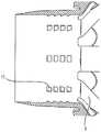
图26A、26B和26C是示出内窥镜前端组件17的内表面的局部放大图。在与内窥镜接触的内表面上,图26A、26B和26C中的内窥镜前端组件17分别具有多根挤压肋条11。上述多根挤压肋条11沿着内窥镜的插入方向倾斜,挤压肋条11的高度从内窥镜前端组件17的开口端侧向内增加。因此,随着向内窥镜前端组件17中插入,内窥镜从内窥镜前端组件17接收的抗力增大。也就是说,随着向随着内窥镜前端组件17中插入,插入方向上的摩擦力增大。26A , 26B and 26C are partial enlarged views showing the inner surface of the
另一方面,当从内窥镜取出内窥镜前端组件17时,上述挤压肋条11的最突出部分继续与内窥镜接触,因此在内窥镜从内窥镜前端组件17拔出一定长度之前,摩擦力大体是恒定的。On the other hand, when the endoscope
因此,对于具有上述形状的凸部11的内窥镜前端组件17,将内窥镜前端组件17安装到内窥镜所需的安装力小于将内窥镜前端组件17从内窥镜拆卸所需的拆卸力。Therefore, for the
在图26A所示的示例中,内窥镜前端组件17在内表面上沿着内窥镜的插入方向设置有多根挤压肋条11。这样一来,将内窥镜前端组件17安装到内窥镜所需的安装力小于将内窥镜前端组件17从内窥镜拆卸所需的拆卸力。In the example shown in FIG. 26A , a plurality of pressing
在图26B所示的示例中,对于挤压肋条11,随着从内窥镜前端组件17的开口端侧向内侧插入,内窥镜前端组件17的内表面的周向宽度增加。这样一来,将内窥镜前端组件17安装到内窥镜所需的安装力小于将内窥镜前端组件从内窥镜拆卸所需的拆卸力。In the example shown in FIG. 26B , as for the
在图26C所示的示例中,挤压肋条11是V形的,并且在从内窥镜前端组件17的开口端侧朝着内侧的方向上分叉。这样一来,将内窥镜前端组件17安装到内窥镜所需的安装力小于将内窥镜前端组件17从内窥镜拆卸所需的拆卸力。In the example shown in FIG. 26C , the
下面的表2示出了通过改变图26B的挤压肋条11的厚度、大小、数量和形状等而制成的各内窥镜前端组件的拆装力测量结果。通过以下方法进行测量。Table 2 below shows the measurement results of the detachment force of each endoscope front end assembly made by changing the thickness, size, number, shape, etc. of the
1.将各内窥镜前端组件安装到外径为13.1mm和13.2mm的针规上,并从塑料板上方使用推拉力计测量插入针规时的最大力值(安装力)。1. Install each endoscope front-end assembly on a needle gauge with an outer diameter of 13.1mm and 13.2mm, and use a push-pull force gauge from above the plastic plate to measure the maximum force value (installation force) when inserting the needle gauge.
2.将内窥镜前端组件安装到外径为13.1mm和13.2mm的针规上,并固定内窥镜前端组件的基部,然后测量使用推拉力计将针规拔出时的最大力值(拆卸力)。2. Install the endoscope front-end assembly on needle gauges with an outer diameter of 13.1mm and 13.2mm, and fix the base of the endoscope front-end assembly, and then measure the maximum force value when the needle gauge is pulled out using a push-pull force gauge ( removal force).
[表2][Table 2]

单位为(N)The unit is (N)
当安装力小于等于45N时,内窥镜前端组件17不会干扰对内窥镜的安装。When the installation force is less than or equal to 45N, the endoscope
当拆卸力大于等于20N且小于等于45N时,内窥镜前端组件17不会干扰对内窥镜的拆卸。When the detachment force is greater than or equal to 20N and less than or equal to 45N, the endoscope
当具有内窥镜前端组件17的内窥镜从体内拔出时,为了内窥镜前端组件17的脱落,具有内窥镜前端组件17的内窥镜从体内拔出的拔出力需要小于内窥镜前端组件17的拆卸力。优选的是,所述拔出力比所述拆卸力至少小1N。更优选的是,内窥镜前端组件17的拆卸力与安装力的差小于等于3N。When the endoscope with the endoscope
<支撑杆阻力的进一步说明><Further Explanation of Support Rod Resistance>
图27是示意性地表示一实施方式中的支撑杆3和基部4形成的角度(与内窥镜前端的插入方向相反的轴方向设为0°,并将逆时针设为正角度)与使支撑杆3从内窥镜基端侧向前端侧倾斜所需的力(支撑杆阻力)之间关系的曲线图。27 schematically shows the angle formed by the
表示阻力的曲线图的阶差(位移点)是由收容基部4的凹部的应用(凹部的一部分抵靠在基部4上),织带2的松弛消除和支撑杆3的切口等引起的。上述曲线图是理想化的,并且在由弹性体构成的内窥镜前端组件17中是平滑的曲线,构成上述阶差的不连续点表现为曲线的拐点。由于其阻力在多个阶段中变化,所以本实施方式中的内窥镜前端组件17的支撑杆3能够通过更佳的摩擦力来支撑肠壁的皱襞。The steps (displacement points) of the graph representing the resistance are caused by the application of the recess housing the base 4 (a part of the recess rests on the base 4), the removal of slack in the
在一些实施方式中,提供了一种改善内窥镜检查过程中的可视化的方法,本公开的内窥镜前端组件在治疗之前安装到内窥镜的远端部分。In some embodiments, providing a method of improving visualization during an endoscopy, an endoscope tip assembly of the present disclosure is mounted to the distal portion of the endoscope prior to treatment.
在一些实施方式中,提供了一种改善内窥镜检查过程中的内窥镜稳定性的方法,本公开的内窥镜前端组件在治疗之前安装到内窥镜的远端部分。In some embodiments, a method of improving endoscope stability during an endoscopy procedure is provided in which an endoscope tip assembly of the present disclosure is mounted to a distal portion of the endoscope prior to treatment.
在一些实施方式中,提供了一种外伤较少的内窥镜检查治疗方法,本公开的内窥镜前端组件在治疗之前安装到内窥镜的远端部分。In some embodiments, to provide a less traumatic endoscopic treatment method, an endoscope tip assembly of the present disclosure is mounted to the distal portion of the endoscope prior to treatment.
本公开中参考内窥镜安装支架的示例性实施方式描述了本发明,其中该内窥镜安装支架用于进行医疗治疗之类的特定应用中,然而应当理解的是,本说明书中所描述的实施方式并不限定于此。例如,镜头和相同的装置常用于工业应用中,例如机械类的检查和/或修理等。本公开的内窥镜安装支架还可以与医疗环境之外的工业镜头一起使用。本领域技术人员和本说明书所提供的指教的访问者应当理解,附加的变更、附加的应用、附加的实施方式和等同物的替代均包含在所公开的实施方式的范围内。因此,所公开的实施方式不应被视为受上述或下述描述的限制。The present invention is described in this disclosure with reference to an exemplary embodiment of an endoscope mounting bracket for use in a particular application such as performing a medical treatment, however it should be understood that what is described in this specification Embodiment is not limited to this. For example, lenses and similar devices are commonly used in industrial applications, such as inspection and/or repair of machinery, etc. The endoscope mount of the present disclosure may also be used with industrial lenses outside of medical settings. Those skilled in the art and readers of the teachings provided in this specification will appreciate that additional changes, additional applications, additional implementations and substitutions of equivalents are within the scope of the disclosed embodiments. Therefore, the disclosed embodiments should not be considered as limited by the above or below description.
根据详细的说明书,本公开的许多特征和优点将显而易见,因此,所附权利要求旨在覆盖包括在本公开的精神和范围内的本公开的所有这些特征和优点。此外,本领域技术人员可轻易想到许多修改和変化,因此不希望将本公开限制于所示出和所描述的精确配置和操作。因此,可以使用所有合适的修改和等同物,包含在本公开的范围内。The many features and advantages of the present disclosure will be apparent from the detailed description, and thus, it is intended by the appended claims to cover all such features and advantages of the present disclosure as included within the spirit and scope of the present disclosure. In addition, many modifications and changes will readily occur to those skilled in the art, and thus it is not desired to limit the disclosure to the precise configuration and operation shown and described. Accordingly, all suitable modifications and equivalents may be used and are encompassed within the scope of this disclosure.
此外,本领域技术人员应当理解的是,本公开的基本概念可以很容易地用作其他结构,方法和系统的设计基础,从而实现本公开的一些目的。因此,权利要求不应被认为受上述描述的限制。In addition, those skilled in the art should understand that the basic concept of the present disclosure can be easily used as the design basis of other structures, methods and systems, so as to achieve some of the purposes of the present disclosure. Accordingly, the claims are not to be seen as limited by the foregoing description.
下面,将描述本公开的实施方式的示例。在不产生矛盾的范围内,这些实施方式的示例可以部分地替换或互相组合。Next, examples of embodiments of the present disclosure will be described. Examples of these embodiments may be partially replaced or combined with each other within a range that does not create a contradiction.
[1][1]
一种内窥镜前端组件,其具有:环形基部,用于收容内窥镜的一端;可折叠的多个支撑杆,从所述基部呈放射状延伸,其中,具备所述内窥镜前端组件的所述内窥镜从体内拔出的力大于插入体内的力。An endoscope front-end assembly, which has: an annular base for accommodating one end of the endoscope; a plurality of foldable support rods extending radially from the base, wherein the endoscope front-end assembly is equipped with The force with which the endoscope is pulled out from the body is greater than the force with which it is inserted into the body.
[2][2]
根据[1]所述的内窥镜前端组件,其中,所述内窥镜从所述体内拔出时的所述支撑杆相对于所述基部的角度与插拔力差值相关,其中所述插拔力差值是从所述体内拔出的力减去所述插入力而获得的值。The endoscope front end assembly according to [1], wherein, when the endoscope is pulled out from the body, the angle of the support rod relative to the base is related to the difference in insertion force, wherein the The insertion-extraction force difference is a value obtained by subtracting the insertion force from the extraction force from the body.
[3][3]
根据[2]所述的内窥镜前端组件,其中,所述插拔力差值在0.5~10N的范围内。According to the endoscope front-end assembly described in [2], wherein, the difference in insertion and withdrawal force is in the range of 0.5-10N.
[4][4]
根据[2]所述的内窥镜前端组件,其中,所述插拔力差值在1.0~4.0N的范围内。According to the endoscope front-end assembly described in [2], wherein, the difference in insertion and withdrawal force is within the range of 1.0-4.0N.
[5][5]
根据[2]所述的内窥镜前端组件,其中,所述插拔力差值在2~3.0N的范围内。According to the endoscope front-end assembly described in [2], wherein, the difference in insertion and withdrawal force is in the range of 2-3.0N.
[6][6]
根据[1]所述的内窥镜前端组件,其中,所述插入力小于等于5.0N。The endoscope front end assembly according to [1], wherein the insertion force is less than or equal to 5.0N.
[7][7]
根据[1]所述的内窥镜前端组件,其中,所述插入力小于等于2.0N。The endoscope front end assembly according to [1], wherein the insertion force is less than or equal to 2.0N.
[8][8]
根据[1]所述的内窥镜前端组件,其中,所述插入力小于等于0.5N。The endoscope front end assembly according to [1], wherein the insertion force is less than or equal to 0.5N.
[9][9]
根据[1]所述的内窥镜前端组件,其中,所述拔出力在0.5~10N的范围内。The endoscope tip assembly according to [1], wherein the pull-out force is within a range of 0.5 to 10N.
[10][10]
根据[1]所述的内窥镜前端组件,其中,所述拔出力在1~4.5N的范围内。The endoscope tip assembly according to [1], wherein the pull-out force is within a range of 1 to 4.5N.
[11][11]
根据[1]所述的内窥镜前端组件,其中,所述拔出力在2~3.5N的范围内。The endoscope tip assembly according to [1], wherein the pull-out force is within a range of 2 to 3.5N.
[12][12]
根据[1]所述的内窥镜前端组件,其中,所述拔出力的大小根据所述多个支撑杆相对于所述基部的角度而变化。The endoscope front end assembly according to [1], wherein a magnitude of the pull-out force varies according to an angle of the plurality of support rods with respect to the base.
[13][13]
根据[1]所述的内窥镜前端组件,其中,在所述多个支撑杆之间分别设有织带,所述拔出力的大小根据所述织带的材质,形状,大小或配置位置而变化。According to the endoscope front-end assembly described in [1], wherein, a webbing is respectively provided between the plurality of support rods, and the pull-out force is determined according to the material, shape, size or arrangement position of the webbing Variety.
[14][14]
一种内窥镜前端组件,其具有:环形基部,用于收容内窥镜的一端;可折叠的多个支撑杆,从所述基部呈放射状延伸,其中,所述多个支撑杆分别具有用于收容所述基部的凹部。A front-end assembly of an endoscope, which has: an annular base for accommodating one end of the endoscope; a plurality of foldable support rods extending radially from the base, wherein each of the plurality of support rods has a It is accommodated in the concave portion of the base.
[15][15]
根据[14]所述的内窥镜前端组件,其中,还具备织带,所述织带将所述多个支撑杆互相约束。The endoscope tip assembly according to [14], further comprising a webbing that constrains the plurality of support rods to each other.
[16][16]
根据[14]所述的内窥镜前端组件,其中,所述凹部的一部分固定到所述基部的内表面,并且所述凹部的另一部分与所述基部可拆装地接触。The endoscope tip assembly according to [14], wherein a part of the recess is fixed to an inner surface of the base, and another part of the recess is in detachable contact with the base.
[17][17]
根据[14]所述的内窥镜前端组件,其中,对于所述多个支撑杆,在所述支撑杆没有受到外力的状态下向所述内窥镜前端组件的前方或后方倾斜所需的力与所述支撑杆厚度的立方成比例。The endoscope front end assembly according to [14], wherein, for the plurality of support rods, what is required to tilt forward or rearward of the endoscope front end assembly in a state where the support rods are not subjected to external force The force is proportional to the cube of the thickness of the strut.
[18][18]
一种内窥镜前端组件,具备:环形基部,能够可拆装地安装到内窥镜插入部的远端部分,外层由第1聚合物形成,内层由硬度小于第1聚合物的第2聚合物形成;以及可折叠的多个支撑杆,由所述第2聚合物形成,并且从所述基部呈放射状延伸。A front end assembly of an endoscope, comprising: an annular base capable of being detachably mounted to a distal portion of an insertion portion of an endoscope, an outer layer formed of a first polymer, and an inner layer formed of a first polymer having a hardness less than that of the first polymer. 2 polymers; and a collapsible plurality of struts formed from said second polymer and extending radially from said base.
[19][19]
根据[18]所述的内窥镜前端组件,其中,所述支撑杆与所述外层之间的硬度差大于等于硬度A10。The endoscope front end assembly according to [18], wherein the hardness difference between the support rod and the outer layer is greater than or equal to hardness A10.
[20][20]
根据[19]所述的内窥镜前端组件,其中,所述硬度差大于等于硬度A30。The endoscope front end assembly according to [19], wherein the hardness difference is greater than or equal to hardness A30.
[21][twenty one]
根据[19]所述的内窥镜前端组件,其中,所述硬度差大于等于硬度A60。The endoscope front end assembly according to [19], wherein the hardness difference is greater than or equal to hardness A60.
[22][twenty two]
根据[18]所述的内窥镜前端组件,其中,所述外层的硬度大于等于硬度A70。The endoscope front end assembly according to [18], wherein the hardness of the outer layer is greater than or equal to hardness A70.
[23][twenty three]
根据[18]所述的内窥镜前端组件,其中,所述外层的硬度大于等于硬度A90。The endoscope front end assembly according to [18], wherein the hardness of the outer layer is greater than or equal to hardness A90.
[24][twenty four]
根据[18]所述的内窥镜前端组件,其中,所述支撑杆的硬度在A30~A80的硬度范围内。The endoscope front end assembly according to [18], wherein the hardness of the support rod is within a hardness range of A30˜A80.
[25][25]
根据[18]所述的内窥镜前端组件,其中,所述支撑杆的硬度在A40~A70的硬度范围内。The endoscope front end assembly according to [18], wherein the hardness of the support rod is within a hardness range of A40˜A70.
[26][26]
根据[18]所述的内窥镜前端组件,其中,所述支撑杆的硬度在A50~A60的硬度范围内。The endoscope front end assembly according to [18], wherein the hardness of the support rod is within a hardness range of A50˜A60.
[27][27]
根据[26]所述的内窥镜前端组件,其中,所述支撑杆和所述内层由硅橡胶形成。The endoscope tip assembly according to [26], wherein the support rod and the inner layer are formed of silicone rubber.
[28][28]
根据[18]所述的内窥镜前端组件,其中,在没有向所述支撑杆施力的状态下,所述支撑杆向所述内窥镜的基端侧倾斜。The endoscope tip assembly according to [18], wherein the support rod is inclined toward the base end side of the endoscope in a state where no force is applied to the support rod.
[29][29]
根据[1]所述的内窥镜前端组件,其中,还具备织带,所述织带将所述多个支撑杆互相约束。The endoscope tip assembly according to [1], further comprising a webbing that constrains the plurality of support rods to each other.
[30][30]
根据[29]所述的内窥镜前端组件,其中,如果从所述内窥镜的前端侧顺时针定义角度,那么当所述角度大于等于0°且小于等于90°时,所述织带松弛消失,并且当所述角度大于90°且小于等于180°时,存在一定程度的松弛。The endoscope front end assembly according to [29], wherein, if an angle is defined clockwise from the front end side of the endoscope, the webbing is slack when the angle is greater than or equal to 0° and less than or equal to 90° disappears, and when the angle is greater than 90° and less than or equal to 180°, there is a certain degree of slack.
[31][31]
根据[29]所述的内窥镜前端组件,其中,所述织带是一种比所述支撑杆薄的面状构件。The endoscope tip assembly according to [29], wherein the webbing is a planar member thinner than the support rod.
[32][32]
根据[29]所述的内窥镜前端组件,其中,所述织带的厚度在0.05~0.2mm的范围内。The endoscope tip assembly according to [29], wherein the thickness of the webbing is in the range of 0.05 to 0.2 mm.
[33][33]
根据[29]所述的内窥镜前端组件,其中,所述织带被设置成相对于所述多个支撑杆具有旋转对称性,所述支撑杆和所述织带的形状满足以下条件。The endoscope front end assembly according to [29], wherein the webbing is arranged to have rotational symmetry with respect to the plurality of support rods, and shapes of the support rods and the webbing satisfy the following conditions.
(条件)(condition)
如果x是当支撑杆的基端位置为原点时距离原点的距离,w(x)是x位置处的织带宽度,s(x)是x位置处的支撑杆宽度,n是支撑杆数量,r是从基部中心到支撑杆基端位置的距离,θ是基部的中心轴与支撑杆之间的夹角,那么对于预定范围x,存在满足公式1的0°<θ<90°。If x is the distance from the origin when the base end position of the support rod is the origin, w(x) is the webbing width at position x, s(x) is the width of the support rod at position x, n is the number of support rods, r is the distance from the center of the base to the base end of the support rod, θ is the angle between the central axis of the base and the support rod, then for the predetermined range x, there is 0°<θ<90° that satisfies
W(x)=2π(r+xsinθ)/n-s(x)…(公式1)W(x)=2π(r+xsinθ)/n-s(x)...(Formula 1)
[34][34]
根据[29]所述的内窥镜前端组件,其中,对于预定范围x,存在满足公式1的30°<θ<80°。The endoscope front end assembly according to [29], wherein, for the predetermined range x, there exists 30°<θ<80°
[35][35]
根据[29]所述的内窥镜前端组件,其中,对于预定范围x,存在满足公式1的45°<θ<70°。The endoscope front end assembly according to [29], wherein, for the predetermined range x, there exists 45°<θ<70°
[36][36]
根据[1]所述的内窥镜前端组件,其中,如果使所述支撑杆从倾倒于所述基部基端侧的状态向垂直于所述内窥镜的插入方向倾斜,那么会存在一个或多个变化点,所述变化点是所述支撑杆的阻力发生不连续地变化或者阻力的增减程度发生变化之处。The endoscope front end assembly according to [1], wherein if the support rod is tilted from a state of being tilted on the base end side of the base to a direction perpendicular to the insertion direction of the endoscope, there is one or A plurality of change points, where the resistance of the support rod changes discontinuously or the degree of increase or decrease of resistance changes.
[37][37]
根据[36]所述的内窥镜前端组件,其中,所述变化点有多个。The endoscope front end assembly according to [36], wherein there are multiple change points.
[38][38]
根据[36]所述的内窥镜前端组件,其中,还具备织带,所述织带将所述多个支撑杆互相约束,所述多个支撑杆分别具备用于收容所述基部的凹部,所述支撑杆的阻力具有:第1变化点,其对应于所述支撑杆的凹部的一部分抵靠所述基部的时刻;以及第2变化点,其对应于所述织带的松弛消失的时刻。The endoscope front end assembly according to [36], further comprising a webbing that constrains the plurality of support rods to each other, and each of the plurality of support rods has a recess for receiving the base, so that The resistance of the support rod has: a first change point corresponding to a moment when a part of the concave portion of the support rod abuts against the base; and a second change point corresponding to a time point when the slack of the webbing disappears.
[39][39]
一种内窥镜前端组件,具有:环形基部,用于收容内窥镜的一端;可折叠的多个支撑杆,从所述基部呈放射状延伸,其中,具备所述内窥镜前端组件的所述内窥镜从体内拔出的力大于插入体内的力,并且安装到所述内窥镜所需的安装力小于从所述内窥镜拆卸所需的拆卸力。A front-end assembly of an endoscope has: an annular base for accommodating one end of the endoscope; a plurality of foldable support rods extending radially from the base, wherein all the components of the front-end assembly of the endoscope are provided The force with which the endoscope is pulled out from the body is greater than the force with which it is inserted into the body, and the mounting force required for mounting to the endoscope is smaller than the detaching force required for detaching it from the endoscope.
[40][40]
根据[39]所述的内窥镜前端组件,其中,所述拔出力小于所述拆卸力。The endoscope tip assembly according to [39], wherein the extraction force is less than the detachment force.
[41][41]
根据[39]所述的内窥镜前端组件,其中,所述拔出力比所述拆卸力小1N或小更多。The endoscope front end assembly according to [39], wherein the pull-out force is 1 N or more smaller than the detachment force.
[42][42]
根据[39]所述的内窥镜前端组件,其中,所述拆卸力与所述安装力之间的差值小于等于3N。The endoscope front end assembly according to [39], wherein the difference between the detachment force and the installation force is less than or equal to 3N.
[43][43]
根据[39]所述的内窥镜前端组件,其中,拆卸力与安装力之间的差值小于等于15N。The endoscope front end assembly according to [39], wherein the difference between the detachment force and the installation force is less than or equal to 15N.
[44][44]
根据[39]所述的内窥镜前端组件,其中,拆卸力与安装力之间的差值在0.5N~10N的范围内。The endoscope tip assembly according to [39], wherein the difference between the detaching force and the mounting force is in the range of 0.5N˜10N.
[45][45]
根据[39]所述的内窥镜前端组件,其中,拆卸力小于等于45N。The endoscope front end assembly according to [39], wherein the detachment force is less than or equal to 45N.
[46][46]
根据[39]所述的内窥镜前端组件,其中,安装力小于等于45N。The endoscope front end assembly according to [39], wherein the installation force is less than or equal to 45N.
[47][47]
一种内窥镜前端组件,具备:环形基部,能够可拆装地安装到内窥镜插入部的远端部分;可折叠的多个支撑杆,从所述基部呈放射状延伸;以及织带,将所述多个支撑杆中两个相邻的支撑杆互相连接,其中,如果从所述内窥镜插入部的前端侧顺时针定义角度,那么当所述角度在大于90°且小于等于180°的范围时,所述织带存在松弛消失的角度。An endoscope front end assembly comprising: an annular base removably mounted to a distal portion of an endoscope insertion portion; a plurality of collapsible support rods extending radially from the base; Two adjacent support rods among the plurality of support rods are connected to each other, wherein if an angle is defined clockwise from the front end side of the endoscope insertion part, then when the angle is greater than 90° and less than or equal to 180° In the range of , there is an angle at which the slack disappears in the webbing.
下面,将描述根据上述[14]、[15]、[16]、[39]、[40]的实施方式中的内窥镜前端组件的优点。Next, advantages of the endoscope tip assembly in the embodiments according to the above-mentioned [14], [15], [16], [39], [40] will be described.
对于安装有[14]所述的内窥镜前端组件的内窥镜,由于多个支撑杆分别具有用于收容基部的凹部,所以在将该内窥镜插入体时,多个支撑杆都倾向于倒在内窥镜的基端侧。换句话说,在将该内窥镜插入体时,多个支撑杆都倾向于倒在内窥镜前端的相对侧。因此,减少了将内窥镜插入体内所需的插入力。For the endoscope equipped with the endoscope front-end assembly described in [14], since the plurality of support rods each have a recess for receiving the base, when the endoscope is inserted into the body, the plurality of support rods tend to on the base side of the endoscope. In other words, when the endoscope is inserted into the body, the plurality of support rods all tend to fall to opposite sides of the endoscope front end. Therefore, the insertion force required to insert the endoscope into the body is reduced.
对于安装有[15]所述的内窥镜前端组件的内窥镜,随着上述多个支撑杆都倒在内窥镜的前端侧,相邻支撑杆间的角度增大或者相邻支撑杆间互相分离。因此,如果多个支撑杆都倒在内窥镜相比预定位置的前端侧,那么它会受到上述织带的约束力,从而很难倒在内窥镜相比上述预定位置的前端侧。即,安装有该内窥镜前端组件的内窥镜从体内拔出时的拔出力大于没有织带的情况。For an endoscope equipped with the endoscope front-end assembly described in [15], as the above-mentioned multiple support rods are all inverted on the front end side of the endoscope, the angle between adjacent support rods increases or the adjacent support rods separated from each other. Therefore, if a plurality of support rods are all fallen on the front end side of the endoscope compared to the predetermined position, it will be restrained by the above-mentioned webbing so that it is difficult to fall the front end side of the endoscope compared to the above predetermined position. That is, when the endoscope equipped with the endoscope tip assembly is pulled out from the body, the pull-out force is greater than that without the webbing.
对于安装有[16]所述的内窥镜前端组件的内窥镜,由于支撑杆的凹部的一部分与基部可拆装地接触,所以在将该内窥镜插入体时,多个支撑杆都倾向于倒在内窥镜的基端侧。更具体地,在将内窥镜插入体时,基部的外表面与凹部表面内的与该基部外表面相对的表面是分离的,因此在将内窥镜插入体时,多个支撑杆都倾向于倒在内窥镜的前端的相反侧。此外,如果多个支撑杆与预定位置相比,分别倒在内窥镜的前端侧,那么基部的基部侧接触面与凹部的凹部接触面互相接触并进一步互相挤压。因此,对于安装有上述内窥镜前端组件的内窥镜,将该内窥镜插入体时的插入力小于将内窥镜从体内拔出的拔出力。例如,与织带松弛消失且受到织带约束力时的支撑杆角度相比,凹部的一部分与基部互相接触时的支撑杆角度(预定位置)是其倒在内窥镜基端侧的位置。For the endoscope equipped with the endoscope front end assembly described in [16], since a part of the concave portion of the support rod is in detachable contact with the base, when the endoscope is inserted into the body, the plurality of support rods Tends to pour down the proximal side of the endoscope. More specifically, when the endoscope is inserted into the body, the outer surface of the base is separated from the surface in the surface of the recess opposite to the outer surface of the base, so when the endoscope is inserted into the body, the plurality of support rods tend to on the opposite side of the tip of the endoscope. Furthermore, if the plurality of support rods are respectively inverted on the front end side of the endoscope compared to predetermined positions, the base-side contact surface of the base and the recess contact surface of the recess contact each other and are further pressed against each other. Therefore, the insertion force when inserting the endoscope into the body of the endoscope to which the endoscope distal end assembly is attached is smaller than the pull-out force for pulling the endoscope out of the body. For example, the support rod angle (predetermined position) when a portion of the concave part and the base contact each other is the position where it falls to the base end side of the endoscope, compared to the support rod angle when the webbing slack disappears and the restraint force of the webbing is applied.
对于安装有[39]所述的内窥镜前端组件的内窥镜,可以将其在不需要较大力的情况下安装到内窥镜,同时在内窥镜插入体时,其很难从内窥镜脱落。此外,这样一来,对于安装有[40]所述的内窥镜前端组件的内窥镜,将内窥镜从体内拔出时,所述内窥镜前端组件很难从内窥镜脱落。For the endoscope equipped with the endoscope front end assembly described in [39], it can be installed to the endoscope without a large force, and at the same time, when the endoscope is inserted into the body, it is difficult to The sight glass falls off. In addition, in this way, when the endoscope is pulled out from the body of the endoscope equipped with the endoscope tip assembly described in [40], it is difficult for the endoscope tip assembly to fall off from the endoscope.
参考图28A和28B,对[33]~[35]进行描述。图28A是示出基部4和支撑杆3的侧视图。与支撑杆3的基端侧(与基部4连接的端部)距离x的位置处由支撑杆3和织带2形成的伞的外周被表示为2π(r+xsinθ),其中r表示基部的内径,θ表示支撑杆3相对于基部4的角度。因此,如图28B所示,在上述距离x的位置处的支撑杆的宽度是s(x),用于连接该位置处的支撑杆3的织带2的宽度是w(x),支撑杆的数量是n,这种情况下,如果w(x)=2π(r+xsinθ)/n-s(x),那么织带2处于无松弛的张开状态。也就是说,[33]~[35]所示的条件意味着需要织带2在支撑杆3的预定位置处不松弛,且支撑杆3与基部4之间存在角度。在上述角度下,弯曲支撑杆3所需的力是变化的。[33] to [35] will be described with reference to FIGS. 28A and 28B. FIG. 28A is a side view showing the
此外,对内窥镜前端组件的各种变形例和实施方式进行描述。In addition, various modifications and embodiments of the endoscope tip assembly are described.
[48][48]
支撑杆被设置在内窥镜前端部的摄像元件的视角之外。特别是,支撑杆被设置成:即使在弯曲到内窥镜前端部的远端侧时也在上述视角之外。换句话说,支撑杆被设置成:即使在弯曲到内窥镜前端部的远端侧时也在方锥区域之外,其中方锥区域的顶面位于基部远端部分的横截面上,底面位于比基部远端部分更远的位置处。The support rod is arranged outside the viewing angle of the imaging element at the front end of the endoscope. In particular, the support rod is arranged so as to be out of the above-mentioned viewing angle even when bent to the distal end side of the front end portion of the endoscope. In other words, the support rod is arranged so that, even when bent to the distal end side of the front end of the endoscope, it is outside the square cone region, wherein the top surface of the square cone region is located on the cross-section of the base distal portion, and the bottom surface Located further than the distal portion of the base.
[49][49]
内窥镜前端部的多个支撑杆中,设置在与[48]所述的视角的拐角相对应的位置处的支撑杆的长度小于,设置在与上述视角的边部相对应的位置处的支撑杆的长度。Among the plurality of support rods at the front end of the endoscope, the length of the support rods provided at the positions corresponding to the corners of the viewing angle described in [48] is shorter than that of the support rods provided at the positions corresponding to the sides of the above-mentioned viewing angle. The length of the support rod.
[50][50]
对于内窥镜前端组件所具备的多个支撑杆,从平行于基部横截面的平面内的第1方向以预定范围内的角度被定位的支撑杆的长度,小于从垂直于第1方向的第2方向以预定范围内的角度被定位的支撑杆的长度。例如,内窥镜前端组件具备8根支撑杆,其中所述8根支撑杆由第1长度支撑杆和小于第1长度的第2长度支撑杆构成,第1长度支撑杆和第2长度支撑杆分别被交互设置。或者,内窥镜前端组件具备16根支撑杆,其中所述16根支撑杆由第1长度支撑杆和小于第1长度的第2长度支撑杆构成,为使上述第1方向与第2方向上的投影重合,可以设置4根第1长度支撑杆,并把其余的12根支撑杆等量设置在第1长度支撑杆之间。For the plurality of support rods provided by the endoscope front end assembly, the length of the support rods positioned at an angle within a predetermined range from a first direction in a plane parallel to the cross-section of the base is smaller than a length of a support rod positioned at an angle within a predetermined range from a first direction perpendicular to the
[51][51]
支撑杆可以由多个构件形成。例如,支撑杆具备芯部(内侧部分)和覆盖芯部的表皮部(外缘部分),表皮部比芯部更软。或者,支撑杆可以由一种材料形成,其中所述材料的前端部比连接于基部的基端部更软。例如,支撑杆将基端部连接到比基端部更软的材料的前端构件。例如,前端构件是一种球形构件或朝着前端逐渐变细的构件。此外,前端构件还可以是一种朝着前端逐渐变薄的构件。在内窥镜的前端部从体内拔出时,具有上述结构的支撑杆很难损伤到肠管。The support rod may be formed from multiple components. For example, the strut includes a core (inner portion) and a skin (outer edge) covering the core, and the skin is softer than the core. Alternatively, the support rod may be formed from a material that is softer at a front end than at a base end connected to the base. For example, a strut connects the base end to the front end member of a softer material than the base end. For example, the front end member is a spherical member or a member that tapers toward the front end. In addition, the front end member may also be a member that gradually becomes thinner toward the front end. When the front end portion of the endoscope is pulled out from the body, the support rod having the above-mentioned structure hardly damages the intestine.
[52][52]
支撑杆可以被构成为:使得在向基部远端侧弯曲时弯曲支撑杆所需的力渐近减小。例如,支撑杆被构成为:使得设在支撑杆外表面(与基部外表面相同侧的表面)的槽口的深度从基端侧向前端侧变深。或者,支撑杆被构成为:使得从基端侧向前端侧的厚度变薄。此外,支撑杆可以被构成为:使得在施加预定量的力之后弯曲支撑杆所需的力减小。The strut may be configured such that the force required to bend the strut decreases asymptotically as it is bent toward the distal side of the base. For example, the support rod is configured such that the depth of the notch provided on the outer surface of the support rod (the surface on the same side as the base outer surface) becomes deeper from the base end side toward the front end side. Alternatively, the strut is configured such that its thickness becomes thinner from the base end side toward the front end side. Additionally, the support rod may be configured such that the force required to bend the support rod decreases after a predetermined amount of force is applied.
[53][53]
基部可以在外表面上设置有从基端侧向远端侧延伸的凹槽。例如,上述凹槽的宽度大于支撑杆的宽度,并且当支撑杆倒在基部的远端侧时,其收容至少一部分的支撑杆。由于基部具有上述凹槽,所以在支撑杆向远端侧弯曲时,其受到的阻力变小。例如,调节上述凹槽的深度,使得在构成基部的外层(例如,由热固性树脂形成)和内层(例如,由弹性体形成)中,只有外层具有凹槽。The base may be provided on the outer surface with a groove extending from the base end side to the distal end side. For example, the groove has a width greater than that of the support rod and accommodates at least a portion of the support rod when the support rod is inverted on the distal side of the base. Since the base has the above-mentioned grooves, when the support rod is bent toward the distal side, it receives less resistance. For example, the depth of the aforementioned grooves is adjusted so that only the outer layer has the grooves among the outer layer (for example, formed of a thermosetting resin) and the inner layer (for example, formed of an elastomer) constituting the base.
[54][54]
支撑杆的长度(从基部的基端侧到支撑杆的前端的长度)Ls小于从基部的基端侧到远端侧的长度Lb。也就是说,即使当支撑杆完全倒在远端侧时,支撑杆也不会在比基部的远端侧更远的方向上延伸,并且支撑杆也不会出现在成像图像中。The length of the support rod (the length from the base end side of the base to the front end of the support rod) Ls is smaller than the length Lb from the base end side to the distal end side of the base. That is, even when the support rod is completely down on the distal side, the support rod does not extend in a direction farther than the distal side of the base, and the support rod does not appear in the imaging image.
[55][55]
基部是一种由外层和内层构成的双层圆柱形状,并且内层可以设置有凸部(挤压肋条)。例如,上述凸部朝着基部远离内窥镜前端部的方向突出。换言之,上述凸部朝着基部的远端侧突出。例如,上述凸部是一种由与支撑杆相同的材料形成的弹性体。当基部在偏离内窥镜前端部的方向上移位时,上述凸部与支撑杆之间会产生摩擦力,使得基部难以从内窥镜前端部脱落。此外,由于上述凸部朝着基部的远端侧突出,所以从内窥镜前端部拔出基部时的拆卸力大于将基部安装到内窥镜前端部时的安装力。The base is a double-layer cylindrical shape composed of an outer layer and an inner layer, and the inner layer may be provided with protrusions (extruded ribs). For example, the convex portion protrudes toward the base in a direction away from the distal end of the endoscope. In other words, the above-mentioned convex portion protrudes toward the distal end side of the base. For example, the protrusion is an elastic body formed of the same material as the support rod. When the base is displaced in a direction away from the front end of the endoscope, frictional force is generated between the protrusion and the support rod, making it difficult for the base to fall off from the front end of the endoscope. Furthermore, since the above-mentioned convex portion protrudes toward the distal end side of the base, the detachment force when pulling out the base from the endoscope front end is greater than the attachment force when attaching the base to the endoscope front end.
[56][56]
基部是一种由外层和内层构成的双层圆柱形状,外层可以由第1聚合物形成,内层可以由比第1聚合物更软的第2聚合物形成。第1聚合物例如是热固性树脂,第2聚合物例如是弹性体。具体来说,第1聚合物是聚醚醚酮(PEEK(PolyEtherEtherKetone))、聚苯砜(PPSU(PolyPhenylSulfone))、聚砜(PSU(PolySulfone))、聚醚酰亚胺(PEI(PolyEtherImide))以及聚甲醛(POM(PolyOxyMethylene))等,第2聚合物是硅橡胶、氟橡胶、聚氨酯橡胶、丙烯酸橡胶、丁腈橡胶以及天然橡胶等。这些材料例如是可用于医疗应用的材料(生物相容性材料),即使放入人体也不会引起任何问题。此外,外层和内层是整体形成的,因此第1聚合物需要是一种耐高温材料,并且上述材料满足要求。此外,第1聚合物和第2聚合物需要是一种耐伽玛辐射和EOG灭菌的材料,以便以无菌方式使用内窥镜前端组件,并且上述材料满足要求。The base is a double-layer cylindrical shape composed of an outer layer and an inner layer. The outer layer may be formed from a first polymer, and the inner layer may be formed from a second polymer that is softer than the first polymer. The first polymer is, for example, a thermosetting resin, and the second polymer is, for example, an elastomer. Specifically, the first polymer is polyetheretherketone (PEEK (PolyEtherEtherKetone)), polyphenylsulfone (PPSU (PolyPhenylSulfone)), polysulfone (PSU (PolySulfone)), polyetherimide (PEI (PolyEtherImide)) and polyoxymethylene (POM (PolyOxyMethylene)), and the second polymer is silicone rubber, fluororubber, urethane rubber, acrylic rubber, nitrile rubber, natural rubber, and the like. These materials are, for example, materials that can be used in medical applications (biocompatible materials) that do not cause any problems even if put into the human body. In addition, the outer layer and the inner layer are integrally formed, so the first polymer needs to be a high temperature resistant material, and the above material satisfies the requirement. In addition,
[57][57]
基部的内层可以设置有粘性粘合剂。粘合剂例如是一种薄膜形状。粘合剂可以仅设置在基部内层的基端侧的一部分上,或者可以设置在基部内层的整个表面上。The inner layer of the base may be provided with a sticky adhesive. The adhesive is, for example, in the form of a film. The adhesive may be provided on only a part of the base end side of the base inner layer, or may be provided on the entire surface of the base inner layer.
[58][58]
为了防止基部内层与内窥镜插入部之间进水,可以在内层与内窥镜插入部之间设置衬垫或O环状的水密部。水密部例如设置在基部的至少一端。或者,由于基部设置有贯通外层和内层的孔,所以也可以将水密部设置在上述孔的周围。In order to prevent water from entering between the inner layer of the base and the insertion portion of the endoscope, a gasket or an O-ring-shaped watertight portion may be provided between the inner layer and the insertion portion of the endoscope. The watertight portion is, for example, provided at at least one end of the base. Alternatively, since the base is provided with a hole penetrating the outer layer and the inner layer, the watertight portion may also be provided around the hole.
Claims (17)
Applications Claiming Priority (4)
| Application Number | Priority Date | Filing Date | Title |
|---|---|---|---|
| US201762487291P | 2017-04-19 | 2017-04-19 | |
| US62/487,291 | 2017-04-19 | ||
| CN201880013355.0ACN110325096A (en) | 2017-04-19 | 2018-04-19 | Endoscope top mounting device |
| PCT/JP2018/016220WO2018194146A1 (en) | 2017-04-19 | 2018-04-19 | Attachment device for endoscope top part |
Related Parent Applications (1)
| Application Number | Title | Priority Date | Filing Date |
|---|---|---|---|
| CN201880013355.0ADivisionCN110325096A (en) | 2017-04-19 | 2018-04-19 | Endoscope top mounting device |
Publications (1)
| Publication Number | Publication Date |
|---|---|
| CN115251802Atrue CN115251802A (en) | 2022-11-01 |
Family
ID=63855775
Family Applications (6)
| Application Number | Title | Priority Date | Filing Date |
|---|---|---|---|
| CN201880013351.2AActiveCN110325095B (en) | 2017-04-19 | 2018-04-19 | Endoscope top mounting device |
| CN201880013375.8AActiveCN110312461B (en) | 2017-04-19 | 2018-04-19 | Mounting device on top of endoscope |
| CN202210937182.XAPendingCN115251802A (en) | 2017-04-19 | 2018-04-19 | Endoscope top mounting device |
| CN201880013386.6APendingCN110325097A (en) | 2017-04-19 | 2018-04-19 | Mounting device at the top of endoscope |
| CN201880013355.0APendingCN110325096A (en) | 2017-04-19 | 2018-04-19 | Endoscope top mounting device |
| CN201880013340.4APendingCN110325094A (en) | 2017-04-19 | 2018-04-19 | Mounting device at the top of endoscope |
Family Applications Before (2)
| Application Number | Title | Priority Date | Filing Date |
|---|---|---|---|
| CN201880013351.2AActiveCN110325095B (en) | 2017-04-19 | 2018-04-19 | Endoscope top mounting device |
| CN201880013375.8AActiveCN110312461B (en) | 2017-04-19 | 2018-04-19 | Mounting device on top of endoscope |
Family Applications After (3)
| Application Number | Title | Priority Date | Filing Date |
|---|---|---|---|
| CN201880013386.6APendingCN110325097A (en) | 2017-04-19 | 2018-04-19 | Mounting device at the top of endoscope |
| CN201880013355.0APendingCN110325096A (en) | 2017-04-19 | 2018-04-19 | Endoscope top mounting device |
| CN201880013340.4APendingCN110325094A (en) | 2017-04-19 | 2018-04-19 | Mounting device at the top of endoscope |
Country Status (8)
| Country | Link |
|---|---|
| US (3) | US11357387B2 (en) |
| EP (2) | EP3613330B1 (en) |
| JP (5) | JP6661834B2 (en) |
| CN (6) | CN110325095B (en) |
| AU (2) | AU2018254119B2 (en) |
| ES (1) | ES2973657T3 (en) |
| RU (2) | RU2728182C1 (en) |
| WO (5) | WO2018194145A1 (en) |
Families Citing this family (21)
| Publication number | Priority date | Publication date | Assignee | Title |
|---|---|---|---|---|
| US4866005A (en) | 1987-10-26 | 1989-09-12 | North Carolina State University | Sublimation of silicon carbide to produce large, device quality single crystals of silicon carbide |
| WO2018098465A1 (en) | 2016-11-28 | 2018-05-31 | Inventio, Inc. | Endoscope with separable, disposable shaft |
| US11298004B2 (en)* | 2018-02-28 | 2022-04-12 | Hoya Corporation | Endoscope tip accessory device with dimension variability compensation |
| JP2021182947A (en)* | 2018-06-01 | 2021-12-02 | オリンパス株式会社 | Distal end hood |
| US12349869B2 (en) | 2018-12-21 | 2025-07-08 | Ambu A/S | Articulated tip part for an endoscope |
| EP3669744B1 (en)* | 2018-12-21 | 2025-07-09 | Ambu A/S | An articulated tip part for an endoscope |
| USD1018844S1 (en) | 2020-01-09 | 2024-03-19 | Adaptivendo Llc | Endoscope handle |
| US20230320566A1 (en)* | 2020-04-01 | 2023-10-12 | GI Scientific, LLC | Systems and methods for diagnosing and/or treating patients |
| RU2748772C1 (en)* | 2020-07-10 | 2021-05-31 | Ольга Григорьевна Акопян | Endocuff vision handpiece finger control |
| EP3970641B1 (en)* | 2020-09-17 | 2025-04-23 | Gyrus ACMI, Inc. d/b/a Olympus Surgical Technologies America | Endoscopic tip extender |
| KR20230080440A (en)* | 2020-10-05 | 2023-06-07 | 반더빌트유니버시티 | Side View Endoscope End Cap |
| USD1051380S1 (en) | 2020-11-17 | 2024-11-12 | Adaptivendo Llc | Endoscope handle |
| USD1031035S1 (en) | 2021-04-29 | 2024-06-11 | Adaptivendo Llc | Endoscope handle |
| USD1070082S1 (en) | 2021-04-29 | 2025-04-08 | Adaptivendo Llc | Endoscope handle |
| KR20230017639A (en)* | 2021-07-28 | 2023-02-06 | 고지환 | Endoscope cap |
| CN113397364A (en)* | 2021-07-30 | 2021-09-17 | 宁波巢上国际贸易有限公司 | Tree top support |
| USD1066659S1 (en) | 2021-09-24 | 2025-03-11 | Adaptivendo Llc | Endoscope handle |
| EP4554444A1 (en)* | 2022-07-15 | 2025-05-21 | Gyrus ACMI, Inc. d/b/a Olympus Surgical Technologies America | Endoscope distal tip attachment |
| GB2635409A (en)* | 2023-11-13 | 2025-05-14 | Keymed Medical & Industrial Equipment Ltd | Medical scope accessory |
| GB2637738A (en)* | 2024-02-01 | 2025-08-06 | Keymed Medical & Industrial Equipment Ltd | Medical device accessory |
| GB2638752A (en)* | 2024-02-29 | 2025-09-03 | Keymed Medical & Industrial Equipment Ltd | Medical device accessory |
Citations (8)
| Publication number | Priority date | Publication date | Assignee | Title |
|---|---|---|---|---|
| JP2003339631A (en)* | 2002-05-23 | 2003-12-02 | Olympus Optical Co Ltd | Endoscope insertion assisting tool |
| JP2012196270A (en)* | 2011-03-18 | 2012-10-18 | Olympus Medical Systems Corp | Device inserted into lumen |
| CN105101860A (en)* | 2013-02-07 | 2015-11-25 | 恩度艾德有限公司 | Endoscopic sleeve |
| WO2016185358A1 (en)* | 2015-05-19 | 2016-11-24 | Endoaid Ltd. | Endoscopic sleeve with wings |
| WO2016209240A1 (en)* | 2015-06-25 | 2016-12-29 | Medivators Inc. | Expandable fitting for a medical scoping device |
| WO2016210306A1 (en)* | 2015-06-25 | 2016-12-29 | Medivators Inc. | Fitting for a medical scoping device |
| CN106343941A (en)* | 2016-11-03 | 2017-01-25 | 沈阳尚贤医疗系统有限公司 | Endoscope sleeve |
| US20170112365A1 (en)* | 2015-10-23 | 2017-04-27 | Hoya Corporation | Endoscope tip attachment device |
Family Cites Families (45)
| Publication number | Priority date | Publication date | Assignee | Title |
|---|---|---|---|---|
| JPS5636482Y2 (en)* | 1977-01-19 | 1981-08-28 | ||
| US4207872A (en)* | 1977-12-16 | 1980-06-17 | Northwestern University | Device and method for advancing an endoscope through a body passage |
| GB9610765D0 (en)* | 1996-05-23 | 1996-07-31 | Axon Anthony T R | Improvements in or relating to endoscopes |
| US9586023B2 (en)* | 1998-02-06 | 2017-03-07 | Boston Scientific Limited | Direct stream hydrodynamic catheter system |
| JP2000050538A (en) | 1998-07-24 | 2000-02-18 | Toshiba Corp | Stator support structure for rotating electric machine and stator assembling method |
| US6325811B1 (en)* | 1999-10-05 | 2001-12-04 | Ethicon Endo-Surgery, Inc. | Blades with functional balance asymmetries for use with ultrasonic surgical instruments |
| JP4804664B2 (en)* | 2001-07-19 | 2011-11-02 | オリンパス株式会社 | Endoscope insertion aid |
| RU2212905C2 (en)* | 2001-12-07 | 2003-09-27 | Новосибирская государственная медицинская академия | Dilatation nozzle to endoscope |
| JP2003180611A (en) | 2001-12-18 | 2003-07-02 | Olympus Optical Co Ltd | Insertion aid for endoscope |
| JP3826045B2 (en)* | 2002-02-07 | 2006-09-27 | オリンパス株式会社 | Endoscope hood |
| JP2005524485A (en)* | 2002-05-09 | 2005-08-18 | ディー.イーガン トマス | Gastric bypass prosthesis |
| US8070743B2 (en)* | 2002-11-01 | 2011-12-06 | Valentx, Inc. | Devices and methods for attaching an endolumenal gastrointestinal implant |
| JP2006110309A (en)* | 2004-10-18 | 2006-04-27 | Toshifumi Hayakawa | Automatic endoscope fiber inserting machine |
| JP4611756B2 (en) | 2005-01-14 | 2011-01-12 | Hoya株式会社 | End of endoscope for large intestine insertion |
| US7860555B2 (en) | 2005-02-02 | 2010-12-28 | Voyage Medical, Inc. | Tissue visualization and manipulation system |
| JP4840802B2 (en)* | 2005-12-26 | 2011-12-21 | 敏文 早川 | Endoscope scope |
| CN200945159Y (en)* | 2006-08-31 | 2007-09-12 | 上海交通大学 | Positive Pressure Chamber Detector |
| JP5026805B2 (en)* | 2007-01-24 | 2012-09-19 | オリンパス株式会社 | Endoscope device |
| EP2148608A4 (en) | 2007-04-27 | 2010-04-28 | Voyage Medical Inc | Complex shape steerable tissue visualization and manipulation catheter |
| EP2399504A4 (en) | 2009-02-18 | 2012-12-05 | Olympus Medical Systems Corp | SCOPE OF APPLICATION DEVICE |
| JP5281946B2 (en)* | 2009-04-08 | 2013-09-04 | オリンパス株式会社 | Endoscope tip and method for manufacturing endoscope tip |
| JP5501686B2 (en)* | 2009-07-27 | 2014-05-28 | オリンパス株式会社 | Endoscope device |
| HRP20160090T4 (en)* | 2010-05-25 | 2019-06-28 | Arc Medical Design Limited | SCOPE MEDICAL DEVICE COVER |
| JP5323268B2 (en)* | 2011-04-13 | 2013-10-23 | オリンパスメディカルシステムズ株式会社 | Endoscope |
| US20130096550A1 (en) | 2011-10-18 | 2013-04-18 | Boston Scientific Scimed, Inc. | Ablative catheter with electrode cooling and related methods of use |
| CN102499727A (en)* | 2011-12-02 | 2012-06-20 | 戴睿武 | 'Duodenum-jejunum' absorption intestinal exclusion bypass sleeve |
| CN103562770B (en)* | 2012-01-13 | 2016-06-29 | 奥林巴斯株式会社 | Endoscope tip component and endoscope |
| JP5972599B2 (en) | 2012-02-22 | 2016-08-17 | 株式会社リバーセイコー | Observation field expansion device |
| BR112014024305B1 (en)* | 2012-03-28 | 2022-03-08 | Ethicon Endo-Surgery, Inc | DISPOSABLE LOADING UNIT FOR A SURGICAL STAPLER AND SURGICAL STAPLER |
| US9386910B2 (en)* | 2012-07-18 | 2016-07-12 | Apollo Endosurgery, Inc. | Endoscope overtube for insertion through a natural body orifice |
| CN103654888A (en)* | 2012-09-21 | 2014-03-26 | 杭州山友医疗器械有限公司 | Dilating device for minimally invasive operations |
| US10299662B2 (en)* | 2013-02-07 | 2019-05-28 | Endoaid Ltd. | Endoscopic sleeve |
| US20150018848A1 (en)* | 2013-07-10 | 2015-01-15 | Boston Scientific Scimed, Inc. | Tissue Grasping and Wound Closing/Hemostasis/Clipping Device |
| US9186045B2 (en)* | 2013-11-22 | 2015-11-17 | Christopher Murphy | Medical scope attachment device and system |
| CN204091924U (en)* | 2014-08-28 | 2015-01-14 | 杭州好克光电仪器有限公司 | The mirror sheath syndeton of hysteroscope |
| CN104287685B (en) | 2014-10-08 | 2016-03-02 | 南京航空航天大学 | Parked and the pose adjusting device of elastic rod guide type capsule endoscope robot and method |
| US9586596B2 (en)* | 2014-12-30 | 2017-03-07 | Paypal, Inc. | Vehicle use and performance restrictions based on detected users |
| US20160210306A1 (en)* | 2015-01-15 | 2016-07-21 | Commvault Systems, Inc. | Managing structured data in a data storage system |
| EP3103500A1 (en)* | 2015-06-11 | 2016-12-14 | Lohmann & Rauscher GmbH | Balloon catheter with open pores |
| JP6211234B2 (en)* | 2015-07-27 | 2017-10-11 | オリンパス株式会社 | Endoscope attachment and endoscope system |
| JP7082052B2 (en) | 2015-09-03 | 2022-06-07 | ネプチューン メディカル インク. | A device for advancing the endoscope in the small intestine |
| CN105395160B (en)* | 2015-12-15 | 2019-02-26 | 中科院合肥技术创新工程院 | A Capsule Endoscope with Precise Positioning Function |
| GB201608380D0 (en)* | 2016-05-12 | 2016-06-29 | Arc Medical Design Ltd | Medical scope accessory, medical scopes comprising the accessory, and use thereof |
| WO2018208771A1 (en)* | 2017-05-10 | 2018-11-15 | Medivators Inc. | Fitting for a medical scoping device having a plurality of protuberances |
| WO2018209031A2 (en)* | 2017-05-11 | 2018-11-15 | Medivators Inc. | Fitting for a medical scoping device having a plurality of protuberances and tab |
- 2018
- 2018-04-19USUS16/487,881patent/US11357387B2/enactiveActive
- 2018-04-19AUAU2018254119Apatent/AU2018254119B2/enactiveActive
- 2018-04-19CNCN201880013351.2Apatent/CN110325095B/enactiveActive
- 2018-04-19EPEP18788116.4Apatent/EP3613330B1/enactiveActive
- 2018-04-19WOPCT/JP2018/016219patent/WO2018194145A1/ennot_activeCeased
- 2018-04-19CNCN201880013375.8Apatent/CN110312461B/enactiveActive
- 2018-04-19JPJP2019513692Apatent/JP6661834B2/enactiveActive
- 2018-04-19WOPCT/JP2018/016215patent/WO2018194142A1/ennot_activeCeased
- 2018-04-19AUAU2018254126Apatent/AU2018254126B2/enactiveActive
- 2018-04-19JPJP2019513694Apatent/JP6656470B2/enactiveActive
- 2018-04-19WOPCT/JP2018/016197patent/WO2018194138A1/ennot_activeCeased
- 2018-04-19CNCN202210937182.XApatent/CN115251802A/enactivePending
- 2018-04-19WOPCT/JP2018/016220patent/WO2018194146A1/ennot_activeCeased
- 2018-04-19USUS16/488,090patent/US11395576B2/enactiveActive
- 2018-04-19RURU2019127203Apatent/RU2728182C1/enactive
- 2018-04-19RURU2019127201Apatent/RU2738782C1/enactive
- 2018-04-19EPEP18787146.2Apatent/EP3613329A4/enactivePending
- 2018-04-19CNCN201880013386.6Apatent/CN110325097A/enactivePending
- 2018-04-19JPJP2018542793Apatent/JP6495556B2/enactiveActive
- 2018-04-19JPJP2019513689Apatent/JP6688938B2/enactiveActive
- 2018-04-19WOPCT/JP2018/016193patent/WO2018194136A1/ennot_activeCeased
- 2018-04-19ESES18788116Tpatent/ES2973657T3/enactiveActive
- 2018-04-19CNCN201880013355.0Apatent/CN110325096A/enactivePending
- 2018-04-19JPJP2019513687Apatent/JP6688937B2/enactiveActive
- 2018-04-19CNCN201880013340.4Apatent/CN110325094A/enactivePending
- 2022
- 2022-05-09USUS17/739,625patent/US12059127B2/enactiveActive
Patent Citations (9)
| Publication number | Priority date | Publication date | Assignee | Title |
|---|---|---|---|---|
| JP2003339631A (en)* | 2002-05-23 | 2003-12-02 | Olympus Optical Co Ltd | Endoscope insertion assisting tool |
| JP2012196270A (en)* | 2011-03-18 | 2012-10-18 | Olympus Medical Systems Corp | Device inserted into lumen |
| CN105101860A (en)* | 2013-02-07 | 2015-11-25 | 恩度艾德有限公司 | Endoscopic sleeve |
| WO2016185358A1 (en)* | 2015-05-19 | 2016-11-24 | Endoaid Ltd. | Endoscopic sleeve with wings |
| WO2016209240A1 (en)* | 2015-06-25 | 2016-12-29 | Medivators Inc. | Expandable fitting for a medical scoping device |
| WO2016210306A1 (en)* | 2015-06-25 | 2016-12-29 | Medivators Inc. | Fitting for a medical scoping device |
| US20170112365A1 (en)* | 2015-10-23 | 2017-04-27 | Hoya Corporation | Endoscope tip attachment device |
| CN108135446A (en)* | 2015-10-23 | 2018-06-08 | Hoya株式会社 | Endoscope tip accessories apparatus |
| CN106343941A (en)* | 2016-11-03 | 2017-01-25 | 沈阳尚贤医疗系统有限公司 | Endoscope sleeve |
Also Published As
Similar Documents
| Publication | Publication Date | Title |
|---|---|---|
| CN110325095B (en) | Endoscope top mounting device | |
| JP6884144B2 (en) | Mounting device for the top of the endoscope | |
| US10299662B2 (en) | Endoscopic sleeve | |
| CA2898997C (en) | Endoscopic sleeve |
Legal Events
| Date | Code | Title | Description |
|---|---|---|---|
| PB01 | Publication | ||
| PB01 | Publication | ||
| SE01 | Entry into force of request for substantive examination | ||
| SE01 | Entry into force of request for substantive examination |