CN115245629A - Human brain light stimulation device and system thereof - Google Patents
Human brain light stimulation device and system thereofDownload PDFInfo
- Publication number
- CN115245629A CN115245629ACN202210643624.XACN202210643624ACN115245629ACN 115245629 ACN115245629 ACN 115245629ACN 202210643624 ACN202210643624 ACN 202210643624ACN 115245629 ACN115245629 ACN 115245629A
- Authority
- CN
- China
- Prior art keywords
- light
- output end
- human brain
- push rod
- wall
- Prior art date
- Legal status (The legal status is an assumption and is not a legal conclusion. Google has not performed a legal analysis and makes no representation as to the accuracy of the status listed.)
- Pending
Links
Images


Classifications
- A—HUMAN NECESSITIES
- A61—MEDICAL OR VETERINARY SCIENCE; HYGIENE
- A61N—ELECTROTHERAPY; MAGNETOTHERAPY; RADIATION THERAPY; ULTRASOUND THERAPY
- A61N5/00—Radiation therapy
- A61N5/06—Radiation therapy using light
- A61N5/0601—Apparatus for use inside the body
- A—HUMAN NECESSITIES
- A61—MEDICAL OR VETERINARY SCIENCE; HYGIENE
- A61N—ELECTROTHERAPY; MAGNETOTHERAPY; RADIATION THERAPY; ULTRASOUND THERAPY
- A61N5/00—Radiation therapy
- A61N5/06—Radiation therapy using light
- A61N2005/0658—Radiation therapy using light characterised by the wavelength of light used
- A61N2005/0659—Radiation therapy using light characterised by the wavelength of light used infrared
Landscapes
- Health & Medical Sciences (AREA)
- Engineering & Computer Science (AREA)
- Biomedical Technology (AREA)
- Pathology (AREA)
- Nuclear Medicine, Radiotherapy & Molecular Imaging (AREA)
- Radiology & Medical Imaging (AREA)
- Life Sciences & Earth Sciences (AREA)
- Animal Behavior & Ethology (AREA)
- General Health & Medical Sciences (AREA)
- Public Health (AREA)
- Veterinary Medicine (AREA)
- Radiation-Therapy Devices (AREA)
Abstract
Description
Translated fromChinese技术领域technical field
本申请属于医疗器械技术领域,尤其涉及一种人脑光刺激装置及其系统。The application belongs to the technical field of medical devices, and in particular relates to a human brain light stimulation device and a system thereof.
背景技术Background technique
随着半导体技术的飞速发展,各种波长的光源在医疗器械中应用日益扩大。目前,我国老龄化问题日益严重,中枢神经系统变性疾病在老年人中发病几率较高,其患病人数在可预见的未来将保持增长,并长期维持在高水平状态,给家庭及社会带来沉重负担。对于中枢神经系统变性疾病,通常是采用药物进行治疗,但长期使用药物会导致药效降低和副作用,甚至会加重疾病症状。With the rapid development of semiconductor technology, light sources of various wavelengths are increasingly used in medical devices. At present, the problem of aging in my country is becoming more and more serious, and the incidence rate of central nervous system degenerative diseases is relatively high among the elderly. Heavy burden. For degenerative diseases of the central nervous system, drugs are usually used for treatment, but long-term use of drugs will lead to reduced drug efficacy and side effects, and even aggravate disease symptoms.
近年来,临床上尝试使用非药物治疗来改善疾病症状,如外科深部脑刺激手术、运动疗法以及基因靶向疗法等治疗脑中枢神经系统疾病,但需要对脑部进行开颅手术,并将治疗器设备安装于脑内,操作比较繁琐,且费用高昂。In recent years, clinical attempts have been made to use non-drug treatments to improve disease symptoms, such as surgical deep brain stimulation, exercise therapy, and gene-targeted therapy to treat brain and central nervous system diseases, but craniotomy on the brain is required, and the treatment The device is installed in the brain, and the operation is cumbersome and expensive.
发明内容SUMMARY OF THE INVENTION
本申请实施例提供一种人脑光刺激装置及其系统,以解决现有中枢神经系统变性疾病治疗中,需要对脑部进行开颅手术,操作比较繁琐,且费用高昂的问题。The embodiment of the present application provides a human brain photo-stimulation device and its system to solve the problem that in the existing treatment of central nervous system degenerative diseases, it is necessary to perform craniotomy on the brain, and the operation is cumbersome and expensive.
本申请实施例提供一种人脑光刺激装置,包括:An embodiment of the present application provides a human brain light stimulation device, including:
输送机构,所述输送机构包括活塞杆、推杆和导向件,所述活塞杆的输出端连接所述推杆的输入端,所述导向件的中间设有通孔,所述推杆的输出端从所述导向件的通孔中穿出;A conveying mechanism, the conveying mechanism comprises a piston rod, a push rod and a guide, the output end of the piston rod is connected to the input end of the push rod, a through hole is provided in the middle of the guide, and the output of the push rod The end passes through the through hole of the guide;
植入机构,所述植入机构包括外壳、光源、电源和控制模块,所述外壳的内部设有容腔,所述控制模块和所述电源均连接在所述容腔的内壁上,所述光源的输入端电连接所述控制模块的输出端,所述电源的输出端分别电连接所述光源的输入端和所述控制模块的输入端;An implant mechanism, the implant mechanism includes a housing, a light source, a power supply and a control module, the housing is provided with a cavity, the control module and the power supply are connected to the inner wall of the cavity, the The input end of the light source is electrically connected to the output end of the control module, and the output end of the power supply is electrically connected to the input end of the light source and the input end of the control module;
其中,所述外壳的一端与所述推杆的输出端可拆卸式连接,所述外壳的另一端用于连接在蝶窦内腔壁上;所述植入机构的最大截面尺寸大于所述推杆输出端的通孔截面尺寸;所述光源用于向大脑深处发射近红外光。Wherein, one end of the housing is detachably connected to the output end of the push rod, and the other end of the housing is used to connect to the inner wall of the sphenoid sinus; the maximum cross-sectional size of the implant mechanism is larger than that of the push rod. The cross-sectional size of the through hole at the output end of the rod; the light source is used to emit near-infrared light deep into the brain.
可选的,所述外壳包括透光壳体、夹爪和弹片,所述容腔设在所述透光壳体的内部,所述夹爪通过所述弹片连接在所述透光壳体的外壁上,所述夹爪的底端插接在所述推杆的输出端,所述夹爪部分穿入所述导向件的通孔内。Optionally, the housing includes a light-transmitting shell, claws and elastic pieces, the cavity is arranged inside the light-transmitting shell, and the clamping jaws are connected to the light-transmitting shell through the elastic pieces. On the outer wall, the bottom end of the clamping claw is plugged into the output end of the push rod, and the clamping claw is partially inserted into the through hole of the guide member.
可选的,所述光源的外壁上连接有光源罩,所述光源罩用于汇聚光线或发散光线。Optionally, a light source cover is connected to the outer wall of the light source, and the light source cover is used for converging light or diverging light.
可选的,所述导向件包括空筒和柔性软管,所述空筒的输出端连接所述柔性软管的输入端,所述空筒和所述柔性软管的中间均设有所述通孔,所述推杆的输出端从所述空筒的输入端穿入,所述推杆的输出端依次从所述空筒的通孔中和所述柔性软管的通孔中穿出。Optionally, the guide includes an empty cylinder and a flexible hose, the output end of the hollow cylinder is connected to the input end of the flexible hose, and the hollow cylinder and the flexible hose are provided with the A through hole, the output end of the push rod passes through the input end of the empty tube, and the output end of the push rod passes through the through hole of the empty tube and the through hole of the flexible hose in turn .
可选的,所述柔性软管的输出端设有开口,所述夹爪部分穿入所述开口内。Optionally, the output end of the flexible hose is provided with an opening, and the clamping jaw is partially inserted into the opening.
可选的,所述夹爪的外壁上设有凸起,所述凸起抵接在所述开口的内壁上。Optionally, a protrusion is provided on the outer wall of the jaw, and the protrusion abuts against the inner wall of the opening.
可选的,所述活塞杆的输出端外壁上设有卡槽,所述推杆的输入端外壁上设有卡块,所述卡块卡接在所述卡槽内。Optionally, a clamping slot is provided on the outer wall of the output end of the piston rod, and a clamping block is provided on the external wall of the input end of the push rod, and the clamping block is clamped in the clamping slot.
可选的,所述外壳包括透光壳体、夹爪和伸缩杆,所述容腔设在所述透光壳体的内部,所述夹爪的内壁通过所述伸缩杆连接在所述透光壳体的外壁上,所述夹爪的底端插接在所述推杆的输出端,所述伸缩杆电连接所述控制模块,所述夹爪部分穿入所述导向件的通孔内。Optionally, the housing includes a light-transmitting shell, jaws and telescopic rods, the cavity is set inside the light-transmitting shell, and the inner wall of the jaws is connected to the transparent shell through the telescopic rods. On the outer wall of the light housing, the bottom end of the clamping claw is inserted into the output end of the push rod, the telescopic rod is electrically connected to the control module, and the clamping claw is partially inserted into the through hole of the guide Inside.
本申请实施例还提供一种人脑光刺激系统,包括:The embodiment of the present application also provides a human brain light stimulation system, including:
如上述任一项所述人脑光刺激装置;As described in any one of the human brain photostimulation device;
摄像头,所述摄像头连接在所述外壳的底端外壁上,用于采集蝶窦内腔的图像信息;A camera, the camera is connected to the outer wall of the bottom end of the shell, and is used to collect image information of the inner cavity of the sphenoid sinus;
通讯模块,所述通讯模块连接在所述外壳的内壁上,所述通讯模块电连接所述控制模块和所述摄像头,用于将蝶窦内腔的图像信息向外界传输;A communication module, the communication module is connected to the inner wall of the housing, the communication module is electrically connected to the control module and the camera, and is used to transmit the image information of the inner cavity of the sphenoid sinus to the outside;
上位机,所述上位机设在人脑外部,所述上位机无线连接所述通讯模块,用于接收蝶窦内腔的图像信息,根据蝶窦内腔的图像信息来反馈控制指令。A host computer, the host computer is set outside the human brain, the host computer is wirelessly connected to the communication module, and is used to receive the image information of the sphenoid sinus lumen, and feed back control instructions according to the image information of the sphenoid sinus lumen.
可选的,所述上位机包括处理模块和显示模块,所述处理模块无线连接所述通讯模块,所述通讯模块电连接所述显示模块。Optionally, the host computer includes a processing module and a display module, the processing module is wirelessly connected to the communication module, and the communication module is electrically connected to the display module.
本申请实施例提供的人脑光刺激装置,通过输送机构中的活塞杆、导向件和推杆将植入机构中的光源输送进患者的蝶窦内腔中,然后将推杆与植入机构拆卸,使得植入机构的外壳抵接在蝶窦内腔内,之后通过控制模块控制光源向大脑深处持续发射近红外光,使近红外光对大脑的中枢神经进行刺激以及治疗;整个过程无需做开颅手术,只需将植入机构从鼻部伸入至蝶窦腔内即可,这种装置易于操作,且能够降低患者的治疗费用。The human brain optical stimulation device provided in the embodiment of the present application transports the light source in the implanted mechanism into the patient's sphenoid sinus cavity through the piston rod, guide and push rod in the delivery mechanism, and then connects the push rod with the implanted mechanism Disassemble, so that the shell of the implantation mechanism is in contact with the inner cavity of the sphenoid sinus, and then the control module controls the light source to continuously emit near-infrared light to the depths of the brain, so that the near-infrared light can stimulate and treat the central nervous system of the brain; the whole process does not require For craniotomy, it is only necessary to insert the implant mechanism from the nose into the sphenoid sinus cavity. This device is easy to operate and can reduce the treatment cost of patients.
附图说明Description of drawings
为了更清楚地说明本申请实施例中的技术方案,下面将对实施例描述中所需要使用的附图作简单的介绍。显而易见地,下面描述中的附图仅仅是本申请的一些实施例,对本领域技术人员来说,在不付出创造性劳动的前提下,还可以根据这些附图获得其他的附图。In order to more clearly illustrate the technical solutions in the embodiments of the present application, the following briefly introduces the drawings that need to be used in the description of the embodiments. Apparently, the drawings in the following description are only some embodiments of the present application, and those skilled in the art can obtain other drawings according to these drawings without creative efforts.
为了更完整地理解本申请及其有益效果,下面将结合附图来进行说明。其中,在下面的描述中相同的附图标号表示相同部分。For a more complete understanding of the present application and its beneficial effects, the following will be described in conjunction with the accompanying drawings. Wherein, the same reference numerals denote the same parts in the following description.
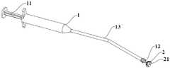
图1为本申请实施例提供的人脑光刺激装置的结构示意图;FIG. 1 is a schematic structural diagram of a human brain light stimulation device provided in an embodiment of the present application;
图2为本申请实施例提供的人脑光刺激装置的爆炸视图;Figure 2 is an exploded view of the human brain light stimulation device provided by the embodiment of the present application;
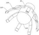
图3为本申请实施例提供的人脑光刺激装置中植入机构的结构示意图;Fig. 3 is a schematic structural diagram of the implantation mechanism in the human brain light stimulation device provided by the embodiment of the present application;
图4为本申请实施例提供的人脑光刺激装置中植入机构的第一种结构示意图;Fig. 4 is a schematic diagram of the first structure of the implant mechanism in the human brain light stimulation device provided by the embodiment of the present application;
图5为本申请实施例提供的人脑光刺激装置中植入机构的第二种结构示意图;Fig. 5 is a schematic diagram of the second structure of the implant mechanism in the human brain light stimulation device provided by the embodiment of the present application;
图6为本申请实施例提供的人脑光刺激装置中植入机构的第三种结构示意图Figure 6 is a schematic diagram of the third structure of the implant mechanism in the human brain light stimulation device provided by the embodiment of the present application
图7为本申请实施例提供的人脑光刺激系统中元器件信号传输的结构框图;Fig. 7 is a structural block diagram of signal transmission of components in the human brain light stimulation system provided by the embodiment of the present application;
图中:1、输送机构;11、活塞杆;111、卡槽;12、推杆;121、卡块;13、导向件;131、空筒;132、柔性软管;2、植入机构;21、外壳;211、容腔;212、透光壳体;213、夹爪;214、弹片;22、光源;221、光源罩;23、电源;24、控制模块;3、摄像头;4、通讯模块;5、上位机;51、处理模块;52、显示模块。In the figure: 1, conveying mechanism; 11, piston rod; 111, slot; 12, push rod; 121, block; 13, guide; 131, empty tube; 132, flexible hose; 2, implant mechanism; 21. Shell; 211. Cavity; 212. Light-transmitting shell; 213. Gripper; 214. Shrapnel; 22. Light source; 221. Light source cover; 23. Power supply; 24. Control module; 3. Camera; 4. Communication module; 5. upper computer; 51. processing module; 52. display module.
具体实施方式Detailed ways
下面将结合本申请实施例中的附图,对本申请实施例中的技术方案进行清楚、完整地描述。显然,所描述的实施例仅仅是本申请一部分实施例,而不是全部的实施例。基于本申请中的实施例,本领域技术人员在没有作出创造性劳动前提下所获得的所有其他实施例,都属于本申请保护的范围。The technical solutions in the embodiments of the present application will be clearly and completely described below in conjunction with the drawings in the embodiments of the present application. Apparently, the described embodiments are only some of the embodiments of this application, not all of them. Based on the embodiments in this application, all other embodiments obtained by those skilled in the art without making creative efforts belong to the scope of protection of this application.
本申请实施例提供一种人脑光刺激装置及其系统,以解决现有中枢神经系统变性疾病治疗中,需要对脑部进行开颅手术,操作比较繁琐,且费用高昂的问题。以下将结合附图对进行说明。The embodiment of the present application provides a human brain photo-stimulation device and its system to solve the problem that in the existing treatment of central nervous system degenerative diseases, it is necessary to perform craniotomy on the brain, and the operation is cumbersome and expensive. It will be described below in conjunction with the accompanying drawings.
如图1所示,本申请实施例提供一种人脑光刺激装置,图1为人脑光刺激装置的结构示意图,其中,人脑光刺激装置可应用在各类中枢神经系统变性疾病中,以帕金森病患者为例,这种人脑光刺激装置能够像向患者的大脑深处发射近红外光,近红外光是一种介于可见光和中红外光之间的电磁波,例如,波长为670nm的近红外光能够激活细胞色素c氧化酶等光感受器,从而调节人体代谢。因此,近红外光能够在人体的各组织间透射,可穿过颅内组织,并到达大脑深处;到达大脑深处的近红外光能够对中枢神经系统产生刺激,并调节患者新陈代谢,保护患者的中枢神经系统,从而避免患者出现帕金森症状,具有快速且稳定的治疗效果。As shown in Figure 1, the embodiment of the present application provides a human brain light stimulation device, Figure 1 is a schematic structural diagram of the human brain light stimulation device, wherein the human brain light stimulation device can be applied to various degenerative diseases of the central nervous system, to For patients with Parkinson's disease, this human brain light stimulation device can emit near-infrared light into the depths of the patient's brain. Near-infrared light is an electromagnetic wave between visible light and mid-infrared light, for example, with a wavelength of 670nm Near-infrared light can activate photoreceptors such as cytochrome c oxidase, thereby regulating human metabolism. Therefore, near-infrared light can be transmitted between various tissues of the human body, can pass through intracranial tissue, and reach the depths of the brain; the near-infrared light that reaches the depths of the brain can stimulate the central nervous system, regulate the patient's metabolism, and protect the patient. The central nervous system, thereby avoiding Parkinson's symptoms in patients, has a rapid and stable therapeutic effect.
如图1-3所示,在一些实施方式中,图2为人脑光刺激装置的爆炸视图,图3为人脑光刺激装置中植入机构2的结构示意图;人脑光刺激装置包括输送机构1和植入机构2;其中,输送机构1包括活塞杆11、推杆12和导向件13,活塞杆11的输出端连接推杆12的输入端,导向件13的中间设有通孔,推杆12的输出端从导向件13的通孔中穿出;植入机构2包括外壳21、光源22、电源23和控制模块24,外壳21的内部设有容腔211,控制模块24和电源23均连接在容腔211的内壁上,光源22与控制模块24电连接,电源23的输出端分别电连接光源22和控制模块24;外壳21的一端与推杆12的输出端可拆卸式连接,外壳21的另一端用于连接在蝶窦内腔壁上;植入机构2的最大截面尺寸大于推杆12输出端的通孔截面尺寸;通过光源22能够向大脑的方向发射近红外光,近红外光可以穿过颅内组织到达大脑深处。As shown in Figures 1-3, in some embodiments, Figure 2 is an exploded view of the human brain light stimulation device, and Figure 3 is a schematic structural view of the implant mechanism 2 in the human brain light stimulation device; the human brain light stimulation device includes a delivery mechanism 1 And implant mechanism 2; Wherein, delivery mechanism 1 comprises piston rod 11, push rod 12 and guide 13, the output end of piston rod 11 connects the input end of push rod 12, and the center of guide 13 is provided with through hole, push rod The output end of 12 passes through the through hole of guide member 13; Implantation mechanism 2 comprises casing 21, light source 22, power supply 23 and control module 24, and the interior of casing 21 is provided with chamber 211, and control module 24 and power supply 23 are all Connected to the inner wall of the cavity 211, the light source 22 is electrically connected to the control module 24, and the output ends of the power supply 23 are respectively electrically connected to the light source 22 and the control module 24; one end of the housing 21 is detachably connected to the output end of the push rod 12, and the housing The other end of 21 is used to connect to the inner wall of the sphenoid sinus; the maximum cross-sectional size of the implant mechanism 2 is larger than the cross-sectional size of the through hole at the output end of the push rod 12; the near-infrared light can be emitted toward the brain through the light source 22, and the near-infrared light Can pass through the intracranial tissue to reach the depths of the brain.
在对患者进行治疗时,可根据患者的症状制定匹配的植入机构2,并将植入机构2装配在输送机构1上,之后将植入机构2放入患者的鼻内,在导向件13的导向下,通过活塞杆11和推杆12将植入机构2输送至患者的蝶窦腔内,然后保持导向件13的所处位置,回拉活塞杆11,活塞杆11通过推杆12带动植入机构2向外运动,由于植入机构2的尺寸大于通孔,因此导向件13的输出端会对植入机构2施加一个反作用力,使得推杆12与植入机构2分离,最终植入机构2掉落在患者的蝶窦腔内,并取出推杆12和导向件13。工作中,植入机构2内的控制模块24能够控制光源22发出近红外光,近红外光可穿过颅内组织到达大脑深处,并对患者大脑深处的中枢神经进行刺激,从而对患者进行治疗。When treating a patient, a matching implant mechanism 2 can be formulated according to the patient's symptoms, and the implant mechanism 2 can be assembled on the delivery mechanism 1, and then the implant mechanism 2 can be put into the patient's nose. Under the guidance of the
在本实施例中,容腔211用于容纳装置的各元器件,能对各元器件起到防护的作用;外壳21的材质可采用非生物降解的聚合物或合金,如聚氨基甲酸酯、不锈钢,钛等材料。外壳21还可采用一体成型结构,将外壳21的头部设计为直径3mm的圆柱状,外壳21的尾部安装有圆柱柄,圆柱柄的底端设有凹槽,推杆12的输出端插接在凹槽内。电源23采用微型电池,微型电池通过微型电源接口为控制模块24和光源22供能。光源22采用直径为1mm的近红外光源,光源22能持续向大脑深处发出波段为650~2500nm的近红外光。In this embodiment, the
如图1-6所示,在上述实施例的基础上,本申请好提供以下实施例,图4为人脑光刺激装置中植入机构2的第一种结构示意图,图5为人脑光刺激装置中植入机构2的第二种结构示意图,图6为人脑光刺激装置中植入机构2的第三种结构示意图。As shown in Figures 1-6, on the basis of the above-mentioned embodiments, the present application provides the following embodiments, Figure 4 is a schematic diagram of the first structure of the implant mechanism 2 in the human brain light stimulation device, and Figure 5 is a human brain light stimulation device The second structure schematic diagram of the implant mechanism 2, Fig. 6 is the third structure schematic diagram of the implant mechanism 2 in the human brain light stimulation device.
在一个实施例中,外壳21包括透光壳体212、夹爪213和弹片214,容腔211设在透光壳体212的内部,夹爪213通过弹片214连接在透光壳体212的外壁上,夹爪213的底端插接在推杆12的输出端,夹爪213部分穿入导向件13的通孔内;光源22的外壁上连接有光源罩221,所述光源罩221用于汇聚光线或发散光线。输送机构1与植入机构2装配时,夹爪213部分放置在导向件13的通孔内,夹爪213会收到在通孔内壁的挤压,此时弹片214处于压缩状态,且透光壳体212上的夹爪213处于收缩状态;植入机构2掉落在蝶窦腔后,弹片214恢复形变,夹爪213在蝶窦腔中展开状态,并贴合在蝶窦内腔壁上,控制模块24控制光源22发射近红外光,近红外光能从透光壳体212透射至蝶窦腔内,并穿过颅内组织到达大脑深处。In one embodiment, the
在本实施例中,夹爪213可采用若干个,且均匀分布在透光壳体212底端侧壁上。在具体实施时,可将夹爪213的数目设为八个,且八个夹爪213均匀安装在透光壳体212底端侧壁上,患者蝶窦腔的直径约为8mm,蝶窦口直径约为5mm,可将推杆12输出端的通孔截面尺寸设为4.4mm;则当夹爪213在压缩时,将八个夹爪213围成的截面尺寸设为4.5mm,当夹爪213自然展开时,将八个夹爪213围成的外壳21的截面尺寸设为8.2mm~8.4mm。光源罩221能够固定光源22,并对光源22发出的光线进行聚拢,然后从透光壳体212处发射出;光源罩221能对光源22起到固定的效果,光源罩221的材质可采用具有反光性能的金属或合金,还可将光源罩221的透光面加工成镜面,根据具体使用场景,光源罩221能对近红外光进行汇聚光线或发散光线,从而保证其透射效果以及使用性能。壳体212的材质可采用聚甲基丙烯酸甲酯,能够保证光源22的透射效果。In this embodiment, several clamping
其中,还可在夹爪213的外壁上嵌入摄像头和信号发射接收器,在导向件13输出端的通孔内安装角度调节器,摄像头连接信号发射接收器,信号发射接收器连接控制模块24和外部终端,角度调节器连接控制模块;当植入机构2掉落之前,角度调节器能够调节植入机构2的旋转角度,使光源22正好对准大脑深处,植入机构2掉落之后,摄像头能够采集光源22发射到蝶窦内腔壁上的光线信息,并将采集的光线信息通过信号发射接收器发射至外部终端,外部终端能够对采集的光线信息进行分析,判断光源22已经对准大脑深处,并向信号发射接收器发送控制指令,信号发射接收器将控制指令传输给控制模块24,控制模块24控制角度调节器来调节夹爪213的抵接位置,使得光源22对准大脑深处,能够改善治疗效果;与此同时,光源罩221能够对光源22发出的光线进一步聚光,从而使光线能更集中射入到大脑深处,提高了患者的治疗效果。Wherein, camera and signal transmitting receiver can also be embedded on the outer wall of
另外,夹爪213还可采用四个C型结构,且均匀围绕在透光壳体212底端侧壁上。当植入机构2送至蝶窦腔后,医生可通过活塞杆11将植入机构2推出,使各夹爪213展开,并抵接在蝶窦内腔壁上;还可在夹爪213的外表面进行磨砂处理,可增加夹爪213与蝶窦内腔壁之间的摩擦力,从而防止植入机构2发生位置移动。In addition, the clamping
如图4-6所示,在本实施例中,夹爪213的展开方向可以是朝向光源22的方向,也可以是朝向推杆12的方向,还可以是朝向其他的安装方向,本申请在此不做限制。As shown in Figures 4-6, in this embodiment, the unfolding direction of the
如图1-3所示,在一个实施例中,导向件13包括空筒131和柔性软管132,空筒131的输出端连接柔性软管132的输入端,空筒131和柔性软管132的中间均设有通孔,推杆12的输出端从空筒131的输入端穿入,推杆12的输出端依次从空筒131的通孔中和柔性软管132的通孔中穿出;柔性软管132的输出端设有开口,夹爪213部分放置在开口内;夹爪213的外壁上设有凸起,凸起抵接在开口的内壁上;活塞杆11的输出端外壁上设有卡槽111,推杆12的输入端外壁上设有卡块121,卡块121卡接在卡槽111内。As shown in Figures 1-3, in one embodiment, the
使用时,将推杆12输入端的卡块121卡接在活塞杆11输出端外壁上的卡槽111中,将推杆12输出端依次从空筒131的通孔和柔性软管132的通孔中穿出,并将植入机构2插接在推杆12的输出端,植入机构2中夹爪213部分放置在柔性软管132的通孔中,使夹爪213上的凸起抵接在开口的内壁上;然后在空筒131和柔性软管132的导向下,使推杆12的输出端以及植入机构2伸入至患者蝶窦腔内;之后,将活塞杆11进行回拉,由于植入机构2的最大截面尺寸小于开口的尺寸,则植入机构2会在开口与推杆12发生分离;最后,通过控制模块24控制光源22发射近红外光,近红外光能穿过蝶窦内腔壁以及颅内组织并到达大脑深处,近红外光能对患者大脑深处的中枢神经进行刺激,从而对患者实现治疗效果。When in use, snap the
如图1-3所示,在一个实施例中,外壳21包括透光壳体212、夹爪213和伸缩杆,容腔211设在透光壳体212的内部,夹爪213的内壁通过伸缩杆连接在透光壳体212的外壁上,夹爪213的底端插接在推杆12的输出端,伸缩杆电连接控制模块24,夹爪213部分穿入导向件13的通孔内。As shown in Figures 1-3, in one embodiment, the
在本实施例中,伸缩杆可采用电动伸缩杆;植入机构2掉落在蝶窦腔之前,电动伸缩杆以及夹爪213处于收缩状态,且安装在推杆12的输出端处,当植入机构2掉落在蝶窦腔后,控制模块24根据患者蝶窦腔的尺寸控制电动伸缩杆伸长,电动伸缩杆能够促使夹爪213展开,使夹爪213抵接在患者蝶窦内腔壁上,从而避免植入机构2在患者蝶窦腔内发生位置滑动。In this embodiment, the telescopic rod can be an electric telescopic rod; before the implant mechanism 2 falls into the sphenoid sinus cavity, the electric telescopic rod and the
如图1、2、3、7所示,图7为人脑光刺激系统中元器件信号传输的结构框图;本申请实施例还提供一种人脑光刺激系统,包括上述实施例中的人脑光刺激装置、摄像头3、通讯模块4和上位机5;其中,可将摄像头3连接在夹爪213的外壁上,摄像头3能够采集蝶窦内腔的图像信息;通讯模块4连接在外壳21的内壁上,通讯模块4电连接控制模块24和摄像头3,通讯模块4能够将蝶窦内腔的图像信息向外界传输;上位机5设在人脑外部,上位机5无线连接通讯模块4,上位机5能够接收蝶窦内腔的图像信息,并根据蝶窦内腔的图像信息来反馈控制指令,通讯模块4接收到上位机5发送的控制指令后,通讯模块4可将控制指令传输给控制模块24,控制模块24能够根据指令来调节人脑光刺激装置中光源22的波长,不同波长的红外光能根据患者的不同症状进行适宜性治疗,从而使患者达到最佳的治疗效果;电源23能够为摄像头3和通讯模块4提供电能。As shown in Figures 1, 2, 3, and 7, Figure 7 is a structural block diagram of the signal transmission of components in the human brain light stimulation system; the embodiment of the present application also provides a human brain light stimulation system, including the human brain light stimulation system in the above embodiment Light stimulation device,
在本实施例中,上位机5包括处理模块51和显示模块52,处理模块51无线连接通讯模块4,通讯模块4电连接显示模块52。In this embodiment, the
使用时,将推杆12输入端的卡块121卡接在活塞杆11输出端外壁上的卡槽111中,将推杆12输出端依次从空筒131的通孔和柔性软管132的通孔中穿出,并将植入机构2插接在推杆12的输出端,植入机构2中夹爪213部分穿入柔性软管132的通孔中,使夹爪213上的凸起抵接在开口的内壁上;然后在空筒131和柔性软管132的导向下,使推杆12的输出端以及植入机构2伸入至患者蝶窦腔内;之后,将活塞杆11进行回拉,由于植入机构2的最大截面尺寸小于开口的尺寸,则植入机构2会在开口与推杆12发生分离;最后通过控制模块24控制光源22发射近红外光,近红外光能穿过颅内组织到达大脑深处,并对患者大脑深处的中枢神经进行刺激,从而对患者进行治疗。工作中,摄像头3能够实时采集患者蝶窦内腔的图像信息,蝶窦内腔的图像信息能够通过通讯模块4传输至外界上位机5中,上位机5中的处理模块51能够对接收到的图像信息进行分析,分析之后,处理模块51能向植入机构2中的通讯模块4无线传输控制指令,通讯模块4将控制指令传递给控制模块24,控制模块24对人脑光刺激装置进行适宜性调节,从而提高了患者的治疗效果;与此同时,摄像头3采集的图像信息还可通过通讯模块4无线传输至上位机5中的显示模块52中,从而方便了医生诊断。When in use, snap the
在上述实施例中,对各个实施例的描述都各有侧重,某个实施例中没有详述的部分,可以参见其他实施例的相关描述。In the foregoing embodiments, the descriptions of each embodiment have their own emphases, and for parts not described in detail in a certain embodiment, reference may be made to relevant descriptions of other embodiments.
在本申请的描述中,术语“第一”、“第二”仅用于描述目的,而不能理解为指示或暗示相对重要性或者隐含指明所指示的技术特征的数量。由此,限定有“第一”、“第二”的特征可以明示或者隐含地包括一个或者更多个特征。In the description of the present application, the terms "first" and "second" are used for descriptive purposes only, and cannot be understood as indicating or implying relative importance or implicitly specifying the quantity of indicated technical features. Thus, features defined as "first" and "second" may explicitly or implicitly include one or more features.
以上对本申请实施例所提供的人脑光刺激装置进行了详细介绍,本文中应用了具体个例对本申请的原理及实施方式进行了阐述,以上实施例的说明只是用于帮助理解本申请的方法及其核心思想;同时,对于本领域的技术人员,依据本申请的思想,在具体实施方式及应用范围上均会有改变之处,综上,本说明书内容不应理解为对本申请的限制。The human brain photostimulation device provided by the embodiment of the present application has been introduced in detail above. In this paper, specific examples are used to illustrate the principle and implementation of the present application. The description of the above embodiment is only used to help understand the method of the present application. and its core idea; at the same time, for those skilled in the art, according to the idea of this application, there will be changes in the specific implementation and application scope. In summary, the content of this specification should not be construed as limiting the application.
Claims (10)
Priority Applications (1)
| Application Number | Priority Date | Filing Date | Title |
|---|---|---|---|
| CN202210643624.XACN115245629A (en) | 2022-06-08 | 2022-06-08 | Human brain light stimulation device and system thereof |
Applications Claiming Priority (1)
| Application Number | Priority Date | Filing Date | Title |
|---|---|---|---|
| CN202210643624.XACN115245629A (en) | 2022-06-08 | 2022-06-08 | Human brain light stimulation device and system thereof |
Publications (1)
| Publication Number | Publication Date |
|---|---|
| CN115245629Atrue CN115245629A (en) | 2022-10-28 |
Family
ID=83697819
Family Applications (1)
| Application Number | Title | Priority Date | Filing Date |
|---|---|---|---|
| CN202210643624.XAPendingCN115245629A (en) | 2022-06-08 | 2022-06-08 | Human brain light stimulation device and system thereof |
Country Status (1)
| Country | Link |
|---|---|
| CN (1) | CN115245629A (en) |
Citations (5)
| Publication number | Priority date | Publication date | Assignee | Title |
|---|---|---|---|---|
| US20050203538A1 (en)* | 2004-03-02 | 2005-09-15 | Janzen Lo | Surgical instrument for implants |
| US20060287695A1 (en)* | 2005-06-16 | 2006-12-21 | Dimauro Thomas M | Intranasal red light probe for treating Alzheimer's disease |
| US20070186933A1 (en)* | 2006-01-17 | 2007-08-16 | Pulmonx | Systems and methods for delivering flow restrictive element to airway in lungs |
| CN208015457U (en)* | 2018-03-02 | 2018-10-26 | 江苏伟康洁婧医疗器械股份有限公司 | A kind of implantable medical devices non-contact charger |
| AU2020100961A4 (en)* | 2020-06-08 | 2020-07-16 | Guilin Univ. Electr. Techol. | An optical fiber and system for visualization interventional photodynamic therapy in humans |
- 2022
- 2022-06-08CNCN202210643624.XApatent/CN115245629A/enactivePending
Patent Citations (5)
| Publication number | Priority date | Publication date | Assignee | Title |
|---|---|---|---|---|
| US20050203538A1 (en)* | 2004-03-02 | 2005-09-15 | Janzen Lo | Surgical instrument for implants |
| US20060287695A1 (en)* | 2005-06-16 | 2006-12-21 | Dimauro Thomas M | Intranasal red light probe for treating Alzheimer's disease |
| US20070186933A1 (en)* | 2006-01-17 | 2007-08-16 | Pulmonx | Systems and methods for delivering flow restrictive element to airway in lungs |
| CN208015457U (en)* | 2018-03-02 | 2018-10-26 | 江苏伟康洁婧医疗器械股份有限公司 | A kind of implantable medical devices non-contact charger |
| AU2020100961A4 (en)* | 2020-06-08 | 2020-07-16 | Guilin Univ. Electr. Techol. | An optical fiber and system for visualization interventional photodynamic therapy in humans |
Similar Documents
| Publication | Publication Date | Title |
|---|---|---|
| EP4168110B1 (en) | Stimulation systems with a lens arrangement for light coupling | |
| EP2189183A1 (en) | Apparatus for sublingual application of light to blood | |
| US20110190689A1 (en) | Intravaginal therapy device | |
| CN106232045B (en) | Apparatus and method for photodynamic therapy | |
| US20070203550A1 (en) | Method and apparatus for application of light to tissue | |
| CN108143477B (en) | Intramedullary bone lengthening device using memory alloy spring electromagnetic heating | |
| EP1940502A2 (en) | Method and apparatus for providing light to blood | |
| EP2243514A1 (en) | Method and apparatus for the combined application of light therapy, optic diagnosis and fluid to tissue | |
| CN115245629A (en) | Human brain light stimulation device and system thereof | |
| KR101515721B1 (en) | Apparatus for curing prostate diseases | |
| WO2007040702A2 (en) | Method and apparatus for sublingual application of light to blood | |
| CN108671415A (en) | A kind of medical optical fiber and laser therapeutic apparantus | |
| JP7250904B2 (en) | modular implantable medical device | |
| CN111568348A (en) | Optical diagnosis and treatment capsule endoscope with external power supply and control | |
| KR100550604B1 (en) | Prostate Physical Therapy | |
| US12364876B2 (en) | Device and method for treating dry eyes | |
| CN109939360A (en) | A kind of hand-held Terahertz life physiotherapy equipment | |
| AU2021412498B2 (en) | Device and method for treating dry eyes | |
| KR101525608B1 (en) | Inserting apparatus for diagnosing and curing prostate diseases | |
| US20230173260A1 (en) | Electrode wire for applying electrical stimulation to body organs, and electrode system using same | |
| KR200352431Y1 (en) | Physical therapy device for the prostate | |
| CN116159247A (en) | Nerve stimulation system and control method thereof | |
| WO2024231915A1 (en) | Device and method for treating dry eyes | |
| CN204352377U (en) | A kind of phototherapy nasal cavity therapeutic instrument | |
| WO2021223702A1 (en) | Cranial nerve regulator |
Legal Events
| Date | Code | Title | Description |
|---|---|---|---|
| PB01 | Publication | ||
| PB01 | Publication | ||
| SE01 | Entry into force of request for substantive examination | ||
| SE01 | Entry into force of request for substantive examination | ||
| TA01 | Transfer of patent application right | Effective date of registration:20240228 Address after:430000 East Lake New Technology Development Zone, Wuhan City, Hubei Province, 818 High-tech Avenue, No. 4, 4th Floor, 7th Building, B District, High-tech Medical Device Park Applicant after:Wuhan Zilian Hongkang Technology Co.,Ltd. Country or region after:China Address before:3F-325, Building 9, SBI Chuangye Street, Optics Valley, Donghu New Technology Development Zone, Wuhan City, Hubei Province 430000 (Free Trade Zone Wuhan Area) Applicant before:Wuhan aiketais Medical Technology Co.,Ltd. Country or region before:China | |
| TA01 | Transfer of patent application right | ||
| TA01 | Transfer of patent application right | Effective date of registration:20250917 Address after:No.16, Fenghuangyuan Middle Road, Donghu New Technology Development Zone, Wuhan, Hubei 430000 Applicant after:WUHAN YIRUIDE MEDICAL EQUIPMENT Co.,Ltd. Country or region after:China Address before:430000 East Lake New Technology Development Zone, Wuhan City, Hubei Province, 818 High-tech Avenue, No. 4, 4th Floor, 7th Building, B District, High-tech Medical Device Park Applicant before:Wuhan Zilian Hongkang Technology Co.,Ltd. Country or region before:China |