CN115245332A - Electronic equipment, paster and detecting system - Google Patents
Electronic equipment, paster and detecting systemDownload PDFInfo
- Publication number
- CN115245332A CN115245332ACN202110461872.8ACN202110461872ACN115245332ACN 115245332 ACN115245332 ACN 115245332ACN 202110461872 ACN202110461872 ACN 202110461872ACN 115245332 ACN115245332 ACN 115245332A
- Authority
- CN
- China
- Prior art keywords
- electrode
- interface
- patch
- electronic device
- magnetic
- Prior art date
- Legal status (The legal status is an assumption and is not a legal conclusion. Google has not performed a legal analysis and makes no representation as to the accuracy of the status listed.)
- Granted
Links
Images


Classifications
- A—HUMAN NECESSITIES
- A61—MEDICAL OR VETERINARY SCIENCE; HYGIENE
- A61B—DIAGNOSIS; SURGERY; IDENTIFICATION
- A61B5/00—Measuring for diagnostic purposes; Identification of persons
- A61B5/145—Measuring characteristics of blood in vivo, e.g. gas concentration or pH-value ; Measuring characteristics of body fluids or tissues, e.g. interstitial fluid or cerebral tissue
- A61B5/1468—Measuring characteristics of blood in vivo, e.g. gas concentration or pH-value ; Measuring characteristics of body fluids or tissues, e.g. interstitial fluid or cerebral tissue using chemical or electrochemical methods, e.g. by polarographic means
- A61B5/1473—Measuring characteristics of blood in vivo, e.g. gas concentration or pH-value ; Measuring characteristics of body fluids or tissues, e.g. interstitial fluid or cerebral tissue using chemical or electrochemical methods, e.g. by polarographic means invasive, e.g. introduced into the body by a catheter
- A—HUMAN NECESSITIES
- A61—MEDICAL OR VETERINARY SCIENCE; HYGIENE
- A61B—DIAGNOSIS; SURGERY; IDENTIFICATION
- A61B5/00—Measuring for diagnostic purposes; Identification of persons
- A61B5/0002—Remote monitoring of patients using telemetry, e.g. transmission of vital signals via a communication network
- A61B5/0015—Remote monitoring of patients using telemetry, e.g. transmission of vital signals via a communication network characterised by features of the telemetry system
- A61B5/002—Monitoring the patient using a local or closed circuit, e.g. in a room or building
- A—HUMAN NECESSITIES
- A61—MEDICAL OR VETERINARY SCIENCE; HYGIENE
- A61B—DIAGNOSIS; SURGERY; IDENTIFICATION
- A61B5/00—Measuring for diagnostic purposes; Identification of persons
- A61B5/145—Measuring characteristics of blood in vivo, e.g. gas concentration or pH-value ; Measuring characteristics of body fluids or tissues, e.g. interstitial fluid or cerebral tissue
- A61B5/14507—Measuring characteristics of blood in vivo, e.g. gas concentration or pH-value ; Measuring characteristics of body fluids or tissues, e.g. interstitial fluid or cerebral tissue specially adapted for measuring characteristics of body fluids other than blood
- A61B5/1451—Measuring characteristics of blood in vivo, e.g. gas concentration or pH-value ; Measuring characteristics of body fluids or tissues, e.g. interstitial fluid or cerebral tissue specially adapted for measuring characteristics of body fluids other than blood for interstitial fluid
- A61B5/14514—Measuring characteristics of blood in vivo, e.g. gas concentration or pH-value ; Measuring characteristics of body fluids or tissues, e.g. interstitial fluid or cerebral tissue specially adapted for measuring characteristics of body fluids other than blood for interstitial fluid using means for aiding extraction of interstitial fluid, e.g. microneedles or suction
- A—HUMAN NECESSITIES
- A61—MEDICAL OR VETERINARY SCIENCE; HYGIENE
- A61B—DIAGNOSIS; SURGERY; IDENTIFICATION
- A61B5/00—Measuring for diagnostic purposes; Identification of persons
- A61B5/145—Measuring characteristics of blood in vivo, e.g. gas concentration or pH-value ; Measuring characteristics of body fluids or tissues, e.g. interstitial fluid or cerebral tissue
- A61B5/14532—Measuring characteristics of blood in vivo, e.g. gas concentration or pH-value ; Measuring characteristics of body fluids or tissues, e.g. interstitial fluid or cerebral tissue for measuring glucose, e.g. by tissue impedance measurement
- A—HUMAN NECESSITIES
- A61—MEDICAL OR VETERINARY SCIENCE; HYGIENE
- A61B—DIAGNOSIS; SURGERY; IDENTIFICATION
- A61B5/00—Measuring for diagnostic purposes; Identification of persons
- A61B5/145—Measuring characteristics of blood in vivo, e.g. gas concentration or pH-value ; Measuring characteristics of body fluids or tissues, e.g. interstitial fluid or cerebral tissue
- A61B5/14542—Measuring characteristics of blood in vivo, e.g. gas concentration or pH-value ; Measuring characteristics of body fluids or tissues, e.g. interstitial fluid or cerebral tissue for measuring blood gases
- A—HUMAN NECESSITIES
- A61—MEDICAL OR VETERINARY SCIENCE; HYGIENE
- A61B—DIAGNOSIS; SURGERY; IDENTIFICATION
- A61B5/00—Measuring for diagnostic purposes; Identification of persons
- A61B5/68—Arrangements of detecting, measuring or recording means, e.g. sensors, in relation to patient
- A61B5/6801—Arrangements of detecting, measuring or recording means, e.g. sensors, in relation to patient specially adapted to be attached to or worn on the body surface
- A61B5/6802—Sensor mounted on worn items
- A61B5/681—Wristwatch-type devices
- A—HUMAN NECESSITIES
- A61—MEDICAL OR VETERINARY SCIENCE; HYGIENE
- A61B—DIAGNOSIS; SURGERY; IDENTIFICATION
- A61B5/00—Measuring for diagnostic purposes; Identification of persons
- A61B5/68—Arrangements of detecting, measuring or recording means, e.g. sensors, in relation to patient
- A61B5/6801—Arrangements of detecting, measuring or recording means, e.g. sensors, in relation to patient specially adapted to be attached to or worn on the body surface
- A61B5/683—Means for maintaining contact with the body
- A61B5/6832—Means for maintaining contact with the body using adhesives
- A61B5/6833—Adhesive patches
- A—HUMAN NECESSITIES
- A61—MEDICAL OR VETERINARY SCIENCE; HYGIENE
- A61B—DIAGNOSIS; SURGERY; IDENTIFICATION
- A61B5/00—Measuring for diagnostic purposes; Identification of persons
- A61B5/68—Arrangements of detecting, measuring or recording means, e.g. sensors, in relation to patient
- A61B5/6846—Arrangements of detecting, measuring or recording means, e.g. sensors, in relation to patient specially adapted to be brought in contact with an internal body part, i.e. invasive
- A61B5/6847—Arrangements of detecting, measuring or recording means, e.g. sensors, in relation to patient specially adapted to be brought in contact with an internal body part, i.e. invasive mounted on an invasive device
- A61B5/685—Microneedles
Landscapes
- Health & Medical Sciences (AREA)
- Life Sciences & Earth Sciences (AREA)
- Physics & Mathematics (AREA)
- Engineering & Computer Science (AREA)
- Surgery (AREA)
- Public Health (AREA)
- Biomedical Technology (AREA)
- Heart & Thoracic Surgery (AREA)
- Medical Informatics (AREA)
- Molecular Biology (AREA)
- Biophysics (AREA)
- Animal Behavior & Ethology (AREA)
- General Health & Medical Sciences (AREA)
- Pathology (AREA)
- Veterinary Medicine (AREA)
- Optics & Photonics (AREA)
- Chemical & Material Sciences (AREA)
- Chemical Kinetics & Catalysis (AREA)
- General Chemical & Material Sciences (AREA)
- Emergency Medicine (AREA)
- Computer Networks & Wireless Communication (AREA)
- Measurement Of The Respiration, Hearing Ability, Form, And Blood Characteristics Of Living Organisms (AREA)
Abstract
Description
Translated fromChinese技术领域technical field
本申请涉及电子技术领域,尤其涉及一种电子设备、贴片及检测系统。The present application relates to the field of electronic technology, and in particular, to an electronic device, a patch and a detection system.
背景技术Background technique
当今,世界范围内的糖尿病患者数量急剧上升,糖尿病及其并发症给人类健康和社会发展带来了沉重负担。Today, the number of diabetic patients worldwide is rising sharply, and diabetes and its complications have brought a heavy burden to human health and social development.
为了给糖尿病患者提供更加方便的血糖检测方式,便携式或穿戴式血糖检测产品应运而生。通常,血糖检测产品包括采血针、血糖仪和试纸条。用户在使用时,首先用采血针在指尖部位破皮,获取指尖血;之后用试纸条蘸取少量血液;最后将试纸条插入血糖仪,经过十秒钟左右,血糖仪的屏幕上显示血糖浓度。这种血糖检测产品通常无法连续检测血糖,并且每次测量都需要扎破手指,为患者带来痛苦。In order to provide diabetic patients with a more convenient way of blood sugar testing, portable or wearable blood sugar testing products have emerged as the times require. Typically, blood glucose testing products include lancets, blood glucose meters, and test strips. When the user is using, first use a blood collection needle to break the skin at the fingertip to obtain fingertip blood; then use a test strip to dip a small amount of blood; finally insert the test strip into the blood glucose meter. After about ten seconds, the screen of the blood glucose meter will be displayed. The blood sugar level is displayed on the display. Such blood glucose monitoring products typically cannot measure blood glucose continuously, and each measurement requires a finger prick, causing pain to the patient.
目前,一种血糖检测产品包括贴片和读写器。其中,贴片上包含一根针状的葡萄糖传感电极,以及恒电位仪电路模块、数据处理模块、传输模块。其中,贴片可以佩戴于人体,进行血糖检测。这种血糖检测产品能够实现连续检测血糖,并且不必每次测量都需要扎破手指。然而,这种贴片的葡萄糖传感电极需要置入人体皮肤,为避免葡萄糖传感电极长期置入皮肤造成感染(或葡萄糖传感电极正常使用失效),因此贴片贴敷在患者腹部后通常有一定的使用期限,例如,最多3到5日需要更换。因此作为一种耗材,贴片上同时集成葡萄糖传感电极,以及恒电位仪电路模块、数据处理模块、传输模块;造成贴片的结构较为复杂,提高了使用成本。Currently, a blood glucose testing product includes a patch and a reader. Among them, the patch includes a needle-shaped glucose sensing electrode, as well as a potentiostat circuit module, a data processing module, and a transmission module. Among them, the patch can be worn on the human body for blood sugar detection. This blood sugar monitoring product enables continuous blood sugar detection without having to prick your finger every time you measure. However, the glucose sensing electrodes of this patch need to be inserted into the human skin. In order to avoid infection caused by long-term insertion of the glucose sensing electrodes into the skin (or failure of normal use of the glucose sensing electrodes), the patch is usually applied to the abdomen of the patient. There is a certain period of use, for example, a maximum of 3 to 5 days needs to be replaced. Therefore, as a consumable material, the patch integrates glucose sensing electrodes, as well as a potentiostat circuit module, a data processing module, and a transmission module, resulting in a more complex structure of the patch, which increases the cost of use.
发明内容SUMMARY OF THE INVENTION
本申请实施例提供一种电子设备、贴片及检测系统,能够简化贴片的结构,降低使用成本。The embodiments of the present application provide an electronic device, a patch, and a detection system, which can simplify the structure of the patch and reduce the use cost.
为达到上述目的,本申请采用如下技术方案:To achieve the above object, the application adopts the following technical solutions:
第一方面,提供一种检测系统。该检测系统用于检测生理参数,例如,血糖、血脂、血氧等生理参数。该检测系统包括贴片和电子设备;其中,该贴片包括:基底、第一电极接口、黏胶层以及第一微针;该第一电极接口设置在基底的第一表面上;胶黏层设置在基底的第二表面上,第二表面背向于第一表面;第一微针设置在基底的第二表面上;其中,第一微针上设置有第一电极,第一电极与第一电极接口耦合;该电子设备包括:电化学传感电路以及第一外接接口;第一外接接口设置在电子设备的背面,其中第一外接接口与电化学传感电路耦合;其中,电子设备的背面朝向人体佩戴时,第一外接接口与第一电极接口电连接,并在贴片和电子设备之间传输电信号。这样,将贴片贴敷于人体时,第一微针刺入人体的真皮,这样使得第一电极可以与真皮的血液相接触;当电子设备佩戴于人体(例如腕部)时,电子设备上的第一外接接口与贴片的第一电极接口形成电连接;贴片和电子设备之间可以传输电信号;这样,在血液中的成分(例如葡萄糖、氧气、血脂等)在第一电极上产生电化学反应,形成电信号时,使得电子设备上与第一外接接口连接的电化学传感电路能够检测到电化学反应形成的电信号,进而将电信号转换为检测信号实现生理参数的检测。这样,由于不在贴片上设置诸如电化学传感电路、数据处理模块、传输模块等电路模块,简化了贴片的结构,从而降低了使用成本。In a first aspect, a detection system is provided. The detection system is used to detect physiological parameters, such as blood glucose, blood lipids, blood oxygen and other physiological parameters. The detection system includes a patch and an electronic device; wherein, the patch includes: a substrate, a first electrode interface, an adhesive layer and a first microneedle; the first electrode interface is arranged on the first surface of the substrate; the adhesive layer arranged on the second surface of the substrate, the second surface facing away from the first surface; the first microneedle is arranged on the second surface of the substrate; wherein, the first microneedle is provided with a first electrode, and the first electrode and the An electrode interface is coupled; the electronic device includes: an electrochemical sensing circuit and a first external interface; the first external interface is arranged on the back of the electronic device, wherein the first external interface is coupled with the electrochemical sensing circuit; When the back is facing the human body, the first external interface is electrically connected with the first electrode interface, and transmits electrical signals between the patch and the electronic device. In this way, when the patch is applied to the human body, the first microneedle pierces the dermis of the human body, so that the first electrode can be in contact with the blood of the dermis; when the electronic device is worn on the human body (for example, the wrist), on the electronic device The first external interface of the device forms an electrical connection with the first electrode interface of the patch; electrical signals can be transmitted between the patch and the electronic device; in this way, the components in the blood (such as glucose, oxygen, blood lipids, etc.) are on the first electrode When an electrochemical reaction is generated and an electrical signal is formed, the electrochemical sensing circuit connected to the first external interface on the electronic device can detect the electrical signal formed by the electrochemical reaction, and then convert the electrical signal into a detection signal to realize the detection of physiological parameters. . In this way, since circuit modules such as an electrochemical sensing circuit, a data processing module, a transmission module and the like are not arranged on the patch, the structure of the patch is simplified, thereby reducing the use cost.
在一种可能的实现方式中,该第一微针上还设置有第二电极,该贴片还包括:第二电极接口,第二电极接口设置在基底的第一表面上;其中,第二电极与第二电极接口耦合;电子设备还包括第二外接接口,第二外接接口设置在电子设备的背面,其中第二外接接口与电化学传感电路耦合;其中,电子设备的背面朝向人体佩戴时,第二外接接口与第二电极接口电连接,并在贴片和电子设备之间传输电信号。其中,对于不同的生理参数的检测,可能需要通过一个或多个电极实现,此时可以在第一微针上设置一个或多个电极。例如对于血糖检测,可以在第一微针上设置两个不同的电极,例如,第一电极和第二电极,并且第一电极和第二电极可以分别为工作电极、参比电极。当然,对于血糖检测,也可以在第一微针上设置三个电极,例如还可以设置对电极。In a possible implementation manner, the first microneedle is further provided with a second electrode, and the patch further includes: a second electrode interface, the second electrode interface is provided on the first surface of the substrate; wherein the second electrode interface is The electrode is coupled with the second electrode interface; the electronic device further includes a second external interface, the second external interface is arranged on the back of the electronic device, wherein the second external interface is coupled with the electrochemical sensing circuit; wherein, the back of the electronic device is worn towards the human body When , the second external interface is electrically connected with the second electrode interface, and transmits electrical signals between the patch and the electronic device. Wherein, the detection of different physiological parameters may need to be realized by one or more electrodes, and in this case, one or more electrodes may be arranged on the first microneedle. For example, for blood glucose detection, two different electrodes, eg, a first electrode and a second electrode, may be provided on the first microneedle, and the first electrode and the second electrode may be a working electrode and a reference electrode, respectively. Of course, for blood sugar detection, three electrodes may also be provided on the first microneedle, for example, a counter electrode may also be provided.
在一种可能的实现方式中,该贴片还包括:第二微针和第二电极接口;第二微针设置在基底的第二表面上;第二电极接口设置在基底的第一表面上;其中,第二微针上设置有第二电极,第二电极与第二电极接口耦合;电子设备还包括第二外接接口,第二外接接口设置在电子设备的背面,其中第二外接接口与电化学传感电路耦合;其中,电子设备的背面朝向人体佩戴时,第二外接接口与第二电极接口电连接,并在贴片和电子设备之间传输电信号。其中,对于不同的生理参数的检测,可能需要通过一个或多个电极实现,此时可以设置多个微针,例如设置在基底的第二表面上第二微针,并在第二微针上设置第二电极;例如对于血糖检测,可以在第一微针上设置第一电极,在第二微针上设置第二电极,并且第一电极和第二电极不同,例如第一电极和第二电极可以分别为工作电极、参比电极。当然,对于血糖检测,贴片还可以包括对电极,该对电极可以是设置在第一电极或第二电极上,或者该对电极也可以是单独设置在基底的第二表面上第三微针上。In a possible implementation manner, the patch further includes: a second microneedle and a second electrode interface; the second microneedle is arranged on the second surface of the substrate; the second electrode interface is arranged on the first surface of the substrate ; wherein, the second microneedle is provided with a second electrode, and the second electrode is coupled with the second electrode interface; the electronic device also includes a second external interface, the second external interface is arranged on the back of the electronic device, wherein the second external interface and The electrochemical sensing circuit is coupled; wherein, when the back of the electronic device is worn toward the human body, the second external interface is electrically connected to the second electrode interface, and electrical signals are transmitted between the patch and the electronic device. Among them, the detection of different physiological parameters may need to be realized by one or more electrodes. In this case, multiple microneedles can be arranged, for example, the second microneedles are arranged on the second surface of the substrate, and the second microneedles are arranged on the second microneedles. A second electrode is provided; for example, for blood glucose detection, a first electrode can be provided on the first microneedle, a second electrode can be provided on the second microneedle, and the first electrode and the second electrode are different, such as the first electrode and the second electrode The electrodes may be working electrodes and reference electrodes, respectively. Of course, for blood sugar detection, the patch may also include a counter electrode, and the pair of electrodes may be disposed on the first electrode or the second electrode, or the pair of electrodes may also be a third microneedle separately disposed on the second surface of the substrate superior.
在一种可能的实现方式中,第一电极接口以及第二电极接口具有磁性,或者第一电极接口以及第二电极接口为磁性材料;第一外接接口以及第二外接接口具有磁性,或者第一外接接口以及第二外接接口为磁性材料。例如:第一外接接口以及第一电极接口(第二外接接口以及第二电极接口)可以采用钕铁硼、钐钴、铝镍钴以及铁铬钴等磁性材料,并且可以采用磁场对磁性材料磁化使磁性材料具有磁性。为了确保电子设备的第一外接接口与贴片的第一电极接口之间(第二外接接口与贴片的第二电极接口之间)电连接的可靠性,可以采用磁性将第一外接接口以及第一电极接口吸合(将第二外接接口与贴片的第二电极接口吸合)。具体的,第一外接接口以及第一电极接口(第二外接接口以及第二电极接口)可以均具有磁性(例如相反的磁性),或者一者具有磁性,另一者为磁性材料。此外,当第一外接接口以及第一电极接口(第二外接接口以及第二电极接口)均采用磁性材料时,可以在第一外接接口以及第一电极接口(第二外接接口以及第二电极接口)相接触的表面采用电镀或金属沉积等工艺制作一层或多层镍、铜等高导电率的材料,以增加第一外接接口以及第一电极接口(第二外接接口以及第二电极接口)的导电性。这样,由于第一外接接口以及第一电极接口(第二外接接口以及第二电极接口)采用弱磁方式吸合可以确保两者之间电连接的可靠性,当有外力扰动电子设备时,第一外接接口以及第一电极接口(第二外接接口以及第二电极接口)可以脱离,避免电子设备的扰动牵连贴片对人体皮肤划伤。In a possible implementation manner, the first electrode interface and the second electrode interface are magnetic, or the first electrode interface and the second electrode interface are magnetic materials; the first external interface and the second external interface are magnetic, or the first The external interface and the second external interface are made of magnetic materials. For example: the first external interface and the first electrode interface (the second external interface and the second electrode interface) can use magnetic materials such as NdFeB, Samarium Cobalt, AlNiCo and FeCrCo, and can use a magnetic field to magnetize the magnetic materials Make magnetic materials magnetic. In order to ensure the reliability of the electrical connection between the first external interface of the electronic device and the first electrode interface of the patch (between the second external interface and the second electrode interface of the patch), the first external interface and the The first electrode interface is pulled in (the second external interface is pulled in with the second electrode interface of the patch). Specifically, the first external interface and the first electrode interface (the second external interface and the second electrode interface) may both have magnetic properties (eg opposite magnetic properties), or one may be magnetic and the other may be a magnetic material. In addition, when the first external interface and the first electrode interface (the second external interface and the second electrode interface) are both made of magnetic materials, the first external interface and the first electrode interface (the second external interface and the second electrode interface) ) The contacting surface is made of one or more layers of nickel, copper and other high-conductivity materials by electroplating or metal deposition, so as to increase the first external interface and the first electrode interface (the second external interface and the second electrode interface) conductivity. In this way, since the first external interface and the first electrode interface (the second external interface and the second electrode interface) are attracted in a weak magnetic manner, the reliability of the electrical connection between the two can be ensured. An external interface and the first electrode interface (the second external interface and the second electrode interface) can be disengaged, so as to avoid the disturbance of the electronic equipment involving the patch from scratching the human skin.
在一种可能是实现方式中,贴片还包括:挡水条,该挡水条设置在基底的第一表面,其中该挡水条包围第一电极接口。这样,当挡水条与电子设备贴合时,可以在电子设备的背面与基底之间形成密闭的空间,避免水或汗渍等导电液体对第一电极接口的影响,例如,当贴片上设置有第二电极接口时,导电液体可能会将第一电极接口与第二电极接口短路,从而影响生理参数检测的可靠性。In a possible implementation manner, the patch further includes: a water blocking strip, the water blocking strip is disposed on the first surface of the substrate, wherein the water blocking strip surrounds the first electrode interface. In this way, when the water blocking strip is attached to the electronic device, a closed space can be formed between the back of the electronic device and the substrate to avoid the influence of conductive liquids such as water or sweat on the first electrode interface. For example, when the patch is provided with When there is a second electrode interface, the conductive liquid may short-circuit the first electrode interface and the second electrode interface, thereby affecting the reliability of the detection of physiological parameters.
在一种可能是实现方式中,贴片还包括:贴敷标记,该贴敷标记设置在基底的第一表面,贴敷标记用于指示贴片的贴敷方向。例如,在将贴片贴敷至皮肤时,贴敷标记指示朝向无名指和中指之间的方向贴敷。这样确保电子设备上的第一外接接口与贴片的第一电极接口(或者第二外接接口与贴片的第二电极接口)形成正确的连接方式。In a possible implementation manner, the patch further includes: an application mark, the application mark is disposed on the first surface of the substrate, and the application mark is used to indicate the application direction of the patch. For example, when the patch is applied to the skin, the application markings indicate the application in a direction between the ring finger and the middle finger. This ensures that the first external interface on the electronic device and the first electrode interface of the patch (or the second external interface and the second electrode interface of the patch) form a correct connection mode.
在一种可能是实现方式中,第一电极接口和第二电极接口为同心设置的圆环状电极接口;第一外接接口以及第二外接接口为同心设置的圆环状外接接口。可以理解的是,贴片的第一电极接口和第二电极接口为同心设置的圆环状电极接口,对应的电子设备的第一外接接口以及第二外接接口为同心设置的圆环状外接接口时,在垂直于圆环的中心的轴线上,无论如何转动电子设备均不会影响第一外接接口与第一电极接口(或者第二外接接口与第二电极接口)的正常连接。In a possible implementation manner, the first electrode interface and the second electrode interface are concentric annular electrode interfaces; the first external interface and the second external interface are concentric annular external interfaces. It can be understood that the first electrode interface and the second electrode interface of the patch are concentric annular electrode interfaces, and the corresponding first external interface and second external interface of the electronic device are concentric annular external interfaces. When , on the axis perpendicular to the center of the ring, no matter how the electronic device is rotated, the normal connection between the first external interface and the first electrode interface (or the second external interface and the second electrode interface) will not be affected.
在一种可能是实现方式中,第一电极的形状包括:柱状、面状或绕线状。当然,在贴片上具有其他电极时,也可以采用上述的形状。In a possible implementation manner, the shape of the first electrode includes a column shape, a plane shape or a wire shape. Of course, when there are other electrodes on the patch, the above-mentioned shapes can also be used.
在一种可能是实现方式中,第一电极包括以下一种或多种材料:灯黑碳、玻璃碳、石墨、银、氯化银、铂、钯、铂铱合金、钛、金以及铱。当然,在贴片上具有其他电极时,也可以采用上述的材料。尤其,参比电极RE可以采用银或氯化银,由于银或氯化银电极在水溶液体系中具有很小的溶解度、极高的稳定性和可逆性,且即使在有氢存在的情况下电极表面也会得到很好的保护,因此用作参比电极时,可以尽量降低电极自噪声。In one possible implementation, the first electrode includes one or more of the following materials: lamp black carbon, glassy carbon, graphite, silver, silver chloride, platinum, palladium, platinum-iridium alloy, titanium, gold, and iridium. Of course, when there are other electrodes on the patch, the above-mentioned materials can also be used. In particular, silver or silver chloride can be used as the reference electrode RE, because silver or silver chloride electrode has little solubility in aqueous system, high stability and reversibility, and even in the presence of hydrogen The surface is also well protected, so electrode self-noise can be minimized when used as a reference electrode.
在一种可能是实现方式中,为了保证植入快,痛感低,创面小,并且确保微针的长度足够置入皮下。该第一微针的长度为1-5mm,第一微针的直径为7-400μm。当然,在贴片上具有其他微针(例如第二微针)时,也可以采用上述的第一微针的尺寸。In a possible implementation, in order to ensure fast implantation, low pain, small wound surface, and to ensure that the length of the microneedle is sufficient to be placed subcutaneously. The length of the first microneedles is 1-5 mm, and the diameter of the first microneedles is 7-400 μm. Of course, when there are other microneedles (eg, second microneedles) on the patch, the size of the first microneedles described above can also be used.
在一种可能是实现方式中,第一微针的材料包括不锈钢、铂或高分子材料。当然,在贴片上具有其他微针(例如第二微针)时,也可以采用上述的第一微针的材料。In a possible implementation manner, the material of the first microneedle includes stainless steel, platinum or polymer material. Of course, when there are other microneedles (eg, second microneedles) on the patch, the above-mentioned materials of the first microneedles can also be used.
在一种可能是实现方式中,该贴片还包括:第一磁吸接口,第一磁吸接口设置在基底的第一表面;第一磁吸接口具有磁性,或者第一磁吸接口为磁性材料;电子设备还包括:设置在电子设备的背面的第二磁吸接口,第二磁吸接口具有磁性,或者第二磁吸接口为磁性材料;当电子设备的背面朝向人体佩戴时,第一磁吸接口与第二磁吸接口吸合。例如:可以在贴片的基底的第一表面设置第一磁吸接口,第一磁吸接口具有磁性,或者第一磁吸接口为磁性材料。在电子设备设置第二磁吸接口,第二磁吸接口具有磁性,或者第二磁吸接口为磁性材料。其中第二磁吸接口的一面漏出电子设备。具体的,第一磁吸接口以及第二磁吸接口可以均具有磁性(例如相反的磁性),或者一者具有磁性,另一者为磁性材料。第一磁吸接口与第二磁吸接口的位置一一对应,并且通过第一磁吸接口与第二磁吸接口将电子设备以及贴片吸合后,第一外接接口与第一电极接口(第二外接接口与第二电极接口)电连接。In a possible implementation manner, the patch further includes: a first magnetic attraction interface, the first magnetic attraction interface is disposed on the first surface of the substrate; the first magnetic attraction interface is magnetic, or the first magnetic attraction interface is magnetic material; the electronic device further includes: a second magnetic interface disposed on the back of the electronic device, the second magnetic interface is magnetic, or the second magnetic interface is a magnetic material; when the back of the electronic device is worn towards the human body, the first magnetic interface The magnetic suction interface is sucked together with the second magnetic suction interface. For example, a first magnetic attraction interface may be provided on the first surface of the base of the patch, the first magnetic attraction interface is magnetic, or the first magnetic attraction interface is made of a magnetic material. A second magnetic attraction interface is provided on the electronic device, and the second magnetic attraction interface has magnetism, or the second magnetic attraction interface is made of magnetic material. One side of the second magnetic suction interface leaks out of the electronic device. Specifically, both the first magnetic attraction interface and the second magnetic attraction interface may have magnetic properties (eg, opposite magnetic properties), or one may be magnetic, and the other may be a magnetic material. The positions of the first magnetic interface and the second magnetic interface correspond one-to-one, and after the electronic device and the patch are attracted through the first magnetic interface and the second magnetic interface, the first external interface and the first electrode interface ( The second external interface is electrically connected with the second electrode interface).
第二方面,提供一种贴片,用于检测生理参数,包括:基底;第一电极接口,第一电极接口设置在基底的第一表面上,第一电极接口用于与电子设备电连接后在贴片和电子设备之间传输电信号;胶黏层,胶黏层设置在基底的第二表面上,第二表面背向于第一表面;第一微针,第一微针设置在基底的第二表面上;其中,第一微针上设置有第一电极,第一电极与第一电极接口耦合。In a second aspect, a patch is provided for detecting physiological parameters, comprising: a substrate; a first electrode interface, the first electrode interface is disposed on a first surface of the substrate, and the first electrode interface is used to electrically connect with an electronic device The electrical signal is transmitted between the patch and the electronic device; the adhesive layer, the adhesive layer is arranged on the second surface of the substrate, and the second surface faces away from the first surface; the first microneedle, the first microneedle is arranged on the substrate On the second surface of the first microneedle; wherein, the first microneedle is provided with a first electrode, and the first electrode is coupled with the first electrode interface.
在一种可能是实现方式中,第一微针上还设置有第二电极,贴片还包括:第二电极接口,第二电极接口设置在基底的第一表面上;其中,第二电极与第二电极接口耦合。In a possible implementation manner, the first microneedle is further provided with a second electrode, and the patch further includes: a second electrode interface, the second electrode interface is provided on the first surface of the substrate; wherein the second electrode is connected to the first surface of the substrate. The second electrode interface is coupled.
在一种可能是实现方式中,贴片还包括:第二微针,第二微针设置在基底的第二表面上;第二电极接口,第二电极接口设置在基底的第一表面上;其中,第二微针上设置有第二电极,第二电极与第二电极接口耦合。In a possible implementation manner, the patch further includes: second microneedles, the second microneedles are arranged on the second surface of the substrate; a second electrode interface, the second electrode interface is arranged on the first surface of the substrate; Wherein, the second microneedle is provided with a second electrode, and the second electrode is coupled with the second electrode interface.
在一种可能是实现方式中,第一电极包括工作电极、参比电极中的任一。In a possible implementation manner, the first electrode includes either a working electrode or a reference electrode.
在一种可能是实现方式中,第二电极包括工作电极、参比电极中的任一,其中第二电极与第二电极不同。In a possible implementation manner, the second electrode includes any one of a working electrode and a reference electrode, wherein the second electrode is different from the second electrode.
在一种可能是实现方式中,第一电极接口以及第二电极接口具有磁性,或者第一电极接口以及第二电极接口为磁性材料。In a possible implementation manner, the first electrode interface and the second electrode interface have magnetic properties, or the first electrode interface and the second electrode interface are made of magnetic materials.
在一种可能是实现方式中,贴片还包括:挡水条,挡水条设置在基底的第一表面,其中挡水条包围该第一电极接口。In a possible implementation manner, the patch further includes: a water blocking strip, which is disposed on the first surface of the substrate, wherein the water blocking strip surrounds the first electrode interface.
在一种可能是实现方式中,贴片还包括:贴敷标记,贴敷标记设置在基底的第一表面,贴敷标记用于指示贴片的贴敷方向。In a possible implementation manner, the patch further includes: an application mark, the application mark is disposed on the first surface of the substrate, and the application mark is used to indicate the application direction of the patch.
在一种可能是实现方式中,第一电极接口和第二电极接口为同心设置的圆环状电极接口。In a possible implementation manner, the first electrode interface and the second electrode interface are annular electrode interfaces arranged concentrically.
在一种可能是实现方式中,第一电极的形状包括:柱状、面状或绕线状。In a possible implementation manner, the shape of the first electrode includes a column shape, a plane shape or a wire shape.
在一种可能是实现方式中,第一电极包括以下一种或多种材料:灯黑碳、玻璃碳、石墨、银、氯化银、铂、钯、铂铱合金、钛、金以及铱。In one possible implementation, the first electrode includes one or more of the following materials: lamp black carbon, glassy carbon, graphite, silver, silver chloride, platinum, palladium, platinum-iridium alloy, titanium, gold, and iridium.
在一种可能是实现方式中,第一微针的长度为1-5mm,第一微针的直径为7-400μm。In a possible implementation manner, the length of the first microneedle is 1-5 mm, and the diameter of the first microneedle is 7-400 μm.
在一种可能是实现方式中,第一微针的材料包括不锈钢、铂或高分子材料。In a possible implementation manner, the material of the first microneedle includes stainless steel, platinum or polymer material.
在一种可能是实现方式中,还包括:第一磁吸接口,第一磁吸接口设置在基底的第一表面;第一磁吸接口具有磁性,或者第一磁吸接口为磁性材料。In a possible implementation manner, the method further includes: a first magnetic attraction interface, the first magnetic attraction interface is disposed on the first surface of the base; the first magnetic attraction interface is magnetic, or the first magnetic attraction interface is a magnetic material.
第三方面,提供一种电子设备,用于检测生理参数,包括:电化学传感电路;第一外接接口,第一外接接口设置在电子设备的背面,其中第一外接接口与电化学传感电路耦合;其中,电子设备的背面朝向人体佩戴时,第一外接接口与贴片上的第一电极接口电连接,并在贴片和电子设备之间传输电信号。A third aspect provides an electronic device for detecting physiological parameters, comprising: an electrochemical sensing circuit; a first external interface, the first external interface is disposed on the back of the electronic device, wherein the first external interface is connected to the electrochemical sensor Circuit coupling; wherein, when the back of the electronic device faces the human body, the first external interface is electrically connected to the first electrode interface on the patch, and electrical signals are transmitted between the patch and the electronic device.
在一种可能是实现方式中,第一外接接口具有磁性,或者第一外接接口为磁性材料。In a possible implementation manner, the first external interface is magnetic, or the first external interface is a magnetic material.
在一种可能是实现方式中,电子设备还包括第二外接接口,第二外接接口设置在电子设备的背面,其中第二外接接口与电化学传感电路耦合;其中,电子设备的背面朝向人体佩戴时,第二外接接口与贴片的第二电极接口电连接,并在贴片和电子设备之间传输电信号。In a possible implementation manner, the electronic device further includes a second external interface, the second external interface is disposed on the back of the electronic device, wherein the second external interface is coupled with the electrochemical sensing circuit; wherein the back of the electronic device faces the human body When worn, the second external interface is electrically connected to the second electrode interface of the patch, and transmits electrical signals between the patch and the electronic device.
在一种可能是实现方式中,还包括:设置在电子设备的背面的第二磁吸接口,第二磁吸接口具有磁性,或者第二磁吸接口为磁性材料。In a possible implementation manner, the method further includes: a second magnetic attraction interface disposed on the back of the electronic device, where the second magnetic attraction interface has magnetism, or the second magnetic attraction interface is made of magnetic material.
在一种可能是实现方式中,第一外接接口与第二外接接口为同心设置的圆环状外接接口。In a possible implementation manner, the first external interface and the second external interface are annular external interfaces arranged concentrically.
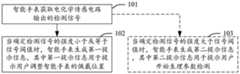
第四方面,提供一种贴片的在位检测方法,应用于第一方面的检测系统,包括:根据电化学传感器输出的检测信号,确定贴片的连接状态;当确定检测信号的强度小于或等于信号阈值时,生成第一提示信息,其中第一提示信息用于提示用户调整电子设备的佩戴位置。由于电化学传感电路输出的检测信号可以反应电子设备上的第一外接接口与贴片的第一电极接口的连接状态,例如如果检测信号的强度为零,则表明电子设备上的第一外接接口与贴片的第一电极接口完全断开,或者检测信号输出大于0但小于信号阈值,则说明电子设备上的第一外接接口与贴片的第一电极接口接触不良,存在高阻抗接触问题。此时需要通过调整电子设备佩戴的姿态以使电子设备上的第一外接接口与贴片的第一电极接口重新电连接。A fourth aspect provides an in-situ detection method for a patch, which is applied to the detection system of the first aspect, comprising: determining a connection state of the patch according to a detection signal output by an electrochemical sensor; when it is determined that the strength of the detection signal is less than or When it is equal to the signal threshold, first prompt information is generated, where the first prompt information is used to prompt the user to adjust the wearing position of the electronic device. Because the detection signal output by the electrochemical sensing circuit can reflect the connection state between the first external interface on the electronic device and the first electrode interface of the patch, for example, if the strength of the detection signal is zero, it indicates that the first external interface on the electronic device is connected If the interface is completely disconnected from the first electrode interface of the patch, or the detection signal output is greater than 0 but less than the signal threshold, it means that the first external interface on the electronic device is in poor contact with the first electrode interface of the patch, and there is a high-impedance contact problem . At this time, it is necessary to reconnect the first external interface on the electronic device with the first electrode interface of the patch by adjusting the wearing posture of the electronic device.
在一种可能是实现方式中,还包括:当确定检测信号的强度大于信号阈值时,生成第二提示信息,其中第二提示信息用于提示用户开始生理参数检测。In a possible implementation manner, the method further includes: when it is determined that the strength of the detection signal is greater than the signal threshold, generating second prompt information, where the second prompt information is used to prompt the user to start the detection of the physiological parameter.
在一种可能是实现方式中,第一提示信息包括:振动、声音、或显示信息。In a possible implementation manner, the first prompt information includes: vibration, sound, or display information.
第五方面,一种电子设备,该电子设备包括存储器和一个或多个处理器;该存储器和该处理器耦合;该存储器用于存储计算机程序代码,该计算机程序代码包括计算机指令;当该处理器执行该计算机指令时,使得该电子设备执行如第四方面中任一项的方法。In a fifth aspect, an electronic device includes a memory and one or more processors; the memory is coupled to the processor; the memory is used to store computer program code, the computer program code comprising computer instructions; when the processing When the computer executes the computer instructions, the electronic device is caused to perform the method of any one of the fourth aspects.
第六方面,提供一种计算机可读存储介质,包括计算机指令,当该计算机指令在电子设备上运行时,使得该电子设备执行第三方面中任一项的方法。In a sixth aspect, a computer-readable storage medium is provided, comprising computer instructions that, when executed on an electronic device, cause the electronic device to perform the method of any one of the third aspects.
其中,第二方面至第六方面所能实现的技术效果与第一方面类似,不在赘述。The technical effects that can be achieved by the second aspect to the sixth aspect are similar to those of the first aspect, and will not be repeated here.
附图说明Description of drawings
图1为现有技术提供的一种血糖检测产品的结构示意图;Fig. 1 is the structural representation of a kind of blood glucose detection product provided in the prior art;
图2为本申请的实施例提供的一种检测系统的场景示意图;FIG. 2 is a schematic diagram of a scene of a detection system provided by an embodiment of the present application;
图3为本申请的另一实施例提供的一种检测系统的场景示意图;3 is a schematic diagram of a scene of a detection system provided by another embodiment of the present application;
图4为本申请的实施例提供的一种电子设备的结构示意图;FIG. 4 is a schematic structural diagram of an electronic device according to an embodiment of the present application;
图5为本申请的实施例提供的一种贴片的结构示意图;5 is a schematic structural diagram of a patch provided by an embodiment of the present application;
图6为本申请的另一实施例提供的一种电子设备的结构示意图;6 is a schematic structural diagram of an electronic device according to another embodiment of the present application;
图7为本申请的实施例提供的一种电化学传感电路的结构示意图;7 is a schematic structural diagram of an electrochemical sensing circuit provided by an embodiment of the present application;
图8为本申请的另一实施例提供的一种贴片的结构示意图;FIG. 8 is a schematic structural diagram of a patch provided by another embodiment of the present application;
图9为本申请的又一实施例提供的一种贴片的结构示意图;FIG. 9 is a schematic structural diagram of a patch provided by another embodiment of the present application;
图10为本申请的再一实施例提供的一种贴片的结构示意图;10 is a schematic structural diagram of a patch provided by yet another embodiment of the present application;
图11为本申请的另一实施例提供的一种贴片的结构示意图;11 is a schematic structural diagram of a patch provided by another embodiment of the present application;
图12为本申请的实施例提供的一种微针的结构示意图;12 is a schematic structural diagram of a microneedle provided in an embodiment of the present application;
图13为本申请的另一实施例提供的一种微针的结构示意图;13 is a schematic structural diagram of a microneedle provided by another embodiment of the present application;
图14为本申请的又一实施例提供的一种微针的结构示意图;14 is a schematic structural diagram of a microneedle provided by another embodiment of the present application;
图15为本申请的再一实施例提供的一种微针的结构示意图;FIG. 15 is a schematic structural diagram of a microneedle provided by yet another embodiment of the present application;
图16为本申请的另一实施例提供的一种微针的结构示意图;16 is a schematic structural diagram of a microneedle provided by another embodiment of the present application;
图17为本申请的又一实施例提供的一种微针的结构示意图;17 is a schematic structural diagram of a microneedle provided by another embodiment of the present application;
图18为本申请的又一实施例提供的一种贴片的结构示意图;18 is a schematic structural diagram of a patch provided by another embodiment of the present application;
图19为本申请的再一实施例提供的一种贴片的结构示意图;FIG. 19 is a schematic structural diagram of a patch provided by still another embodiment of the present application;
图20为本申请的另一实施例提供的一种贴片的结构示意图;20 is a schematic structural diagram of a patch provided by another embodiment of the present application;
图21为本申请的又一实施例提供的一种贴片的结构示意图;21 is a schematic structural diagram of a patch provided by another embodiment of the present application;
图22为本申请的再一实施例提供的一种贴片的结构示意图;FIG. 22 is a schematic structural diagram of a patch provided by yet another embodiment of the present application;
图23为本申请的另一实施例提供的一种贴片的结构示意图;23 is a schematic structural diagram of a patch provided by another embodiment of the present application;
图24为本申请的又一实施例提供的一种贴片的结构示意图;FIG. 24 is a schematic structural diagram of a patch provided by another embodiment of the present application;
图25为本申请的再一实施例提供的一种微针的结构示意图;FIG. 25 is a schematic structural diagram of a microneedle provided by yet another embodiment of the application;
图26为本申请的又一实施例提供的一种电子设备的结构示意图;FIG. 26 is a schematic structural diagram of an electronic device according to another embodiment of the present application;
图27为本申请的再一实施例提供的一种电子设备的结构示意图;FIG. 27 is a schematic structural diagram of an electronic device according to still another embodiment of the present application;
图28为本申请的再一实施例提供的一种贴片的结构示意图;FIG. 28 is a schematic structural diagram of a patch provided by yet another embodiment of the present application;
图29为本申请的另一实施例提供的一种贴片的结构示意图;FIG. 29 is a schematic structural diagram of a patch provided by another embodiment of the application;
图30为本申请的又一实施例提供的一种贴片的结构示意图;FIG. 30 is a schematic structural diagram of a patch provided by another embodiment of the present application;
图31为本申请的再一实施例提供的一种贴片的结构示意图;FIG. 31 is a schematic structural diagram of a patch provided by yet another embodiment of the present application;
图32为本申请的另一实施例提供的一种电子设备的结构示意图;32 is a schematic structural diagram of an electronic device according to another embodiment of the present application;
图33为本申请的另一实施例提供的一种贴片的结构示意图;33 is a schematic structural diagram of a patch provided by another embodiment of the present application;
图34为本申请的又一实施例提供的一种贴片的结构示意图;FIG. 34 is a schematic structural diagram of a patch provided by another embodiment of the present application;
图35为本申请的实施例提供的一种工作电极的涂层的结构示意图;35 is a schematic structural diagram of a coating of a working electrode provided by an embodiment of the application;
图36为本申请的实施例提供的一种工作电极的涂层的工作原理示意图;36 is a schematic diagram of the working principle of a coating of a working electrode provided by an embodiment of the application;
图37为本申请的另一实施例提供的一种工作电极的涂层的结构示意图;37 is a schematic structural diagram of a coating of a working electrode provided by another embodiment of the application;
图38为本申请的另一实施例提供的一种工作电极的涂层的工作原理示意图;38 is a schematic diagram of the working principle of a coating of a working electrode provided by another embodiment of the application;
图39为本申请的实施例提供的一种贴片的在位检测方法的流程示意图;39 is a schematic flowchart of a method for in-situ detection of a patch provided by an embodiment of the present application;
图40为本申请的实施例提供的一种智能手表的显示界面示意图一;40 is a schematic diagram 1 of a display interface of a smart watch provided by an embodiment of the application;
图41为本申请的实施例提供的一种智能手表的显示界面示意图二;41 is a second schematic diagram of a display interface of a smart watch provided by an embodiment of the application;
图42为本申请的实施例提供的一种智能手表的显示界面示意图三;FIG. 42 is a schematic diagram 3 of a display interface of a smart watch provided by an embodiment of the application;
图43为本申请的实施例提供的一种智能手表的显示界面示意图四;FIG. 43 is a fourth schematic diagram of a display interface of a smart watch provided by an embodiment of the application;
图44为本申请的实施例提供的一种智能手表的显示界面示意图五;44 is a schematic diagram five of a display interface of a smart watch provided by an embodiment of the application;
图45为本申请的实施例提供的一种智能手表的显示界面示意图六;FIG. 45 is a sixth schematic diagram of a display interface of a smart watch provided by an embodiment of the application;
图46为本申请的又一实施例提供的一种电子设备的结构示意图;46 is a schematic structural diagram of an electronic device according to another embodiment of the present application;
图47为本申请的实施例提供的一种芯片系统的结构示意图。FIG. 47 is a schematic structural diagram of a chip system according to an embodiment of the present application.
具体实施方式Detailed ways
下面将结合本申请实施例中的附图,对本申请实施例中的技术方案进行描述,显然,所描述的实施例仅仅是本申请一部分实施例,而不是全部的实施例。The technical solutions in the embodiments of the present application will be described below with reference to the drawings in the embodiments of the present application. Obviously, the described embodiments are only a part of the embodiments of the present application, rather than all the embodiments.
除非另有定义,否则本文所用的所有科技术语都具有与本领域普通技术人员公知的含义相同的含义。在本申请中,“至少一个”是指一个或者多个,“多个”是指两个或两个以上。“和/或”,描述关联对象的关联关系,表示可以存在三种关系,例如,A和/或B,可以表示:单独存在A,同时存在A和B,单独存在B的情况,其中A,B可以是单数或者复数。字符“/”一般表示前后关联对象是一种“或”的关系。“以下至少一项(个)”或其类似表达,是指的这些项中的任意组合,包括单项(个)或复数项(个)的任意组合。例如,a,b或c中的至少一项(个),可以表示:a,b,c,a和b,a和c,b和c或a、b和c,其中a、b和c可以是单个,也可以是多个。另外,在本申请的实施例中,“第一”、“第二”等字样并不对数量和次序进行限定。Unless otherwise defined, all technical and scientific terms used herein have the same meaning as commonly understood by one of ordinary skill in the art. In this application, "at least one" means one or more, and "plurality" means two or more. "And/or", which describes the association relationship of the associated objects, indicates that there can be three kinds of relationships, for example, A and/or B, which can indicate: the existence of A alone, the existence of A and B at the same time, and the existence of B alone, where A, B can be singular or plural. The character "/" generally indicates that the associated objects are an "or" relationship. "At least one item(s) below" or similar expressions thereof refer to any combination of these items, including any combination of single item(s) or plural items(s). For example, at least one (a) of a, b or c may represent: a, b, c, a and b, a and c, b and c or a, b and c, where a, b and c can be It can be single or multiple. In addition, in the embodiments of the present application, words such as "first" and "second" do not limit the quantity and order.
此外,本申请中,“上”、“下”等方位术语是相对于附图中的部件示意置放的方位来定义的,应当理解到,这些方向性术语是相对的概念,它们用于相对于的描述和澄清,其可以根据附图中部件所放置的方位的变化而相应地发生变化。In addition, in this application, orientation terms such as "upper" and "lower" are defined relative to the orientation in which the components in the drawings are schematically placed. It should be understood that these directional terms are relative concepts, and they are used for relative In the description and clarification of the drawings, it may change correspondingly according to the change of the orientation in which the components are placed in the drawings.
需要说明的是,本申请中,“示例性的”或者“例如”等词用于表示作例子、例证或说明。本申请中被描述为“示例性的”或者“例如”的任何实施例或设计方案不应被解释为比其他实施例或设计方案更优选或更具优势。确切而言,使用“示例性的”或者“例如”等词旨在以具体方式呈现相关概念。It should be noted that, in this application, words such as "exemplary" or "for example" are used to represent examples, illustrations or illustrations. Any embodiment or design described in this application as "exemplary" or "such as" should not be construed as preferred or advantageous over other embodiments or designs. Rather, the use of words such as "exemplary" or "such as" is intended to present the related concepts in a specific manner.
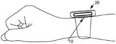
一种血糖检测产品包括贴片和读写器。其中,贴片上包含一根针状的葡萄糖传感电极,以及恒电位仪电路模块、数据处理模块、传输模块。其中,贴片可以佩戴于人体,如图1所示,贴片10直接贴敷在患者腹部(当然也可以贴敷在人体的其他部分,例如上臂),这样,葡萄糖传感电极可以刺入患者的皮肤(例如,葡萄糖传感电极刺穿皮肤的表皮进入到真皮,与血液接触,这样血液中的葡萄糖在葡萄糖传感电极上产生电化学反应)。恒电位仪电路模块能够检测葡萄糖传感电极上电化学反应产生的电信号,并将电信号经数据处理模块处理转换成数字信号,最后,传输模块将数字信号转换为射频信号发送至读写器20(可以是智能穿戴设备,例如手表,或者专用血糖仪),这样读写器20可以获取贴片的血糖数据,并显示。其中,这种贴片10的葡萄糖传感电极需要置入人体皮肤,为避免葡萄糖传感电极长期置入皮肤造成感染(或葡萄糖传感电极正常使用失效),因此贴片10贴敷在患者腹部后通常有一定的使用期限,例如,最多3到5日需要更换。因此作为一种耗材,贴片10上同时集成葡萄糖传感电极,以及恒电位仪电路模块、数据处理模块、传输模块;造成贴片的结构较为复杂,提高了使用成本。A blood glucose testing product includes a patch and a reader. Among them, the patch includes a needle-shaped glucose sensing electrode, as well as a potentiostat circuit module, a data processing module, and a transmission module. Among them, the patch can be worn on the human body. As shown in FIG. 1, the
为解决上述问题,结合图2、图3、图4以及图5所示的应用场景,对本申请的实施例提供的方案的原理简述如下:其中,本申请的实施例提供一种电子设备、贴片及检测系统,主要用于包括血糖、血脂、血氧等任一生理参数的检测。在本申请的实施例中,不需要在贴片10上设置诸如电化学传感电路、数据处理模块、传输模块等电路模块,在贴片10上仅设置用于置入人体皮肤的微针13、以及微针13上的电极11(图5中示出三个电极11-1、11-2以及11-3);将而电化学传感电路22(如图4所示)、数据处理模块等电路模块设置于电子设备20上(例如可以是智能手表等穿戴设备),其中在电子设备20的背面(如图3所示,正常佩戴时朝向人体的一面)设置有至少两个与电化学传感电路22耦合的外接接口21(图4中示出三个外接接口21-1、21-2、21-3)。并且,在贴片10上设置有与电极11耦合的电极接口12(图5中示出三个电极接口12-1、12-2、12-3)。这样,将贴片10贴敷于人体时(如图5所示),微针15刺入人体的真皮,这样使得电极11可以与真皮的血液相接触,当电子设备20佩戴于人体(例如腕部,参照图3所示)时,电子设备20上的外接接口21与贴片10的电极接口12形成电连接(如图2中虚线示出的电连接关系)。贴片10和电子设备20之间可以传输电信号;这样,在血液中的成分(例如葡萄糖、氧气、血脂等)在电极11上产生电化学反应,形成电信号,具体的对于测血糖,可以是血液中的葡萄糖在电极11中的工作电极上涂覆的涂层中产生电化学反应,形成电信号。从而使得电化学传感电路22能够检测到电化学反应形成的电信号,电子设备20进而将电信号转换为检测信号实现生理参数的检测。这样,由于不在贴片10上设置诸如电化学传感电路、数据处理模块、传输模块等电路模块,简化了贴片10的结构,从而降低了使用成本。并且在一些方案中,可以将外接接口21以及电极接口12中的至少一者设置为具有磁性的接口,例如可采用磁性材料,以将外接接口21以及电极接口12吸合,确保两者之间电连接的可靠性。并且当有外力扰动电子设备20时,外接接口21与电极接口12可以脱离,避免电子设备20的扰动牵连贴片10对人体皮肤划伤。当然,也可以在电子设备20以及贴片10单独设置磁吸接口实现两者的吸合。以上简述了本申请的实施例提供的产品的原理及主要技术方案,以下将结合具体示例详细描述。In order to solve the above problems, in conjunction with the application scenarios shown in FIG. 2 , FIG. 3 , FIG. 4 and FIG. 5 , the principle of the solution provided by the embodiment of the present application is briefly described as follows: wherein, the embodiment of the present application provides an electronic device, The patch and detection system are mainly used for the detection of any physiological parameters including blood sugar, blood lipids, blood oxygen, etc. In the embodiment of the present application, it is not necessary to provide circuit modules such as electrochemical sensing circuits, data processing modules, transmission modules, etc. on the
示例性的,本申请实施例中的电子设备可以是智能手表、智能腕环、智能腰带等穿戴设备,本申请实施例对该电子设备的具体形态不作特殊限制。Exemplarily, the electronic device in the embodiment of the present application may be a wearable device such as a smart watch, a smart wristband, and a smart belt, and the specific form of the electronic device is not particularly limited in the embodiment of the present application.
下面将结合附图对本申请实施例的实施方式进行详细描述。请参考图6所示,为本申请实施例提供的一种电子设备20的结构示意图。如图2所示,电子设备20可以包括:处理器210,外部存储器接口220,内部存储器221,通用串行总线(universal serial bus,USB)接口230,充电管理模块240,电源管理模块241,电池242,天线1,天线2,移动通信模块250,无线通信模块260,音频模块270,扬声器270A,受话器270B,麦克风270C,耳机接口270D,传感器模块280,按键290,振动电机291,外接接口21,摄像头292,显示屏293,用户标识模块(subscriber identification module,SIM)卡接口294、电化学传感电路22以及指示器295等。The implementation of the embodiments of the present application will be described in detail below with reference to the accompanying drawings. Please refer to FIG. 6 , which is a schematic structural diagram of an
可以理解的是,本实施例示意的结构并不构成对电子设备20的具体限定。在另一些实施例中,电子设备20可以包括比图示更多或更少的部件,或者组合某些部件,或者拆分某些部件,或者不同的部件布置。图示的部件可以以硬件,软件或软件和硬件的组合实现。可以理解的是,本实施例示意的各模块间的接口连接关系,只是示意性说明,并不构成对电子设备20的结构限定。在另一些实施例中,电子设备20也可以采用上述实施例中不同的接口连接方式,或多种接口连接方式的组合。It can be understood that the structure illustrated in this embodiment does not constitute a specific limitation on the
处理器210可以包括一个或多个处理单元,例如:处理器210可以包括应用处理器(application processor,AP),调制解调处理器,图形处理器(graphics processingunit,GPU),图像信号处理器(image signal processor,ISP),控制器,存储器,视频编解码器,数字信号处理器(digital signal processor,DSP),基带处理器,和/或神经网络处理器(neural-network processing unit,NPU)等。其中,不同的处理单元可以是独立的器件,也可以集成在一个或多个处理器中。处理器可以是电子设备20的神经中枢和指挥中心。处理器可以根据指令操作码和时序信号,产生操作控制信号,完成取指令和执行指令的控制。The
处理器210中还可以设置存储器,用于存储指令和数据。在一些实施例中,处理器210中的存储器为高速缓冲存储器。该存储器可以保存处理器210刚用过或循环使用的指令或数据。如果处理器210需要再次使用该指令或数据,可从存储器中直接调用。避免了重复存取,减少了处理器210的等待时间,因而提高了系统的效率。A memory may also be provided in the
在一些实施例中,处理器210可以包括一个或多个接口。接口可以包括集成电路(inter-integrated circuit,I2C)接口,集成电路内置音频(inter-integrated circuitsound,I2S)接口,脉冲编码调制(pulse code modulation,PCM)接口,通用异步收发传输器(universal asynchronous receiver/transmitter,UART)接口,移动产业处理器接口(mobile industry processor interface,MIPI),通用输入输出(general-purposeinput/output,GPIO)接口,用户标识模块(subscriber identity module,SIM)接口,和/或通用串行总线(universal serial bus,USB)接口等。In some embodiments, the
外部存储器接口220可以用于连接外部存储卡,例如Micro SD卡,实现扩展电子设备20的存储能力。外部存储卡通过外部存储器接口与处理器210通信,实现数据存储功能。例如将音乐,视频等文件保存在外部存储卡中。The external memory interface 220 can be used to connect an external memory card, such as a Micro SD card, to expand the storage capacity of the
内部存储器221可以用于存储计算机可执行程序代码,该可执行程序代码包括指令。处理器210通过运行存储在内部存储器221的指令,从而执行电子设备20的各种功能应用以及数据处理。例如,在本申请实施例中,处理器210可以通过执行存储在内部存储器221中的指令,内部存储器221可以包括存储程序区和存储数据区。Internal memory 221 may be used to store computer executable program code, which includes instructions. The
其中,存储程序区可存储操作系统,至少一个功能所需的应用程序(比如声音播放功能,图像播放功能等)等。存储数据区可存储电子设备20使用过程中所创建的数据(比如音频数据,电话本等)等。此外,内部存储器221可以包括高速随机存取存储器,还可以包括非易失性存储器,例如至少一个磁盘存储器件,闪存器件,通用闪存存储器(universalflash storage,UFS)等。The storage program area can store an operating system, an application program required for at least one function (such as a sound playback function, an image playback function, etc.), and the like. The storage data area can store data (such as audio data, phone book, etc.) created during the use of the
充电管理模块240用于从充电器接收充电输入。其中,充电器可以是无线充电器,也可以是有线充电器。在一些有线充电的实施例中,充电管理模块240可以通过USB接口230接收有线充电器的充电输入。在一些无线充电的实施例中,充电管理模块240可以通过电子设备20的无线充电线圈接收无线充电输入。充电管理模块240为电池241充电的同时,还可以通过电源管理模块241为电子设备20供电。The
电源管理模块241用于连接电池241,充电管理模块240与处理器210。电源管理模块241接收电池241和/或充电管理模块240的输入,为处理器210,内部存储器221,外部存储器,显示屏293,摄像头292,和无线通信模块260等供电。电源管理模块241还可以用于监测电池容量,电池循环次数,电池健康状态(漏电,阻抗)等参数。在其他一些实施例中,电源管理模块241也可以设置于处理器210中。在另一些实施例中,电源管理模块241和充电管理模块240也可以设置于同一个器件中。The
电子设备20的无线通信功能可以通过天线1,天线2,移动通信模块250,无线通信模块260,调制解调处理器以及基带处理器等实现。The wireless communication function of the
天线1和天线2用于发射和接收电磁波信号。电子设备20中的每个天线可用于覆盖单个或多个通信频带。不同的天线还可以复用,以提高天线的利用率。例如:可以将天线1复用为无线局域网的分集天线。在另外一些实施例中,天线可以和调谐开关结合使用。
移动通信模块250可以提供应用在电子设备20上的包括2G/3G/4G/5G等无线通信的解决方案。移动通信模块250可以包括至少一个滤波器,开关,功率放大器,低噪声放大器(low noise amplifier,LNA)等。The
无线通信模块260可以提供应用在电子设备20上的无线局域网(wireless localarea networks,WLAN),蓝牙(bluetooth,BT),全球导航卫星系统(globalnavigationsatellite system,GNSS),调频(frequency modulation,FM),近距离无线通信技术(nearfield communication,NFC),红外技术(infrared,IR)等无线通信的解决方案。例如,上述WLAN可以为(wireless fidelity,Wi-Fi)网络。The wireless communication module 260 may provide wireless local area networks (WLAN), bluetooth (BT), global navigation satellite system (GNSS), frequency modulation (FM), Solutions for wireless communication such as distance wireless communication technology (nearfield communication, NFC), infrared technology (infrared, IR). For example, the above-mentioned WLAN may be a (wireless fidelity, Wi-Fi) network.
无线通信模块260可以是集成至少一个通信处理模块的一个或多个器件。无线通信模块260经由天线2接收电磁波,将电磁波信号调频以及滤波处理,将处理后的信号发送到处理器210。无线通信模块260还可以从处理器210接收待发送的信号,对其进行调频,放大,经天线2转为电磁波辐射出去。The wireless communication module 260 may be one or more devices integrating at least one communication processing module. The wireless communication module 260 receives electromagnetic waves via the antenna 2 , modulates and filters the electromagnetic wave signals, and sends the processed signals to the
在一些实施例中,电子设备20的天线2和移动通信模块250耦合,天线2和无线通信模块260耦合,使得电子设备20可以通过无线通信技术与网络以及其他设备通信。In some embodiments, the antenna 2 of the
电子设备20通过GPU,显示屏293,以及应用处理器等实现显示功能。GPU为图像处理的微处理器,连接显示屏293和应用处理器。GPU用于执行数学和几何计算,用于图形渲染。处理器210可包括一个或多个GPU,其执行程序指令以生成或改变显示信息。显示屏293可以是触摸屏,该显示屏293用于显示图像,视频等。该显示屏292包括显示面板。The
电子设备20可以通过ISP,摄像头292,视频编解码器,GPU,显示屏293以及应用处理器等实现拍摄功能。ISP用于处理摄像头292反馈的数据。在一些实施例中,ISP可以设置在摄像头292中。摄像头292用于捕获静态图像或视频。在一些实施例中,电子设备20可以包括1个或M个摄像头292,M为大于1的正整数。The
电子设备20可以通过音频模块270,扬声器270A,受话器270B,麦克风270C,耳机接口270D,以及应用处理器等实现音频功能。例如音乐播放,录音等。The
音频模块270用于将数字音频信息转换成模拟音频信号输出,也用于将模拟音频输入转换为数字音频信号。耳机接口270D用于连接有线耳机。耳机接口270D可以是USB接口230,也可以是3.5mm的开放移动电子设备平台(open mobile terminal platform,OMTP)标准接口,美国蜂窝电信工业协会(cellular telecommunications industry associationof the USA,CTIA)标准接口。The
其中,上述传感器模块280可以包括陀螺仪传感器,气压传感器,磁传感器,加速度传感器,距离传感器,接近光传感器,指纹传感器,温度传感器,触摸传感器,环境光传感器和骨传导传感器等传感器。The aforementioned sensor module 280 may include sensors such as a gyro sensor, an air pressure sensor, a magnetic sensor, an acceleration sensor, a distance sensor, a proximity light sensor, a fingerprint sensor, a temperature sensor, a touch sensor, an ambient light sensor, and a bone conduction sensor.
按键290包括开机键,音量键等。按键290可以是机械按键。也可以是触摸式按键。电子设备20可以接收按键输入,产生与电子设备20的用户设置以及功能控制有关的键信号输入。The keys 290 include a power-on key, a volume key, and the like. Keys 290 may be mechanical keys. It can also be a touch key. The
振动电机291,也可以称为马达,可以用于振动提示。振动电机291可以用于来电振动提示。例如,作用于不同应用(例如拍照,音频播放等)的触摸操作,可以对应发出不同的振动反馈效果。作用于显示屏293不同区域的触摸操作,振动电机291也可对应不同的振动反馈效果。不同的应用场景(例如:时间提醒,接收信息,闹钟,游戏等)也可以对应不同的振动反馈效果。触摸振动反馈效果还可以支持自定义。Vibration motor 291, which may also be referred to as a motor, may be used for vibrating cues. The vibration motor 291 can be used to vibrate for incoming calls. For example, a touch operation acting on different applications (such as taking pictures, playing audio, etc.) can correspondingly emit different vibration feedback effects. For touch operations on different areas of the display screen 293, the vibration motor 291 can also correspond to different vibration feedback effects. Different application scenarios (for example: time reminder, receiving information, alarm clock, games, etc.) can also correspond to different vibration feedback effects. The touch vibration feedback effect can also support customization.
本申请实施例中的振动电机291、显示屏293、扬声器270A可以用于向用户展示提示用户调整电子设备20的佩戴位置的第一提示信息,或者向用户提示开始生理参数检测的第二提示信息。The vibration motor 291 , the display screen 293 , and the speaker 270A in the embodiment of the present application may be used to display to the user first prompt information for prompting the user to adjust the wearing position of the
外接接口21用于连接外部设备。例如本申请的实施例提供的贴片,其中外接接口的形式可以为电极盘、电极块或导电块凸起等等,电子设备20可以支持2个或N个外接接口,N为大于2的正整数。The
SIM卡接口294用于连接SIM卡。SIM卡可以通过插入SIM卡接口294,或从SIM卡接口294拔出,实现和电子设备20的接触和分离。电子设备20可以支持1个或N个SIM卡接口,N为大于1的正整数。SIM卡接口294可以支持Nano SIM卡,Micro SIM卡,SIM卡等。其中,可以理解的是,当电子设备20为不具备2G/3G/4G/5G等移动通信功能的穿戴设备时,穿戴设备上也可以不设置SIM卡接口294以及移动通信模块250,即SIM卡接口294以及移动通信模块250可以为可选的部件。The SIM card interface 294 is used to connect a SIM card. The SIM card can be contacted and separated from the
其中,上述电化学传感电路22可以包括基于安培法、计时电流法、循环伏安法、差分脉冲伏安法、交流阻抗法等在内的多种电化学方法的电信号检测电路。结合图7所示,提供了一种电化学传感电路22的结构示意图,包括运算放大器OP1、运算放大器OP2,其中,运算放大器OP1的反向端(-)连接贴片10的参考电极(reference electrode,RE),运算放大器OP1的输出端连接贴片10的对电极(counter electrode,CE),运算放大器OP2的反向端(-)通过电阻R连接运算放大器OP2的输出端,运算放大器OP2的反向端(-)还连接贴片10的工作电极(work electrode,WE),运算放大器OP2的正向端(+)连接接地端GND。其中,运算放大器OP1的作用是反馈,通过运算放大器OP1的“虚短”使得RE的电压等于运算放大器OP1的正向端(+)输入的电压ei,而且RE连接的OP1的反向端(-)由于“虚断”无电流流过,使得电流只从WE和CE两个电极之间流过;OP2的作用是实现互阻抗放大,将流过WE和CE的电流,通过R转换成电压eo。当然,贴片10是以三电极为例进行说明的,当贴片10包括WE和CE两电极时,可以将RE直接与CE短接。当然,以上电化学传感电路22是以用于测血糖的电化学传感电路22为例,当用于其他的生理参数检测时,电化学传感电路22也可以有其他结构。The
指示器295可以是指示灯,可以用于指示充电状态,电量变化,也可以用于指示消息,未接来电,通知等。The indicator 295 can be an indicator light, which can be used to indicate the charging status, the change of power, and can also be used to indicate messages, missed calls, notifications, and the like.
以下实施例中的方案具有上述硬件结构的电子设备可以为穿戴设备。以智能手表为例,具体的,参照图4所示,智能手表20包括电化学传感电路22、以及设置在智能手表20的背面(如图2所示)的外接接口21,其中,外接接口21与电化学传感电路22耦合。其中,图4中的电化学传感电路22可以为图6中的电化学传感电路22,图4中的外接接口21可以为图6中的外接接口21。The electronic device having the above-mentioned hardware structure in the solutions in the following embodiments may be a wearable device. Taking a smart watch as an example, specifically, as shown in FIG. 4 , the
其中,智能手表20的背面朝向人体佩戴时,外接接口21(如图4示出三个外接接口21-1、21-2、21-3)与贴片10上的电极接口12(如图8示出三个电极接口12-1、12-2、12-3)连接后向电化学传感电路22传输贴片10产生的电信号,电化学传感电路22用于将电信号转换为检测信号。例如,电化学传感电路22具体可以将该检测信号传输至智能手表的数字信号处理器,由数字信号处理器将检测信号转换为显示信号输出至显示屏,从而向用户显示检测的血糖值。具体的,结合上述的图7提供的电化学传感电路22,以血糖检测为例,贴片10产生的电信号具体可以是WE和CE两个电极之间流过的电流;检测信号具体可以是将流过WE和CE的电流,转换成的电压eo;数字信号处理器可以将电压eo进行模数转换,转换成指示血液中血糖(葡萄糖)含量的血糖值(例如:6.0mg/dL(毫克/分升))的显示信号,通过显示信号驱动在显示屏293上显示该血糖值。Wherein, when the back of the
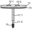
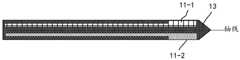
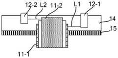
本申请的实施例还提供一种配合上述的智能手表20使用的贴片,参照图8所示,贴片10包括基底14,设置在基底14的第一表面的电极接口12(以能够实现血糖检测的贴片10为例,包括三电极,则需要设置三个电极接口12-1、12-2、12-3),设置在基底14的第二表面的胶黏层15,第二表面背向于第一表面;贴片10还包括设置在基底14的第二表面的微针13;其中微针13上设置有电极11(其中图8以一个微针13为例,其上设置有三个电极11-1、11-2、11-3),微针13上设置的电极至少包括工作电极WE以及参比电极RE,其中工作电极WE上涂覆有用于生理参数检测的多个涂层。电极11(11-1、11-2、11-3)与电极接口12(12-1、12-2、12-3)一对一耦合。其中,图8中以三电极为例进行说明,则除了包括工作电极WE以及参比电极RE外,还包括对电极CE,其中工作电极WE、参比电极RE以及电极CE可以为电极11(11-1、11-2、11-3)中的任一一个。例如,电极11-1为参比电极RE、电极11-2为对电极、电极11-3为工作电极WE。基底14的材料包括但不限于聚酰亚胺(polyimide,PI)、聚对苯二甲酸乙二醇酯(polyethylene terephthalate,PET)、聚二甲基硅氧烷(polydimethylsiloxane,PDMS)、聚氨酯(polyurethane,PU)等;胶黏层15主要用于将贴片10粘贴于皮肤,避免脱落,胶黏层15可以采用亲肤材料,包括但不限于硅凝胶。The embodiment of the present application also provides a patch for use with the above-mentioned
以两电极为例进行说明,参照图9所示,工作电极WE、参比电极RE可以为电极11(11-1、11-2)中的任一一个。例如,电极11-1为参比电极RE、电极11-2为工作电极WE。其中,为了说明电极11与电极接口12的耦合方式,参照图10和图11所示,电极11-1通过导线L1与电极接口12-1电连接,电极11-2通过导线L2与电极接口12-2电连接,其中导线L1(L2)可以采用绑定(bonding)方式连接两端的导电结构。Taking two electrodes as an example for description, referring to FIG. 9 , the working electrode WE and the reference electrode RE may be any one of the electrodes 11 ( 11 - 1 , 11 - 2 ). For example, the electrode 11-1 is the reference electrode RE, and the electrode 11-2 is the working electrode WE. 10 and 11, the electrode 11-1 is electrically connected to the electrode interface 12-1 through the wire L1, and the electrode 11-2 is electrically connected to the
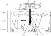
这样,将贴片10贴敷于人体时(如图5所示),微针13刺入人体的真皮,这样使得电极11可以与真皮的血液相接触;当智能手表20佩戴于人体(例如腕部)时,智能手表20上的外接接口21与贴片的电极接口12形成电连接(如图2中虚线示出的电连接关系,其中以三电极的贴片为例,参照图4所示,例如外接接口21-1与电极接口12-1电连接,外接接口21-2与电极接口12-2电连接,外接接口21-3与电极接口12-3电连接);贴片10和电子设备20之间可以传输电信号;这样,在血液中的成分(例如葡萄糖、氧气、血脂等)在电极上产生电化学反应,形成电信号。例如,对于血糖检测,血液中的葡萄糖在电极接口12中的工作电极WE上涂覆的涂层上产生电化学反应,形成电信号。从而使得电化学传感电路22能够检测到电化学反应形成的电信号,进而将电信号转换为检测信号实现生理参数的检测。这样,由于不在贴片10上设置诸如电化学传感电路、数据处理模块、传输模块等电路模块,简化了贴片10的结构,从而降低了使用成本。In this way, when the
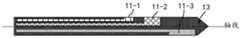
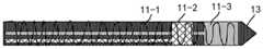
其中,上述的电极11的形状包括:柱状、面状或绕线状。其中,以三电极的贴片10为例,参照图12所示,电极11-1、电极11-2以及电极11-3可以为在微针13上依次排列的三个面状的导电结构。以两电极的贴片10为例,参照图13所示,电极11-1、电极11-2可以为在微针13上依次排列的两个面状的导电结构。为了提高电极11与皮肤的真皮的接触面积,如图14、图15所示,各个面状的电极可以分别设置在沿微针的轴线相对的两个方向上。以三电极的贴片10为例,参照图14所示,电极11-1、电极11-2沿微针的轴线设置在同一侧,电极11-3沿微针的轴线设置在另一侧。以两电极的贴片10为例,参照图15所示,电极11-1、电极11-2沿微针的轴线分别设置在两侧。为了提高电极与皮肤的真皮层的接触面积,还可以将电极设置为柱状或者绕线状,如图8所示,以三电极的贴片10为例,电极11-1、电极11-2以及电极11-3可以形成在微针13上依次排列的三个柱状的导电结构,其中如图8所示,各个电极的直径不同,例如电极11-1的直径大于电极11-2的直径,电极11-2的直径大于电极11-3的直径。如图9所示,以两电极的贴片10为例,电极11-1、电极11-2可以形成在微针13上依次排列的两个柱状的导电结构,其中如图9所示,各个电极的直径不同,例如电极11-1的直径大于电极11-2的直径。参照图16所示,以三电极的贴片10为例,电极11-1可以采用绕线状的导电结构缠绕在微针13上,对另外两个电极的形状不做限定,但是需要说明的是,绕线状的电极11-1需要与电极11-2以及电极11-3做绝缘处理。类似的如图17所示,以两电极的贴片10为例,电极11-1可以采用绕线状的导电结构缠绕在微针13上,对另外一个电极的形状不做限定,但是需要说明的是,绕线状的电极11-1需要与电极11-2做绝缘处理。Wherein, the shape of the above-mentioned
此外,电极的材料包括但不限于以下一种或多种材料:灯黑碳(lamp blackcarbon)、玻璃碳、石墨、银、氯化银、铂、钯、铂铱合金、钛、金以及铱。尤其,参比电极RE可以采用银或氯化银,由于银或氯化银电极在水溶液体系中具有很小的溶解度、极高的稳定性和可逆性,且即使在有氢存在的情况下电极表面也会得到很好的保护,因此用作参比电极时,可以尽量降低电极自噪声。In addition, the material of the electrode includes, but is not limited to, one or more of the following materials: lamp black carbon, glassy carbon, graphite, silver, silver chloride, platinum, palladium, platinum-iridium alloy, titanium, gold, and iridium. In particular, silver or silver chloride can be used as the reference electrode RE, because silver or silver chloride electrode has little solubility in aqueous system, high stability and reversibility, and even in the presence of hydrogen The surface is also well protected, so electrode self-noise can be minimized when used as a reference electrode.
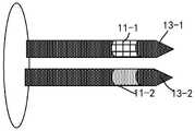
以上主要是以贴片10具有一个微针为例进行说明,此外贴片10也可以具有两个或多个微针,如图18所示,贴片10具有两个微针13-1和13-2。结合图19-图22所示,还提供了两电极以及三电极形式的贴片10的电极在两个微针上的设置方式。具体参照图19所示,以两电极的贴片10为例,可以将电极11-1设置在微针13-1上,可以将电极11-2设置在微针13-2上,其中图19中的电极形状以柱状为例,如上述,电极形状也可以为其他形状。参照图20-图22所示,以三电极的贴片10为例,可以将电极11-1、电极11-2设置在微针13-1上,可以将电极11-3设置在微针13-2上。或者可以将电极11-1、电极11-3设置在微针13-2上,可以将电极11-2设置在微针13-1上。等等,可以理解的是,将三个电极设置在两个微针上还有其他形式,此处不再列举。此外,图20和图21主要是以面状的电极为例,图22主要是以柱状的电极为例进行说明,如上述,电极形状也可以为其他形状。The above description is mainly based on the example that the
如图23所示,贴片10具有三个微针(13-1、13-2和13-3)。结合图34所示,以三电极的贴片10为例,可以将电极11-1设置在微针13-1上,可以将电极11-2设置在微针13-2上,可以将电极11-3设置在微针13-2上,其中图24中的电极形状以柱状为例,如上述,电极形状也可以为其他形状。As shown in Figure 23, the
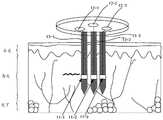
其中,贴片10贴敷至皮肤时,需要将微针刺破表皮植入皮下组织上部的真皮才能确保电极有效接触血液。植入方式可以采用主动按压的方式,例如用户手动将贴片10贴敷于手腕背部,微针刺入皮下;或者采用助针器辅助植入的方式。Wherein, when the
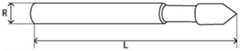
其中,为了保证植入快,痛感低,创面小,并且确保微针的长度足够置入皮下。如图25所示,微针的长度L为1-5mm,微针的直径R为7-400μm。此外,上述示例中,微针13的材料包括但不限于不锈钢、铂或高分子材料。结合微针的两种植入方式,采用主动按压方式时,由于使用者的动作快慢有别,通常微针采用刚性材料,例如不锈钢等。此外,为确保植入快,痛感低,创面小的要求,微针的针尖形状可以设计为松叶状。采用助针器辅助植入方式时,由于助针器可以具有较高的置入速度,因此针体可以采用柔性材料,例如高分子材料、铂等,由于助针器可以具有较高的置入速度对微针的针尖无需特殊设计。Among them, in order to ensure fast implantation, low pain, small wound, and to ensure that the length of the microneedle is sufficient to be placed under the skin. As shown in FIG. 25 , the length L of the microneedle is 1-5 mm, and the diameter R of the microneedle is 7-400 μm. In addition, in the above examples, the materials of the
此外,可以将外接接口21设置为具有磁性的接口或者采用磁性材料,将电极接口12设置为具有磁性的接口或者采用磁性材料。例如:外接接口21以及电极接口12可以采用钕铁硼、钐钴、铝镍钴以及铁铬钴等磁性材料,并且可以采用磁场对磁性材料磁化使磁性材料具有磁性。为了确保外接接口21与电极接口12之间电连接的可靠性,可以采用磁性将外接接口21以及电极接口12吸合。具体的,外接接口21以及电极接口12可以均具有磁性(例如相反的磁性),或者一者具有磁性,另一者为磁性材料。此外,当外接接口21与电极接口12均采用磁性材料时,可以在外接接口21与电极接口12相接触的表面采用电镀或金属沉积等工艺制作一层或多层镍、铜等高导电率的材料,以增加外接接口21与电极接口12的导电性。这样,由于外接接口21以及电极接口12采用弱磁方式吸合可以确保两者之间电连接的可靠性,当有外力扰动电子设备20时,外接接口21以及电极接口12可以脱离,避免电子设备20的扰动牵连贴片10对人体皮肤划伤。In addition, the
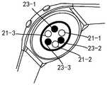
当然,也可以在智能手表20以及贴片10单独设置磁吸接口实现两者的吸合,具体的参照图26所示,可以在智能手表20的内部,外接接口21的内侧设置与外接接口21一一对应的第二磁吸接口23(例如,以三电极的贴片10场景为例,外接接口21-1的内侧设置第二磁吸接口23-1,外接接口21-2的内侧设置第二磁吸接口23-2,外接接口21-3的内侧设置第二磁吸接口23-3),其中第二磁吸接口23具有磁性,或者第二磁吸接口23为磁性材料。这样,电极接口12设置为具有磁性的接口或者采用磁性材料时,可以通过第二磁吸接口23将电子设备20以及贴片10吸合,以确保外接接口21与电极接口12电连接的可靠性。Of course, the
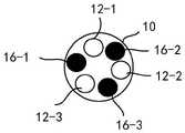
此外,参照图27、图28所示,也可以在贴片10的基底的第一表面设置第一磁吸接口16,第一磁吸接口16具有磁性,或者第一磁吸接口16为磁性材料。在智能手表20设置第二磁吸接口23,第二磁吸接口23具有磁性,或者第二磁吸接口23为磁性材料。其中第二磁吸接口23的一面漏出电子设备20。具体的,第一磁吸接口16以及第二磁吸接口23可以均具有磁性(例如相反的磁性),或者一者具有磁性,另一者为磁性材料。第一磁吸接口16与第二磁吸接口23的位置一一对应,并且通过第一磁吸接口16与第二磁吸接口23将智能手表20以及贴片10吸合后,外接接口21与电极接口12电连接。具体的以三电极的贴片10场景为例,第一磁吸接口16-1与第二磁吸接口23-1的位置对应并吸合,第一磁吸接口16-2与第二磁吸接口23-2的位置对应并吸合,第一磁吸接口16-3与第二磁吸接口23-3的位置对应并吸合。当然以上是智能手表20包含三个第二磁吸接口23以及贴片10包含三个第一磁吸接口16为例进行说明,其中,由于在一个面上通过固定两点可以确保该平面不能沿垂直该面的轴线转动,因此为了确保外接接口21与电极接口12电连接的可靠性,即避免智能手表沿垂直于智能手表显示平面的一条轴线转动,造成外接接口21与电极接口12脱离,则智能手表20上至少需要设置两个位置不同的第二磁吸接口23,并且贴片10上至少需要设置两个位置不同的第一磁吸接口16。In addition, as shown in FIG. 27 and FIG. 28 , the first magnetic interface 16 may also be provided on the first surface of the base of the
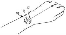
此外,为了确保智能手表20上的外接接口21与贴片10的电极接口12形成正确的连接方式,例如,以三电极的贴片为例,需要确保贴片贴敷至皮肤后,智能手表的外接接口21-1与贴片的电极接口12-1电连接,外接接口21-2与电极接口12-2电连接,外接接口21-3与电极接口12-3电连接。则基底14的第一表面上设置有贴敷标记17,贴敷标记17用于指示贴片的贴敷方向。如图29所示,在将贴片贴敷至皮肤时,贴敷标记17指示朝向无名指和中指之间的方向贴敷。In addition, in order to ensure a correct connection between the
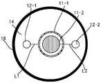
在另一个示例中,贴片的电极接口为同心设置的圆环状电极接口,对应的智能手表的外接接口为同心设置的圆环状外接接口。以两电极的贴片为例,参照图30、图31,电极接口12-1与电极接口12-2可以为同心设置的圆环状电极接口;电极接口12-1通过导线L1耦合电极11-1,电极接口12-2通过导线L2耦合电极11-2。如图32所示,外接接口21-1与外接接口21-1可以为同心设置的圆环状外接接口;智能手表20与贴片10贴合后,电极接口12-1与外接接口21-1电连接,电极接口12-2与外接接口21-2电连接。In another example, the electrode interface of the patch is a concentric annular electrode interface, and the corresponding external interface of the smart watch is a concentric annular external interface. Taking the two-electrode patch as an example, referring to FIGS. 30 and 31 , the electrode interface 12-1 and the electrode interface 12-2 can be concentric annular electrode interfaces; the electrode interface 12-1 is coupled to the electrode 11- 1. The electrode interface 12-2 is coupled to the electrode 11-2 through the wire L2. As shown in FIG. 32 , the external interface 21-1 and the external interface 21-1 can be concentric annular external interfaces; after the
在另一个示例中,贴片还包括设置在基底的第一表面的挡水条,其中挡水条包围电极接口。如图33和图34所示,挡水条18设置在基底14的第一表面,并且挡水条18包围至少两个电极接口12设置一周,这样,当挡水条18与智能手表20贴合时,可以在智能手表20的背面与基底14之间形成密闭的空间,避免水或汗渍等导电液体进入对电极接口的影响,例如,当贴片上设置有多个电极接口时,导电液体可能会将多个电极接口短路,从而影响生理参数检测的可靠性。当然图例中挡水条18是以圆环形为例进行展示,可以理解的是本申请对挡水条18的形状不做要求,例如其他环状的封闭图形。当然,在一些示例中,也可以将挡水条直接设置在智能手表20的背面,则无需在每个贴片上设置挡水条,可进一步降低成本。In another example, the patch further includes a water barrier disposed on the first surface of the substrate, wherein the water barrier surrounds the electrode interface. As shown in FIG. 33 and FIG. 34 , the
此外,在一些示例中,在微针的工作电极表面,需要修饰各种不同的膜层,才能实现有效的生理参数检测,例如,以葡萄糖检测(即血糖检测),为成功将葡萄糖的化学信号转换成电信号,下面列举了在工作电极表面可能会出现的膜层及相应功能。In addition, in some examples, various membrane layers need to be modified on the working electrode surface of the microneedle to achieve effective physiological parameter detection, for example, in glucose detection (ie, blood glucose detection), to successfully convert the chemical signals of glucose into Converted into electrical signals, the following lists the layers and corresponding functions that may appear on the surface of the working electrode.
参照图35所示,工作电极上依次层叠设置有基底层、抗干扰层、葡萄糖氧化酶层、分析物调节层、生物相容性层。其中,生物相容性层的作用是提高与体内组织的亲和力,减少体内免疫和蛋白附着带来的污染,增加贴片的有效使用时间。生物相容性层常用的材料包括但不限于水凝胶、聚乳酸-羟基乙基共聚物等;分析物调节层又叫葡萄糖限制层,通常体内的葡萄糖一般浓度很高,但工作电极上的葡萄糖氧化酶量很少,氧气的量也很少。为了保证葡萄糖氧化酶过量,但葡萄糖不过量,需要对透过的葡萄糖进行限制,分析物调节层的作用,就是限制葡萄糖在膜内外的比例。一般比例从1:1到几万比一不等。分析物调节层的常用材料包括但乙烯基吡啶-聚二乙醇共聚物、PU、多聚2-羟基乙基甲基丙烯酸酯等。葡萄糖氧化酶层,包含葡萄糖氧化酶(系统名称为β-D-葡萄糖氧化还原酶,英文全称:glucoseoxidase,简称GOx或GOD),通过共价交联或脱水缩合修饰,用于葡萄糖催化氧化;抗干扰层,该示例中,葡萄糖与氧气在葡萄糖氧化酶层反应,产生过氧化氢;但是,人体组织液中还会有各种各样的干扰物质,它们会对贴片的血糖检测带来干扰,通过抗干扰层,把这些产生干扰的物质都过滤掉,只把过氧化氢(H2O2)放过去,则可以避免或降低这种干扰,常用的材料包括但不限于全氟磺酸隔膜(nafion);基底层的作用是为了对工作电极的表面进行修饰,方便基底层上的各个涂层能够更好地附着在工作电极表面,连接得更加牢固,基底层的常用材料包括但不限于聚乙烯吡啶衍生物、壳聚糖、戊二醛等。Referring to FIG. 35 , a base layer, an anti-interference layer, a glucose oxidase layer, an analyte regulating layer, and a biocompatibility layer are sequentially stacked on the working electrode. Among them, the role of the biocompatibility layer is to improve the affinity with in vivo tissues, reduce the pollution caused by in vivo immunity and protein attachment, and increase the effective use time of the patch. Commonly used materials for the biocompatibility layer include, but are not limited to, hydrogel, polylactic acid-hydroxyethyl copolymer, etc.; the analyte regulating layer is also called the glucose confinement layer. Usually, the concentration of glucose in the body is generally high, but the concentration of glucose on the working electrode is high. The amount of glucose oxidase is very small, and the amount of oxygen is also very small. In order to ensure that the glucose oxidase is excessive, but the glucose is not excessive, it is necessary to limit the permeated glucose. The function of the analyte regulating layer is to limit the ratio of glucose inside and outside the membrane. The general ratio ranges from 1:1 to tens of thousands to one. Common materials for analyte modulating layers include vinylpyridine-polydiethanol copolymer, PU, poly-2-hydroxyethyl methacrylate, and the like. Glucose oxidase layer, including glucose oxidase (system name is β-D-glucose oxidoreductase, full English name: glucoseoxidase, abbreviated as GOx or GOD), which is modified by covalent cross-linking or dehydration condensation for catalytic oxidation of glucose; Interference layer, in this example, glucose and oxygen react in the glucose oxidase layer to produce hydrogen peroxide; however, there are also various interfering substances in human tissue fluid, which will interfere with the blood glucose detection of the patch, Through the anti-interference layer, these interference-causing substances are filtered out, and only hydrogen peroxide (H2 O2 ) is put away, so this kind of interference can be avoided or reduced. Commonly used materials include but are not limited to perfluorosulfonic acid diaphragms (nafion); the function of the base layer is to modify the surface of the working electrode, so that each coating on the base layer can be better attached to the surface of the working electrode, and the connection is more firm. Common materials for the base layer include but are not limited to Polyvinylpyridine derivatives, chitosan, glutaraldehyde, etc.
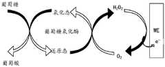
参照图36以及下述的化学式一、式二、式三以及式四对具有图35提供的涂层结构的工作电极的工作原理说明如下:皮下的组织液中溶解的氧气O2参与葡萄糖(glucose)氧化过程,与葡萄糖一起穿过生物相容性层和分析物调节层,到达葡萄糖氧化酶层发生反应。首先,葡萄糖氧化酶(GOx)催化葡萄糖(glucose)氧化成葡萄糖酸(gluconolactone),葡萄糖氧化酶从氧化态转变为还原态(如式一),其中该式一中以氧化态的黄素腺嘌呤二核苷酸(FAD)作为氧化剂提供氧气O2后还原为还原态的黄素腺嘌呤二核苷酸(FADH2),之后,氧气O2将还原态的葡萄糖氧化酶氧化,变成过氧化氢(H2O2)(如式二),式二中以还原态的黄素腺嘌呤二核苷酸(FADH2)被氧气O2氧化为氧化态的黄素腺嘌呤二核苷酸(FAD);其中,式一和式二等价为式三,即葡萄糖(glucose)与氧气O2在葡萄糖氧化酶GOx的催化作用下生成葡萄糖酸(gluconolactone)和氧化氢(H2O2)。最后,过氧化氢(H2O2)穿过抗干扰层,到达基底层,在工作电极的电压(0.6-0.7V)作用下发生氧化或还原反应,产生电流e-。36 and the following chemical formulas one, two, three and four, the working principle of the working electrode with the coating structure provided in FIG. 35 is explained as follows: the dissolved oxygenO2 in the subcutaneous tissue fluid participates in glucose (glucose) The oxidation process, together with glucose, passes through the biocompatibility layer and the analyte-modulating layer, and reaches the glucose oxidase layer to react. First, glucose oxidase (GOx) catalyzes the oxidation of glucose to gluconolactone, and the glucose oxidase changes from the oxidized state to the reduced state (as in formula 1), wherein the oxidized state of flavin adenine in
其中,工作电极的涂层包括但不限于上述的基底层、抗干扰层、酶传感层、分析物调节层(半透膜)、生物相容性层等等,各涂层顺序可能会微调(例如抗干扰层可以设置到分析物调节层和生物相容性层之间),或者某些涂层可能会混合成一层使用。Wherein, the coating of the working electrode includes but is not limited to the above-mentioned substrate layer, anti-interference layer, enzyme sensing layer, analyte regulating layer (semi-permeable membrane), biocompatibility layer, etc. The order of each coating may be fine-tuned (For example, an anti-interference layer may be interposed between the analyte modulating layer and the biocompatibility layer), or some coatings may be mixed into one layer for use.
GOx(FAD)+glucose→GOx(FADH2)+gluconolactone;式一。GOx(FAD)+glucose→GOx(FADH2 )+gluconolactone;
GOx(FADH2)+氧化剂(O2)→GOx(FAD)+产物(H2O2);式二。GOx(FADH2 )+oxidant (O2 )→GOx(FAD)+product (H2 O2 ); formula II.


在另一种方案中,参照图37所示,工作电极WE上依次层叠设置有基底层、氧化还原介质层、葡萄糖氧化酶层、抗干扰层、分析物调节层、生物相容性层。其中除氧化还原介质层外,其他各层的作用与材料可以参考图35对应的实施例中的描述。其中氧化还原介质层为基于锇络合物(Os)的高分子链装材料,其作用是在低电位下传递电子,降低(抗坏血酸、尿酸等)干扰物质影响。参照图38以及下述的化学式五、式六、式七以及式八对具有图37提供的涂层结构的工作电极的工作原理说明如下:与图35提供的方案的区别是氧气O2不参与氧化还原反应,氧化还原介质层取代氧气。首先,葡萄糖(glucose)穿过生物相容性层、分析物调节层和抗干扰层,到达葡萄糖氧化酶层,氧化型的葡萄糖(GOx)氧化酶催化葡萄糖氧化成葡萄糖酸(gluconolactone),自己被还原成还原型葡萄糖氧化酶((GOx)(如式五),其中该式五中以氧化态的黄素腺嘌呤二核苷酸(FAD)作为氧化剂提供氧气O2后还原为还原态的黄素腺嘌呤二核苷酸(FADH2);之后,氧化态的电子中间体(如络合物Os)将还原型的葡萄糖氧化酶氧化,自己变成还原态产物(如式六),式六中以还原态的黄素腺嘌呤二核苷酸(FADH2)被氧化态的电子中间体氧化为氧化态的黄素腺嘌呤二核苷酸(FAD);其中,式五和式六等价为式七,即葡萄糖(glucose)与氧化态的电子中间体(如络合物Os)在葡萄糖氧化酶GOx的催化作用下生成葡萄糖酸(gluconolactone)和还原态的电子中间体。最后,在工作电极WE上施加一个电压(由于采用了氧化还原介质层,氧气不参与反应,也没有过氧化氢生成。所以工作电极上施加很小的电压(0.2V)就可以完成电子传递),再次将还原态产物氧化,即可产生与葡萄糖浓度相应的电流。In another solution, as shown in FIG. 37 , a substrate layer, a redox mediator layer, a glucose oxidase layer, an anti-interference layer, an analyte regulating layer, and a biocompatibility layer are sequentially stacked on the working electrode WE. Except for the redox medium layer, the functions and materials of other layers may refer to the description in the corresponding embodiment of FIG. 35 . The redox mediator layer is a polymer chain-packed material based on osmium complex (Os), and its function is to transfer electrons at a low potential and reduce the influence of interfering substances (ascorbic acid, uric acid, etc.). Referring to Figure 38 and the following chemical formulae five, six, seven and eight, the working principle of the working electrode with the coating structure provided in Figure 37 is explained as follows: the difference from the scheme provided in Figure 35 is that oxygen O2 does not participate in A redox reaction, where the redox mediator layer replaces oxygen. First, glucose (glucose) passes through the biocompatibility layer, the analyte regulation layer and the anti-interference layer, and reaches the glucose oxidase layer. The oxidized glucose (GOx) oxidase catalyzes the oxidation of glucose to gluconolactone, which is itself Reduction to reduced glucose oxidase ((GOx) (such as formula five), wherein in the formula five, oxidized flavin adenine dinucleotide (FAD) is used as an oxidant to provide oxygenO2 and then reduced to reduced yellow Adenine dinucleotide (FADH2 ); after that, the oxidized electronic intermediate (such as complex Os) oxidizes the reduced glucose oxidase and turns itself into a reduced product (such as formula 6), formula 6 The flavin adenine dinucleotide (FADH2 ) in the reduced state is oxidized to the flavin adenine dinucleotide (FAD) in the oxidized state by the electron intermediate in the oxidized state; wherein, formula five and formula six are equivalent It is formula 7, that is, glucose and oxidized electronic intermediates (such as complex Os) are catalyzed by glucose oxidase GOx to generate gluconolactone and reduced electronic intermediates. Finally, in the work A voltage is applied to the electrode WE (due to the use of a redox medium layer, oxygen does not participate in the reaction, and no hydrogen peroxide is generated. Therefore, a small voltage (0.2V) is applied to the working electrode to complete electron transfer), and the reduction is performed again. The state product is oxidized, and a current corresponding to the glucose concentration can be generated.
在该方案中,工作电极上的涂层包括但不限于基底层、氧化还原介质层、酶传感层、抗干扰层、分析物调节层(半透膜)、生物相容性层等等,各涂层顺序可能会微调(例如抗干扰层可以设置到生物相容性层和分析物调节层之间),某些涂层可能会混合成一层使用。在该实施例中,由于氧气不参与反应,干扰物质对贴片的血糖检测带来干扰甚微,因此也可以省去抗干扰层。In this scheme, the coating on the working electrode includes, but is not limited to, a substrate layer, a redox mediator layer, an enzyme sensing layer, an anti-interference layer, an analyte-modulating layer (semi-permeable membrane), a biocompatibility layer, and the like, The order of individual coatings may be fine-tuned (eg, an anti-interference layer may be placed between a biocompatibility layer and an analyte modulating layer), and some coatings may be mixed and used in one layer. In this embodiment, since oxygen does not participate in the reaction, the interfering substances cause little interference to the blood glucose detection of the patch, so the anti-interference layer can also be omitted.
GOx(FAD)+glucose→GOx(FADH2)+gluconolactone;式五。GOx(FAD)+glucose→GOx(FADH2 )+gluconolactone; formula five.
GOx(FADH2)+Os(氧化态)→GOx(FAD)+Os(还原态);式六。GOx(FADH2 )+Os (oxidized state)→GOx(FAD)+Os (reduced state); formula VI.


基于上述的智能手表以及贴片,由于智能手表穿戴在人体的部位后,人体的运动智能手表自身会存在小幅度的扰动,这样当智能手表的扰动造成智能手表的外接接口与贴片的电极接口的连接断开时,可能会影响到生理参数检测的正常进行,因此为了确保智能手表佩戴在人体状态下智能手表20上的外接接口21与贴片10的电极接口12形成电连接,以保证正常的进行生理参数的检测。在本申请的实施例提供一种贴片的在位检测方法,参照图39所示,具体包括如下步骤:Based on the above-mentioned smart watch and patch, after the smart watch is worn on the human body, the sports smart watch of the human body will have a small disturbance, so when the disturbance of the smart watch causes the external interface of the smart watch and the electrode interface of the patch When the connection is disconnected, the normal detection of physiological parameters may be affected. Therefore, in order to ensure that the
101、智能手表获取电化学传感电路输出的检测信号。101. The smart watch obtains the detection signal output by the electrochemical sensing circuit.
其中该检测信号可以为电压或电流等具有一定信号强度的信号。The detection signal may be a signal with a certain signal strength, such as voltage or current.
102、当确定检测信号的强度小于或等于信号阈值时,智能手表生成第一提示信息,其中第一提示信息用于提示用户调整智能手表的佩戴位置。102. When it is determined that the strength of the detection signal is less than or equal to the signal threshold, the smart watch generates first prompt information, where the first prompt information is used to prompt the user to adjust the wearing position of the smart watch.
103、当确定检测信号的强度大于信号阈值时,智能手表生成第二提示信息,其中第二提示信息用于提示用户开始生理参数检测。103. When it is determined that the strength of the detection signal is greater than the signal threshold, the smart watch generates second prompt information, where the second prompt information is used to prompt the user to start the physiological parameter detection.
第一提示信息以及第二提示信息包括:振动、声音、或显示信息。The first prompt information and the second prompt information include: vibration, sound, or display information.
由于电化学传感电路输出的检测信号可以反应智能手表20上的外接接口21与贴片10的电极接口12的连接状态,例如如果检测信号的强度为零,则表明智能手表20上的外接接口21与贴片10的电极接口12完全断开,或者检测信号输出大于0但小于信号阈值,则说明智能手表20上的外接接口21与贴片10的电极接口12接触不良,存在高阻抗接触问题。此时需要通过调整智能手表20佩戴的姿态以使智能手表20上的外接接口21与贴片10的电极接口12重新电连接。Since the detection signal output by the electrochemical sensing circuit can reflect the connection state between the
具体的,以完整的血糖检测过程为例,对本申请的实施例提供的智能手表20以及贴片10的使用过程说明如下:首先,用户通过主动按压或助针器辅助植入的方式将贴片10贴敷于手腕背部;随后佩戴智能手表20。其中,正确佩戴完成后,智能手表20上的外接接口21与贴片10的电极接口12建立电连接。之后,通过手动启动或自动启动的方式,开启血糖检测功能。Specifically, taking the complete blood glucose detection process as an example, the use process of the
示例性地,智能手表20可以显示第一界面,并接收用户对第一界面的第一操作。该第一操作用于触发智能手表20进行血糖检测。具体的,智能手表20可以显示第一APP的第一界面。其中,第一界面可以用于触发智能手表20进行血糖检测。例如该第一界面可以显示“测血糖”的触发标识,指示用户可以通过点击该“测血糖”的标识触发血糖检测。此外,还可以进一步触发血糖检测的模式,例如单次检测模式或者连续检测模式,在连续检测模式下进一步可以配置检测时间间隔等参数。Exemplarily, the
例如,本申请实施例中的第一APP可以为如图40中所示的图标“健康”对应的应用。如图40中所示,智能手表20可接收用户对图标“健康”的点击操作;响应于该点击操作,智能手表20可启动第一APP,显示图41中的第一APP的首页(即第一界面411)。第一界面411中可以包括一个健康管理选项,如“测血糖”选项(第一界面411中的控件4111),控件4111用于触发智能手表测血糖。上述第一操作可以是用户对第一界面411中所示的控件4111的点击操作(如单击操作),例如对控件4111的点击操作。或者,上述第一操作还可以是用户在第一界面411(如图41所示)中输入的预设手势,如S形手势,L形手势,双指向上滑动手势或者三指向上滑动手势等。并且,智能手表20可以在第一界面向用户提示该预设手势,以及该预设手势所触发的功能(即测血糖)。For example, the first APP in this embodiment of the present application may be an application corresponding to the icon "health" as shown in FIG. 40 . As shown in FIG. 40 , the
具体的,当用户点击控件4111时,响应于用户对控件4111的点击操作,智能手表20显示第二界面421(如图42所示,第二界面421中显示“正在测血糖”向用户提示智能手表20正在进行血糖检测),其中,智能手表20显示第二界面421的过程中,智能手表20向贴片10的工作电极和参比电极之间施加恒定电压,开始正式的血糖检测。此时,工作电极的涂层会催化葡萄糖氧化,产生电信号,手表内的电化学传感电路可以捕获电信号,转换成检测信号,最后智能手表20的处理器通过算法对检测信号进行信号处理和分析,转换成葡萄糖浓度(血糖值)。此外,在智能手表20显示第二界面421之后,还可以首先对贴片10进行初始化(其中,微针刚插入体内的一段时间(1个小时到几个小时不等),表面膜层会充水,又叫水合过程,之后才能恢复稳定,该过程为贴片10的初始化),并执行校准算法或者提醒用户通过指尖血糖进行校准。在生成测量结果后,智能手表20显示第三界面431(如图43所示,第三界面431上显示“当前血糖:6.0mg/dL),当然第三界面431上还可以提供用于提示用户通过点击操作触发对“之前的测量值”(控件4311)进行查询的选项。此外,第一界面411中还可以包括“模式设置”(控件4112)等选项。其中,对于图41示出的第一界面411中的控件4112,当用户对控件4112进行点击操作后,智能手表20显示第四界面441(如图44所示),在该第四界面441可以提供用于提示用户触发“连续检测模式”(控件4411)或“单次检测模式”(控件4412)的选项,响应于对控件4411或控件4412的点击操作,智能手表20可以进入对应的检测模式,例如响应于控件4412的点击操作,智能手表20进入单次检测模式,并完成单次血糖测量;响应于控件4411的点击操作,智能手表20进入在连续检测模式,可以在用户配置的时间间隔下连续进行血糖测量。以上结合一个具体的示例提供了一次完整的血糖检测过程,其中,实际使用过程中,由于智能手表穿戴在人体的部位后,人体的运动造成智能手表自身会存在小幅度的扰动,这样当智能手表的扰动造成智能手表的外接接口与贴片的电极接口的连接断开时,可能会影响到血糖检测的正常进行,因此在用户在第一界面411点击控件4111之后,智能手表获取电化学传感电路输出的检测信号。例如可以是电流信号,当确定检测信号的电流强度小于或等于信号阈值时(例如电流强度为零或者小于信号阈值),生成第一提示信息,例如可以是向用户展示第五界面451(如图45所示,具体第五界面451显示内容可以是“电极未接触,请调整设备位置”),当然该第一提示信息也可以是驱动振动电机291发出的振动,或者通过扬声器270A发出的语音提示,或者三者中任意两者或三者的结合。这样,当用户根据提示调整位置后,智能手表持续获取电化学传感电路输出的检测信号,直至确定检测信号的强度大于信号阈值时,生成第二提示信息,其中第二提示信息用于提示用户开始血糖检测。示例性的该第二提示信息可以直接复用上述的第二界面421(如图42所示),当然也可以同时提供语音或震动提示。Specifically, when the user clicks on the
示例性地,图46为本申请实施例提供的一种电子设备的结构示意图,该电子设备可以具体实现上述图39中所示出的方法。Exemplarily, FIG. 46 is a schematic structural diagram of an electronic device provided by an embodiment of the present application, and the electronic device can specifically implement the method shown in the foregoing FIG. 39 .
如图46所示,该电子设备20包括:信号检测模块201、信号处理模块202。上述模块或组件可以通过一根或者多根通信总线(I2C)或信号线进行通信。本领域技术人员可以理解,图46中示出的模块或组件并不构成对电子设备的限定,电子设备20可以包括比图示更多或更少的部件,或者组合某些部件,或者不同的部件布置。As shown in FIG. 46 , the
信号检测模块201,用于根据电化学传感电路输出的检测信号,确定贴片的连接状态。信号处理模块202,用于当确定信号检测模块201获取的检测信号的强度小于或等于信号阈值时,生成第一提示信息,其中第一提示信息用于提示用户调整电子设备的佩戴位置。The
可选的,信号处理模块202,还用于当确定检测信号的强度大于信号阈值时,生成第二提示信息,其中第二提示信息用于提示用户开始生理参数检测。第一提示信息以及第二提示信息包括:振动、声音、或显示信息。Optionally, the
本申请另一些实施例提供了一种电子设备,该电子设备可以包括:上述显示屏(如触摸屏)、存储器和一个或多个处理器。该显示屏、存储器和处理器耦合。该存储器用于存储计算机程序代码,该计算机程序代码包括计算机指令。当处理器执行计算机指令时,电子设备可执行上述方法实施例中电子设备执行的各个功能或者步骤。该电子设备的结构可以参考图2所示的电子设备20的结构。Other embodiments of the present application provide an electronic device, which may include: the above-mentioned display screen (eg, a touch screen), a memory, and one or more processors. The display screen, memory and processor are coupled. The memory is used to store computer program code comprising computer instructions. When the processor executes the computer instructions, the electronic device can perform various functions or steps performed by the electronic device in the foregoing method embodiments. For the structure of the electronic device, reference may be made to the structure of the
本申请实施例还提供一种芯片系统,如图47所示,该芯片系统30包括至少一个处理器301和至少一个接口电路302。处理器301和接口电路302可通过线路互联。例如,接口电路302可用于从其它装置(例如电子设备的存储器)接收信号。又例如,接口电路302可用于向其它装置(例如处理器301)发送信号。示例性的,接口电路302可读取存储器中存储的指令,并将该指令发送给处理器301。当该指令被处理器301执行时,可使得电子设备执行上述实施例中的各个步骤。当然,该芯片系统还可以包含其他分立器件,本申请实施例对此不作具体限定。This embodiment of the present application further provides a chip system. As shown in FIG. 47 , the
本申请实施例还提供一种计算机可读存储介质,该计算机可读存储介质包括计算机指令,当上述计算机指令在上述电子设备上运行时,使得该电子设备执行上述方法实施例中电子设备执行的各个功能或者步骤。Embodiments of the present application further provide a computer-readable storage medium, where the computer-readable storage medium includes computer instructions, when the computer instructions are executed on the electronic device, the electronic device is made to execute the execution of the electronic device in the foregoing method embodiments. Each function or step.
本申请实施例还提供一种计算机程序产品,当该计算机程序产品在计算机上运行时,使得上述计算机执行上述方法实施例中电子设备执行的各个功能或者步骤。Embodiments of the present application further provide a computer program product, which, when the computer program product runs on a computer, enables the computer to perform each function or step performed by the electronic device in the above method embodiments.
通过以上实施方式的描述,所属领域的技术人员可以清楚地了解到,为描述的方便和简洁,仅以上述各功能模块的划分进行举例说明,实际应用中,可以根据需要而将上述功能分配由不同的功能模块完成,即将装置的内部结构划分成不同的功能模块,以完成以上描述的全部或者部分功能。From the description of the above embodiments, those skilled in the art can clearly understand that, for the convenience and brevity of the description, only the division of the above functional modules is used as an example for illustration. In practical applications, the above functions can be allocated by Different functional modules are completed, that is, the internal structure of the device is divided into different functional modules, so as to complete all or part of the functions described above.
在本申请所提供的几个实施例中,应该理解到,所揭露的装置和方法,可以通过其它的方式实现。例如,以上所描述的装置实施例仅仅是示意性的,例如,上述模块或单元的划分,仅仅为一种逻辑功能划分,实际实现时可以有另外的划分方式,例如多个单元或组件可以结合或者可以集成到另一个装置,或一些特征可以忽略,或不执行。另一点,所显示或讨论的相互之间的耦合或直接耦合或通信连接可以是通过一些接口,装置或单元的间接耦合或通信连接,可以是电性,机械或其它的形式。In the several embodiments provided in this application, it should be understood that the disclosed apparatus and method may be implemented in other manners. For example, the device embodiments described above are only illustrative. For example, the above-mentioned division of modules or units is only a logical function division. In actual implementation, there may be other division methods. For example, multiple units or components may be combined. Or it may be integrated into another device, or some features may be omitted, or not implemented. On the other hand, the shown or discussed mutual coupling or direct coupling or communication connection may be through some interfaces, indirect coupling or communication connection of devices or units, and may be in electrical, mechanical or other forms.
作为分离部件说明的单元可以是或者也可以不是物理上分开的,作为单元显示的部件可以是一个物理单元或多个物理单元,即可以位于一个地方,或者也可以分布到多个不同地方。可以根据实际的需要选择其中的部分或者全部单元来实现本实施例方案的目的。Units described as separate components may or may not be physically separated, and components shown as units may be one physical unit or multiple physical units, that is, may be located in one place, or may be distributed in multiple different places. Some or all of the units may be selected according to actual needs to achieve the purpose of the solution in this embodiment.
另外,在本申请各个实施例中的各功能单元可以集成在一个处理单元中,也可以是各个单元单独物理存在,也可以两个或两个以上单元集成在一个单元中。上述集成的单元既可以采用硬件的形式实现,也可以采用软件功能单元的形式实现。In addition, each functional unit in each embodiment of the present application may be integrated into one processing unit, or each unit may exist physically alone, or two or more units may be integrated into one unit. The above-mentioned integrated units may be implemented in the form of hardware, or may be implemented in the form of software functional units.
集成的单元如果以软件功能单元的形式实现并作为独立的产品销售或使用时,可以存储在一个可读取存储介质中。基于这样的理解,本申请实施例的技术方案本质上或者说对现有技术做出贡献的部分或者该技术方案的全部或部分可以以软件产品的形式体现出来,该软件产品存储在一个存储介质中,包括若干指令用以使得一个设备(可以是单片机,芯片等)或处理器(processor)执行本申请各个实施例中方法的全部或部分步骤。而前述的存储介质包括:U盘、移动硬盘、只读存储器(read only memory,ROM)、随机存取存储器(random access memory,RAM)、磁碟或者光盘等各种可以存储程序代码的介质。The integrated unit, if implemented in the form of a software functional unit and sold or used as a stand-alone product, may be stored in a readable storage medium. Based on such understanding, the technical solutions of the embodiments of the present application can be embodied in the form of software products in essence, or the parts that contribute to the prior art, or all or part of the technical solutions, which are stored in a storage medium , including several instructions to make a device (which may be a single chip microcomputer, a chip, etc.) or a processor (processor) to execute all or part of the steps of the methods in the various embodiments of the present application. The aforementioned storage medium includes: a U disk, a removable hard disk, a read only memory (ROM), a random access memory (RAM), a magnetic disk or an optical disk and other media that can store program codes.
以上内容,仅为本申请的具体实施方式,但本申请的保护范围并不局限于此,任何在本申请揭露的技术范围内的变化或替换,都应涵盖在本申请的保护范围之内。因此,本申请的保护范围应以权利要求的保护范围为准。The above contents are only specific embodiments of the present application, but the protection scope of the present application is not limited thereto, and any changes or substitutions within the technical scope disclosed in the present application should be covered within the protection scope of the present application. Therefore, the protection scope of the present application shall be subject to the protection scope of the claims.
Claims (33)
Translated fromChinesePriority Applications (3)
| Application Number | Priority Date | Filing Date | Title |
|---|---|---|---|
| CN202110461872.8ACN115245332B (en) | 2021-04-27 | 2021-04-27 | Electronic equipment, patch and detection systems |
| PCT/CN2022/083850WO2022227999A1 (en) | 2021-04-27 | 2022-03-29 | Electronic device, patch and measuring system |
| EP22794472.5AEP4309569A4 (en) | 2021-04-27 | 2022-03-29 | ELECTRONIC DEVICE, PATCH AND MEASURING SYSTEM |
Applications Claiming Priority (1)
| Application Number | Priority Date | Filing Date | Title |
|---|---|---|---|
| CN202110461872.8ACN115245332B (en) | 2021-04-27 | 2021-04-27 | Electronic equipment, patch and detection systems |
Publications (2)
| Publication Number | Publication Date |
|---|---|
| CN115245332Atrue CN115245332A (en) | 2022-10-28 |
| CN115245332B CN115245332B (en) | 2025-10-03 |
Family
ID=83695899
Family Applications (1)
| Application Number | Title | Priority Date | Filing Date |
|---|---|---|---|
| CN202110461872.8AActiveCN115245332B (en) | 2021-04-27 | 2021-04-27 | Electronic equipment, patch and detection systems |
Country Status (3)
| Country | Link |
|---|---|
| EP (1) | EP4309569A4 (en) |
| CN (1) | CN115245332B (en) |
| WO (1) | WO2022227999A1 (en) |
Cited By (2)
| Publication number | Priority date | Publication date | Assignee | Title |
|---|---|---|---|---|
| CN118557188A (en)* | 2023-02-28 | 2024-08-30 | 华为技术有限公司 | Electronic devices |
| CN119970023A (en)* | 2025-03-25 | 2025-05-13 | 歌尔股份有限公司 | Blood glucose testing device |
Families Citing this family (1)
| Publication number | Priority date | Publication date | Assignee | Title |
|---|---|---|---|---|
| CN120227022A (en)* | 2023-12-29 | 2025-07-01 | 华为技术有限公司 | Measurement method, system and related device |
Citations (6)
| Publication number | Priority date | Publication date | Assignee | Title |
|---|---|---|---|---|
| WO2012145027A1 (en)* | 2011-04-20 | 2012-10-26 | Abbott Diabetes Care Inc. | Analyte monitoring devices and methods |
| CN106102578A (en)* | 2014-03-13 | 2016-11-09 | 萨诺智能公司 | System for monitoring body chemistry |
| CN110049713A (en)* | 2016-10-12 | 2019-07-23 | Dst创新有限公司 | Electronics biological identification device and its building method |
| EP3171768B1 (en)* | 2014-08-01 | 2020-09-16 | LifeLens Technologies, LLC | Modular physiologic monitoring systems |
| CN112105294A (en)* | 2018-04-30 | 2020-12-18 | 三星电子株式会社 | Electronic device for detecting biological information |
| CN112617749A (en)* | 2019-11-19 | 2021-04-09 | 奇异平台股份有限公司 | Physiological and biochemical monitoring device |
Family Cites Families (5)
| Publication number | Priority date | Publication date | Assignee | Title |
|---|---|---|---|---|
| US9545204B2 (en)* | 2013-09-25 | 2017-01-17 | Bardy Diagnostics, Inc. | Extended wear electrocardiography patch |
| TWI519781B (en)* | 2014-01-28 | 2016-02-01 | 微凸科技股份有限公司 | Transdermal microneedle array patch |
| JP7628953B2 (en)* | 2018-10-02 | 2025-02-12 | ウェアオプティモ ピーティーワイ リミテッド | Electrode Equipment |
| US20220257181A1 (en)* | 2019-07-23 | 2022-08-18 | The Regents Of The University Of California | Minimally invasive continuous analyte monitoring for closed-loop treatment applications |
| CN110522460A (en)* | 2019-09-29 | 2019-12-03 | 清华大学深圳国际研究生院 | Multi-index detection sensor based on transdermal microneedle array and preparation method |
- 2021
- 2021-04-27CNCN202110461872.8Apatent/CN115245332B/enactiveActive
- 2022
- 2022-03-29WOPCT/CN2022/083850patent/WO2022227999A1/ennot_activeCeased
- 2022-03-29EPEP22794472.5Apatent/EP4309569A4/enactivePending
Patent Citations (6)
| Publication number | Priority date | Publication date | Assignee | Title |
|---|---|---|---|---|
| WO2012145027A1 (en)* | 2011-04-20 | 2012-10-26 | Abbott Diabetes Care Inc. | Analyte monitoring devices and methods |
| CN106102578A (en)* | 2014-03-13 | 2016-11-09 | 萨诺智能公司 | System for monitoring body chemistry |
| EP3171768B1 (en)* | 2014-08-01 | 2020-09-16 | LifeLens Technologies, LLC | Modular physiologic monitoring systems |
| CN110049713A (en)* | 2016-10-12 | 2019-07-23 | Dst创新有限公司 | Electronics biological identification device and its building method |
| CN112105294A (en)* | 2018-04-30 | 2020-12-18 | 三星电子株式会社 | Electronic device for detecting biological information |
| CN112617749A (en)* | 2019-11-19 | 2021-04-09 | 奇异平台股份有限公司 | Physiological and biochemical monitoring device |
Cited By (3)
| Publication number | Priority date | Publication date | Assignee | Title |
|---|---|---|---|---|
| CN118557188A (en)* | 2023-02-28 | 2024-08-30 | 华为技术有限公司 | Electronic devices |
| WO2024179186A1 (en)* | 2023-02-28 | 2024-09-06 | 华为技术有限公司 | Electronic device |
| CN119970023A (en)* | 2025-03-25 | 2025-05-13 | 歌尔股份有限公司 | Blood glucose testing device |
Also Published As
| Publication number | Publication date |
|---|---|
| EP4309569A1 (en) | 2024-01-24 |
| EP4309569A4 (en) | 2024-11-13 |
| CN115245332B (en) | 2025-10-03 |
| WO2022227999A1 (en) | 2022-11-03 |
Similar Documents
| Publication | Publication Date | Title |
|---|---|---|
| WO2022227999A1 (en) | Electronic device, patch and measuring system | |
| CN105873514B (en) | Dynamic glucose harvester and host | |
| JP2021072907A (en) | Re-attachment type wireless device | |
| EP2146622B1 (en) | Method and apparatus for providing dynamic multi-stage signal amplification in a medical device | |
| WO2020253727A1 (en) | Ecg monitoring method and wearable device | |
| KR20160149911A (en) | Method for measuring biological information, and electronic device performing thereof | |
| JP2024544044A (en) | Continuous Cortisol Monitoring System with Microneedle Array | |
| ES2626049T3 (en) | Analytical test strip with integrated battery | |
| ES2739076T3 (en) | Digital detection of samples by analyte meter | |
| EP3745955B1 (en) | Electronic device for detecting biometric information | |
| EP4291091B1 (en) | Network physical layer configurations for ambulatory physiological parameter monitoring and therapeutic intervention systems | |
| Ghazizadeh et al. | Approaches of wearable and implantable biosensor towards of developing in precision medicine | |
| WO2017092169A1 (en) | Dynamic blood glucose monitoring device, system and method | |
| CN204351841U (en) | Portable dynamic blood-sugar detecting instrument main frame | |
| CN215415184U (en) | Electrochemical sensor detection circuit, device and system | |
| Quero et al. | Health care applications based on mobile phone centric smart sensor network | |
| CN112826454B (en) | Information pushing method and related product | |
| CN222841020U (en) | Glucose concentration detection device and in-vivo glucose monitoring system | |
| RU163942U1 (en) | MEDICAL TRANSMITTER | |
| EP4613192A1 (en) | Blood glucose measurement method, electronic device, and system | |
| EP4513510A1 (en) | Blood glucose assessment method, electronic device, and computer readable storage medium | |
| Yang et al. | A miniaturized glucose biosensor for in vitro and in vivo studies | |
| CN120227022A (en) | Measurement method, system and related device | |
| WO2025140657A1 (en) | Measurement method and system and related apparatus | |
| CN118266918A (en) | Blood glucose measuring method, electronic equipment and system |
Legal Events
| Date | Code | Title | Description |
|---|---|---|---|
| PB01 | Publication | ||
| PB01 | Publication | ||
| SE01 | Entry into force of request for substantive examination | ||
| SE01 | Entry into force of request for substantive examination | ||
| GR01 | Patent grant |