CN115243631A - Method and apparatus for endoscopic resection - Google Patents
Method and apparatus for endoscopic resectionDownload PDFInfo
- Publication number
- CN115243631A CN115243631ACN202180019523.9ACN202180019523ACN115243631ACN 115243631 ACN115243631 ACN 115243631ACN 202180019523 ACN202180019523 ACN 202180019523ACN 115243631 ACN115243631 ACN 115243631A
- Authority
- CN
- China
- Prior art keywords
- lesion
- central portion
- resection
- snare
- catheter
- Prior art date
- Legal status (The legal status is an assumption and is not a legal conclusion. Google has not performed a legal analysis and makes no representation as to the accuracy of the status listed.)
- Pending
Links
Images


Classifications
- A—HUMAN NECESSITIES
- A61—MEDICAL OR VETERINARY SCIENCE; HYGIENE
- A61B—DIAGNOSIS; SURGERY; IDENTIFICATION
- A61B18/00—Surgical instruments, devices or methods for transferring non-mechanical forms of energy to or from the body
- A61B18/04—Surgical instruments, devices or methods for transferring non-mechanical forms of energy to or from the body by heating
- A61B18/12—Surgical instruments, devices or methods for transferring non-mechanical forms of energy to or from the body by heating by passing a current through the tissue to be heated, e.g. high-frequency current
- A61B18/14—Probes or electrodes therefor
- A61B18/1477—Needle-like probes
- A—HUMAN NECESSITIES
- A61—MEDICAL OR VETERINARY SCIENCE; HYGIENE
- A61B—DIAGNOSIS; SURGERY; IDENTIFICATION
- A61B17/00—Surgical instruments, devices or methods
- A61B17/02—Surgical instruments, devices or methods for holding wounds open, e.g. retractors; Tractors
- A61B17/0218—Surgical instruments, devices or methods for holding wounds open, e.g. retractors; Tractors for minimally invasive surgery
- A—HUMAN NECESSITIES
- A61—MEDICAL OR VETERINARY SCIENCE; HYGIENE
- A61B—DIAGNOSIS; SURGERY; IDENTIFICATION
- A61B17/00—Surgical instruments, devices or methods
- A61B17/00234—Surgical instruments, devices or methods for minimally invasive surgery
- A—HUMAN NECESSITIES
- A61—MEDICAL OR VETERINARY SCIENCE; HYGIENE
- A61B—DIAGNOSIS; SURGERY; IDENTIFICATION
- A61B17/00—Surgical instruments, devices or methods
- A61B17/12—Surgical instruments, devices or methods for ligaturing or otherwise compressing tubular parts of the body, e.g. blood vessels or umbilical cord
- A61B17/12009—Implements for ligaturing other than by clamps or clips, e.g. using a loop with a slip knot
- A61B17/12013—Implements for ligaturing other than by clamps or clips, e.g. using a loop with a slip knot for use in minimally invasive surgery, e.g. endoscopic surgery
- A—HUMAN NECESSITIES
- A61—MEDICAL OR VETERINARY SCIENCE; HYGIENE
- A61B—DIAGNOSIS; SURGERY; IDENTIFICATION
- A61B18/00—Surgical instruments, devices or methods for transferring non-mechanical forms of energy to or from the body
- A61B18/04—Surgical instruments, devices or methods for transferring non-mechanical forms of energy to or from the body by heating
- A61B18/12—Surgical instruments, devices or methods for transferring non-mechanical forms of energy to or from the body by heating by passing a current through the tissue to be heated, e.g. high-frequency current
- A61B18/14—Probes or electrodes therefor
- A61B18/1492—Probes or electrodes therefor having a flexible, catheter-like structure, e.g. for heart ablation
- A—HUMAN NECESSITIES
- A61—MEDICAL OR VETERINARY SCIENCE; HYGIENE
- A61B—DIAGNOSIS; SURGERY; IDENTIFICATION
- A61B17/00—Surgical instruments, devices or methods
- A61B17/00234—Surgical instruments, devices or methods for minimally invasive surgery
- A61B2017/00238—Type of minimally invasive operation
- A61B2017/00269—Type of minimally invasive operation endoscopic mucosal resection EMR
- A—HUMAN NECESSITIES
- A61—MEDICAL OR VETERINARY SCIENCE; HYGIENE
- A61B—DIAGNOSIS; SURGERY; IDENTIFICATION
- A61B17/00—Surgical instruments, devices or methods
- A61B17/00234—Surgical instruments, devices or methods for minimally invasive surgery
- A61B2017/00292—Surgical instruments, devices or methods for minimally invasive surgery mounted on or guided by flexible, e.g. catheter-like, means
- A61B2017/00296—Surgical instruments, devices or methods for minimally invasive surgery mounted on or guided by flexible, e.g. catheter-like, means mounted on an endoscope
- A—HUMAN NECESSITIES
- A61—MEDICAL OR VETERINARY SCIENCE; HYGIENE
- A61B—DIAGNOSIS; SURGERY; IDENTIFICATION
- A61B17/00—Surgical instruments, devices or methods
- A61B2017/00477—Coupling
- A—HUMAN NECESSITIES
- A61—MEDICAL OR VETERINARY SCIENCE; HYGIENE
- A61B—DIAGNOSIS; SURGERY; IDENTIFICATION
- A61B17/00—Surgical instruments, devices or methods
- A61B2017/00831—Material properties
- A61B2017/00867—Material properties shape memory effect
- A—HUMAN NECESSITIES
- A61—MEDICAL OR VETERINARY SCIENCE; HYGIENE
- A61B—DIAGNOSIS; SURGERY; IDENTIFICATION
- A61B17/00—Surgical instruments, devices or methods
- A61B2017/00831—Material properties
- A61B2017/00876—Material properties magnetic
- A—HUMAN NECESSITIES
- A61—MEDICAL OR VETERINARY SCIENCE; HYGIENE
- A61B—DIAGNOSIS; SURGERY; IDENTIFICATION
- A61B17/00—Surgical instruments, devices or methods
- A61B2017/00831—Material properties
- A61B2017/00929—Material properties isolating electrical current
- A—HUMAN NECESSITIES
- A61—MEDICAL OR VETERINARY SCIENCE; HYGIENE
- A61B—DIAGNOSIS; SURGERY; IDENTIFICATION
- A61B17/00—Surgical instruments, devices or methods
- A61B17/02—Surgical instruments, devices or methods for holding wounds open, e.g. retractors; Tractors
- A61B17/0218—Surgical instruments, devices or methods for holding wounds open, e.g. retractors; Tractors for minimally invasive surgery
- A61B2017/0225—Surgical instruments, devices or methods for holding wounds open, e.g. retractors; Tractors for minimally invasive surgery flexible, e.g. fabrics, meshes, or membranes
- A—HUMAN NECESSITIES
- A61—MEDICAL OR VETERINARY SCIENCE; HYGIENE
- A61B—DIAGNOSIS; SURGERY; IDENTIFICATION
- A61B18/00—Surgical instruments, devices or methods for transferring non-mechanical forms of energy to or from the body
- A61B2018/00005—Cooling or heating of the probe or tissue immediately surrounding the probe
- A61B2018/00011—Cooling or heating of the probe or tissue immediately surrounding the probe with fluids
- A—HUMAN NECESSITIES
- A61—MEDICAL OR VETERINARY SCIENCE; HYGIENE
- A61B—DIAGNOSIS; SURGERY; IDENTIFICATION
- A61B18/00—Surgical instruments, devices or methods for transferring non-mechanical forms of energy to or from the body
- A61B2018/00005—Cooling or heating of the probe or tissue immediately surrounding the probe
- A61B2018/00041—Heating, e.g. defrosting
- A—HUMAN NECESSITIES
- A61—MEDICAL OR VETERINARY SCIENCE; HYGIENE
- A61B—DIAGNOSIS; SURGERY; IDENTIFICATION
- A61B18/00—Surgical instruments, devices or methods for transferring non-mechanical forms of energy to or from the body
- A61B2018/00571—Surgical instruments, devices or methods for transferring non-mechanical forms of energy to or from the body for achieving a particular surgical effect
- A61B2018/00595—Cauterization
- A—HUMAN NECESSITIES
- A61—MEDICAL OR VETERINARY SCIENCE; HYGIENE
- A61B—DIAGNOSIS; SURGERY; IDENTIFICATION
- A61B18/00—Surgical instruments, devices or methods for transferring non-mechanical forms of energy to or from the body
- A61B2018/00571—Surgical instruments, devices or methods for transferring non-mechanical forms of energy to or from the body for achieving a particular surgical effect
- A61B2018/00601—Cutting
- A—HUMAN NECESSITIES
- A61—MEDICAL OR VETERINARY SCIENCE; HYGIENE
- A61B—DIAGNOSIS; SURGERY; IDENTIFICATION
- A61B18/00—Surgical instruments, devices or methods for transferring non-mechanical forms of energy to or from the body
- A61B2018/00982—Surgical instruments, devices or methods for transferring non-mechanical forms of energy to or from the body combined with or comprising means for visual or photographic inspections inside the body, e.g. endoscopes
- A—HUMAN NECESSITIES
- A61—MEDICAL OR VETERINARY SCIENCE; HYGIENE
- A61B—DIAGNOSIS; SURGERY; IDENTIFICATION
- A61B18/00—Surgical instruments, devices or methods for transferring non-mechanical forms of energy to or from the body
- A61B18/04—Surgical instruments, devices or methods for transferring non-mechanical forms of energy to or from the body by heating
- A61B2018/044—Surgical instruments, devices or methods for transferring non-mechanical forms of energy to or from the body by heating the surgical action being effected by a circulating hot fluid
- A61B2018/046—Surgical instruments, devices or methods for transferring non-mechanical forms of energy to or from the body by heating the surgical action being effected by a circulating hot fluid in liquid form
- A—HUMAN NECESSITIES
- A61—MEDICAL OR VETERINARY SCIENCE; HYGIENE
- A61B—DIAGNOSIS; SURGERY; IDENTIFICATION
- A61B18/00—Surgical instruments, devices or methods for transferring non-mechanical forms of energy to or from the body
- A61B18/04—Surgical instruments, devices or methods for transferring non-mechanical forms of energy to or from the body by heating
- A61B18/12—Surgical instruments, devices or methods for transferring non-mechanical forms of energy to or from the body by heating by passing a current through the tissue to be heated, e.g. high-frequency current
- A61B18/14—Probes or electrodes therefor
- A61B2018/1405—Electrodes having a specific shape
- A61B2018/1412—Blade
Landscapes
- Health & Medical Sciences (AREA)
- Surgery (AREA)
- Life Sciences & Earth Sciences (AREA)
- Engineering & Computer Science (AREA)
- Molecular Biology (AREA)
- Biomedical Technology (AREA)
- Heart & Thoracic Surgery (AREA)
- Medical Informatics (AREA)
- Nuclear Medicine, Radiotherapy & Molecular Imaging (AREA)
- Animal Behavior & Ethology (AREA)
- General Health & Medical Sciences (AREA)
- Public Health (AREA)
- Veterinary Medicine (AREA)
- Physics & Mathematics (AREA)
- Plasma & Fusion (AREA)
- Otolaryngology (AREA)
- Surgical Instruments (AREA)
Abstract
Description
Translated fromChinese对相关申请的引用Citations to Related Applications
本申请要求于2020年1月7日提交的名称为“用于内窥镜下切除的方法和装置”的第62/957,954号美国专利临时申请的优先权,该临时申请的全部内容通过引用并入本文。This application claims priority to US Patent Provisional Application No. 62/957,954, filed January 7, 2020, entitled "Methods and Devices for Endoscopic Resection," which is incorporated by reference in its entirety. into this article.
技术领域technical field
本说明书总体上涉及内窥镜检查领域。更具体地说,本说明书涉及一种用于进行内窥镜下切除的装置和方法。This specification relates generally to the field of endoscopy. More specifically, the present specification relates to a device and method for performing endoscopic resection.
背景技术Background technique
内窥镜黏膜切除术(EMR)或内窥镜全层切除术(EFTR)是一种用于从消化道的内层去除早期癌症和癌前生长物的手术。内窥镜粘膜或全层切除通常使用配有灯和摄像头的长且窄的管进行。在上消化道的EMR或EFTR期间,临床医生使内窥镜向下穿过患者的喉咙,进入食道、胃或小肠的上部(十二指肠)。为了到达结肠,临床医生可以引导导管向上穿过肛门。然后,临床医生通过导管插入器械以进行各种切除手术。Endoscopic mucosal resection (EMR) or endoscopic full-thickness resection (EFTR) is a procedure used to remove early cancer and precancerous growths from the lining of the digestive tract. Endoscopic mucosal or full-thickness ablation is usually performed using a long, narrow tube equipped with a light and camera. During EMR or EFTR of the upper gastrointestinal tract, clinicians pass the endoscope down the patient's throat, into the esophagus, stomach, or the upper part of the small intestine (duodenum). To reach the colon, the clinician can guide the catheter up through the anus. Clinicians then insert instruments through the catheter to perform various resection procedures.
EMR或EFTR通常用于治疗健康状况或者在诊断过程中收集组织样本。EMR或EFTR是用于从消化道或消化道内壁去除异常组织的外科手术的侵入性较小的替代方案。EMR or EFTR is often used to treat medical conditions or to collect tissue samples during diagnosis. EMR or EFTR is a less invasive alternative to surgery to remove abnormal tissue from the digestive tract or the lining of the digestive tract.
发明内容SUMMARY OF THE INVENTION
以下实施例和其特征是与系统、工具和方法结合说明和示出的,它们仅是示例性和示意性的,而不构成对本发明的范围的限制。本申请公开了许多实施例。The following embodiments and their features are described and illustrated in conjunction with systems, tools, and methods, are exemplary and explanatory only, and do not limit the scope of the invention. This application discloses a number of embodiments.
本说明书公开了一种用于进行内窥镜下切除的装置,该装置包括:第一构件,其中该第一构件包括至少一个用于刺穿患者体内的病灶上的第一位置的第一穿刺末端;第二构件,其中该第二构件包括至少一个用于刺穿患者体内的病灶上的第二位置的第二穿刺末端;以及具有第一端和第二端的中央部分,其中所述第一构件附接至中央部分的第一端,所述第二构件附接至中央部分的第二端,其中所述中央部分配置成从第一直线形态变形为第二卷绕形态,其中,在将所述装置附着至病灶时,所述至少一个第一构件配置成抓住所述第一位置,所述至少一个第二构件配置成抓住所述第二位置,并且所述中央部分配置成从所述第一直线形态变形为所述第二卷绕形态以进行收缩,从而压缩所述病灶并减小所述病灶的至少一个尺寸。The present specification discloses a device for performing endoscopic resection, the device comprising: a first member, wherein the first member comprises at least one first puncture for penetrating a first location on a lesion in a patient a tip; a second member, wherein the second member includes at least one second piercing tip for piercing a second location on a lesion in a patient; and a central portion having a first end and a second end, wherein the first A member is attached to the first end of the central portion and the second member is attached to the second end of the central portion, wherein the central portion is configured to deform from a first linear configuration to a second coiled configuration, wherein the When attaching the device to the lesion, the at least one first member is configured to grasp the first position, the at least one second member is configured to grasp the second position, and the central portion is configured to grasp the second position Deforming from the first straight configuration to the second coiled configuration to shrink, thereby compressing the lesion and reducing at least one dimension of the lesion.
可选地,所述第一构件和所述第二构件分别包括钩。Optionally, the first member and the second member each comprise hooks.
可选地,所述装置还包括配置成包含该装置并将中央部分保持在第一直线形态的部署导管。可选地,所述中央部分配置成在从部署导管出来时变形为第二卷绕形态。Optionally, the device further includes a deployment catheter configured to contain the device and maintain the central portion in the first linear configuration. Optionally, the central portion is configured to deform into the second coiled configuration upon exiting the deployment catheter.
可选地,所述中央部分包括弹簧、线圈或弹性带中的至少一种。Optionally, the central portion includes at least one of a spring, coil or elastic band.
可选地,所述中央部分包括形状记忆材料。可选地,所述形状记忆材料是镍钛合金。Optionally, the central portion includes a shape memory material. Optionally, the shape memory material is Nitinol.
可选地,所述第一位置在病灶的边缘周围与所述第二位置相对。Optionally, the first location is opposite the second location around the edge of the lesion.
可选地,所述装置还包括第三构件,其中该第三构件包括至少一个用于刺穿患者体内的病灶上的第三位置的第三穿刺末端。可选地,所述第一位置、所述第二位置和所述第三位置在病灶的边缘周围等距地间隔开。Optionally, the device further includes a third member, wherein the third member includes at least one third piercing tip for piercing a third location on the lesion in the patient. Optionally, the first location, the second location and the third location are equidistantly spaced around the edge of the lesion.
本说明书还公开了一种进行内窥镜下切除的方法,该方法包括:提供切除装置,该切除装置包括:第一构件,其中该第一构件包括至少一个用于刺穿患者体内的病灶上的第一位置的第一穿刺末端;第二构件,其中该第二构件包括至少一个用于刺穿患者体内的病灶上的第二位置的第二穿刺末端;具有第一端和第二端的中央部分,其中所述第一构件附接至中央部分的第一端,所述第二构件附接至中央部分的第二端,其中所述中央部分配置成从第一直线形态变形为第二卷绕形态;以及配置成包含该装置并将中央部分保持在第一直线形态的部署导管;从部署导管的远端伸展切除装置,使得所述至少一个第一穿刺末端刺入所述第一位置;缩回导管,使得切除装置被拉过病灶,并且第二构件的所述至少一个第二穿刺末端刺入所述第二位置;以及移除导管并释放横跨病灶的中央部分,以允许中央部分从第一直线形态变形为第二卷绕形态,从而压缩病灶并减小病灶的至少一个尺寸。可选地,所述方法还包括使用粘膜下注射来提起病灶,以将病灶提离患者的肌层。可选地,所述方法还包括使用电外科装置去除病灶。该电外科装置可以是针/刀。The present specification also discloses a method of performing an endoscopic resection, the method comprising: providing a resection device, the resection device comprising: a first member, wherein the first member comprises at least one on the lesion for piercing the patient's body a first puncture tip at a first location; a second member, wherein the second member includes at least one second puncture tip for piercing a lesion in a patient at a second location; a center having a first end and a second end portion, wherein the first member is attached to a first end of the central portion and the second member is attached to a second end of the central portion, wherein the central portion is configured to deform from a first linear configuration to a second a coiled configuration; and a deployment catheter configured to contain the device and maintain the central portion in a first straight configuration; extending the ablation device from the distal end of the deployment catheter such that the at least one first piercing tip penetrates the first position; retracting the catheter such that the cutting device is pulled through the lesion and the at least one second piercing tip of the second member penetrates the second location; and removing the catheter and releasing the central portion across the lesion to allow The central portion is deformed from the first straight configuration to the second coiled configuration, thereby compressing the lesion and reducing at least one dimension of the lesion. Optionally, the method further comprises lifting the lesion using a submucosal injection to lift the lesion away from the patient's muscularis. Optionally, the method further comprises removing the lesion using an electrosurgical device. The electrosurgical device may be a needle/knife.
可选地,所述部署导管还包括管腔,流体可通过该管腔并注射到病灶内或病灶附近。可选地,所述流体是热盐水,并且该热盐水的温度在50℃和100℃之间。Optionally, the deployment catheter further includes a lumen through which fluid can be passed and injected into or near the lesion. Optionally, the fluid is hot brine, and the temperature of the hot brine is between 50°C and 100°C.
可选地,所述方法还包括位于第一构件或第二构件附近的至少一个止挡件,其中所述至少一个止挡件的至少一个尺寸大于第一构件或第二构件的直径。Optionally, the method further comprises at least one stop located adjacent the first member or the second member, wherein at least one dimension of the at least one stop is greater than the diameter of the first member or the second member.
可选地,所述中央部分包括弹簧、线圈、弹性带或形状记忆材料中的至少一种。所述形状记忆材料可以是镍钛合金。Optionally, the central portion comprises at least one of a spring, coil, elastic band or shape memory material. The shape memory material may be a nickel titanium alloy.
本说明书还公开了一种进行内窥镜下切除的方法,该方法包括:将锚钉从部署导管推出,并将第一钩置于病灶的第一边缘上;将锚钉拉过病灶,并将第二钩置于病灶的第二边缘上;释放横跨病灶的锚钉,以允许中央部分或线圈缩回,从而将第一钩和第二钩拉在一起,使得病灶的两个边缘靠得更近。The present specification also discloses a method of performing endoscopic resection, the method comprising: pushing an anchor out of a deployment catheter and placing a first hook on a first edge of a lesion; pulling the anchor through the lesion, and Place the second hook on the second edge of the lesion; release the anchor across the lesion to allow retraction of the central portion or coil, thereby pulling the first and second hooks together so that the two edges of the lesion are against each other. closer.
可选地,所述方法还包括在病灶被聚集在一起时使用勒除器或针刀或任何其它适当的切除技术提起病灶。Optionally, the method further comprises using a snare or needle knife or any other suitable excision technique to lift the lesions while the lesions are clustered together.
可选地,所述方法还包括使用粘膜下注射的盐水或另一种提升剂来提起病灶。Optionally, the method further comprises using submucosally injected saline or another lifting agent to lift the lesion.
本说明书还公开了一种用于进行内窥镜下切除并能够连接至内窥镜的远端的远侧附接帽,该远侧附接帽包括:连接在远侧附接帽的包括绝缘环、球体或球的远侧开口处的两条电切割线,其中所述绝缘环、球体或球在中心具有开口,以与穿过内窥镜的通道的导管或电外科刀/针接合,其中所述导管能够操纵所述环、球体或球,以改善切割线与目标组织的接触。The present specification also discloses a distal attachment cap for performing an endoscopic resection and connectable to a distal end of an endoscope, the distal attachment cap comprising: an insulating member connected to the distal attachment cap Two electrical cutting wires at the distal opening of a ring, sphere or ball, wherein said insulating ring, sphere or ball has an opening in the center to engage with a catheter or electrosurgical knife/needle passing through the channel of the endoscope, Wherein the catheter is capable of manipulating the ring, sphere or ball to improve the contact of the cutting wire with the target tissue.
可选地,所述切割线连接至高频电灼器。Optionally, the cutting wire is connected to a high frequency electrocautery.
可选地,所述切割线具有松弛度,并且所述环、球体或球可以伸展1毫米至50毫米的距离。Optionally, the cutting line has slack, and the ring, sphere or ball may stretch a distance of 1 mm to 50 mm.
可选地,所述环偏离远侧开口的中心,并配置成与内窥镜的通道对准。Optionally, the ring is offset from the center of the distal opening and is configured to align with the channel of the endoscope.
可选地,一条切割线是阳极,第二条切割线是阴极。Optionally, one cutting line is the anode and the second cutting line is the cathode.
可选地,所述切割线作为阳极或阴极工作,而所述导管作为相反的电极工作。Optionally, the cutting wire works as an anode or cathode, and the conduit works as the opposite electrode.
可选地,所述切割线作为阳极或阴极工作,而所述电外科刀/针作为相反的电极工作。Optionally, the cutting wire works as an anode or cathode, and the electrosurgical knife/needle works as the opposite electrode.
本说明书还公开了一种具有多个钩和可扩张的中间段或中央部分的装置。在实施例中,第一钩可附接至病灶的一个粘膜边缘,第二钩可附接至导管的另一个粘膜边缘,以允许两个钩之间的连接器收缩和压缩病灶,从而减小病灶的至少一个尺寸(或“聚集”病灶)。在一个实施例中,所述装置产生从病灶的外围向病灶的中心的拉力,从而收紧病灶。然后可以使用电外科装置切除病灶。可选地,可以使用粘膜下注射来提起病灶,以将病灶提离肌层。可选地,所述电外科装置可以是勒除器。可选地,所述电外科装置可以是勒除器或针/刀或内窥镜外科领域中已知的任何电外科器械。可选地,所述中间段或中央部分是配置成将病灶的外围拉向病灶的中心的弹簧、线圈或弹性带或任何其它类型的可扩张部分。可选地,至少一个止挡件位于钩上,其中所述止挡件的至少一个尺寸大于钩线的直径。可选地,所述止挡件至少部分地由磁性或铁磁性材料制成。The present specification also discloses a device having a plurality of hooks and an expandable intermediate or central portion. In an embodiment, a first hook can be attached to one mucosal edge of the lesion and a second hook can be attached to the other mucosal edge of the catheter to allow the connector between the two hooks to constrict and compress the lesion, thereby reducing At least one dimension of the lesions (or "clusters" of lesions). In one embodiment, the device produces a pulling force from the periphery of the lesion to the center of the lesion, thereby tightening the lesion. The lesion can then be resected using an electrosurgical device. Alternatively, a submucosal injection can be used to lift the lesion to lift the lesion away from the muscle layer. Optionally, the electrosurgical device may be a snare. Alternatively, the electrosurgical device may be a snare or needle/knife or any electrosurgical instrument known in the art of endoscopic surgery. Optionally, the intermediate section or central portion is a spring, coil or elastic band or any other type of expandable portion configured to draw the periphery of the lesion towards the center of the lesion. Optionally, at least one stop is located on the hook, wherein at least one dimension of the stop is greater than the diameter of the hook wire. Optionally, the stop is at least partially made of a magnetic or ferromagnetic material.
本说明书还公开了一种远侧附接帽,该远侧附接帽可逆地附接至内窥镜的远端,该内窥镜具有一条或多条电切割线,该电切割线连接在远侧附接帽的带有绝缘环、球体或球的远侧开口处,其中所述绝缘环、球体或球在中心具有开口,以与穿过内窥镜的通道的导管或电外科刀/针接合,其中所述导管配置成操纵所述环、球体或球,以改善切割线与目标组织的接触;并且其中所述切割线连接至高频电灼器。可选地,所述刀/针或导管具有可操纵的末端,该末端具有一个或更多个运动自由度。在实施例中,所述切割线是可伸展的,从而所述环、球体或球可伸展1毫米至50毫米的距离。可选地,所述环偏离远侧开口的中心,以与内窥镜的活检通道对准。可选地,所述环、球体或球的尺寸、形状和排列不会显著干扰使用内窥镜的可视化。可选地,第一条切割线是阳极,第二条切割线是阴极。可选地,所述切割线作为阳极或阴极工作,而所述导管作为相反的电极工作。可选地,所述切割线作为阳极或阴极工作,而所述电外科刀/针作为相反的电极工作。可选地,安装在皮肤表面上的接地垫作为所述刀/针和/或所述帽的对侧电极。可选地,所述导管具有用于将流体注射到组织上的内腔。可选地,所述流体是热盐水,其中该盐水的温度在50℃和100℃之间。The present specification also discloses a distal attachment cap reversibly attached to the distal end of an endoscope having one or more electrical cutting wires connected to a At the distal opening of the distal attachment cap with an insulating ring, sphere or ball, wherein the insulating ring, sphere or ball has an opening in the center to communicate with a catheter or electrosurgical knife/ needle engagement, wherein the catheter is configured to manipulate the ring, sphere or ball to improve contact of the cutting wire with the target tissue; and wherein the cutting wire is connected to a high frequency electrocautery. Optionally, the knife/needle or catheter has a steerable tip with one or more degrees of freedom of movement. In an embodiment, the cutting line is stretchable such that the ring, sphere or ball may stretch a distance of 1 mm to 50 mm. Optionally, the ring is offset from the center of the distal opening to align with the biopsy channel of the endoscope. Optionally, the size, shape and arrangement of the rings, spheres or spheres do not significantly interfere with visualization using the endoscope. Optionally, the first cutting line is the anode and the second cutting line is the cathode. Optionally, the cutting wire works as an anode or cathode, and the conduit works as the opposite electrode. Optionally, the cutting wire works as an anode or cathode, and the electrosurgical knife/needle works as the opposite electrode. Optionally, a ground pad mounted on the skin surface acts as a contralateral electrode to the knife/needle and/or the cap. Optionally, the catheter has a lumen for injecting fluid onto tissue. Optionally, the fluid is hot brine, wherein the temperature of the brine is between 50°C and 100°C.
可选地,所述刀/针或帽输送具有大于或等于1千赫兹的频率的电外科射频能量,该能量与小于1千赫兹的神经刺激脉冲组合。所述电外科脉冲所含的能量高于所述神经刺激脉冲所含的能量。Optionally, the knife/needle or cap delivers electrosurgical radio frequency energy having a frequency greater than or equal to 1 kHz in combination with nerve stimulation pulses of less than 1 kHz. The energy contained in the electrosurgical pulse is higher than the energy contained in the nerve stimulation pulse.
本说明书还公开了一种具有一个或更多个集成的磁性或铁磁性元件的勒除器切除装置。在多种实施例中,所述磁性或铁磁性元件固定至勒除器切除装置的金属线或者自由移动。在多种实施例中,所述磁性或铁磁性元件的极性布置成使得每个磁性/铁磁性元件排斥相邻的磁性/铁磁性元件,从而这些元件在勒除器上不会彼此聚集在一起,由此防止聚集的元件阻断勒除器的打开和闭合功能。在多种实施例中,所述磁性/铁磁性元件设计成与回缩钩和线圈(锚钉)装置的磁性或铁磁性元件接合。The present specification also discloses a snare removal device having one or more integrated magnetic or ferromagnetic elements. In various embodiments, the magnetic or ferromagnetic element is fixed to the wire of the snare ablation device or is free to move. In various embodiments, the polarities of the magnetic or ferromagnetic elements are arranged such that each magnetic/ferromagnetic element repels adjacent magnetic/ferromagnetic elements so that these elements do not converge on each other on the snare Together, the aggregated elements are thereby prevented from blocking the opening and closing function of the snare. In various embodiments, the magnetic/ferromagnetic element is designed to engage with the magnetic or ferromagnetic element of the retraction hook and coil (anchor) arrangement.
本发明的上述实施例和其它实施例将通过附图和下文的详细说明来更深入地描述。The above-described and other embodiments of the present invention will be described in greater depth with reference to the accompanying drawings and the following detailed description.
附图说明Description of drawings
通过参照附图做出的下述详细说明,能够更好地理解本说明书中的这些特性和优点以及其它特性和优点。在附图中:These and other features and advantages of this specification can be better understood from the following detailed description made with reference to the accompanying drawings. In the attached image:
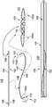
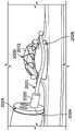
图1示出了本说明书中的实施例的利用由第一构件和第二构件实现的锚固的切除装置;Figure 1 shows a resection device of an embodiment of the present specification utilizing anchorage achieved by a first member and a second member;
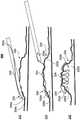
图2A示出了本说明书中的一个实施例的使用如图1所述的具有第一构件和第二构件或回缩钩的切除装置的方法的多个步骤;FIG. 2A illustrates various steps of a method of using a cutting device having a first member and a second member or retraction hook as described in FIG. 1 according to one embodiment of the present specification;
图2B是本说明书中的一个实施例中的图2A的方法的多个步骤的流程图;FIG. 2B is a flowchart of steps of the method of FIG. 2A in one embodiment of the present specification;
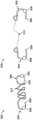
图3示出了在本说明书中的实施例中使用的切除装置设计的实施例;Figure 3 shows an embodiment of a cutting device design used in the embodiments in this specification;
图4示出了在本说明书中的实施例中采用的输送导管的实施例;Figure 4 shows an embodiment of a delivery catheter employed in the embodiments in this specification;
图5示出了在本说明书中的实施例中使用的装载到输送装置的内导管上的切除装置;Figure 5 shows the cutting device loaded onto the inner catheter of the delivery device used in the embodiments of this specification;
图6示出了本说明书中的实施例的横跨病灶施加的两个切除装置;Figure 6 shows two resection devices applied across a lesion of embodiments of the present specification;
图7示出了在本说明书中的实施例中采用的多种切除装置;Figure 7 illustrates various cutting devices employed in the embodiments in this specification;
图8示出了在本说明书中的实施例中采用的示例性切除装置的尺寸;Figure 8 shows the dimensions of an exemplary resection device employed in embodiments in this specification;
图9示出了在本说明书中的其它实施例中采用的示例性切除装置的尺寸;Figure 9 shows the dimensions of an exemplary resection device employed in other embodiments in this specification;
图10A示出了在本说明书中的实施例中采用的三构件或钩式切除装置;Figure 10A shows a three-member or hook resection device employed in embodiments in this specification;
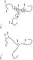
图10B示出了在本说明书中的其它实施例中采用的三构件或钩式切除装置;Figure 10B shows a three-member or hook resection device employed in other embodiments in this specification;
图10C是本说明书的一些实施例的部署三构件或钩式切除装置的方法的多个示例性步骤的流程图;10C is a flowchart of various exemplary steps of a method of deploying a three-member or hook resection device of some embodiments of the present specification;
图11示出了在本说明书中的实施例中采用的多种穿刺构件或钩的实施例;Figure 11 illustrates various piercing member or hook embodiments employed in the embodiments in this specification;
图12示出了在本说明书中的实施例中采用的多种非穿刺构件或钩的实施例;Figure 12 illustrates various non-piercing member or hook embodiments employed in the embodiments in this specification;
图13示出了在本说明书中的实施例中采用的具有绝缘覆层的构件或钩的一个实施例;Figure 13 shows one embodiment of a member or hook with an insulating coating employed in the embodiments in this specification;
图14示出了用于接合至少两个构件或钩并为聚集病灶提供弹性的中央部分的一个实施例;Figure 14 illustrates one embodiment of a central portion for engaging at least two members or hooks and providing elasticity to a clustered lesion;
图15示出了在本说明书中的实施例中在至少两个构件或钩与至少一个中央部分或线圈之间的连接;Figure 15 shows the connection between at least two members or hooks and at least one central portion or loop in an embodiment in this specification;
图16示出了在本说明书中的实施例中使用的切除装置;Figure 16 shows the cutting device used in the embodiments in this specification;
图17示出了在本说明书中的实施例中可用于连接构件或钩和中央部分或线圈的连接器的多种实施例;Figure 17 illustrates various embodiments of connectors that may be used to connect a member or hook and a central portion or coil in embodiments in this specification;
图18示出了在本说明书中的实施例中采用的电外科装置的一种示例性配置;Figure 18 shows an exemplary configuration of an electrosurgical device employed in the embodiments in this specification;
图19A示出了在本说明书中的实施例中采用的电外科刀的一种示例性配置;Figure 19A shows an exemplary configuration of an electrosurgical knife employed in embodiments in this specification;
图19B是本说明书中的一些实施例的包括组装好的第一电极和第二电极的加热室的纵向横截面图;19B is a longitudinal cross-sectional view of a heating chamber including assembled first and second electrodes of some embodiments of the present specification;
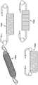
图20A示出了在本说明书中的实施例中在切除手术中使用的勒除器装置;Figure 20A shows a snare device used in a resection procedure in embodiments in this specification;
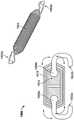
图20B是配置成与本说明书中的切除装置结合工作的磁性勒除器装置的一个实施例;Figure 20B is one embodiment of a magnetic snare device configured to work in conjunction with the resection device of the present specification;
图20C示出了本说明书中的实施例的与切除装置结合使用磁性勒除器装置来切除病灶;Figure 20C illustrates the use of a magnetic snare device in conjunction with a resection device to resect a lesion according to embodiments of the present specification;
图20D是本说明书中的一些实施例的在切除手术中将图20A的勒除器装置与切除装置结合使用的方法的多个示例性步骤的流程图;Figure 20D is a flowchart of several exemplary steps of a method of using the snare device of Figure 20A in conjunction with a resection device in a resection procedure, according to some embodiments of the present specification;
图20E是本说明书中的一些实施例的在切除手术中将图20B的磁性勒除器装置与三构件或钩式切除装置结合使用的方法的多个示例性步骤的流程图;20E is a flowchart of several exemplary steps of a method of using the magnetic snare device of FIG. 20B in conjunction with a three-member or hook resection device in a resection procedure, according to some embodiments of the present specification;
图20F示出了与本说明书中的切除装置结合使用的可变尺寸的勒除器装置;Figure 20F shows a variable size snare device used in conjunction with the resection device of the present specification;
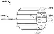
图21示出了本说明书中的实施例中的使用切除装置进行的粘膜下切除手术;Figure 21 shows a submucosal resection using a resection device in the embodiments of the present specification;
图22是与本说明书中的实施例一起使用的定向接地帽的示意图;22 is a schematic diagram of a directional ground cap for use with embodiments in this specification;
图23示出了与本说明书中的实施例一起使用的图22所示的定向接地帽的功能;Figure 23 illustrates the functionality of the directional ground cap shown in Figure 22 for use with embodiments in this specification;
图24示出了与本说明书中的实施例一起使用的双极帽切除器的一个实施例;和FIG. 24 illustrates one embodiment of a bipolar cap resector for use with embodiments in this specification; and
图25示出了与本说明书中的实施例一起使用的双极帽切除器的另一个实施例。Figure 25 shows another embodiment of a bipolar cap cutter for use with embodiments in this specification.
具体实施方式Detailed ways
本说明书涉及一种用于进行病灶的内窥镜下切除(ER)或内窥镜全层切除(EFTR)的装置和方法。本说明书公开了一种利用由第一构件和第二构件实现的锚固的切除装置。所述第一构件和第二构件由中央部分接合,该中央部分配置成在部署后卷绕,从而将已经抓住体内病灶的组织部分的第一构件和第二构件拉在一起,由此收缩和压缩病灶,并减小病灶的至少一个尺寸。这种聚集或收紧病灶的功能使得病灶更容易使用勒除器或电灼装置移除。The present specification relates to a device and method for performing endoscopic resection (ER) or endoscopic full-thickness resection (EFTR) of a lesion. The present specification discloses a resection device utilizing anchorage achieved by a first member and a second member. The first and second members are joined by a central portion configured to coil upon deployment, thereby drawing together the first and second members that have grasped the tissue portion of the lesion in the body, thereby contracting and compress the lesion and reduce at least one dimension of the lesion. This ability to gather or tighten the lesion makes it easier to remove using a snare or electrocautery device.
本说明书涉及多个实施例。以下公开内容的目的是使本领域普通技术人员能够实践本发明。在本说明中使用的语言应按本文中所用的术语的含义理解,不应理解为排除任何特定的实施例或用于限制所附的权利要求。在此限定的总体原则也适用于其它实施例和应用,而不会脱离本发明的精神和范围。而且,所用的术语和用语仅用于说明示例性实施例的目的,不应理解为限制性的。因此,本发明应按涵盖与所公开的原理和特性相符的众多可替代方案、修改方案和等效方案的最宽范围来理解。为了清楚起见,未详细说明与本发明相关的技术领域中所公知的技术材料的细节,以免使本发明变得难以理解。This specification refers to various embodiments. The purpose of the following disclosure is to enable those of ordinary skill in the art to practice the invention. Language used in this specification is to be taken in accordance with the meaning of the terms used herein and should not be construed to exclude any particular embodiment or to limit the claims that follow. The general principles defined herein also apply to other embodiments and applications without departing from the spirit and scope of the present invention. Also, the terminology and phraseology used is for the purpose of describing the exemplary embodiment only and should not be regarded as limiting. Therefore, the present invention is to be accorded the widest scope to encompass numerous alternatives, modifications, and equivalents consistent with the principles and characteristics disclosed. For the purpose of clarity, details of technical material that is known in the technical fields related to the invention have not been described in detail so as not to obscure the present invention.
在本申请的说明书和权利要求中,术语“包括”、“包含”和“具有”之中的每一个以及其各种形式不一定局限于该术语所关联的列表中的成员。在此应说明的是,除非明确指出,否则结合特定实施例说明的任何特征或部件可以与任何其它实施例一起使用和实施。In the specification and claims of this application, each of the terms "comprising," "comprising," and "having," and their various forms, are not necessarily limited to the members of the list to which the term is associated. It should be noted here that any feature or component described in connection with a particular embodiment can be used and implemented with any other embodiment unless expressly stated otherwise.
图1示出了本说明书中的实施例的利用由第一构件102a和第二构件102b实现的锚固的切除装置100。在实施例中,第一构件102a和第二构件102b包括回缩钩。在实施例中,可以使用导管结构105部署第一构件和第二构件或回缩钩102a、102b。在实施例中,导管105包括内导管106和外导管107,所述内导管106配置成保持和部署切除装置100,所述外导管107同轴地包覆内导管106,并用于将内导管106和切除装置100输送至目标组织。外导管107包括防止损伤的远端和外表面,并且在被置于组织的目标附近时缩回,以露出内导管106和切除装置100。FIG. 1 illustrates a
在实施例中,第一构件和第二构件或每个回缩钩102a、102b包括用于刺穿身体组织的穿刺末端103。在实施例中,第一构件或回缩钩102a被置于装置100的中央部分104(例如线圈)的第一端或远端112上,而第二构件或回缩钩112b位于中央部分的第二端或近端113上。所述构件或回缩钩102a、102b配置成在中央部分104卷绕时用作锚钉,从而将组织的两个被刺穿端拉在一起。在实施例中,所述第一构件和第二构件或回缩钩102a、102b还包括位于穿刺末端103与中央部分104之间的止挡件108,以提供穿刺组织的止点。可选地,在每个钩102a、102b上布置有至少一个止挡件108,其中所述止挡件108的至少一个尺寸大于钩线109的直径。在一些实施例中,止挡件108的直径在0.5至5毫米的范围内。在一些实施例中,从邻近中央部分104的止挡件108一端到与所述止挡件端相对的穿刺末端103的一端的回缩钩102a、102b的长度l在1至10毫米的范围内。在一些实施例中,止挡件108由铁磁性或磁性元件组成。所述磁性元件可以是稀土磁体。在实施例中,止挡件108覆有绝缘层,例如陶瓷层或PTFE。切除装置100被装载到内导管106上,该内导管106具有用于将两个回缩钩102a、102b部署和定位到器官内的一个或更多个目标区域中的机构。In an embodiment, the or each
第一视图115示出了处于第一完全伸展的直线形态的切除装置100。在第二构件或回缩钩102b抓住或接合身体组织的第二部分(例如病灶)并且中央部分104完全卷绕之后,切除装置100从视图115中所示的第一完全伸展的直线形态转变为视图117中所示的第二完全卷绕形态。视图116示出了处于部分地卷绕或弯曲形状的变形期间的切除装置100,此时第一构件或回缩钩102a抓住或接合身体组织或病灶的第一部分,并且被线圈从内导管部署。在实施例中,当切除装置100从视图115中所示的第一完全伸展的直线形态过渡到视图117中所示的第二完全卷绕形态时,其长度减小10%至90%。视图118示出了装载在导管结构105的内导管106上的切除装置100。在实施例中,切除装置100(尤其是中央部分104)具有形状记忆特性,以便于形态的改变。在一些实施例中,切除装置100或仅中央部分104由镍钛合金构成。在一些实施例中,切除装置100或仅中央部分104由在暴露于特定温度(例如人体的正常温度)时改变形状的温敏材料构成。在一些实施例中,中央部分104由弹性材料构成,例如硅树脂、乳胶橡胶或无乳胶腈。The
图2A示出了使用如图1所述的具有第一构件和第二构件或回缩钩的切除装置的方法200的多个步骤,而图2B是本说明书中的一个实施例的方法200的多个步骤的流程图。现在请参考图2A和2B,在步骤222中,切除装置200(包括图1的第一构件和第二构件或回缩钩102a、102b和中央部分104)从部署导管205的远端伸展,并且第一构件或回缩钩202a在第一位置刺入或抓住病灶220的第一部分或边缘220a。在步骤224中,缩回导管205,使得切除装置200被拉过病灶220,并且第二构件或回缩钩202b在第二位置刺入或抓住病灶220的第二部分或边缘220b。在实施例中,所述第二位置相对于所述第一位置在病灶220的相对边缘上。在步骤226中,移除导管205,并释放横跨病灶220的切除装置200,以允许中央部分或线圈204缩回并将第一构件或回缩钩202a和第二构件或回缩钩202b拉在一起,使得病灶220的两个边缘220a、220b更靠近在一起,并且病灶220的边缘220a、220b被拉向病灶220的中心,从而减小病灶220的至少一个尺寸。FIG. 2A shows various steps of a
图3示出了在本说明书中的实施例中使用的切除装置设计的实施例。在实施例中,切除装置302包括位于切除装置302的第一端的第一构件或回缩钩304以及位于切除装置302的与第一端相对的第二端的第二构件或回缩钩306。第一构件或回缩钩304包括第一穿刺末端307和第一止挡件308,第二构件或回缩钩306包括第二穿刺末端309和第二止挡件310。这两个构件或钩304、306由中央部分312连接,该中央部分312包括由具有形状记忆的材料(例如镍钛合金)制成的线圈。在另一个实施例中,切除装置303包括位于切除装置302的第一端的第一构件或回缩钩304和位于切除装置302的与第一端相对的第二端的第二构件或回缩钩306。第一构件或回缩钩304包括第一穿刺末端307和第一止挡件308,第二构件或回缩钩306包括第二穿刺末端309和第二止挡件310。这两个构件或钩304、306被中央部分313连接,该中央部分313包括由硅树脂、乳胶橡胶或无乳胶腈制成的弹性连接器。在实施例中,止挡件308由陶瓷、PTFE、硅树脂、玻璃、SST、镍钛合金、或铁磁性或磁性材料(例如稀土磁体)制成。在实施例中,止挡件的直径范围为0.5至5毫米。Figure 3 shows an example of a cutting device design used in the examples in this specification. In an embodiment, the
图4示出了在本说明书中的实施例中采用的输送导管的实施例。在实施例中,输送导管400包括内导管402和外导管404。在实施例中,内导管402的远侧末端412包括至少一个第一凹槽408,该第一凹槽408配置成与切除装置420的第一构件或回缩钩422接合,以固定切除装置420的第一端。内导管402还包括从所述至少一个第一凹槽408向近侧延伸的狭缝414和至少一个第二凹槽409,所述狭缝414配置成可滑动地接收切除装置420的第一构件或回缩钩422、第二构件或第二回缩钩424和/或中央部分421的一部分,所述第二凹槽409位于狭缝414的端部,配置成与切除装置420的第二构件或回缩钩424接合,以固定切除装置420的与第一端相对的第二端。在内导管402中示出的一个实施例中,所述至少一个第一凹槽408位于内导管402的远侧末端412的端部。在内导管428中示出的另一个实施例中,所述至少一个第一凹槽418位于内导管428的远侧末端412的一侧。Figure 4 shows an embodiment of a delivery catheter employed in the embodiments in this specification. In an embodiment,
图5示出了装载在导管输送装置的内导管502的另一个实施例上的切除装置500。在一个实施例中,切除装置500被预装到内导管502上。在一个实施例中,内导管502的圆形轮廓容纳切除装置500的止挡件508,而中央部分506环绕内导管502。沿着内导管502的长度设有狭缝504,以可滑动地接收和容纳中央部分506的至少一部分。狭缝504允许中央部分506沿着内导管502滑动,使得它可以被从外导管推出(如图4中的附图标记404所示)。狭缝504在一端具有钩状结构510,以防止中央部分506的意外滑动。狭缝504的钩状结构510还允许钩住和拉动切除装置的中央部分506的端部上的第一构件和第二构件或回缩钩512a、512b。Figure 5 shows a
图6示出了使用两个切除装置610a、610b(每个都包括图1的第一构件和第二构件或回缩钩102a、102b以及中央部分104)的切除,这两个切除装置以如在本说明书的实施例中使用以及参照图2所述的方式在部署前形态620和部署后形态625中横跨病灶612施加。在病灶612被“聚集”或其尺寸减小后,使用勒除器630或针刀或任何其它适当的切除技术切除病灶612。此外,在实施例中,可以使用盐水或另一种提升剂的粘膜下注射来提起病灶612。在内窥镜下解剖的情况中,病灶612的切除边缘被拉向病灶612的中心,从而提起切除边缘以使其从切除点向病灶612的中心移动,由此露出解剖平面,以便于接近以进行继续解剖。FIG. 6 shows resection using two
图7示出了在本说明书中的实施例中采用的切除装置的第一、第二、第三和第四形态700a、700b、700c、700d。FIG. 7 illustrates first, second, third and
图8示出了在本说明书中的实施例中采用的切除装置800的示例性尺寸。在实施例中,切除装置800具有在5到35毫米范围内的总长度,而在部署后的完全卷绕形态中,中央部分804的长度在5到25毫米的范围内。在实施例中,当处于部署后的完全卷绕形态时,中央部分804具有2至10毫米的宽度。在实施例中,当切除装置800处于部署后的完全卷绕形态时,线圈805的单圈的长度在0.2至1.5毫米的范围内。在实施例中,每个止挡件808具有在0.5至10毫米的范围内的直径。在实施例中,每个构件或回缩钩802(包括止挡件和穿刺末端803)具有从中央部分804延伸测量的3到20毫米的长度。Figure 8 shows exemplary dimensions of a
图9示出了在本说明书中的其它实施例中采用的切除装置900、920的示例性尺寸。在实施例中,当处于部署后的完全卷绕形态时,切除装置900具有3至20毫米的范围内的总宽度De,并且配置成配装在具有3至25毫米的范围内的高度H的空间内。切除装置900具有从第一构件或回缩钩902a的内表面到第二构件或回缩钩902b的内表面的长度L0,长度L0的范围为5至35毫米。在实施例中,当切除装置905处于部署后的完全卷绕形态时,线圈900的单圈的长度d在0.2至1.5毫米的范围内。在实施例中,第一构件或回缩钩902a位于偏离第二平面的第一平面内,其中第二构件或回缩钩902b处于90度的位置。在实施例中,切除装置920在处于部署后的完全卷绕形态时具有5至35毫米的总长度L。当切除装置处于部署后的完全卷绕形态时,第一构件或回缩钩922a和第二构件或回缩钩922b分别具有从中央部分924的一端延伸至每个钩922a、922b的弯曲端的高度H,该高度H的范围从1.5至15毫米。当切除装置920处于部署后的完全卷绕形态时,在中央部分的每个端部与每个钩的每个穿刺末端923之间存在间隙925,并且该间隙925具有在1到10毫米范围内的长度G。在切除装置920处于部署后的完全卷绕形态时,中央部分924形成具有在3至35毫米范围内的外径OD的线圈。Figure 9 shows exemplary dimensions of
如前文中参照图1所论述的,在实施例中,本说明书中的切除装置包括具有用于抓住或刺穿器官的穿透或锋利末端的构件,或者,在其它实施例中,具有包括钝头末端的构件,以与器官表面或器官表面中的缺陷接合。在所有实施例中,穿刺末端或钝头末端将构件锚固至器官表面。在一些实施例中,可以使用单独的装置或电灼技术将钝头末端置于在器官的内层中产生的缺陷内。所述切除装置在每个钩上具有止挡机构或止挡件,当构件或钩被拉向彼此时,该止动机构或止挡件防止构件或钩埋入器官中过深。所述牵拉动作产生收紧力,而不是将钩子埋得很深,从而避免了器官壁的穿孔。As discussed above with reference to FIG. 1, in embodiments, a resection device in this specification includes a member having a penetrating or sharpened tip for grasping or piercing an organ, or, in other embodiments, has a member including A member with a blunt tip to engage with an organ surface or a defect in an organ surface. In all embodiments, the piercing tip or blunt tip anchors the member to the organ surface. In some embodiments, a separate device or electrocautery technique can be used to place the blunt tip within the defect created in the lining of the organ. The resection device has a stop mechanism or stop on each hook that prevents the members or hooks from burying too deep into the organ when the members or hooks are pulled towards each other. The pulling action creates a tightening force rather than burying the hook deeply, thereby avoiding perforation of the organ wall.
图10A示出了在本说明书中的实施例中采用的三构件或钩式切除装置1000、1020。锚钉1000包括三个构件或回缩钩1002,每个构件或回缩钩包括至少一个止挡件1008和用于在第一位置、第二位置和第三位置刺穿目标组织或病灶的部分的穿刺末端1003。在实施例中,所述第一位置、所述第二位置和所述第三位置在病灶的边缘周围等距地间隔开。每个构件或回缩钩1002通过中央部分1004连接至中央连接毂1006。在实施例中,每个中央部分1004包括弹性连接器。请参考图10B和三构件或钩式切除装置1030、1040,在其它实施例中不包括中央连接毂,并且每个中央部分1004的与每个构件或钩1002相对的端部附接在一起,例如通过缝合、捆扎、胶粘或焊接附接在一起。请再次参考图10A,切除装置1020包括三个构件或回缩钩1002,每个构件或回缩钩包括至少一个止挡件1008和穿刺末端1003。每个构件或回缩钩1002通过中央部分1005连接至中央连接毂1007。在实施例中,每个中央部分1005包括镍钛合金连接器。在实施例中,中央连接毂1006、1007包括球窝接头,以允许切除装置1000的弹性连接器的中央部分1004和钩1002或者切除装置1020的镍钛合金连接器的中央部分1005和钩1002相对于中央连接毂1006、1007进行关节运动。钩1002配置成与用于根据需要放置和重新定位钩1002的输送导管的内部构件可逆地接合。Figure 10A shows a three-member or
图10C是本说明书中的一些实施例的部署三构件或钩式切除装置(例如装置1000、1020、1030或1040)的方法的多个示例性步骤的流程图。在步骤1050中,三构件或钩式切除装置从部署导管的远端伸出,并且第一构件或回缩钩抓住或刺入病灶或目标组织的第一边缘或部分。在步骤1052中,部署导管向第一方向以及向近侧沿侧向移动,并且第二构件或回缩钩抓住或刺入病灶或目标组织的第二边缘或部分。在步骤1054中,部署导管向与第一方向相反的第二方向并向近侧沿侧向移动,并且第三构件或回缩钩刺入病灶或目标组织的第三边缘或部分。10C is a flow diagram of various exemplary steps of a method of deploying a three-member or hook resection device (eg,
在步骤1056中,移除部署导管,并释放横跨病灶或目标组织的切除装置,以允许第一中央部分、第二中央部分和第三中央部分(每个中央部分将第一、第二和第三构件或回缩钩连接至中央连接毂或附接在一起)回缩并将第一、第二和第三构件或回缩钩拉到一起,使得病灶或目标组织的第一、第二和第三边缘或部分更靠近在一起,并且病灶或目标组织的边缘或部分被大致地向病灶或目标组织的中心拉动。In
图11示出了本说明书中的一些实施例的切除装置的构件或回缩钩1102a、1102b、1102c、1102d的穿透或穿刺末端1104a、1104b、1104c、1104d的多种实施方案。每个穿刺末端包括至少一个沿第一方向延伸的第一尖锐部分和至少一个沿相反方向延伸的第二尖锐部分,以产生配置成刺入身体组织中的倒钩1106a、1106b、1106c、1106d。每个回缩钩1102a、1102b、1102c、1102d还包括至少一个止挡件1108a、1108b、1108c、1108d。11 illustrates various embodiments of the penetrating or piercing
图12示出了在本说明书中的实施例中采用的构件或回缩钩1202a、1202b、1202c、1202d、1202e、1202f、1202g、1202h的非穿透或非穿刺末端1204a、1204b、1204c、1204d、1204e、1204f、1204g、1204h的多种实施方案。非穿透或非穿刺末端1204a、1204b、1204c、1204d、1204e、1204f、1204g、1204h包括配置成通过由不同工具(例如电手术刀或烧灼头)产生的独立切口或缺损部与器官接合的钝端1209a、1209b、1209c、1209d、1209e、1209f、1209g、1209h。非穿透或非穿刺末端1204a、1204b、1204c、1204d、1204e、1204f、1204g、1204h配置成将钩保持在组织的内层的缺损部或壁中的适当位置,并且不穿透组织。请参考图12,构件或回缩钩1202e、1202f、1202g、1202h分别包括至少一个止挡件1208。在一些实施例中,止挡件材料或元件用于产生钝端1209a、1209b、1209c、1209d、1209e、1209f、1209g、1209h。Figure 12 shows the non-penetrating or
图13示出了在本说明书中的实施例中采用的带有绝缘覆层1302的切除装置的构件或回缩钩1300的一个实施例。此实施例防止来自与切除装置接触的电外科器械的电力传递到组织中并由此导致在切除装置中及其周围发生意外组织损伤。FIG. 13 illustrates one embodiment of a member or
图14示出了用于接合切除装置的至少两个构件或回缩钩并为聚集病灶提供弹性的中央部分1400的一个实施例的前后向横截面图。在实施例中,中央部分1400包括芯件1402,该芯件1402优选由弹性材料制成,例如硅树脂、特氟隆、橡胶或乳胶。金属或合金线圈1404包围芯件1402。最后,在弹性芯件/线圈1402、1404周围设有弹性套管1406。优选地,套管1406由绝缘材料制成,以将线圈1400与电外科器械绝缘。Figure 14 illustrates a front-to-back cross-sectional view of one embodiment of a
图15示出了本说明书中的一些实施例的切除装置1500的两个构件或回缩钩1502a、1502b与中央部分1504之间的连接的侧向横截面图。在实施例中,中央部分1504包括芯件1512,该芯件1512优选由弹性材料制成。金属或合金线圈1514包围芯件1512。最后,在弹性芯件/线圈1512、1514周围设有弹性套管1516。优选地,套管1516由绝缘材料制成。在实施例中,在中央部分1504的每一端设有球窝接头1508a、1508b,以附接构件或回缩钩1502a、1502b,并允许构件或回缩钩1502a、1502b相对于中央部分1504进行关节运动。此外,球窝接头1508a、1508b由绝缘材料构成或被绝缘材料覆盖,以将构件或钩1502a、1502b与中央部分1504电绝缘。15 shows a side cross-sectional view of the connection between the two members or
图16示出了本说明书中的一些实施例的切除装置1600的侧向横截面图。切除装置1600包括中央部分1604,该中央部分1604包括覆有弹性材料1616的线圈1614。在一个实施例中,球窝接头1608a、1608b允许构件或回缩钩1602a、1602b相对于中央部分1604向一个或更多个方向并在10度至90度的范围内进行关节运动。有利的是,钩1602a、1602b的长轴可以相对于中央部分1604的长轴相对自由地旋转,这有助于在病灶或器官的不规则表面中的不同平面或方向上锚定。Figure 16 shows a side cross-sectional view of a
图17示出了本说明书中的实施例的连接器1708的多种实施例,该连接器1708可用于将构件或钩1702连接至切除装置的中央部分或线圈1704。在多种实施例中,连接器1708包括但不限于杆和环(肘节)1708a、钩1708b、盒形钩扣1708c、龙虾爪1708c、磁性1708e、弹簧圈1708f、螺钉1708g、滑动锁1708h、铰接夹1708i、扭转夹1708j、插塞1708k、球窝17081、滑动扣1708m、带扣1708n、按钮扣1708o、弹簧锁(表扣)1708p、表扣转换器1708q、表扣组合1708r、拉环锁1708s、纽扣螺柱铆钉1708t、锚钩环1708u、弹出式1708v、锁1708w和管锁1708x型连接器。Figure 17 shows various embodiments of a
图18示出了包括与本说明书中的各种实施例中的切除装置1800一起使用的电灼器(ESU)1820的系统1801的示例性配置。ESU 1820为单极装置1822提供内部回路1821和通向皮肤1828上的接地垫1826的电路径1824。在其它实施例中,ESU 1820提供双极系统,其中电路径从与目标组织的一个区域接触的一个电极点到与目标组织的另一个区域接触的另一个电极点。首先在目标病灶1812处部署图18中的具有三个分别包括止挡件1808和穿刺末端1803的构件或回缩钩1802的切除装置1800。切除装置1800还包括中央连接毂1807,并且每个构件或回缩钩1802通过包括镍钛合金连接器的中央部分1805连接至中央连接毂1807,这与图10所示的切除装置1020类似。回缩钩1802将病灶1812的边缘拉在一起,并拉向病灶1812的中心。然后使用勒除器或电外科刀1825切断升起的病灶1812。ESU 1820提供电灼,以帮助去除病灶1812。FIG. 18 shows an exemplary configuration of a
图19A示出了与本说明书中的实施例中的切除装置一起使用的电外科刀或针刀1900的示例性配置。在实施例中,在外导管1904上设有电连接器1902。在实施例中,外导管的外径范围为2至4毫米,长度范围为110至450厘米。电外科刀或针刀1900还包括针/刀1906,该针/刀1906同轴地部署在外导管1904内,并且可以延伸到超出外导管的远侧末端1毫米至10毫米的距离处。在实施例中,针/刀1906具有在28G到16G范围内的规格。可选地,外导管的远侧末端和/或针/刀1906的近侧部分被绝缘,以防止伤害附近的非目标组织。在实施例中,设有电连接器1902以将针/刀1906连接至如图18所示的电灼器(ESU)1800,以施加电灼。设有输入端口1910用于输送流体,例如盐水。设有另外的侧端口1912用于注入另外的流体,以通过外导管1904的远端处的第二输出端口1929输送流体,以冷却外导管1904或组织区域。在外导管1904内直列设置加热室1920,以将通过输入端口1910输送的流体加热到50至100摄氏度的范围内。加热室1920可以沿着外导管1904的长度部署在从导管手柄到外导管1904的末端的范围内的任何位置。在一些实施例中,加热室1920包括多个电极,这些电极配置成接收电流并加热流过加热室的流体,如下文所述。在一些实施例中,加热室1920配置成加热(从输入端口1910提供的)流体,以通过外导管1904的远端处的第一输出端口1927输送到目标组织中或目标组织附近,以辅助切除过程。加热室1920配置成加热流体/盐水,同时确保流体/盐水不会蒸发。在实施例中,外导管1904包括至少一个用于输送通过输入端口1910提供并由加热室1920加热的第一流体(盐水)的第一内腔、至少一个用于输送由侧端口提供的第二流体以进行冷却的第二内腔1924、以及用于向针/刀1906输送电流的导线1926。FIG. 19A shows an exemplary configuration of an electrosurgical knife or
所述至少一个第一内腔1920与输入端口1910和位于外导管1904的远侧末端处的第一输出端口1927流体连通。所述至少一个第二内腔1924与侧端口1912和位于外导管1904的远侧末端处的第二输出端口1929流体连通。导线1926与电连接器1902和针/刀1906电连通。电连接器1902连接至ESU,以通过针/刀1906提供电烙。The at least one
图19B是本说明书中的一些实施例的包括组装好的第一电极136和第二电极138的加热室1920的纵向横截面图125。配置为第一电极阵列136和第二电极阵列138的多个电极分别包括金属环142、144,多个电极翅片或元件136’、138’从金属环142、144沿着加热室1920的纵向轴线150径向和纵向延伸。换句话说,电极翅片136’、138’中的每一个具有沿着加热室1920的半径的第一尺寸和沿着加热室1920的纵向轴线150的第二尺寸。电极翅片或元件136’、138’在它们之间限定多个分段空间140,盐水/水流过这些空间并被加热。电流被从控制器引入外导管,通过第一内腔,并到达电极136、138,这使得翅片或元件136’、138’产生热量,该热量然后被传递至盐水,以加热盐水。第一尺寸和第二尺寸使得电极136、138具有用于加热在空间140中流动的盐水/水的增大表面积。根据一个实施例,第一电极136具有第一极性,第二电极138具有与所述第一极性相反的第二极性。在一个实施例中,第一极性是负的(阴极),而第二极性是正的(阳极)。电极136、138(包括环142、144和翅片或元件136’、138’)都是柔性的,以允许导管的远侧部分或末端弯曲,从而在切除手术期间更好地定位外导管。19B is a longitudinal cross-sectional view 125 of a
如图19B所示,在组装加热室1920时,电极翅片或元件136’、138’相互交叉或互锁(类似于两只紧握的手的手指),使得阴极元件和阳极元件交替排列,而空间140将每个阴极元件和阳极元件分开。在多种实施例中,每个空间140具有从阴极元件到阳极元件的0.01毫米至2毫米的距离。在一些实施例中,第一电极阵列136具有1至50个电极翅片136’,优选数量为4个电极翅片136’,而第二电极阵列138具有1至50个电极翅片138’,优选数量为4个电极翅片138’。在多种实施例中,加热室130具有1至5毫米范围内的宽度w和5至50毫米范围内的长度l。在一些实施例中,加热室1920包括至少一个传感器137。在多种实施例中,所述至少一个传感器137包括阻抗、温度、压力或流量传感器,压力传感器不是太优选的。在一个实施例中,可以感测电极阵列136、138的电阻抗。在其它实施例中,可以感测流体的温度、电极阵列的温度、流体的流速、压力或类似参数。As shown in Figure 19B, when the
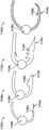
图20A示出了在本说明书中的实施例中的切除手术中与切除装置一起使用的勒除器装置。勒除器装置2020穿过内窥镜2024的通道2023。部署切除装置2000以“聚集”或“收紧”病灶2012。在病灶2012被“聚集”后,可以使用生理盐水或本领域普通技术人员已知的另一种提升剂的粘膜下注射2028来进一步提起病灶2012。随后,使用勒除器装置2020切除病灶2012。向用于通过电烙去除病灶2012的勒除器装置的环2021提供电流。在一些实施例中,所使用的勒除器装置类似于在第US 2017-0007279 A1号美国专利申请公开中公开的勒除器装置,该专利申请的内容通过引用整体并入本文。Figure 20A shows a snare device used with a resection device in a resection procedure in the embodiments of this specification. The
在一些实施例中,勒除器装置还包括磁性或铁磁性元件,以与回缩钩上的一个或更多个止挡件连接,从而将勒除器装置的勒除器环的一部分固定至切除装置的回缩钩。在多种实施例中,所述磁性或铁磁性元件被固定到勒除器切除装置的勒除器环的金属线上,或者沿着勒除器环的金属线自由移动。在多种实施例中,这些磁性或铁磁性元件的极性被设置成使得它们排斥相邻的磁性/铁磁性元件,从而在勒除器上时不会聚集在一起,由此防止阻断勒除器装置的打开和闭合功能。在多种实施例中,所述磁性/铁磁性元件被设计成与回缩钩的磁性或铁磁性元件接合。In some embodiments, the snare device further includes a magnetic or ferromagnetic element to connect with one or more stops on the retraction hook to secure a portion of the snare loop of the snare device to the Retraction hook of the cutting device. In various embodiments, the magnetic or ferromagnetic element is affixed to the wire of the snare ring of the snare removal device, or is free to move along the wire of the snare ring. In various embodiments, the polarities of the magnetic or ferromagnetic elements are set such that they repel adjacent magnetic/ferromagnetic elements so as not to clump together when on the snare, thereby preventing blocking of the snare The opening and closing function of the eliminator device. In various embodiments, the magnetic/ferromagnetic element is designed to engage with a magnetic or ferromagnetic element of the retraction hook.
图20B是配置成与本说明书中的切除装置结合工作的磁性勒除器装置2030的一个实施例。勒除器环2031由非铁磁性材料(例如尼龙)或镍钛合金构成。至少一个第一磁体2032同轴地置于勒除器环2031的金属线上或附接到其上,并且相对于勒除器环2031的长度相对地固定。至少一个第二磁体2033穿在勒除器环2031上,并且相对于勒除器环2031的长度可相对移动。磁性勒除器装置2030还包括至少一个固定的非铁磁性推动元件2034,该推动元件2034同轴地置于勒除器环2031上或附接至勒除器环2031,并且置于每个移动磁体2033的近侧,该推动元件2034配置成将移动磁体2033从磁性勒除器装置2030的主体2035推出。在实施例中,推动元件2034是固定至勒除器环2031的圆珠,该圆珠配置成将移动磁体2033从主体2035推出,并防止移动磁体2033沿着勒除器环2031向近侧移动。在一些实施例中,至少一个第三磁体2037附接至勒除器护套2036。在多种实施例中,所述至少一个第三磁体固定至勒除器护套2036或者可从勒除器护套2036分离。Figure 20B is one embodiment of a
移动磁体2033的极性布置成使得勒除器环2031上的两个移动磁体2033相互排斥。磁性勒除器装置2030包括用于连接至ESU的电外科连接器2038。磁性勒除器装置2030配置成将来自电外科连接器2038的电外科电流通过穿过磁性勒除器装置2030延伸的金属线2040传递至勒除器环2031,或者通过勒除器护套2036的内腔2039传递替代能量。磁性勒除器装置2030还包括用于驱动装置2030的手柄2041。在实施例中,手柄2041包括第一指孔部分2042,该第一指孔部分2042围绕第二指孔部分2043同轴地布置,并可在第二指孔部分2043的狭槽2044内纵向滑动。在实施例中,向近侧方向滑动第一指孔部分2042同时向远侧方向移动第二指孔部分2043会闭合勒除器环2031。The polarity of the moving
图20C示出了本说明书中的实施例的与切除装置2050结合使用磁性勒除器装置2070来切除病灶。勒除器装置2070穿过内窥镜2084的通道2083。部署切除装置2050以“聚集”或“收紧”病灶2092。勒除器环2071上的最远侧固定磁体2072与切除装置2050的第一构件或回缩钩2052a的第一铁磁性止挡件2058a接合。该构件或回缩钩2052a通过切除装置2050的中央部分2054或线圈连接至中央连接毂2057。Figure 20C illustrates the use of a
在勒除器环2071被打开时,两个非固定磁体2073a、2073b与切除装置2050的第二和第三构件或回缩钩2052b、2052c上的一个或更多个铁磁性止挡件2058b、2058c接合。可选的推动元件2074用于将磁体2073a、2073b从勒除器主体2075推出,并将这些磁体2073a、2073b保持在勒除器环2071的远侧80%内的位置。在闭合勒除器环2071的同时,推动元件2074缩回到勒除器主体2075中,并且不会显著干扰勒除器装置2070的功能。在施加电烙或替代切除能量之前和期间,勒除器环2071的金属线相对于移动磁体2073a、2073b滑动,从而进一步收紧病灶2092,同时保持所述金属线相对于止挡件和病灶的位置。在施加电烙或替代切除能量之前和期间,耦接至远侧铁磁性止动器2058a的固定磁体2072将病灶2092的远侧边缘拉向勒除器主体2075,从而进一步收紧病灶2092。When the
图20D是本说明书中的一些实施例的在切除手术中将图20A的勒除器装置与切除装置结合使用的方法2000d的多个示例性步骤的流程图。在多种实施例中,切除装置可以是具有两个构件或回缩钩的装置(如参照图1所示),或者是具有三个构件或回缩钩的装置(如参照图10A和10B所示)。Figure 20D is a flowchart of several exemplary steps of a
在步骤2002d中,部署切除装置以“聚集”或“收紧”病灶或目标组织。在一些实施例中,在病灶或目标组织被“聚集”后,可利用盐水或本领域普通技术人员已知的另一种提升剂的粘膜下注射来进一步提起病灶或目标组织。在一些实施例中,通过使切除装置从部署导管的远端伸展来布置切除装置,并且操纵切除装置以将切除装置的两个或更多个回缩钩与病灶或目标组织的两个或更多个边缘或区域接合。在一些实施例中,使部署导管穿过内窥镜的通道。In
在步骤2004d中,移除部署导管并布置勒除器装置,使得勒除器装置的环套住病灶或目标组织。在一些实施例中,通过使勒除器装置穿过内窥镜的通道来部署勒除器装置。在步骤2006d中,使电流通过勒除器装置的环,以通过电烙切除病灶或目标组织。In step 2004d, the deployment catheter is removed and the snare device is deployed such that the loop of the snare device wraps around the lesion or target tissue. In some embodiments, the snare device is deployed by passing the snare device through the channel of the endoscope. In step 2006d, current is passed through the loop of the snare device to ablate the lesion or target tissue by electrocautery.
图20E是本说明书中的一些实施例的在切除手术中将图20B的磁性勒除器装置与三构件或钩式切除装置结合使用的方法2000e的多个示例性步骤的流程图。在步骤2030e中,三构件或钩式切除装置从部署导管的远端伸出,并且第一构件或回缩钩刺入病灶或目标组织的第一边缘或部分。在步骤2032e中,部署导管向第一方向以及向近侧沿侧向移动,并且第二构件或回缩钩抓住或刺入病灶或目标组织的第二边缘或部分。在步骤2034e中,部署导管向与第一方向相反的第二方向并向近侧沿侧向移动,并且第三构件或回缩钩刺入病灶或目标组织的第三边缘或部分。在步骤2036e中,移除部署导管,并释放横跨病灶或目标组织的切除装置,以允许第一中央部分、第二中央部分和第三中央部分(每个中央部分将第一、第二和第三回缩钩连接至中央连接毂或附接在一起)回缩并将第一、第二和第三回缩构件或钩拉到一起,使得病灶或目标组织的第一、第二和第三边缘或部分更靠近在一起,并且病灶或目标组织的边缘或部分被大致地向病灶或目标组织的中心拉动。在步骤2038e中,使磁性勒除器装置穿过内窥镜的通道。在步骤2040e中,使磁体勒除器延伸到超过内窥镜的远侧末端的位置处,并且勒除器环上的最远侧固定磁体与第一构件或回缩钩的第一铁磁性止挡件接合。20E is a flowchart of several exemplary steps of a
在步骤2042e中,打开磁体勒除器环,同时使勒除器环的第一和第二非固定磁体分别与切除装置的第二和第三构件或回缩钩的第二和第三铁磁性止挡件接合。在一些实施例中,使用可选的推动元件将第一和第二非固定磁体从勒除器主体推出,并且使第一和第二非固定磁体保持在勒除器环的远侧80%内的位置。In
在步骤2044e中,在切除装置接合在病灶或目标组织的边缘处的状态下,将推动元件和勒除器环撤回到勒除器主体中,从而围绕病灶或目标组织闭合勒除器环。勒除器环的金属线相对于第一和第二非固定/移动磁体滑动,从而进一步收紧病灶或目标组织。在步骤2046e中,使电流通过勒除器装置的环,以通过电烙切除病灶或目标组织。In
图20F示出了与本说明书中的切除装置结合使用的可变尺寸的勒除器装置2100f。勒除器装置2100f包括耦接至勒除器护套715的手柄705。勒除器护套715具有耦接至手柄705的近端716和耦接至勒除器环710的远端717。金属线(例如图2100f的实施例中所示的一对金属线720)设置在勒除器护套715内,使得金属线720的近端从护套715的近端716延伸并连接至手柄705,并且勒除器线720的远端从护套715的远端717延伸并连接至勒除器环710。勒除器护套715和存在于勒除器护套715中的金属线720由操作者通过手柄705控制。Figure 20F shows a variable
在一个实施例中,勒除器环710包括第一段761和第二段762,其中第一段761和第二段762的远端都耦接至第三段763。第一段761和第二段762的近端耦接至布置在勒除器护套715内的勒除器金属线720上。在一个实施例中,第三段763包括勒除器环710的总周长的几乎一半,并且其形状是基本上圆形的。在一个实施例中,第一段761还包括多个子段,例如子段761a、761b和761c,第二段762包括多个子段,例如子段762a、762b和762c。在实施例中,每个子段(例如761a、761b、761c、762a、762b和762c)以不同的角度711耦接至勒除器环的其它段。在一个实施例中,子段761a的长度和角度取向与子段762a的长度和角度取向对准,子段761b的长度和角度取向与子段762b的长度和角度取向对准,子段761c的长度和角度取向与子段762c的长度和角度取向对准。在实施例中,可以通过在护套715中伸长或缩回第一段761和第二段762的部分来修改勒除器环710的尺寸。在一个实施例中,可以通过不连续的步骤修改勒除器环710的尺寸,以减小勒除器环710的尺寸,使得子段761a和762a同时缩回到勒除器护套715内。类似地,子段761b和762b可以同时缩回到勒除器护套715内,以进一步减小勒除器环710的尺寸。为了进一步减小勒除器环710的尺寸,还将子段761c和762c缩回到勒除器护套715内。由于对应的子段(例如子段761a和762a)在长度和角度取向上是彼此对准的,因此随着通过不连续的步骤改变勒除器环710的尺寸,勒除器环710基本上保持其原始形状。换句话说,由于子段761a、761b、761c、762a、762b和762c的长度和角度取向,随着通过不连续的步骤减小勒除器环710的尺寸,这些逐渐降低第三段763,同时仍然基本上保持环710的原始形状。In one embodiment, the
在一个实施例中,勒除器环710由形状记忆合金(例如镍钛合金)制成,并且在一定温度范围内具有两个不同的刚度水平。在一个实施例中,勒除器环710在低于30摄氏度温度时具有第一刚度水平,并在高于30摄氏度温度时具有第二刚度水平,其中第二刚度大于第一刚度。In one embodiment, the
图21示出了本说明书中的实施例的使用切除装置2100进行的粘膜下切除手术。在实施例中,切除装置2100已经被部署在病灶2112上。在切除病灶2112的边缘2113时,切除装置2100的中央部分2104进一步卷绕(因为切除的病灶边缘2113是自由的,并且可能被构件或回缩钩2102拉回),从而暴露病灶的基部2114。随着边缘2113被切除(在一些实施例中,通过内窥镜2122使用刀或剪刀2120进行),切除装置2104的卷绕机构朝向病灶2112的中心并远离解剖点提起和缩回病灶2112的解剖边缘2113,从而有助于切除。FIG. 21 illustrates a submucosal resection procedure using the
图22是本说明书中的实施例的定向接地帽2200的示意图。图23示出了图22所示的本说明书中的实施例的定向接地帽的功能。请参考图22和23,在实施例中,多个接地电极2202分布在定向接地帽2200的圆周周围。定向接地帽2200还包括接地电缆2204和远侧附接帽2206。在实施例中,定向接地帽2200通过接地电缆2204和电外科导管2306电连接至内窥镜2302。可以单独或成组地选择接地电极2202,以将电外科电流2330从选定的健康组织引向选定的患病组织,从而防止对选定的健康组织的电外科损害。在实施例中,第一组接地电极2202a被“接通”,第二组接地电极2202b被“关断”,电能被从固有肌层2308导向粘膜2310或粘膜下空间2312。ESU可以对每个接地电极2202的阻抗值进行采样,并自动选择最佳接地电极来进行电烙或电外科手术。FIG. 22 is a schematic diagram of a
图24示出了本说明书中的实施例的双极帽切除器2400的一个实施例。双极帽切除器2400包括具有至少一条与绝缘环/珠/球结构2404连接的切割线2402的帽或壳体2401。双极帽切除器2400包括中心开口2405,该中心开口2405用于与穿过内窥镜2408的活检通道的导管接合,以操纵环2404来改善至少一条切割线2402与组织的接触。导管具有可操纵的末端,该末端可以在一个或更多个方向上被操纵以移动环/珠/球2404,并且附接至少一条切割线2402以改善与待切割的组织的接触。在实施例中,所述至少一条切割线2402包括用于在该线中产生松弛的机构,以便能够将线2402和环2404从其在帽内的位置推出。在实施例中,切割线2402具有用于产生松弛的机构,其中环/珠/球2404可以伸展1毫米至50毫米的距离。在一个实施例中,切割线2402用作第一电极(阳极或阴极),而插入的导管用作第二电极(与第一电极的极性相反)。在实施例中,切割线2402可以沿其长度从帽到绝缘环2404部分地绝缘。在实施例中,绝缘环2404偏离帽2401的中心,并与内窥镜2408的通道对准,以便能够与内窥镜2408的通道接合。在一个实施例中,绝缘环2404偏离内窥镜2408的摄像头,以免干扰使用内窥镜2408的可视化。在实施例中,绝缘环/珠/球2404的内径范围从大于或等于0.1毫米到小于或等于10毫米。在一个实施例中,两个电极都使用导管连接至ESU 2409。FIG. 24 illustrates one embodiment of a
图25示出了与本说明书中的实施例一起使用的双极帽切除器的另一个实施例。双极帽切除器2500包括连接至绝缘环/珠/球结构2504的至少一条切割线2502,该绝缘环/珠/球结构2504包括用于与电外科针或刀2510接合的中心开口2501。电外科针或刀2510穿过内窥镜2508的通道以操纵环2504,从而改善所述至少一条切割线2402与组织的接触。在一个实施例中,所述至少一条切割线2502用作第一电极,而电外科针/刀2510用作第二电极。在实施例中,所述至少一根切割线2502包括用于产生松弛的机构,以便能够将线2502和环2504从其在帽或壳体2501内的位置推出。在实施例中,所述至少一条切割线2502具有用于产生松弛的机构,其中环/珠/球2504可以伸展1毫米至50毫米的距离。在实施例中,所述至少一条切割线2502可以沿其长度从帽到绝缘环2504部分地绝缘。在实施例中,绝缘环2504偏离中心并与内窥镜2508的通道对准,以便能够与内窥镜2508的通道接合。在实施例中,绝缘环/珠/球2504的内径范围从大于或等于0.1毫米到小于或等于5毫米。Figure 25 shows another embodiment of a bipolar cap cutter for use with embodiments in this specification. The
在多种实施例中,注入加热到50℃和100℃之间的盐水以使小血管发生凝结,从而防止电外科手术期间的出血,同时提供分离各种组织层的提升功能以产生解剖平面。可以使用诸如微波、激光、冷冻剂等替代能源来加热流体或组织。在一次治疗过程中,所输送的能量范围为50焦至50000焦,每次不连续的能量施加量为1焦至50焦。In various embodiments, saline heated to between 50°C and 100°C is injected to coagulate small blood vessels, thereby preventing bleeding during electrosurgery, while providing a lift function to separate various tissue layers to create an anatomical plane. Alternative energy sources such as microwaves, lasers, cryogens, etc. may be used to heat fluids or tissue. During one treatment process, the delivered energy ranges from 50 to 50,000 joules, and each discrete energy application amount ranges from 1 to 50 joules of energy.
在多种实施例中,ESU将频率大于1千赫兹的电外科射频(RF)电流与频率小于1千赫兹的电刺激射频电流混合,以防止或治疗电外科手术期间的出血。电刺激射频电流的频率可以在大约1微赫兹(μHz)到大约1千赫兹(KHz)的范围内,当然,在本文中说明的方法也可以通过施加具有该范围之外的频率的电刺激射频电流来实施。典型情况下,电刺激射频电流可以具有大约1毫赫兹至大约1千赫兹的频率,例如大约0.1赫兹至大约10赫兹的频率。在某些实施例中,可以以1赫兹的频率施加电刺激。在某些实施例中,可以以10赫兹的频率施加电刺激。此外,某些治疗可以包括多种电刺激,这些电刺激包括频率的任何组合。在第10,603,489号美国专利中也公开了可以在本发明中使用以在电外科切除过程中预防或治疗出血的电刺激射频电流的具体范围,该专利通过引用整体并入本文。In various embodiments, the ESU mixes electrosurgical radio frequency (RF) current at frequencies greater than 1 kHz with electrostimulation radio frequency currents at frequencies less than 1 kHz to prevent or treat bleeding during electrosurgery. The frequency of the electrical stimulation radio frequency current can be in the range of about 1 microhertz (μHz) to about 1 kilohertz (KHz), of course, the methods described herein can also be used by applying electrical stimulation radio frequency with frequencies outside this range current to implement. Typically, the electrical stimulation radio frequency current may have a frequency of about 1 millihertz to about 1 kilohertz, eg, a frequency of about 0.1 hertz to about 10 hertz. In certain embodiments, electrical stimulation may be applied at a frequency of 1 Hz. In certain embodiments, electrical stimulation may be applied at a frequency of 10 Hz. Additionally, certain treatments may include multiple electrical stimulations, including any combination of frequencies. Specific ranges of electrical stimulation radiofrequency currents that can be used in the present invention to prevent or treat bleeding during electrosurgical resection are also disclosed in US Patent No. 10,603,489, which is incorporated herein by reference in its entirety.
在多种实施例中,可以使用本领域已知的其它固定方法(例如铰接夹或磁体)来代替钩元件,以将装置固定到组织中。In various embodiments, other fixation methods known in the art, such as hinged clips or magnets, may be used in place of the hook elements to fix the device to tissue.
上述实例仅是本说明书中的系统和方法的众多应用的一些示例。虽然在上文中仅说明了本发明的一些实施例,但是应理解,在不脱离本发明的精神或范围的前提下,本发明也可按许多其它特定的形式实现。因此,本文中的例子和实施例仅是示例性的,而非限制性的,可在所附权利要求书限定的范围之内对本发明进行修改。The above examples are just a few of the many applications of the systems and methods in this specification. Although only a few embodiments of the present invention have been described above, it should be understood that the present invention may be embodied in many other specific forms without departing from the spirit or scope of the invention. Accordingly, the examples and embodiments herein are intended to be illustrative and not restrictive, and the invention may be modified within the scope of the appended claims.
Claims (18)
Applications Claiming Priority (3)
| Application Number | Priority Date | Filing Date | Title |
|---|---|---|---|
| US202062957954P | 2020-01-07 | 2020-01-07 | |
| US62/957,954 | 2020-01-07 | ||
| PCT/US2021/012473WO2021142100A1 (en) | 2020-01-07 | 2021-01-07 | Methods and devices for endoscopic resection |
Publications (1)
| Publication Number | Publication Date |
|---|---|
| CN115243631Atrue CN115243631A (en) | 2022-10-25 |
Family
ID=76654144
Family Applications (1)
| Application Number | Title | Priority Date | Filing Date |
|---|---|---|---|
| CN202180019523.9APendingCN115243631A (en) | 2020-01-07 | 2021-01-07 | Method and apparatus for endoscopic resection |
Country Status (4)
| Country | Link |
|---|---|
| US (1) | US20210205006A1 (en) |
| EP (1) | EP4087507A4 (en) |
| CN (1) | CN115243631A (en) |
| WO (1) | WO2021142100A1 (en) |
Families Citing this family (2)
| Publication number | Priority date | Publication date | Assignee | Title |
|---|---|---|---|---|
| EP4565145A1 (en)* | 2022-08-09 | 2025-06-11 | Boston Scientific Scimed, Inc. | Tissue traction devices, systems |
| WO2025088485A1 (en)* | 2023-10-26 | 2025-05-01 | Boston Scientific Medical Device Limited | Medical systems, devices, and related methods for traction in tissue removal |
Citations (9)
| Publication number | Priority date | Publication date | Assignee | Title |
|---|---|---|---|---|
| US6328735B1 (en)* | 1998-10-30 | 2001-12-11 | E.P., Limited | Thermal ablation system |
| US20050107812A1 (en)* | 2002-06-13 | 2005-05-19 | Guided Delivery Systems, Inc. | Delivery devices and methods for heart valve repair |
| US20060142789A1 (en)* | 2004-12-15 | 2006-06-29 | Wilson-Cook Medical Inc. | Method and apparatus for augmentation of a sphincter |
| US7220265B2 (en)* | 2002-01-14 | 2007-05-22 | Nmt Medical, Inc. | Patent foramen ovale (PFO) closure method and device |
| CN101133969A (en)* | 2006-08-28 | 2008-03-05 | 奥林巴斯医疗株式会社 | Method for forming fistula, endoscope, catheter, magnet indwelling device, and magnet assembly |
| US20100274267A1 (en)* | 2009-04-24 | 2010-10-28 | Medtronics, Inc. | Medical Clip with Tines, System and Method of Using Same |
| US20120209318A1 (en)* | 2010-11-15 | 2012-08-16 | Mohammed Abdul Qadeer | Natural orifice transluminal endoscopic devices for closure of luminal perforations and associated methods |
| WO2013004264A1 (en)* | 2011-07-01 | 2013-01-10 | Ethicon Endo-Surgery, Inc. | A method and device for creating an alternative bile flow path |
| CN103619270A (en)* | 2011-06-28 | 2014-03-05 | 诺瓦特莱科特外科公司 | Tissue retractor assembly |
Family Cites Families (16)
| Publication number | Priority date | Publication date | Assignee | Title |
|---|---|---|---|---|
| US5221269A (en)* | 1990-10-15 | 1993-06-22 | Cook Incorporated | Guide for localizing a nonpalpable breast lesion |
| AU7373700A (en)* | 1999-09-13 | 2001-04-17 | Rex Medical, Lp | Vascular closure |
| US8066724B2 (en)* | 2002-09-12 | 2011-11-29 | Medtronic, Inc. | Anastomosis apparatus and methods |
| JP4320207B2 (en)* | 2003-04-24 | 2009-08-26 | Hoya株式会社 | Endoscopic resection aid |
| US7182769B2 (en)* | 2003-07-25 | 2007-02-27 | Medtronic, Inc. | Sealing clip, delivery systems, and methods |
| US8394114B2 (en)* | 2003-09-26 | 2013-03-12 | Medtronic, Inc. | Surgical connection apparatus and methods |
| JP2005103107A (en)* | 2003-09-30 | 2005-04-21 | Shinshu Tlo:Kk | Medical gripping tool and mounting method for mounting the medical gripping tool in the body |
| US10143456B2 (en)* | 2005-10-07 | 2018-12-04 | Alex Javois | Left atrial appendage occlusion device |
| US20100217151A1 (en)* | 2007-07-11 | 2010-08-26 | Zach Gostout | Methods and Systems for Performing Submucosal Medical Procedures |
| WO2009034922A1 (en)* | 2007-09-13 | 2009-03-19 | Nobuyuki Sakurazawa | Mucosal dissection auxiliary apparatus |
| US8968393B2 (en)* | 2008-02-28 | 2015-03-03 | Medtronic, Inc. | System and method for percutaneous mitral valve repair |
| US20100241140A1 (en)* | 2009-03-18 | 2010-09-23 | Medtronic, Inc. | Medical Clip with Bridge, System and Method of Using Same |
| JP5974192B2 (en)* | 2014-06-16 | 2016-08-23 | オリンパス株式会社 | Marking system |
| WO2016187081A1 (en) | 2015-05-15 | 2016-11-24 | Sharma Virender K | Variable flexibility snare |
| US10383679B2 (en)* | 2016-08-03 | 2019-08-20 | Spiration Inc. | Coil for electrosurgical instrument |
| US20210298760A1 (en)* | 2018-08-17 | 2021-09-30 | Empress Medical, Inc. | Devices and methods for compressing tumors |
- 2021
- 2021-01-07WOPCT/US2021/012473patent/WO2021142100A1/ennot_activeCeased
- 2021-01-07CNCN202180019523.9Apatent/CN115243631A/enactivePending
- 2021-01-07USUS17/143,654patent/US20210205006A1/enactivePending
- 2021-01-07EPEP21738083.1Apatent/EP4087507A4/enactivePending
Patent Citations (9)
| Publication number | Priority date | Publication date | Assignee | Title |
|---|---|---|---|---|
| US6328735B1 (en)* | 1998-10-30 | 2001-12-11 | E.P., Limited | Thermal ablation system |
| US7220265B2 (en)* | 2002-01-14 | 2007-05-22 | Nmt Medical, Inc. | Patent foramen ovale (PFO) closure method and device |
| US20050107812A1 (en)* | 2002-06-13 | 2005-05-19 | Guided Delivery Systems, Inc. | Delivery devices and methods for heart valve repair |
| US20060142789A1 (en)* | 2004-12-15 | 2006-06-29 | Wilson-Cook Medical Inc. | Method and apparatus for augmentation of a sphincter |
| CN101133969A (en)* | 2006-08-28 | 2008-03-05 | 奥林巴斯医疗株式会社 | Method for forming fistula, endoscope, catheter, magnet indwelling device, and magnet assembly |
| US20100274267A1 (en)* | 2009-04-24 | 2010-10-28 | Medtronics, Inc. | Medical Clip with Tines, System and Method of Using Same |
| US20120209318A1 (en)* | 2010-11-15 | 2012-08-16 | Mohammed Abdul Qadeer | Natural orifice transluminal endoscopic devices for closure of luminal perforations and associated methods |
| CN103619270A (en)* | 2011-06-28 | 2014-03-05 | 诺瓦特莱科特外科公司 | Tissue retractor assembly |
| WO2013004264A1 (en)* | 2011-07-01 | 2013-01-10 | Ethicon Endo-Surgery, Inc. | A method and device for creating an alternative bile flow path |
Also Published As
| Publication number | Publication date |
|---|---|
| EP4087507A1 (en) | 2022-11-16 |
| US20210205006A1 (en) | 2021-07-08 |
| WO2021142100A1 (en) | 2021-07-15 |
| EP4087507A4 (en) | 2024-02-14 |
Similar Documents
| Publication | Publication Date | Title |
|---|---|---|
| US12114915B2 (en) | Methods and systems for the treatment of polycystic ovary syndrome | |
| US20240382245A1 (en) | Methods and systems for the manipulation of ovarian tissues | |
| US7588557B2 (en) | Medical instrument for fluid injection and related method | |
| JP6144405B2 (en) | Flexible RF cautery needle | |
| JP2004504865A (en) | Improved device for accurately marking organizations | |
| JP2014230806A (en) | Improved device for accurately marking tissue | |
| US20120226287A1 (en) | Endoscopic devices for tissue removal or repair and associated methods | |
| CN115243631A (en) | Method and apparatus for endoscopic resection | |
| US8857441B2 (en) | Biological tissue transfer method and biological tissue treatment method |
Legal Events
| Date | Code | Title | Description |
|---|---|---|---|
| PB01 | Publication | ||
| PB01 | Publication | ||
| SE01 | Entry into force of request for substantive examination | ||
| SE01 | Entry into force of request for substantive examination |