CN115227519B - Carrier and oxygenator system using same - Google Patents
Carrier and oxygenator system using sameDownload PDFInfo
- Publication number
- CN115227519B CN115227519BCN202210893928.1ACN202210893928ACN115227519BCN 115227519 BCN115227519 BCN 115227519BCN 202210893928 ACN202210893928 ACN 202210893928ACN 115227519 BCN115227519 BCN 115227519B
- Authority
- CN
- China
- Prior art keywords
- vehicle
- tray
- oxygenator
- mounting
- support
- Prior art date
- Legal status (The legal status is an assumption and is not a legal conclusion. Google has not performed a legal analysis and makes no representation as to the accuracy of the status listed.)
- Active
Links
Images


Classifications
- A—HUMAN NECESSITIES
- A61—MEDICAL OR VETERINARY SCIENCE; HYGIENE
- A61G—TRANSPORT, PERSONAL CONVEYANCES, OR ACCOMMODATION SPECIALLY ADAPTED FOR PATIENTS OR DISABLED PERSONS; OPERATING TABLES OR CHAIRS; CHAIRS FOR DENTISTRY; FUNERAL DEVICES
- A61G12/00—Accommodation for nursing, e.g. in hospitals, not covered by groups A61G1/00 - A61G11/00, e.g. trolleys for transport of medicaments or food; Prescription lists
- A61G12/001—Trolleys for transport of medicaments, food, linen, nursing supplies
- A—HUMAN NECESSITIES
- A61—MEDICAL OR VETERINARY SCIENCE; HYGIENE
- A61M—DEVICES FOR INTRODUCING MEDIA INTO, OR ONTO, THE BODY; DEVICES FOR TRANSDUCING BODY MEDIA OR FOR TAKING MEDIA FROM THE BODY; DEVICES FOR PRODUCING OR ENDING SLEEP OR STUPOR
- A61M1/00—Suction or pumping devices for medical purposes; Devices for carrying-off, for treatment of, or for carrying-over, body-liquids; Drainage systems
- A61M1/14—Dialysis systems; Artificial kidneys; Blood oxygenators ; Reciprocating systems for treatment of body fluids, e.g. single needle systems for hemofiltration or pheresis
- A61M1/16—Dialysis systems; Artificial kidneys; Blood oxygenators ; Reciprocating systems for treatment of body fluids, e.g. single needle systems for hemofiltration or pheresis with membranes
- A—HUMAN NECESSITIES
- A61—MEDICAL OR VETERINARY SCIENCE; HYGIENE
- A61M—DEVICES FOR INTRODUCING MEDIA INTO, OR ONTO, THE BODY; DEVICES FOR TRANSDUCING BODY MEDIA OR FOR TAKING MEDIA FROM THE BODY; DEVICES FOR PRODUCING OR ENDING SLEEP OR STUPOR
- A61M2209/00—Ancillary equipment
- A61M2209/08—Supports for equipment
- A61M2209/082—Mounting brackets, arm supports for equipment
- A—HUMAN NECESSITIES
- A61—MEDICAL OR VETERINARY SCIENCE; HYGIENE
- A61M—DEVICES FOR INTRODUCING MEDIA INTO, OR ONTO, THE BODY; DEVICES FOR TRANSDUCING BODY MEDIA OR FOR TAKING MEDIA FROM THE BODY; DEVICES FOR PRODUCING OR ENDING SLEEP OR STUPOR
- A61M2209/00—Ancillary equipment
- A61M2209/08—Supports for equipment
- A61M2209/084—Supporting bases, stands for equipment
Landscapes
- Health & Medical Sciences (AREA)
- Veterinary Medicine (AREA)
- Heart & Thoracic Surgery (AREA)
- Engineering & Computer Science (AREA)
- Life Sciences & Earth Sciences (AREA)
- Animal Behavior & Ethology (AREA)
- General Health & Medical Sciences (AREA)
- Biomedical Technology (AREA)
- Urology & Nephrology (AREA)
- Public Health (AREA)
- Emergency Medicine (AREA)
- Nursing (AREA)
- Vascular Medicine (AREA)
- Anesthesiology (AREA)
- Hematology (AREA)
- Accommodation For Nursing Or Treatment Tables (AREA)
Abstract
Description
Translated fromChinese技术领域technical field
本发明涉及物品转运用设备领域,尤其涉及一种可转运医疗器械的运载工具,以及运用该运载工具的氧合器系统。The invention relates to the field of article transfer equipment, in particular to a carrier capable of transferring medical instruments and an oxygenator system using the carrier.
背景技术Background technique
ECMO设备复杂,手术室中空间紧凑,容易因设备和连线凌乱导致使用不便甚至操作失误。ECMO equipment is complex, and the space in the operating room is compact, which is prone to inconvenient use and even operational errors due to messy equipment and connections.
发明内容Contents of the invention
鉴于上述不足,本发明提供一种运载工具及运用该运载工具的氧合器系统,可将设备的不同部分组合在一起,使用方便。In view of the above disadvantages, the present invention provides a vehicle and an oxygenator system using the vehicle, which can combine different parts of the equipment and is easy to use.
为实现上述目的,本发明提供如下技术方案。To achieve the above object, the present invention provides the following technical solutions.
运载工具包括推车、支臂和托盘。推车包括车体、设在车体上的第一支撑层和位于第一支撑层下方的第二支撑层,第一支撑层和第二支撑层分别用于供第一设备和第二设备放置,第二设备的重量大于第一设备的重量,第一设备上设有第一支撑座。支臂具有第一端和第二端,第一端设在第一支撑层底部,第二端设有第二支撑座。托盘用于供工作装置设置,可操作切换地与第一支撑座或第二支撑座接合。Carriers include carts, arms and pallets. The trolley includes a car body, a first support layer arranged on the car body, and a second support layer below the first support layer, the first support layer and the second support layer are used for placing the first device and the second device respectively , the weight of the second device is greater than the weight of the first device, and the first support seat is provided on the first device. The support arm has a first end and a second end, the first end is set at the bottom of the first supporting layer, and the second end is set at the second supporting seat. The tray is used for setting the working device, and is operatively and switchably engaged with the first support base or the second support base.
氧合器系统包括如上的运载工具。第一设备为控制主机,第二设备包括水箱和氧气瓶,工作装置包括氧合器和血泵。水箱、氧气瓶与氧合器连接,控制主机与血泵连接。The oxygenator system includes the delivery vehicle as above. The first device is a control host, the second device includes a water tank and an oxygen cylinder, and the working device includes an oxygenator and a blood pump. The water tank and the oxygen cylinder are connected with the oxygenator, and the control host is connected with the blood pump.
运载工具可同时转运不同设备或者将设备的不同部分组合在一起,使用方便。而且在使用时可以按照期望将托盘装配在第一支撑座或第二支撑座上,避免干涉医护人员操作,方便使用。The carrier can transfer different equipment at the same time or combine different parts of the equipment together, which is convenient to use. Moreover, the tray can be assembled on the first support base or the second support base as desired during use, so as to avoid interfering with the operation of medical personnel and facilitate use.
氧合器系统将控制主机放在最顶端,适合医护人员观察,水箱和氧气瓶重量大的设备放在低处保持稳定性,将马达和氧合器设置在中间可调节的托盘位置,方便调节到合适的位置使用。另外,推车的结构设计方便将管路约束在理线结构上,使视觉更清晰。The oxygenator system puts the control host at the top, which is suitable for medical staff to observe. The heavy equipment such as water tanks and oxygen cylinders is placed at a low place to maintain stability. The motor and oxygenator are placed in the middle of the adjustable tray position for easy adjustment. Use it in the right place. In addition, the structural design of the trolley facilitates the restraint of pipelines on the cable management structure, making the vision clearer.
附图说明Description of drawings
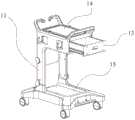
图1是本公开一个实施例提供的推车结构立体图;Fig. 1 is a structural perspective view of a cart provided by an embodiment of the present disclosure;
图2是本公开另一个实施例提供的推车结构立体图;Fig. 2 is a structural perspective view of a cart provided by another embodiment of the present disclosure;
图3是图2的打开抽屉状态下的结构立体图;Fig. 3 is a perspective view of the structure of Fig. 2 when the drawer is opened;
图4是采用图1形成的一种氧合器系统的结构立体图;Fig. 4 is a structural perspective view of an oxygenator system formed in Fig. 1;
图5是图4的另一视图;Fig. 5 is another view of Fig. 4;
图6是图4的托盘与第二支撑座装配视图;Fig. 6 is an assembly view of the tray of Fig. 4 and the second support seat;
图7是托盘与第二支撑座的正视图;Fig. 7 is a front view of the tray and the second support seat;
图8是图7的A-A剖面图;Fig. 8 is the A-A sectional view of Fig. 7;
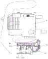
图9是采用图1形成的另一种氧合器系统的结构立体图;Fig. 9 is a structural perspective view of another oxygenator system formed in Fig. 1;
图10是图9中托盘与第二支撑座分离时的结构立体图;Fig. 10 is a perspective view of the structure when the tray in Fig. 9 is separated from the second support seat;
图11是采用图1形成的再一种氧合器系统的结构立体图;Fig. 11 is a structural perspective view of another oxygenator system formed in Fig. 1;
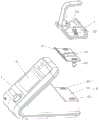
图12是图11中托盘与第一支撑座分离时的结构立体图;Fig. 12 is a perspective view of the structure when the tray in Fig. 11 is separated from the first support seat;
图13是第一设备、转接组件和托盘分离时的结构立体图;Fig. 13 is a perspective view of the structure when the first device, the adapter assembly and the tray are separated;
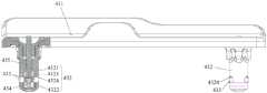
图14是图13中的转接组件的正视图;Figure 14 is a front view of the adapter assembly in Figure 13;
图15是图14中的按压件的剖视图;Fig. 15 is a cross-sectional view of the pressing member in Fig. 14;
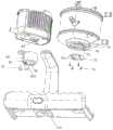
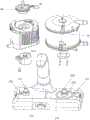
图16是装有血泵的托盘与第二支撑座的装配视图;Fig. 16 is an assembly view of the tray with the blood pump and the second support base;
图17是装有血泵和氧合器的托盘的剖视图;Figure 17 is a cross-sectional view of a tray with a blood pump and an oxygenator;
图18是图17的爆炸图;Figure 18 is an exploded view of Figure 17;
图19是图18的另一视图。FIG. 19 is another view of FIG. 18 .
具体实施方式Detailed ways
以下将结合附图所示的具体实施方式对本发明进行详细描述。但这些实施方式并不限制本发明,本领域的普通技术人员根据这些实施方式所做出的结构、方法、或功能上的变换均包含在本发明的保护范围内。The present invention will be described in detail below in conjunction with specific embodiments shown in the accompanying drawings. However, these embodiments do not limit the present invention, and any structural, method, or functional changes made by those skilled in the art according to these embodiments are included in the protection scope of the present invention.
在本发明中,除非另有明确的规定和限定,“相连”“连接”等术语应做广义理解。例如,可以是固定连接,也可以是可拆卸连接,还可以是可活动连接,或成一体;可以是直接相连,也可以通过中间媒介间接相连,可以是两个元件内部的连通或两个元件的相互作用关系。对于本领域的普通技术人员而言,可以根据具体情况理解上述术语在本发明中的具体含义。本文所使用的术语“垂直的”、“水平的”、“左”、“右”以及类似的表述只是为了说明的目的,并不表示是唯一的实施方式。In the present invention, terms such as "connected" and "connected" should be interpreted in a broad sense unless otherwise specified and limited. For example, it can be a fixed connection, a detachable connection, a movable connection, or an integral body; it can be directly connected or indirectly connected through an intermediary, and it can be the internal communication of two components or two components. interaction relationship. Those of ordinary skill in the art can understand the specific meanings of the above terms in the present invention according to specific situations. The terms "vertical," "horizontal," "left," "right," and similar expressions are used herein for purposes of illustration only and are not intended to represent the only embodiments.
除非另有定义,本文所使用的所有的技术和科学术语与属于本发明的技术领域的技术人员通常理解的含义相同。本文中在本发明的说明书中所使用的术语只是为了描述具体的实施方式的目的,不是旨在于限制本发明。本文所使用的术语“和/或”包括一个或多个相关的所列项目的任意的和所有的组合。此外,下面所描述的本发明不同实施方式中所涉及的技术特征只要彼此之间未构成冲突就可以相互结合。Unless otherwise defined, all technical and scientific terms used herein have the same meaning as commonly understood by one of ordinary skill in the technical field of the invention. The terminology used herein in the description of the present invention is only for the purpose of describing specific embodiments, and is not intended to limit the present invention. As used herein, the term "and/or" includes any and all combinations of one or more of the associated listed items. In addition, the technical features involved in the different embodiments of the present invention described below may be combined with each other as long as there is no conflict with each other.
本公开提供了运载工具或氧合器系统的不同实施例。如图1至图19所示,运载工具包括推车1,支臂3,托盘2。The present disclosure provides different embodiments of a vehicle or oxygenator system. As shown in FIGS. 1 to 19 , the carrier includes a
如图1至图3所示,推车1包括车体11、设在车体11上的第一支撑层14和位于第一支撑层14下方的第二支撑层15。第一支撑层14用于供第一设备放置,第二支撑层15用于供第二设备放置。第二支撑层15位于第一支撑层14的下方,设在车体11底盘上,并配置有多个车轮。车轮优选为万向轮,并安装于底盘的边角位置。第二设备的重量大于第一设备的重量。第一支撑层14和第二支撑层15各自具有承载平台。第二支撑层15的承载平台的承载面积大于第一支撑层14的承载平台的承载面积。As shown in FIGS. 1 to 3 , the
第一设备为控制主机4,包括显示界面,显示界面可以为用户操作界面。如图12所示,第一支撑座42位于显示界面的背面。控制主机4具有提供显示界面的显示屏41,显示屏41可以为触控屏,进而为用户提供可进行触控的操作界面。第二设备包括水箱5和/或氧气瓶6。推车1在其后端(后侧)还设有安装第三设备的承载部,承载部低于第一支撑层14,其大致与第二支撑层15高度一致。在第二设备为水箱5时,第三设备可以为氧气瓶6。The first device is the
控制主机4位于上层的第一支撑层14上,放在最顶端,适合医护人员观察,且显示界面朝向前侧,第一支撑座42安装于控制主机4的后端(显示界面的背面),方便与第二设备或第三设备的线路进行布置,避免线路凌乱,干扰医护人员操作。The
第一支撑层14的前端及后端分别具有推拉把手16,以方便医护人员在前侧或后侧进行推拉操作。车体11上还设有输液架12,便于输液袋或其他医疗用具放置。The front end and the rear end of the first supporting
第一支撑层14和第二支撑层15之间设有相平行的支撑杆17,支撑杆17构置于第二支撑层15(底盘)上将第一支撑层14以平行于第二支撑层15的方式支撑。第一支撑层14和第二支撑层15均向前平行延伸。第一支撑层14还设有诸如抽屉13的容置结构,第一支撑层14的前侧壁形成有供抽屉13放入的敞口。抽屉13可通过滑轨进行支撑,并便于顺滑地前后推拉。Between the
第一支撑层14的前端为悬空端(自由端),仅通过后端与支撑架固定连接。或者,第一支撑层14的前端同样通过支撑杆17与第二支撑层15的前端相连接。The front end of the
第一支撑层14和第二支撑层15之间为第二设备的放置空间,并方便第二支撑座31及支臂3的装配设置。第二支撑座31在水平面上的转动具有死点位置,其可以转动至接触到支撑杆17为止。进而支撑杆17不仅支撑第一支撑层14,还能够对第二支撑座31的转动位置进行限位。The space between the
第二支撑层15在支撑杆17的后侧还延伸形成一承托座(承载部),氧气瓶6承载于承托座上,第二支撑层15在支撑杆17的前侧为主承载区,其上承载有水箱5。在一种实施例中,氧气瓶6可以承载于支撑杆17上,便于车体11的简易结构设计。此时,氧气瓶6通过箍带(strap)套箍,并在底部设有将其承托的圆形载座(cylinder mount)进行承托。其中,圆形载座及箍带均至少高度位置固定地安装于支撑杆17上。进一步地,圆形载座及箍带可以围绕支撑杆17转动,以方便进行收纳。The
如图12所示,第一设备上设有第一支撑座42,第一支撑座42随第一设备移动。支臂3在其延伸方向或长度方向具有第一端和第二端,第一端设在第一支撑层14的底部,第二端设有第二支撑座31。优选的,支臂3的第一端可旋转地设在第一支撑层14的底部。托盘2用于供工作装置设置,可操作地与第一支撑座42或第二支撑座31接合。工作装置包括氧合器7和/或血泵8。As shown in FIG. 12 , a
托盘2可按照期望地安装在第一支撑座42或者第二支撑座31上。图4、图5中存在两个托盘2是为了表明第一支撑座42和第二支撑座31均可以适配安装托盘2,而非实际存在两个托盘2。本实施例的运载工具提供一托盘2,并可切换地装配在第一支撑座42和第二支撑座31上。如图9所示,托盘2装配在第二支撑座31上。如图11所示,托盘2装配在第一支撑座42上。The
如图6所示,托盘2具有用于供工作装置设置的安装位25,安装位25可以包括容置槽,两个安装位25横向布置,中间具有间隔部23。托盘2为大致对称的结构,具有左右两个容置槽。间隔部23为凸出于托盘主体21并将两个安装位25间隔的间隔壁。As shown in FIG. 6 , the
如图6至图8所示,为方便托盘2装配和卸载,托盘2上设有握持部。握持部为握持把手22,方便握持提拉托盘2,以将托盘2安装在第一支撑座42或第二支撑座31或者自第一支撑座42或第二支撑座31将其卸载。(握持)把手可以为图6所示的折弯把手(诸如水龙头形状的半封闭式结构),也可以为环状的环形把手,当然还可以为异形把手等等。把手高于氧合器7和血泵8,避免干涉。As shown in FIGS. 6 to 8 , in order to facilitate the assembly and unloading of the
托盘2可以设有第一连接部,第一支撑座42和第二支撑座31分别设有能与第一连接部可操作分离接合的第二连接部。为方便安装定位托盘2,第一连接部可以包括托盘2的底部形成的凹槽210,第二连接部包括可至少部分嵌入凹槽210中的凸起结构311,以进行定位。优选的,凹槽210和凸起结构311的尺寸相适配,使得凸起结构311嵌入凹槽210后,能使托盘2的水平位置被锁定,即托盘2不能在水平方向移动。The
在一种优选的实施例中,托盘2的底面位于相邻两个安装位25之间的区域向上隆起形成上述凹槽210。凹槽210对应于间隔部23。在另一种实施例中,凸起结构311可以为多个定位柱,托盘2的底部设有供多个定位柱一一插入定位的凹槽210。In a preferred embodiment, the area of the bottom surface of the
支臂3的第一端至少位置固定地连接于第一支撑层14的下方。在本实施例中,支臂3的第一端围绕一竖直轴线可被操作旋转地连接于第一支撑层14的下方,支臂3旋转时的连接部位的位置并不发生改变。支臂3的第一端在第一支撑层14的下方连接在一前支撑杆17上,并在第二端提供一第二支撑座31。第二支撑座31水平(大致与水平面平行的姿态)固定连接于第二端。The first end of the
在一实施例中,支臂3至少包括第一支杆和第二支杆,第一支杆和第二支杆之间相铰接。第一端位于第一支杆的一端(上端),并与第一支撑层14的底部至少位置固定地连接。第一支杆的下端与第二支杆的一端通过一枢转轴相转动连接。枢转轴的轴线(中心线)与第一支杆、第二支杆相垂直。第二端位于第二支杆的一端。第二支撑座31可被操作转动地安装于第二端。第二支撑座31所围绕转动的转轴与第二支杆所围绕转动的转轴(上述枢转轴的中心线)相平行,进而使得第二支撑座31具有更高的转动自由度,便于提供用户期望的使用姿态。第一端可被操作转动地安装于第一支撑层14的底部,其可以围绕一大致沿竖直方向或垂直于第一支撑层14方向的轴线转动,使得第二支撑座31位于不同的水平位置,通过第二支杆的转动调整第二支撑座31的高度位置(即上下位置),通过第二支撑座31的转动调整其相对于水平面的倾角。In one embodiment, the
本实施例中的操作转动并非为自由转动,可以理解为该部件可以通过转动进行不同方位或位置的切换,但其需要用户进行操作,并在转动至期望位置时被定位于该位置。例如,两个部件之间的转动被施加有转动阻尼,或者转动部位还设有诸如定位螺栓或防转螺栓或螺纹箍紧帽等松紧调节组件等等。The operation rotation in this embodiment is not free rotation. It can be understood that the component can switch between different orientations or positions by rotation, but it needs to be operated by the user and is positioned at the desired position when it is rotated. For example, the rotation between the two parts is applied with rotation damping, or the rotation part is also provided with elastic adjustment components such as positioning bolts or anti-rotation bolts or threaded tightening caps, etc.
在一实施例中,第一支杆垂直于第一支撑层14设置,并固定安装于第一支撑层14的底部(底面)。第二支杆为折弯杆,其一端可转动地套设于第一支杆外,通过旋转第二支杆使得第二支撑座31的水平位置改变。第二支撑座31的高度位置(相对于所在地面)在500mm-1000mm之间,优选的其高度位置在500-800mm之间,进一步地在500-700mm之间。In one embodiment, the first pole is arranged perpendicular to the
第二支撑座31被配置为高度可调。当然,在一实施例中,第二支撑座31还可上下移动,具体的,第一支杆的长度可调,其为伸缩杆,通过竖直方向的伸缩实现长度的调节,进而将第二支杆及其上的第二支撑座31的高度进行调节。The
第二支撑座31位于放置空间外,通过水平转动可位于车体11的前侧、左侧、右侧(该左侧、右侧为面对控制主机4显示界面时的左右两侧),并可以按照期望的定位前侧、左侧、右侧,进而在位于病床一侧进行使用时,可将第二支撑座31定位于车体11的左侧或右侧,进行氧合器7或血泵8的使用。在另一使用场景中,可将控制主机4在推车1上搬离并放置在病床上,其第一支撑座42上装有托盘2,托盘2上的氧合器7和血泵8随控制主机4一同移动,方便在病床上直接使用。The
托盘2可拆卸地或可分离地安装于第一支撑座42或第二支撑座31上。具体的,托盘2与第一支撑座42或第二支撑座31通过可操作解除地卡扣连接。即,上述第一连接部和第二连接部可以包括卡扣连接。卡扣连接可以使得托盘2的竖直位置被锁定,即托盘2不能在竖直方向移动。此外,由上文的描述可知,凸起结构311和凹槽210的配合能使托盘2的水平位置被锁定,从而卡扣连接能与凸起结构311、凹槽210共同配合,使得托盘2的水平位置和竖直位置被锁定。当然,在其他实施例中,可以仅通过卡扣连接使托盘2的水平位置和竖直位置被锁定。The
承接上文描述,第一支撑座42和第二支撑座31上设有可至少部分嵌入凹槽210中的凸起结构311。如图10所示,第二支撑座31上设有凸起结构311,凸起结构311为一局部整体凸起,区别于上述实施例中的多个定位柱,该整体凸起更加方便卡入定位。托盘2的底部设有供凸起结构311插入的插槽(即托盘2的凹槽210)。第一支撑座42和第二支撑座31上具有与托盘2相连接的卡座211。凸起结构311位于卡座211上嵌入托盘2的凹槽210中,将托盘2定位。第一支撑座42和托盘2之一或者第二支撑座31和托盘2之一上设有第一卡口213,另一设有可操作解锁地卡入第一卡口213的第一扣体212(公扣)。第一扣体212可以为挂钩。具体的,在第一卡口213内可以设有第一挡块214,第一挡块214提供母扣结构,第一扣体212与第一挡块214形成卡扣结构,第一扣体212可扣合在第一挡块214上。第一扣体212和第一挡块214之一可被操作移动设置解除卡扣。第一扣体212和第一挡块214的初始位置位于扣合位置。Following the above description, the first supporting
第一支撑座42和托盘2之一或者第二支撑座31和托盘2之一上设有第一按钮24,第一扣体212和第一挡块214之一被设有第二弹性件215进行施力,使其位于扣合位置。在第一按钮24被施力将第一扣体212和第一挡块214之一沿抵抗第二弹性件215施力方向运动使其脱离扣合位置,进而解除锁定,方便托盘2从第一支撑座42或第二支撑座31卸载。如图16所示,第一按钮24可以位于托盘上盖26和托盘下盖27之间。One of the
如图8所示,托盘主体21的前侧设有第一按钮24,第一按钮24可被沿前后方向摁压。第一按钮24的内端连接一内板,内板固定有多个朝向下方的第一扣体212。第一支撑座42和第二支撑座31的凸起结构311的上端面设有多个第一卡口213,多个第一扣体212与多个第一卡口213一一对应设置。在凸起结构311的内部设有第一挡块214,第一挡块214与第一卡口213一一对应设置。抓住握持把手22将托盘2自上而下放置,将第一支撑座42和第二支撑座31的凸起结构311嵌入到托盘2的凹槽210中进行定位对准。第一扣体212插入到第一卡口213中,继续向下推入第一扣体212使其与第一挡块214扣合,实现位置锁定。内板的内侧具有一(圆柱)弹簧,弹簧被内板挤压压缩,向内板施加推动内板向前运动的弹力,进而使得第一扣体212的初始位置位于可与第一挡块214相扣合的扣合位置。As shown in FIG. 8 , a
在需要卸载托盘2时,摁压第一按钮24,第一按钮24推动内板向后移动(图8为向右移动),内板带动多个第一扣体212向后移动使其与第一挡块214脱离进而解除扣合,此时另一只手抓住握持把手22向上拉动托盘2即可将托盘2卸载。When the
在一实施例中,如图12和图13所示,第一支撑座42设有与其可操作分离地连接的转接组件43。转接组件43上设有上述第二连接部,从而设有第一连接部的托盘2可以与设有第二连接部的转接组件43可操作分离地接合。托盘2可以通过转接组件43与第一设备连接。当托盘2安装于第一支撑座42时,需要将转接组件43安装至第一设备;当托盘2安装于第二支撑座31时,可以将转接组件43从第一设备拆卸下,使运载工具的结构更简洁,方便用户使用。In one embodiment, as shown in FIGS. 12 and 13 , the
具体的,第一支撑座42设有用于安装转接组件43的安装平面422。安装平面422内设有向下延伸的安装槽421。转接组件设有用于插入安装槽421内的插入部432。其中,插入部432被配置为具有插入到安装槽421中且至少其竖直位置被限位而无法脱离安装槽421的锁定状态。插入部432还设有通过按压使其自锁定状态切换至允许脱离安装槽421的解锁状态的按压件。Specifically, the
在一种实施例中,插入部432还设有位于按压件周侧的活动件和顶抵于按压件的第一弹性件。第一弹性件被压缩或释放能使按压件在放松位和按压位之间切换。具体的,第一弹性件被释放,使按压件位于放松位,活动件被按压件顶抵而沿按压件径向向外移动,使插入部432处于锁定状态;第一弹性件被压缩,使按压件位于按压位,活动件沿按压件径向向内移动,使插入部432处于解锁状态。In one embodiment, the
如图14所示,转接组件43可以包括用于安装托盘2的第一安装座431,第一安装座431上可以设有用于嵌入托盘2的凹槽210中的凸起结构311。插入部432固定连接于第一安装座431的下方。按压件435的侧面可以设有用于收容部分活动件433的第一收容槽4351。按压件435位于放松位时,活动件433被按压件435顶抵而径向凸出插入部432,从而部分活动件433能被安装槽421内的第二收容槽收容而将插入部432和第一设备锁定。按压件435位于按压位时,部分活动件433被第一收容槽4351收容而完全位于插入部432内。As shown in FIG. 14 , the
按压件435可以为沿轴向延伸的按压杆,轴向可以是竖直方向或大致与竖直方向平行的方向。插入部432内还设有抵接于按压件435下方用于为按压件435提供向上复位的弹力的第一弹性件434。第一弹性件434可以是弹簧,其两端分别与插入部432的底部和按压件435抵压。当向按压件435施加向下的外力时,第一弹性件434被压缩,按压件435从放松位切换至按压位;当不向按压件435施加外力时,按压件435被第一弹性件434向上顶抵,处于放松位。The pressing
按压件435的顶部沿轴向延伸直至贯穿第一安装座431,从而按压件435的顶部裸露,以便于工作人员按压。按压件435还设有止挡部4352,止挡部4352使得按压件435在轴向上形成外部尺寸不同的两个区域段,上述两个区域段为位于上方的第一区域段M和位于下方的第二区域段N。如图15所示,第一区域段M的外部尺寸小于第二区域段N的外部尺寸,止挡部4352可以理解为圆轴的轴肩或是柱体外壁上的台阶结构。The top of the
插入部432形成有与第二区域段N配合的空腔4323,第一弹性件434也位于空腔4323内,插入部432底部的侧壁上设有与活动件433配合的开孔4324,开孔4324与空腔4323连通。开孔4324位于外壁面的部分的尺寸小于活动件433的尺寸,使活动件433不会完全脱落于插入部432外。插入部432第二区域段N的外侧壁上内陷形成有第一收容槽4351。当按压件435处于放松位时,活动件433与第二区域段N外侧壁不设有第一收容槽4351的部分抵接,此时,活动件433位于上述开孔4324内且部分裸露于插入部432外侧,以与第一设备卡接,从而使插入部432和第一设备固定相连。第一设备可以设有与活动件433配合的第二收容槽。当向下按压按压件435时,第二区域段N外侧壁上的第一收容槽4351下移至活动件433处,第一收容槽4351为活动件433提供了一回缩空间,从而使得活动件433能与第一设备的第二收容槽脱离,从而能将插入部432从第一设备拆除。The
活动件433可以为球体,相应的,第一收容槽4351可以为弧形。当然在其他实施例中,活动件433和第一收容槽4351的形状可以为其他形状,例如梯形、其他多边形等。为了便于在插入部432内安装按压件435,插入部432分体设置。具体地,插入部432包括插入部主体4321和可拆卸设于插入部主体4321底部的端盖4322。The
优选的,转接组件设有多个插入部432,安装平面422设有多个安装槽421。多个插入部432一一对应插入多个安装槽421内,使转接组件的水平位置被锁定。优选的,在第一安装座431下方可以设置两个插入部432,两个插入部432分别与托盘2的两个安装位25相对应,可以使托盘2的安装更稳定。相应的,第一支撑座42在安装平面422设有两个安装槽421。Preferably, the adapter assembly is provided with a plurality of
在一实施例中,工作装置包括氧合器7和血泵8,托盘2的安装位25包括用于安装氧合器7的第一安装位216和用于安装血泵8的第二安装位223。如图18所示,第一安装位216的底面和第二安装位223的底面齐平。也即,托盘2的底面除了位于第一安装位216和第二安装位223之间的区域向上隆起形成凹槽210,其他区域均为平面。如此设置,可以使得托盘2结构简单,便于其与第一支撑座42或第二支撑座31接合。In one embodiment, the working device includes an
其中,第一安装位216设有用于与氧合器7的排水孔74对接的排水槽222。优选的,如图13和图19所示,第一安装位216的顶面低于第二安装位223的顶面,从而可以防止氧合器7排出的水进入血泵8的马达,避免马达烧机。还有,氧合器7的高度一般高于血泵8,当第一安装位216的顶面低于第二安装位223的顶面时,可以使氧合器7的顶面和血泵8的顶面大致齐平,使结构布局更均匀合理。进而,氧合器7位于第一安装位216时的血液入口76和血泵8位于第二安装位223时的血液出口85可以被设置为在高度上大致齐平,即血液入口76和血液出口85大致位于同一水平面,使得连接血泵8和氧合器7的管路尽可能平直,避免弯曲,优化了整体的布局。血泵8的血液出口85设置在其泵头86上。Wherein, the
在本实施方式中,氧合器7可拆卸地或可分离地安装于托盘2的第一安装位216上。具体的,氧合器7的底部可以设有第一凹陷部71,第一安装位216上可以设有可至少部分嵌入第一凹陷部71中的第一凸起部220。具体的,如图18和图19所示,第一凹陷部71大致位于氧合器7的中心处,第一凸起部220大致位于第一安装位216的中心处,方便对接定位。为了阻止氧合器7安装后在周向上产生转动,可以在第一凸起部220和第一凹陷部71设置限位直边,或者,如图19所示,在第一安装位216的第一凸起部220的一侧设置第一限位凸起221,在氧合器7的底部设置能容纳限位凸起的第一限位槽72。In this embodiment, the
优选的,氧合器7可被操作解除地与第一安装位216卡扣连接。为实现氧合器7和第一安装位216的卡扣连接,在第一安装位216和氧合器7之间设置第一过渡件73。如图18所示,第一过渡件73可以通过螺钉75等紧固件可拆卸地固定于氧合器7的底面。Preferably, the
第一过渡件73可以大致呈圆形平板状,且第一过渡件73的中心设有供第一凸起部220穿过的第一通孔731。第一过渡件73和氧合器7的底部形成第二卡口77,第一安装位216设有可操作解锁地卡入第二卡口77的第二扣体217(公扣)。第二扣体217可以为挂钩。第一过渡件73靠近第二卡口77的一侧壁面形成第二挡块218,第二挡块218提供母扣结构,第二扣体217与第二挡块218形成卡扣结构,第二扣体217可扣合在第二挡块218上。第二扣体217可被移动以解除卡扣。第二扣体217和第二挡块218的初始位置位于扣合位置。The
可以在托盘2上设置氧合器解锁按钮28,第二扣体217被设有第三弹性件219进行施力,使其位于扣合位置。按压氧合器解锁按钮28,可以使第二扣体217沿抵抗第三弹性件219施力方向运动,使第二扣体217脱离扣合位置,进而解除锁定,方便氧合器7从第一安装位216卸载。氧合器解锁按钮28可以位于托盘上盖26和托盘下盖27之间。An
如图17所示,托盘主体21的右侧设有氧合器解锁按钮28,氧合器解锁按钮28可被沿左右方向摁压。在其他实施例中,氧合器解锁按钮28的安装位25置可以是托盘2的其他方位,本申请不做唯一的限定。氧合器解锁按钮28的内端与第二扣体217相连。第一过渡件73靠近第一通孔731的右端面形成第二挡块218。将连接有第一过渡件73的氧合器7自上而下放置至第一安装位216,将第一凸起部220和第一限位凸起221嵌入到氧合器7的第一凹陷部71和第一限位槽72内进行定位对准。第二扣体217先位于第一通孔731中,继续向下推入,第二扣体217插入到第二卡口77中,第二扣体217和第二挡块218扣合,实现位置锁定。第二扣体217的左侧具有一(圆柱)弹簧,弹簧向第二扣体217施加向右运动的弹力,进而使得第二扣体217的初始位置位于可与第二挡块218相扣合的扣合位置。As shown in FIG. 17 , an
在需要卸载氧合器7时,摁压氧合器解锁按钮28,氧合器解锁按钮28推动弹簧向左移动,第二扣体217失去弹簧对其施加的向右的弹力,从而第二扣体217向左移动使第二扣体217与第二挡块218脱离,进而解除第一安装位216和第一过渡件73的卡合,此时另一只手向上拉动氧合器7即可将氧合器7卸载。When the
具体的,第一凸起部220和第一限位凸起221被上述排水槽222围设。排水槽222具有两个出水口,可以设置在托盘2的同一侧。如图19所示,两个出水口设于设有氧合器解锁按钮28的一侧。Specifically, the first protruding
在本实施方式中,血泵8可被操作解除地与第二安装位223卡扣连接。为实现血泵8和第二安装位223的卡扣连接,在第二安装位223和血泵8之间设置第二过渡件83。如图18所示,第二过渡件83可以通过螺钉75等紧固件可拆卸地固定于氧合器7的底面。第二过渡件83可以设有卡钩833,血泵8的底面设有能与卡钩833卡合的卡槽84。In this embodiment, the
具体的,第二过渡件83的底部可以设有第二凹陷部81,第二安装位223上可以设有可至少部分嵌入第二凹陷部81中的第二凸起部227。如图18和图19所示,第二凹陷部81大致位于第二过渡件83的中心处,第二凸起部227大致位于第二安装位223的中心处,方便对接定位。为了阻止血泵8安装后在周向上产生转动,可以在第二凸起部227和第二凹陷部81设置限位直边,或者,如图18和图19所示,在第二安装位223的第二凸起部227的一侧设置第二限位凸起228,在第二过渡件83的底部设置能容纳限位凸起的第二限位槽82。Specifically, the bottom of the
为了使氧合器7的血液入口76和血泵8的血液出口85齐平,除了设置第一安装位216的顶面低于第二安装位223的顶面,还可以设置第二过渡件83的高度大于第一过渡件73的高度;或者,使得氧合器7的底面至第一安装位216的顶面之间的竖直间隔距离小于血泵8的底面至第二安装位223的顶面之间的竖直间隔距离。为了整体布局的合理性以及加工的方便,第一安装位216的顶面和第二安装位223的顶面的高度差可以适当减小,仅保证氧合器7排出的水不会进入血泵8的马达即可。而当第一安装位216的顶面和第二安装位223的顶面的高度差不足以使氧合器7的血液入口76和血泵8的血液出口85齐平时,通过设置第二过渡件83的高度大于第一过渡件73的高度,可以满足血液入口76和血液出口85齐平。此处高度是指竖直方向的长度。In order to make the
第二过渡件83可以大致呈圆柱状,且第二过渡件83的底部中心处设有上述第二凹陷部81。第二过渡件83的顶部可以适当挖空多余部分,以减轻重量。上述第二限位槽82可以设在第二过渡件83的外壁面。第二过渡件83靠近底面的侧壁设有垂直于轴向的第三卡口832。第三卡口832与第二凹陷部81相连通。第二安装位223设有可卡入第三卡口832的第三扣体224(公扣)。第三扣体224可以为挂钩。第二过渡件83的第三卡口832下方的侧壁面形成第三挡块225,第三挡块225提供母扣结构,第三扣体224与第三挡块225形成卡扣结构,第三扣体224可扣合在第三挡块225上。第三扣体224可被移动以解除卡扣。第三扣体224和第三挡块225的初始位置位于扣合位置。The
可以在托盘2上设置血泵解锁按钮29,第三扣体224被设有第四弹性件226进行施力,使其位于扣合位置。按压血泵解锁按钮29,可以使第三扣体224沿抵抗第四弹性件226施力方向运动,使第三扣体224脱离扣合位置,进而解除锁定,方便血泵8从第二安装位223卸载。血泵解锁按钮29可以位于托盘上盖26和托盘下盖27之间。A blood
如图17所示,托盘主体21的左侧设有血泵解锁按钮29,血泵解锁按钮29可被沿左右方向摁压。在其他实施例中,血泵解锁按钮29的安装位25置可以是托盘2的其他方位,本申请不做唯一的限定。血泵解锁按钮29的内端与第三扣体224相连。第二过渡件83的第三卡口832下方的侧壁面形成第三挡块225。将连接有第二过渡件83的血泵8自上而下放置至第二安装位223,将第二凸起部227和第二限位凸起228嵌入到氧合器7的第二凹陷部81和第二限位槽82内进行定位对准。第三扣体224先位于第二凹陷部81中,继续向下推入,第三扣体224插入到第三卡口832中,第三扣体224和第三挡块225扣合,实现位置锁定。第三扣体224的右侧具有一(圆柱)弹簧,弹簧向第三扣体224施加向左运动的弹力,进而使得第三扣体224的初始位置位于可与第三挡块225相扣合的扣合位置。As shown in FIG. 17 , a blood
在需要卸载血泵8时,摁压血泵解锁按钮29,血泵解锁按钮29推动弹簧向右移动,第三扣体224失去弹簧对其施加的向左的弹力,从而第三扣体224向右移动使第三扣体224与第三挡块225脱离,进而解除第二安装位223和第二过渡件83的卡合,此时另一只手向上拉动血泵8即可将血泵8卸载。When the
本公开另一个实施例中还提供一种氧合器系统,包括如上任一的运载工具。其中,第一设备为控制主机4,第二设备包括水箱5和氧气瓶6,工作装置包括氧合器7和血泵8。水箱5、氧气瓶6与氧合器7连接,控制主机4与血泵8连接。Another embodiment of the present disclosure also provides an oxygenator system, including any of the above-mentioned delivery vehicles. Among them, the first device is the
由于氧合器系统解决问题的原理、以及能够取得的技术效果与上述运载工具相似,因此氧合器系统的实施可以参见上述运载工具的实施,重复之处不再赘述。Since the problem-solving principle of the oxygenator system and the technical effects that can be obtained are similar to those of the above-mentioned delivery vehicles, the implementation of the oxygenator system can refer to the implementation of the above-mentioned delivery vehicles, and the repetition will not be repeated.
以上实施例的各技术特征可以进行任意的组合,为使描述简洁,未对上述实施例中的各个技术特征所有可能的组合都进行描述,然而,只要这些技术特征的组合不存在矛盾,都应当认为是本说明书记载的范围。The technical features of the above embodiments can be combined arbitrarily. To make the description concise, all possible combinations of the technical features in the above embodiments are not described. However, as long as there is no contradiction in the combination of these technical features, they should be It is considered to be within the range described in this specification.
以上实施例仅表达了本发明的几种实施方式,其描述较为具体和详细,但并不能因此而理解为对发明专利范围的限制。应当指出的是,对于本领域的普通技术人员来说,在不脱离本发明构思的前提下,还可以做出若干变形和改进,这些都属于本发明的保护范围。因此,本发明专利的保护范围应以所附权利要求为准。The above examples only express several implementation modes of the present invention, and the description thereof is relatively specific and detailed, but it should not be construed as limiting the scope of the patent for the invention. It should be noted that, for those skilled in the art, several modifications and improvements can be made without departing from the concept of the present invention, and these all belong to the protection scope of the present invention. Therefore, the protection scope of the patent for the present invention should be based on the appended claims.
Claims (18)
Priority Applications (2)
| Application Number | Priority Date | Filing Date | Title |
|---|---|---|---|
| CN202310806845.9ACN116807805A (en) | 2022-01-19 | 2022-07-28 | Tray for oxygenator system, adapter assembly, cart and oxygenator system |
| PCT/CN2023/071772WO2023138455A1 (en) | 2022-01-19 | 2023-01-11 | Carrier, and oxygenator system using carrier |
Applications Claiming Priority (2)
| Application Number | Priority Date | Filing Date | Title |
|---|---|---|---|
| CN2022201404163 | 2022-01-19 | ||
| CN202220140416 | 2022-01-19 |
Related Child Applications (1)
| Application Number | Title | Priority Date | Filing Date |
|---|---|---|---|
| CN202310806845.9ADivisionCN116807805A (en) | 2022-01-19 | 2022-07-28 | Tray for oxygenator system, adapter assembly, cart and oxygenator system |
Publications (2)
| Publication Number | Publication Date |
|---|---|
| CN115227519A CN115227519A (en) | 2022-10-25 |
| CN115227519Btrue CN115227519B (en) | 2023-06-02 |
Family
ID=83676502
Family Applications (2)
| Application Number | Title | Priority Date | Filing Date |
|---|---|---|---|
| CN202210893928.1AActiveCN115227519B (en) | 2022-01-19 | 2022-07-28 | Carrier and oxygenator system using same |
| CN202310806845.9APendingCN116807805A (en) | 2022-01-19 | 2022-07-28 | Tray for oxygenator system, adapter assembly, cart and oxygenator system |
Family Applications After (1)
| Application Number | Title | Priority Date | Filing Date |
|---|---|---|---|
| CN202310806845.9APendingCN116807805A (en) | 2022-01-19 | 2022-07-28 | Tray for oxygenator system, adapter assembly, cart and oxygenator system |
Country Status (2)
| Country | Link |
|---|---|
| CN (2) | CN115227519B (en) |
| WO (1) | WO2023138455A1 (en) |
Families Citing this family (2)
| Publication number | Priority date | Publication date | Assignee | Title |
|---|---|---|---|---|
| CN115227519B (en)* | 2022-01-19 | 2023-06-02 | 苏州心擎医疗技术有限公司 | Carrier and oxygenator system using same |
| CN117122476B (en)* | 2023-10-27 | 2024-01-09 | 中山市人民医院 | An ECMO equipment mounting rack that can be used on the hospital bed |
Citations (10)
| Publication number | Priority date | Publication date | Assignee | Title |
|---|---|---|---|---|
| CN1732064A (en)* | 2002-12-27 | 2006-02-08 | 克斯美库股份有限公司 | Positioning device |
| CN101153525A (en)* | 2006-09-30 | 2008-04-02 | Ge医疗系统环球技术有限公司 | Connecting/releasing mechanism and combination device |
| CN104736294A (en)* | 2012-10-15 | 2015-06-24 | 阿尔梅里诺·卡努托 | joint structure |
| CN206777569U (en)* | 2016-12-09 | 2017-12-22 | 四川大学华西医院 | Ecmo transports fixed bolster |
| CN210219143U (en)* | 2019-05-31 | 2020-03-31 | 深圳市理邦精密仪器股份有限公司 | Display support arm and ultrasonic diagnostic equipment |
| CN111228598A (en)* | 2020-03-16 | 2020-06-05 | 美茵(北京)医疗器械研发有限公司 | Extracorporeal life support blood circulation device and flow channel design method thereof |
| CN112023158A (en)* | 2020-08-28 | 2020-12-04 | 巴豪斯医疗器械(苏州)有限公司 | Oxygenator Fixture and Modular ECMO Extracorporeal Membrane Lung Oxygenation Cart Using the Same |
| CN213158283U (en)* | 2020-07-17 | 2021-05-11 | 刘燕 | A closed cardiopulmonary bypass device for cardiac surgery |
| CN113329711A (en)* | 2019-01-25 | 2021-08-31 | 欧赛特有限公司 | Apparatus for transporting biomedical devices |
| CN215460742U (en)* | 2020-12-02 | 2022-01-11 | 深圳汉诺医疗科技有限公司 | Blood treatment equipment |
Family Cites Families (9)
| Publication number | Priority date | Publication date | Assignee | Title |
|---|---|---|---|---|
| US7189352B2 (en)* | 2003-01-14 | 2007-03-13 | Medtronic, Inc. | Extracorporeal blood circuit priming system and method |
| US20130105425A1 (en)* | 2011-10-27 | 2013-05-02 | Daniel Rodriguez | Portable Apparatus for Life Support Equipment |
| JP2016064033A (en)* | 2014-09-25 | 2016-04-28 | テルモ株式会社 | Device attaching/detaching structure and carrier cart having the same |
| CN209713797U (en)* | 2019-01-23 | 2019-12-03 | 苏州心擎医疗技术有限公司 | External monitor |
| IT201900001149A1 (en)* | 2019-01-25 | 2020-07-25 | Eurosets Srl | EQUIPMENT FOR SUPPORTING BIOMEDICAL DEVICES DURING EXTRA-BODY CIRCULATION |
| CN111701102B (en)* | 2020-06-29 | 2022-09-23 | 深圳汉诺医疗科技有限公司 | An extracorporeal membrane oxygenation device |
| CN215023514U (en)* | 2020-12-02 | 2021-12-07 | 深圳汉诺医疗科技有限公司 | Movable extracorporeal membrane oxygenation system for lung |
| CN215504695U (en)* | 2020-12-02 | 2022-01-14 | 深圳汉诺医疗科技有限公司 | A mobile device for loading external membrane lung oxygenation system |
| CN115227519B (en)* | 2022-01-19 | 2023-06-02 | 苏州心擎医疗技术有限公司 | Carrier and oxygenator system using same |
- 2022
- 2022-07-28CNCN202210893928.1Apatent/CN115227519B/enactiveActive
- 2022-07-28CNCN202310806845.9Apatent/CN116807805A/enactivePending
- 2023
- 2023-01-11WOPCT/CN2023/071772patent/WO2023138455A1/ennot_activeCeased
Patent Citations (10)
| Publication number | Priority date | Publication date | Assignee | Title |
|---|---|---|---|---|
| CN1732064A (en)* | 2002-12-27 | 2006-02-08 | 克斯美库股份有限公司 | Positioning device |
| CN101153525A (en)* | 2006-09-30 | 2008-04-02 | Ge医疗系统环球技术有限公司 | Connecting/releasing mechanism and combination device |
| CN104736294A (en)* | 2012-10-15 | 2015-06-24 | 阿尔梅里诺·卡努托 | joint structure |
| CN206777569U (en)* | 2016-12-09 | 2017-12-22 | 四川大学华西医院 | Ecmo transports fixed bolster |
| CN113329711A (en)* | 2019-01-25 | 2021-08-31 | 欧赛特有限公司 | Apparatus for transporting biomedical devices |
| CN210219143U (en)* | 2019-05-31 | 2020-03-31 | 深圳市理邦精密仪器股份有限公司 | Display support arm and ultrasonic diagnostic equipment |
| CN111228598A (en)* | 2020-03-16 | 2020-06-05 | 美茵(北京)医疗器械研发有限公司 | Extracorporeal life support blood circulation device and flow channel design method thereof |
| CN213158283U (en)* | 2020-07-17 | 2021-05-11 | 刘燕 | A closed cardiopulmonary bypass device for cardiac surgery |
| CN112023158A (en)* | 2020-08-28 | 2020-12-04 | 巴豪斯医疗器械(苏州)有限公司 | Oxygenator Fixture and Modular ECMO Extracorporeal Membrane Lung Oxygenation Cart Using the Same |
| CN215460742U (en)* | 2020-12-02 | 2022-01-11 | 深圳汉诺医疗科技有限公司 | Blood treatment equipment |
Also Published As
| Publication number | Publication date |
|---|---|
| CN116807805A (en) | 2023-09-29 |
| CN115227519A (en) | 2022-10-25 |
| WO2023138455A1 (en) | 2023-07-27 |
Similar Documents
| Publication | Publication Date | Title |
|---|---|---|
| CN115227519B (en) | Carrier and oxygenator system using same | |
| US5438938A (en) | Cart with removable tray assembly | |
| KR101844217B1 (en) | Accessory clamp for emergency cots | |
| US20210370995A1 (en) | Portable and modular transportation unit with improved transport capabilities | |
| US6865418B2 (en) | Docking station for defibrillator | |
| CN108791451A (en) | Stroller device | |
| US9883978B2 (en) | Docking systems for medical devices and related devices | |
| US7798456B2 (en) | Transferable patient care equipment support | |
| US11919556B2 (en) | Cart for medical equipment | |
| US20100072730A1 (en) | Fold flat carrier wagon/cart with stowable walls, wheels and handle, and manufacturing methods | |
| CN112023158B (en) | Oxygenator fixing device and modularized ECMO (electro-chemical mechanical mo) extracorporeal membrane pulmonary oxygenation trolley using same | |
| US20080302585A1 (en) | Transport system | |
| EP3131806A2 (en) | Portable medical cart system | |
| US9463819B2 (en) | Portable medical cart system | |
| US20250312205A1 (en) | Mounting apparatus for securing equipment to a patient transport system | |
| US20230096795A1 (en) | Coupling systems for releasably coupling equipment to a patient transport systems | |
| CN213852374U (en) | Oxygenator installing support capable of being fixed fast and modularized ECMO extracorporeal membrane lung oxygenation frame vehicle using same | |
| US20040256838A1 (en) | Compact wheelbarrow and cart assembly, shipping and display methods including hitch and trailing conversions | |
| US6941597B2 (en) | Holding device for medical instruments at a patient's bed | |
| CN118176092A (en) | Workstation with modular construction | |
| WO2025175669A1 (en) | Tool cart |
Legal Events
| Date | Code | Title | Description |
|---|---|---|---|
| PB01 | Publication | ||
| PB01 | Publication | ||
| SE01 | Entry into force of request for substantive examination | ||
| SE01 | Entry into force of request for substantive examination | ||
| GR01 | Patent grant | ||
| GR01 | Patent grant | ||
| CP03 | Change of name, title or address | Address after:Room 801, 802, 803, 804, Building 7, No. 188 Fuchunjiang Road, High-tech Zone, Suzhou City, Jiangsu Province, 215163 Patentee after:Xinqing Medical (Suzhou) Co.,Ltd. Address before:8th Floor, Building 7, No. 188, Fuchunjiang Road, Science and Technology City, High-tech Zone, Huqiu District, Suzhou City, Jiangsu Province 215163 Patentee before:SUZHOU XINQING MEDICAL TECHNOLOGY Co.,Ltd. | |
| CP03 | Change of name, title or address |