CN115224514A - Electrical connection terminal and electrical connection assembly - Google Patents
Electrical connection terminal and electrical connection assemblyDownload PDFInfo
- Publication number
- CN115224514A CN115224514ACN202110402459.4ACN202110402459ACN115224514ACN 115224514 ACN115224514 ACN 115224514ACN 202110402459 ACN202110402459 ACN 202110402459ACN 115224514 ACN115224514 ACN 115224514A
- Authority
- CN
- China
- Prior art keywords
- electrical connection
- connection terminal
- base
- cable
- tabs
- Prior art date
- Legal status (The legal status is an assumption and is not a legal conclusion. Google has not performed a legal analysis and makes no representation as to the accuracy of the status listed.)
- Pending
Links
Images


Classifications
- H—ELECTRICITY
- H01—ELECTRIC ELEMENTS
- H01R—ELECTRICALLY-CONDUCTIVE CONNECTIONS; STRUCTURAL ASSOCIATIONS OF A PLURALITY OF MUTUALLY-INSULATED ELECTRICAL CONNECTING ELEMENTS; COUPLING DEVICES; CURRENT COLLECTORS
- H01R13/00—Details of coupling devices of the kinds covered by groups H01R12/70 or H01R24/00 - H01R33/00
- H01R13/62—Means for facilitating engagement or disengagement of coupling parts or for holding them in engagement
- H01R13/629—Additional means for facilitating engagement or disengagement of coupling parts, e.g. aligning or guiding means, levers, gas pressure electrical locking indicators, manufacturing tolerances
- H—ELECTRICITY
- H01—ELECTRIC ELEMENTS
- H01R—ELECTRICALLY-CONDUCTIVE CONNECTIONS; STRUCTURAL ASSOCIATIONS OF A PLURALITY OF MUTUALLY-INSULATED ELECTRICAL CONNECTING ELEMENTS; COUPLING DEVICES; CURRENT COLLECTORS
- H01R13/00—Details of coupling devices of the kinds covered by groups H01R12/70 or H01R24/00 - H01R33/00
- H01R13/02—Contact members
- H01R13/04—Pins or blades for co-operation with sockets
- B—PERFORMING OPERATIONS; TRANSPORTING
- B60—VEHICLES IN GENERAL
- B60L—PROPULSION OF ELECTRICALLY-PROPELLED VEHICLES; SUPPLYING ELECTRIC POWER FOR AUXILIARY EQUIPMENT OF ELECTRICALLY-PROPELLED VEHICLES; ELECTRODYNAMIC BRAKE SYSTEMS FOR VEHICLES IN GENERAL; MAGNETIC SUSPENSION OR LEVITATION FOR VEHICLES; MONITORING OPERATING VARIABLES OF ELECTRICALLY-PROPELLED VEHICLES; ELECTRIC SAFETY DEVICES FOR ELECTRICALLY-PROPELLED VEHICLES
- B60L53/00—Methods of charging batteries, specially adapted for electric vehicles; Charging stations or on-board charging equipment therefor; Exchange of energy storage elements in electric vehicles
- B60L53/10—Methods of charging batteries, specially adapted for electric vehicles; Charging stations or on-board charging equipment therefor; Exchange of energy storage elements in electric vehicles characterised by the energy transfer between the charging station and the vehicle
- B60L53/14—Conductive energy transfer
- B60L53/16—Connectors, e.g. plugs or sockets, specially adapted for charging electric vehicles
- H—ELECTRICITY
- H01—ELECTRIC ELEMENTS
- H01R—ELECTRICALLY-CONDUCTIVE CONNECTIONS; STRUCTURAL ASSOCIATIONS OF A PLURALITY OF MUTUALLY-INSULATED ELECTRICAL CONNECTING ELEMENTS; COUPLING DEVICES; CURRENT COLLECTORS
- H01R11/00—Individual connecting elements providing two or more spaced connecting locations for conductive members which are, or may be, thereby interconnected, e.g. end pieces for wires or cables supported by the wire or cable and having means for facilitating electrical connection to some other wire, terminal, or conductive member, blocks of binding posts
- H01R11/01—Individual connecting elements providing two or more spaced connecting locations for conductive members which are, or may be, thereby interconnected, e.g. end pieces for wires or cables supported by the wire or cable and having means for facilitating electrical connection to some other wire, terminal, or conductive member, blocks of binding posts characterised by the form or arrangement of the conductive interconnection between the connecting locations
- H—ELECTRICITY
- H01—ELECTRIC ELEMENTS
- H01R—ELECTRICALLY-CONDUCTIVE CONNECTIONS; STRUCTURAL ASSOCIATIONS OF A PLURALITY OF MUTUALLY-INSULATED ELECTRICAL CONNECTING ELEMENTS; COUPLING DEVICES; CURRENT COLLECTORS
- H01R13/00—Details of coupling devices of the kinds covered by groups H01R12/70 or H01R24/00 - H01R33/00
- H01R13/02—Contact members
- H01R13/10—Sockets for co-operation with pins or blades
- H—ELECTRICITY
- H01—ELECTRIC ELEMENTS
- H01R—ELECTRICALLY-CONDUCTIVE CONNECTIONS; STRUCTURAL ASSOCIATIONS OF A PLURALITY OF MUTUALLY-INSULATED ELECTRICAL CONNECTING ELEMENTS; COUPLING DEVICES; CURRENT COLLECTORS
- H01R13/00—Details of coupling devices of the kinds covered by groups H01R12/70 or H01R24/00 - H01R33/00
- H01R13/46—Bases; Cases
- H01R13/533—Bases, cases made for use in extreme conditions, e.g. high temperature, radiation, vibration, corrosive environment, pressure
- H—ELECTRICITY
- H01—ELECTRIC ELEMENTS
- H01R—ELECTRICALLY-CONDUCTIVE CONNECTIONS; STRUCTURAL ASSOCIATIONS OF A PLURALITY OF MUTUALLY-INSULATED ELECTRICAL CONNECTING ELEMENTS; COUPLING DEVICES; CURRENT COLLECTORS
- H01R24/00—Two-part coupling devices, or either of their cooperating parts, characterised by their overall structure
- H—ELECTRICITY
- H01—ELECTRIC ELEMENTS
- H01R—ELECTRICALLY-CONDUCTIVE CONNECTIONS; STRUCTURAL ASSOCIATIONS OF A PLURALITY OF MUTUALLY-INSULATED ELECTRICAL CONNECTING ELEMENTS; COUPLING DEVICES; CURRENT COLLECTORS
- H01R4/00—Electrically-conductive connections between two or more conductive members in direct contact, i.e. touching one another; Means for effecting or maintaining such contact; Electrically-conductive connections having two or more spaced connecting locations for conductors and using contact members penetrating insulation
- H01R4/10—Electrically-conductive connections between two or more conductive members in direct contact, i.e. touching one another; Means for effecting or maintaining such contact; Electrically-conductive connections having two or more spaced connecting locations for conductors and using contact members penetrating insulation effected solely by twisting, wrapping, bending, crimping, or other permanent deformation
- H01R4/18—Electrically-conductive connections between two or more conductive members in direct contact, i.e. touching one another; Means for effecting or maintaining such contact; Electrically-conductive connections having two or more spaced connecting locations for conductors and using contact members penetrating insulation effected solely by twisting, wrapping, bending, crimping, or other permanent deformation by crimping
- H—ELECTRICITY
- H01—ELECTRIC ELEMENTS
- H01R—ELECTRICALLY-CONDUCTIVE CONNECTIONS; STRUCTURAL ASSOCIATIONS OF A PLURALITY OF MUTUALLY-INSULATED ELECTRICAL CONNECTING ELEMENTS; COUPLING DEVICES; CURRENT COLLECTORS
- H01R13/00—Details of coupling devices of the kinds covered by groups H01R12/70 or H01R24/00 - H01R33/00
- H01R13/02—Contact members
- H01R13/10—Sockets for co-operation with pins or blades
- H01R13/11—Resilient sockets
- H01R13/113—Resilient sockets co-operating with pins or blades having a rectangular transverse section
- H—ELECTRICITY
- H01—ELECTRIC ELEMENTS
- H01R—ELECTRICALLY-CONDUCTIVE CONNECTIONS; STRUCTURAL ASSOCIATIONS OF A PLURALITY OF MUTUALLY-INSULATED ELECTRICAL CONNECTING ELEMENTS; COUPLING DEVICES; CURRENT COLLECTORS
- H01R2201/00—Connectors or connections adapted for particular applications
- H01R2201/26—Connectors or connections adapted for particular applications for vehicles
- H—ELECTRICITY
- H01—ELECTRIC ELEMENTS
- H01R—ELECTRICALLY-CONDUCTIVE CONNECTIONS; STRUCTURAL ASSOCIATIONS OF A PLURALITY OF MUTUALLY-INSULATED ELECTRICAL CONNECTING ELEMENTS; COUPLING DEVICES; CURRENT COLLECTORS
- H01R4/00—Electrically-conductive connections between two or more conductive members in direct contact, i.e. touching one another; Means for effecting or maintaining such contact; Electrically-conductive connections having two or more spaced connecting locations for conductors and using contact members penetrating insulation
- H01R4/02—Soldered or welded connections
- H01R4/023—Soldered or welded connections between cables or wires and terminals
- H—ELECTRICITY
- H01—ELECTRIC ELEMENTS
- H01R—ELECTRICALLY-CONDUCTIVE CONNECTIONS; STRUCTURAL ASSOCIATIONS OF A PLURALITY OF MUTUALLY-INSULATED ELECTRICAL CONNECTING ELEMENTS; COUPLING DEVICES; CURRENT COLLECTORS
- H01R4/00—Electrically-conductive connections between two or more conductive members in direct contact, i.e. touching one another; Means for effecting or maintaining such contact; Electrically-conductive connections having two or more spaced connecting locations for conductors and using contact members penetrating insulation
- H01R4/02—Soldered or welded connections
- H01R4/029—Welded connections
- H—ELECTRICITY
- H01—ELECTRIC ELEMENTS
- H01R—ELECTRICALLY-CONDUCTIVE CONNECTIONS; STRUCTURAL ASSOCIATIONS OF A PLURALITY OF MUTUALLY-INSULATED ELECTRICAL CONNECTING ELEMENTS; COUPLING DEVICES; CURRENT COLLECTORS
- H01R4/00—Electrically-conductive connections between two or more conductive members in direct contact, i.e. touching one another; Means for effecting or maintaining such contact; Electrically-conductive connections having two or more spaced connecting locations for conductors and using contact members penetrating insulation
- H01R4/10—Electrically-conductive connections between two or more conductive members in direct contact, i.e. touching one another; Means for effecting or maintaining such contact; Electrically-conductive connections having two or more spaced connecting locations for conductors and using contact members penetrating insulation effected solely by twisting, wrapping, bending, crimping, or other permanent deformation
- H01R4/18—Electrically-conductive connections between two or more conductive members in direct contact, i.e. touching one another; Means for effecting or maintaining such contact; Electrically-conductive connections having two or more spaced connecting locations for conductors and using contact members penetrating insulation effected solely by twisting, wrapping, bending, crimping, or other permanent deformation by crimping
- H01R4/183—Electrically-conductive connections between two or more conductive members in direct contact, i.e. touching one another; Means for effecting or maintaining such contact; Electrically-conductive connections having two or more spaced connecting locations for conductors and using contact members penetrating insulation effected solely by twisting, wrapping, bending, crimping, or other permanent deformation by crimping for cylindrical elongated bodies, e.g. cables having circular cross-section
- H01R4/184—Electrically-conductive connections between two or more conductive members in direct contact, i.e. touching one another; Means for effecting or maintaining such contact; Electrically-conductive connections having two or more spaced connecting locations for conductors and using contact members penetrating insulation effected solely by twisting, wrapping, bending, crimping, or other permanent deformation by crimping for cylindrical elongated bodies, e.g. cables having circular cross-section comprising a U-shaped wire-receiving portion
- H—ELECTRICITY
- H01—ELECTRIC ELEMENTS
- H01R—ELECTRICALLY-CONDUCTIVE CONNECTIONS; STRUCTURAL ASSOCIATIONS OF A PLURALITY OF MUTUALLY-INSULATED ELECTRICAL CONNECTING ELEMENTS; COUPLING DEVICES; CURRENT COLLECTORS
- H01R4/00—Electrically-conductive connections between two or more conductive members in direct contact, i.e. touching one another; Means for effecting or maintaining such contact; Electrically-conductive connections having two or more spaced connecting locations for conductors and using contact members penetrating insulation
- H01R4/10—Electrically-conductive connections between two or more conductive members in direct contact, i.e. touching one another; Means for effecting or maintaining such contact; Electrically-conductive connections having two or more spaced connecting locations for conductors and using contact members penetrating insulation effected solely by twisting, wrapping, bending, crimping, or other permanent deformation
- H01R4/18—Electrically-conductive connections between two or more conductive members in direct contact, i.e. touching one another; Means for effecting or maintaining such contact; Electrically-conductive connections having two or more spaced connecting locations for conductors and using contact members penetrating insulation effected solely by twisting, wrapping, bending, crimping, or other permanent deformation by crimping
- H01R4/20—Electrically-conductive connections between two or more conductive members in direct contact, i.e. touching one another; Means for effecting or maintaining such contact; Electrically-conductive connections having two or more spaced connecting locations for conductors and using contact members penetrating insulation effected solely by twisting, wrapping, bending, crimping, or other permanent deformation by crimping using a crimping sleeve
Landscapes
- Engineering & Computer Science (AREA)
- Power Engineering (AREA)
- Transportation (AREA)
- Mechanical Engineering (AREA)
- Connections Effected By Soldering, Adhesion, Or Permanent Deformation (AREA)
- Coupling Device And Connection With Printed Circuit (AREA)
- Details Of Connecting Devices For Male And Female Coupling (AREA)
Abstract
Translated fromChinese
Description
Translated fromChinese技术领域technical field
本发明涉及一种电连接端子和包括该电连接端子的电连接组件。The present invention relates to an electrical connection terminal and an electrical connection assembly including the electrical connection terminal.
背景技术Background technique
在现有技术中,为了实现电动汽车的快速充电,用于电连接电动汽车的充电电池的电连接端子必须承载较大的电流。但是,目前的电连接端子的结构多为单一插片,单插片结构的长度较大,这会导致电流流经的路径较长,体电阻较高,发热量较大,对充电电流的大小造成了极大的限制,不能应用于更高的充电电流。In the prior art, in order to realize the fast charging of the electric vehicle, the electrical connection terminals for electrically connecting the rechargeable battery of the electric vehicle must carry a relatively large current. However, the structure of the current electrical connection terminal is mostly a single blade, and the length of the single blade structure is relatively large, which will lead to a longer path for the current to flow through, a higher body resistance, a higher heat generation, and a greater impact on the size of the charging current. Causes a great limitation and cannot be applied to higher charging currents.
发明内容SUMMARY OF THE INVENTION
本发明的目的旨在解决现有技术中存在的上述问题和缺陷的至少一个方面。The purpose of the present invention is to solve at least one aspect of the above-mentioned problems and deficiencies in the prior art.
根据本发明的一个方面,提供一种电连接端子,包括:基部;和多个插片,连接到所述基部上,所述多个插片彼此间隔开,且每个插片适于以插拔的方式与对配端子对配。According to one aspect of the present invention, there is provided an electrical connection terminal, comprising: a base; and a plurality of tabs connected to the base, the plurality of tabs being spaced apart from each other, and each tab being adapted to be inserted into the base The way of pulling is matched with the mating terminal.
根据本发明的一个实例性的实施例,所述多个插片沿所述基部的厚度方向朝下延伸,以适于与多个对配端子同时对配。According to an exemplary embodiment of the present invention, the plurality of inserts extend downward along the thickness direction of the base, so as to be suitable for mating with a plurality of mating terminals at the same time.
根据本发明的另一个实例性的实施例,所述电连接端子包括并排布置的两个插片,所述两个插片分别连接到所述基部的宽度方向的两侧并与所述基部的宽度方向垂直。According to another exemplary embodiment of the present invention, the electrical connection terminal includes two protruding pieces arranged side by side, the two protruding pieces are respectively connected to both sides of the base portion in the width direction and are connected with the base portion. The width direction is vertical.
根据本发明的另一个实例性的实施例,所述电连接端子包括三个插片,所述三个插片并排设置并与所述基部的宽度方向垂直。According to another exemplary embodiment of the present invention, the electrical connection terminal includes three inserts arranged side by side and perpendicular to the width direction of the base.
根据本发明的另一个实例性的实施例,所述三个插片中的两个分别连接到所述基部的宽度方向的两侧,剩余的一个插片连接到所述基部的宽度方向的中间部位。According to another exemplary embodiment of the present invention, two of the three tabs are connected to both sides of the base in the width direction, respectively, and the remaining one tab is connected to the middle of the base in the width direction part.
根据本发明的另一个实例性的实施例,所述电连接端子包括三个插片,所述三个插片中的两个并排设置并与所述基部的宽度方向垂直,所述三个插片中剩余的一个被设置成与所述基部的长度方向垂直。According to another exemplary embodiment of the present invention, the electrical connection terminal includes three inserts, two of the three inserts are arranged side by side and are perpendicular to the width direction of the base, the three inserts The remaining one of the sheets is arranged perpendicular to the length of the base.
根据本发明的另一个实例性的实施例,所述三个插片中的两个分别连接到所述基部的宽度方向的两侧,剩余的一个插片连接到所述基部的长度方向的一端。According to another exemplary embodiment of the present invention, two of the three inserts are respectively connected to both sides of the base in the width direction, and the remaining one is connected to one end of the base in the length direction .
根据本发明的另一个实例性的实施例,所述多个插片沿所述基部的宽度方向排成一行;或者所述多个插片沿所述基部的长度方向排成一列;或者所述多个插片沿所述基部的宽度方向和长度方向布置成多行多列。According to another exemplary embodiment of the present invention, the plurality of inserts are arranged in a row along the width direction of the base; or the plurality of inserts are arranged in a column along the length of the base; or the The plurality of tabs are arranged in rows and columns along the width direction and the length direction of the base.
根据本发明的另一个实例性的实施例,所述电连接端子还包括连接部,所述连接部与所述基部连接并电连接到电缆的端部上。According to another exemplary embodiment of the present invention, the electrical connection terminal further includes a connection portion connected to the base portion and electrically connected to the end portion of the cable.
根据本发明的另一个实例性的实施例,所述连接部呈平板状,且平板状的连接部适于焊接到电缆的端部上;或者所述连接部呈圆筒状,且圆筒状的连接部适于压接到电缆的端部上;或者所述连接部呈侧翼状,且侧翼状的连接部适于压接到电缆的端部上。According to another exemplary embodiment of the present invention, the connecting portion is in the shape of a flat plate, and the flat connecting portion is suitable for welding to the end portion of the cable; or the connecting portion is in the shape of a cylinder, and the cylindrical shape is The connecting portion is suitable for being crimped to the end of the cable; or the connecting portion is in the shape of a flank, and the connecting portion of the flank is suitable for being crimped to the end of the cable.
根据本发明的另一个实例性的实施例,所述连接部的延伸方向与所述基部的长度方向平行或者与所述基部的长度方向成预定夹角。According to another exemplary embodiment of the present invention, the extending direction of the connecting portion is parallel to the length direction of the base portion or forms a predetermined angle with the length direction of the base portion.
根据本发明的另一个实例性的实施例,所述电连接端子包括两个插片,所述两个插片分别连接到所述基部的宽度方向的两侧,使得所述电连接端子呈U型。According to another exemplary embodiment of the present invention, the electrical connection terminal includes two inserts, and the two inserts are respectively connected to both sides in the width direction of the base, so that the electrical connection terminal is U-shaped type.
根据本发明的另一个实例性的实施例,所述多个插片中的至少一些插片相互平行且并排布置。According to another exemplary embodiment of the present invention, at least some of the plurality of blades are arranged parallel to each other and side by side.
根据本发明的另一个方面,提供一种电连接组件,包括:前述电连接端子;和导电件,其端部与所述电连接端子的基部电连接。According to another aspect of the present invention, there is provided an electrical connection assembly comprising: the aforementioned electrical connection terminal; and a conductive member, the end of which is electrically connected to the base of the electrical connection terminal.
根据本发明的一个实例性的实施例,所述导电件的端部包括扁平状的连接表面,所述连接表面与所述基部的上表面或下表面接触并电连接。According to an exemplary embodiment of the present invention, the end portion of the conductive member includes a flat connecting surface, and the connecting surface is in contact with and electrically connected to the upper surface or the lower surface of the base portion.
根据本发明的另一个实例性的实施例,所述导电件为电缆或汇流条。According to another exemplary embodiment of the present invention, the conductive member is a cable or a bus bar.
根据本发明的另一个实例性的实施例,所述电连接组件还包括连接器壳体;所述电连接端子固定安装在所述连接器壳体内。According to another exemplary embodiment of the present invention, the electrical connection assembly further includes a connector housing; the electrical connection terminal is fixedly installed in the connector housing.
根据本发明的另一个方面,提供一种电连接组件,包括:第一电连接端子和对配端子。第一电连接端子包括:第一基部;和多个第一插片,连接到第一基部上并彼此间隔开。所述对配端子包括与所述第一插片对配的第一对配端。According to another aspect of the present invention, an electrical connection assembly is provided, comprising: a first electrical connection terminal and a mating terminal. The first electrical connection terminal includes: a first base; and a plurality of first tabs connected to the first base and spaced apart from each other. The mating terminal includes a first mating end matched with the first insert.
根据本发明的一个实例性的实施例,所述电连接组件还包括第二电连接端子,第二电连接端子包括:第二基部;和多个第二插片,连接到第二基部上并彼此间隔开。所述对配端子还包括与所述第二插片对配的第二对配端。According to an exemplary embodiment of the present invention, the electrical connection assembly further includes a second electrical connection terminal, and the second electrical connection terminal includes: a second base; and a plurality of second inserts connected to the second base and spaced from each other. The mating terminal further includes a second mating end matched with the second insert.
在根据本发明的前述各个实例性的实施例中,电连接端子采用了多个并联的插片,因此减小了电连接端子的长度和电流流经的路径,而且电流在分流后流经的路径更短,因此,本发明的电连接端子的体电阻较低,发热更小,更适应大电流应用。In each of the foregoing exemplary embodiments according to the present invention, the electrical connection terminal adopts a plurality of parallel inserts, thus reducing the length of the electrical connection terminal and the path through which the current flows. The path is shorter, therefore, the electrical connection terminal of the present invention has lower bulk resistance, less heat generation, and is more suitable for high-current applications.
在根据本发明的前述各个实例性的实施例中,多个插片增加了电连接端子的横截面积和表面面积,从而提高了电连接端子的等效电流截面积和有效散热面积,使得电连接端子更适应大电流应用。In each of the foregoing exemplary embodiments according to the present invention, the plurality of inserts increase the cross-sectional area and surface area of the electrical connection terminal, thereby increasing the equivalent current cross-sectional area and effective heat dissipation area of the electrical connection terminal, so that the electrical Connection terminals are more suitable for high current applications.
通过下文中参照附图对本发明所作的描述,本发明的其它目的和优点将显而易见,并可帮助对本发明有全面的理解。Other objects and advantages of the present invention will be apparent from the following description of the present invention with reference to the accompanying drawings, and may assist in a comprehensive understanding of the present invention.
附图说明Description of drawings
图1显示根据本发明的一个实例性的实施例的电连接组件的立体示意图;1 shows a schematic perspective view of an electrical connection assembly according to an exemplary embodiment of the present invention;
图2显示图1所示的电缆、与电缆连接的电连接端子和与电连接端子对配的对配端子的立体示意图;FIG. 2 shows a schematic perspective view of the cable shown in FIG. 1 , the electrical connection terminal connected to the cable, and the mating terminal matched with the electrical connection terminal;
图3显示图2所示的电缆和电连接端子的立体示意图;FIG. 3 shows a schematic perspective view of the cable and the electrical connection terminal shown in FIG. 2;
图4显示图1所示的汇流条和与汇流条连接的电连接端子的立体示意图;FIG. 4 shows a schematic perspective view of the bus bar shown in FIG. 1 and the electrical connection terminals connected to the bus bar;
图5显示根据本发明的另一个实例性的实施例的电缆和与电缆连接的电连接端子的立体示意图;5 shows a schematic perspective view of a cable and an electrical connection terminal connected to the cable according to another exemplary embodiment of the present invention;
图6显示根据本发明的另一个实例性的实施例的电缆和与电缆连接的电连接端子的立体示意图;6 shows a schematic perspective view of a cable and an electrical connection terminal connected to the cable according to another exemplary embodiment of the present invention;
图7显示根据本发明的另一个实例性的实施例的电缆和与电缆连接的电连接端子的立体示意图;7 shows a schematic perspective view of a cable and an electrical connection terminal connected to the cable according to another exemplary embodiment of the present invention;
图8显示根据本发明的另一个实例性的实施例的电缆和与电缆连接的电连接端子的立体示意图;8 shows a schematic perspective view of a cable and an electrical connection terminal connected to the cable according to another exemplary embodiment of the present invention;
图9显示根据本发明的另一个实例性的实施例的电缆和与电缆连接的电连接端子的立体示意图;9 shows a schematic perspective view of a cable and an electrical connection terminal connected to the cable according to another exemplary embodiment of the present invention;
图10显示根据本发明的另一个实例性的实施例的电缆和与电缆连接的电连接端子的立体示意图;10 shows a schematic perspective view of a cable and an electrical connection terminal connected to the cable according to another exemplary embodiment of the present invention;
图11显示根据本发明的另一个实例性的实施例的电缆和与电缆连接的电连接端子的立体示意图;11 shows a schematic perspective view of a cable and an electrical connection terminal connected to the cable according to another exemplary embodiment of the present invention;
图12显示根据本发明的另一个实例性的实施例的电缆和与电缆连接的电连接端子的立体示意图;12 shows a schematic perspective view of a cable and an electrical connection terminal connected to the cable according to another exemplary embodiment of the present invention;
图13显示根据本发明的另一个实例性的实施例的电缆和与电缆连接的电连接端子的立体示意图;13 shows a schematic perspective view of a cable and an electrical connection terminal connected to the cable according to another exemplary embodiment of the present invention;
图14显示根据本发明的另一个实例性的实施例的电缆和与电缆连接的电连接端子的立体示意图。14 shows a schematic perspective view of a cable and an electrical connection terminal connected to the cable according to another exemplary embodiment of the present invention.
具体实施方式Detailed ways
下面通过实施例,并结合附图,对本发明的技术方案作进一步具体的说明。在说明书中,相同或相似的附图标号指示相同或相似的部件。下述参照附图对本发明实施方式的说明旨在对本发明的总体发明构思进行解释,而不应当理解为对本发明的一种限制。The technical solutions of the present invention will be further described in detail below through embodiments and in conjunction with the accompanying drawings. In the specification, the same or similar reference numerals refer to the same or similar parts. The following description of the embodiments of the present invention with reference to the accompanying drawings is intended to explain the general inventive concept of the present invention, and should not be construed as a limitation of the present invention.
另外,在下面的详细描述中,为便于解释,阐述了许多具体的细节以提供对本披露实施例的全面理解。然而明显地,一个或多个实施例在没有这些具体细节的情况下也可以被实施。在其他情况下,公知的结构和装置以图示的方式体现以简化附图。Furthermore, in the following detailed description, for convenience of explanation, numerous specific details are set forth in order to provide a thorough understanding of the embodiments of the present disclosure. Obviously, however, one or more embodiments may be practiced without these specific details. In other instances, well-known structures and devices are shown in diagram form in order to simplify the drawings.
根据本发明的一个总体技术构思,提供一种电连接端子,包括:基部;和多个插片,连接到所述基部上,所述多个插片彼此间隔开,且每个插片适于以插拔的方式与对配端子对配。According to a general technical concept of the present invention, there is provided an electrical connection terminal, comprising: a base; and a plurality of inserts connected to the base, the plurality of inserts being spaced apart from each other, and each insert being adapted to It can be mated with the mating terminal in a way of plugging and unplugging.
图1显示根据本发明的一个实例性的实施例的电连接组件的立体示意图。FIG. 1 shows a schematic perspective view of an electrical connection assembly according to an exemplary embodiment of the present invention.
如图1所示,在图示的实施例中,该电连接组件主要包括第一电连接端子10、第二电连接端子20和多个对配端子30。As shown in FIG. 1 , in the illustrated embodiment, the electrical connection assembly mainly includes a first
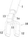
图2显示图1所示的电缆1、与电缆1连接的第一电连接端子10和与第一电连接端子10对配的对配端子30的立体示意图;图3显示图2所示的电缆1和电连接端子10的立体示意图;图4显示图1所示的汇流条20和与汇流条20连接的第二电连接端子20的立体示意图。FIG. 2 shows a perspective view of the
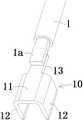
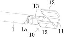
如图1至图4所示,在图示的实施例中,第一电连接端子10包括第一基部11和多个第一插片12。多个第一插片12连接到第一基部11上并彼此间隔开。As shown in FIGS. 1 to 4 , in the illustrated embodiment, the first
如图1至图4所示,在图示的实施例中,第二电连接端子20,包括第二基部21和多个第二插片22。多个第二插片22连接到第二基部21上并彼此间隔开。As shown in FIGS. 1 to 4 , in the illustrated embodiment, the second
如图1至图4所示,在图示的实施例中,每个对配端子30包括与第一插片12对配的第一对配端31和与第二插片22对配的第二对配端32。第一电连接端子10的每个第一插片12适于以插拔的方式与对配端子30的第一对配端31对配。第二电连接端子20的每个第二插片22适于以插拔的方式与对配端子30的第二对配端32对配。在图示的实施例中,每个对配端子30呈H型,每个对配端子30的第一对配端31包括一对第一弹性夹持臂,第一插片12适于插入到一对第一弹性夹持臂之间并被夹持在一对第一弹性夹持臂之间。类似地,每个对配端子30的第二对配端32包括一对第二弹性夹持臂,第二插片22适于插入到一对第二弹性夹持臂之间并被夹持在一对第二弹性夹持臂之间。As shown in FIGS. 1 to 4 , in the illustrated embodiment, each
如图1至图4所示,在图示的实施例中,第一电连接端子10包括并排布置的两个第一插片12,两个第一插片12分别连接到第一基部11的宽度方向的两侧并与第一基部11的宽度方向垂直。在图示的实施例中,两个第一插片12沿第一基部11的厚度方向朝下延伸,以适于与两个对配端子30同时对配。As shown in FIGS. 1 to 4 , in the illustrated embodiment, the first
在图1-4所示的实施例中,第一电连接端子10采用了两个并联的第一插片12,因此减小了第一电连接端子10的长度和电流流经的路径,而且电流在分流后流经的路径更短,因此,本发明的第一电连接端子10的体电阻较低,发热更小,更适应大电流应用。In the embodiment shown in FIGS. 1-4 , the first
此外,在图1-4所示的实施例中,两个并排布置的第一插片12增加了第一电连接端子10的横截面积和表面面积,从而提高了第一电连接端子10的等效电流截面积和有效散热面积,使得第一电连接端子10更适应大电流应用。In addition, in the embodiment shown in FIGS. 1-4 , the two side-by-side first inserts 12 increase the cross-sectional area and surface area of the first
如图1至图4所示,在图示的实施例中,第二电连接端子20包括两个第二插片22,两个第二插片22分别连接到第二基部21的宽度方向的两侧,使得第二电连接端子20呈U型。两个第二插片22沿第二基部21的厚度方向朝上延伸,以适于与两个对配端子30同时对配。As shown in FIGS. 1 to 4 , in the illustrated embodiment, the second
在图1-4所示的实施例中,第二电连接端子20采用了两个并联的第二插片22,因此减小了第二电连接端子20的长度和电流流经的路径,而且电流在分流后流经的路径更短,因此,本发明的第二电连接端子20的体电阻较低,发热更小,更适应大电流应用。In the embodiment shown in FIGS. 1-4 , the second
此外,在图1-4所示的实施例中,两个并排布置的第二插片22增加了第二电连接端子20的横截面积和表面面积,从而提高了第二电连接端子20的等效电流截面积和有效散热面积,使得第二电连接端子20更适应大电流应用。In addition, in the embodiment shown in FIGS. 1-4 , the two side-by-side second inserts 22 increase the cross-sectional area and surface area of the second
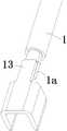
如图1至图4所示,在图示的实施例中,第一电连接端子10还包括连接部13,连接部13与第一基部11连接。连接部13呈平板状,并且电缆1的端部1a被预先加工成扁平状。电缆1的扁平状的端部1a被焊接到平板状的连接部13上。电缆1的端部1a的连接表面可以被焊接到连接部13的上表面或下表面上。As shown in FIGS. 1 to 4 , in the illustrated embodiment, the first
如图1至图4所示,在图示的实施例中,连接部13的宽度大于第一基部11的宽度,但是,本发明不局限于此,连接部13的宽度也可以等于或小于第一基部11的宽度。As shown in FIGS. 1 to 4 , in the illustrated embodiment, the width of the connecting
如图1至图4所示,在图示的实施例中,连接部13的延伸方向与第一基部11的长度方向平行。即,连接部13的延伸方向与电缆1的轴向平行。As shown in FIGS. 1 to 4 , in the illustrated embodiment, the extending direction of the connecting
如图1至图4所示,在图示的实施例中,汇流条2与第二电连接端子20的第二基部21电连接。第二电连接端子20的第二基部21以焊接、铆接或螺纹连接的方式被电连接到汇流条2上。As shown in FIGS. 1 to 4 , in the illustrated embodiment, the
图5显示根据本发明的另一个实例性的实施例的电缆1和与电缆1连接的第一电连接端子10的立体示意图。5 shows a schematic perspective view of a
与图1-4所示的实施例相比,图5所示的实施例的区别主要在于第一电连接端子10的连接部13的尺寸和电缆1的焊接位置不同。Compared with the embodiment shown in FIGS. 1-4 , the difference between the embodiment shown in FIG. 5 is mainly that the size of the connecting
在图5所示的实施例中,第一电连接端子10的连接部13呈平板状,并且连接部13的宽度小于第一基部11的宽度。电缆1的端部1a呈扁平状并焊接到平板状的连接部13的上表面上。In the embodiment shown in FIG. 5 , the connecting
图6显示根据本发明的另一个实例性的实施例的电缆1和与电缆1连接的第一电连接端子10的立体示意图。6 shows a schematic perspective view of a
与图5所示的实施例相比,图6所示的实施例的区别主要在于电缆1的焊接位置不同。在图5所示的实施例中,电缆1的端部1a焊接到平板状的连接部13的下表面上。Compared with the embodiment shown in FIG. 5 , the difference between the embodiment shown in FIG. 6 is mainly that the welding position of the
图7显示根据本发明的另一个实例性的实施例的电缆1和与电缆1连接的第一电连接端子10的立体示意图。FIG. 7 shows a schematic perspective view of a
与图5所示的实施例相比,图7所示的实施例的区别主要在于取消了第一电连接端子10的连接部13。在图7所示的实施例中,第一电连接端子10没有连接部13,电缆1的端部1a直接焊接到第一电连接端子10的第一基部11的上表面或下表面上。Compared with the embodiment shown in FIG. 5 , the main difference between the embodiment shown in FIG. 7 is that the
图8显示根据本发明的另一个实例性的实施例的电缆1和与电缆1连接的第一电连接端子10的立体示意图。FIG. 8 shows a schematic perspective view of a
与图5所示的实施例相比,图8所示的实施例的区别主要在于第一电连接端子10的连接部13的结构不同。在图8所示的实施例中,第一电连接端子10的连接部13呈侧翼状,包括一对侧翼。电缆1的端部1a呈扁平状。连接部13的一对侧翼被压接到电缆1的端部1a上。Compared with the embodiment shown in FIG. 5 , the difference between the embodiment shown in FIG. 8 is mainly that the structure of the
图9显示根据本发明的另一个实例性的实施例的电缆1和与电缆1连接的第一电连接端子10的立体示意图。FIG. 9 shows a schematic perspective view of a
与图5所示的实施例相比,图9所示的实施例的区别主要在于第一电连接端子10的连接部13的结构不同。在图9所示的实施例中,第一电连接端子10的连接部13呈圆筒状。电缆1的端部1a呈圆柱状并插入圆筒状的连接部13中。圆筒状的连接部13被压接到电缆1的端部1a上。Compared with the embodiment shown in FIG. 5 , the difference between the embodiment shown in FIG. 9 is mainly that the structure of the
图10显示根据本发明的另一个实例性的实施例的电缆1和与电缆1连接的第一电连接端子10的立体示意图。FIG. 10 shows a schematic perspective view of a
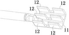
与图9所示的实施例相比,图10所示的实施例的区别主要在于第一电连接端子10上的第一插片11的数量不同。在图1至图9所示的实施例中,第一电连接端子10包括并排布置的两个第一插片11,但是在图10所示的实施例中,第一电连接端子10包括并排布置的三个第一插片11。Compared with the embodiment shown in FIG. 9 , the difference between the embodiment shown in FIG. 10 is mainly that the number of the
在图10所示的实施例中,第一电连接端子10包括三个第一插片12。三个第一插片12并排设置并与第一基部11的宽度方向垂直。三个第一插片12中的两个分别连接到第一基部11的宽度方向的两侧,剩余的一个第一插片12连接到第一基部11的宽度方向的中间部位。In the embodiment shown in FIG. 10 , the first
图11显示根据本发明的另一个实例性的实施例的电缆1和与电缆1连接的第一电连接端子10的立体示意图。FIG. 11 shows a schematic perspective view of a
与图10所示的实施例相比,图11所示的实施例的区别主要在于第一电连接端子10的连接部13的结构不同。在图11所示的实施例中,第一电连接端子10包括三个第一插片12,三个第一插片12中的两个并排设置并与第一基部11的宽度方向垂直,三个第一插片12中剩余的一个的插片12被设置成与第一基部11的长度方向垂直。Compared with the embodiment shown in FIG. 10 , the difference between the embodiment shown in FIG. 11 is mainly that the structure of the
在图11所示的实施例中,三个第一插片12中的两个分别连接到第一基部11的宽度方向的两侧,三个第一插片12中剩余的一个的插片12连接到第一基部11的长度方向的一端。In the embodiment shown in FIG. 11 , two of the three
图12显示根据本发明的另一个实例性的实施例的电缆1和与电缆1连接的第一电连接端子10的立体示意图。FIG. 12 shows a schematic perspective view of a
与图10所示的实施例相比,图12所示的实施例的区别主要在于第一电连接端子10的连接部13的结构不同。在图12所示的实施例中,第一电连接端子10包括六个第一插片12,并且六个第一插片12沿第一基部11的宽度方向和长度方向布置成2行3列。Compared with the embodiment shown in FIG. 10 , the difference between the embodiment shown in FIG. 12 is mainly that the structure of the
需要说明的是,第一电连接端子10上的第一插片12的数量和布置不局限于图示的实施例,例如,第一电连接端子10上的第一插片12的数量可以为四个、五个、七个或更多个,并且多个第一插片12也可以采用纵横交错布置。It should be noted that the number and arrangement of the
图13显示根据本发明的另一个实例性的实施例的电缆1和与电缆1连接的第一电连接端子10的立体示意图。FIG. 13 shows a schematic perspective view of a
与图5所示的实施例相比,图13所示的实施例的区别主要在于第一电连接端子10的连接部13的延伸方向不同。在图5所示的实施例中,第一电连接端子10的连接部13的延伸方向与第一基部11的长度方向平行。但是,在图13所示的实施例中,第一电连接端子10的连接部13被相对于第一基部11弯折大约90度,使得第一电连接端子10的连接部13的延伸方向与第一基部11的长度方向成大约90度的夹角。请注意,本发明不局限于图示的实施例,例如,第一电连接端子10的连接部13的延伸方向可以根据实际需要改变,例如,第一电连接端子10的连接部13的延伸方向与第一基部11的长度方向可以成10度、20度或30度等合适的夹角。Compared with the embodiment shown in FIG. 5 , the main difference between the embodiment shown in FIG. 13 is that the extension direction of the
图14显示根据本发明的另一个实例性的实施例的电缆1和与电缆1连接的第一电连接端子10的立体示意图。FIG. 14 shows a schematic perspective view of the
与图5所示的实施例相比,图14所示的实施例的区别主要在于电缆1的形状不同。在图5所示的实施例中,电缆1为普通的圆形电缆。在图14所示的实施例中,电缆1为扁平电缆,因此,扁平的电缆1的端部可以直接焊接到第一电连接端子10的连接部13上,无需预先加工成扁平状。Compared with the embodiment shown in FIG. 5 , the embodiment shown in FIG. 14 differs mainly in the shape of the
尽管未图示,在本发明的另一个实例性的实施例中,还公开一种电连接器,该电连接器包括壳体和容纳在该壳体中的第一电连接端子10。Although not shown, in another exemplary embodiment of the present invention, an electrical connector is also disclosed, which includes a housing and a first
本领域的技术人员可以理解,上面所描述的实施例都是示例性的,并且本领域的技术人员可以对其进行改进,各种实施例中所描述的结构在不发生结构或者原理方面的冲突的情况下可以进行自由组合,这些变化理应落入本发明的保护范围以内。Those skilled in the art can understand that the above-described embodiments are all exemplary, and those skilled in the art can make improvements thereto, and the structures described in the various embodiments do not conflict in terms of structures or principles It can be freely combined under the circumstance that these changes should fall within the protection scope of the present invention.
虽然结合附图对本发明进行了说明,但是附图中公开的实施例旨在对本发明优选实施方式进行示例性说明,而不能理解为对本发明的一种限制。Although the present invention has been described with reference to the accompanying drawings, the embodiments disclosed in the accompanying drawings are intended to illustrate the preferred embodiments of the present invention and should not be construed as a limitation of the present invention.
虽然本发明的总体构思的一些实施例已被显示和说明,本领域普通技术人员将理解,在不背离本发明的总体构思的原则和精神的情况下,可对这些实施例做出改变,本发明的范围以权利要求和它们的等同物限定。Although some embodiments of the present general inventive concept have been shown and described, those of ordinary skill in the art will appreciate that changes may be made to these embodiments without departing from the principles and spirit of the present general inventive concept. The scope of the invention is defined by the claims and their equivalents.
应注意,措词“包括”不排除其它元件或步骤,措词“一”或“一个”不排除多个。另外,权利要求的任何元件标号不应理解为限制本发明的范围。It should be noted that the word "comprising" does not exclude other elements or steps, and the word "a" or "an" does not exclude a plurality. Furthermore, any element numbers in the claims should not be construed as limiting the scope of the invention.
Claims (19)
Translated fromChinesePriority Applications (4)
| Application Number | Priority Date | Filing Date | Title |
|---|---|---|---|
| CN202110402459.4ACN115224514A (en) | 2021-04-14 | 2021-04-14 | Electrical connection terminal and electrical connection assembly |
| DE102022108455.8ADE102022108455A1 (en) | 2021-04-14 | 2022-04-07 | ELECTRICAL TERMINAL AND ELECTRICAL CONNECTION ASSEMBLY |
| US17/717,198US12034240B2 (en) | 2021-04-14 | 2022-04-11 | Electrical connection terminal and electrical connection assembly |
| KR1020220044992AKR20220142368A (en) | 2021-04-14 | 2022-04-12 | Electrical connection terminal and electrical connection assembly |
Applications Claiming Priority (1)
| Application Number | Priority Date | Filing Date | Title |
|---|---|---|---|
| CN202110402459.4ACN115224514A (en) | 2021-04-14 | 2021-04-14 | Electrical connection terminal and electrical connection assembly |
Publications (1)
| Publication Number | Publication Date |
|---|---|
| CN115224514Atrue CN115224514A (en) | 2022-10-21 |
Family
ID=83447196
Family Applications (1)
| Application Number | Title | Priority Date | Filing Date |
|---|---|---|---|
| CN202110402459.4APendingCN115224514A (en) | 2021-04-14 | 2021-04-14 | Electrical connection terminal and electrical connection assembly |
Country Status (4)
| Country | Link |
|---|---|
| US (1) | US12034240B2 (en) |
| KR (1) | KR20220142368A (en) |
| CN (1) | CN115224514A (en) |
| DE (1) | DE102022108455A1 (en) |
Citations (8)
| Publication number | Priority date | Publication date | Assignee | Title |
|---|---|---|---|---|
| US20020025732A1 (en)* | 2000-08-30 | 2002-02-28 | Hsieh Shao C. | Electrical connector |
| CN201178160Y (en)* | 2008-03-14 | 2009-01-07 | 正淩精密工业股份有限公司 | Power Terminal Structure |
| CN103262357A (en)* | 2010-12-17 | 2013-08-21 | 泰科电子公司 | Power connector assembly |
| CN105474471A (en)* | 2013-08-19 | 2016-04-06 | 富加宜(亚洲)私人有限公司 | Electrical connectors with high retention force |
| CN106785570A (en)* | 2017-01-09 | 2017-05-31 | 深圳尼索科连接技术有限公司 | Plug bush type Electical connector |
| CN208062297U (en)* | 2018-04-09 | 2018-11-06 | 安费诺商用电子产品(成都)有限公司 | A kind of IDC connector terminal and IDC connector |
| US20210005997A1 (en)* | 2019-07-03 | 2021-01-07 | Dinkle Enterprise Co., Ltd. | Connector for high-current terminal |
| CN215497176U (en)* | 2021-04-14 | 2022-01-11 | 泰科电子(上海)有限公司 | Electrical connection terminal and electrical connection assembly |
Family Cites Families (14)
| Publication number | Priority date | Publication date | Assignee | Title |
|---|---|---|---|---|
| US5588884A (en)* | 1995-09-08 | 1996-12-31 | Packard Hughes Interconnect Company | Stamped and formed contacts for a power connector |
| US5957734A (en)* | 1998-01-21 | 1999-09-28 | General Motors Corporation | Tuning fork inline connection system |
| US6302709B1 (en)* | 2000-06-05 | 2001-10-16 | Power-One, Inc. | Multiple function high current interconnect with integrated bus bar |
| US6685514B2 (en)* | 2002-04-05 | 2004-02-03 | Larry J. Costa | Folding blade electrical terminal |
| JP4551166B2 (en)* | 2004-09-13 | 2010-09-22 | 矢崎総業株式会社 | Device direct connector |
| JP5723695B2 (en)* | 2011-06-21 | 2015-05-27 | 矢崎総業株式会社 | Female terminal |
| US9190756B2 (en)* | 2013-08-01 | 2015-11-17 | Lear Corporation | Electrical terminal assembly |
| CN203456624U (en)* | 2013-09-27 | 2014-02-26 | 泰科电子(上海)有限公司 | Connection terminal |
| ES2820375T3 (en)* | 2015-02-27 | 2021-04-20 | Byrne Norman R | Electrical Contact Receptacle for Busbars and Blade Terminals |
| US9692163B1 (en)* | 2016-08-30 | 2017-06-27 | Te Connectivity Corporation | Crush rib housing for postive lock receptacle |
| DE102016221351A1 (en)* | 2016-10-28 | 2018-05-03 | Te Connectivity Germany Gmbh | Flat contact socket with extension arm |
| JP6820290B2 (en)* | 2018-06-11 | 2021-01-27 | 矢崎総業株式会社 | Connection terminal and terminal connection structure |
| CN212874843U (en)* | 2020-08-31 | 2021-04-02 | 安费诺商用电子产品(成都)有限公司 | Electrical connector |
| JP7541282B2 (en)* | 2021-01-25 | 2024-08-28 | 住友電装株式会社 | connector |
- 2021
- 2021-04-14CNCN202110402459.4Apatent/CN115224514A/enactivePending
- 2022
- 2022-04-07DEDE102022108455.8Apatent/DE102022108455A1/enactivePending
- 2022-04-11USUS17/717,198patent/US12034240B2/enactiveActive
- 2022-04-12KRKR1020220044992Apatent/KR20220142368A/enactivePending
Patent Citations (8)
| Publication number | Priority date | Publication date | Assignee | Title |
|---|---|---|---|---|
| US20020025732A1 (en)* | 2000-08-30 | 2002-02-28 | Hsieh Shao C. | Electrical connector |
| CN201178160Y (en)* | 2008-03-14 | 2009-01-07 | 正淩精密工业股份有限公司 | Power Terminal Structure |
| CN103262357A (en)* | 2010-12-17 | 2013-08-21 | 泰科电子公司 | Power connector assembly |
| CN105474471A (en)* | 2013-08-19 | 2016-04-06 | 富加宜(亚洲)私人有限公司 | Electrical connectors with high retention force |
| CN106785570A (en)* | 2017-01-09 | 2017-05-31 | 深圳尼索科连接技术有限公司 | Plug bush type Electical connector |
| CN208062297U (en)* | 2018-04-09 | 2018-11-06 | 安费诺商用电子产品(成都)有限公司 | A kind of IDC connector terminal and IDC connector |
| US20210005997A1 (en)* | 2019-07-03 | 2021-01-07 | Dinkle Enterprise Co., Ltd. | Connector for high-current terminal |
| CN215497176U (en)* | 2021-04-14 | 2022-01-11 | 泰科电子(上海)有限公司 | Electrical connection terminal and electrical connection assembly |
Also Published As
| Publication number | Publication date |
|---|---|
| KR20220142368A (en) | 2022-10-21 |
| US20220336987A1 (en) | 2022-10-20 |
| DE102022108455A1 (en) | 2022-10-20 |
| US12034240B2 (en) | 2024-07-09 |
Similar Documents
| Publication | Publication Date | Title |
|---|---|---|
| CN110011100B (en) | Rectangular reed jack terminal of electric connector | |
| CN202772303U (en) | Electrical connector and electrical connector assembly | |
| US9337466B2 (en) | Power terminal connector | |
| CN104321906A (en) | Bimetal buss bar assembly | |
| CN115051178B (en) | Current transmission components and current transmission systems | |
| CN114465032A (en) | Electrical connector assembly | |
| CN112928512B (en) | Electrical connector | |
| CN215497176U (en) | Electrical connection terminal and electrical connection assembly | |
| CN217215185U (en) | A plug-in terminal and a plug-in terminal installation structure | |
| CN109935988B (en) | Electric connector and electric connector assembly | |
| KR102215911B1 (en) | Power terminal connector | |
| CN115224514A (en) | Electrical connection terminal and electrical connection assembly | |
| JP5112502B2 (en) | connector | |
| CN114498130A (en) | Connector with a locking member | |
| CN109119780B (en) | A conductive contact structure and electrical connector | |
| CN219677603U (en) | Connector and conductive structure thereof | |
| CN106785570A (en) | Plug bush type Electical connector | |
| CN218975838U (en) | Conductive terminal assemblies and electrical connectors | |
| CN111082240A (en) | Conductive connection structure of charging plug, charging plug and charging terminal | |
| CN114284773B (en) | Connector with a plurality of connectors | |
| CN214542580U (en) | Current transmission assembly and current transmission system | |
| CN215119299U (en) | Connector | |
| CN106384901B (en) | Automobile laser welding terminal | |
| CN223141090U (en) | A chip contact | |
| CN222395068U (en) | Connecting terminals and connectors |
Legal Events
| Date | Code | Title | Description |
|---|---|---|---|
| PB01 | Publication | ||
| PB01 | Publication | ||
| SE01 | Entry into force of request for substantive examination | ||
| SE01 | Entry into force of request for substantive examination |