CN115219791A - Harmonic impedance scanning method - Google Patents
Harmonic impedance scanning methodDownload PDFInfo
- Publication number
- CN115219791A CN115219791ACN202210681015.3ACN202210681015ACN115219791ACN 115219791 ACN115219791 ACN 115219791ACN 202210681015 ACN202210681015 ACN 202210681015ACN 115219791 ACN115219791 ACN 115219791A
- Authority
- CN
- China
- Prior art keywords
- harmonic
- value
- scanning
- phase difference
- transmission system
- Prior art date
- Legal status (The legal status is an assumption and is not a legal conclusion. Google has not performed a legal analysis and makes no representation as to the accuracy of the status listed.)
- Pending
Links
Images


Classifications
- G—PHYSICS
- G01—MEASURING; TESTING
- G01R—MEASURING ELECTRIC VARIABLES; MEASURING MAGNETIC VARIABLES
- G01R27/00—Arrangements for measuring resistance, reactance, impedance, or electric characteristics derived therefrom
- G01R27/02—Measuring real or complex resistance, reactance, impedance, or other two-pole characteristics derived therefrom, e.g. time constant
- G01R27/08—Measuring resistance by measuring both voltage and current
Landscapes
- Physics & Mathematics (AREA)
- General Physics & Mathematics (AREA)
- Measurement Of Resistance Or Impedance (AREA)
Abstract
Description
Translated fromChinese技术领域technical field
本申请涉及电力系统技术领域,特别是涉及一种谐波阻抗扫描方法、装置、计算机设备、存储介质和计算机程序产品。The present application relates to the technical field of power systems, and in particular, to a harmonic impedance scanning method, device, computer equipment, storage medium and computer program product.
背景技术Background technique
近年来,随着电力系统的快速发展,目前的超高压和特高压直流输电一般采用传统直流技术,其换流器会有大量特征谐波,需要配置一定数量的滤波器用于抑制谐波,但不当的滤波器设计或直流系统运行方式可能会引发直流系统谐振,甚至引发交直流系统谐波不稳定。确定HVDC(High Voltage Direct Current,高压直流输电)系统的谐波阻抗特性是研究交直流谐波谐振问题的关键。目前,用于确定高压直流输电系统谐波阻抗特性的方法主要是利用测试信号法(又称小信号测试法,或频率扫描法);测试信号法通过逐次向高压直流输电系统注入不同频率的谐波源,并测量高压直流输电系统的响应的方式,从而扫描得到高压直流输电系统的谐波阻抗值。但是这种谐波阻抗扫描方法操作过程繁琐,扫描效率低。In recent years, with the rapid development of the power system, the current ultra-high voltage and ultra-high voltage DC transmission generally adopts traditional DC technology, and its converters have a large number of characteristic harmonics, and a certain number of filters need to be configured to suppress harmonics. Improper filter design or operation mode of DC system may cause resonance of DC system, and even lead to harmonic instability of AC and DC system. Determining the harmonic impedance characteristics of HVDC (High Voltage Direct Current, high voltage direct current transmission) system is the key to study the problem of AC and DC harmonic resonance. At present, the method used to determine the harmonic impedance characteristics of the HVDC transmission system mainly uses the test signal method (also known as the small signal test method, or the frequency sweep method); The wave source is measured, and the response of the HVDC transmission system is measured, so as to obtain the harmonic impedance value of the HVDC transmission system by scanning. However, this harmonic impedance scanning method has a complicated operation process and low scanning efficiency.
因此,如何提高高压直流输电系统谐波阻抗扫描的扫描效率,是本领域技术人员目前需要解决的技术问题。Therefore, how to improve the scanning efficiency of the harmonic impedance scanning of the HVDC transmission system is a technical problem that needs to be solved by those skilled in the art.
发明内容SUMMARY OF THE INVENTION
基于此,有必要针对上述技术问题,提供一种能够高效便捷地对高压直流输电系统进行谐波阻抗扫描的谐波阻抗扫描方法、装置、计算机设备、计算机可读存储介质和计算机程序产品。Based on this, it is necessary to provide a harmonic impedance scanning method, device, computer equipment, computer-readable storage medium and computer program product that can efficiently and conveniently perform harmonic impedance scanning of a high-voltage direct current transmission system.
第一方面,本申请提供了一种谐波阻抗扫描方法,所述方法包括:In a first aspect, the present application provides a harmonic impedance scanning method, the method comprising:
获取谐波频率参数;Get harmonic frequency parameters;
依据所述谐波频率参数,生成不同扫描频率的谐波源信号;generating harmonic source signals of different scanning frequencies according to the harmonic frequency parameters;
将所述不同扫描频率的谐波源信号同时注入至高压直流输电系统中,并采集所述高压直流输电系统的电信号值;injecting the harmonic source signals of different scanning frequencies into the HVDC transmission system at the same time, and collecting the electrical signal value of the HVDC transmission system;
根据所述电信号值,确定所述高压直流输电系统与各所述谐波源信号对应的谐波阻抗值。According to the electrical signal value, the harmonic impedance value corresponding to each of the harmonic source signals of the HVDC transmission system is determined.
在其中一个实施例中,所述谐波频率参数包括初始扫描频率和扫描频率间隔;所述依据所述谐波频率参数,生成不同扫描频率的谐波源信号包括:In one embodiment, the harmonic frequency parameters include an initial sweep frequency and a sweep frequency interval; and the generating harmonic source signals with different sweep frequencies according to the harmonic frequency parameters includes:
根据所述初始扫描频率和所述扫描频率间隔,确定预设数量个扫描频率;Determine a preset number of scan frequencies according to the initial scan frequency and the scan frequency interval;
获取待生成谐波源信号的初始相位和相位差值;Obtain the initial phase and phase difference value of the harmonic source signal to be generated;
根据所述初始相位和所述相位差值,确定与各所述扫描频率对应的目标初始相位值;determining a target initial phase value corresponding to each of the scanning frequencies according to the initial phase and the phase difference value;
依据各所述扫描频率和各所述目标初始相位值,生成不同扫描频率的谐波源信号。According to each of the scan frequencies and each of the target initial phase values, harmonic source signals of different scan frequencies are generated.
在其中一个实施例中,所述相位差值包括多种不同的相位差值;In one of the embodiments, the phase difference value includes a plurality of different phase difference values;
所述依据各所述扫描频率和各所述目标初始相位值,生成不同扫描频率的谐波源信号目标初始相位值,包括:The generating target initial phase values of harmonic source signals of different scanning frequencies according to each of the scanning frequencies and each of the target initial phase values, including:
针对每种所述相位差值,依据各所述扫描频率和各所述目标初始相位值,生成不同扫描频率的谐波源信号目标初始相位值。For each of the phase difference values, according to each of the scan frequencies and each of the target initial phase values, target initial phase values of harmonic source signals of different scan frequencies are generated.
在其中一个实施例中,所述方法还包括:In one embodiment, the method further includes:
统计相同相位差值对应的谐波源信号的谐波源总幅值;Count the total amplitude of the harmonic source of the harmonic source signal corresponding to the same phase difference value;
确定所述谐波总幅值的最小值,并将所述谐波源总幅值的最小值对应的相位差值确定目标相位差值;determining the minimum value of the total harmonic amplitude value, and determining the target phase difference value corresponding to the phase difference value corresponding to the minimum value of the total harmonic amplitude value of the harmonic source;
所述根据所述初始相位和所述相位差值,确定与各所述扫描频率对应的目标初始相位值目标初始相位值,包括:The determining a target initial phase value corresponding to each scanning frequency according to the initial phase and the phase difference value includes:
根据所述初始相位和所述目标相位差值,确定与各所述扫描频率对应的目标初始相位值。According to the difference between the initial phase and the target phase, a target initial phase value corresponding to each of the scanning frequencies is determined.
在其中一个实施例中,所述方法还包括:In one embodiment, the method further includes:
确定所述谐波源总幅值是否小于预设幅值阈值;determining whether the total amplitude of the harmonic source is less than a preset amplitude threshold;
若所述谐波源总幅值小于所述预设幅值阈值,则进入所述确定所述谐波总幅值的最小值,并将所述谐波源总幅值的最小值对应的相位差值确定目标相位差值的步骤;If the total amplitude of the harmonic source is less than the preset amplitude threshold, enter the process of determining the minimum value of the total harmonic amplitude, and set the phase corresponding to the minimum total amplitude of the harmonic source The step of determining the target phase difference value by the difference value;
若否,生成提示信息;所述提示信息用于提示所述谐波源总幅值异常。If not, generate prompt information; the prompt information is used to prompt that the total amplitude of the harmonic source is abnormal.
在其中一个实施例中,所述谐波源信号包括谐波电压源信号和谐波电流源信号。In one of the embodiments, the harmonic source signal includes a harmonic voltage source signal and a harmonic current source signal.
第二方面,本申请还提供了一种谐波阻抗扫描装置,所述装置包括:In a second aspect, the present application also provides a harmonic impedance scanning device, the device comprising:
获取模块,用于获取谐波频率参数;The acquisition module is used to acquire harmonic frequency parameters;
第一确定模块,用于依据所述谐波频率参数,生成不同扫描频率的谐波源信号;a first determining module, configured to generate harmonic source signals of different scanning frequencies according to the harmonic frequency parameters;
输入模块,用于将所述不同扫描频率的谐波源信号同时注入至高压直流输电系统中,并采集所述高压直流输电系统的电信号值;an input module for simultaneously injecting the harmonic source signals of different scanning frequencies into the high-voltage direct current transmission system, and collecting the electrical signal value of the high-voltage direct current transmission system;
第二确定模块,用于根据所述电信号值,确定所述高压直流输电系统与各所述谐波源信号对应的谐波阻抗值。The second determination module is configured to determine, according to the electrical signal value, the harmonic impedance value corresponding to each of the harmonic source signals of the HVDC transmission system.
第三方面,本申请还提供了一种计算机设备。所述计算机设备包括存储器和处理器,所述存储器存储有计算机程序,所述处理器执行所述计算机程序时实现如上方法的步骤。In a third aspect, the present application also provides a computer device. The computer device includes a memory and a processor, the memory stores a computer program, and the processor implements the steps of the above method when executing the computer program.
第四方面,本申请还提供了一种计算机可读存储介质。所述计算机可读存储介质,其上存储有计算机程序,所述计算机程序被处理器执行时实现如上方法的步骤。In a fourth aspect, the present application also provides a computer-readable storage medium. The computer-readable storage medium has a computer program stored thereon, and when the computer program is executed by a processor, implements the steps of the above method.
第五方面,本申请还提供了一种计算机程序产品。所述计算机程序产品,包括计算机程序,该计算机程序被处理器执行时实现如上方法的步骤。In a fifth aspect, the present application also provides a computer program product. The computer program product includes a computer program that, when executed by a processor, implements the steps of the above method.
上述谐波阻抗扫描方法、装置、计算机设备、存储介质和计算机程序产品,本方案中,在获取谐波频率参数后,依据所述谐波频率参数生成不同扫描频率的谐波源信号,然后将所述不同扫描频率的谐波源信号同时注入至高压直流输电系统中,并采集所述高压直流输电系统的电信号值;根据电信号值,确定高压直流输电系统与各谐波源信号分别对应的谐波阻抗值;通过采集同时注入高压直流输电系统中的不同扫描频率的谐波源信号对应的电信号值,避免需要针对各谐波源信号分别采集对应的电信号值;再依据采集到的电信号值确定高压直流输电系统中与各谐波源信号分别对应的谐波阻抗值,能够根据单次采集的电信号值批量确定出不同谐波源信号对应的谐波阻抗值,因此本方案能高效便捷地对高压直流输电系统进行谐波阻抗扫描。The above harmonic impedance scanning method, device, computer equipment, storage medium and computer program product, in this solution, after obtaining harmonic frequency parameters, according to the harmonic frequency parameters, the harmonic source signals of different scanning frequencies are generated, and then the harmonic source signals of different scanning frequencies are generated. The harmonic source signals of different scanning frequencies are simultaneously injected into the HVDC transmission system, and the electrical signal values of the HVDC transmission system are collected; according to the electrical signal values, it is determined that the HVDC transmission system corresponds to each harmonic source signal respectively By collecting the electrical signal values corresponding to the harmonic source signals of different scanning frequencies injected into the HVDC transmission system at the same time, it avoids the need to collect the corresponding electrical signal values for each harmonic source signal separately; The electrical signal value of the HVDC transmission system determines the harmonic impedance value corresponding to each harmonic source signal in the HVDC transmission system, and the harmonic impedance value corresponding to different harmonic source signals can be determined in batches according to the electrical signal value collected for a single time. The scheme can efficiently and conveniently perform harmonic impedance scanning of HVDC transmission system.
附图说明Description of drawings
图1为一个实施例中谐波阻抗扫描方法的流程示意图;1 is a schematic flowchart of a harmonic impedance scanning method in one embodiment;
图2为一个实施例中依据谐波频率参数,生成不同扫描频率的谐波源信号步骤的流程示意图;2 is a schematic flowchart of steps of generating harmonic source signals of different scanning frequencies according to harmonic frequency parameters in one embodiment;
图3为一个实施例中直流换流器交、直流等值阻抗结构示意图;3 is a schematic diagram of the structure of the AC and DC equivalent impedances of the DC converter in one embodiment;
图4为另一个实施例中谐波阻抗扫描方法的流程示意图;4 is a schematic flowchart of a harmonic impedance scanning method in another embodiment;
图5为一个实施例中谐波阻抗扫描装置的结构框图;5 is a structural block diagram of a harmonic impedance scanning device in one embodiment;
图6为一个实施例中计算机设备的内部结构图。FIG. 6 is a diagram of the internal structure of a computer device in one embodiment.
具体实施方式Detailed ways
为了使本申请的目的、技术方案及优点更加清楚明白,以下结合附图及实施例,对本申请进行进一步详细说明。应当理解,此处描述的具体实施例仅仅用以解释本申请,并不用于限定本申请。In order to make the purpose, technical solutions and advantages of the present application more clearly understood, the present application will be described in further detail below with reference to the accompanying drawings and embodiments. It should be understood that the specific embodiments described herein are only used to explain the present application, but not to limit the present application.
本申请实施例提供的一种谐波阻抗扫描方法,可以应用于终端中,终端获取谐波频率参数;依据谐波频率参数,生成不同扫描频率的谐波源信号;将不同扫描频率的谐波源信号同时注入至高压直流输电系统中,并采集高压直流输电系统的电信号值;根据电信号值,确定高压直流输电系统与各谐波源信号对应的谐波阻抗值。终端可以但不限于是各种个人计算机、笔记本电脑、智能手机、平板电脑。The harmonic impedance scanning method provided by the embodiment of the present application can be applied to a terminal, where the terminal obtains harmonic frequency parameters; generates harmonic source signals of different scanning frequencies according to the harmonic frequency parameters; The source signal is injected into the HVDC transmission system at the same time, and the electrical signal value of the HVDC transmission system is collected; according to the electrical signal value, the harmonic impedance value corresponding to the HVDC transmission system and each harmonic source signal is determined. The terminal can be, but is not limited to, various personal computers, notebook computers, smart phones, and tablet computers.
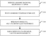
在一个实施例中,如图1所示,提供了一种谐波阻抗扫描方法,本实施例以该方法应用于终端进行举例说明,本实施例中,该方法包括以下步骤:In one embodiment, as shown in FIG. 1 , a harmonic impedance scanning method is provided. In this embodiment, the method is applied to a terminal for illustration. In this embodiment, the method includes the following steps:
S200:获取谐波频率参数。S200: Obtain harmonic frequency parameters.
具体的,谐波频率参数可以是用于确定出扫描频率的参数;谐波频率参数可以包括扫描频率的最大值、扫描频率的最小值和扫描频率间隔;谐波频率参数也可以是扫描频率。Specifically, the harmonic frequency parameter may be a parameter for determining the scanning frequency; the harmonic frequency parameter may include the maximum value of the scanning frequency, the minimum value of the scanning frequency and the scanning frequency interval; the harmonic frequency parameter may also be the scanning frequency.
在实际操作中,可以通过响应于用户的输入操作获取谐波频率参数,也可以是从指定存储位置读取预先存储的谐波频率参数,本实施例对获取谐波频率参数的具体方式不做限定。In actual operation, the harmonic frequency parameters can be obtained by responding to the user's input operation, or the pre-stored harmonic frequency parameters can be read from a designated storage location. The specific method of obtaining the harmonic frequency parameters is not described in this embodiment. limited.
S400:依据谐波频率参数,生成不同扫描频率的谐波源信号。S400: Generate harmonic source signals of different scanning frequencies according to the harmonic frequency parameters.
其中,谐波源信号指的是在基于测试信号法对高压直流输电系统进行谐波阻抗扫描时,注入至高压直流输电系统中的测试信号。本实施例中,在获取到谐波频率参数后,确定出预设数量的不同扫描频率;针对各不同的扫描频率,分别生成对应的谐波源信号。Wherein, the harmonic source signal refers to the test signal injected into the HVDC transmission system when the harmonic impedance scan is performed on the HVDC transmission system based on the test signal method. In this embodiment, after the harmonic frequency parameters are acquired, a preset number of different scanning frequencies are determined; for each different scanning frequency, corresponding harmonic source signals are respectively generated.
S600:将不同扫描频率的谐波源信号同时注入至高压直流输电系统中,并采集高压直流输电系统的电信号值。S600: Simultaneously inject harmonic source signals of different scanning frequencies into the HVDC transmission system, and collect electrical signal values of the HVDC transmission system.
在生成多个不同扫描频率的谐波源信号后,将不同扫描频率的谐波源信号同时注入至高压直流输电系统中。需要说明的是,可以在启动高压直流输电系统运行至稳态时,开始向高压直流输电系统注入谐波源信号;待高压直流输电系统再次过渡到稳态后,对高压直流输电系统的交流侧或直流侧的等值阻抗进行扫描,采集对应的电信号值;其中,电信号值包括电流值和电压值。After generating multiple harmonic source signals with different scanning frequencies, the harmonic source signals with different scanning frequencies are simultaneously injected into the HVDC transmission system. It should be noted that the harmonic source signal can be injected into the HVDC transmission system when the HVDC transmission system is started to run to a steady state; after the HVDC transmission system transitions to a steady state again, the AC side of the HVDC transmission system can be affected. Or the equivalent impedance of the DC side is scanned, and the corresponding electrical signal value is collected; wherein, the electrical signal value includes a current value and a voltage value.
S800:根据电信号值,确定高压直流输电系统与各谐波源信号对应的谐波阻抗值。S800: Determine the harmonic impedance value corresponding to each harmonic source signal of the HVDC transmission system according to the electrical signal value.
本实施例中,根据采集到的电流值和电压值进行计算,具体可以利用离散傅里叶变换(DFT,Discrete Fourier Transform)和序分量相量算法进行分析处理,分离出各扫描频率的谐波源信号分别对应的谐波阻抗值;即得到高压直流输电系统与各谐波信号源分别对应的谐波阻抗值。In this embodiment, calculation is performed according to the collected current value and voltage value, and specifically, discrete Fourier Transform (DFT, Discrete Fourier Transform) and sequence component phasor algorithm can be used for analysis and processing, and the harmonics of each scanning frequency can be separated out. The harmonic impedance values corresponding to the source signals respectively; that is, the harmonic impedance values corresponding to the HVDC transmission system and each harmonic signal source respectively are obtained.
上述谐波阻抗扫描方法中,在获取谐波频率参数后,依据谐波频率参数生成不同扫描频率的谐波源信号,然后将不同扫描频率的谐波源信号同时注入至高压直流输电系统中,并采集高压直流输电系统的电信号值;根据电信号值,确定高压直流输电系统与各谐波源信号分别对应的谐波阻抗值;通过采集同时注入高压直流输电系统中的不同扫描频率的谐波源信号对应的电信号值,避免需要针对各谐波源信号分别采集对应的电信号值;再依据采集到的电信号值确定高压直流输电系统中与各谐波源信号分别对应的谐波阻抗值,能够根据单次采集的电信号值批量确定出不同谐波源信号对应的谐波阻抗值,因此本方案能高效便捷地对高压直流输电系统进行谐波阻抗扫描。In the above harmonic impedance scanning method, after obtaining the harmonic frequency parameters, the harmonic source signals of different scanning frequencies are generated according to the harmonic frequency parameters, and then the harmonic source signals of different scanning frequencies are injected into the HVDC transmission system at the same time, And collect the electrical signal values of the HVDC transmission system; according to the electrical signal values, determine the harmonic impedance values corresponding to the HVDC transmission system and each harmonic source signal respectively; The electrical signal value corresponding to the wave source signal avoids the need to separately collect the corresponding electrical signal value for each harmonic source signal; and then determine the harmonic corresponding to each harmonic source signal in the HVDC transmission system according to the collected electrical signal values. The impedance value can be determined in batches according to the electrical signal value collected in a single time, and the harmonic impedance values corresponding to different harmonic source signals can be determined in batches. Therefore, this solution can efficiently and conveniently perform harmonic impedance scanning on the HVDC transmission system.
在上述实施例的基础上,本实施例对技术方案作了进一步的说明和优化,具体的,如图2所示的一个实施例中依据谐波频率参数,生成不同扫描频率的谐波源信号步骤的流程示意图。本实施例中,谐波频率参数包括初始扫描频率和扫描频率间隔;依据谐波频率参数,生成不同扫描频率的谐波源信号包括:On the basis of the above embodiment, this embodiment further describes and optimizes the technical solution. Specifically, in an embodiment as shown in FIG. 2, harmonic source signals of different scanning frequencies are generated according to harmonic frequency parameters. Schematic flow diagram of the steps. In this embodiment, the harmonic frequency parameters include an initial sweep frequency and a sweep frequency interval; according to the harmonic frequency parameters, generating harmonic source signals with different sweep frequencies includes:
S402:根据初始扫描频率和扫描频率间隔,确定预设数量个扫描频率。S402: Determine a preset number of scanning frequencies according to the initial scanning frequency and the scanning frequency interval.
其中,初始扫描频率包括最小扫描频率fmin、最大扫描频率fmax;根据最小扫描频率fmin、最大扫描频率fmax和扫描频率间隔Δf确定出扫描频率的预设数量,预设数量
具体的,以最小扫描频率fmin起,以扫描频率间隔作为步长,依次确定对应的扫描频率,即得到预设数量个扫描频率,各扫描频率为:fmin、fmin+Δf、fmin+2Δf…fmax(fmin+(N-1)Δf)。Specifically, starting from the minimum scanning frequency fmin , and using the scanning frequency interval as the step size, the corresponding scanning frequencies are sequentially determined, that is, a preset number of scanning frequencies are obtained, and each scanning frequency is: fmin , fmin +Δf, fmin +2Δf...fmax (fmin +(N-1)Δf).
S404:获取待生成谐波源信号的初始相位和相位差值。S404: Obtain the initial phase and phase difference value of the harmonic source signal to be generated.
可以理解的是,谐波源信号的大小和方向是随时间变化的,初始相位指的是谐波源信号正弦量在t=0时的相位,也称初相角或初相。一般的,初始相位设置为0°。It can be understood that the magnitude and direction of the harmonic source signal vary with time, and the initial phase refers to the phase of the sine of the harmonic source signal at t=0, also called the initial phase angle or initial phase. Typically, the initial phase is set to 0°.
其中,相位差值指的是相邻时间点对应的相位的变化量。在实际操作中,可以将360°分成预设等份,每等份的值为相位差值;例如,假设将360°分为3等份,相位差值Δα为
S406:根据初始相位和相位差值,确定与各扫描频率对应的目标初始相位值。S406: Determine a target initial phase value corresponding to each scanning frequency according to the initial phase and the phase difference value.
具体的,假设初始相位为0°,相位差值为Δα;即不同扫描频率对应的谐波源信号的相位差值为Δα,则与各扫描频率对应的目标初始相位值分别为:0、Δα、2×Δα……(N-1)×Δα。Specifically, assuming that the initial phase is 0°, and the phase difference value is Δα; that is, the phase difference value of the harmonic source signals corresponding to different scanning frequencies is Δα, then the target initial phase values corresponding to each scanning frequency are: 0, Δα , 2×Δα...(N-1)×Δα.
S408:依据各扫描频率和各目标初始相位值,生成不同扫描频率的谐波源信号。S408: Generate harmonic source signals of different scan frequencies according to each scan frequency and each target initial phase value.
具体的,根据谐波源信号幅值Am、各扫描频率和各目标初始相位值,生成不同扫描频率的谐波源信号。Specifically, according to the harmonic source signal amplitudeAm , each scanning frequency and each target initial phase value, the harmonic source signals of different scanning frequencies are generated.
在其中一个实施例中,谐波源信号包括谐波电压源信号和谐波电流源信号。In one of the embodiments, the harmonic source signal includes a harmonic voltage source signal and a harmonic current source signal.
其中,可以通过谐波电压源生成谐波电压源信号,通过谐波电流源生成谐波电流源信号;本实施对谐波源信号的具体类型不做限定。Wherein, the harmonic voltage source signal may be generated by the harmonic voltage source, and the harmonic current source signal may be generated by the harmonic current source; this implementation does not limit the specific type of the harmonic source signal.
具体的,假设谐波源信号幅值为Am,相位差值为Δα;Specifically, it is assumed that the amplitude of the harmonic source signal is Am and the phase difference isΔα ;
当扫描频率为fmin,目标初始相位值为0°时,谐波电压源信号为:V0=Amsin(2πfmint+0°);When the scanning frequency is fmin and the target initial phase value is 0°, the harmonic voltage source signal is: V0 =Am sin(2πfmin t+0°);
当扫描频率为fmin+Δf,目标初始相位值为Δα时,谐波电压源信号为:V1=Amsin[2π(fmin+Δf)t+Δα];When the scanning frequency is fmin +Δf and the target initial phase value is Δα, the harmonic voltage source signal is: V1 =Am sin[2π(fmin +Δf)t+Δα];
当扫描频率为fmin+2Δf,目标初始相位值为2×Δα时,谐波电压源信号为:V2=Amsin[2π(fmin+2Δf)t+2Δα]When the scanning frequency is fmin +2Δf and the target initial phase value is 2×Δα, the harmonic voltage source signal is: V2 =Am sin[2π(fmin +2Δf)t+2Δα]
以此类推,当扫描频率为fmax(fmin+(N-1)Δf),目标初始相位值为(N-1)×Δα1时,谐波电压源信号为:By analogy, when the scanning frequency is fmax (fmin +(N-1)Δf) and the target initial phase value is (N-1)×Δα1 , the harmonic voltage source signal is:
VN-1=Amsin{2π[fmin+(N-1)Δf]t+(N-1)Δα1}。VN-1 =Am sin{2π[fmin +(N-1)Δf]t+(N-1)Δα1 }.
可见,本实施例根据各扫描频率和各目标初始相位值,生成不同扫描频率的谐波源信号,谐波源信号多样,能实现对高压直流输电系统的全面准确的谐波阻抗扫描。It can be seen that this embodiment generates harmonic source signals of different scanning frequencies according to each scanning frequency and each target initial phase value, and the harmonic source signals are diverse, which can realize comprehensive and accurate harmonic impedance scanning of the HVDC transmission system.
在上述实施例的基础上,本实施例对技术方案作了进一步的说明和优化,具体的,本实施例中,相位差值包括多种不同的相位差值;On the basis of the above embodiment, this embodiment further describes and optimizes the technical solution. Specifically, in this embodiment, the phase difference value includes a variety of different phase difference values;
依据各扫描频率和各目标初始相位值,生成不同扫描频率的谐波源信号目标初始相位值,包括:According to each scanning frequency and each target initial phase value, generate the target initial phase value of the harmonic source signal of different scanning frequency, including:
针对每种相位差值,依据各扫描频率和各目标初始相位值,生成不同扫描频率的谐波源信号目标初始相位值。For each phase difference value, according to each scanning frequency and each target initial phase value, the target initial phase value of the harmonic source signal of different scanning frequency is generated.
具体的,在将360°分为预设等份,每等份的值为相位差值的基础上,进一步将每等份的预设倍数确定为不同的相位差值。例如,若预设等份为M,则不同的相位差值Δα的具体取值可以包括:
更具体的,假设相位差值Δα的取值包括Δα1、Δα2…ΔαM;当相位差值Δα为Δα1时;More specifically, it is assumed that the values of the phase difference value Δα include Δα1 , Δα2 . . . ΔαM ; when the phase difference value Δα is Δα1 ;
当扫描频率为fmin,目标初始相位值为0°,谐波电压源信号为:V0=sin(2πfmint+0°);When the scanning frequency is fmin , the initial phase value of the target is 0°, and the harmonic voltage source signal is: V0 =sin(2πfmin t+0°);
当扫描频率为fmin+Δf,目标初始相位值为Δα1,谐波电压源信号为:V1=sin[2π(fmin+Δf)t+Δα1];When the scanning frequency is fmin +Δf, the target initial phase value is Δα1 , and the harmonic voltage source signal is: V1 =sin[2π(fmin +Δf)t+Δα1 ];
当扫描频率为fmin+2Δf,目标初始相位值为2×Δα1,谐波电压源信号为:V2=sin[2π(fmin+2Δf)t+2Δα1];When the scanning frequency is fmin +2Δf, the target initial phase value is 2×Δα1 , and the harmonic voltage source signal is: V2 =sin[2π(fmin +2Δf)t+2Δα1 ];
以此类推,当扫描频率为fmax(fmin+(N-1)Δf),目标初始相位值为(N-1)×Δα1,谐波电压源信号为:By analogy, when the scanning frequency is fmax (fmin +(N-1)Δf), the target initial phase value is (N-1)×Δα1 , and the harmonic voltage source signal is:
VN-1=sin{2π[fmin+(N-1)Δf]t+(N-1)Δα1}。VN-1 =sin{2π[fmin +(N-1)Δf]t+(N-1 )Δα1}.
当相位差值Δα为Δα2时:When the phase difference value Δα is Δα2 :
当扫描频率为fmin,目标初始相位值为0°,谐波电压源信号为:V0=sin(2πfmint+0°);When the scanning frequency is fmin , the initial phase value of the target is 0°, and the harmonic voltage source signal is: V0 =sin(2πfmin t+0°);
当扫描频率为fmin+Δf,目标初始相位值为Δα2,谐波电压源信号为:V1=sin[2π(fmin+Δf)t+Δα2];When the scanning frequency is fmin +Δf, the target initial phase value is Δα2 , and the harmonic voltage source signal is: V1 =sin[2π(fmin +Δf)t+Δα2 ];
当扫描频率为fmin+2Δf,目标初始相位值为2×Δα2,谐波电压源信号为:V2=sin[2π(fmin+2Δf)t+2Δα2];When the scanning frequency is fmin +2Δf, the target initial phase value is 2×Δα2 , and the harmonic voltage source signal is: V2 =sin[2π(fmin +2Δf)t+2Δα2 ];
以此类推,当扫描频率为fmax(fmin+(N-1)Δf),目标初始相位值为(N-1)×Δα2,谐波电压源信号为:By analogy, when the scanning frequency is fmax (fmin +(N-1)Δf), the target initial phase value is (N-1)×Δα2 , and the harmonic voltage source signal is:
VN-1=sin{2π[fmin+(N-1)Δf]t+(N-1)Δα2}。VN-1 =sin{2π[fmin +(N-1)Δf]t+(N-1)Δα2 }.
可见,本实施例能针对多种不同的相位差值分别确定对应的谐波源信号,谐波源信号多样,能实现对高压直流输电系统的全面准确的谐波阻抗扫描。It can be seen that in this embodiment, corresponding harmonic source signals can be respectively determined for a variety of different phase difference values, and the harmonic source signals are diverse, and can realize comprehensive and accurate harmonic impedance scanning of the HVDC transmission system.
需要说明的是,在批量注入谐波源信号时,可能会给高压直流输电系统带来冲击,使高压直流输电系统的运行点发生偏移,从而降低高压直流输电系统谐波阻抗扫描结果的可靠性和准确度。在上述实施例的基础上,本实施例对技术方案作了进一步的说明和优化,具体的,本实施例中,方法还包括:It should be noted that when the harmonic source signals are injected in batches, it may bring impact to the HVDC transmission system, causing the operating point of the HVDC transmission system to shift, thereby reducing the reliability of the harmonic impedance scanning results of the HVDC transmission system. accuracy and accuracy. On the basis of the above-mentioned embodiment, this embodiment further illustrates and optimizes the technical solution. Specifically, in this embodiment, the method further includes:
步骤一:统计相同相位差值对应的谐波源信号的谐波源总幅值。Step 1: Count the total amplitudes of the harmonic sources of the harmonic source signals corresponding to the same phase difference value.
在本实施例中,是在针对每种相位差值分别确定对应的谐波源信号后,进一步统计相同相位差值对应的谐波源信号的谐波源总幅值。即针对相位差值Δα的每种取值情况,分别根据该取值情况对应的谐波源信号,计算谐波源信号幅值之和,即得到谐波源信号的谐波源总幅值。In this embodiment, after the corresponding harmonic source signal is determined for each phase difference value, the total amplitude of the harmonic source of the harmonic source signal corresponding to the same phase difference value is further counted. That is, for each value of the phase difference value Δα, the sum of the amplitudes of the harmonic source signals is calculated according to the corresponding harmonic source signal, that is, the total harmonic source amplitude of the harmonic source signal is obtained.
在实际操作中,计算谐波源信号的谐波源总幅值的方式包括:In practice, the ways of calculating the total amplitude of the harmonic source of the harmonic source signal include:
∑|V|=|V0+V1+V2+...+VN-1|;∑|V|=|V0 +V1 +V2 +...+VN-1 |;
其中,∑|V|表示谐波源总幅值,V0、V1、V2、...VN-1分别表示相同相位差值对应的谐波源信号;Among them, ∑|V| represents the total amplitude of the harmonic source, and V0 , V1 , V2 , ... VN-1 respectively represent the harmonic source signals corresponding to the same phase difference;
当相位差值Δα取值Δα1时,得到谐波源总幅值为∑|V|1;When the phase difference value Δα takes the value Δα1 , the total amplitude of the harmonic source is ∑|V|1 ;
当相位差值Δα取值Δα2时,得到谐波源总幅值为∑|V|2;When the phase difference value Δα takes the value Δα2 , the total amplitude of the harmonic source is ∑|V|2 ;
以此类推,当相位差值Δα取值360°时,谐波源总幅值为∑|V|M。By analogy, when the phase difference value Δα is 360°, the total amplitude of the harmonic source is Σ|V|M .
步骤二:确定谐波总幅值的最小值,并将谐波源总幅值的最小值对应的相位差值确定目标相位差值;Step 2: determine the minimum value of the total harmonic amplitude value, and determine the target phase difference value corresponding to the phase difference value corresponding to the minimum value of the total harmonic amplitude value of the harmonic source;
步骤三:根据初始相位和相位差值,确定与各扫描频率对应的目标初始相位值目标初始相位值,包括:根据初始相位和目标相位差值,确定与各扫描频率对应的目标初始相位值。Step 3: determining the target initial phase value corresponding to each scanning frequency according to the initial phase and the phase difference value. The target initial phase value includes: determining the target initial phase value corresponding to each scanning frequency according to the initial phase and the target phase difference value.
具体的,在统计出相同相位差值对应的谐波源信号的谐波源总幅值后,比较各谐波源总幅值的大小关系,并从各谐波源总幅值中确定出谐波源总幅值的最小值,获取该谐波源总幅值的最小值对应的相位差值,将该相位差值确定为目标相位差值;该谐波源总幅值的最小值对应的目标相位差值即为最优相位差值。Specifically, after calculating the total amplitude of the harmonic sources of the harmonic source signals corresponding to the same phase difference, compare the magnitude relationship of the total amplitude of each harmonic source, and determine the harmonic source from the total amplitude of each harmonic source. The minimum value of the total amplitude of the wave source, the phase difference value corresponding to the minimum value of the total amplitude value of the harmonic source is obtained, and the phase difference value is determined as the target phase difference value; the minimum value of the total amplitude value of the harmonic source corresponds to the phase difference value. The target phase difference value is the optimal phase difference value.
即,针对计算出的各谐波源总幅值∑|V|1~∑|V|M,确定出各谐波源总幅值中的最小值为∑|V|min,∑|V|min所对应的相位差值Δα即为所要寻找的最优相位差值;针对当前的高压直流输电系统,注入与目标相位差值对应的谐波源信号,对高压直流输电系统的冲击最小。也就是说,本实施例通过寻找各谐波源信号的最优相位差值,使得在向高压直流输电系统注入谐波源信号时,对高压直流输电系统的冲击最小,提升高压直流输电系统的谐波阻抗扫描结果的可靠性和准确度。That is, for the calculated total amplitudes of each harmonic source ∑|V|1 ~∑|V|M , the minimum value of the total amplitudes of each harmonic source is determined to be ∑|V|min , ∑|V|min The corresponding phase difference value Δα is the optimal phase difference value to be sought; for the current HVDC transmission system, the harmonic source signal corresponding to the target phase difference value is injected, and the impact on the HVDC transmission system is minimal. That is to say, in this embodiment, by finding the optimal phase difference value of each harmonic source signal, when the harmonic source signal is injected into the HVDC transmission system, the impact on the HVDC transmission system is minimized, and the HVDC transmission system is improved. Reliability and accuracy of harmonic impedance scan results.
在其中一个实施例中,上述谐波阻抗扫描方法还包括:In one of the embodiments, the above harmonic impedance scanning method further includes:
确定谐波源总幅值是否小于预设幅值阈值;Determine whether the total amplitude of the harmonic source is less than the preset amplitude threshold;
若谐波源总幅值小于预设幅值阈值,则进入确定谐波总幅值的最小值,并将谐波源总幅值的最小值对应的相位差值确定目标相位差值的步骤;If the total amplitude value of the harmonic source is less than the preset amplitude threshold value, enter the steps of determining the minimum value of the total harmonic amplitude value, and determining the target phase difference value corresponding to the phase difference value corresponding to the minimum value of the total harmonic source amplitude value;
若否,生成提示信息;提示信息用于提示谐波源总幅值异常。If not, generate a prompt message; the prompt message is used to prompt the total amplitude of the harmonic source to be abnormal.
具体的,在获取相同相位差值对应的谐波源信号的谐波源总幅值后,将谐波源总幅值与预设幅值阈值进行比较,确定谐波源总幅值是否小于预设幅值阈值。Specifically, after obtaining the total amplitude of the harmonic source of the harmonic source signal corresponding to the same phase difference, compare the total amplitude of the harmonic source with a preset amplitude threshold to determine whether the total amplitude of the harmonic source is smaller than the preset amplitude. Set the amplitude threshold.
若谐波源总幅值小于预设幅值阈值,表示谐波源总幅值在标准范围内,因此进入确定谐波总幅值的最小值,并将谐波源总幅值的最小值对应的相位差值确定目标相位差值;若否,则表示谐波源总幅值超出标准范围,因此生成提示信息,提示信息用于提示对应的谐波源总幅值异常。If the total amplitude of the harmonic source is less than the preset amplitude threshold, it means that the total amplitude of the harmonic source is within the standard range, so enter the determination of the minimum value of the total harmonic amplitude, and correspond to the minimum value of the total harmonic source amplitude. The phase difference value of , determines the target phase difference value; if not, it means that the total amplitude value of the harmonic source exceeds the standard range, so a prompt message is generated, and the prompt message is used to prompt that the total amplitude value of the corresponding harmonic source is abnormal.
需要说明的是,本实施例对提示信息的具体类型不做限定,例如可以通过在终端显示器上显示对应的文字或者图像方式显示提示信息。It should be noted that this embodiment does not limit the specific type of the prompt information, for example, the prompt information may be displayed by displaying corresponding text or images on the terminal display.
可见,本实施例中,通过进一步确定谐波源总幅值是否小于预设幅值阈值,并在确定谐波源总幅值不小于预设幅值阈值时生成提示信息,以提示用户该批次注入的谐波源信号可能会影响高压直流输电系统的稳定性和可靠性。It can be seen that, in this embodiment, by further determining whether the total amplitude of the harmonic source is less than the preset amplitude threshold, and when it is determined that the total amplitude of the harmonic source is not less than the preset amplitude threshold, prompt information is generated to prompt the user that the batch of The secondary injected harmonic source signal may affect the stability and reliability of the HVDC transmission system.
为了使本技术领域的人员更好地理解本申请中的技术方案,下面结合实际应用场景对本申请实施例中的技术方案进行详细说明。在本申请实施例中,结合图3所示的一种直流换流器交、直流等值阻抗结构示意图进行说明。In order to make those skilled in the art better understand the technical solutions in the present application, the technical solutions in the embodiments of the present application are described in detail below in combination with actual application scenarios. In the embodiment of the present application, the description is made with reference to the schematic diagram of the structure of the AC and DC equivalent impedance of a DC converter shown in FIG. 3 .
在本实施例中,US为交流电压源,ZS为交流系统阻抗,Zf为交流滤波器阻抗,ZAC为交流系统阻抗(从换流变网侧看向交流系统的等值阻抗,包含交流滤波器阻抗);图3中箭头代表了电流的参考方向。采用测试信号法可仿真扫描出高压直流输电系统的相关等值阻抗的相关参数以及含义包括:In this embodiment, US is the AC voltage source, ZS is the AC system impedance, Zf is the AC filter impedance, and ZAC is the AC system impedance (the equivalent impedance viewed from the converter grid side to the AC system, Including the AC filter impedance); the arrow in Figure 3 represents the reference direction of the current. Using the test signal method, the relevant parameters and meanings of the relevant equivalent impedance of the HVDC transmission system can be simulated and scanned, including:
换流器交流等值阻抗ZHAC:从换流变阀侧看入的换流器阻抗值。实际应用中,常把换流变压器与换流器看成一个整体,求取换流站的交流等值阻抗作为换流器交流等值阻抗;Converter AC equivalent impedance ZHAC : The converter impedance value viewed from the converter valve side. In practical applications, the converter transformer and the converter are often regarded as a whole, and the AC equivalent impedance of the converter station is obtained as the AC equivalent impedance of the converter;
换流器直流等值阻抗ZHDC:从平波电抗器阀侧看入的换流器阻抗值;Converter DC equivalent impedance ZHDC : the converter impedance value viewed from the valve side of the smoothing reactor;
直流系统阻抗ZDC:从平波电抗器阀侧看向直流网络的等值阻抗;DC system impedance ZDC : the equivalent impedance of the DC network viewed from the valve side of the smoothing reactor;
直流回路阻抗ZD:直流回路的串联阻抗,即等于ZHDC+ZDC。DC loop impedance ZD : The series impedance of the DC loop, which is equal to ZHDC +ZDC .
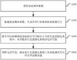
在基于电磁仿真平台搭建对应的模型后,结合图4所示的一种谐波阻抗扫描方法的流程示意图,一种谐波阻抗扫描方法具体步骤如下:After building the corresponding model based on the electromagnetic simulation platform, combined with the schematic flowchart of a harmonic impedance scanning method shown in FIG. 4 , the specific steps of a harmonic impedance scanning method are as follows:
步骤1:获取谐波频率参数;谐波频率参数包括初始扫描频率和扫描频率间隔Δf;初始扫描频率包括最小扫描频率fmin、最大扫描频率fmax;Step 1: obtain harmonic frequency parameters; the harmonic frequency parameters include the initial scanning frequency and the scanning frequency interval Δf; the initial scanning frequency includes the minimum scanning frequency fmin and the maximum scanning frequency fmax ;
步骤2:根据初始扫描频率和扫描频率间隔,确定预设数量个扫描频率;确定预设数量
步骤3:获取待生成谐波源信号的初始相位和相位差值;相位差值包括多种不同的相位差值;Step 3: obtaining the initial phase and phase difference value of the harmonic source signal to be generated; the phase difference value includes a variety of different phase difference values;
步骤4:根据初始相位和相位差值,确定与各扫描频率对应的目标初始相位值;Step 4: Determine the target initial phase value corresponding to each scanning frequency according to the initial phase and the phase difference value;
步骤5:针对每种相位差值,依据各扫描频率和各目标初始相位值,生成不同扫描频率的谐波源信号;Step 5: For each phase difference value, according to each scanning frequency and each target initial phase value, generate harmonic source signals of different scanning frequencies;
步骤6:统计相同相位差值对应的谐波源信号的谐波源总幅值;Step 6: Count the total amplitude of the harmonic source of the harmonic source signal corresponding to the same phase difference value;
步骤7:确定谐波总幅值的最小值,并将谐波源总幅值的最小值对应的相位差值确定目标相位差值;Step 7: Determine the minimum value of the total harmonic amplitude value, and determine the target phase difference value corresponding to the phase difference value corresponding to the minimum value of the total harmonic amplitude value;
步骤8:将不同扫描频率的谐波源信号同时注入至高压直流输电系统中,并采集高压直流输电系统的电信号值;Step 8: injecting harmonic source signals of different scanning frequencies into the HVDC transmission system at the same time, and collecting the electrical signal values of the HVDC transmission system;
具体的,启动直流输电系统运行至稳态时,开始注入谐波电压源:如图3所示,若需要求取换流器交流等值正序阻抗ZHAC时,则注入三相正序谐波电压源UACN;若需要求取换流器直流侧相关等值阻抗ZHDC时,则注入单相谐波电压源UDCN;待直流输电系统过渡到稳态后,对交流(或直流)侧等值阻抗进行扫描,采集交流侧m点(或直流侧m1点和m2点)电压电流采样值。Specifically, when the DC transmission system is started to run to a steady state, the harmonic voltage source is injected: as shown in Figure 3, if the AC equivalent positive sequence impedance ZHAC of the converter needs to be obtained, the three-phase positive sequence harmonic is injected. wave voltage source UACN ; if it is necessary to obtain the relevant equivalent impedance ZHDC on the DC side of the converter, inject the single-phase harmonic voltage source UDCN ; after the DC transmission system transitions to a steady state, the AC (or DC) Scan the equivalent impedance of the side, and collect the voltage and current sampling values of point m on the AC side (or points m1 and m2 on the DC side).
步骤9:根据电信号值,确定高压直流输电系统与各谐波源信号对应的谐波阻抗值;Step 9: According to the electrical signal value, determine the harmonic impedance value corresponding to each harmonic source signal of the HVDC transmission system;
利用离散傅里叶变换(DFT)和序分量相量算法计算对应谐波源频率下的换流器交流(或直流)等值阻抗,计算公式如下,得到不同扫描频率对应的谐波阻抗值。Use discrete Fourier transform (DFT) and sequence component phasor algorithm to calculate the AC (or DC) equivalent impedance of the converter at the corresponding harmonic source frequency. The calculation formula is as follows, and the harmonic impedance values corresponding to different scanning frequencies are obtained.

式中:


上述谐波阻抗扫描方法中,在获取谐波频率参数后,依据谐波频率参数生成不同扫描频率的谐波源信号,然后将不同扫描频率的谐波源信号同时注入至高压直流输电系统中,并采集高压直流输电系统的电信号值;根据电信号值,确定高压直流输电系统与各谐波源信号分别对应的谐波阻抗值;通过采集同时注入高压直流输电系统中的不同扫描频率的谐波源信号对应的电信号值,避免需要针对各谐波源信号分别采集对应的电信号值;再依据采集到的电信号值确定高压直流输电系统中与各谐波源信号分别对应的谐波阻抗值,能够根据单次采集的电信号值批量确定出不同谐波源信号对应的谐波阻抗值,因此本方案能高效便捷地对高压直流输电系统进行谐波阻抗扫描。并且,本方法通过寻找各谐波源信号的最优相位差值,使得在向高压直流输电系统注入谐波源信号时,对高压直流输电系统的冲击最小,提升高压直流输电系统的谐波阻抗扫描结果的可靠性和准确度。In the above harmonic impedance scanning method, after obtaining the harmonic frequency parameters, the harmonic source signals of different scanning frequencies are generated according to the harmonic frequency parameters, and then the harmonic source signals of different scanning frequencies are injected into the HVDC transmission system at the same time, And collect the electrical signal values of the HVDC transmission system; according to the electrical signal values, determine the harmonic impedance values corresponding to the HVDC transmission system and each harmonic source signal respectively; The electrical signal value corresponding to the wave source signal avoids the need to separately collect the corresponding electrical signal value for each harmonic source signal; and then determine the harmonic corresponding to each harmonic source signal in the HVDC transmission system according to the collected electrical signal values. The impedance value can be determined in batches according to the electrical signal value collected in a single time, and the harmonic impedance values corresponding to different harmonic source signals can be determined in batches. Therefore, this solution can efficiently and conveniently perform harmonic impedance scanning on the HVDC transmission system. In addition, by finding the optimal phase difference value of each harmonic source signal, the method makes the impact on the HVDC transmission system minimal when injecting the harmonic source signal into the HVDC transmission system, and improves the harmonic impedance of the HVDC transmission system. Reliability and accuracy of scan results.
应该理解的是,虽然如上的各实施例所涉及的流程图中的各个步骤按照箭头的指示依次显示,但是这些步骤并不是必然按照箭头指示的顺序依次执行。除非本文中有明确的说明,这些步骤的执行并没有严格的顺序限制,这些步骤可以以其它的顺序执行。而且,如上的各实施例所涉及的流程图中的至少一部分步骤可以包括多个步骤或者多个阶段,这些步骤或者阶段并不必然是在同一时刻执行完成,而是可以在不同的时刻执行,这些步骤或者阶段的执行顺序也不必然是依次进行,而是可以与其它步骤或者其它步骤中的步骤或者阶段的至少一部分轮流或者交替地执行。It should be understood that, although the steps in the flowcharts involved in the above embodiments are sequentially displayed according to the arrows, these steps are not necessarily executed in the order indicated by the arrows. Unless explicitly stated herein, the execution of these steps is not strictly limited to the order, and these steps may be performed in other orders. Moreover, at least a part of the steps in the flowcharts involved in the above embodiments may include multiple steps or multiple stages. These steps or stages are not necessarily executed at the same time, but may be executed at different times. The order of execution of these steps or stages is also not necessarily sequential, but may be performed alternately or alternately with other steps or at least a portion of the steps or stages in the other steps.
基于同样的发明构思,本申请实施例还提供了一种用于实现上述所涉及的谐波阻抗扫描方法的谐波阻抗扫描装置。该装置所提供的解决问题的实现方案与上述方法中所记载的实现方案相似,故下面所提供的一个或多个谐波阻抗扫描装置实施例中的具体限定可以参见上文中对于谐波阻抗扫描方法的限定,在此不再赘述。Based on the same inventive concept, an embodiment of the present application also provides a harmonic impedance scanning device for implementing the above-mentioned harmonic impedance scanning method. The solution to the problem provided by the device is similar to the solution described in the above method, so the specific limitations in one or more embodiments of the harmonic impedance scanning device provided below can refer to the above for harmonic impedance scanning The limitation of the method is not repeated here.
在一个实施例中,如图5所示,提供了一种谐波阻抗扫描装置,包括:获取模块502、第一确定模块504、输入模块506和第二确定模块508,其中:In one embodiment, as shown in FIG. 5, a harmonic impedance scanning device is provided, including: an
获取模块502,用于获取谐波频率参数;an
第一确定模块504,用于依据谐波频率参数,生成不同扫描频率的谐波源信号;a
输入模块506,用于将不同扫描频率的谐波源信号同时注入至高压直流输电系统中,并采集高压直流输电系统的电信号值;The
第二确定模块508,用于根据电信号值,确定高压直流输电系统与各谐波源信号对应的谐波阻抗值。The second determining
本申请实施例提供的一种谐波阻抗扫描装置,具有与上述一种谐波阻抗扫描方法相同的有益效果。The harmonic impedance scanning device provided by the embodiment of the present application has the same beneficial effects as the above-mentioned harmonic impedance scanning method.
在其中一个实施例中,谐波频率参数包括初始扫描频率和扫描频率间隔;第一确定模块包括:In one of the embodiments, the harmonic frequency parameter includes an initial scanning frequency and a scanning frequency interval; the first determining module includes:
第一确定子模块,用于根据初始扫描频率和扫描频率间隔,确定预设数量个扫描频率;a first determination submodule, used for determining a preset number of scan frequencies according to the initial scan frequency and the scan frequency interval;
获取子模块,用于获取待生成谐波源信号的初始相位和相位差值;The acquisition sub-module is used to acquire the initial phase and phase difference value of the harmonic source signal to be generated;
第二确定子模块,用于根据初始相位和相位差值,确定与各扫描频率对应的目标初始相位值;The second determination sub-module is used to determine the target initial phase value corresponding to each scanning frequency according to the initial phase and the phase difference value;
生成子模块,用于依据各扫描频率和各目标初始相位值,生成不同扫描频率的谐波源信号。The generating sub-module is used to generate harmonic source signals of different scanning frequencies according to each scanning frequency and each target initial phase value.
在其中一个实施例中,相位差值包括多种不同的相位差值;第二确定子模块包括:In one of the embodiments, the phase difference value includes a variety of different phase difference values; the second determination submodule includes:
第一确定单元,用于针对每种相位差值,依据各扫描频率和各目标初始相位值,生成不同扫描频率的谐波源信号目标初始相位值。The first determining unit is configured to, for each phase difference value, generate target initial phase values of harmonic source signals of different scanning frequencies according to each scanning frequency and each target initial phase value.
在其中一个实施例中,一种谐波阻抗扫描装置还包括:In one of the embodiments, a harmonic impedance scanning device further includes:
统计模块,用于统计相同相位差值对应的谐波源信号的谐波源总幅值;The statistics module is used to count the total amplitude of the harmonic source of the harmonic source signal corresponding to the same phase difference value;
目标确定模块,用于确定谐波总幅值的最小值,并将谐波源总幅值的最小值对应的相位差值确定目标相位差值;The target determination module is used for determining the minimum value of the total harmonic amplitude value, and determining the target phase difference value corresponding to the phase difference value corresponding to the minimum value of the total harmonic amplitude value;
第二确定子模块包括:The second determination submodule includes:
第二确定单元,用于根据初始相位和目标相位差值,确定与各扫描频率对应的目标初始相位值。The second determining unit is configured to determine the target initial phase value corresponding to each scanning frequency according to the initial phase and the target phase difference value.
在其中一个实施例中,一种谐波阻抗扫描装置还包括:In one of the embodiments, a harmonic impedance scanning device further includes:
提示模块,用于确定谐波源总幅值是否小于预设幅值阈值;若谐波源总幅值小于预设幅值阈值,则调用目标确定模块;若否,生成提示信息;提示信息用于提示谐波源总幅值异常。The prompt module is used to determine whether the total amplitude of the harmonic source is less than the preset amplitude threshold; if the total amplitude of the harmonic source is less than the preset amplitude threshold, the target determination module is called; if not, a prompt message is generated; Indicates that the total amplitude of the harmonic source is abnormal.
在其中一个实施例中,谐波源信号包括谐波电压源信号和谐波电流源信号。In one of the embodiments, the harmonic source signal includes a harmonic voltage source signal and a harmonic current source signal.
上述谐波阻抗扫描装置中的各个模块可全部或部分通过软件、硬件及其组合来实现。上述各模块可以硬件形式内嵌于或独立于计算机设备中的处理器中,也可以以软件形式存储于计算机设备中的存储器中,以便于处理器调用执行以上各个模块对应的操作。Each module in the above harmonic impedance scanning device can be implemented in whole or in part by software, hardware and combinations thereof. The above modules can be embedded in or independent of the processor in the computer device in the form of hardware, or stored in the memory in the computer device in the form of software, so that the processor can call and execute the operations corresponding to the above modules.
在一个实施例中,提供了一种计算机设备,该计算机设备可以是终端,其内部结构图可以如图6所示。该计算机设备包括通过系统总线连接的处理器、存储器、通信接口、显示屏和输入装置。其中,该计算机设备的处理器用于提供计算和控制能力。该计算机设备的存储器包括非易失性存储介质、内存储器。该非易失性存储介质存储有操作系统和计算机程序。该内存储器为非易失性存储介质中的操作系统和计算机程序的运行提供环境。该计算机设备的通信接口用于与外部的终端进行有线或无线方式的通信,无线方式可通过WIFI、移动蜂窝网络、NFC(近场通信)或其他技术实现。该计算机程序被处理器执行时以实现一种谐波阻抗扫描方法。该计算机设备的显示屏可以是液晶显示屏或者电子墨水显示屏,该计算机设备的输入装置可以是显示屏上覆盖的触摸层,也可以是计算机设备外壳上设置的按键、轨迹球或触控板,还可以是外接的键盘、触控板或鼠标等。In one embodiment, a computer device is provided, and the computer device may be a terminal, and its internal structure diagram may be as shown in FIG. 6 . The computer equipment includes a processor, memory, a communication interface, a display screen, and an input device connected by a system bus. Among them, the processor of the computer device is used to provide computing and control capabilities. The memory of the computer device includes a non-volatile storage medium, an internal memory. The nonvolatile storage medium stores an operating system and a computer program. The internal memory provides an environment for the execution of the operating system and computer programs in the non-volatile storage medium. The communication interface of the computer device is used for wired or wireless communication with an external terminal, and the wireless communication can be realized by WIFI, mobile cellular network, NFC (Near Field Communication) or other technologies. The computer program, when executed by a processor, implements a harmonic impedance scanning method. The display screen of the computer equipment may be a liquid crystal display screen or an electronic ink display screen, and the input device of the computer equipment may be a touch layer covered on the display screen, or a button, a trackball or a touchpad set on the shell of the computer equipment , or an external keyboard, trackpad, or mouse.
本领域技术人员可以理解,图6中示出的结构,仅仅是与本申请方案相关的部分结构的框图,并不构成对本申请方案所应用于其上的计算机设备的限定,具体的计算机设备可以包括比图中所示更多或更少的部件,或者组合某些部件,或者具有不同的部件布置。Those skilled in the art can understand that the structure shown in FIG. 6 is only a block diagram of a part of the structure related to the solution of the present application, and does not constitute a limitation on the computer equipment to which the solution of the present application is applied. Include more or fewer components than shown in the figures, or combine certain components, or have a different arrangement of components.
在一个实施例中,提供了一种计算机设备,包括存储器和处理器,存储器中存储有计算机程序,该处理器执行计算机程序时实现上述方法的步骤。In one embodiment, a computer device is provided, comprising a memory and a processor, a computer program is stored in the memory, and the processor implements the steps of the above method when executing the computer program.
本申请实施例提供的一种计算机设备,具有与上述一种谐波阻抗扫描方法相同的有益效果。The computer equipment provided by the embodiment of the present application has the same beneficial effects as the above-mentioned harmonic impedance scanning method.
在一个实施例中,提供了一种计算机可读存储介质,其上存储有计算机程序,计算机程序被处理器执行时实现上述方法的步骤。In one embodiment, there is provided a computer-readable storage medium having a computer program stored thereon, the computer program implementing the steps of the above method when executed by a processor.
本申请实施例提供的一种计算机可读存储介质,具有与上述一种谐波阻抗扫描方法相同的有益效果。The computer-readable storage medium provided by the embodiment of the present application has the same beneficial effects as the above-mentioned harmonic impedance scanning method.
在一个实施例中,提供了一种计算机程序产品,包括计算机程序,该计算机程序被处理器执行时实现上述方法的步骤。In one embodiment, a computer program product is provided, comprising a computer program that, when executed by a processor, implements the steps of the above-described method.
本申请实施例提供的一种计算机程序产品,具有与上述一种谐波阻抗扫描方法相同的有益效果。A computer program product provided by an embodiment of the present application has the same beneficial effects as the above-mentioned harmonic impedance scanning method.
需要说明的是,本申请所涉及的用户信息(包括但不限于用户设备信息、用户个人信息等)和数据(包括但不限于用于分析的数据、存储的数据、展示的数据等),均为经用户授权或者经过各方充分授权的信息和数据。It should be noted that the user information (including but not limited to user equipment information, user personal information, etc.) and data (including but not limited to data for analysis, stored data, displayed data, etc.) involved in this application are all Information and data authorized by the user or fully authorized by the parties.
本领域普通技术人员可以理解实现上述实施例方法中的全部或部分流程,是可以通过计算机程序来指令相关的硬件来完成,所述的计算机程序可存储于一非易失性计算机可读取存储介质中,该计算机程序在执行时,可包括如上述各方法的实施例的流程。其中,本申请所提供的各实施例中所使用的对存储器、数据库或其它介质的任何引用,均可包括非易失性和易失性存储器中的至少一种。非易失性存储器可包括只读存储器(Read-OnlyMemory,ROM)、磁带、软盘、闪存、光存储器、高密度嵌入式非易失性存储器、阻变存储器(ReRAM)、磁变存储器(Magnetoresistive Random Access Memory,MRAM)、铁电存储器(Ferroelectric Random Access Memory,FRAM)、相变存储器(Phase Change Memory,PCM)、石墨烯存储器等。易失性存储器可包括随机存取存储器(Random Access Memory,RAM)或外部高速缓冲存储器等。作为说明而非局限,RAM可以是多种形式,比如静态随机存取存储器(Static Random Access Memory,SRAM)或动态随机存取存储器(Dynamic RandomAccess Memory,DRAM)等。本申请所提供的各实施例中所涉及的数据库可包括关系型数据库和非关系型数据库中至少一种。非关系型数据库可包括基于区块链的分布式数据库等,不限于此。本申请所提供的各实施例中所涉及的处理器可为通用处理器、中央处理器、图形处理器、数字信号处理器、可编程逻辑器、基于量子计算的数据处理逻辑器等,不限于此。Those of ordinary skill in the art can understand that all or part of the processes in the methods of the above embodiments can be implemented by instructing relevant hardware through a computer program, and the computer program can be stored in a non-volatile computer-readable storage In the medium, when the computer program is executed, it may include the processes of the above-mentioned method embodiments. Wherein, any reference to a memory, a database or other media used in the various embodiments provided in this application may include at least one of a non-volatile memory and a volatile memory. Non-volatile memory may include Read-Only Memory (ROM), magnetic tape, floppy disk, flash memory, optical memory, high-density embedded non-volatile memory, resistive memory (ReRAM), magnetic variable memory (Magnetoresistive Random Memory) Access Memory, MRAM), Ferroelectric Random Access Memory (FRAM), Phase Change Memory (Phase Change Memory, PCM), graphene memory, etc. Volatile memory may include random access memory (Random Access Memory, RAM) or external cache memory, and the like. By way of illustration and not limitation, the RAM may be in various forms, such as static random access memory (Static Random Access Memory, SRAM) or dynamic random access memory (Dynamic Random Access Memory, DRAM). The database involved in the various embodiments provided in this application may include at least one of a relational database and a non-relational database. The non-relational database may include a blockchain-based distributed database, etc., but is not limited thereto. The processors involved in the various embodiments provided in this application may be general-purpose processors, central processing units, graphics processors, digital signal processors, programmable logic devices, data processing logic devices based on quantum computing, etc., and are not limited to this.
以上实施例的各技术特征可以进行任意的组合,为使描述简洁,未对上述实施例中的各个技术特征所有可能的组合都进行描述,然而,只要这些技术特征的组合不存在矛盾,都应当认为是本说明书记载的范围。The technical features of the above embodiments can be combined arbitrarily. In order to make the description simple, all possible combinations of the technical features in the above embodiments are not described. However, as long as there is no contradiction in the combination of these technical features It is considered to be the range described in this specification.
以上所述实施例仅表达了本申请的几种实施方式,其描述较为具体和详细,但并不能因此而理解为对本申请专利范围的限制。应当指出的是,对于本领域的普通技术人员来说,在不脱离本申请构思的前提下,还可以做出若干变形和改进,这些都属于本申请的保护范围。因此,本申请的保护范围应以所附权利要求为准。The above-mentioned embodiments only represent several embodiments of the present application, and the descriptions thereof are relatively specific and detailed, but should not be construed as a limitation on the scope of the patent of the present application. It should be pointed out that for those skilled in the art, without departing from the concept of the present application, several modifications and improvements can be made, which all belong to the protection scope of the present application. Therefore, the scope of protection of the present application should be determined by the appended claims.
Claims (10)
Priority Applications (1)
| Application Number | Priority Date | Filing Date | Title |
|---|---|---|---|
| CN202210681015.3ACN115219791A (en) | 2022-06-16 | 2022-06-16 | Harmonic impedance scanning method |
Applications Claiming Priority (1)
| Application Number | Priority Date | Filing Date | Title |
|---|---|---|---|
| CN202210681015.3ACN115219791A (en) | 2022-06-16 | 2022-06-16 | Harmonic impedance scanning method |
Publications (1)
| Publication Number | Publication Date |
|---|---|
| CN115219791Atrue CN115219791A (en) | 2022-10-21 |
Family
ID=83607818
Family Applications (1)
| Application Number | Title | Priority Date | Filing Date |
|---|---|---|---|
| CN202210681015.3APendingCN115219791A (en) | 2022-06-16 | 2022-06-16 | Harmonic impedance scanning method |
Country Status (1)
| Country | Link |
|---|---|
| CN (1) | CN115219791A (en) |
Cited By (2)
| Publication number | Priority date | Publication date | Assignee | Title |
|---|---|---|---|---|
| WO2024230628A1 (en)* | 2023-05-05 | 2024-11-14 | 中国南方电网有限责任公司超高压输电公司电力科研院 | Impedance measurement method and apparatus for grid-forming converter, device, and storage medium |
| CN119619645A (en)* | 2024-11-06 | 2025-03-14 | 国网湖南省电力有限公司 | Flexible DC high-speed frequency scanning method and system with multi-harmonic injection |
Citations (5)
| Publication number | Priority date | Publication date | Assignee | Title |
|---|---|---|---|---|
| CN101706532A (en)* | 2009-11-25 | 2010-05-12 | 国网电力科学研究院武汉南瑞有限责任公司 | Method and device for measuring harmonic impedance |
| CN108196127A (en)* | 2018-01-22 | 2018-06-22 | 华北电力大学 | Harmonic impedance scanning method and device for high-voltage direct-current transmission system |
| CN109030950A (en)* | 2018-08-06 | 2018-12-18 | 南方电网科学研究院有限责任公司 | Impedance scanning method and system for power electronic equipment |
| CN111157794A (en)* | 2020-01-19 | 2020-05-15 | 中国南方电网有限责任公司超高压输电公司检修试验中心 | Method and system for quickly calculating harmonic impedance of flexible direct current transmission system |
| CN112131816A (en)* | 2020-09-22 | 2020-12-25 | 清华四川能源互联网研究院 | Method, device, medium and equipment for determining harmonic source amplitude of harmonic impedance scanning |
- 2022
- 2022-06-16CNCN202210681015.3Apatent/CN115219791A/enactivePending
Patent Citations (5)
| Publication number | Priority date | Publication date | Assignee | Title |
|---|---|---|---|---|
| CN101706532A (en)* | 2009-11-25 | 2010-05-12 | 国网电力科学研究院武汉南瑞有限责任公司 | Method and device for measuring harmonic impedance |
| CN108196127A (en)* | 2018-01-22 | 2018-06-22 | 华北电力大学 | Harmonic impedance scanning method and device for high-voltage direct-current transmission system |
| CN109030950A (en)* | 2018-08-06 | 2018-12-18 | 南方电网科学研究院有限责任公司 | Impedance scanning method and system for power electronic equipment |
| CN111157794A (en)* | 2020-01-19 | 2020-05-15 | 中国南方电网有限责任公司超高压输电公司检修试验中心 | Method and system for quickly calculating harmonic impedance of flexible direct current transmission system |
| CN112131816A (en)* | 2020-09-22 | 2020-12-25 | 清华四川能源互联网研究院 | Method, device, medium and equipment for determining harmonic source amplitude of harmonic impedance scanning |
Cited By (2)
| Publication number | Priority date | Publication date | Assignee | Title |
|---|---|---|---|---|
| WO2024230628A1 (en)* | 2023-05-05 | 2024-11-14 | 中国南方电网有限责任公司超高压输电公司电力科研院 | Impedance measurement method and apparatus for grid-forming converter, device, and storage medium |
| CN119619645A (en)* | 2024-11-06 | 2025-03-14 | 国网湖南省电力有限公司 | Flexible DC high-speed frequency scanning method and system with multi-harmonic injection |
Similar Documents
| Publication | Publication Date | Title |
|---|---|---|
| CN115219791A (en) | Harmonic impedance scanning method | |
| CN108196127B (en) | Harmonic impedance scanning method and device for HVDC transmission system | |
| CN116449106A (en) | Impedance detection method, device, equipment and storage medium of network-structured converter | |
| CN114398803B (en) | Shim-field co-simulation method, device, electronic device and storage medium | |
| CN113533923A (en) | GaN HEMT device testing method and device | |
| CN118759264A (en) | A method, device and medium for measuring impedance of a converter black box | |
| CN118937796A (en) | Impedance measurement method, device, equipment, readable storage medium and program product | |
| CN114417935A (en) | Method, device and equipment for determining decomposition modal number in variational modal decomposition | |
| Wang et al. | Unbalanced responsibility division considering renewable energy integration | |
| CN112131816A (en) | Method, device, medium and equipment for determining harmonic source amplitude of harmonic impedance scanning | |
| CN114709822A (en) | AC-DC complementary resonance detection method, device, storage medium, computer equipment | |
| US9507894B1 (en) | Automatic harmonic number identification for harmonic balance analysis | |
| CN116804728A (en) | Harmonic transmission characteristic detection method, device and equipment of capacitive voltage transformer | |
| CN110752607A (en) | Impedance analysis method and device for flexible direct current transmission converter and storage medium | |
| CN114935687B (en) | Load harmonic emission characteristic extraction method and device and computer equipment | |
| CN115236450B (en) | Filter loss detection method, device, computer equipment, and storage medium | |
| CN113341228A (en) | Voltage phase difference processing method and device, electronic equipment and storage medium | |
| CN110545516A (en) | A detection method and detection device for coil equipment faults | |
| CN120334608A (en) | Method, device, computer equipment, readable storage medium and program product for determining harmonic impedance | |
| CN117674187A (en) | An adjustment method for voltage excitation signal amplitude suitable for reverse impedance modeling | |
| CN117725462A (en) | Method and device for classifying voltage sag, computer equipment and storage medium | |
| CN119864831B (en) | A method, system, device and medium for simulating broadband oscillation of wind turbine grid-connected | |
| CN115267350B (en) | Loss analysis method, device and computer equipment for converter transformer | |
| CN116131242A (en) | Method and device for determining direct current ripple current, electronic equipment and storage medium | |
| CN115524555B (en) | Method, device, equipment and medium for determining steady-state constant value of alternating current filter |
Legal Events
| Date | Code | Title | Description |
|---|---|---|---|
| PB01 | Publication | ||
| PB01 | Publication | ||
| SE01 | Entry into force of request for substantive examination | ||
| SE01 | Entry into force of request for substantive examination | ||
| CB02 | Change of applicant information | Country or region after:China Address after:No. 223, Kexue Avenue, Huangpu District, Guangzhou City, Guangdong Province, 510663 Applicant after:China Southern Power Grid Corporation Ultra High Voltage Transmission Company Electric Power Research Institute Address before:No. 223, Kexue Avenue, Huangpu District, Guangzhou City, Guangdong Province, 510663 Applicant before:MAINTENANCE & TEST CENTRE, CSG EHV POWER TRANSMISSION Co. Country or region before:China | |
| CB02 | Change of applicant information | ||
| RJ01 | Rejection of invention patent application after publication | Application publication date:20221021 | |
| RJ01 | Rejection of invention patent application after publication |