CN115210046A - Compact type transverse moving robot - Google Patents
Compact type transverse moving robotDownload PDFInfo
- Publication number
- CN115210046A CN115210046ACN202180018357.0ACN202180018357ACN115210046ACN 115210046 ACN115210046 ACN 115210046ACN 202180018357 ACN202180018357 ACN 202180018357ACN 115210046 ACN115210046 ACN 115210046A
- Authority
- CN
- China
- Prior art keywords
- platform
- link
- actuator
- spindle
- traverse
- Prior art date
- Legal status (The legal status is an assumption and is not a legal conclusion. Google has not performed a legal analysis and makes no representation as to the accuracy of the status listed.)
- Pending
Links
Images


Classifications
- B—PERFORMING OPERATIONS; TRANSPORTING
- B25—HAND TOOLS; PORTABLE POWER-DRIVEN TOOLS; MANIPULATORS
- B25J—MANIPULATORS; CHAMBERS PROVIDED WITH MANIPULATION DEVICES
- B25J9/00—Programme-controlled manipulators
- B25J9/02—Programme-controlled manipulators characterised by movement of the arms, e.g. cartesian coordinate type
- B25J9/04—Programme-controlled manipulators characterised by movement of the arms, e.g. cartesian coordinate type by rotating at least one arm, excluding the head movement itself, e.g. cylindrical coordinate type or polar coordinate type
- B25J9/041—Cylindrical coordinate type
- B25J9/042—Cylindrical coordinate type comprising an articulated arm
- B25J9/044—Cylindrical coordinate type comprising an articulated arm with forearm providing vertical linear movement
- B—PERFORMING OPERATIONS; TRANSPORTING
- B25—HAND TOOLS; PORTABLE POWER-DRIVEN TOOLS; MANIPULATORS
- B25J—MANIPULATORS; CHAMBERS PROVIDED WITH MANIPULATION DEVICES
- B25J11/00—Manipulators not otherwise provided for
- B25J11/0095—Manipulators transporting wafers
- B—PERFORMING OPERATIONS; TRANSPORTING
- B25—HAND TOOLS; PORTABLE POWER-DRIVEN TOOLS; MANIPULATORS
- B25J—MANIPULATORS; CHAMBERS PROVIDED WITH MANIPULATION DEVICES
- B25J19/00—Accessories fitted to manipulators, e.g. for monitoring, for viewing; Safety devices combined with or specially adapted for use in connection with manipulators
- B25J19/0008—Balancing devices
- B25J19/0016—Balancing devices using springs
- B—PERFORMING OPERATIONS; TRANSPORTING
- B25—HAND TOOLS; PORTABLE POWER-DRIVEN TOOLS; MANIPULATORS
- B25J—MANIPULATORS; CHAMBERS PROVIDED WITH MANIPULATION DEVICES
- B25J5/00—Manipulators mounted on wheels or on carriages
- B25J5/02—Manipulators mounted on wheels or on carriages travelling along a guideway
- B—PERFORMING OPERATIONS; TRANSPORTING
- B25—HAND TOOLS; PORTABLE POWER-DRIVEN TOOLS; MANIPULATORS
- B25J—MANIPULATORS; CHAMBERS PROVIDED WITH MANIPULATION DEVICES
- B25J9/00—Programme-controlled manipulators
- B25J9/0009—Constructional details, e.g. manipulator supports, bases
- B—PERFORMING OPERATIONS; TRANSPORTING
- B25—HAND TOOLS; PORTABLE POWER-DRIVEN TOOLS; MANIPULATORS
- B25J—MANIPULATORS; CHAMBERS PROVIDED WITH MANIPULATION DEVICES
- B25J9/00—Programme-controlled manipulators
- B25J9/02—Programme-controlled manipulators characterised by movement of the arms, e.g. cartesian coordinate type
- B25J9/04—Programme-controlled manipulators characterised by movement of the arms, e.g. cartesian coordinate type by rotating at least one arm, excluding the head movement itself, e.g. cylindrical coordinate type or polar coordinate type
- B25J9/041—Cylindrical coordinate type
- B25J9/042—Cylindrical coordinate type comprising an articulated arm
- B—PERFORMING OPERATIONS; TRANSPORTING
- B25—HAND TOOLS; PORTABLE POWER-DRIVEN TOOLS; MANIPULATORS
- B25J—MANIPULATORS; CHAMBERS PROVIDED WITH MANIPULATION DEVICES
- B25J9/00—Programme-controlled manipulators
- B25J9/10—Programme-controlled manipulators characterised by positioning means for manipulator elements
- B25J9/1005—Programme-controlled manipulators characterised by positioning means for manipulator elements comprising adjusting means
- B—PERFORMING OPERATIONS; TRANSPORTING
- B25—HAND TOOLS; PORTABLE POWER-DRIVEN TOOLS; MANIPULATORS
- B25J—MANIPULATORS; CHAMBERS PROVIDED WITH MANIPULATION DEVICES
- B25J9/00—Programme-controlled manipulators
- B25J9/10—Programme-controlled manipulators characterised by positioning means for manipulator elements
- B25J9/106—Programme-controlled manipulators characterised by positioning means for manipulator elements with articulated links
- B25J9/1065—Programme-controlled manipulators characterised by positioning means for manipulator elements with articulated links with parallelograms
- B—PERFORMING OPERATIONS; TRANSPORTING
- B25—HAND TOOLS; PORTABLE POWER-DRIVEN TOOLS; MANIPULATORS
- B25J—MANIPULATORS; CHAMBERS PROVIDED WITH MANIPULATION DEVICES
- B25J9/00—Programme-controlled manipulators
- B25J9/10—Programme-controlled manipulators characterised by positioning means for manipulator elements
- B25J9/12—Programme-controlled manipulators characterised by positioning means for manipulator elements electric
- B25J9/123—Linear actuators
- B—PERFORMING OPERATIONS; TRANSPORTING
- B25—HAND TOOLS; PORTABLE POWER-DRIVEN TOOLS; MANIPULATORS
- B25J—MANIPULATORS; CHAMBERS PROVIDED WITH MANIPULATION DEVICES
- B25J9/00—Programme-controlled manipulators
- B25J9/10—Programme-controlled manipulators characterised by positioning means for manipulator elements
- B25J9/12—Programme-controlled manipulators characterised by positioning means for manipulator elements electric
- B25J9/126—Rotary actuators
Landscapes
- Engineering & Computer Science (AREA)
- Robotics (AREA)
- Mechanical Engineering (AREA)
- Manipulator (AREA)
- Container, Conveyance, Adherence, Positioning, Of Wafer (AREA)
Abstract
Description
Translated fromChinese技术领域technical field
本文所述的示例和非限制性实施例总体上涉及可用于材料处理真空环境系统和其它应用中的竖直紧凑横移机器人。The examples and non-limiting embodiments described herein relate generally to vertical compact traverse robots that can be used in material handling vacuum environment systems and other applications.
背景技术Background technique
一种材料处理机器人包括连接到驱动单元的机器人臂,该机器人可沿着轨道或轨道系统移动。机器人臂可以包括上连杆,在上连杆上的下连杆,以及在下连杆上的末端执行器,该末端执行器被配置为在材料搬运操作中容纳有效载荷。驱动单元包括连接到机器人臂的主轴组件,用于在Z方向(垂直)上上下移动主轴组件的Z轴机构,以及一个或多个同轴堆叠的电机。机器人臂可以在真空环境中定位和操作,驱动单元可以在大气环境中定位。波纹管可用于容纳机器人臂操作的空间中的真空环境。主轴组件,用于主轴组件的垂直运动的Z轴机构和/或电机的同轴堆叠通常需要机器人操作的真空腔的相当大的深度和体积。A material handling robot includes a robotic arm connected to a drive unit that can move along a track or system of tracks. The robotic arm may include an upper link, a lower link on the upper link, and an end effector on the lower link, the end effector configured to receive a payload during a material handling operation. The drive unit includes a spindle assembly attached to the robotic arm, a Z-axis mechanism for moving the spindle assembly up and down in the Z-direction (vertical), and one or more coaxially stacked motors. The robotic arm can be positioned and operated in a vacuum environment, and the drive unit can be positioned in an atmospheric environment. The bellows can be used to accommodate the vacuum environment in the space where the robotic arm operates. The spindle assembly, the Z-axis mechanism and/or the coaxial stacking of the motors for the vertical motion of the spindle assembly typically requires a considerable depth and volume of the robotically operated vacuum chamber.
发明内容SUMMARY OF THE INVENTION
根据一个方面,一种装置包括主轴平台;横移平台,该横移平台被配置为在第一方向上移动;升降系统,该升降系统被连接到该主轴平台和该横移平台,该升降系统被配置为在收缩位置与伸展位置之间在第二方向上移动该主轴平台,该第二方向垂直于该第一方向;连接到所述主轴平台的至少一个可移动臂,所述至少一个可移动臂包括连接到所述主轴平台的第一连杆、连接到所述第一连杆的第二连杆和连接到所述第二连杆的第三连杆,以及连接到所述主轴平台并且被配置为引起所述第一连杆旋转的至少一个第一致动器,以及在所述至少一个可移动臂中并且被配置为引起所述第二连杆旋转的至少一个第二致动器。第一致动器从主轴平台延伸到第一连杆中以占据主轴平台和第一连杆的组合厚度。According to one aspect, an apparatus includes a spindle platform; a traverse platform configured to move in a first direction; a lift system connected to the spindle platform and the traverse platform, the lift system is configured to move the spindle platform in a second direction between a retracted position and an extended position, the second direction being perpendicular to the first direction; at least one movable arm connected to the spindle platform, the at least one movable arm A moving arm includes a first link connected to the spindle platform, a second link connected to the first link, and a third link connected to the second link, and connected to the spindle platform and at least one first actuator configured to cause rotation of the first link, and at least one second actuator in the at least one movable arm and configured to cause rotation of the second link device. The first actuator extends from the spindle platform into the first link to occupy the combined thickness of the spindle platform and the first link.
根据另一个方面,一种方法包括:提供被配置为在第一方向上移动的横移平台;提供主轴平台;提供连接到所述主轴平台和所述横移平台的升降系统,所述升降系统被配置为使所述主轴平台在第二方向上在收缩位置和伸展位置之间移动,所述第二方向垂直于所述第一方向;以及提供连接到所述主轴平台的至少一个可移动臂,所述至少一个可移动臂包括连接到所述主轴平台的第一连杆、连接到所述第一连杆的第二连杆,以及连接到所述第二连杆的第三连杆;提供至少一个第一致动器,该第一致动器连接到该主轴平台并且被配置为致使该第一连杆旋转,并且在该至少一个可移动臂中提供至少一个第二致动器并且被配置为致使该第二连杆旋转。第一致动器从主轴平台延伸到第一连杆中以占据主轴平台和第一连杆的组合厚度。According to another aspect, a method includes: providing a traverse platform configured to move in a first direction; providing a spindle platform; providing a lift system coupled to the spindle platform and the traverse platform, the lift system being configured to move the spindle platform between a retracted position and an extended position in a second direction, the second direction being perpendicular to the first direction; and providing at least one movable arm connected to the spindle platform , the at least one movable arm includes a first link connected to the spindle platform, a second link connected to the first link, and a third link connected to the second link; at least one first actuator is provided, the first actuator is connected to the spindle platform and configured to cause rotation of the first link, and at least one second actuator is provided in the at least one movable arm and is configured to cause the second link to rotate. The first actuator extends from the spindle platform into the first link to occupy the combined thickness of the spindle platform and the first link.
根据另一方面,一种装置包括:至少一个处理器;以及包括计算机程序代码的至少一个非暂态存储器,该至少一个存储器和该计算机程序代码被配置为与该至少一个处理器一起致使该装置至少执行:在第一方向上移动横移平台;操作连接到所述横移平台和主轴平台的升降系统,以在收缩位置和伸展位置之间在第二方向上移动所述主轴平台,所述第二方向垂直于所述第一方向;操作连接到所述主轴平台的至少一个可移动臂,所述至少一个可移动臂包括连接到所述主轴平台的第一连杆、连接到所述第一连杆的第二连杆,以及连接到所述第二连杆的第三连杆;以及操作至少一个第一致动器装置和至少一个第二致动器装置,所述第一致动器装置连接到所述主轴平台并且被配置为引起所述第一连杆的旋转,所述第二致动器装置在所述至少一个可移动臂中并且被配置为引起所述第二连杆的旋转。第一致动器装置从主轴平台延伸到第一连杆中以占据主轴平台和第一连杆的组合厚度。According to another aspect, an apparatus includes: at least one processor; and at least one non-transitory memory including computer program code, the at least one memory and the computer program code configured to, in conjunction with the at least one processor, cause the apparatus performing at least: moving a traverse platform in a first direction; operating a lift system connected to the traverse platform and spindle platform to move the spindle platform in a second direction between a retracted position and an extended position, the a second direction is perpendicular to the first direction; at least one movable arm operatively connected to the spindle platform, the at least one movable arm including a first link connected to the spindle platform, a first link connected to the spindle platform a second link of a link, and a third link connected to the second link; and operating at least one first actuator arrangement and at least one second actuator arrangement, the first actuating actuator means is connected to the spindle platform and is configured to cause rotation of the first link, the second actuator means is in the at least one movable arm and is configured to cause the second link rotation. The first actuator arrangement extends from the spindle platform into the first link to occupy the combined thickness of the spindle platform and the first link.
根据另一方面,一种装置包括:横向平台,其被配置为在第一方向上移动;主轴平台,所述主轴平台具有第一致动器和连接到所述第一致动器的第一控制器;连接到所述主轴平台的至少一个可移动臂,所述至少一个可移动臂包括连接到所述第一致动器的第一连杆和连接到所述第一连杆的至少一个第二连杆,所述第二连杆包括至少一个第二致动器并且由所述至少一个可移动臂上的第二控制器控制,所述至少一个第一致动器被配置为引起所述第一连杆的旋转,并且所述至少一个第二致动器被配置为引起所述第二连杆的旋转;升降系统,所述升降系统连接到所述主轴平台和所述横向平台,所述升降系统被配置为在收缩位置和伸展位置之间在第二方向上移动所述主轴平台,所述第二方向垂直于所述第一方向,所述升降系统具有在所述横向平台的第三致动器和连接到所述第三致动器的第三控制器。第一致动器从主轴平台延伸到第一连杆中以占据主轴平台和第一连杆的组合厚度。According to another aspect, an apparatus includes: a lateral platform configured to move in a first direction; a spindle platform having a first actuator and a first actuator coupled to the first actuator a controller; at least one movable arm connected to the spindle platform, the at least one movable arm including a first link connected to the first actuator and at least one link connected to the first link A second link comprising at least one second actuator and controlled by a second controller on the at least one movable arm, the at least one first actuator configured to cause the rotation of the first link, and the at least one second actuator is configured to cause rotation of the second link; a lift system connected to the spindle platform and the transverse platform, The lift system is configured to move the spindle platform in a second direction, the second direction being perpendicular to the first direction, between a retracted position and an extended position, the lift system having a position between the lateral platforms A third actuator and a third controller connected to the third actuator. The first actuator extends from the spindle platform into the first link to occupy the combined thickness of the spindle platform and the first link.
附图说明Description of drawings
在以下结合附图的描述中解释了前述方面和其他特征,其中:The foregoing aspects and other features are explained in the following description taken in conjunction with the accompanying drawings, wherein:
图0A-图0C是现有技术的真空环境材料处理横移机器人的各种视图的示意图;0A-0C are schematic diagrams of various views of a prior art vacuum environment material handling traverse robot;
图1A是具有控制器的移动机器人的示意图;1A is a schematic diagram of a mobile robot with a controller;
图1B(1)-图1B(3)是图1A的机器人的各种视图的示意性表示;Figures 1B(1)-1B(3) are schematic representations of various views of the robot of Figure 1A;
图1C(1)和图1C(2)是示出图1A的机器人的内部部件的示意图;Figures 1C(1) and 1C(2) are schematic diagrams showing internal components of the robot of Figure 1A;
图2A-图2D是横移机器人的示意图,示出了控制器相对于横移机器人的电机的位置;2A-2D are schematic diagrams of the traverse robot, showing the position of the controller relative to the motors of the traverse robot;
图3A和图3B是机器人中的部件的内部容积的连接的示意图;3A and 3B are schematic diagrams of the connection of the interior volumes of components in a robot;
图4A(1)-图4A(3)和图4B(1)-图4B(3)是相对于主轴平台和机器人的臂处于不同位置的机器人的示意图;4A(1)-FIG. 4A(3) and FIG. 4B(1)-FIG. 4B(3) are schematic diagrams of robots in different positions relative to the spindle platform and the arms of the robot;
图5A和图5B是机器人的示意图,示出了当主轴平台降低时部件的重叠;5A and 5B are schematic diagrams of the robot showing the overlapping of components when the spindle platform is lowered;
图6是具有平衡特征的机器人的替代示例实施例的示意性表示;FIG. 6 is a schematic representation of an alternate example embodiment of a robot having a balance feature;
图7A-图7C是用于机器人的升降机构的替代示例实施例的示意性表示;7A-7C are schematic representations of alternative example embodiments of a lift mechanism for a robot;
图7D(1)和图7D(2)是示例机器人的示意图,其中主轴平台由线性轴承支撑并且由滚珠丝杠驱动器致动;7D(1) and 7D(2) are schematic diagrams of an example robot with a spindle stage supported by linear bearings and actuated by a ball screw drive;
图7E是示例机器人的示意图,其中致动电机位于机器人的臂中;7E is a schematic diagram of an example robot with actuation motors located in the arms of the robot;
图7F(1)和图7F(2)是没有升降机构的示例机器人的示意图;Figures 7F(1) and 7F(2) are schematic diagrams of an example robot without a lift mechanism;
图7G(1)-图7G(4)是示出结构比较的示例机器人的示意图;以及7G(1)-7G(4) are schematic diagrams of example robots showing structural comparisons; and
图8是具有上臂和两个前臂的机器人臂的示意图。Figure 8 is a schematic diagram of a robotic arm with an upper arm and two forearms.
具体实施方式Detailed ways
尽管将参考附图中示出的示例实施例来描述特征,但是应当理解,特征可以以实施例的许多替代形式来体现。此外,可以使用任何合适尺寸、形状或类型的元件或材料。Although the features will be described with reference to example embodiments shown in the drawings, it should be understood that the features may be embodied in many alternative forms of embodiments. Furthermore, any suitable size, shape or type of elements or materials may be used.
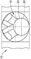
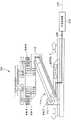
参考图0A-图0C,现有技术的真空环境材料处理移动机器人的一个示例总体上以10示出,并且在下文中被称为“机器人10”。机器人10包括连接到驱动单元14的机器人臂12,机器人臂12可以在真空环境中定位和操作,驱动单元14可以在大气环境中定位。如图所示,机器人臂12包括上连杆16、两个下连杆18和两个末端执行器20,每个下连杆18上有一个末端执行器20。驱动单元14包括耦合到机器人臂12的主轴组件24、用于上下移动主轴组件24从而提供机器人臂12在Z方向上的竖直致动的Z轴机构26(例如滚珠丝杠)、以及一个或多个同轴堆叠的电机28。波纹管30可用于容纳机器人臂12操作的空间中的真空环境。机器人10可以沿着轨道34或导轨在X方向上平移(在图0A中以箭头X示出)。如图0B所示,机器人10可以沿着两个轨道34或导轨平移。在缩回位置处,顶部末端执行器20可以闭塞下端执行器20,如图0C所示。Referring to Figures OA-OC, one example of a prior art vacuum environment material handling mobile robot is shown generally at 10 and is hereinafter referred to as "
本发明的一个目的是减小机器人所占据的竖直空间,从而减小机器人操作的真空室的深度和体积。It is an object of the present invention to reduce the vertical space occupied by the robot, thereby reducing the depth and volume of the vacuum chamber in which the robot operates.
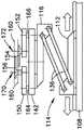
根据本发明的横移机器人的示例实施例在图1A-图1C(2)中示意性地示出,并且在下文中称为“机器人100”。图1A是具有控制系统106的机器人100的侧视图。在图1B(1)-图1B(3)中提供了机器人100的附加视图,并且在图1C(1)和图1C(2)中示意性地示出了机器人100的内部部件的示例布置。An example embodiment of a traversing robot according to the present invention is shown schematically in FIGS. 1A-1C( 2 ) and is hereinafter referred to as “
如图1A所示,机器人100可以由固定基部108支撑,并且可以包括线性引导和致动系统110、横移平台112、升降机构114、主轴平台116、机器人臂120和控制系统106。As shown in FIG. 1A ,
固定基部108可以是被配置为支撑机器人100的结构。作为示例,固定基部108可以是沿机器人100的横移运动方向(例如,沿X轴的X方向)延伸的板或框架、真空室的地板或壁、或能够支撑机器人100的任何其他合适的结构。The
线性引导和致动系统110可以包括线性引导装置和线性致动装置,所述线性引导装置和线性致动装置被配置为促进横移平台112相对于固定基部108的横移运动(例如,在图1A中沿X轴的方向)。Linear guide and
如图1A的示例中示意性所示,线性引导装置可以由线性轴承装置形成。例如,线性轴承装置可以包括附接到固定基部108的一个或多个线性轴承导轨124和附接到横移平台112的一个或多个线性轴承座126。线性引导和致动系统110的线性引导部分可以包括屏蔽系统,该屏蔽系统被配置为防止与线性轴承导轨124接触、防止碎屑污染线性轴承座126(或其它(一个或多个)线性轴承),并防止颗粒迁移出线性轴承座126(或其它(一个或多个)线性轴承)。As schematically shown in the example of Fig. 1A, the linear guide arrangement may be formed by a linear bearing arrangement. For example, the linear bearing arrangement may include one or more linear bearing rails 124 attached to the
备选地,线性引导装置可以是轮子和导轨的系统、缆索或皮带悬挂系统、磁性支撑系统、或被配置为约束横移平台112相对于固定基部108的运动的任何其他合适的装置。Alternatively, the linear guide may be a system of wheels and rails, a cable or belt suspension system, a magnetic support system, or any other suitable device configured to constrain movement of the
如图1C(1)和图1C(2)的示例中示意性示出的,线性致动装置可以包括一个或多个线性致动器和一个或多个位置传感器111。尽管位置传感器111被示出为在横移平台112上,但是应当理解,位置传感器111可以在线性引导和致动系统110上或线性引导和致动系统110中的任何地方。线性致动装置的线性致动器可以包括固定部分和可移动部分,固定部分可以被附接到固定基部108,可移动部分可以被附接到横移平台112。例如,线性致动器可以是线性电机130,例如永磁电机。可移动部分可以包括在横移平台112的底面上具有线圈132(例如,移动线圈装置)的力发生器,并且固定部分可以由固定基部108上的磁体轨道134形成。在移动磁体装置中,可移动部分可以包括横移平台112上的磁体板,并且固定部分可以由固定基部108上的线圈132形成的轨道形成。As schematically shown in the examples of FIGS. 1C( 1 ) and 1C(2 ), the linear actuation device may include one or more linear actuators and one or
备选地,线性致动装置可以基于皮带驱动、带驱动、线缆驱动,滚珠丝杠、丝杠、或能够在固定基部108和横移平台112之间基本上在机器人100的期望横移运动的方向上产生力的任何其他合适的装置。Alternatively, the linear actuation device may be based on a belt drive, belt drive, cable drive, ball screw, lead screw, or capable of substantially the desired traverse motion of the
线性致动装置的位置传感器111可以被配置为测量横移平台112沿横移运动的期望方向(沿X轴的方向)的位置。作为示例,位置传感器111可以是位置编码器,例如光学、磁性、电感或电容位置编码器、激光干涉仪、或能够直接或间接测量(例如,在皮带驱动、带驱动、线缆驱动、滚珠丝杠或丝杠的情况下)横移平台112沿着横移运动的期望方向的位置的任何其他合适的装置。The
控制系统106可以利用来自位置传感器111的测量结果来控制线性致动器(例如,线性电机130),以便沿着机器人100的期望横移运动的方向(沿着X轴的方向)实现横移平台112相对于固定基部108的期望运动或静止位置。The
升降机构114可以包括一个或多个升降联动机构136,其被配置为相对于横移平台112沿竖直方向(或更精确地,以包括竖直运动分量的方式)移动主轴平台116,并稳定主轴平台116相对于横移平台112的角取向(例如,保持主轴平台116基本水平)。例如,根据图1A、图1B(1)和图1C(1),组装的升降联动机构136可以包括由升降机构电机140致动的平行四边形装置,该升降机构电机可以是旋转驱动器。旋转驱动器(或其它升降机构电机140)可以包括旋转电机和旋转传感器。主轴平台116的运动的控制(例如,保持主轴平台116基本水平)可以使用控制系统106来执行。
通常,升降机构114的一个或多个升降联动机构136中的每一个可以包括一个或多个连杆、接头(旋转类型或另一合适类型)和/或利用带、皮带或缆索的滑轮装置。一个或多个升降联动机构136可以由一个或多个旋转电机、线性电机、支柱或任何其它合适的致动装置致动。Typically, each of the one or
如图1A、图1B(1)、图1B(2)和图1C(1)的示例所示,升降机构114的一个或多个升降联动机构136可设置在横移平台112的一侧或两侧上。图1B(2)示出了横移平台112两侧上的升降联动机构136。作为另一示例,一个或多个升降联动机构136可以被布置在横移平台112的一个或两个面上。备选地,一个或多个升降联动机构136可以被布置在横移平台112上的任何合适的位置处。As shown in the examples of FIGS. 1A , 1B( 1 ), 1B( 2 ), and 1C( 1 ), one or
主轴平台116可以承载机器人臂120和被配置为驱动或致动机器人臂120或机器人臂120的一部分的一个或多个电机。作为示例,如图1C(1)中示意性地描绘的,机器人臂120的第一连杆142(上臂)可以经由旋转接头被耦接到主轴平台116,电机(电机T)的定子144可以被附接到主轴平台116,并且电机(电机T)的转子146可以被附接到机器人臂120的第一连杆142。电机(电机T)可方便地突出到和/或延伸到机器人臂120的第一连杆142中,并利用主轴平台116和机器人臂120的第一连杆142的组合厚度(高度)。备选地,电机(电机T)的定子144可以被附接至机器人臂120的第一连杆142,并且电机(电机T)的转子146可以被附接至主轴平台116。虽然电机T在图1C(1)中显示为内转子配置,但电机T可以是外转子配置或任何合适的类型。
参考图1B(1)的示例,机器人臂120可以包括第一连杆142(上臂)、两个前臂(前臂A150和前臂B 152)、以及两个腕连杆(腕连杆A 154和腕连杆B 156),每个腕连杆承载一个或多个末端执行器160,末端执行器160中的每个末端执行器可以被配置为接受有效载荷。前臂150、152中的每一个可经由旋转接头(肘接头A 164和肘接头B 166)而被耦接到第一连杆142。两个电机(图1C(1)中示出的电机A和电机B)可被附接到第一连杆142,每个耦接到两个前臂150、152中的一个。腕连杆154、156中的每一者可经由旋转接头(腕接头A 170和腕接头B 172)耦合到前臂150、152中的一者。机器人臂120还可以包括两个带驱动装置,带驱动装置(带驱动装置A和B分别在图1C(1)中的前臂150、152中示出)或缆索驱动装置,每个带驱动装置被配置为约束腕连杆154、156中的一者的角取向。皮带驱动装置、带驱动装置或缆索驱动装置可采用圆形和/或非圆形滑轮,如美国专利No.9149936,No.98840004,No.9889557和No.10224232中所述,这些专利在此通过引用全文并入本文。Referring to the example of FIG. 1B(1), the
横移平台112、主轴平台116和机器人臂120可以包括下述部件,该部件被配置为去除由连接到它们的电机和其它有源元件产生的热量。作为示例,机器人臂120和主轴平台116可以包括可以彼此面对的表面(平坦的、筒形的、或任何合适的形状),并且允许热量经由辐射以及传导和对流机制(如果存在残余气体的话)从机器人臂120传递到主轴平台116。类似地,横移平台112和主轴平台116可以具有这样的表面,该表面被配置为使用辐射以及如果存在残余气体则使用热传导和对流来从机器人臂120抽出热量。
机器人100的控制系统106可以接收例如来自用户或主机系统的外部输入,从位置编码器(为简单起见未示出)读取各个运动轴(电机)的位置,并且处理该信息以向电机施加电压以执行期望的运动和/或实现期望的位置。The
在一个示例实施例中,例如,如图2A中示意性示出的,机器人100中的致动器(电机)可以由方便地位于各个致动器附近的控制模块控制。位于主轴平台116上的致动器(例如,电机T)可以由附接到主轴平台116或位于主轴平台116中的控制器或控制系统或控制模块200控制。升降机构114的致动器(例如升降机构电机140)可以由位于横移平台112上或横移平台112中的控制器或控制模块210控制。机器人臂120中的致动器可以由机器人臂120中的控制器或控制模块218控制。控制模块200、210、218可以例如通过通信网络212由主控制器220协调,主控制器220也可位于横移平台112中并与主机通信系统228通信。升降机构114的主控制器220和控制模块210可以是单独的装置,或者它们可以组合成单个集成装置。备选地,如图2B所示,主控制器220可以位于横移平台112的外部,相对于固定基部108静止。在任一配置中,主控制器220可以包括一个或多个处理器222和一个或多个存储器224,其中代码被配置为执行这里描述的操作。In one example embodiment, the actuators (motors) in the
在另一示例实施例中,编码器信号238和电机线可被带到位于横移平台112中或横移平台112外部(相对于固定基部108静止)的中央控制器240,如图2C和图2D中示意性所示。备选地,可以使用图2A到图2D的配置的任何组合。中央控制器240可以包括一个或多个处理器242和一个或多个存储器244,其中代码被配置为执行这里描述的操作。In another example embodiment, the
在图2C和图2D的示例中,电机S指的是线性致动装置的致动器,而电机Z指的是升降机构114的致动器。控制模块用200、210和218表示。In the example of FIGS. 2C and 2D , motor S refers to the actuator of the linear actuation device, and motor Z refers to the actuator of the
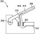
升降机构114和机器人臂120可以包括在机器人100内输送电力、传输电信号和循环流体(气体和/或液体)的装置。控制系统(电力输送和电信号传输)和增强散热(流体循环)可能需要这些布置。在图3A中,在300处示意性地示出了可以促进通过旋转接头耦接的部件之间的功率输送、信号传输和/或流体循环的示例布置,并且将其称为“布置300”。The
如图3A所示,波纹管304可用于连接由旋转接头306耦接的部件的内部容积,以提供用于一个或多个缆线和/或一个或多个软管的通道308。成形引导件310可用于约束一个或多个缆线和/或一个或多个软管,并防止一个或多个缆线和/或一个或多个软管摩擦波纹管304和其它部件。As shown in Figure 3A, bellows 304 may be used to connect the interior volumes of components coupled by
在图3A的示例结构300中,波纹管304的内部容积可以处于与其所连接的机器人部件的内部容积基本相同的压力,该压力可以高于外部真空环境的压力。备选地,为了增加波纹管304的稳定性,该布置可以被重新配置成使得较低压力环境是在波纹管304内部,如图3B中示意性示出的。在图3B中,波纹管304示出为处于其压缩位置。In the
在美国专利No.10,569,430中可以找到可以促进通过旋转接头的功率输送、信号传输和/或流体循环的其它示例布置,该专利通过引用整体并入于此。Other example arrangements that may facilitate power delivery, signal transmission, and/or fluid circulation through a rotary joint can be found in US Patent No. 10,569,430, which is hereby incorporated by reference in its entirety.
另外的装置可以用于在机器人100的固定基部和横移平台112之间传输电力和通信信号。例如,服务环路、电感耦合、电容耦合、光通信链路或射频通信系统可用于此目的。Additional means may be used to transmit power and communication signals between the stationary base of the
如图4A(1)-图4A(3)和图4B(1)-图4B(3)中示意性示出的,机器人100可以沿着固定基部108横移、提升主轴平台116、旋转机器人臂120、并且延伸机器人臂120的每个末端执行器。作为示例,图4A(1)-图4A(3)描绘了相对于固定基部108处于一个位置的机器人100,其中主轴平台116降低并且两个末端执行器160缩回。作为另一示例,图4B(1)-图4B(3)描绘了相对于固定基部108处于另一位置的机器人100,其中主轴平台116升高并且一个末端执行器160延伸。As shown schematically in FIGS. 4A(1)-4A(3) and 4B(1)-4B(3), the
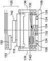
图1A的示例实施例的区别点在于,机器人100的电机和其他部件可以竖直地嵌套或重叠(共享基本上相同的竖直空间(特别是当主轴平台116被降低并且处于收缩位置时,如图5A和图5B所示))。如图5A所示,即使当主轴平台116相对于横移平台112收缩时或当机器人臂120缩回时,电机T的部分也可突出到机器人臂120的第一连杆142中。这减小了机器人100所占据的竖直空间,从而减小了机器人100可以操作的真空室的深度和容积。至少电机A或电机B也可以与处于收缩位置的电机T嵌套,以进一步减小由机器人100占据的竖直空间。The example embodiment of FIG. 1A differs in that the motors and other components of the
在图6-图8中示意性地示出了根据本发明的横移机器人100的备选示例实施例。Alternative exemplary embodiments of a traversing
升降机构114可以包括平衡部件,例如配重或弹簧(例如,螺旋弹簧或扭簧),以减小升降机构114的致动器(电机)上的扭矩或力。在图6中示意性地示出了具有利用处于张紧状态的螺旋弹簧600的平衡特征的示例实施例。备选地,可以使用任何其他合适的平衡特征。The
在图7A中示意性地示出了示例的备选升降机构,在下文中将其称为“升降机构714”。升降机构714可以包括连杆716,连杆716可以分别通过旋转接头720和722被耦接到横移平台112和主轴平台116。升降机构714还可以包括致动器或电机730,致动器或电机730被配置为驱动带732(或皮带或缆索),带732的驱动被配置为保持主轴平台116相对于横移平台112的相同角度取向,例如,以保持主轴平台116基本水平。在该布置中,如图所示,第一滑轮734可以被附接到横移平台112,第二滑轮736可以被附接到主轴平台116。An example alternative lift mechanism is schematically shown in FIG. 7A, hereinafter referred to as "
如图7A所示,连杆716可以由附接到横移平台112的旋转电机RM致动。当旋转电机RM致动连杆716以相对于横移平台112旋转时,主轴平台116相对于横移平台112改变高度。备选地,旋转电机RM可以被附接到主轴平台116。作为另一备选,可以使用线性电机、支柱或任何其它合适的致动装置来致动升降机构714的连杆716。As shown in FIG. 7A , the
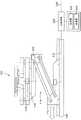
在图7B中以750示意性地示出了另一示例备选升降机构。升降机构750可以包括联动机构,该联动机构可以包括第一连杆754和第二连杆756。第一连杆754可通过第一旋转接头760被耦接到横移平台112,第二连杆756可通过第二旋转接头762被耦接到第一连杆754,并且主轴平台116可通过第三旋转接头764被耦接到第二连杆756。升降机构750的联动机构还可以包括两个带驱动装置、皮带驱动装置或缆索驱动装置,其被配置为保持主轴平台116相对于横移平台112的相同角度取向,例如,以保持主轴平台116基本水平。Another example alternative lift mechanism is shown schematically at 750 in Figure 7B. The
如图7B所示,第一带驱动装置、皮带驱动装置或缆索驱动装置可位于第一连杆754的内部、连接被附接到横移平台112的第一滑轮770和被附接到第二连杆756的第二滑轮772。被附接到横移平台112的第一滑轮770的直径可以是被附接到第二连杆756的第二滑轮772的直径的两倍。第二带驱动装置、皮带驱动装置或缆索驱动装置可以位于第二连杆756的内部、将第二滑轮772连接到主轴平台116上的第三滑轮774。第三滑轮774的直径可以是第二滑轮772的直径的大约两倍并且与第一滑轮770的直径相同或相似。As shown in Figure 7B, a first belt drive, belt drive or cable drive may be located inside the
仍参照图7B,升降机构750的联动机构的第一连杆754可以由横移平台112中或横移平台112上的旋转电机RM致动。在这种布置中,当旋转电机RM致动第一连杆754使得第一连杆754相对于横移平台112旋转时,主轴平台116相对于横移平台112垂直移动。备选地,可使用线性电机、支柱或任何其它合适的致动装置来致动升降机构750。Still referring to FIG. 7B , the
尽管图7B的示例升降机构750示出为具有相同接头到接头长度的两个连杆和圆形滑轮,但是这两个连杆可以具有不相等的接头到接头长度,并且一些或全部滑轮可以是非圆形的。备选地,可以使用任何合适数目的连杆和滑轮类型。由第一连杆754和第二连杆756限定的联动机构可以被布置在横移平台112的一侧或两侧上,并且连接到主轴平台116的一侧或两侧。Although the
作为另一示例,如图7C中示意性示出的,由升降机构750的第一连杆754和第二连杆756限定的联动机构可以被布置在横移平台112的一个或两个面上并且连接到主轴平台116的一个或两个面(与主轴平台116的侧相对)。备选地,升降机构750的第一连杆754和第二连杆756可以被布置在横移平台112和主轴平台116之间的任一合适的位置处。As another example, as schematically shown in FIG. 7C , the linkage defined by the
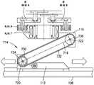
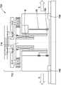
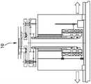
现在参见图7D(1)和图7D(2),示出了具有机器人臂702的示例实施例机器人700的简化截面视图。示例机器人700可以利用一个或多个线性轴承和线性致动系统。在示例机器人700中,主轴平台766可以由一个或多个线性轴承768和线性致动器(例如在导轨或轨道系统(诸如在先前示例中的轨道769)上的力发生器/线圈布置)支撑。主轴平台766可以例如通过合适的Z轴机构26(例如,滚珠丝杠驱动装置、丝杠、带驱动、皮带驱动、线缆驱动、线性电机或任何其它合适的致动装置)上下致动。如图所示,波纹管776可用于容纳真空环境,同时允许主轴平台766上下移动。如在图7E中示意性地展示的,与在此公开的其他示例相比,机器人700的高度可以通过将致动上臂778的电机M重新定位到机器人臂702上来减小。Referring now to FIGS. 7D( 1 ) and 7D( 2 ), simplified cross-sectional views of an
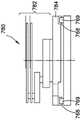
在图7F(1)和图7F(2)中示意性地示出了根据本发明的没有升降机构的横移机器人的示例实施例,并且在下文中将其称为“机器人780”。机器人780包括直接安装在基部784上的机器人臂782,基部784利用一个或多个线性轴承768,线性轴承768被配置为沿着导轨769(或轨道)滑动。机器人780还包括如前述示例实施例中的线性致动系统。An example embodiment of a traverse robot without a lift mechanism according to the present invention is schematically shown in Figures 7F(1) and 7F(2), and is referred to hereinafter as "
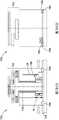
在图7G(1)、图7G(2)、图7G(3)和图7G(4)中提供了所选择的示例实施例与反映现有技术状态的机器人的比较。图7G(1)示出反映现有技术的机器人10的简化截面图;图7G(2)描绘了具有重新定位到机器人臂802的两个电机M的横移机器人800的示例实施例;图7G(3)示出了具有基于联动机构的升降机构的另一示例实施例,例如机器人100;图7G(4)示出了没有升降机构例如机器人780的示例实施例。Comparisons of selected example embodiments with robots reflecting the state of the art are provided in Figures 7G(1), 7G(2), 7G(3), and 7G(4). Figure 7G(1) shows a simplified cross-sectional view of
尽管由单个升降机构支撑的单个主轴平台被示出为上述示例实施例的一部分,但是可以使用任何数目的主轴平台和升降机构,包括没有升降机构。Although a single spindle platform supported by a single lift mechanism is shown as part of the example embodiments described above, any number of spindle platforms and lift mechanisms may be used, including no lift mechanism.
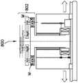
在图8中以1000示意性地示出了示例备选机器人,并且在下文中将其称为“机器人1000”。机器人1000可以由固定基部108支撑,并且可以包括线性引导和致动系统110、横移平台112、升降机构114、主轴平台116和控制系统106,如前述示例中那样。臂1012被安装在主轴平台116上,臂1012具有上臂1014和两个前臂1016,每个前臂承载末端执行器,前臂1016通过同轴旋转接头(称为肘接头1020)被耦接到上臂1014。上臂1014可容纳两个电机(电机A和电机B),每个电机被配置为致动两个前臂1016中的一者。尽管图8示出了具有外转子的配置中的电机A和B,但是电机A和B可以是内转子配置。备选地,可以使用任何合适的电机配置、类型和设计。An example alternative robot is shown schematically at 1000 in FIG. 8 and is hereinafter referred to as "
应当注意的是,在此描述的图中示出的轴承、轴承布置和轴承位置仅用于说明,目的是传达各个部件通常如何相对于彼此被约束。可以使用任何合适的轴承、轴承布置和轴承位置。It should be noted that the bearings, bearing arrangements and bearing locations shown in the figures described herein are for illustration only and are intended to convey how the various components are generally constrained relative to each other. Any suitable bearing, bearing arrangement and bearing location may be used.
尽管通信网络被描述为控制系统的各种部件之间的通信装置,但是可以使用主控制器和控制模块之间的任何其它合适的通信装置,例如无线网络或点对点总线。Although the communication network is described as a means of communication between the various components of the control system, any other suitable means of communication between the main controller and the control module may be used, such as a wireless network or a point-to-point bus.
本文所述的特征可与未决美国专利申请第16/788,993号、第16/788,973号和第15/294,099号中所述的特征一起使用,所述专利申请通过引用全文并入本文。The features described herein may be used in conjunction with features described in pending US patent application Ser. Nos. 16/788,993, 16/788,973, and 15/294,099, which are incorporated herein by reference in their entirety.
在一个示例实施例中,一种装置包括主轴平台;横移平台,该横移平台被配置为在第一方向上移动;升降系统,该升降系统被连接到该主轴平台和该横移平台,该升降系统被配置为在收缩位置与伸展位置之间在第二方向上移动该主轴平台,该第二方向垂直于该第一方向;连接到所述主轴平台的至少一个可移动臂,所述至少一个可移动臂包括连接到所述主轴平台的第一连杆、连接到所述第一连杆的第二连杆和连接到所述第二连杆的第三连杆,以及连接到所述主轴平台并且被配置为引起所述第一连杆旋转的至少一个第一致动器,以及在所述至少一个可移动臂中并且被配置为引起所述第二连杆旋转的至少一个第二致动器。第一致动器从主轴平台延伸到第一连杆中以占据主轴平台和第一连杆的组合厚度。In one example embodiment, an apparatus includes a spindle platform; a traverse platform configured to move in a first direction; a lift system connected to the spindle platform and the traverse platform, The lift system is configured to move the spindle platform in a second direction between a retracted position and an extended position, the second direction being perpendicular to the first direction; at least one movable arm connected to the spindle platform, the At least one movable arm includes a first link connected to the spindle platform, a second link connected to the first link, and a third link connected to the second link, and connected to the at least one first actuator in the spindle platform and configured to cause rotation of the first link, and at least one first actuator in the at least one movable arm and configured to cause rotation of the second link Two actuators. The first actuator extends from the spindle platform into the first link to occupy the combined thickness of the spindle platform and the first link.
该至少一个第一致动器和该至少一个第二致动器可以被配置为在竖直方向上重叠。第一致动器可以被配置为与第二致动器嵌套。该装置还可以包括在横移平台的线性引导系统,该线性引导系统被配置为约束横移平台在线性方向上的运动。线性引导系统可以包括在横移平台的至少一个线性轴承,该至少一个线性轴承被配置为轨道并在轨道上滑动。该装置还可以包括在横移平台的线性致动系统,该线性致动系统被配置为在线性方向上移动横移平台。线性致动系统可以包括线性致动器和至少一个位置传感器。该线性致动器可以包括具有至少一个线圈的永磁电机,该至少一个线圈被配置为磁性地接合一个轨道。所述至少一个位置传感器可以位于该横移平台并且可以被配置为使用一个控制器沿着该线性方向进行控制。升降系统可以包括至少一个连杆,该连杆在横向平台和主轴平台之间延伸并可相对于横向平台和主轴平台旋转。该至少一个联动机构可以使用旋转致动器在横移平台旋转。可使用控制器来控制旋转致动器,以将主轴平台保持在相对于横移平台基本水平的位置。升降系统还可以包括平衡弹簧。The at least one first actuator and the at least one second actuator may be configured to overlap vertically. The first actuator may be configured to nest with the second actuator. The apparatus may also include a linear guidance system at the traverse platform configured to constrain movement of the traverse platform in a linear direction. The linear guide system may include at least one linear bearing on the traverse platform, the at least one linear bearing being configured as a track and sliding on the track. The apparatus may also include a linear actuation system at the traverse platform, the linear actuation system being configured to move the traverse platform in a linear direction. The linear actuation system may include a linear actuator and at least one position sensor. The linear actuator may include a permanent magnet motor having at least one coil configured to magnetically engage a track. The at least one position sensor can be located on the traverse platform and can be configured to be controlled along the linear direction using a controller. The lift system may include at least one link extending between the transverse platform and the spindle platform and rotatable relative to the transverse platform and the spindle platform. The at least one linkage can be rotated on the traverse platform using a rotary actuator. A controller may be used to control the rotary actuator to maintain the spindle stage in a substantially horizontal position relative to the traverse stage. The lift system may also include a balance spring.
在另一个示例实施例中,一种方法包括:提供被配置为在第一方向上移动的横移平台;提供主轴平台;提供连接到所述主轴平台和所述横移平台的升降系统,所述升降系统被配置为使所述主轴平台在第二方向上在收缩位置和伸展位置之间移动,所述第二方向垂直于所述第一方向;以及提供连接到所述主轴平台的至少一个可移动臂,所述至少一个可移动臂包括连接到所述主轴平台的第一连杆、连接到所述第一连杆的第二连杆,以及连接到所述第二连杆的第三连杆;提供至少一个第一致动器,该第一致动器连接到该主轴平台并且被配置为致使该第一连杆旋转,并且在该至少一个可移动臂中提供至少一个第二致动器并且被配置为致使该第二连杆旋转。第一致动器从主轴平台延伸到第一连杆中以占据主轴平台和第一连杆的组合厚度。In another example embodiment, a method includes: providing a traverse platform configured to move in a first direction; providing a spindle platform; providing a lift system coupled to the spindle platform and the traverse platform, the the lift system is configured to move the spindle platform between a retracted position and an extended position in a second direction, the second direction being perpendicular to the first direction; and providing at least one connection to the spindle platform a movable arm, the at least one movable arm including a first link connected to the spindle platform, a second link connected to the first link, and a third link connected to the second link a link; providing at least one first actuator connected to the spindle platform and configured to cause rotation of the first link, and providing at least one second actuator in the at least one movable arm the actuator and is configured to cause the second link to rotate. The first actuator extends from the spindle platform into the first link to occupy the combined thickness of the spindle platform and the first link.
该至少一个第一致动器和该至少一个第二致动器可以被配置为在竖直方向上重叠。该方法还可以包括在往复横移平台设置线性引导系统,该线性引导系统被配置为约束往复横移平台在线性方向上的运动。该方法还可以包括在横移平台设置线性致动系统,该线性致动系统被配置为在线性方向上移动横移平台。该方法还可以包括使用位置传感器和控制器来控制横移平台在第一方向上的运动。该方法还可以包括使用控制器来控制主轴平台在第二方向上的运动。The at least one first actuator and the at least one second actuator may be configured to overlap vertically. The method may also include disposing a linear guide system on the reciprocating traverse platform, the linear guide system being configured to constrain movement of the reciprocating traverse platform in a linear direction. The method may also include disposing a linear actuation system on the traverse platform, the linear actuation system being configured to move the traverse platform in a linear direction. The method may also include using the position sensor and the controller to control movement of the traverse platform in the first direction. The method may also include using the controller to control movement of the spindle stage in the second direction.
在另一示例实施例中,一种装置包括至少一个处理器;以及包括计算机程序代码的至少一个非暂态存储器,该至少一个存储器和该计算机程序代码被配置为与该至少一个处理器一起致使该装置至少执行:在第一方向上移动横移平台;操作连接到所述横移平台和主轴平台的升降系统,以在收缩位置和伸展位置之间在第二方向上移动所述主轴平台,所述第二方向垂直于所述第一方向;操作连接到所述主轴平台的至少一个可移动臂,所述至少一个可移动臂包括连接到所述主轴平台的第一连杆、连接到所述第一连杆的第二连杆,以及连接到所述第二连杆的第三连杆;以及操作至少一个第一致动器装置和至少一个第二致动器装置,所述第一致动器装置连接到所述主轴平台并且被配置为引起所述第一连杆的旋转,所述第二致动器装置在所述至少一个可移动臂中并且被配置为引起所述第二连杆的旋转。第一致动器装置从主轴平台延伸到第一连杆中以占据主轴平台和第一连杆的组合厚度。In another example embodiment, an apparatus includes at least one processor; and at least one non-transitory memory including computer program code, the at least one memory and the computer program code configured to, with the at least one processor, cause The apparatus performs at least: moving a traverse platform in a first direction; operating a lift system connected to said traverse platform and a spindle platform to move said spindle platform in a second direction between a retracted position and an extended position, the second direction is perpendicular to the first direction; at least one movable arm operatively connected to the spindle platform, the at least one movable arm including a first link connected to the spindle platform, connected to the spindle platform a second link of the first link, and a third link connected to the second link; and operating at least one first actuator device and at least one second actuator device, the first An actuator arrangement is connected to the spindle platform and is configured to cause rotation of the first link, the second actuator arrangement is in the at least one movable arm and is configured to cause the second link Rotation of the connecting rod. The first actuator arrangement extends from the spindle platform into the first link to occupy the combined thickness of the spindle platform and the first link.
该装置还可以使第一致动器装置与第二致动器装置嵌套。在第一方向上移动横移平台可以包括使用线性驱动系统沿轨道移动横移平台。使用线性驱动系统沿着轨道移动横移平台可以包括沿磁轨操作具有线圈布置的永磁电机。所述装置还可以包括使用所述至少一个处理器和所述至少一个非暂态存储器以及所述横移平台的位置传感器来感测所述横移平台的位置。该装置还可以包括使用具有升降系统的至少一个处理器和至少一个非暂态存储器,以使主轴平台相对于调平主轴平台。The device may also nest the first actuator device with the second actuator device. Moving the traverse platform in the first direction may include moving the traverse platform along the track using a linear drive system. Using a linear drive system to move the traverse platform along the track may include operating a permanent magnet motor with a coil arrangement along the magnetic track. The apparatus may also include sensing the position of the traverse platform using the at least one processor and the at least one non-transitory memory and a position sensor of the traverse platform. The apparatus may also include using at least one processor and at least one non-transitory memory with a lift system to level the spindle platform relative to the spindle platform.
在另一个示例实施例中,一种装置包括被配置为在第一方向上移动的横移平台;主轴平台,所述主轴平台具有第一致动器和连接到所述第一致动器的第一控制器;连接到所述主轴平台的至少一个可移动臂,所述至少一个可移动臂包括连接到所述第一致动器的第一连杆和连接到所述第一连杆的至少一个第二连杆,所述第二连杆包括至少一个第二致动器并且由所述至少一个可移动臂上的第二控制器控制,所述至少一个第一致动器被配置为引起所述第一连杆的旋转,并且所述至少一个第二致动器被配置为引起所述第二连杆的旋转;升降系统,所述升降系统连接到所述主轴平台和所述横向平台,所述升降系统被配置为在收缩位置和伸展位置之间在第二方向上移动所述主轴平台,所述第二方向垂直于所述第一方向,所述升降系统具有在所述横向平台的第三致动器和连接到所述第三致动器的第三控制器。第一致动器从主轴平台延伸到第一连杆中以占据主轴平台和第一连杆的组合厚度。In another example embodiment, an apparatus includes a traverse stage configured to move in a first direction; a spindle stage having a first actuator and a traverse stage connected to the first actuator a first controller; at least one movable arm connected to the spindle platform, the at least one movable arm including a first link connected to the first actuator and a first link connected to the first link at least one second link including at least one second actuator and controlled by a second controller on the at least one movable arm, the at least one first actuator configured to causing rotation of the first link and the at least one second actuator configured to cause rotation of the second link; a lift system connected to the spindle platform and the transverse a platform, the lift system configured to move the spindle platform in a second direction between a retracted position and an extended position, the second direction being perpendicular to the first direction, the lift system having an orientation in the lateral direction a third actuator of the platform and a third controller connected to the third actuator. The first actuator extends from the spindle platform into the first link to occupy the combined thickness of the spindle platform and the first link.
第一致动器可以与至少一个第二致动器嵌套。第一控制器、第二控制器和第三控制器可以通过通信网络由主控制器来协调。主控制器可以位于横移平台。主控制器可以位于横移平台的外部。横移平台可以被配置为沿直线轴承和轨道系统在第一方向上移动。该装置还可以包括磁体和线圈的系统,该系统被配置为在第一方向上移动横移平台。The first actuator may be nested with at least one second actuator. The first controller, the second controller and the third controller may be coordinated by the main controller through a communication network. The main controller may be located on the traverse platform. The main controller can be located outside the traverse platform. The traverse platform may be configured to move in a first direction along the linear bearing and rail system. The apparatus may also include a system of magnets and coils configured to move the traverse platform in the first direction.
应当理解,前面的描述仅仅是说明性的。本领域技术人员可以设计各种替换和修改。例如,来自上述不同实施例的特征可以选择性地组合到新的实施例中。因此,本说明书旨在包括落入所附权利要求范围内的所有这些替换、修改和变化。It should be understood that the foregoing description is illustrative only. Various alternatives and modifications can be devised by those skilled in the art. For example, features from different embodiments described above may be selectively combined into new embodiments. Accordingly, this specification is intended to cover all such substitutions, modifications and variations that fall within the scope of the appended claims.
Claims (32)
Applications Claiming Priority (3)
| Application Number | Priority Date | Filing Date | Title |
|---|---|---|---|
| US202062983846P | 2020-03-02 | 2020-03-02 | |
| US62/983,846 | 2020-03-02 | ||
| PCT/US2021/020381WO2021178348A1 (en) | 2020-03-02 | 2021-03-02 | Compact traversing robot |
Publications (1)
| Publication Number | Publication Date |
|---|---|
| CN115210046Atrue CN115210046A (en) | 2022-10-18 |
Family
ID=77463385
Family Applications (1)
| Application Number | Title | Priority Date | Filing Date |
|---|---|---|---|
| CN202180018357.0APendingCN115210046A (en) | 2020-03-02 | 2021-03-02 | Compact type transverse moving robot |
Country Status (5)
| Country | Link |
|---|---|
| US (2) | US12128558B2 (en) |
| JP (2) | JP2023518164A (en) |
| KR (1) | KR20230002355A (en) |
| CN (1) | CN115210046A (en) |
| WO (1) | WO2021178348A1 (en) |
Families Citing this family (3)
| Publication number | Priority date | Publication date | Assignee | Title |
|---|---|---|---|---|
| JP7425701B2 (en)* | 2020-09-16 | 2024-01-31 | 芝浦メカトロニクス株式会社 | Board transfer device |
| JP2025503951A (en)* | 2022-01-27 | 2025-02-06 | パーシモン テクノロジーズ コーポレイション | Traverse robot with multiple end effectors |
| CN115805583B (en)* | 2022-12-28 | 2025-02-07 | 天津理工大学 | Parallel robot |
Citations (6)
| Publication number | Priority date | Publication date | Assignee | Title |
|---|---|---|---|---|
| KR20120067488A (en)* | 2010-12-16 | 2012-06-26 | 미래산업 주식회사 | Linear motor and apparatus for transferring substrate using the same |
| CN103430296A (en)* | 2010-09-15 | 2013-12-04 | 应用材料公司 | Low profile dual arm vacuum robot |
| CN103817706A (en)* | 2012-11-16 | 2014-05-28 | 株式会社安川电机 | Robot arm, robot and robot operating method |
| CN104428884A (en)* | 2012-07-05 | 2015-03-18 | 应用材料公司 | Boom drive device, multi-arm robot device, electronic device handling system, and method for transferring substrates in an electronic device manufacturing system |
| CN204508205U (en)* | 2015-03-28 | 2015-07-29 | 苏州荣威工贸有限公司 | A kind of two-way transfer robot of two bars based on parallel principle |
| CN110116898A (en)* | 2018-02-05 | 2019-08-13 | 金宝电子印第安纳公司 | The robot moved with vertically-oriented articulated jib |
Family Cites Families (23)
| Publication number | Priority date | Publication date | Assignee | Title |
|---|---|---|---|---|
| US4678952A (en)* | 1985-08-13 | 1987-07-07 | Intelledex Incorporated | Sealed joint for a robot and the like |
| JPH11238779A (en)* | 1998-02-23 | 1999-08-31 | Mecs Corp | Thin-type substrate carrying multiple joint robot |
| JP2007015863A (en)* | 1998-03-25 | 2007-01-25 | Hitachi Plant Technologies Ltd | Conveying apparatus and manufacturing method |
| JP4509411B2 (en)* | 2001-03-26 | 2010-07-21 | 株式会社ディスコ | Loading / unloading device |
| JP2003080480A (en)* | 2001-09-07 | 2003-03-18 | Tatsumo Kk | Industrial robot |
| JP4389424B2 (en)* | 2001-12-25 | 2009-12-24 | 東京エレクトロン株式会社 | To-be-processed object conveyance mechanism and processing system |
| JP4277100B2 (en)* | 2002-11-14 | 2009-06-10 | 東京エレクトロン株式会社 | Reference position correction apparatus and reference position correction method for transport mechanism |
| CN1981371B (en)* | 2004-07-09 | 2010-05-05 | 日商乐华股份有限公司 | Drive source and transportation robot |
| US8573919B2 (en)* | 2005-07-11 | 2013-11-05 | Brooks Automation, Inc. | Substrate transport apparatus |
| US8701519B2 (en)* | 2006-06-28 | 2014-04-22 | Genmark Automation, Inc. | Robot with belt-drive system |
| JP5016302B2 (en)* | 2006-12-01 | 2012-09-05 | 日本電産サンキョー株式会社 | Arm drive device and industrial robot |
| KR20180128987A (en) | 2011-09-16 | 2018-12-04 | 퍼시몬 테크놀로지스 코포레이션 | An apparatus for moving substrates |
| JP2013074145A (en)* | 2011-09-28 | 2013-04-22 | Sinfonia Technology Co Ltd | Vacuum processing apparatus |
| JP2014078600A (en)* | 2012-10-10 | 2014-05-01 | Sumitomo Heavy Ind Ltd | Deposition apparatus |
| JP5532110B2 (en)* | 2012-11-16 | 2014-06-25 | 株式会社安川電機 | Substrate transfer robot and substrate transfer method |
| US9149936B2 (en) | 2013-01-18 | 2015-10-06 | Persimmon Technologies, Corp. | Robot having arm with unequal link lengths |
| US10224232B2 (en) | 2013-01-18 | 2019-03-05 | Persimmon Technologies Corporation | Robot having two arms with unequal link lengths |
| CN117621011A (en)* | 2015-02-06 | 2024-03-01 | 柿子技术公司 | Robot with arms of unequal link lengths |
| GB2538714A (en)* | 2015-05-25 | 2016-11-30 | Robotical Ltd | Robot Leg |
| US10580682B2 (en)* | 2017-02-15 | 2020-03-03 | Persimmon Technologies, Corp. | Material-handling robot with multiple end-effectors |
| US10549420B2 (en)* | 2018-03-15 | 2020-02-04 | Kimball Electronics Indiana, Inc. | Over and under linear axis robot |
| US11964831B2 (en) | 2019-02-14 | 2024-04-23 | Persimmon Technologies Corporation | Magnetically guided material handling robot |
| CN119115972A (en) | 2019-02-14 | 2024-12-13 | 柿子技术公司 | Modular material handling robotic platform |
- 2021
- 2021-03-02CNCN202180018357.0Apatent/CN115210046A/enactivePending
- 2021-03-02JPJP2022551540Apatent/JP2023518164A/enactivePending
- 2021-03-02USUS17/189,381patent/US12128558B2/enactiveActive
- 2021-03-02KRKR1020227034326Apatent/KR20230002355A/enactivePending
- 2021-03-02WOPCT/US2021/020381patent/WO2021178348A1/ennot_activeCeased
- 2024
- 2024-09-23USUS18/893,106patent/US20250010462A1/enactivePending
- 2025
- 2025-04-14JPJP2025066110Apatent/JP2025103039A/enactivePending
Patent Citations (6)
| Publication number | Priority date | Publication date | Assignee | Title |
|---|---|---|---|---|
| CN103430296A (en)* | 2010-09-15 | 2013-12-04 | 应用材料公司 | Low profile dual arm vacuum robot |
| KR20120067488A (en)* | 2010-12-16 | 2012-06-26 | 미래산업 주식회사 | Linear motor and apparatus for transferring substrate using the same |
| CN104428884A (en)* | 2012-07-05 | 2015-03-18 | 应用材料公司 | Boom drive device, multi-arm robot device, electronic device handling system, and method for transferring substrates in an electronic device manufacturing system |
| CN103817706A (en)* | 2012-11-16 | 2014-05-28 | 株式会社安川电机 | Robot arm, robot and robot operating method |
| CN204508205U (en)* | 2015-03-28 | 2015-07-29 | 苏州荣威工贸有限公司 | A kind of two-way transfer robot of two bars based on parallel principle |
| CN110116898A (en)* | 2018-02-05 | 2019-08-13 | 金宝电子印第安纳公司 | The robot moved with vertically-oriented articulated jib |
Also Published As
| Publication number | Publication date |
|---|---|
| US12128558B2 (en) | 2024-10-29 |
| JP2023518164A (en) | 2023-04-28 |
| KR20230002355A (en) | 2023-01-05 |
| WO2021178348A9 (en) | 2021-12-30 |
| JP2025103039A (en) | 2025-07-08 |
| US20210268641A1 (en) | 2021-09-02 |
| US20250010462A1 (en) | 2025-01-09 |
| WO2021178348A1 (en) | 2021-09-10 |
Similar Documents
| Publication | Publication Date | Title |
|---|---|---|
| US20250010462A1 (en) | Compact Traversing Robot | |
| US11996316B2 (en) | Robot having arm with parallel paths | |
| JP7217718B2 (en) | Robotic and wireless data coupling | |
| JP2011199121A (en) | Conveying apparatus | |
| KR102314361B1 (en) | Robot for transferring substrate | |
| US12350821B2 (en) | Vacuum-environment robot with distributed actuators | |
| KR20000042618A (en) | Robot of cylindrical coordinates | |
| TW200536689A (en) | Carrying device, method of controlling the same, and vacuum processing device | |
| JP2024510251A (en) | Distributed architecture robot with multiple linkages | |
| JPWO2021178348A5 (en) | ||
| US12083666B2 (en) | Traversing robot with multiple end effectors | |
| KR20230078686A (en) | Material-handling robot with magnetically guided end-effectors |
Legal Events
| Date | Code | Title | Description |
|---|---|---|---|
| PB01 | Publication | ||
| PB01 | Publication | ||
| SE01 | Entry into force of request for substantive examination | ||
| SE01 | Entry into force of request for substantive examination |