CN115205369A - Atmospheric turbulence resistant lamp target image displacement extraction algorithm - Google Patents
Atmospheric turbulence resistant lamp target image displacement extraction algorithmDownload PDFInfo
- Publication number
- CN115205369A CN115205369ACN202210931549.7ACN202210931549ACN115205369ACN 115205369 ACN115205369 ACN 115205369ACN 202210931549 ACN202210931549 ACN 202210931549ACN 115205369 ACN115205369 ACN 115205369A
- Authority
- CN
- China
- Prior art keywords
- window
- displacement
- centroid
- lamp target
- extraction algorithm
- Prior art date
- Legal status (The legal status is an assumption and is not a legal conclusion. Google has not performed a legal analysis and makes no representation as to the accuracy of the status listed.)
- Granted
Links
Images


Classifications
- G—PHYSICS
- G06—COMPUTING OR CALCULATING; COUNTING
- G06T—IMAGE DATA PROCESSING OR GENERATION, IN GENERAL
- G06T7/00—Image analysis
- G06T7/60—Analysis of geometric attributes
- G06T7/66—Analysis of geometric attributes of image moments or centre of gravity
- G—PHYSICS
- G06—COMPUTING OR CALCULATING; COUNTING
- G06F—ELECTRIC DIGITAL DATA PROCESSING
- G06F17/00—Digital computing or data processing equipment or methods, specially adapted for specific functions
- G06F17/10—Complex mathematical operations
- G—PHYSICS
- G06—COMPUTING OR CALCULATING; COUNTING
- G06N—COMPUTING ARRANGEMENTS BASED ON SPECIFIC COMPUTATIONAL MODELS
- G06N20/00—Machine learning
- G06N20/10—Machine learning using kernel methods, e.g. support vector machines [SVM]
- G—PHYSICS
- G06—COMPUTING OR CALCULATING; COUNTING
- G06T—IMAGE DATA PROCESSING OR GENERATION, IN GENERAL
- G06T3/00—Geometric image transformations in the plane of the image
- G06T3/04—Context-preserving transformations, e.g. by using an importance map
- Y—GENERAL TAGGING OF NEW TECHNOLOGICAL DEVELOPMENTS; GENERAL TAGGING OF CROSS-SECTIONAL TECHNOLOGIES SPANNING OVER SEVERAL SECTIONS OF THE IPC; TECHNICAL SUBJECTS COVERED BY FORMER USPC CROSS-REFERENCE ART COLLECTIONS [XRACs] AND DIGESTS
- Y02—TECHNOLOGIES OR APPLICATIONS FOR MITIGATION OR ADAPTATION AGAINST CLIMATE CHANGE
- Y02A—TECHNOLOGIES FOR ADAPTATION TO CLIMATE CHANGE
- Y02A90/00—Technologies having an indirect contribution to adaptation to climate change
- Y02A90/10—Information and communication technologies [ICT] supporting adaptation to climate change, e.g. for weather forecasting or climate simulation
Landscapes
- Engineering & Computer Science (AREA)
- Physics & Mathematics (AREA)
- Theoretical Computer Science (AREA)
- General Physics & Mathematics (AREA)
- Software Systems (AREA)
- Mathematical Physics (AREA)
- Data Mining & Analysis (AREA)
- Computer Vision & Pattern Recognition (AREA)
- General Engineering & Computer Science (AREA)
- Medical Informatics (AREA)
- Geometry (AREA)
- Computing Systems (AREA)
- Evolutionary Computation (AREA)
- Artificial Intelligence (AREA)
- Algebra (AREA)
- Computational Mathematics (AREA)
- Mathematical Analysis (AREA)
- Mathematical Optimization (AREA)
- Pure & Applied Mathematics (AREA)
- Databases & Information Systems (AREA)
- Length Measuring Devices By Optical Means (AREA)
Abstract
Description
Translated fromChinese技术领域technical field
本发明涉及光学图像测量技术领域,具体地说,是一种抗大气湍流的灯靶图像位移提取算法。The invention relates to the technical field of optical image measurement, in particular to a lamp target image displacement extraction algorithm against atmospheric turbulence.
背景技术Background technique
大气扰动对诸如形貌、位移、以及速度等精密光学测量结果的精度折损已经被证实。在精密光测领域,目前常采用图像复原、信号滤波法基本不涉及光学原理,对于本研究拟进行的挠度定量测量,消扰效果有限。而通过相机系统设计的修正方法不适用于单相机测量的应用。在军事领域广泛采用的湍流图像处理方法,局限于目标的检测,还不能直接应用于位移测量。Mahrt等指出大气扰动会引起目标成像模糊和畸变,由此增加了目标中心定位误差。The impairment of precision optical measurements such as topography, displacement, and velocity by atmospheric disturbances has been demonstrated. In the field of precision optical measurement, image restoration and signal filtering methods are often used at present, which basically do not involve optical principles. For the quantitative measurement of deflection to be carried out in this study, the interference elimination effect is limited. The correction method designed by the camera system is not suitable for the application of single-camera measurement. The turbulent image processing method widely used in the military field is limited to the detection of the target and cannot be directly applied to the displacement measurement. Mahrt et al. pointed out that atmospheric disturbance will cause blur and distortion of target imaging, thereby increasing the error of target center positioning.
目前,常用的中心定位算法主要有质心法、形心法、拟合法、最小二乘法等。考虑大气扰动的中心定位算法的研究主要适用于人为设计或者结构表面固有的灰度分布较为均匀的目标,不适用于光源目标定位算法的抗大气扰动性能提升,Yang等从图像处理角度提出的计算窗口自适应确定方法,以及在红外目标辐射强度测量领域,提出的基于正态分布“3σ”原则的真实成像区域鉴别方法,有效抑制了模糊退化对计算区域确定的干扰。但上述研究均只适用于圆形或者矩形等形状规则的光源目标,而且忽略可能发生的成像畸变的影响。此外,单一的定位算法难以保障畸变情况下的中心检测准确性。针对后者,加权定位方法应运而生。由于这种方法对权值的确定要求很高,而受大气扰动影响后的畸变目标中心同其特征间的内在联系机制又较为复杂,Wang等提出基于BPNN的目标中心加权定位方法,对基于多种算法得到的中心检测结果进行加权处理。但该研究仍存在两方面的不足:一方面,BPNN是基于经验风险最小化准则,存在“过拟合”问题,模型的推广能力较差,网络拓扑结构难确定、易陷入局部最优等缺陷。而LS-SVM是采用最小二乘线性系统误差平方和作为损失函数,用等式约束代替不等式约束,使求解过程变成解一组等式方程,避免了求解费时的二次规划问题,训练速度大大加快,而且LS-SVM不再需要预先给定拟合精度,且具有更高的预测精度;另一方面,已有的基于BPNN的加权定位方法仍然沿用固定阈值确定成像区域,忽略大气扰动引起的成像区域变化对定位结果的影响。At present, the commonly used center positioning algorithms mainly include the centroid method, the centroid method, the fitting method, and the least squares method. The research on the center positioning algorithm considering atmospheric disturbance is mainly suitable for the target with a relatively uniform gray distribution inherent in the artificial design or the surface of the structure. It is not suitable for the improvement of the anti-atmospheric disturbance performance of the light source target positioning algorithm. The calculation proposed by Yang et al. The window adaptive determination method and the real imaging area identification method based on the "3σ" principle of normal distribution proposed in the field of infrared target radiation intensity measurement can effectively suppress the interference of blur degradation on the determination of the calculation area. However, the above studies are only applicable to light sources with regular shapes such as circles or rectangles, and ignore the influence of possible imaging distortion. In addition, it is difficult for a single localization algorithm to guarantee the accuracy of center detection in the case of distortion. In response to the latter, the weighted positioning method came into being. Since this method has high requirements for the determination of weights, and the internal connection mechanism between the distorted target center and its features after being affected by atmospheric disturbance is more complicated, Wang et al. The center detection results obtained by each algorithm are weighted. However, there are still two shortcomings in this research: on the one hand, BPNN is based on the empirical risk minimization criterion, which has the problem of "overfitting", the model's generalization ability is poor, the network topology is difficult to determine, and it is easy to fall into local optimum. The LS-SVM uses the least squares linear system error sum of squares as the loss function, and replaces the inequality constraints with equality constraints, so that the solution process becomes a set of equation equations, avoiding the time-consuming quadratic programming problem, and the training speed It is greatly accelerated, and LS-SVM no longer needs to pre-specify the fitting accuracy, and has higher prediction accuracy; on the other hand, the existing weighted localization methods based on BPNN still use a fixed threshold to determine the imaging area, ignoring the atmospheric disturbance caused by The effect of changes in the imaging area on the localization results.
发明内容SUMMARY OF THE INVENTION
本发明的目的是提出一种抗大气湍流的灯靶图像位移提取算法,从大气湍流对灯靶成像的影响效果入手,分别从有效计算窗口选择和加权定位入手,减少成像模糊和畸变的影响。The purpose of the present invention is to propose a lamp target image displacement extraction algorithm against atmospheric turbulence, starting from the effect of atmospheric turbulence on lamp target imaging, starting from effective calculation window selection and weighted positioning, to reduce the influence of imaging blur and distortion.
本发明采用的技术方案如下:The technical scheme adopted in the present invention is as follows:
一种抗大气湍流的灯靶图像位移提取算法,包括如下步骤:A light target image displacement extraction algorithm against atmospheric turbulence, comprising the following steps:
S1:在初始参考图中确定灯靶目标的粗略计算窗口M×N,并计算该区域的能量E,如公式(1):g(x,y)表示像素坐标(x,y)处的灰度。S1: Determine the rough calculation window M×N of the light target target in the initial reference map, and calculate the energy E of this area, such as formula (1): g(x, y) represents the gray at the pixel coordinates (x, y) Spend.

S2:在粗选窗口提取能量集中区域。该区域需要同时满足公式(2)和公式(3)的条件,即当灰度g(x,y)大于阈值gT时,计算其能量,需要满足能量大于总能量的η倍,若不满足,需要重新调整gT的值直到同时满足这两个条件。其中,η表示CCD相机弥散斑能量集中度(η=80%)。gT表示满足能量集中度后的新的窗口判定阈值。S2: Extract the energy concentration area in the rough selection window. This area needs to meet the conditions of formula (2) and formula (3) at the same time, that is, when the gray level g(x, y) is greater than the threshold value gT , to calculate its energy, the energy needs to be greater than η times the total energy, if not , the value of gT needs to be readjusted until both conditions are met. Among them, η represents the energy concentration of the CCD camera speckle (η=80%). gT represents the new window judgment threshold after the energy concentration degree is satisfied.


S3:在有效窗口内进行形心和灰度平方质心检测。形心计算采用公式(4),这里的灰度是二值化灰度。S3: Perform centroid and gray-square centroid detection within the effective window. The centroid is calculated using formula (4), where the grayscale is a binarized grayscale.

对于灰度平方质心计算,需要采用像素自身的灰度值。为了降低噪声的影响,需要对提取的有效窗口内的像元进行灰度优化,具体计算过程如式(5)所示。灰度平方质心计算采用公式(6)。For the gray square centroid calculation, the gray value of the pixel itself needs to be used. In order to reduce the influence of noise, it is necessary to perform grayscale optimization on the pixels in the extracted effective window, and the specific calculation process is shown in formula (5). The gray square centroid is calculated using formula (6).


S4:确定参考图中灯靶目标的加权中心定位结果。将得到的形心(x1,y1)和灰度平方质心(x2,y2)与真实中心(x0,y0)间的加权关系表示为:S4: Determine the weighted center positioning result of the light target in the reference image. The weighted relationship between the obtained centroid (x1 , y1 ) and gray square centroid (x2 , y2 ) and the true center (x0 , y0 ) is expressed as:

式中,ηi表示两种定位结果的权重。由于在实际测量中,受大气扰动影响后的目标中心检测结果同真实中心位置之间的内在联系机制较为复杂,本发明提出借助最小二乘支持向量机LS-SVM算法的拟合功能来实现该权重的求解。In the formula, ηi represents the weight of the two positioning results. Because in the actual measurement, the internal connection mechanism between the detection result of the target center affected by the atmospheric disturbance and the real center position is relatively complicated, the present invention proposes to use the fitting function of the least squares support vector machine LS-SVM algorithm to achieve this Solving for weights.
S5:在后续变形图中重复S1-S4。但在后续变形图中确定能量集中区域时,需要以“目标成像的集中能量保持不变”为基本假定,调整阈值gT,目的是降低湍流引起有效窗口的波动。继而,在有效窗口内进行后续的加权中心定位。S5: Repeat S1-S4 in subsequent deformation diagrams. However, when determining the energy concentration area in the subsequent deformation map, it is necessary to adjust the threshold gT based on the basic assumption that "the concentrated energy of the target imaging remains unchanged", in order to reduce the fluctuation of the effective window caused by turbulence. Then, the subsequent weighted center positioning is performed within the effective window.
S6:计算中心位移。假定在参考图frame_0中的加权中心定位结果为:(xw0,yw0),在变形图frame_i中的加权中心定位结果为:(xwi,ywi),则位移分量为:S6: Calculate the center displacement. Assuming that the weighted center positioning result in the reference image frame_0 is: (xw0 , yw0 ), and the weighted center positioning result in the deformation image frame_i is: (xwi , ywi ), the displacement component is:

所述S4步骤中,权重值的求解采用的是最小二乘支持向量机方法(LS-SVM)。需要在实际结构位移测量前,预先采集一些现场的稳定灯靶目标的图像,用于LS-SVM的学习。由于在实际结构中,几乎没有完全不动的目标,所以本发明专利,选取在支座或者基础附近的目标,以该目标位移时程的方差最小为目标优化函数:In the step S4, the solution of the weight value adopts the least squares support vector machine method (LS-SVM). Before the actual structural displacement measurement, it is necessary to collect some images of the on-site stable light target for the learning of LS-SVM. Since in the actual structure, there is almost no completely immobile target, the patent of the present invention selects the target near the support or the foundation, and takes the minimum variance of the target displacement time history as the target optimization function:

通过预先学习,得到最优的权重值。近似认为该区域短时间内湍流参数变化很小,所以该权重值可以直接用于后续目标的位移提取。Through pre-learning, the optimal weight value is obtained. It is approximated that the turbulence parameters in this area change very little in a short time, so the weight value can be directly used for the displacement extraction of subsequent targets.
有益效果:与现有方法相比,本发明具有如下优点:可以大幅度削减大气湍流引起的灯靶目标图像位移的监测误差,使得摄影测量技术应用于结构的位移测量时具有更高的精度和抵抗复杂环境的鲁棒性。Beneficial effects: Compared with the existing method, the present invention has the following advantages: the monitoring error of the image displacement of the lamp target caused by atmospheric turbulence can be greatly reduced, so that the photogrammetry technology has higher precision and accuracy when applied to the displacement measurement of the structure. Robustness against complex environments.
附图说明Description of drawings
图1为本发明的灯靶图像位移提取的基本过程图。FIG. 1 is a basic process diagram of the lamp target image displacement extraction according to the present invention.
图2为本发明所提出方法在一斜拉桥位移测量时的LED灯靶图像中心定位示意图。FIG. 2 is a schematic diagram of the center positioning of the LED light target image during displacement measurement of a cable-stayed bridge by the method proposed by the present invention.
图3为本发明的LS-SVM的基本流程图。FIG. 3 is a basic flow chart of the LS-SVM of the present invention.
图4为本发明的实施例的位移计算结果图。FIG. 4 is a diagram of a displacement calculation result according to an embodiment of the present invention.
图5为本发明的算法中心定位准确性提升效果的验真实验的现场:试验设备布置Fig. 5 is the scene of the verification experiment of the improvement effect of the algorithm center positioning accuracy of the present invention: the layout of the test equipment(a)相机布置;(b)位移台与目标;(c)相机视场。(a) Camera arrangement; (b) stage and target; (c) camera field of view.
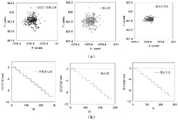
图6为本发明的验证试验结果:(a)不同算法的静止目标定位结果;(b)不同算法的Fig. 6 is the verification test result of the present invention: (a) the stationary target positioning results of different algorithms; (b) the results of different algorithms移动目标定位结果。Moving target positioning results.
具体实施方式Detailed ways
为了加深对本发明的理解,下面将结合附图和实施例对本发明做进一步详细描述,该实施例仅用于解释本发明,并不对本发明的保护范围构成限定。In order to deepen the understanding of the present invention, the present invention will be further described in detail below with reference to the accompanying drawings and embodiments. The embodiments are only used to explain the present invention and do not limit the protection scope of the present invention.
如图1所示,一种抗大气湍流的灯靶图像位移提取算法,包括以下步骤:As shown in Figure 1, a light target image displacement extraction algorithm against atmospheric turbulence includes the following steps:
S1、在初始参考图中确定灯靶目标的粗略计算窗口,并计算该区域的能量;S1. Determine the rough calculation window of the light target target in the initial reference map, and calculate the energy in this area;
S2、在粗选窗口提取能量集中区域;S2. Extract the energy concentration area in the rough selection window;
S3、在有效窗口内进行形心和灰度平方质心检测;S3. Perform centroid and gray square centroid detection within the effective window;
S4、确定参考图中灯靶目标的加权中心定位结果;S4, determine the weighted center positioning result of the light target in the reference picture;
S5、在后续变形图中重复S1-S4;S5. Repeat S1-S4 in subsequent deformation diagrams;
S6、计算中心位移。S6. Calculate the center displacement.
以一斜拉桥的LED灯目标图像位移提取为例,包括如下步骤:Taking the image displacement extraction of the LED light of a cable-stayed bridge as an example, the following steps are included:
S1:在初始参考图中,确定支座位置灯靶目标的粗略计算窗口M×N(图2(a)),并计算该区域的能量E。S1: In the initial reference map, determine the rough calculation window M×N of the light target target at the support position (Figure 2(a)), and calculate the energy E in this area.
S2:在粗选窗口提取能量集中区域(图2(c))。S2: Extract the energy concentration area in the rough selection window (Fig. 2(c)).
S3:在有效窗口内进行形心和灰度平方质心检测。S3: Perform centroid and gray-square centroid detection within the effective window.
S4:将加权定位坐标用得到的形心(x1,y1)和灰度平方质心(x2,y2)与真实中心(x0,y0)间的表示为:S4: The weighted positioning coordinates are expressed between the centroid (x1 , y1 ) and the gray square centroid (x2 , y2 ) and the true center (x0 , y0 ) as:

式中,ηi表示两种定位结果的权重。In the formula, ηi represents the weight of the two positioning results.
S5:在后续时刻中,以确保集中能量不变为准则,调整图像阈值,获得自适应的能量集中区域(即有效计算窗口),并重复S3-S4。S5: In the subsequent moments, to ensure that the concentrated energy remains unchanged, adjust the image threshold to obtain an adaptive energy concentration area (ie, an effective calculation window), and repeat S3-S4.
S6:求解最优权重。基于上述步骤得到各个时刻的稳定目标点的像素位移,以位移方差最小为优化目标函数,借助最小二乘支持向量机LS-SVM算法的拟合最优权重值,流程图如图3所示。S6: Find the optimal weight. Based on the above steps, the pixel displacement of the stable target point at each moment is obtained, the minimum displacement variance is used as the optimal objective function, and the optimal weight value is fitted by the least squares support vector machine LS-SVM algorithm. The flow chart is shown in Figure 3.
S7:对于变形截面位置的灯靶,重复S1-S5,并基于S6得到的权重值带入。得到灯靶的图像位移(图4)。S7: For the lamp target at the deformed section position, repeat S1-S5, and bring in the weight value obtained based on S6. The image displacement of the light target is obtained (Fig. 4).
为了进一步说明所提出方法的优越性,进行了实验验证,如图5所示,试验在校园In order to further illustrate the superiority of the proposed method, experimental verification is carried out, as shown in Fig. 5, the experiment is carried out on campus的林荫大道进行,地面为水泥路面,而且由于是在7月份的夏季,温度高,这都会引起近地面It is carried out on the boulevard, the ground is cement pavement, and because it is summer in July, the temperature is high, which will cause near ground大气扰动的剧烈程度。试验中采用的靶标为60W的850nm红外灯,在镜头前加设带通滤光片The severity of the atmospheric disturbance. The target used in the test is a 60W 850nm infrared lamp, and a bandpass filter is added in front of the lens.可以有效过滤850nm以下自然杂光影响。电动位移台的量程为500mm,精度为0.1mm。It can effectively filter the influence of natural stray light below 850nm. The range of the electric stage is 500mm and the accuracy is 0.1mm.
S1:目标距离相机50米,并保持静止,以2帧每秒的采集频率,连续采集5分钟,采用S1: The target is 50 meters away from the camera, and keeps still, with the acquisition frequency of 2 frames per second, continuous acquisition for 5 minutes, using灰度平方质心法和形心法分别对目标中心的像素坐标进行提取,继而采用LS-SVM方法,以The gray square centroid method and the centroid method extract the pixel coordinates of the target center respectively, and then use the LS-SVM method to加权后的坐标所得到的位移波动方差为零为目标,拟合坐标的权重值结果是:λ1=0.4,λ1=The displacement fluctuation variance obtained by the weighted coordinates is zero as the target, and the result of the weight value of the fitted coordinates is: λ1 =0.4,λ1 =0.6,上述三种中心提取算法的定位结果图6(a)所示。0.6, the positioning results of the above three center extraction algorithms are shown in Figure 6(a).
S2:随后,目标在位移台的控制下以步进1mm进行阶梯式移动。分别采用灰度平方S2: Subsequently, the target moves stepwise with a step of 1 mm under the control of the stage. gray squared质心法、形心法以及加权法计算出目标的竖向位移,结果如图6(b)所示。以位移台的数据为The vertical displacement of the target is calculated by the centroid method, the centroid method and the weighting method, and the results are shown in Figure 6(b). Taking the data of the displacement stage as真实参考值,显然,采用加权定位算法得到的位移测量值具有更好的准确性和稳定性。The true reference value, obviously, the displacement measurement value obtained by using the weighted positioning algorithm has better accuracy and stability.
上述灯靶图像变形测量方法可以有效降低大气湍流引起的灯目标位移测量误差。也有利于其在大桥等结构位移的夜间测量的推广使用The above method for measuring the deformation of the lamp target image can effectively reduce the measurement error of the lamp target displacement caused by atmospheric turbulence. It is also conducive to its popularization and use in nighttime measurement of structural displacements such as bridges.
以上显示和描述了本发明的基本原理、主要特征及优点。本行业的技术人员应该了解,本发明不受上述实施例的限制,上述实施例和说明书中描述的只是说明本发明的原理,在不脱离本发明精神和范围的前提下,本发明还会有各种变化和改进,这些变化和改进都落入要求保护的本发明范围内。本发明要求保护范围由所附的权利要求书及其等效物界定。The foregoing has shown and described the basic principles, main features and advantages of the present invention. Those skilled in the art should understand that the present invention is not limited by the above-mentioned embodiments, and the descriptions in the above-mentioned embodiments and the description are only to illustrate the principle of the present invention. Without departing from the spirit and scope of the present invention, the present invention will have Various changes and modifications fall within the scope of the claimed invention. The claimed scope of the present invention is defined by the appended claims and their equivalents.
Claims (7)


Priority Applications (1)
| Application Number | Priority Date | Filing Date | Title |
|---|---|---|---|
| CN202210931549.7ACN115205369B (en) | 2022-08-03 | 2022-08-03 | Anti-atmospheric turbulence lamp target image displacement extraction algorithm |
Applications Claiming Priority (1)
| Application Number | Priority Date | Filing Date | Title |
|---|---|---|---|
| CN202210931549.7ACN115205369B (en) | 2022-08-03 | 2022-08-03 | Anti-atmospheric turbulence lamp target image displacement extraction algorithm |
Publications (2)
| Publication Number | Publication Date |
|---|---|
| CN115205369Atrue CN115205369A (en) | 2022-10-18 |
| CN115205369B CN115205369B (en) | 2024-04-02 |
Family
ID=83586450
Family Applications (1)
| Application Number | Title | Priority Date | Filing Date |
|---|---|---|---|
| CN202210931549.7AActiveCN115205369B (en) | 2022-08-03 | 2022-08-03 | Anti-atmospheric turbulence lamp target image displacement extraction algorithm |
Country Status (1)
| Country | Link |
|---|---|
| CN (1) | CN115205369B (en) |
Citations (16)
| Publication number | Priority date | Publication date | Assignee | Title |
|---|---|---|---|---|
| US4499597A (en)* | 1982-03-29 | 1985-02-12 | Hughes Aircraft Company | Small-object location utilizing centroid accumulation |
| US4727562A (en)* | 1985-09-16 | 1988-02-23 | General Electric Company | Measurement of scatter in x-ray imaging |
| US5022089A (en)* | 1990-01-19 | 1991-06-04 | Wilson Monti R | Method and apparatus for fast registration using crosshair register marks |
| US20040208385A1 (en)* | 2003-04-18 | 2004-10-21 | Medispectra, Inc. | Methods and apparatus for visually enhancing images |
| US7860344B1 (en)* | 2005-05-06 | 2010-12-28 | Stochastech Corporation | Tracking apparatus and methods using image processing noise reduction |
| CN107610102A (en)* | 2017-08-24 | 2018-01-19 | 东南大学 | A kind of Displacement measuring method based on Tikhonov regularizations |
| CN109035326A (en)* | 2018-06-19 | 2018-12-18 | 北京理工大学 | High-precision location technique based on sub-pix image recognition |
| CN110864587A (en)* | 2019-11-08 | 2020-03-06 | 中国科学院长春光学精密机械与物理研究所 | Seeker aiming positioning method and aiming positioning system |
| CN111050652A (en)* | 2017-09-12 | 2020-04-21 | 皇家飞利浦有限公司 | Spectral (multi-energy) image data for image-guided applications |
| CA3038176A1 (en)* | 2019-03-27 | 2020-09-27 | 4DM Inc. | Object motion mapping from single-pass electro-optical satellite imaging sensors |
| CN112712542A (en)* | 2020-12-25 | 2021-04-27 | 武汉大学 | Foundation cloud picture motion prediction method combining block matching and optical flow method |
| CN112735163A (en)* | 2020-12-25 | 2021-04-30 | 北京百度网讯科技有限公司 | Method for determining static state of target object, road side equipment and cloud control platform |
| CN113192121A (en)* | 2021-04-16 | 2021-07-30 | 西安理工大学 | Light spot center sliding weighting centroid positioning method under atmospheric turbulence |
| US20210383563A1 (en)* | 2021-06-21 | 2021-12-09 | University Of Electronic Science And Technology Of China | Method for quantitatively identifying the defects of large-size composite material based on infrared image sequence |
| CN114108717A (en)* | 2021-12-09 | 2022-03-01 | 上海勘察设计研究院(集团)有限公司 | Foundation pit enclosure top deformation monitoring system and method based on vision measurement |
| CN114166178A (en)* | 2021-12-09 | 2022-03-11 | 上海勘察设计研究院(集团)有限公司 | Real-time deformation monitoring method and system for frame section of tunnel shield machine under construction |
- 2022
- 2022-08-03CNCN202210931549.7Apatent/CN115205369B/enactiveActive
Patent Citations (16)
| Publication number | Priority date | Publication date | Assignee | Title |
|---|---|---|---|---|
| US4499597A (en)* | 1982-03-29 | 1985-02-12 | Hughes Aircraft Company | Small-object location utilizing centroid accumulation |
| US4727562A (en)* | 1985-09-16 | 1988-02-23 | General Electric Company | Measurement of scatter in x-ray imaging |
| US5022089A (en)* | 1990-01-19 | 1991-06-04 | Wilson Monti R | Method and apparatus for fast registration using crosshair register marks |
| US20040208385A1 (en)* | 2003-04-18 | 2004-10-21 | Medispectra, Inc. | Methods and apparatus for visually enhancing images |
| US7860344B1 (en)* | 2005-05-06 | 2010-12-28 | Stochastech Corporation | Tracking apparatus and methods using image processing noise reduction |
| CN107610102A (en)* | 2017-08-24 | 2018-01-19 | 东南大学 | A kind of Displacement measuring method based on Tikhonov regularizations |
| CN111050652A (en)* | 2017-09-12 | 2020-04-21 | 皇家飞利浦有限公司 | Spectral (multi-energy) image data for image-guided applications |
| CN109035326A (en)* | 2018-06-19 | 2018-12-18 | 北京理工大学 | High-precision location technique based on sub-pix image recognition |
| CA3038176A1 (en)* | 2019-03-27 | 2020-09-27 | 4DM Inc. | Object motion mapping from single-pass electro-optical satellite imaging sensors |
| CN110864587A (en)* | 2019-11-08 | 2020-03-06 | 中国科学院长春光学精密机械与物理研究所 | Seeker aiming positioning method and aiming positioning system |
| CN112712542A (en)* | 2020-12-25 | 2021-04-27 | 武汉大学 | Foundation cloud picture motion prediction method combining block matching and optical flow method |
| CN112735163A (en)* | 2020-12-25 | 2021-04-30 | 北京百度网讯科技有限公司 | Method for determining static state of target object, road side equipment and cloud control platform |
| CN113192121A (en)* | 2021-04-16 | 2021-07-30 | 西安理工大学 | Light spot center sliding weighting centroid positioning method under atmospheric turbulence |
| US20210383563A1 (en)* | 2021-06-21 | 2021-12-09 | University Of Electronic Science And Technology Of China | Method for quantitatively identifying the defects of large-size composite material based on infrared image sequence |
| CN114108717A (en)* | 2021-12-09 | 2022-03-01 | 上海勘察设计研究院(集团)有限公司 | Foundation pit enclosure top deformation monitoring system and method based on vision measurement |
| CN114166178A (en)* | 2021-12-09 | 2022-03-11 | 上海勘察设计研究院(集团)有限公司 | Real-time deformation monitoring method and system for frame section of tunnel shield machine under construction |
Non-Patent Citations (2)
| Title |
|---|
| RIBEIRO D, ET AL: "Non-contact measurement of the dynamic displacement of railway bridges using an advanced video-based system", ENGINEERING STRUCTURES, 31 December 2014 (2014-12-31), pages 164 - 180* |
| 于姗姗: "基于相机扰动校正的桥梁结构变形测量方法与应用", 东南大学, 15 May 2022 (2022-05-15), pages 1 - 139* |
Also Published As
| Publication number | Publication date |
|---|---|
| CN115205369B (en) | 2024-04-02 |
Similar Documents
| Publication | Publication Date | Title |
|---|---|---|
| CN107229930B (en) | Intelligent identification method for numerical value of pointer instrument | |
| CN107687819B (en) | A fast and high-accuracy method for sub-pixel extraction of light strip center | |
| CN111914695B (en) | Tidal bore monitoring method based on machine vision | |
| CN115761563A (en) | A Calculation Method and System for River Surface Velocity Based on Optical Flow Calculation | |
| CN113192121B (en) | Light spot center sliding weighted centroid positioning method under atmospheric turbulence | |
| CN114509018A (en) | Full-field real-time bridge deflection measurement method | |
| CN118333985A (en) | Foundation pit slope deformation monitoring method based on multi-source image recognition | |
| CN115471501A (en) | Method and system for online recognition of generator air gap distribution state using machine vision | |
| CN116934808A (en) | River surface flow velocity measurement method based on water surface floater target tracking | |
| CN119470967B (en) | Water area surface flow velocity area monitoring method based on intelligent visual analysis | |
| CN108286948A (en) | A kind of deflection of bridge span detection method based on image procossing | |
| CN114580559A (en) | Speed measuring method based on monocular vision system | |
| CN116563262A (en) | Building crack detection algorithm based on multiple modes | |
| CN115546072B (en) | A method of image distortion correction | |
| CN120147709A (en) | A real-time recognition method for road surface defects based on multimodal fusion of visible light and infrared images | |
| CN115248464A (en) | A high-speed and high-precision infrared target position measurement device based on infrared thermal imaging | |
| CN115205369B (en) | Anti-atmospheric turbulence lamp target image displacement extraction algorithm | |
| CN104408432B (en) | Infrared image target detection method based on histogram modification | |
| CN114926418A (en) | Non-contact measurement method for tension of guyed tower guyed wire of ultra-high voltage transmission line | |
| CN207319290U (en) | One kind interference far field beam test system | |
| CN115861587B (en) | Planar bionic compound eye imaging device and dynamic visual feature extraction method | |
| CN115797411B (en) | A method of using machine vision to identify the deformation of cable trays in hydropower stations online | |
| CN116758149A (en) | Bridge structure displacement detection method based on unmanned aerial vehicle system | |
| CN110796660B (en) | Image definition evaluation method for airport runway | |
| CN115984360A (en) | A method and system for calculating dry beach length based on image processing |
Legal Events
| Date | Code | Title | Description |
|---|---|---|---|
| PB01 | Publication | ||
| PB01 | Publication | ||
| SE01 | Entry into force of request for substantive examination | ||
| SE01 | Entry into force of request for substantive examination | ||
| GR01 | Patent grant | ||
| GR01 | Patent grant |