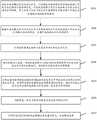
CN115203008A - A test method, device, storage medium and equipment - Google Patents
A test method, device, storage medium and equipmentDownload PDFInfo
- Publication number
- CN115203008A CN115203008ACN202110382456.9ACN202110382456ACN115203008ACN 115203008 ACN115203008 ACN 115203008ACN 202110382456 ACN202110382456 ACN 202110382456ACN 115203008 ACN115203008 ACN 115203008A
- Authority
- CN
- China
- Prior art keywords
- fault
- test
- state
- path
- tested
- Prior art date
- Legal status (The legal status is an assumption and is not a legal conclusion. Google has not performed a legal analysis and makes no representation as to the accuracy of the status listed.)
- Pending
Links
Images


Classifications
- G—PHYSICS
- G06—COMPUTING OR CALCULATING; COUNTING
- G06F—ELECTRIC DIGITAL DATA PROCESSING
- G06F11/00—Error detection; Error correction; Monitoring
- G06F11/36—Prevention of errors by analysis, debugging or testing of software
- G06F11/3668—Testing of software
- G06F11/3672—Test management
- G06F11/3684—Test management for test design, e.g. generating new test cases
- G—PHYSICS
- G06—COMPUTING OR CALCULATING; COUNTING
- G06F—ELECTRIC DIGITAL DATA PROCESSING
- G06F11/00—Error detection; Error correction; Monitoring
- G06F11/36—Prevention of errors by analysis, debugging or testing of software
- G06F11/3668—Testing of software
- G06F11/3672—Test management
- G06F11/3688—Test management for test execution, e.g. scheduling of test suites
- G—PHYSICS
- G06—COMPUTING OR CALCULATING; COUNTING
- G06F—ELECTRIC DIGITAL DATA PROCESSING
- G06F11/00—Error detection; Error correction; Monitoring
- G06F11/36—Prevention of errors by analysis, debugging or testing of software
- G06F11/3668—Testing of software
- G06F11/3672—Test management
- G06F11/3692—Test management for test results analysis
Landscapes
- Engineering & Computer Science (AREA)
- Theoretical Computer Science (AREA)
- Computer Hardware Design (AREA)
- Quality & Reliability (AREA)
- Physics & Mathematics (AREA)
- General Engineering & Computer Science (AREA)
- General Physics & Mathematics (AREA)
- Test And Diagnosis Of Digital Computers (AREA)
Abstract
Description
Translated fromChinese技术领域technical field
本申请涉及计算机技术领域,尤其涉及一种测试方法、装置、存储介质及设备。The present application relates to the field of computer technology, and in particular, to a testing method, apparatus, storage medium and device.
背景技术Background technique
软件故障通常是在软件设计过程中引入的,随着计算机系统复杂程序和性能的提高,不管是面向的应用还是软件系统的复杂程度和规模都迅速提高,而任何编程语言、编程方法以及任何程序员都不能保证在程序设计和编码过程中不引入故障或出现问题,因此对开发的软件系统进行可靠性和容错性测试是非常有必要的。在测试过程中,需要尽可能地提高场景覆盖率,简化测试流程,提高测试效率和测试效果。Software faults are usually introduced in the process of software design. With the improvement of the complex procedures and performance of computer systems, the complexity and scale of both application-oriented and software systems are rapidly increasing, and any programming language, programming method, and any program. No one can guarantee that no faults or problems will be introduced in the process of program design and coding, so it is very necessary to test the reliability and fault tolerance of the developed software system. In the testing process, it is necessary to improve the scene coverage as much as possible, simplify the testing process, and improve the testing efficiency and testing effect.
发明内容SUMMARY OF THE INVENTION
本申请实施例提供了一种测试方法、装置、存储介质及设备,可以高效地生成测试用例,同时还可以在测试用例中设计故障注入,提高测试的质量和效率。The embodiments of the present application provide a test method, device, storage medium and device, which can efficiently generate test cases, and can also design fault injection in the test cases to improve the quality and efficiency of testing.
一方面,本申请实施例提供了一种测试方法,所述方法包括:On the one hand, the embodiment of the present application provides a test method, the method includes:
确定待测试系统的模型图,所述模型图中包括用于表征系统状态的状态节点以及状态节点之间的转移路径,所述转移路径用于表征状态节点之间的状态转移条件;determining a model diagram of the system to be tested, the model diagram including state nodes used to represent the state of the system and transition paths between the state nodes, the transition paths being used to represent state transition conditions between the state nodes;
对所述模型图中的目标状态节点添加故障路径,生成添加故障路径后的模型图,所述故障路径用于进行故障逻辑注入;adding a fault path to the target state node in the model graph, and generating a model graph after adding the fault path, and the fault path is used for fault logic injection;
根据所述添加故障路径后的模型图生成测试用例,所述测试用例中包括故障逻辑,所述故障逻辑是针对所述故障路径注入的;Generate a test case according to the model diagram after adding the fault path, the test case includes fault logic, and the fault logic is injected for the fault path;
利用所述测试用例对所述待测试系统进行测试,生成测试结果。The system to be tested is tested by using the test case, and a test result is generated.
另一方面,本申请实施例提供了一种测试装置,所述装置包括:On the other hand, an embodiment of the present application provides a testing device, the device comprising:
确定模块,用于确定待测试系统的模型图,所述模型图中包括用于表征系统状态的状态节点以及状态节点之间的转移路径,所述转移路径用于表征状态节点之间的状态转移条件;A determination module, used to determine a model diagram of the system to be tested, the model diagram includes state nodes used to represent the state of the system and transition paths between the state nodes, and the transition paths are used to represent state transitions between the state nodes condition;
处理模块,用于对所述模型图中的目标状态节点添加故障路径,生成添加故障路径后的模型图,所述故障路径用于进行故障逻辑注入;a processing module, configured to add a fault path to the target state node in the model diagram, and generate a model diagram after adding the fault path, and the fault path is used for fault logic injection;
所述处理模块,还用于根据所述添加故障路径后的模型图生成测试用例,所述测试用例中包括故障逻辑,所述故障逻辑是针对所述故障路径注入的;The processing module is further configured to generate a test case according to the model diagram after adding the fault path, where the test case includes fault logic, and the fault logic is injected for the fault path;
所述处理模块,还用于利用所述测试用例对所述待测试系统进行测试,生成测试结果。The processing module is further configured to test the system to be tested by using the test case to generate a test result.
相应地,本申请实施例提供了一种计算机设备,该设备包括处理器、通信接口和存储器,所述处理器、所述通信接口和所述存储器相互连接,其中,所述存储器存储有可执行程序代码,所述处理器用于调用所述可执行程序代码,执行上述任一可能实现方式所述的测试方法。Correspondingly, an embodiment of the present application provides a computer device, the device includes a processor, a communication interface and a memory, the processor, the communication interface and the memory are connected to each other, wherein the memory stores executable Program code, where the processor is configured to call the executable program code to execute the test method described in any of the above possible implementation manners.
相应地,本申请实施例提供了一种计算机可读存储介质,存储有计算机程序,所述处理器执行上述任一可能实现方式所述的测试方法所涉及的程序。Correspondingly, an embodiment of the present application provides a computer-readable storage medium storing a computer program, and the processor executes the program involved in the testing method described in any of the foregoing possible implementation manners.
相应地,本申请实施例提供了一种计算机程序产品或计算机程序,该计算机程序产品或计算机程序包括计算机指令,该计算机指令存储在计算机可读存储介质中。计算机设备的处理器从计算机可读存储介质读取该计算机指令,处理器执行该计算机指令,使得该计算机设备执行上述任一可能实现方式所述的测试方法。Correspondingly, the embodiments of the present application provide a computer program product or computer program, where the computer program product or computer program includes computer instructions, and the computer instructions are stored in a computer-readable storage medium. The processor of the computer device reads the computer instructions from the computer-readable storage medium, and the processor executes the computer instructions, so that the computer device executes the testing method described in any of the above possible implementations.
本申请实施例中,首先通过在待测试系统的模型图中的目标状态节点添加故障路径,生成添加故障路径后的模型图,接着根据添加故障路径后的模型图生成测试用例,其中,测试用例中包括故障逻辑,最后利用测试用例对待测试系统进行测试,生成测试结果,可以高效地生成测试用例,同时还可以在测试用例中设计故障注入,提高测试的质量和效率。In the embodiment of the present application, firstly, a fault path is added to the target state node in the model diagram of the system to be tested to generate a model diagram after adding the fault path, and then a test case is generated according to the model diagram after adding the fault path, wherein the test case It includes fault logic, and finally uses test cases to test the system to be tested and generates test results, which can generate test cases efficiently, and can also design fault injection in test cases to improve the quality and efficiency of testing.
附图说明Description of drawings
为了更清楚地说明本申请实施例技术方案,下面将对实施例描述中所需要使用的附图作简单地介绍,显而易见地,下面描述中的附图是本申请的一些实施例,对于本领域普通技术人员来讲,在不付出创造性劳动的前提下,还可以根据这些附图获得其他的附图。In order to explain the technical solutions of the embodiments of the present application more clearly, the following briefly introduces the accompanying drawings used in the description of the embodiments. For those of ordinary skill, other drawings can also be obtained from these drawings without any creative effort.
图1为本申请实施例提供的一种测试方法的架构示意图;1 is a schematic structural diagram of a testing method provided by an embodiment of the present application;
图2为本申请实施例提供的另一种测试方法的流程示意图;2 is a schematic flowchart of another testing method provided by the embodiment of the present application;
图3为本申请实施例提供的模型图的示意图;3 is a schematic diagram of a model diagram provided by an embodiment of the present application;
图4为本申请实施例提供的添加故障逻辑后的模型图的示意图;4 is a schematic diagram of a model diagram after adding fault logic provided by an embodiment of the present application;
图5是本申请实施例提供的一种测试装置的结构示意图;5 is a schematic structural diagram of a testing device provided by an embodiment of the present application;
图6是本申请实施例提供的一种计算机设备的结构示意图。FIG. 6 is a schematic structural diagram of a computer device provided by an embodiment of the present application.
具体实施方式Detailed ways
下面将结合本申请实施例中的附图,对本申请实施例中的技术方案进行清楚、完整地描述,显然,所描述的实施例仅仅是本申请一部分实施例,而不是全部的实施例。基于本申请中的实施例,本领域普通技术人员在没有作出创造性劳动前提下所获得的所有其他实施例,都属于本申请保护的范围。The technical solutions in the embodiments of the present application will be clearly and completely described below with reference to the drawings in the embodiments of the present application. Obviously, the described embodiments are only a part of the embodiments of the present application, but not all of the embodiments. Based on the embodiments in the present application, all other embodiments obtained by those of ordinary skill in the art without creative work fall within the protection scope of the present application.
需要说明的是,本申请实施例中所涉及到的“第一”、“第二”等描述仅用于描述目的,而不能理解为指示或者暗示其相对重要性或者隐含指明所指示的技术特征的数量。因此,限定有“第一”、“第二”的技术特征可以明示或者隐含的包括至少一个该特征。It should be noted that the descriptions such as "first" and "second" involved in the embodiments of this application are only for description purposes, and should not be understood as indicating or implying their relative importance or implicitly indicating the indicated technology number of features. Therefore, technical features defined with "first" and "second" may expressly or implicitly include at least one of the features.
在利用本申请提出的测试方法生成测试用例之前,需要对待测试系统分析,确定待测试系统的系统状态,以及确定引起系统状态转化的转移路径,即需要确定可否通过执行某个动作,来实现待测试系统从一个系统状态转换为另一个系统状态,通常在达成这一前提要求时,才可以建立待测试系统的模型图,从而在模型图中添加故障路径来对待测试系统进行故障注入。Before using the test method proposed in this application to generate test cases, it is necessary to analyze the system to be tested, to determine the system state of the system to be tested, and to determine the transition path that causes the system state transition, that is, it is necessary to determine whether an action can be executed to realize the system to be tested. The test system is converted from one system state to another system state. Usually, when this premise requirement is met, a model diagram of the system to be tested can be established, and a fault path can be added to the model diagram to inject faults into the system to be tested.
请参见图1,图1为本申请实施例提供的一种测试方法的流程示意图,该方法包括以下步骤:Please refer to FIG. 1. FIG. 1 is a schematic flowchart of a test method provided by an embodiment of the present application, and the method includes the following steps:
S101、确定待测试系统的模型图,所述模型图中包括用于表征系统状态的状态节点以及状态节点之间的转移路径,所述转移路径用于表征状态节点之间的状态转移条件。S101. Determine a model diagram of the system to be tested, where the model diagram includes state nodes used to represent the state of the system and transition paths between the state nodes, where the transition paths are used to represent state transition conditions between the state nodes.
在一个实施例中,通过对待测试系统的功能进行分析,可以确定待测试系统的系统状态,以及系统状态之间进行转移的状态转移条件,状态转移条件为一个系统状态到另一个系统状态需要进行的动作。In one embodiment, by analyzing the functions of the system to be tested, the system state of the system to be tested and the state transition conditions for transferring between system states can be determined. Actions.
进一步地,将确定的系统状态作为模型图的状态节点,将状态转移条件作为模型图中的转移路径,利用转移路径实现模型图中状态节点之间的转移。Further, the determined system state is used as the state node of the model graph, the state transition condition is used as the transition path in the model graph, and the transition path is used to realize the transition between the state nodes in the model graph.
S102、对所述模型图中的目标状态节点添加故障路径,生成添加故障路径后的模型图,所述故障路径用于进行故障逻辑注入。S102. Add a fault path to the target state node in the model graph, and generate a model graph after adding the fault path, where the fault path is used for fault logic injection.
其中,目标状态节点为模型图中的任一状态节点,目标状态节点可以为一个或多个状态节点,本申请对此不作限定。故障逻辑为根据故障类型确定的结构化语句,故障类型具体可以根据实际需求确定,例如为网络包丢失、网络包重复、进程杀死等,本申请对此不作限定。The target state node is any state node in the model diagram, and the target state node may be one or more state nodes, which is not limited in this application. The fault logic is a structured statement determined according to the fault type, and the fault type can be specifically determined according to actual requirements, for example, network packet loss, network packet duplication, process killing, etc., which are not limited in this application.
其中,由于故障路径主要用于将故障逻辑注入到待测试系统中,因此不会因为故障逻辑的注入而对系统状态进行转换,基于此,本申请在目标状态节点上添加故障路径,故障路径为一个环形路径,即起点和终点都是目标状态节点。Among them, since the fault path is mainly used to inject the fault logic into the system to be tested, the system state will not be converted due to the injection of the fault logic. Based on this, the present application adds a fault path to the target state node, and the fault path is A circular path where both the start and end points are goal state nodes.
具体地,首先生成故障逻辑注入这个动作的结构化语句,即故障注入逻辑,将故障注入逻辑作为模型图中目标状态节点的故障路径,得到添加故障路径后的模型图。Specifically, a structured statement for the action of fault logic injection, namely fault injection logic, is generated, and the fault injection logic is used as the fault path of the target state node in the model graph, and the model graph after adding the fault path is obtained.
S103、根据所述添加故障路径后的模型图生成测试用例,所述测试用例中包括故障逻辑,所述故障逻辑是针对所述故障路径注入的。S103. Generate a test case according to the model diagram after adding the fault path, where the test case includes fault logic, and the fault logic is injected for the fault path.
具体地,在获取到添加故障路径后的模型图后,可以利用自动化测试工具,例如GraphWalker,对添加故障路径后的模型图中包括的路径进行遍历,从而生成测试用例,在遍历过程中,可以设定路径覆盖率或节点覆盖率,或其它条件作为遍历的停止条件,并确保测试用例中包括故障路径,从而对待测试系统进行故障逻辑注入。Specifically, after obtaining the model graph after adding the fault path, you can use an automated testing tool, such as GraphWalker, to traverse the paths included in the model graph after adding the fault path, so as to generate test cases. During the traversal process, you can Set path coverage or node coverage, or other conditions as stop conditions for traversal, and ensure that faulty paths are included in the test case, so as to inject fault logic into the system under test.
其中,GraphWalker为一个基于模型的用例生成工具。它主要应用于有限状态机(Finite State Machine,FSM)、事件驱动型有限状态机(event finite state machine,EFSM)模型、json模型等模型,能够通过直接读取FSM、EFSM图形模型、json模型等模型来生成测试用例。Among them, GraphWalker is a model-based use case generation tool. It is mainly used in finite state machine (Finite State Machine, FSM), event-driven finite state machine (EFSM) model, json model and other models. It can directly read FSM, EFSM graphical model, json model, etc. model to generate test cases.
S104、利用所述测试用例对所述待测试系统进行测试,生成测试结果。S104. Use the test case to test the system to be tested, and generate a test result.
具体地,在搭建待测试系统的测试环境后,调用测试用例对待测试系统进行测试时,通过收集待测试系统的状态信息得到测试状态信息,并跟期望的系统状态进行对比,得到测试结果。Specifically, after building the test environment of the system to be tested, when calling the test case to test the system to be tested, the test status information is obtained by collecting the status information of the system to be tested, and the test result is obtained by comparing with the expected system status.
在本申请实施例中,通过在待测试系统的模型图中的目标状态节点添加故障路径,生成添加故障路径后的模型图,根据添加故障路径后的模型图生成测试用例,其中,测试用例中包括故障逻辑,利用测试用例对待测试系统进行测试,生成测试结果,可以高效地生成测试用例,同时还可以在测试用例中设计故障注入,提高测试的质量和效率。In the embodiment of the present application, a fault path is added to the target state node in the model diagram of the system to be tested, a model diagram after adding the fault path is generated, and a test case is generated according to the model diagram after adding the fault path, wherein, in the test case Including fault logic, using test cases to test the system to be tested and generating test results, test cases can be generated efficiently, and fault injection can also be designed in test cases to improve the quality and efficiency of testing.
与传统软件架构相比,微服务架构具有更高的发布频率和速度,在运营环境中进行广泛性能测试的可行性受到限制,同时微服务间的依赖日益复杂,很难评估单个微服务故障对整个系统的影响,同时业务和技术迭代快,如何持续保障系统的稳定性和高可用性受到很大的挑战。本申请提供的测试方法可以很好地针对微服务架构中的各个微服务的性能(包括可靠性和容错性)进行测试,当然也可以针对传统软件架构下的软件系统进行测试。Compared with the traditional software architecture, the microservice architecture has a higher release frequency and speed, and the feasibility of extensive performance testing in the operational environment is limited. At the same time, the dependencies between microservices are increasingly complex, and it is difficult to evaluate the impact of a single microservice failure. The impact of the entire system, while the rapid iteration of business and technology, how to continuously ensure the stability and high availability of the system is a great challenge. The test method provided in this application can well test the performance (including reliability and fault tolerance) of each microservice in the microservice architecture, and of course can also test the software system under the traditional software architecture.
下面对本申请提到的测试方法在基于微服务框架的服务发现系统的应用实践进行一些介绍,在微服务框架中,微服务和微服务之间的通信,是通过服务发现系统来做的,服务发现系统相当于一个基本组件,可以提供一些基本功能,包括:服务注册,服务发现、服务注销、服务上线、服务离线,当微服务在服务发现系统进行服务注册后,服务发现系统可以通过微服务注册时发送的记录信息,包括:接口(service)名字,模块(server)名字,网际互连协议(Internet Protocol,ip),端口,机器属性等信息,来控制微服务的在线、离线、注销。The following introduces the application practice of the test method mentioned in this application in the service discovery system based on the microservice framework. In the microservice framework, the communication between the microservice and the microservice is done through the service discovery system. The discovery system is equivalent to a basic component, which can provide some basic functions, including: service registration, service discovery, service deregistration, service online, service offline, after the microservice is registered in the service discovery system, the service discovery system can use the microservice The record information sent during registration includes: interface (service) name, module (server) name, Internet Protocol (ip), port, machine attributes and other information to control the online, offline, and logout of microservices.
可以理解的是,上述描述的服务发现系统是为了更加清楚的说明本申请实施例的技术方案,并不构成对于本申请实施例提供的技术方案的限定,本申请实施例提供的技术方案对于类似的技术问题,同样适用。It can be understood that the above-described service discovery system is for the purpose of illustrating the technical solutions of the embodiments of the present application more clearly, and does not constitute a limitation on the technical solutions provided by the embodiments of the present application. technical issues, the same applies.
请参见图2,图2为本申请实施例提供的另一种测试方法的流程示意图,该方法包括以下步骤:Please refer to FIG. 2, which is a schematic flowchart of another testing method provided by the embodiment of the present application, and the method includes the following steps:
S201、确定所述待测试系统的系统状态,以及确定所述待测试系统的任意两个系统状态之间的状态转移信息,所述状态转移信息用于指示两个系统状态之间是否可转移,并且当两个系统状态之间可转移时用于指示两个系统状态之间进行有向转移的条件。S201. Determine the system state of the system to be tested, and determine state transition information between any two system states of the system to be tested, where the state transition information is used to indicate whether the two system states are transferable, And when the two system states are transferable, it is used to indicate the conditions for directed transition between the two system states.
具体地,在确定待测试系统的系统状态之后,需要确定待测试系统中的任意两个系统状态之间的状态转移信息,其中状态转移信息包括两个系统状态之间是否可以进行转移,以及当两个系统状态之间可以转移时,两个系统状态进行有向转移的条件,即该条件只能从一个系统状态A转换为一个系统状态B,而不可以从一个系统状态B转换为系统状态A。Specifically, after determining the system state of the system to be tested, it is necessary to determine the state transition information between any two system states in the system to be tested, wherein the state transition information includes whether the transition between the two system states is possible, and when When the two system states can be transferred, the condition for the directed transfer of the two system states, that is, the condition can only be converted from a system state A to a system state B, but cannot be converted from a system state B to a system state A.
在一个实施例中,本申请以基于微服务框架的服务发现系统为例,通过对该服务发现系统的功能进行分析,可以确定该服务发现系统可以用于实现微服务的上线(check_register_online)、离线(check_register_unline)和注销(check_unregister)。通过分析,这三个系统状态进行转移时主要可以通过模块名称(server)+ip、接口名称(service)+ip、ip+端口(port)、以及实例_ip(instace_ip)这四个接口实现,其中模块名称+ip是指根据某个模块名字,去操作某个ip或者某几个ip来对指定的微服务进行系统状态的转换,接口名称+ip是指根据某个接口名字,去操作某个ip或者某几个ip来对指定的微服务进行系统状态的转换,ip+端口是指对所有微服务进行系统状态的转换,实例_ip是指根据某一个ip来对指定的微服务进行系统状态的转换。In one embodiment, the present application takes a service discovery system based on a microservice framework as an example. By analyzing the functions of the service discovery system, it can be determined that the service discovery system can be used to implement online (check_register_online) and offline of microservices. (check_register_unline) and unregister (check_unregister). Through analysis, the three system states can be transferred through four interfaces: module name (server)+ip, interface name (service)+ip, ip+port (port), and instance_ip (instace_ip). Module name + ip refers to operating a certain ip or several ips according to a module name to convert the system state of a specified microservice. Interface name + ip refers to operating a certain ip according to a certain interface name. ip or several ips to convert the system state of the specified microservice, ip+port refers to the conversion of the system state of all microservices, instance_ip refers to the system state of the specified microservice according to a certain ip conversion.
进一步地,在确定该服务发现系统的系统状态和对有向转移的条件进行分析后,可以确定任意两个系统状态之间的状态转移信息,利用状态转移信息指示的当两个系统状态之间可转移时进行有向转移的条件,建立如表1所示的状态转移信息表,其中,将系统状态作为状态节点,有向转移的条件作为转移路径。Further, after determining the system state of the service discovery system and analyzing the conditions of the directed transition, the state transition information between any two system states can be determined, and the state transition information indicated by the state transition information can be used between the two system states. When the transition is possible, the condition of the directed transition is established, and the state transition information table shown in Table 1 is established, wherein the system state is regarded as the state node, and the condition of the directed transition is regarded as the transition path.
表1Table 1


从上述表1中可以看出,状态转移信息表可以用于当两个状态节点之间可转移时指示两个状态节点之间的转移路径。以上线(check_register_online)到离线(check_register_unline)为例,其主要有4种方式:test_mbt_unline_by_service_ip、test_mbt_unline_by_server_ip、test_mbt_unline_by_ip_port、test_mbt_unline_by_instance_id,分别是利用接口名称+ip、模块名称+ip、ip+端口、以及实例_ip实现指定的微服务离线。其中,test_mbt_register、test_mbt_register_and_online、和test_mbt_unregister分别是指利用模块名称实现指定的微服务离线、上线和注销。同时,从表1可以看出,上线(check_register_online)和离线(check_register_unline)支持重入操作。It can be seen from the above Table 1 that the state transition information table can be used to indicate a transition path between two state nodes when transition is possible between two state nodes. Take the online (check_register_online) to offline (check_register_unline) as an example, there are four main ways: test_mbt_unline_by_service_ip, test_mbt_unline_by_server_ip, test_mbt_unline_by_ip_port, test_mbt_unline_by_instance_id, respectively use the interface name+ip, module name+ip, ip+port, and instance_ip to realize the designation The microservices are offline. Among them, test_mbt_register, test_mbt_register_and_online, and test_mbt_unregister refer to using the module name to realize the offline, online and logout of the specified microservice respectively. At the same time, as can be seen from Table 1, online (check_register_online) and offline (check_register_unline) support reentrant operations.
在一个可行的实施例中,可以将模块名称+名字空间(namespace)作为微服务的唯一标识,从数据库中查询微服务的系统状态,当检测到系统状态为-1时,表示该微服务未注册,检测到系统状态为0时,表示该微服务处于离线状态,检测到系统状态为1时,表示该微服务处于上线状态。具体地,可以通过以下代码进行查询:In a feasible embodiment, the module name + namespace (namespace) can be used as the unique identifier of the microservice, and the system status of the microservice can be queried from the database. When it is detected that the system status is -1, it means that the microservice has not For registration, when the system status is detected to be 0, it means that the microservice is offline, and when the system status is detected to be 1, it means that the microservice is online. Specifically, you can query through the following code:
def check_unregister():def check_unregister():
check_status(server,namespace,-1,real_machine[‘ip’],1314)check_status(server,namespace,-1,real_machine['ip'],1314)
restart_agent(real_machine)restart_agent(real_machine)
def check_online():def check_online():
check_status(server,namespace,1,real_machine[‘ip’],1314)check_status(server,namespace,1,real_machine['ip'],1314)
def check_unline():def check_unline():
check_status(server,namespace,0,real_machine[‘ip’],1314)check_status(server,namespace,0,real_machine['ip'],1314)
在一个可行的实施例中,任一转移路径执行相应的逻辑时,依旧可以通过相应的代码实现,本申请以test_mbt_unregister_by_service_ip为例,具体执行代码如下:In a feasible embodiment, when any transition path executes the corresponding logic, it can still be implemented through the corresponding code. This application takes test_mbt_unregister_by_service_ip as an example, and the specific execution code is as follows:
def test_mbt_unregister_by_service_ip():def test_mbt_unregister_by_service_ip():
stark_openapi=stark_openapi_Class(length=‘’,start=‘’,filedname=‘’,filedorder=‘’)stark_openapi=stark_openapi_Class(length='',start='',filedname='',filedorder='')
stark_openapi.set_body(‘server’,server)stark_openapi.set_body('server', server)
stark_openapi.set_body(‘oper’,2)stark_openapi.set_body('oper',2)
stark_openapi.set_body(‘ipList’,[{‘ip’:real_machine[‘ip’],‘port’:1314,‘weight’:1000}])stark_openapi.set_body('ipList',[{'ip':real_machine['ip'],'port':1314,'weight':1000}])
stark_openapi.set_body(‘namespace’,namespace)stark_openapi.set_body('namespace',namespace)
local_openapi=“/starkOpenApi/InstanceOperByIpServer”local_openapi="/starkOpenApi/InstanceOperByIpServer"
openapi_result=stark_openapi.CALL_OMS(local_openapi,check_log=False)openapi_result=stark_openapi.CALL_OMS(local_openapi,check_log=False)
assert openapi_result[“retCode”]==‘0’assert openapi_result["retCode"]=='0'
其中,该代码的实现逻辑为先初始化传参server、oper、ipList和nameGroup,其中,oper用于确定执行的操作,ipList用于确定执行该操作的机器,server+namespace用于确定微服务;然后调用接口/starkOpenApi/InstanceOperByIpServer;最后判断接口返回值是否为0。Among them, the implementation logic of the code is to initialize the parameters server, oper, ipList and nameGroup, where oper is used to determine the operation to be performed, ipList is used to determine the machine that performs the operation, and server+namespace is used to determine the microservice; then Call the interface /starkOpenApi/InstanceOperByIpServer; finally determine whether the return value of the interface is 0.
S202、根据所述待测试系统的系统状态以及所述待测试系统的任意两个系统状态之间的状态转移信息,构建所述待测试系统的模型图。S202. Build a model diagram of the system to be tested according to the system state of the system to be tested and state transition information between any two system states of the system to be tested.
具体地,在确定待测试系统的系统状态以及待测试系统的任意两个系统状态之间的状态转移信息后,可以利用画图工具yEd构建待测试系统的模型图。如图3所示,根据表1的状态转移信息,将上线(check_register_online)、离线(check_register_unline)和注销(check_unregister)作为模型图中的三个状态节点,并利用转移路径实现状态节点之间的转换。图3中的start节点不是必需的,从start节点出发只能有1个边,且start节点不会包括在任何生成的测试用例中,它只表示一个开始位。Specifically, after determining the system state of the system to be tested and the state transition information between any two system states of the system to be tested, a drawing tool yEd can be used to construct a model diagram of the system to be tested. As shown in Figure 3, according to the state transition information in Table 1, online (check_register_online), offline (check_register_unline), and logout (check_unregister) are used as three state nodes in the model diagram, and transition paths are used to realize the transition between state nodes . The start node in Figure 3 is not necessary, there can only be 1 edge from the start node, and the start node will not be included in any generated test cases, it only represents a start bit.
S203、从所述模型图包括的状态节点中确定目标状态节点。S203. Determine a target state node from the state nodes included in the model graph.
具体地,目标状态节点为模型图中包括的状态节点中的任一状态节点,可以从模型图中确定一个或多个状态节点作为目标状态节点,目标状态节点为待添加故障路径的状态节点。Specifically, the target state node is any state node included in the model graph, and one or more state nodes may be determined from the model graph as the target state node, and the target state node is the state node to which the fault path is to be added.
S204、确定故障注入逻辑,根据所述故障注入逻辑在所述模型图中为所述目标状态节点添加故障路径,得到添加故障路径后的模型图。S204. Determine a fault injection logic, add a fault path to the target state node in the model diagram according to the fault injection logic, and obtain a model diagram after adding the fault path.
在一个实施例中,故障注入逻辑是根据故障逻辑注入这个动作生成的结构化语句,通过将故障注入逻辑作为故障路径添加到模型图中,使得后续可以通过对添加故障路径后的模型图遍历,从而在生成的测试用例中根据故障路径对待测试系统注入故障逻辑。例如故障注入逻辑为add_manual_operator,将离线(check_register_unline)作为目标状态节点,对离线(check_register_unline)添加故障路径后的模型图如图4所示,虚线只是起到强调作用,并不对故障路径进行限制。其中,故障注入逻辑(add_manual_operator)中还定义了故障逻辑生成的策略,以使得可以根据该策略确定故障路径对应的目标故障逻辑,详细说明可参见S206。In one embodiment, the fault injection logic is a structured statement generated according to the action of fault logic injection. By adding the fault injection logic as a fault path to the model graph, the model graph after adding the fault path can be traversed subsequently. Therefore, in the generated test case, the fault logic is injected into the test system according to the fault path. For example, the fault injection logic is add_manual_operator, the offline (check_register_unline) is used as the target state node, and the model diagram after adding the fault path to the offline (check_register_unline) is shown in Figure 4. The dotted line is only for emphasis and does not limit the fault path. The fault injection logic (add_manual_operator) also defines a strategy for generating fault logic, so that the target fault logic corresponding to the fault path can be determined according to the strategy. For details, see S206.
S205、从所述添加故障路径后的模型图包括的状态节点中确定起始状态节点和结束状态节点,并对所述添加故障路径后的模型图进行遍历,确定从所述起始状态节点到所述结束状态节点的一条或多条参考路径。S205. Determine the starting state node and the ending state node from the state nodes included in the model graph after adding the fault path, and traverse the model graph after adding the fault path, and determine the starting state node to the ending state node. One or more reference paths to the end state node.
具体地,可以从添加故障路径后的模型图包括的状态节点中确定起始状态节点和结束状态节点,将start节点转移后对应的状态节点作为起始状态节点,例如起始状态节点和结束状态节点分别为注销(check_register_unregister)和离线(check_register_unline),然后可以利用GraphWalker的jar包对添加故障路径后的模型图进行遍历,具体执行的命令是:java-jar$jar_path offline--model$grap_file"a_star(check_register_unline)",grap_file为添加故障路径后的模型图,从而确定从起始状态节点到结束状态节点的一条或多条参考路径。Specifically, the start state node and the end state node can be determined from the state nodes included in the model graph after adding the fault path, and the state node corresponding to the transfer of the start node can be used as the start state node, such as the start state node and the end state node. The nodes are logout (check_register_unregister) and offline (check_register_unline) respectively, and then you can use the jar package of GraphWalker to traverse the model graph after adding the fault path. The specific command is: java-jar$jar_path offline--model$grap_file"a_star (check_register_unline)", grap_file is the model graph after adding the fault path, so as to determine one or more reference paths from the start state node to the end state node.
在一个可行的实施例中,还可以通过完全随机的方式遍历添加故障路径后的模型图。该方法通过随机从顶点选择出边,并且在下一个顶点时重复此过程。具体执行的命令是:java-jar$jar_path offline--model$grap_file"random(some stop condition(s)),其中some stop condition(s)为遍历停止条件,可以为edge_coverage(s),含义为当路径覆盖率达到s%时停止遍历,遍历停止条件还可以是状态节点覆盖率等,本申请对此不作限定。还可以尝试遍历添加故障路径后的模型图的最短路径,具体执行的命令是:java-jar$jar_path offline--model$grap_file"quick_random(some stop condition(s))。In a feasible embodiment, the model graph after adding the fault path can also be traversed in a completely random manner. The method works by randomly selecting edges from vertices, and repeating the process for the next vertex. The specific command to execute is: java-jar$jar_path offline--model$grap_file"random(some stop condition(s)), where some stop condition(s) is the traversal stop condition, which can be edge_coverage(s), which means when The traversal is stopped when the path coverage reaches s%, and the traversal stop condition can also be the state node coverage, etc., which is not limited in this application. It is also possible to try to traverse the shortest path of the model graph after adding the fault path, and the specific execution command is: java-jar $jar_path offline --model$grap_file"quick_random(some stop condition(s)).
S206、根据所述一条或多条参考路径生成相应的测试用例。S206. Generate a corresponding test case according to the one or more reference paths.
在一个实施例中,根据一条或多条参考路径生成相应的测试用例,具体可以包括以下步骤:从一条或多条参考路径中确定故障路径和转移路径,确定故障逻辑集合,故障逻辑集合中包括一个或多个故障逻辑,从故障逻辑集合中确定故障路径对应的目标故障逻辑,并根据目标故障逻辑和转移路径生成相应的测试用例。In one embodiment, generating a corresponding test case according to one or more reference paths may specifically include the following steps: determining a fault path and a transition path from the one or more reference paths, and determining a fault logic set, where the fault logic set includes One or more failure logics, determine the target failure logic corresponding to the failure path from the failure logic set, and generate corresponding test cases according to the target failure logic and the transfer path.
其中,故障逻辑集合中包括一个或多个故障逻辑,故障逻辑是根据相应的故障类型生成的,故障类型可以根据需求进行设定,在本申请中,示例性地显示了如下表2所示的13种故障类型。The fault logic set includes one or more fault logics, the fault logic is generated according to the corresponding fault type, and the fault type can be set according to the requirements. In this application, the following table 2 is shown exemplarily. 13 fault types.
表2Table 2


在一个实施例中,故障类型对应的故障逻辑可以通过相应的代码进行实现,以cpu_load进行举例,其具体代码如下:In one embodiment, the fault logic corresponding to the fault type can be implemented by corresponding code, taking cpu_load as an example, and the specific code is as follows:
defcpu_load(blade_machine):defcpu_load(blade_machine):
mylogger.debug(“===cpu_load(s%)===”%blade_machine[“ip”])mylogger.debug("====cpu_load(s%)===="%blade_machine["ip"])
try:try:
msg=machine_blade_oper_cmd(blade_machine,’./chaos_test.shcreatecpufullload–timeout 60’)msg=machine_blade_oper_cmd(blade_machine,’./chaos_test.shcreatecpufullload–timeout 60’)
id=check_blade_oper_exce(msg)id=check_blade_oper_exce(msg)
finally:finally:
msg=machine_blade_oper_cmd(blade_machine,’./chaos_test.shdestrory%s’%id)msg=machine_blade_oper_cmd(blade_machine,'./chaos_test.shdestrory%s'%id)
id=check_blade_oper_exce(msg)id=check_blade_oper_exce(msg)
其中,在制造cpu_load时主要使用了chaos_test.sh工具,具体指令为:./chaos_test.sh create cpufullload--timeout 60,表示cpu满持续60秒后,将自动恢复到正常状态。Among them, the chaos_test.sh tool is mainly used in the manufacture of cpu_load. The specific command is: ./chaos_test.sh create cpufullload--timeout 60, which means that after the cpu is full for 60 seconds, it will automatically return to the normal state.
具体地,通过上述S205确定了从起始状态节点到结束状态节点的一条或多条参考路径。由于参考路径中包括故障路径和转移路径,而故障路径仅仅指示了针对待测试系统进行故障逻辑注入,因此需要进一步地确定故障路径对应的故障类型,并根据故障类型确定对应的故障逻辑,即目标故障逻辑。其中,参考路径中的故障路径可以为一条或多条,当故障路径为多条时,故障路径对应的目标故障逻辑可以是一种也可以是多种,本申请对此不作限定。Specifically, one or more reference paths from the start state node to the end state node are determined through the above S205. Since the reference path includes a fault path and a transfer path, and the fault path only indicates the fault logic injection for the system under test, it is necessary to further determine the fault type corresponding to the fault path, and determine the corresponding fault logic according to the fault type, that is, the target failure logic. There may be one or more fault paths in the reference path, and when there are multiple fault paths, the target fault logic corresponding to the fault path may be one or more, which is not limited in this application.
在一个可行的实施例中,从故障逻辑集合中确定故障路径对应的目标故障逻辑时,可以利用随机生成的方法确定,例如路障逻辑集合中有6中故障逻辑,从1-6中随机生成一个数字,将每个数字对应一种故障逻辑。其具体执行代码可以如下所示:In a feasible embodiment, when determining the target fault logic corresponding to the fault path from the fault logic set, a random generation method can be used to determine, for example, there are 6 fault logics in the road block logic set, and one randomly generated from 1-6 numbers, and assign each number to a fault logic. Its specific execution code can be as follows:
defadd_manual_operator(blade_machine):defadd_manual_operator(blade_machine):
random_operator=random.randint(1,6)random_operator=random.randint(1,6)
if random_operate==1:if random_operate==1:
cpu_load(blade_machine)cpu_load(blade_machine)
elifrandom_operate==2:elifrandom_operate==2:
disk_full(blade_machine)disk_full(blade_machine)
elifrandom_operate==3:elifrandom_operate==3:
network_loss(blade_machine)network_loss(blade_machine)
elifrandom_operate==4:elifrandom_operate==4:
network_drop(blade_machine)network_drop(blade_machine)
elifrandom_operate==5:elifrandom_operate==5:
processor_kill(blade_machine)processor_kill(blade_machine)
elifrandom_operate==6:elifrandom_operate==6:
processor_stop(blade_machine)processor_stop(blade_machine)
else:else:
assert random_operator==“wrong”assert random_operator=="wrong"
return random_operatereturn random_operate
其中,random.randint(1,6)表示从1-6中随机生成一个数作为random_operate,例如当random_operate等于1时,对待测试系统执行cpu达到100%。Among them, random.randint(1,6) means randomly generating a number from 1-6 as random_operate. For example, when random_operate is equal to 1, the CPU to be tested reaches 100%.
在一个实施例中,确定故障路径对应的目标故障逻辑后,根据S205中确定的一条或多条参考路径中故障路径对应的目标故障逻辑和转移路径生成相应的测试用例,在测试用例中还需要包括故障路径和转移路径对应的状态节点,用于检测待测试系统是否达到期望的系统状态。作为本申请生成的一个测试用例的具体示例,如下所示:In one embodiment, after the target fault logic corresponding to the fault path is determined, a corresponding test case is generated according to the target fault logic corresponding to the fault path in the one or more reference paths determined in S205 and the transfer path, and the test case also needs to It includes the state nodes corresponding to the faulty path and the transition path, which are used to detect whether the system under test reaches the expected system state. A specific example of a test case generated by this application is as follows:
def test_MBT():def test_MBT():
init()init()
check_unregister()check_unregister()
test_mbt_register()test_mbt_register()
check_register_unline()check_register_unline()
test_agent_network_recoder()test_agent_network_recoder()
check_register_unline()check_register_unline()
test_mbt_unline_by_instance_id()test_mbt_unline_by_instance_id()
check_register_unline()check_register_unline()
test_mbt_online_by_ip_port()test_mbt_online_by_ip_port()
check_register_online()check_register_online()
test_mbt_unline_by_server_ip()test_mbt_unline_by_server_ip()
check_register_unline()check_register_unline()
test_agent_disk_full()test_agent_disk_full()
check_register_unline()check_register_unline()
其中,测试用例中包括的目标故障逻辑有两种:网络包乱序(network_recoder)和磁盘满(disk_full),test_agent_network_recoder()和test_agent_disk_full()分别指示的是执行网络包乱序(network_recoder)和磁盘满(disk_full)的结构化语句。Among them, there are two types of target failure logic included in the test case: network packet out-of-order (network_recoder) and disk full (disk_full). (disk_full) structured statement.
S207、利用所述测试用例对所述待测试系统进行测试,生成测试结果。S207. Use the test case to test the system to be tested, and generate a test result.
在一个实施例中,利用测试用例对待测试系统进行测试时,可以得到待测试系统的测试状态信息,根据测试系统信息与期望的系统状态进行对比,如果测试系统信息和期望的系统状态一致时,可以认为测试用例执行成功,当测试系统信息与期望的系统状态不一致时,可以根据测试用例中的故障逻辑和测试状态信息,生成测试结果。In one embodiment, when using the test case to test the system to be tested, the test state information of the system to be tested can be obtained, and the test system information is compared with the expected system state, if the test system information is consistent with the expected system state, It can be considered that the test case is successfully executed. When the test system information is inconsistent with the expected system state, the test result can be generated according to the fault logic and test state information in the test case.
在一个实施例中,根据测试用例中的故障逻辑和测试状态信息,生成测试结果,可以包括以下步骤:In one embodiment, generating a test result according to the fault logic and test status information in the test case may include the following steps:
(1)根据测试用例中的故障逻辑和测试状态信息,确定待测试系统的故障位置和故障位置对应的故障类型。(1) Determine the fault location of the system to be tested and the fault type corresponding to the fault location according to the fault logic and test status information in the test case.
(2)根据故障位置和故障位置对应的故障类型,生成测试结果。(2) Generate test results according to the fault location and the fault type corresponding to the fault location.
在一个实施例中,当待测试系统的测试系统信息与期望的系统状态一致时,会按照测试用例中预置的路径(包括故障路径和转移路径)的执行顺序进行执行,当待测试系统的测试系统信息与期望的系统状态不一致时,可以确定测试用例中当前执行的路径,从而得到待测试系统的故障位置,同时根据已在待测试系统中注入的故障逻辑,确定故障位置对应的故障类型,并根据故障位置和故障位置对应的故障类型生成测试报告,以供开发人员针对该测试报告解决问题。In one embodiment, when the test system information of the system to be tested is consistent with the expected system state, it will be executed according to the execution sequence of the preset paths (including the fault path and the transition path) in the test case. When the test system information is inconsistent with the expected system state, the current execution path in the test case can be determined to obtain the fault location of the system to be tested, and at the same time, the fault type corresponding to the fault location can be determined according to the fault logic injected into the system to be tested. , and generate a test report according to the fault location and the fault type corresponding to the fault location, so that the developer can solve the problem according to the test report.
在一个可行的实施例中,可以设定故障路径对应的目标故障逻辑为同一个故障类型,此时只针对待测试系统注入特定的故障类型,以使得针对待测试系统中的特定的故障类型确定解决方案。In a feasible embodiment, the target fault logic corresponding to the fault path can be set to the same fault type, and in this case, only a specific fault type is injected into the system under test, so that the specific fault type in the system under test can be determined solution.
在本申请实施例中,通过对服务发现系统进行分析,创建服务发现系统的模型图,并对模型图中的目标状态节点添加故障路径,生成添加故障路径后的模型图,根据添加故障路径后的模型图生成测试用例,其中,测试用例中包括故障逻辑,利用测试用例对服务发现系统进行测试,生成测试结果,可以高效地生成测试用例,同时还可以在测试用例中设计故障注入,提高测试的质量和效率。In the embodiment of the present application, a model diagram of the service discovery system is created by analyzing the service discovery system, and a fault path is added to the target state node in the model diagram to generate a model diagram after adding the fault path. The model diagram of the model diagram to generate test cases, in which the test cases include fault logic, use the test cases to test the service discovery system, generate test results, and generate test cases efficiently. At the same time, fault injection can be designed in test cases to improve testing quality and efficiency.
如图5所示,图5是本申请实施例提供的一种测试装置的结构示意图,所述装置包括:As shown in FIG. 5, FIG. 5 is a schematic structural diagram of a test device provided by an embodiment of the present application, and the device includes:
确定模块501,用于确定待测试系统的模型图,所述模型图中包括用于表征系统状态的状态节点以及状态节点之间的转移路径,所述转移路径用于表征状态节点之间的状态转移条件;A
处理模块502,用于对所述模型图中的目标状态节点添加故障路径,生成添加故障路径后的模型图,所述故障路径用于进行故障注入;A
所述处理模块502,还用于根据所述添加故障路径后的模型图生成测试用例,所述测试用例中包括故障逻辑,所述故障逻辑是针对所述故障路径注入的;The
所述处理模块502,还用于利用所述测试用例对所述待测试系统进行测试,生成测试结果。The
在一个实施例中,所述确定模块501,具体用于:In one embodiment, the determining
确定所述待测试系统的系统状态,以及确定所述待测试系统的任意两个系统状态之间的状态转移信息,所述状态转移信息用于指示两个系统状态之间是否可转移,并且当两个系统状态之间可转移时用于指示两个系统状态之间进行有向转移的条件;Determine the system state of the system to be tested, and determine the state transition information between any two system states of the system to be tested, the state transition information is used to indicate whether the two system states are transferable, and when When the two system states are transferable, it is used to indicate the condition for directed transition between the two system states;
根据所述待测试系统的系统状态以及所述待测试系统的任意两个系统状态之间的状态转移信息,构建所述待测试系统的模型图。A model diagram of the system to be tested is constructed according to the system state of the system to be tested and the state transition information between any two system states of the system to be tested.
在一个实施例中,所述确定模块501,具体用于:In one embodiment, the determining
从所述模型图包括的状态节点中确定目标状态节点;determining a target state node from the state nodes included in the model graph;
确定故障注入逻辑,根据所述故障注入逻辑在所述模型图中为所述目标状态节点添加故障路径,得到添加故障路径后的模型图。A fault injection logic is determined, a fault path is added to the target state node in the model graph according to the fault injection logic, and a model graph after adding the fault path is obtained.
在一个实施例中,所述处理模块502,具体用于:In one embodiment, the
从所述添加故障路径后的模型图包括的状态节点中确定起始状态节点和结束状态节点;Determine the starting state node and the ending state node from the state nodes included in the model graph after adding the fault path;
对所述添加故障路径后的模型图进行遍历,确定从所述起始状态节点到所述结束状态节点的一条或多条参考路径;traversing the model graph after adding the fault path, and determining one or more reference paths from the starting state node to the ending state node;
根据所述一条或多条参考路径生成相应的测试用例。Corresponding test cases are generated according to the one or more reference paths.
在一个实施例中,所述处理模块502,具体用于:In one embodiment, the
从所述一条或多条参考路径中确定故障路径和转移路径;determining a failed path and a transition path from the one or more reference paths;
确定故障逻辑集合,所述故障逻辑集合中包括一个或多个故障逻辑;determining a set of fault logics, the set of fault logics including one or more fault logics;
从所述故障逻辑集合中确定所述故障路径对应的目标故障逻辑,并根据所述目标故障逻辑和所述转移路径生成相应的测试用例。A target failure logic corresponding to the failure path is determined from the failure logic set, and a corresponding test case is generated according to the target failure logic and the transition path.
在一个实施例中,所述处理模块502,具体用于:In one embodiment, the
利用所述测试用例对所述待测试系统进行测试,得到所述待测试系统的测试状态信息;Use the test case to test the system to be tested to obtain test status information of the system to be tested;
根据所述测试用例中的故障逻辑和所述测试状态信息,生成测试结果。A test result is generated according to the fault logic in the test case and the test status information.
在一个实施例中,所述处理模块502,具体用于:In one embodiment, the
根据所述测试用例中的故障逻辑和所述测试状态信息,确定待测试系统的故障位置和所述故障位置对应的故障类型;According to the fault logic in the test case and the test status information, determine the fault location of the system to be tested and the fault type corresponding to the fault location;
根据所述故障位置和所述故障位置对应的故障类型,生成测试结果。A test result is generated according to the fault location and the fault type corresponding to the fault location.
在本申请实施例中,通过在待测试系统的模型图中的目标状态节点添加故障路径,生成添加故障路径后的模型图,根据添加故障路径后的模型图生成测试用例,其中,测试用例中包括故障逻辑,利用测试用例对待测试系统进行测试,生成测试结果,可以高效地生成测试用例,同时还可以在测试用例中设计故障注入,提高测试的质量和效率。In the embodiment of the present application, a fault path is added to the target state node in the model diagram of the system to be tested, a model diagram after adding the fault path is generated, and a test case is generated according to the model diagram after adding the fault path, wherein, in the test case Including fault logic, using test cases to test the system to be tested and generating test results, test cases can be generated efficiently, and fault injection can also be designed in test cases to improve the quality and efficiency of testing.
如图6所示,图6是本申请实施例提供的一种计算机设备的结构示意图,该设备内部结构如图6所示,包括:一个或多个处理器601、存储器602、通信接口603。上述处理器601、存储器602和通信接口603可通过总线604或其他方式连接,本申请实施例以通过总线604连接为例。As shown in FIG. 6 , FIG. 6 is a schematic structural diagram of a computer device provided by an embodiment of the present application. The internal structure of the device is shown in FIG. 6 , including: one or
其中,处理器601(或称CPU(Central Processing Unit,中央处理器))是计算机设备的计算核心以及控制核心,其可以解析计算机设备内的各类指令以及处理计算机设备的各类数据,例如:CPU可以用于解析用户向计算机设备所发送的开关机指令,并控制计算机设备进行开关机操作;再如:CPU可以在计算机设备内部结构之间传输各类交互数据,等等。通信接口603可选的可以包括标准的有线接口、无线接口(如Wi-Fi、移动通信接口等),受处理器601的控制用于收发数据。存储器602(Memory)是计算机设备中的记忆设备,用于存放程序和数据。可以理解的是,此处的存储器602既可以包括计算机设备的内置存储器,当然也可以包括计算机设备所支持的扩展存储器。存储器602提供存储空间,该存储空间存储了计算机设备的操作系统,可包括但不限于:Windows系统、Linux系统等等,本申请对此并不作限定。The processor 601 (or called CPU (Central Processing Unit, central processing unit)) is the computing core and the control core of the computer device, which can parse various instructions in the computer device and process various data of the computer device, such as: The CPU can be used to parse the power-on/off instruction sent by the user to the computer device, and control the computer device to perform power-on/off operation; another example: the CPU can transmit various interactive data between the internal structures of the computer device, and so on. Optionally, the
在一个实施例中,所述处理器601,具体用于:In one embodiment, the
确定待测试系统的模型图,所述模型图中包括用于表征系统状态的状态节点以及状态节点之间的转移路径,所述转移路径用于表征状态节点之间的状态转移条件;determining a model diagram of the system to be tested, the model diagram including state nodes used to represent the state of the system and transition paths between the state nodes, the transition paths being used to represent state transition conditions between the state nodes;
对所述模型图中的目标状态节点添加故障路径,生成添加故障路径后的模型图,所述故障路径用于进行故障注入;adding a fault path to the target state node in the model graph, and generating a model graph after adding the fault path, and the fault path is used for fault injection;
根据所述添加故障路径后的模型图生成测试用例,所述测试用例中包括故障逻辑,所述故障逻辑是针对所述故障路径注入的;Generate a test case according to the model diagram after adding the fault path, the test case includes fault logic, and the fault logic is injected for the fault path;
用于利用所述测试用例对所述待测试系统进行测试,生成测试结果。It is used to test the system to be tested by using the test case to generate a test result.
在一个实施例中,所述处理器601,具体用于:In one embodiment, the
确定所述待测试系统的系统状态,以及确定所述待测试系统的任意两个系统状态之间的状态转移信息,所述状态转移信息用于指示两个系统状态之间是否可转移,并且当两个系统状态之间可转移时用于指示两个系统状态之间进行有向转移的条件;Determine the system state of the system to be tested, and determine the state transition information between any two system states of the system to be tested, the state transition information is used to indicate whether the two system states are transferable, and when When the two system states are transferable, it is used to indicate the condition for directed transition between the two system states;
根据所述待测试系统的系统状态以及所述待测试系统的任意两个系统状态之间的状态转移信息,构建所述待测试系统的模型图。A model diagram of the system to be tested is constructed according to the system state of the system to be tested and the state transition information between any two system states of the system to be tested.
在一个实施例中,所述处理器601,具体用于:In one embodiment, the
从所述模型图包括的状态节点中确定目标状态节点;determining a target state node from the state nodes included in the model graph;
确定故障注入逻辑,根据所述故障注入逻辑在所述模型图中为所述目标状态节点添加故障路径,得到添加故障路径后的模型图。A fault injection logic is determined, a fault path is added to the target state node in the model graph according to the fault injection logic, and a model graph after adding the fault path is obtained.
在一个实施例中,所述处理器601,具体用于:In one embodiment, the
从所述添加故障路径后的模型图包括的状态节点中确定起始状态节点和结束状态节点;Determine the starting state node and the ending state node from the state nodes included in the model graph after adding the fault path;
对所述添加故障路径后的模型图进行遍历,确定从所述起始状态节点到所述结束状态节点的一条或多条参考路径;traversing the model graph after adding the fault path, and determining one or more reference paths from the starting state node to the ending state node;
根据所述一条或多条参考路径生成相应的测试用例。Corresponding test cases are generated according to the one or more reference paths.
在一个实施例中,所述处理器601,具体用于:In one embodiment, the
从所述一条或多条参考路径中确定故障路径和转移路径;determining a failed path and a transition path from the one or more reference paths;
确定故障逻辑集合,所述故障逻辑集合中包括一个或多个故障逻辑;determining a set of fault logics, the set of fault logics including one or more fault logics;
从所述故障逻辑集合中确定所述故障路径对应的目标故障逻辑,并根据所述目标故障逻辑和所述转移路径生成相应的测试用例。A target failure logic corresponding to the failure path is determined from the failure logic set, and a corresponding test case is generated according to the target failure logic and the transition path.
在一个实施例中,所述处理器601,具体用于:In one embodiment, the
利用所述测试用例对所述待测试系统进行测试,得到所述待测试系统的测试状态信息;Use the test case to test the system to be tested to obtain test status information of the system to be tested;
根据所述测试用例中的故障逻辑和所述测试状态信息,生成测试结果。A test result is generated according to the fault logic in the test case and the test status information.
在一个实施例中,所述处理器601,具体用于:In one embodiment, the
根据所述测试用例中的故障逻辑和所述测试状态信息,确定待测试系统的故障位置和所述故障位置对应的故障类型;According to the fault logic in the test case and the test status information, determine the fault location of the system to be tested and the fault type corresponding to the fault location;
根据所述故障位置和所述故障位置对应的故障类型,生成测试结果。A test result is generated according to the fault location and the fault type corresponding to the fault location.
在本申请实施例中,通过在待测试系统的模型图中的目标状态节点添加故障路径,生成添加故障路径后的模型图,根据添加故障路径后的模型图生成测试用例,其中,测试用例中包括故障逻辑,利用测试用例对待测试系统进行测试,生成测试结果,可以高效地生成测试用例,同时还可以在测试用例中设计故障注入,提高测试的质量和效率。In the embodiment of the present application, a fault path is added to the target state node in the model diagram of the system to be tested, a model diagram after adding the fault path is generated, and a test case is generated according to the model diagram after adding the fault path, wherein, in the test case Including fault logic, using test cases to test the system to be tested and generating test results, test cases can be generated efficiently, and fault injection can also be designed in test cases to improve the quality and efficiency of testing.
本领域普通技术人员可以理解实现上述实施例方法中的全部或部分流程,是可以通过计算机程序来指令相关的硬件来完成,所述的程序可存储于一计算机可读取存储介质中,该程序在执行时,可包括如上述测试方法的实施例的流程。其中,所述的存储介质可为磁碟、光盘、只读存储记忆体(Read-Only Memory,ROM)或随机存储记忆体(Random AccessMemory,RAM)等。Those of ordinary skill in the art can understand that all or part of the processes in the methods of the above embodiments can be implemented by instructing relevant hardware through a computer program, and the program can be stored in a computer-readable storage medium. When executed, the flow of the above-described embodiment of the test method may be included. The storage medium may be a magnetic disk, an optical disk, a read-only memory (Read-Only Memory, ROM), or a random access memory (Random Access Memory, RAM) or the like.
本申请一个或多个实施例还提供了一种计算机程序产品或计算机程序,该计算机程序产品或计算机程序包括计算机指令,该计算机指令存储在计算机可读存储介质中。计算机设备的处理器从计算机可读存储介质读取该计算机指令,处理器执行该计算机指令,使得该计算机设备执行上述各方法的实施例中所执行的步骤。One or more embodiments of the present application also provide a computer program product or computer program, where the computer program product or computer program includes computer instructions, and the computer instructions are stored in a computer-readable storage medium. The processor of the computer device reads the computer instructions from the computer-readable storage medium, and the processor executes the computer instructions, so that the computer device performs the steps performed in the embodiments of the above methods.
以上所述实施例仅表达了本申请的几种实施方式,其描述较为具体和详细,但并不能因此而理解为对申请专利范围的限制。应当指出的是,对于本领域的普通技术人员来说,在不脱离本申请构思的前提下,还可以做出若干变形和改进,这些都属于本申请的保护范围。因此,本申请专利的保护范围应以所附权利要求为准。The above-mentioned embodiments only represent several embodiments of the present application, and the descriptions thereof are relatively specific and detailed, but should not be construed as a limitation on the scope of the patent application. It should be pointed out that for those skilled in the art, without departing from the concept of the present application, several modifications and improvements can be made, which all belong to the protection scope of the present application. Therefore, the scope of protection of the patent of the present application shall be subject to the appended claims.
Claims (10)
Priority Applications (1)
| Application Number | Priority Date | Filing Date | Title |
|---|---|---|---|
| CN202110382456.9ACN115203008A (en) | 2021-04-08 | 2021-04-08 | A test method, device, storage medium and equipment |
Applications Claiming Priority (1)
| Application Number | Priority Date | Filing Date | Title |
|---|---|---|---|
| CN202110382456.9ACN115203008A (en) | 2021-04-08 | 2021-04-08 | A test method, device, storage medium and equipment |
Publications (1)
| Publication Number | Publication Date |
|---|---|
| CN115203008Atrue CN115203008A (en) | 2022-10-18 |
Family
ID=83570486
Family Applications (1)
| Application Number | Title | Priority Date | Filing Date |
|---|---|---|---|
| CN202110382456.9APendingCN115203008A (en) | 2021-04-08 | 2021-04-08 | A test method, device, storage medium and equipment |
Country Status (1)
| Country | Link |
|---|---|
| CN (1) | CN115203008A (en) |
Cited By (3)
| Publication number | Priority date | Publication date | Assignee | Title |
|---|---|---|---|---|
| CN117596165A (en)* | 2024-01-18 | 2024-02-23 | 中国人民解放军军事科学院系统工程研究院 | Software radio standard compliance testing method and device based on logic function packaging |
| CN118394583A (en)* | 2024-06-27 | 2024-07-26 | 苏州元脑智能科技有限公司 | Method, apparatus, device, medium and program product for testing disk state transition |
| CN119669093A (en)* | 2024-12-16 | 2025-03-21 | 北京百度网讯科技有限公司 | Testing method, system, device, electronic equipment and medium for fault-tolerant system |
Citations (6)
| Publication number | Priority date | Publication date | Assignee | Title |
|---|---|---|---|---|
| CN104360938A (en)* | 2014-10-21 | 2015-02-18 | 北京邮电大学 | Fault confirmation method and system thereof |
| CN108874663A (en)* | 2018-05-24 | 2018-11-23 | 南京大学 | Black box fault filling method and system and medium apparatus |
| CN110262972A (en)* | 2019-06-17 | 2019-09-20 | 中国科学院软件研究所 | A kind of failure testing tool and method towards micro services application |
| CN110704315A (en)* | 2019-09-26 | 2020-01-17 | 天津津航计算技术研究所 | Fault injection device for embedded software test |
| CN111831569A (en)* | 2020-07-22 | 2020-10-27 | 平安普惠企业管理有限公司 | Test method, device, computer equipment and storage medium based on fault injection |
| CN112015639A (en)* | 2020-07-31 | 2020-12-01 | 北京轩宇信息技术有限公司 | Method and device for generating satellite-borne software test case |
- 2021
- 2021-04-08CNCN202110382456.9Apatent/CN115203008A/enactivePending
Patent Citations (6)
| Publication number | Priority date | Publication date | Assignee | Title |
|---|---|---|---|---|
| CN104360938A (en)* | 2014-10-21 | 2015-02-18 | 北京邮电大学 | Fault confirmation method and system thereof |
| CN108874663A (en)* | 2018-05-24 | 2018-11-23 | 南京大学 | Black box fault filling method and system and medium apparatus |
| CN110262972A (en)* | 2019-06-17 | 2019-09-20 | 中国科学院软件研究所 | A kind of failure testing tool and method towards micro services application |
| CN110704315A (en)* | 2019-09-26 | 2020-01-17 | 天津津航计算技术研究所 | Fault injection device for embedded software test |
| CN111831569A (en)* | 2020-07-22 | 2020-10-27 | 平安普惠企业管理有限公司 | Test method, device, computer equipment and storage medium based on fault injection |
| CN112015639A (en)* | 2020-07-31 | 2020-12-01 | 北京轩宇信息技术有限公司 | Method and device for generating satellite-borne software test case |
Cited By (4)
| Publication number | Priority date | Publication date | Assignee | Title |
|---|---|---|---|---|
| CN117596165A (en)* | 2024-01-18 | 2024-02-23 | 中国人民解放军军事科学院系统工程研究院 | Software radio standard compliance testing method and device based on logic function packaging |
| CN117596165B (en)* | 2024-01-18 | 2024-03-29 | 中国人民解放军军事科学院系统工程研究院 | Software radio standard compliance testing method and device based on logic function packaging |
| CN118394583A (en)* | 2024-06-27 | 2024-07-26 | 苏州元脑智能科技有限公司 | Method, apparatus, device, medium and program product for testing disk state transition |
| CN119669093A (en)* | 2024-12-16 | 2025-03-21 | 北京百度网讯科技有限公司 | Testing method, system, device, electronic equipment and medium for fault-tolerant system |
Similar Documents
| Publication | Publication Date | Title |
|---|---|---|
| CN115203008A (en) | A test method, device, storage medium and equipment | |
| CN109542781B (en) | Blockchain consensus algorithm testing method, device, computing device and storage medium | |
| CN114816894B (en) | Chip testing system, method, equipment and medium | |
| CN110851471A (en) | Distributed log data processing method, device and system | |
| CN109977012A (en) | Joint debugging test method, device, equipment and the computer readable storage medium of system | |
| CN115542875A (en) | A vehicle detection method and related equipment based on SOA service | |
| CN113704046A (en) | Fault alarm processing method and device, equipment and storage medium | |
| CN111966599B (en) | Virtualization platform reliability testing method, system, terminal and storage medium | |
| CN118069492A (en) | Fault injection system and method | |
| WO2020087956A1 (en) | Method, apparatus, device and system for capturing trace of nvme hard disc | |
| CN116827838A (en) | Microservice chaos testing method and system based on automatic dependency discovery and proxy | |
| CN107547608A (en) | Distributed task scheduling treating method and apparatus | |
| US11474930B2 (en) | Software bug reproduction | |
| CN107181606B (en) | Method and apparatus for controlling network nodes | |
| WO2023124314A1 (en) | Micro-service test method and system for hybrid cpu architecture device, and related apparatus | |
| CN113835786A (en) | Data docking system, method and computer-readable storage medium | |
| CN112764995A (en) | Server hardware resource monitoring method, device and medium | |
| CN118779232A (en) | Test case execution method, device and server | |
| WO2021253239A1 (en) | Method and apparatus for determining resource configuration of cloud service system | |
| CN114598629B (en) | A terminal type identification automatic test system and computer equipment | |
| CN112817613B (en) | Plugin data deletion method, server, electronic device, and storage medium | |
| CN112685281A (en) | Test method, test device, electronic equipment and computer readable storage medium | |
| CN112448854B (en) | Kubernetes complex network policy system and implementation method thereof | |
| CN112925700A (en) | Program debugging method, device and system and embedded equipment | |
| CN116886445B (en) | Processing method and device of filtering result, storage medium and electronic equipment |
Legal Events
| Date | Code | Title | Description |
|---|---|---|---|
| PB01 | Publication | ||
| PB01 | Publication | ||
| SE01 | Entry into force of request for substantive examination | ||
| SE01 | Entry into force of request for substantive examination |