CN115201780A - Computer-implemented method of identifying transparent and/or mirror plane candidates and UAV using same - Google Patents
Computer-implemented method of identifying transparent and/or mirror plane candidates and UAV using sameDownload PDFInfo
- Publication number
- CN115201780A CN115201780ACN202210268794.4ACN202210268794ACN115201780ACN 115201780 ACN115201780 ACN 115201780ACN 202210268794 ACN202210268794 ACN 202210268794ACN 115201780 ACN115201780 ACN 115201780A
- Authority
- CN
- China
- Prior art keywords
- transparent
- computer
- echo pulses
- identified
- implemented method
- Prior art date
- Legal status (The legal status is an assumption and is not a legal conclusion. Google has not performed a legal analysis and makes no representation as to the accuracy of the status listed.)
- Pending
Links
Images


Classifications
- G—PHYSICS
- G01—MEASURING; TESTING
- G01S—RADIO DIRECTION-FINDING; RADIO NAVIGATION; DETERMINING DISTANCE OR VELOCITY BY USE OF RADIO WAVES; LOCATING OR PRESENCE-DETECTING BY USE OF THE REFLECTION OR RERADIATION OF RADIO WAVES; ANALOGOUS ARRANGEMENTS USING OTHER WAVES
- G01S7/00—Details of systems according to groups G01S13/00, G01S15/00, G01S17/00
- G01S7/48—Details of systems according to groups G01S13/00, G01S15/00, G01S17/00 of systems according to group G01S17/00
- G01S7/4802—Details of systems according to groups G01S13/00, G01S15/00, G01S17/00 of systems according to group G01S17/00 using analysis of echo signal for target characterisation; Target signature; Target cross-section
- B—PERFORMING OPERATIONS; TRANSPORTING
- B64—AIRCRAFT; AVIATION; COSMONAUTICS
- B64C—AEROPLANES; HELICOPTERS
- B64C39/00—Aircraft not otherwise provided for
- B64C39/02—Aircraft not otherwise provided for characterised by special use
- B—PERFORMING OPERATIONS; TRANSPORTING
- B64—AIRCRAFT; AVIATION; COSMONAUTICS
- B64D—EQUIPMENT FOR FITTING IN OR TO AIRCRAFT; FLIGHT SUITS; PARACHUTES; ARRANGEMENT OR MOUNTING OF POWER PLANTS OR PROPULSION TRANSMISSIONS IN AIRCRAFT
- B64D45/00—Aircraft indicators or protectors not otherwise provided for
- G—PHYSICS
- G01—MEASURING; TESTING
- G01S—RADIO DIRECTION-FINDING; RADIO NAVIGATION; DETERMINING DISTANCE OR VELOCITY BY USE OF RADIO WAVES; LOCATING OR PRESENCE-DETECTING BY USE OF THE REFLECTION OR RERADIATION OF RADIO WAVES; ANALOGOUS ARRANGEMENTS USING OTHER WAVES
- G01S17/00—Systems using the reflection or reradiation of electromagnetic waves other than radio waves, e.g. lidar systems
- G01S17/02—Systems using the reflection of electromagnetic waves other than radio waves
- G01S17/06—Systems determining position data of a target
- G01S17/08—Systems determining position data of a target for measuring distance only
- G01S17/10—Systems determining position data of a target for measuring distance only using transmission of interrupted, pulse-modulated waves
- G—PHYSICS
- G01—MEASURING; TESTING
- G01S—RADIO DIRECTION-FINDING; RADIO NAVIGATION; DETERMINING DISTANCE OR VELOCITY BY USE OF RADIO WAVES; LOCATING OR PRESENCE-DETECTING BY USE OF THE REFLECTION OR RERADIATION OF RADIO WAVES; ANALOGOUS ARRANGEMENTS USING OTHER WAVES
- G01S17/00—Systems using the reflection or reradiation of electromagnetic waves other than radio waves, e.g. lidar systems
- G01S17/88—Lidar systems specially adapted for specific applications
- G01S17/89—Lidar systems specially adapted for specific applications for mapping or imaging
- G—PHYSICS
- G01—MEASURING; TESTING
- G01S—RADIO DIRECTION-FINDING; RADIO NAVIGATION; DETERMINING DISTANCE OR VELOCITY BY USE OF RADIO WAVES; LOCATING OR PRESENCE-DETECTING BY USE OF THE REFLECTION OR RERADIATION OF RADIO WAVES; ANALOGOUS ARRANGEMENTS USING OTHER WAVES
- G01S17/00—Systems using the reflection or reradiation of electromagnetic waves other than radio waves, e.g. lidar systems
- G01S17/88—Lidar systems specially adapted for specific applications
- G01S17/93—Lidar systems specially adapted for specific applications for anti-collision purposes
- G01S17/933—Lidar systems specially adapted for specific applications for anti-collision purposes of aircraft or spacecraft
- G—PHYSICS
- G06—COMPUTING OR CALCULATING; COUNTING
- G06F—ELECTRIC DIGITAL DATA PROCESSING
- G06F18/00—Pattern recognition
- G06F18/20—Analysing
- G06F18/22—Matching criteria, e.g. proximity measures
- G—PHYSICS
- G08—SIGNALLING
- G08G—TRAFFIC CONTROL SYSTEMS
- G08G5/00—Traffic control systems for aircraft
- G08G5/50—Navigation or guidance aids
- G08G5/55—Navigation or guidance aids for a single aircraft
- G—PHYSICS
- G08—SIGNALLING
- G08G—TRAFFIC CONTROL SYSTEMS
- G08G5/00—Traffic control systems for aircraft
- G08G5/50—Navigation or guidance aids
- G08G5/57—Navigation or guidance aids for unmanned aircraft
- G—PHYSICS
- G08—SIGNALLING
- G08G—TRAFFIC CONTROL SYSTEMS
- G08G5/00—Traffic control systems for aircraft
- G08G5/80—Anti-collision systems
- B—PERFORMING OPERATIONS; TRANSPORTING
- B64—AIRCRAFT; AVIATION; COSMONAUTICS
- B64U—UNMANNED AERIAL VEHICLES [UAV]; EQUIPMENT THEREFOR
- B64U2201/00—UAVs characterised by their flight controls
- B64U2201/10—UAVs characterised by their flight controls autonomous, i.e. by navigating independently from ground or air stations, e.g. by using inertial navigation systems [INS]
Landscapes
- Engineering & Computer Science (AREA)
- Physics & Mathematics (AREA)
- General Physics & Mathematics (AREA)
- Aviation & Aerospace Engineering (AREA)
- Remote Sensing (AREA)
- Radar, Positioning & Navigation (AREA)
- Computer Networks & Wireless Communication (AREA)
- Electromagnetism (AREA)
- Data Mining & Analysis (AREA)
- Theoretical Computer Science (AREA)
- Bioinformatics & Cheminformatics (AREA)
- General Engineering & Computer Science (AREA)
- Evolutionary Computation (AREA)
- Evolutionary Biology (AREA)
- Computer Vision & Pattern Recognition (AREA)
- Bioinformatics & Computational Biology (AREA)
- Artificial Intelligence (AREA)
- Life Sciences & Earth Sciences (AREA)
- Optical Radar Systems And Details Thereof (AREA)
Abstract
Description
Translated fromChinese技术领域technical field
本发明涉及一种根据由发射测距光脉冲的激光扫描器对环境进行扫描而得到的测量数据来标识透明或镜面反射平面候选对象的计算机实现方法。本发明还涉及一种使用该方法来支持其自主导航功能的无人机(UAV)。The invention relates to a computer-implemented method for identifying transparent or specular reflection plane candidates based on measurement data obtained by scanning the environment with a laser scanner that emits ranging light pulses. The invention also relates to an unmanned aerial vehicle (UAV) using the method to support its autonomous navigation function.
背景技术Background technique
在许多应用中使用激光扫描器来通过捕获点云将环境数字化。在许多应用中,这是通过使用具有由至少一个测距光脉冲形成的测距光束的激光测距单元(激光测距仪、激光雷达、LIDAR)来完成的。测距光束被移动和/或偏转以对环境进行扫描,例如利用绕两个扫描轴移动和/或偏转测距光束的光束指向单元。由此,可以测量环境的点。测量通常涉及通过测量到点的距离和方向来测量该点的坐标,但也可以涉及测量点相关强度或其他点相关测量参数。基于记录的坐标数据、距离数据、方向数据、强度数据等确定的测量点(例如,坐标、距离、方向、强度等)可以以包括测量点(例如,坐标、距离、方向、强度等和/或坐标数据、距离数据、方向数据、强度数据等)的点云的形式存储。Laser scanners are used in many applications to digitize the environment by capturing point clouds. In many applications this is done by using a laser ranging unit (laser rangefinder, lidar, LIDAR) with a ranging beam formed by at least one ranging light pulse. The ranging beam is moved and/or deflected to scan the environment, eg with a beam pointing unit that moves and/or deflects the ranging beam about two scan axes. Thereby, points of the environment can be measured. Measurement usually involves measuring the coordinates of a point by measuring the distance and direction to that point, but can also involve measuring point-related strengths or other point-related measurement parameters. Measurement points (eg, coordinates, distances, directions, strengths, etc.) determined based on recorded coordinate data, distance data, direction data, intensity data, etc., may include measurement points (eg, coordinates, distances, directions, strengths, etc.) and/or Coordinate data, distance data, orientation data, intensity data, etc.) are stored in the form of point clouds.
例如在WO 2013/113759、US 2014/063489、EP 1 890 168等中公开了示例性激光扫描器。Exemplary laser scanners are disclosed, for example, in WO 2013/113759, US 2014/063489,
与对环境进行激光扫描相关的一个问题是,并非所有表面/平面都可以同样良好地测量。激光扫描器(特别是红外激光扫描器)通常在测量透明和/或反射/镜面反射表面/平面时存在问题。通常,这些种类的表面/平面本身不会被检测到,而是测量光束会在该表面/平面上被反射或穿过该表面/平面,这会导致错误的距离测量结果和点云中的错误的测量点。这些错误的测量点通常需要被去除,这主要是人工完成的,例如通过手动管理捕获的点云。最近,有人建议(至少部分地)通过复杂和计算量大的后处理算法来帮助人工去除错误的测量点。One problem associated with laser scanning the environment is that not all surfaces/planes can be measured equally well. Laser scanners (especially infrared laser scanners) often have problems measuring transparent and/or reflective/specular surfaces/flat surfaces. Often these kinds of surfaces/planes are not detected themselves, but the measurement beam is reflected on or through that surface/plane, which can lead to erroneous distance measurements and errors in the point cloud measurement point. These erroneous measurement points often need to be removed, which is mostly done manually, for example by manually managing the captured point cloud. More recently, it has been proposed (at least in part) to assist in manual removal of erroneous measurement points by means of complex and computationally intensive post-processing algorithms.
在地形LiDAR的不同技术领域中,如EP 1 832 897或EP 3 438 699中所公开的,测量环境的地形点。其中,建议使用捕获的返回信号波形,而不是单个离散反射数据,以在点云的后处理期间从地面辨别植被。这种地形LiDAR设备通常沿着远离地面的计划路径飞行,同时测量光束沿着基本上与路径正交的线旋转。In different technical fields of topographic LiDAR, as disclosed in
波形捕获提供了附加信息,但仍然带来并留下模糊性,因为可以以许多不同方式解释波形。为了可靠地解释波形,通常至少需要对预期的地形有一些预先了解。Waveform capture provides additional information, but still brings and leaves ambiguity because the waveform can be interpreted in many different ways. To interpret waveforms reliably, at least some prior knowledge of the expected terrain is usually required.
因此,一个目的是通过实现对反射/镜面反射和/或透明表面/平面的改善标识,通过实现可能存在反射/镜面反射和/或透明表面/平面的平面候选对象的标识来改善激光扫描应用。Accordingly, one object is to improve laser scanning applications by enabling improved identification of reflective/specular and/or transparent surfaces/planes, by enabling identification of planar candidates where reflective/specular and/or transparent surfaces/planes may be present.
另一目的是改善与从移动的载具(特别是从诸如无人机(UAV)或无人驾驶地面车辆(UGV)的无人驾驶载具)对环境进行扫描有关的激光扫描应用,在这些应用中,激光扫描器在扫描期间相对于被扫描的环境移动。Another object is to improve laser scanning applications related to scanning the environment from moving vehicles, especially from unmanned vehicles such as unmanned aerial vehicles (UAVs) or unmanned ground vehicles (UGVs), where In application, the laser scanner moves relative to the environment being scanned during scanning.
对反射/镜面反射和/或透明表面/平面的改善标识可以例如支持并由此改善UAV的防撞系统,因为可以避免与环境中的玻璃窗、店面或其他透明或反射/镜面反射表面/平面的碰撞。这对于例如用于测量或检查建筑物以辅助激光扫描的无人机以及对于在具有玻璃和/或反射/镜面反射表面的环境中飞行的通用无人机的导航而言可能很重要。Improved identification of reflective/specular and/or transparent surfaces/planes can e.g. support and thereby improve the collision avoidance system of the UAV, as collisions with glass windows, storefronts or other transparent or reflective/specular surfaces/planes in the environment can be avoided collision. This may be important for the navigation of drones, eg for surveying or inspecting buildings to aid in laser scanning, and for general purpose drones flying in environments with glass and/or reflective/specular surfaces.
对反射/镜面反射和/或透明表面/平面的改善标识可以例如实现包括反射/镜面反射和/或透明表面/平面(例如窗户、玻璃门、玻璃墙、镜子等)的建筑物或房间的改善数字化。因此,该改善涉及实现反射/镜面反射和/或透明表面/平面的正确表示/测量。Improved identification of reflective/specular and/or transparent surfaces/planes may, for example, enable improvements in buildings or rooms that include reflective/specular and/or transparent surfaces/planes (eg windows, glass doors, glass walls, mirrors, etc.) Digitizing. Hence, the improvement involves achieving a correct representation/measurement of reflection/specular reflection and/or transparent surfaces/planes.
发明内容SUMMARY OF THE INVENTION
本发明涉及一种根据由发射测距光脉冲的激光扫描器(特别是移动激光扫描器)对环境进行扫描而得到的测量数据来标识透明和/或镜面反射平面候选对象的计算机实现方法,所述方法包括以下步骤:提供用于生成表示环境的点云的测量数据;以及基于所述测量数据标识透明或镜面反射平面候选对象,其中,测量数据是通过以下步骤获得的:针对(特别是针对每个)发射的测距光脉冲,记录因对所述发射的测距光脉冲的反向散射部分进行检测得到的接收信号的时间特性;识别所述接收信号的所述时间特性中的回波脉冲;以及将以下项指配给每个识别出的回波脉冲(特别是独立于识别出的回波脉冲特性):强度信息、距离信息、指示所述发射的测距光脉冲的发射方向的角度信息、以及指示所述激光扫描器(特别是移动激光扫描器)的位置和/或取向的扫描器位姿信息;在空间上将所识别出的回波脉冲彼此关联成空间回波脉冲排布;识别所述空间回波脉冲排布内的在空间上关联的回波脉冲的圆形累积图案,所述圆形累积图案是具有圆周形状边缘区域的近圆形形状;以及将识别所述圆形累积图案用作标识透明和/或镜面反射平面候选对象的指示符。The present invention relates to a computer-implemented method for identifying transparent and/or specularly reflective plane candidates based on measurement data obtained by scanning the environment with a laser scanner (especially a mobile laser scanner) that emits ranging light pulses. The method comprises the steps of: providing measurement data for generating a point cloud representing the environment; and identifying transparent or specular plane candidates based on the measurement data, wherein the measurement data is obtained by: each) emitted ranging light pulse, record the time characteristic of the received signal obtained by detecting the backscattered portion of the emitted ranging light pulse; identify the echo in the time characteristic of the received signal pulses; and assigning to each identified echo pulse (in particular independent of the identified echo pulse characteristics): intensity information, distance information, angle indicating the direction of emission of said emitted ranging light pulses information, and scanner pose information indicating the position and/or orientation of the laser scanner (in particular a mobile laser scanner); spatially correlating the identified echo pulses to each other into a spatial echo pulse arrangement identifying a circular accumulation pattern of spatially correlated echo pulses within the spatial echo pulse arrangement, the circular accumulation pattern being a nearly circular shape with a circumferentially shaped edge region; and identifying the circle The shape accumulation pattern is used as an indicator to identify transparent and/or specular plane candidates.
透明平面候选对象涉及环境中的可能是或可能包括透明平面/表面的对象。透明平面是对于测距光脉冲基本上透明的透明平面/表面。如果满足特定情况,这种透明平面/表面通常能够反射至少部分测距光脉冲。这种特定情况通常与测距光脉冲撞击在透明平面/表面上的入射角相关。透明平面可以是或可以包括例如玻璃窗、玻璃门、玻璃墙等。Transparent plane candidates refer to objects in the environment that may be or may include transparent planes/surfaces. A transparent plane is a transparent plane/surface that is substantially transparent to ranging light pulses. Such transparent planes/surfaces are generally capable of reflecting at least part of the ranging light pulse, if certain conditions are met. This particular case is usually related to the angle of incidence at which the ranging light pulse strikes the transparent plane/surface. The transparent plane may be or include, for example, glass windows, glass doors, glass walls, and the like.
镜面反射平面候选对象涉及环境中的可能是或可能包括镜面反射平面/表面的对象。镜面反射平面是对测距光脉冲进行反射的镜面反射平面/表面。这种镜面反射平面/表面通常能够基本上完全地反射测距光脉冲。由此,对测距光脉冲进行反射不需要与入射角相关的特定情况。镜面反射平面可以是或可以包括例如玻璃镜、金属镜、抛光表面、金属表面等。Specular plane candidates refer to objects in the environment that may be or may include specular planes/surfaces. The specular plane is the specular plane/surface on which the ranging light pulse is reflected. Such specularly reflective planes/surfaces are generally capable of substantially completely reflecting the ranging light pulse. Thus, reflection of the ranging light pulse does not require a special case related to the angle of incidence. The specular reflection plane can be or include, for example, a glass mirror, a metal mirror, a polished surface, a metal surface, and the like.
测距光脉冲涉及测距光的脉冲,其中,通过以受时间限制的量发射测距光来形成该测距光脉冲。激光扫描器使用测距光脉冲来确定到环境中各点的距离。A ranging light pulse refers to a pulse of ranging light, wherein the ranging light pulse is formed by emitting the ranging light in a time-limited amount. Laser scanners use ranging light pulses to determine distances to points in the environment.
发射的测距光脉冲通常被扫描的环境中的对象/表面/平面反射。被反向散射到激光扫描器的反射测距光脉冲的部分可以在被激光扫描器检测时形成接收信号。这种接收信号的时间特性与接收信号随时间的演变相关。The emitted pulses of ranging light are usually reflected by objects/surfaces/planes in the scanned environment. The portion of the reflected ranging light pulse that is backscattered to the laser scanner may form a received signal when detected by the laser scanner. The time characteristics of this received signal are related to the evolution of the received signal over time.
接收信号的时间特性可以通过曲线/曲线图/标绘图来呈现,该曲线/曲线图/标绘图例如通过以时间为自变量且接收信号为因变量的函数的函数标绘来示出接收信号随时间的演变。接收信号的时间特性可以包括一个或更多个回波脉冲。回波脉冲将在曲线/曲线图/标绘图中被识别为脉冲/峰形部分。在曲线/曲线图/标绘图的脉冲/峰形部分中,接收信号大多从地面信号(ground signal)中脱颖而出。The time characteristic of the received signal can be presented by a curve/graph/plot showing the received signal over time, eg by a function plot with time as an independent variable and received signal as a function of the dependent variable. evolution of time. The time characteristic of the received signal may include one or more echo pulses. Echo pulses will be identified as pulse/peak-shaped parts in the curve/graph/plot. In the pulse/peak portion of the curve/graph/plot, the received signal mostly stands out from the ground signal.
回波脉冲可以具有回波脉冲特性,其涉及例如脉冲的峰值、脉冲宽度、脉冲形状等。The echo pulses may have echo pulse characteristics, which relate to, for example, the peak value of the pulse, the pulse width, the pulse shape, and the like.
强度信息通常涉及发射的测距光脉冲的反向散射部分的强度。强度信息可以涉及例如回波脉冲的峰值,其中,接收信号与发射的测距光脉冲的反向散射部分的强度成比例。Intensity information generally relates to the intensity of the backscattered portion of the emitted ranging light pulse. The intensity information may relate, for example, to the peak value of the echo pulse, wherein the received signal is proportional to the intensity of the backscattered portion of the emitted ranging light pulse.
距离信息通常涉及到环境中的如下这样的点的距离:发射的测距光脉冲的部分从该点被反向散射。距离信息可以与检测到回波脉冲的时间点相关。Distance information generally relates to the distance to a point in the environment from which part of the emitted ranging light pulse is backscattered. The distance information can be related to the point in time at which the echo pulse was detected.
角度信息通常涉及第一平面中的第一角度和第二平面中的第二角度,其中,第一平面和第二平面基本上彼此正交。第一角度和第二角度确定发射方向,测距光脉冲(该测距光脉冲的部分被反向散射以形成接收信号和回波脉冲)沿着该发射方向被发射。The angle information generally relates to a first angle in a first plane and a second angle in a second plane, wherein the first plane and the second plane are substantially orthogonal to each other. The first angle and the second angle determine the emission direction along which the ranging light pulses (portions of which are backscattered to form the received signal and echo pulses) are emitted.
扫描器位姿信息通常涉及允许确定激光扫描器的位置和/或取向的位置信息和/或取向信息。这种信息可以由例如激光扫描器的GPS数据、角度编码器、惯性测量单元等来提供。Scanner pose information generally relates to position and/or orientation information that allows the position and/or orientation of the laser scanner to be determined. Such information may be provided by, for example, GPS data from laser scanners, angle encoders, inertial measurement units, and the like.
可以基于回波脉冲特性(例如满足特定标准)或独立于回波脉冲特性而将前述信息指配给识别出的回波脉冲。The aforementioned information can be assigned to the identified echo pulses based on echo pulse characteristics (eg meeting certain criteria) or independently of the echo pulse characteristics.
识别出的回波脉冲可以是在空间上关联的,以对被指配给它的信息进行辅助。例如,对距离和/或角度和/或扫描器位姿信息进行辅助,可以将空间中的位置指配给识别出的回波脉冲。基于该位置,识别出的回波脉冲可以在空间上与其他识别出的回波脉冲关联。然后,在空间上关联的识别出的回波脉冲彼此具有空间关系。The identified echo pulses may be spatially correlated to assist the information assigned to it. For example, with the aid of distance and/or angle and/or scanner pose information, positions in space can be assigned to the identified echo pulses. Based on this position, the identified echo pulses can be spatially related to other identified echo pulses. The spatially associated identified echo pulses then have a spatial relationship to each other.
彼此具有空间关系并因此在空间上关联的识别出的回波脉冲形成了空间回波脉冲排布。The identified echo pulses that are spatially related to each other and thus spatially correlated form a spatial echo pulse arrangement.
空间回波脉冲排布表示识别出的回波脉冲的空间分布。这样的空间分布可以具有识别出的回波脉冲被累积(意思是彼此更靠近)的部分,以及识别出的回波脉冲未被累积的部分。通过定义具有形状和边缘区域的累积图案,识别出的回波脉冲被累积的部分通常从识别出的回波脉冲未被累积的部分中脱颖而出。The spatial echo pulse arrangement represents the spatial distribution of the identified echo pulses. Such a spatial distribution may have a portion where the identified echo pulses are accumulated (meaning closer to each other), and a portion where the identified echo pulses are not accumulated. By defining an accumulation pattern with shapes and edge regions, the identified portions of the echo pulses that are accumulated generally stand out from the identified portions of the echo pulses that are not accumulated.
如果累积图案具有带有圆周形状边缘区域的近圆形形状,则累积图案指示:其中包括的识别出的回波脉冲是由对至少部分地从透明和/或镜面反射平面/表面反向散射的发射的测距光脉冲的检测得到的。If the cumulative pattern has a nearly circular shape with a circumferentially shaped edge region, the cumulative pattern indicates that the identified echo pulses included therein are at least partially backscattered from transparent and/or specularly reflective planes/surfaces by obtained from the detection of the emitted ranging light pulses.
根据实施方式,所述方法包括:基于与所述扫描器位姿相关的预定义标准,将识别出的回波脉冲指配给识别出的回波脉冲的集合;以及在空间上将所述集合中的识别出的回波脉冲彼此关联。According to an embodiment, the method comprises: assigning the identified echo pulses to a set of identified echo pulses based on predefined criteria related to the scanner pose; and spatially assigning the set to the set The identified echo pulses are correlated with each other.
预定义标准可以涉及例如扫描器的位置和/或取向范围。然后,被指配了指示该范围内的激光扫描器的位置和/或取向的扫描器位姿信息的识别出的回波脉冲被指配给识别出的回波脉冲的集合。这使得圆形累积图案的识别更加高效,尤其是在处理大量识别出的回波脉冲时。The predefined criteria may relate, for example, to the position and/or orientation range of the scanner. The identified echo pulses that are assigned scanner pose information indicative of the position and/or orientation of the laser scanner within the range are then assigned to the set of identified echo pulses. This makes the recognition of circular accumulation patterns more efficient, especially when dealing with a large number of recognized echo pulses.
根据实施方式,所述方法包括:为每个识别出的回波脉冲指配标识标记;基于与所述标识标记相关的预定义标准,将识别出的回波脉冲指配给识别出的回波脉冲的集合;以及在空间上将所述集合中的识别出的回波脉冲彼此关联。According to an embodiment, the method comprises: assigning an identification mark to each identified echo pulse; assigning the identified echo pulse to the identified echo pulse based on predefined criteria related to the identification mark and spatially associating the identified echo pulses in the set with each other.
标识标记可以是时间戳或数字等,其将识别出的回波脉冲彼此关联。The identification marks may be time stamps or numbers, etc., which relate the identified echo pulses to each other.
预定义标准可以涉及时间窗口或数字范围。Predefined criteria can involve time windows or numerical ranges.
这使得圆形累积图案的识别更加高效,尤其是在处理大量识别出的回波脉冲时。This makes the recognition of circular accumulation patterns more efficient, especially when dealing with a large number of recognized echo pulses.
根据实施方式,所述标识标记是时间戳。According to an embodiment, the identifying mark is a time stamp.
根据实施方式,所述方法包括:提供指配给所述圆形累积图案的所识别出的回波脉冲的所述强度信息的空间分布;识别沿径向向外方向的、越过所述圆形累积图案的所述圆周形状边缘区域的强度衰减;以及将识别所述强度衰减用作标识透明和/或镜面反射平面候选对象的另一指示符。According to an embodiment, the method comprises: providing a spatial distribution of the intensity information of the identified echo pulses assigned to the circular accumulation pattern; identifying a radially outward direction beyond the circular accumulation an intensity falloff of said circumferentially shaped edge regions of the pattern; and identifying said intensity falloff as another indicator for identifying transparent and/or specular plane candidates.
这提供了用于标识透明和/或镜面反射平面候选对象的另一指示符,使得所述标识更加可靠。This provides another indicator for identifying transparent and/or specular plane candidates, making the identification more reliable.
根据实施方式,所述方法包括:基于指配给所述圆形累积图案的所识别出的回波脉冲的距离信息以及强度信息中的至少一者得出所述透明和/或镜面反射平面候选对象的平面法线。According to an embodiment, the method comprises deriving the transparent and/or specular plane candidate based on at least one of distance information and intensity information of the identified echo pulses assigned to the circular accumulation pattern the plane normal.
平面法线可以垂直于与圆形累积图案的所识别出的回波脉冲具有最小距离的平面。这样的平面可以表示透明和/或镜面反射平面候选对象。The plane normal may be perpendicular to the plane having the smallest distance from the identified echo pulses of the circular accumulation pattern. Such planes may represent transparent and/or specular plane candidates.
平面法线可以用于确定透明和/或镜面反射平面候选对象的另外的参数,使得透明和/或镜面反射平面候选对象的标识更加准确。The plane normals can be used to determine additional parameters for transparent and/or specular plane candidates, making the identification of transparent and/or specular plane candidates more accurate.
根据实施方式,所述方法包括:基于指配给所述圆形累积图案的所识别出的回波脉冲的距离信息以及强度信息中的至少一者得出到所述透明和/或镜面反射平面候选对象的距离。According to an embodiment, the method comprises deriving the transparent and/or specular plane candidates based on at least one of distance information and intensity information of the identified echo pulses assigned to the circular accumulation pattern distance of the object.
所述距离可以是从平面或点到与圆形累积图案的所识别出的回波脉冲具有最小距离的平面的距离。这样的平面可以表示透明和/或镜面反射平面候选对象。The distance may be the distance from the plane or point to the plane having the smallest distance from the identified echo pulses of the circular accumulation pattern. Such planes may represent transparent and/or specular plane candidates.
所述距离可以用于确定透明和/或镜面反射平面候选对象的另外的参数,使得透明和/或镜面反射平面候选对象的标识更加准确。The distances may be used to determine additional parameters of the transparent and/or specular plane candidates, making the identification of the transparent and/or specular plane candidates more accurate.
根据实施方式,所述方法包括:在空间回波脉冲排布内,并且在所述圆形累积图案的周围区域,识别在空间上关联的回波脉冲的另外的累积图案,所述另外的累积图案满足与以下项中的至少一项有关的空间相关性标准:所述透明和/或镜面反射平面候选对象的平面法线;以及到所述透明和/或镜面反射平面候选对象的距离,使得所述另外的累积图案使得能够确定:所述透明和/或镜面反射平面候选对象的边界;以及透明和/或镜面反射平面/表面。According to an embodiment, the method comprises: within the spatial echo pulse arrangement, and in the surrounding area of the circular accumulation pattern, identifying further accumulation patterns of spatially associated echo pulses, the further accumulation patterns The pattern satisfies spatial correlation criteria related to at least one of: the plane normal of the transparent and/or specular plane candidate; and the distance to the transparent and/or specular plane candidate such that The additional accumulation pattern enables determination of: the boundaries of the transparent and/or specular plane candidates; and the transparent and/or specular planes/surfaces.
空间相关性标准可以是:与另外的累积图案的所识别出的回波脉冲具有最小距离的平面的法线匹配透明和/或镜面反射平面候选对象的平面法线。匹配可以涉及基本上平行。The spatial correlation criterion may be that the normal of the plane having the smallest distance from the identified echo pulse of the further accumulated pattern matches the plane normal of the transparent and/or specular plane candidate. Matching may involve substantially parallelism.
空间相关性标准可以是:从平面或点到与另外的累积图案的所识别出的回波脉冲具有最小距离的平面的距离匹配到透明和/或镜面反射平面候选对象的距离。匹配可以涉及基本上相等。The spatial correlation criterion may be the distance from the plane or point to the plane with the smallest distance to the identified echo pulses of the further accumulated pattern that matches the distance to the transparent and/or specular plane candidate. Matching can involve substantial equality.
识别另外的累积图案使得能够确定透明和/或镜面反射平面候选对象的边界,并由此从一个或多个透明和/或镜面反射平面候选对象标识透明和/或镜面反射平面/表面。Identifying additional cumulative patterns enables determination of the boundaries of transparent and/or specular plane candidates and thereby identifying transparent and/or specular planes/surfaces from one or more transparent and/or specular plane candidates.
根据实施方式,所述方法包括:基于所识别出的圆形累积图案和另外的累积图案来确定透明或镜面反射表面。According to an embodiment, the method includes determining a transparent or specularly reflective surface based on the identified circular accumulation pattern and further accumulation patterns.
根据实施方式,所述方法包括:标识如下识别出的回波脉冲:向该回波脉冲指配了指示与所述透明和/或镜面反射表面/平面相交的所述发射的测距光脉冲的发射方向的角度信息。According to an embodiment, the method comprises: identifying an echo pulse identified as being assigned a value indicating said emitted ranging light pulse intersecting said transparent and/or specularly reflective surface/plane Angle information for the launch direction.
标识这种识别出的回波脉冲使得能够处理与基于这些回波脉冲得出的并且可能是错误测量点的点有关的点云。Identifying such identified echo pulses enables processing of a point cloud related to points derived based on these echo pulses and possibly erroneous measurement points.
根据实施方式,所述方法包括:将所标识出的回波脉冲评估为所述透明和/或镜面反射表面/平面的或者所述透明和/或镜面反射表面/平面的周围区域的回波脉冲;以及标记所述透明和/或镜面反射表面/平面的所述周围区域的回波脉冲。According to an embodiment, the method comprises evaluating the identified echo pulses as echo pulses of the transparent and/or specularly reflective surface/plane or of a surrounding area of the transparent and/or specularly reflective surface/plane ; and an echo pulse marking said surrounding area of said transparent and/or specularly reflective surface/plane.
透明和/或镜面反射表面/平面的回波脉冲是由对至少部分地从环境中的透明和/或镜面反射表面/平面反向散射的测距光脉冲进行检测得到的。The echo pulses of transparent and/or specularly reflective surfaces/planes are derived from detection of ranging light pulses that are at least partially backscattered from transparent and/or specularly reflective surfaces/planes in the environment.
透明和/或镜面反射表面/平面的周围区域的回波脉冲是由对至少部分地从环境中的透明和/或镜面反射表面/平面的周围区域(例如,从它的后面、从它的前面、从它的一侧)反向散射的测距光脉冲进行检测得到的。The echo pulse of the surrounding area of the transparent and/or specularly reflective surface/plane is at least partially removed from the surrounding area of the transparent and/or specularly reflective surface/plane from the environment (e.g. from behind it, from in front of it , from its side) backscattered ranging light pulses are detected.
根据实施方式,所述方法包括:相对于标记的回波脉冲过滤所识别出的回波脉冲。According to an embodiment, the method comprises filtering the identified echo pulses with respect to the marked echo pulses.
过滤使得能够自动去除错误的测量点。Filtering enables automatic removal of erroneous measurement points.
根据实施方式,所述方法包括:利用根据反射定律的原理,将标记的回波脉冲评估为所述透明和/或镜面反射表面/平面的周围区域的回波脉冲,所述周围区域在发射方向上在所述透明和/或镜面反射表面/平面的后面或前面。According to an embodiment, the method comprises: using the principle according to the law of reflection, evaluating the echo pulse of the marker as echo pulse of the surrounding area of the transparent and/or specularly reflective surface/plane, the surrounding area in the emission direction on the back or front of said transparent and/or specularly reflective surface/flat.
本发明还涉及一种包括指令的计算机程序产品,当所述程序由计算机执行时,所述指令使所述计算机执行所述计算机实现方法。The invention also relates to a computer program product comprising instructions which, when the program is executed by a computer, cause the computer to perform the computer-implemented method.
本发明还涉及一种无人机,所述无人机包括:移动激光扫描器、防撞模块、以及被配置为执行根据本发明的所述计算机实现方法的处理器,其中,所述防撞模块被配置为基于根据所述计算机实现方法标识透明和/或镜面反射平面候选对象而自主地避免所述UAV的碰撞。The present invention also relates to a drone comprising a mobile laser scanner, a collision avoidance module, and a processor configured to perform the computer-implemented method according to the present invention, wherein the collision avoidance A module is configured to autonomously avoid collision of the UAV based on identifying transparent and/or specular plane candidates according to the computer-implemented method.
附图说明Description of drawings
下面借助于在附图中示意性地例示的具体示例性实施方式仅通过示例的方式更详细地描述本发明,还检验了本发明的其他优点。详细地:The invention is described in more detail below, by way of example only, with the aid of specific exemplary embodiments schematically illustrated in the drawings, and further advantages of the invention are examined. In detail:
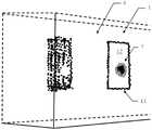
图1示出了扫描带有窗户的建筑物的激光扫描器的实施方式;Figure 1 shows an embodiment of a laser scanner for scanning a building with windows;
图2示出了根据本发明的实施方式的接收信号的时间特性;Figure 2 shows the time characteristic of a received signal according to an embodiment of the present invention;
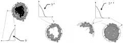
图3示出了根据本发明的实施方式的空间回波脉冲排布;Figure 3 shows a spatial echo pulse arrangement according to an embodiment of the present invention;
图4示出了根据本发明的实施方式的具有圆周形状边缘区域的圆形累积图案;Figure 4 illustrates a circular accumulation pattern with a circumferentially shaped edge region according to an embodiment of the present invention;
图5示出了根据本发明的实施方式的沿径向向外方向的越过圆形累积图案的圆周形状边缘区域的强度衰减。5 illustrates intensity decay in a radially outward direction across a circumferentially shaped edge region of a circular accumulation pattern in accordance with an embodiment of the present invention.
具体实施方式Detailed ways
图1示出了具有带窗户的建筑物的示例性环境2。建筑物的窗户表示透明和/或镜面反射平面候选对象1。建筑物的一侧由作为UAV的一部分的移动激光扫描器3进行扫描。激光扫描器3在发射方向13上发射形成测距光束的测距光脉冲。测距光束的示意图示出为与透明和/或镜面反射平面候选对象相交并进入其后面的部分,测距光束在那里撞击建筑物的墙壁。测距光脉冲至少从图1中由两个黑点指示的两个位置至少部分反向散射,一个位置在透明和/或镜面反射平面候选对象上,另一个在其后面的墙壁上。测距光脉冲的反向散射部分形成随时间记录的接收信号。Figure 1 shows an
图2示出了接收信号4、4'、4”的示例性时间特性。所示的时间特性可以来自于对图1中所示并在发射方向13上发射的发射测距光脉冲的反向散射部分进行检测。实际产生的时间特性在很大程度上取决于测距光脉冲撞击在窗户上的入射角。时间特性表现出一个或更多个回波脉冲5、5'、5”。回波脉冲可以是峰形的。回波脉冲的强度可以高于或低于检测发射的测距光脉冲的反向散射部分的检测器的饱和阈值。如果接收信号的时间特性具有不止一个回波脉冲,则回波脉冲的强度可以相似或不同。两个回波脉冲之间的回波脉冲可以具有与这两个回波脉冲相等、相似或不同(更高或更低)的强度,其中,这两个回波脉冲可以具有相等、相似或不同的强度。FIG. 2 shows an exemplary time characteristic of the received signals 4 , 4 ′, 4 ″. The time characteristic shown may result from the inversion of the transmit ranging light pulse shown in FIG. 1 and transmitted in transmit
图3示出了根据本发明的实施方式的空间回波脉冲排布6。空间回波脉冲排布包括两个累积图案。第一圆形累积图案7和另外的累积图案11,该另外的累积图案11为矩形形状,形成了透明和/或镜面反射平面候选对象1的边界。基于空间回波脉冲排布6及其累积图案7和11,可以根据本发明的实施方式确定透明和/或镜面反射表面12。Figure 3 shows a spatial
图3中的点的色度示意性地指示所关联的识别出的回波脉冲的强度,其中,与较深的色度相比,较浅的色度与较低的强度相关。The chromaticity of the points in Figure 3 schematically indicates the intensities of the associated identified echo pulses, where lighter chromaticities are associated with lower intensities than darker chromatics.
图4示出了根据本发明的实施方式的具有圆周形状边缘区域8、8'、8”、8”'的圆形累积图案7、7'、7”、7”'。圆形累积图案是具有如下形状的图案:该形状可以近似为圆形、圆形的一部分、环形、环形的一部分等。圆形累积图案具有潜在的中点,从该中点可以定义越过边缘区域8、8'、8”、8”'的径向向外方向10、10'、10”、10”'。Figure 4 shows a
图5示出了具有圆周形状边缘区域的圆形累积图案。圆形累积图案的识别出的回波脉冲的空间关联强度可以包括沿径向向外方向的强度演变,该强度演变形成越过圆形累积图案的圆周形状边缘区域的强度衰减9、9'、9”。Figure 5 shows a circular accumulation pattern with a circumferentially shaped edge region. The spatially correlated intensities of the identified echo pulses of the circular accumulation pattern may include an intensity evolution in a radially outward direction that results in an intensity decay 9, 9', 9 across the circumferentially shaped edge regions of the circular accumulation pattern ".
不言而喻,所示的这些附图仅仅是可能的示例性实施方式的示意图。It goes without saying that the figures shown are only schematic representations of possible exemplary embodiments.
Claims (15)
Applications Claiming Priority (2)
| Application Number | Priority Date | Filing Date | Title |
|---|---|---|---|
| EP21165064.3AEP4063897A1 (en) | 2021-03-25 | 2021-03-25 | Computer implemented method for identifying transparent and/or mirroring plane candidates and uav using the same |
| EP21165064.3 | 2021-03-25 |
Publications (1)
| Publication Number | Publication Date |
|---|---|
| CN115201780Atrue CN115201780A (en) | 2022-10-18 |
Family
ID=75252323
Family Applications (1)
| Application Number | Title | Priority Date | Filing Date |
|---|---|---|---|
| CN202210268794.4APendingCN115201780A (en) | 2021-03-25 | 2022-03-18 | Computer-implemented method of identifying transparent and/or mirror plane candidates and UAV using same |
Country Status (3)
| Country | Link |
|---|---|
| US (1) | US12379504B2 (en) |
| EP (1) | EP4063897A1 (en) |
| CN (1) | CN115201780A (en) |
Families Citing this family (2)
| Publication number | Priority date | Publication date | Assignee | Title |
|---|---|---|---|---|
| CN115902915A (en)* | 2022-11-16 | 2023-04-04 | 北京洛必德科技有限公司 | Laser radar-based specular reflection object recognition method, device, and electronic equipment |
| CN116400371B (en)* | 2023-06-06 | 2023-09-26 | 山东大学 | Indoor reflective and transparent object position recognition method and system based on three-dimensional point cloud |
Citations (6)
| Publication number | Priority date | Publication date | Assignee | Title |
|---|---|---|---|---|
| CN1217484A (en)* | 1997-11-17 | 1999-05-26 | 三星电子株式会社 | Printing machine and calculating method of scanning synchronous data |
| US20110073784A1 (en)* | 2009-09-30 | 2011-03-31 | Massachusetts Institute Of Technology | Apparatus and method for generating high-intensity optical pulses with an enhancement cavity |
| CN110060332A (en)* | 2019-04-09 | 2019-07-26 | 上海科技大学 | High-precision three-dimensional based on airborne acquisition equipment builds figure and modeling |
| CN111024053A (en)* | 2019-11-22 | 2020-04-17 | 武汉大学 | Method for acquiring and resolving laser scanning data reflected by convex spherical mirror |
| CN111736164A (en)* | 2020-07-30 | 2020-10-02 | 金华市蓝海光电技术有限公司 | Laser scanning range finder |
| CN111982124A (en)* | 2020-08-27 | 2020-11-24 | 华中科技大学 | Deep learning-based three-dimensional laser radar navigation method and device in glass scene |
Family Cites Families (7)
| Publication number | Priority date | Publication date | Assignee | Title |
|---|---|---|---|---|
| US7944548B2 (en) | 2006-03-07 | 2011-05-17 | Leica Geosystems Ag | Increasing measurement rate in time of flight measurement apparatuses |
| EP1890168A1 (en) | 2006-08-18 | 2008-02-20 | Leica Geosystems AG | Laserscanner |
| EP2620745A1 (en) | 2012-01-30 | 2013-07-31 | Hexagon Technology Center GmbH | Measuring system with a measuring device and a scan module |
| WO2014039623A1 (en) | 2012-09-06 | 2014-03-13 | Faro Technologies, Inc. | Laser scanner with additional sensing device |
| EP3438699A1 (en) | 2017-07-31 | 2019-02-06 | Hexagon Technology Center GmbH | Range finder using spad arrangement for acquiring multiple targets |
| US10946960B2 (en)* | 2017-11-21 | 2021-03-16 | Vantage Robotics, Llc | Anomalous payload detection for multirotor unmanned aerial systems |
| US10787255B2 (en)* | 2018-11-30 | 2020-09-29 | Sky Canoe Inc. | Aerial vehicle with enhanced pitch control and interchangeable components |
- 2021
- 2021-03-25EPEP21165064.3Apatent/EP4063897A1/enactivePending
- 2022
- 2022-03-18CNCN202210268794.4Apatent/CN115201780A/enactivePending
- 2022-03-25USUS17/704,764patent/US12379504B2/enactiveActive
Patent Citations (6)
| Publication number | Priority date | Publication date | Assignee | Title |
|---|---|---|---|---|
| CN1217484A (en)* | 1997-11-17 | 1999-05-26 | 三星电子株式会社 | Printing machine and calculating method of scanning synchronous data |
| US20110073784A1 (en)* | 2009-09-30 | 2011-03-31 | Massachusetts Institute Of Technology | Apparatus and method for generating high-intensity optical pulses with an enhancement cavity |
| CN110060332A (en)* | 2019-04-09 | 2019-07-26 | 上海科技大学 | High-precision three-dimensional based on airborne acquisition equipment builds figure and modeling |
| CN111024053A (en)* | 2019-11-22 | 2020-04-17 | 武汉大学 | Method for acquiring and resolving laser scanning data reflected by convex spherical mirror |
| CN111736164A (en)* | 2020-07-30 | 2020-10-02 | 金华市蓝海光电技术有限公司 | Laser scanning range finder |
| CN111982124A (en)* | 2020-08-27 | 2020-11-24 | 华中科技大学 | Deep learning-based three-dimensional laser radar navigation method and device in glass scene |
Non-Patent Citations (1)
| Title |
|---|
| XITING ZHAO 等: "Mapping with Reflection - Detection and Utilization of Reflection in 3D Lidar Scans", 《IEEE INTERNATIONAL CONFERENCE ON SAFETY, SECURITY, AND RESCUE ROBOTICS(SSRR) 2020》, 11 December 2020 (2020-12-11), pages 27 - 33* |
Also Published As
| Publication number | Publication date |
|---|---|
| EP4063897A1 (en) | 2022-09-28 |
| US12379504B2 (en) | 2025-08-05 |
| US20220334264A1 (en) | 2022-10-20 |
Similar Documents
| Publication | Publication Date | Title |
|---|---|---|
| US11733043B2 (en) | Automatic locating of target marks | |
| CN109870705B (en) | Boundary target identification method and device based on laser radar | |
| US7616817B2 (en) | Three dimensional shape correlator | |
| US6473027B1 (en) | False reflected target elimination and automatic reflector mapping in secondary surveillance radar | |
| US8724094B2 (en) | Apparatus and method of recognizing presence of objects | |
| CN111521161A (en) | Surveying apparatus comprising an event camera | |
| US20210018611A1 (en) | Object detection system and method | |
| US20160153773A1 (en) | Registering of a scene disintegrating into clusters with position tracking | |
| EP2827170A2 (en) | Method and system for determining position and orientation of a measuring instrument | |
| CN115201780A (en) | Computer-implemented method of identifying transparent and/or mirror plane candidates and UAV using same | |
| CN113099120B (en) | Depth information acquisition method and device, readable storage medium and depth camera | |
| US11391821B2 (en) | Near-field pulse detection | |
| JP2000266539A (en) | Inter-vehicle distance measurement device | |
| CN110471086A (en) | A kind of radar survey barrier system and method | |
| WO2022011826A1 (en) | Tof camera and ground obstacle detection method therefor, and ground navigation device | |
| CN117826179A (en) | System and method for classifying and removing object artifacts in light detection and ranging point clouds to enhance detection | |
| CN116472473A (en) | Active sensor system and object detection | |
| US11933884B2 (en) | Radar image processing device, radar image processing method, and storage medium | |
| Peter et al. | Line segmentation of 2d laser scanner point clouds for indoor slam based on a range of residuals | |
| US20240288555A1 (en) | Lidar data processing method | |
| Hebel et al. | Change detection in urban areas by direct comparison of multi-view and multi-temporal ALS data | |
| JP3690260B2 (en) | Vehicle distance measurement method | |
| US20250044455A1 (en) | Information processing device, control method, program, and storage medium | |
| US11815626B2 (en) | Method for detecting intensity peaks of a specularly reflected light beam | |
| US12146764B2 (en) | Ranging method and range finder |
Legal Events
| Date | Code | Title | Description |
|---|---|---|---|
| PB01 | Publication | ||
| PB01 | Publication | ||
| SE01 | Entry into force of request for substantive examination | ||
| SE01 | Entry into force of request for substantive examination |