CN115201732A - Magnetic Resonance Imaging System - Google Patents
Magnetic Resonance Imaging SystemDownload PDFInfo
- Publication number
- CN115201732A CN115201732ACN202210342330.3ACN202210342330ACN115201732ACN 115201732 ACN115201732 ACN 115201732ACN 202210342330 ACN202210342330 ACN 202210342330ACN 115201732 ACN115201732 ACN 115201732A
- Authority
- CN
- China
- Prior art keywords
- magnetic field
- coil
- main
- resonance imaging
- imaging system
- Prior art date
- Legal status (The legal status is an assumption and is not a legal conclusion. Google has not performed a legal analysis and makes no representation as to the accuracy of the status listed.)
- Pending
Links
Images


Classifications
- G—PHYSICS
- G01—MEASURING; TESTING
- G01R—MEASURING ELECTRIC VARIABLES; MEASURING MAGNETIC VARIABLES
- G01R33/00—Arrangements or instruments for measuring magnetic variables
- G01R33/20—Arrangements or instruments for measuring magnetic variables involving magnetic resonance
- G01R33/28—Details of apparatus provided for in groups G01R33/44 - G01R33/64
- G01R33/32—Excitation or detection systems, e.g. using radio frequency signals
- G01R33/36—Electrical details, e.g. matching or coupling of the coil to the receiver
- G01R33/3685—Means for reducing sheath currents, e.g. RF traps, baluns
- G—PHYSICS
- G01—MEASURING; TESTING
- G01R—MEASURING ELECTRIC VARIABLES; MEASURING MAGNETIC VARIABLES
- G01R33/00—Arrangements or instruments for measuring magnetic variables
- G01R33/20—Arrangements or instruments for measuring magnetic variables involving magnetic resonance
- G01R33/28—Details of apparatus provided for in groups G01R33/44 - G01R33/64
- G01R33/38—Systems for generation, homogenisation or stabilisation of the main or gradient magnetic field
- G01R33/3806—Open magnet assemblies for improved access to the sample, e.g. C-type or U-type magnets
- G—PHYSICS
- G01—MEASURING; TESTING
- G01R—MEASURING ELECTRIC VARIABLES; MEASURING MAGNETIC VARIABLES
- G01R33/00—Arrangements or instruments for measuring magnetic variables
- G01R33/20—Arrangements or instruments for measuring magnetic variables involving magnetic resonance
- G01R33/44—Arrangements or instruments for measuring magnetic variables involving magnetic resonance using nuclear magnetic resonance [NMR]
- G01R33/48—NMR imaging systems
- G—PHYSICS
- G01—MEASURING; TESTING
- G01R—MEASURING ELECTRIC VARIABLES; MEASURING MAGNETIC VARIABLES
- G01R33/00—Arrangements or instruments for measuring magnetic variables
- G01R33/20—Arrangements or instruments for measuring magnetic variables involving magnetic resonance
- G01R33/24—Arrangements or instruments for measuring magnetic variables involving magnetic resonance for measuring direction or magnitude of magnetic fields or magnetic flux
- G01R33/246—Spatial mapping of the RF magnetic field B1
- G—PHYSICS
- G01—MEASURING; TESTING
- G01R—MEASURING ELECTRIC VARIABLES; MEASURING MAGNETIC VARIABLES
- G01R33/00—Arrangements or instruments for measuring magnetic variables
- G01R33/20—Arrangements or instruments for measuring magnetic variables involving magnetic resonance
- G01R33/28—Details of apparatus provided for in groups G01R33/44 - G01R33/64
- G01R33/38—Systems for generation, homogenisation or stabilisation of the main or gradient magnetic field
- G01R33/3802—Manufacture or installation of magnet assemblies; Additional hardware for transportation or installation of the magnet assembly or for providing mechanical support to components of the magnet assembly
- G—PHYSICS
- G01—MEASURING; TESTING
- G01R—MEASURING ELECTRIC VARIABLES; MEASURING MAGNETIC VARIABLES
- G01R33/00—Arrangements or instruments for measuring magnetic variables
- G01R33/20—Arrangements or instruments for measuring magnetic variables involving magnetic resonance
- G01R33/28—Details of apparatus provided for in groups G01R33/44 - G01R33/64
- G01R33/38—Systems for generation, homogenisation or stabilisation of the main or gradient magnetic field
- G01R33/385—Systems for generation, homogenisation or stabilisation of the main or gradient magnetic field using gradient magnetic field coils
- G01R33/3856—Means for cooling the gradient coils or thermal shielding of the gradient coils
- G—PHYSICS
- G01—MEASURING; TESTING
- G01R—MEASURING ELECTRIC VARIABLES; MEASURING MAGNETIC VARIABLES
- G01R33/00—Arrangements or instruments for measuring magnetic variables
- G01R33/20—Arrangements or instruments for measuring magnetic variables involving magnetic resonance
- G01R33/28—Details of apparatus provided for in groups G01R33/44 - G01R33/64
- G01R33/42—Screening
- G—PHYSICS
- G01—MEASURING; TESTING
- G01R—MEASURING ELECTRIC VARIABLES; MEASURING MAGNETIC VARIABLES
- G01R33/00—Arrangements or instruments for measuring magnetic variables
- G01R33/20—Arrangements or instruments for measuring magnetic variables involving magnetic resonance
- G01R33/28—Details of apparatus provided for in groups G01R33/44 - G01R33/64
- G01R33/38—Systems for generation, homogenisation or stabilisation of the main or gradient magnetic field
- G01R33/381—Systems for generation, homogenisation or stabilisation of the main or gradient magnetic field using electromagnets
- G01R33/3815—Systems for generation, homogenisation or stabilisation of the main or gradient magnetic field using electromagnets with superconducting coils, e.g. power supply therefor
- G—PHYSICS
- G01—MEASURING; TESTING
- G01R—MEASURING ELECTRIC VARIABLES; MEASURING MAGNETIC VARIABLES
- G01R33/00—Arrangements or instruments for measuring magnetic variables
- G01R33/20—Arrangements or instruments for measuring magnetic variables involving magnetic resonance
- G01R33/28—Details of apparatus provided for in groups G01R33/44 - G01R33/64
- G01R33/42—Screening
- G01R33/422—Screening of the radio frequency field
Landscapes
- Physics & Mathematics (AREA)
- Condensed Matter Physics & Semiconductors (AREA)
- General Physics & Mathematics (AREA)
- Health & Medical Sciences (AREA)
- Epidemiology (AREA)
- High Energy & Nuclear Physics (AREA)
- Magnetic Resonance Imaging Apparatus (AREA)
Abstract
Description
Translated fromChinese本申请以第2021-062583号日本专利申请(申请日:2021年4月1日)为基础,并主张该原专利申请的优先权。本申请通过引用该原专利申请而包含其全部内容。This application is based on Japanese Patent Application No. 2021-062583 (filing date: April 1, 2021), and claims the priority of the original patent application. This application incorporates this original patent application in its entirety by reference.
技术领域technical field
本说明书及附图所公开的实施方式涉及磁共振成像系统。Embodiments disclosed in this specification and the drawings relate to magnetic resonance imaging systems.
背景技术Background technique
磁共振成像装置是一种拍摄装置,用拉莫尔频率的高频(RF:Radio Frequency)信号激发被置于静磁场中的被检体的原子核旋转,对伴随着激发由被检体产生的磁共振信号(MR(Magnetic Resonance)信号)进行重构并生成图像。A magnetic resonance imaging apparatus is a photographing apparatus that uses a Larmor frequency (RF: Radio Frequency) signal to excite the rotation of the nuclei of a subject placed in a static magnetic field, and responds to the magnetic resonance generated by the subject accompanying the excitation. The resonance signal (MR (Magnetic Resonance) signal) is reconstructed and an image is generated.
许多磁共振成像(MRI:Magnetic Resonance Imaging)装置具有被称作旋转门的结构,在旋转门形成有圆筒形的空间(该空间被称作机架孔道(bore))。横卧于顶板的被检体(例如患者)在被搬入圆筒形的空间内的状态下被进行拍摄。在旋转门的内部收纳有圆筒状的静磁场磁体、圆筒状的梯度磁场线圈以及圆筒状的RF线圈(即,WB(Whole Body)线圈)。以往,在许多这种磁共振成像装置中,静磁场磁体、梯度磁场线圈、RF线圈呈圆筒形,因此以下把这种磁共振成像装置称作圆筒型磁共振成像装置。Many magnetic resonance imaging (MRI: Magnetic Resonance Imaging) apparatuses have a structure called a revolving door in which a cylindrical space (the space is called a gantry bore) is formed. The subject (for example, a patient) lying on the top plate is imaged while being carried into the cylindrical space. Inside the revolving door, a cylindrical static magnetic field magnet, a cylindrical gradient magnetic field coil, and a cylindrical RF coil (ie, a WB (Whole Body) coil) are accommodated. Conventionally, in many such magnetic resonance imaging apparatuses, the static magnetic field magnet, the gradient magnetic field coil, and the RF coil have a cylindrical shape, and thus such magnetic resonance imaging apparatuses are hereinafter referred to as cylindrical magnetic resonance imaging apparatuses.
在圆筒型磁共振成像装置中,在机架孔道内的密闭空间中进行拍摄,因此存在例如对于密闭恐怖症等一部分的患者难以拍摄的情况。In a cylindrical magnetic resonance imaging apparatus, imaging is performed in a closed space within the gantry tunnel, and therefore, imaging may be difficult for some patients such as occlusive phobia, for example.
与此相对,已提出并研发了这样构成的磁共振成像装置,把静磁场磁体、梯度磁场线圈以及RF线圈的形状设为例如平板状,例如在被两个平板状的静磁场磁体夹住的开放空间中拍摄患者等被检体。以下,把这种磁共振成像装置称作平面开放型磁共振成像装置、或者简称为开放型磁共振成像装置。在开放型的磁共振成像装置中,由于是在敞开的空间中进行拍摄,因此也能够进行闭所恐怖症的患者的拍摄。On the other hand, a magnetic resonance imaging apparatus having such a configuration has been proposed and developed in which the static magnetic field magnet, the gradient magnetic field coil, and the RF coil are formed, for example, in the shape of a flat plate. Subjects such as patients are photographed in an open space. Hereinafter, such a magnetic resonance imaging apparatus will be referred to as an open-plane magnetic resonance imaging apparatus, or simply referred to as an open magnetic resonance imaging apparatus. In an open-type magnetic resonance imaging apparatus, since imaging is performed in an open space, it is also possible to perform imaging of a patient with close phobia.
另一方面,在开放型磁共振成像装置中,平板状的静磁场磁体的磁场不仅产生于朝向患者所在的拍摄空间的一侧,而且也产生于拍摄空间的相反侧、即拍摄空间的外侧。On the other hand, in an open magnetic resonance imaging apparatus, the magnetic field of the flat-plate static magnetic field magnet is generated not only on the side facing the imaging space where the patient is, but also on the opposite side of the imaging space, that is, outside the imaging space.
以往,在该拍摄空间的外侧产生的磁场不能被有效地利用,反而作为有害的磁场,需要用于抑制该磁场的磁场屏蔽等设备。Conventionally, the magnetic field generated outside the imaging space could not be used effectively, and instead, a device such as a magnetic field shield for suppressing the magnetic field was required as a harmful magnetic field.
发明内容SUMMARY OF THE INVENTION
本说明书及附图所公开的实施方式要解决的课题之一是,在使用了开放型的磁共振成像装置的磁共振成像系统中,使能够有效地利用在拍摄空间的外侧产生的磁场。但是,本说明书及附图所公开的实施方式要解决的课题不限于上述课题。也能够把后述的各实施方式所示的各种结构的各效果所对应的课题确定为其他课题。One of the problems to be solved by the embodiments disclosed in this specification and the drawings is to effectively utilize the magnetic field generated outside the imaging space in a magnetic resonance imaging system using an open-type magnetic resonance imaging apparatus. However, the problems to be solved by the embodiments disclosed in this specification and the drawings are not limited to the above-mentioned problems. The subject corresponding to each effect of the various structures shown in each embodiment described later can also be identified as another subject.
用于解决课题的手段means of solving problems
一实施方式的磁共振成像系统具备:一个以上的磁场单元,至少包括生成支配性地决定磁共振频率的主磁场的开放型的主磁体、生成梯度磁场的梯度磁场线圈、和生成高频磁场的RF线圈;以及一个以上的图像生成单元,使用在所述磁场单元生成的所述主磁场、所述梯度磁场以及所述高频磁场,生成被检体的磁共振图像,所述主磁体配置于相互邻接的检查室之间,在所述相互邻接的检查室分别共同使用在所述开放型的主磁体生成的所述主磁场。A magnetic resonance imaging system according to one embodiment includes: one or more magnetic field units including at least an open-type main magnet that generates a main magnetic field that dominates the magnetic resonance frequency, a gradient magnetic field coil that generates a gradient magnetic field, and a high-frequency magnetic field that generates a high-frequency magnetic field. RF coils; and one or more image generating units for generating a magnetic resonance image of a subject using the main magnetic field, the gradient magnetic field, and the high-frequency magnetic field generated by the magnetic field unit, the main magnets being arranged in Between adjacent examination rooms, the main magnetic field generated by the open-type main magnet is used in common in the mutually adjacent examination rooms.
附图说明Description of drawings
图1是表示以往的开放型磁共振成像装置的结构例的图。FIG. 1 is a diagram showing a configuration example of a conventional open-type magnetic resonance imaging apparatus.
图2是表示有关第一实施方式的磁共振成像系统的结构例的图。FIG. 2 is a diagram showing a configuration example of the magnetic resonance imaging system according to the first embodiment.
图3是表示有关第一实施方式的磁共振成像系统的第一变形例的结构例的图。3 is a diagram showing a configuration example of a first modification of the magnetic resonance imaging system according to the first embodiment.
图4是表示有关第一实施方式的磁共振成像系统的第二变形例的结构例的图。4 is a diagram showing a configuration example of a second modification of the magnetic resonance imaging system according to the first embodiment.
图5是表示有关第二实施方式的第一实施例的磁共振成像系统的结构例的图。FIG. 5 is a diagram showing a configuration example of the magnetic resonance imaging system according to the first example of the second embodiment.
图6是表示有关第二实施方式的第二实施例的磁共振成像系统的结构例的图。6 is a diagram showing a configuration example of a magnetic resonance imaging system according to a second example of the second embodiment.
图7是表示有关第二实施方式的第三实施例的磁共振成像系统的结构例的图。7 is a diagram showing a configuration example of a magnetic resonance imaging system according to a third example of the second embodiment.
图8是表示有关第三实施方式的磁共振成像系统的结构例的图。FIG. 8 is a diagram showing a configuration example of a magnetic resonance imaging system according to a third embodiment.
图9是表示在邻接的两个检查室中分别独立控制梯度磁场与高频磁场的结构的图。FIG. 9 is a diagram showing a configuration in which a gradient magnetic field and a high-frequency magnetic field are independently controlled in two adjacent examination rooms.
图10是表示作为在邻接的两个检查室中高频磁场分别独立控制的结构,梯度磁场使用共同的梯度磁场的结构的图。10 is a diagram showing a configuration in which a common gradient magnetic field is used for the gradient magnetic field as a configuration in which the high-frequency magnetic fields are independently controlled in two adjacent examination rooms.
图11是表示设置用于进一步抑制邻接的检查室之间的RF信号的相互干扰的RF屏蔽的结构的图。FIG. 11 is a diagram showing a configuration in which an RF shield is provided for further suppressing mutual interference of RF signals between adjacent examination rooms.
具体实施方式Detailed ways
下面,根据附图对有关本发明的实施方式进行说明。Hereinafter, embodiments of the present invention will be described with reference to the accompanying drawings.
(第一实施方式)(first embodiment)
在对有关第一实施方式的磁共振成像系统1进行说明之前,简单地对以往的开放型磁共振成像装置进行说明。Before describing the magnetic
图1是表示以往的开放型磁共振成像装置的结构例的图。以往的磁共振成像装置例如具有圆形平板状(换言之,薄圆筒形状)的两个主磁体。FIG. 1 is a diagram showing a configuration example of a conventional open-type magnetic resonance imaging apparatus. A conventional magnetic resonance imaging apparatus has, for example, two main magnets in a circular flat shape (in other words, a thin cylindrical shape).
两个主磁体配置为夹持被检体。根据这种主磁体的配置,在两个主磁体之间敞开的拍摄空间形成有磁场。另外,在两个主磁体中,例如形成为与主磁体相同的圆形平板状的梯度磁场线圈与RF线圈,分别设于朝向拍摄空间的位置。The two main magnets are configured to clamp the subject. According to this configuration of the main magnets, a magnetic field is formed in the imaging space opened between the two main magnets. In addition, in the two main magnets, the gradient magnetic field coil and the RF coil, which are formed in the same circular flat shape as the main magnet, for example, are provided at positions facing the imaging space, respectively.
被检体在由一对主磁体、一对梯度磁场线圈以及一对RF线圈夹住的敞开的拍摄空间中被进行拍摄。另外,在图1中由主磁体延伸的大致圆弧状的虚线示意性地示出了通过主磁体生成的静磁场。The subject is imaged in an open imaging space sandwiched by a pair of main magnets, a pair of gradient magnetic field coils, and a pair of RF coils. In addition, in FIG. 1, the substantially arc-shaped broken line extended by the main magnet schematically shows the static magnetic field generated by the main magnet.
如前述那样,在以往的开放型的磁共振成像装置的主磁体中,在主磁体生成的静磁场不仅产生于朝向被检体(例如患者)所在的拍摄空间的一侧,而且也产生于拍摄空间的相反侧、即拍摄空间的外侧。As described above, in the main magnet of the conventional open-type magnetic resonance imaging apparatus, the static magnetic field generated by the main magnet is generated not only on the side facing the imaging space where the subject (for example, the patient) is located, but also in the imaging The opposite side of the space, that is, the outside of the photographing space.
以往,在该拍摄空间的外侧产生的磁场不能被有效地利用,反而成为有害的磁场。因此,如图1示例的那样,设有用于抑制朝向拍摄空间的外侧的不必要的静磁场的磁轭作为磁场屏蔽。Conventionally, the magnetic field generated outside the imaging space could not be used effectively, but instead became a harmful magnetic field. Therefore, as exemplified in FIG. 1 , a yoke for suppressing an unnecessary static magnetic field toward the outside of the imaging space is provided as a magnetic field shield.
与此相对,以下说明的各实施方式的磁共振成像系统不仅通过主磁体生成的两个方向的静磁场、即朝向拍摄空间的一侧,而且在拍摄空间的相反侧、即拍摄空间的外侧产生的静磁场也能够有效地利用。On the other hand, the magnetic resonance imaging system of each embodiment described below is generated not only by the static magnetic fields in two directions, that is, on the side toward the imaging space, but also on the opposite side of the imaging space, that is, outside the imaging space, by the main magnet. The static magnetic field can also be effectively used.
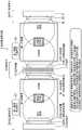
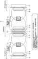
图2是表示有关第一实施方式的磁共振成像系统1的结构例的图。磁共振成像系统1构成为至少具有:一个以上的磁场单元10,配设于相互邻接的多个检查室之间;图像生成单元,与相互邻接的多个检查室分别对应地设置。FIG. 2 is a diagram showing a configuration example of the magnetic
图2既可以理解为从上方观察各检查室与磁场单元10的图,也可以理解为从侧方观察各检查室与磁场单元10的图。以下,虽然出现与图3~图8类似的图,但这些图既可以理解为从上方观察各检查室与磁场单元10的图,也可以理解为从侧方观察各检查室与磁场单元10的图(但图4除外)。FIG. 2 can be understood as a diagram in which each inspection room and the magnetic field unit 10 are viewed from above, or as a diagram in which each inspection room and the magnetic field unit 10 are viewed from the side. 3 to 8 , these figures can be understood as a view of each inspection room and the magnetic field unit 10 viewed from above, or a view of each inspection room and the magnetic field unit 10 viewed from the side. Figures (except Figure 4).
在图2所示的例子中,一个磁场单元10配设于邻接的第一检查室与第二检查室之间的空间中。磁场单元10也可以埋设于第一检查室与第二检查室之间的壁内。或者,也可以在第一检查室与第二检查室之间的壁内设置规定的尺寸的设置用空间,在该设置用空间中配置磁场单元10。In the example shown in FIG. 2, one magnetic field unit 10 is arrange|positioned in the space between the adjacent 1st examination room and the 2nd examination room. The magnetic field unit 10 may be embedded in the wall between the first inspection room and the second inspection room. Alternatively, an installation space of a predetermined size may be provided in the wall between the first inspection room and the second inspection room, and the magnetic field unit 10 may be arranged in the installation space.
在磁场单元10的中央部配置有主磁体11,在主磁体11的第一检查室侧分别配置有第一梯度磁场线圈13与第一RF线圈12。另一方面,在主磁体11的第二检查室侧分别配置有第二梯度磁场线圈15与第二RF线圈14。The
主磁体11、第一梯度磁场线圈13、第二梯度磁场线圈15、第一RF线圈12、以及第二RF线圈14各自的形状例如呈具有规定的厚度的圆筒形状。The shape of each of the
主磁体11生成支配性地决定磁共振频率的主磁场。这里,所谓“支配性地决定磁共振频率的主磁场”,是指以在梯度磁场线圈生成的磁场和在RF线圈生成的磁场不重叠的状态决定磁共振频率的磁场。主磁场并非必须是时间上一定的磁场强度,而是仅在主磁体11生成的磁场。The
另外,本实施方式的主磁体11是开放型的主磁体。所谓开放型的主磁体是指能够形成敞开的拍摄空间的主磁体11,另外,所谓敞开的拍摄空间例如是指在包围被检体的上下、左右、前后这六个方向中的至少三个方向上,不存在与被检体接近的障碍物(例如静磁场磁体或梯度磁场线圈等障碍物)的空间。In addition, the
主磁体11例如在其内部具有超导线圈111,通过在该超导线圈111流过电流而生成主磁场。主磁体11既可以是如图2所示具有超导线圈111的结构,也能够取代超导线圈111,而设为具有常导线圈的结构。The
在将主磁体11设为具有超导线圈111的结构的情况下,在励磁模式中将由主磁体用电源供给的电流施加给超导线圈111使产生静磁场,之后,在移至永久电流模式时,主磁体用电源被切断,使产生始终一定的强度的磁场即静磁场。When the
另一方面,也可以不移至永久电流模式,而考虑诸如在动作中也由主磁体用电源对超导线圈111施加驱动电流,并控制驱动电流使磁场强度变化的动作。另外,即使是由常导线圈构成主磁体11的情况下,也能够进行通过控制施加给常导线圈的驱动电流使磁场强度变化的动作。在这种动作中,能够使通过主磁体11生成的磁场强度变化,在主磁体11生成的磁场严格来说不是“静磁场”。因此,在本说明书中,把在主磁体11生成的磁场不称作“静磁场”,而称作“主磁场”。On the other hand, instead of switching to the permanent current mode, a driving current may be applied to the
通过将主磁体11配设于邻接的两个检查室之间,能够在邻接的两个检查室共用一个主磁体11。例如,通过对构成主磁体11的超导线圈111施加电流,在第一检查室与第二检查室这两方的检查室同时产生主磁场。其结果是,能够在相互邻接的检查室分别共同使用在主磁体11生成的主磁场。By arranging the
另一方面,梯度磁场线圈与RF线圈相对于邻接的两个检查室分别单独设置。例如,在如图2所示第一检查室与第二检查室邻接的情况下,在第一检查室使用的第一梯度磁场,通过在主磁体11的第一检查室侧设置的第一梯度磁场线圈13而生成。另一方面,在第二检查室使用的第二梯度磁场,通过在主磁体11的第二检查室侧设置的第二梯度磁场线圈15而生成。On the other hand, the gradient magnetic field coil and the RF coil are provided independently of each other with respect to the two adjacent examination rooms. For example, when the first inspection chamber and the second inspection chamber are adjacent to each other as shown in FIG. 2 , the first gradient magnetic field used in the first inspection chamber passes the first gradient provided on the first inspection chamber side of the
另外,在第一检查室使用的第一高频磁场,通过在主磁体11的第一检查室侧设置的第一RF线圈12而生成,在第二检查室使用的第二高频磁场,通过在主磁体11的第二检查室侧设置的第二RF线圈14而生成。In addition, the first high-frequency magnetic field used in the first examination room is generated by the
另外,基于提高各检查室内的拍摄区域(例如,图2中在各检查室内的中央部用阴影线示出的区域)中的主磁场分布的均匀性的观点,能够在各检查室的与主磁体11对置的位置配设校正磁体31。例如,在第一检查室和第二检查室的与主磁体11对置的位置配设校正磁体31。In addition, from the viewpoint of improving the uniformity of the distribution of the main magnetic field in the imaging area in each examination room (for example, the area shown by hatching in the central part of each examination room in FIG.
同样,基于提高梯度磁场分布和高频磁场分布的均匀性的观点,也可以在第一检查室的与第一梯度磁场线圈13、第一RF线圈12对置的位置,配设校正梯度磁场线圈33和校正RF线圈32,同样,也可以在第二检查室的与第二梯度磁场线圈15、第二RF线圈14对置的位置,配设校正梯度磁场线圈33和校正RF线圈32。Similarly, from the viewpoint of improving the uniformity of the gradient magnetic field distribution and the high-frequency magnetic field distribution, a correction gradient magnetic field coil may be arranged at a position facing the first gradient
校正磁场单元30由上述的校正磁体31、校正梯度磁场线圈33、以及校正RF线圈32构成。校正磁场单元30既可以埋设于第一检查室以及第二检查室的与磁场单元10对置的壁内,也可以设于与磁场单元10对置的壁的附近(例如壁的外侧或者内侧)。The correction magnetic field unit 30 is constituted by the above-described
另一方面,例如按照每个检查室设有使用主磁场、梯度磁场以及高频磁场生成磁共振图像的图像生成单元。例如,如图2所示,与第一检查室对应地设有第一图像生成单元51,与第二检查室对应地设有第二图像生成单元52。On the other hand, for example, an image generation unit that generates a magnetic resonance image using a main magnetic field, a gradient magnetic field, and a high-frequency magnetic field is provided for each examination room. For example, as shown in FIG. 2 , a first
第一图像生成单元51例如具备顺序控制器、重构处理电路、图像处理电路、显示器装置等而构成。第一图像生成单元51的顺序控制器例如根据所设定的脉冲顺序,控制对第一梯度磁场线圈13和第一RF线圈12施加的梯度磁场电流、发送RF脉冲的大小和施加定时。另外,第一图像生成单元51的重构处理电路对在第一RF线圈12、或者设置于第一检查室的未图示的本地接收线圈接收的磁共振信号进行重构,生成磁共振图像。而且,显示器装置显示所生成的磁共振图像。The first
第二图像生成单元52具有与第一图像生成单元51相同的结构。第二图像生成单元52的顺序控制器例如根据所设定的脉冲顺序,控制对第二梯度磁场线圈15和第二RF线圈14施加的梯度磁场电流、发送RF脉冲的大小和施加定时,并且第二图像生成单元52的重构处理电路对在第二RF线圈14、或者设置于第二检查室的未图示的本地接收线圈接收的磁共振信号进行重构,生成磁共振图像。The second
另外,上述的顺序控制器和重构处理电路能够具备例如通过执行规定的程序来实现上述的各功能的处理器、或实现上述的各功能的FPGA(Field Programmable GateArray,可现场编程门阵列)、ASIC(Application Specific Integrated Circuit,专用集成电路)等硬件而构成。In addition, the above-mentioned sequence controller and reconfiguration processing circuit can include, for example, a processor that implements the above-mentioned functions by executing a predetermined program, an FPGA (Field Programmable Gate Array) that implements the above-mentioned functions, It is constituted by hardware such as ASIC (Application Specific Integrated Circuit, application specific integrated circuit).
根据有关上述的第一实施方式的磁共振成像系统1,能够有效地利用通过主磁体11生成的主磁场,能够通过一个主磁体11生成在邻接的两个检查室使用的主磁场。另外,在主磁体11生成的主磁场不仅在主磁体11的前面侧(例如图2的第一检查室侧),而且在主磁体11的后面侧(例如图2的第二检查室侧)也能有效地利用,因此无需在主磁体11的前面侧或者后面侧中任一方设置磁场屏蔽。According to the magnetic
(第一实施方式的变形例)(Variation of the first embodiment)
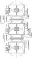
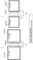
图3是表示有关第一实施方式的磁共振成像系统1的第一变形例的结构例的图。图2所示的第一实施方式是在一个磁场单元10能够进行两个检查室(第一检查室与第二检查室)的拍摄的结构,但磁场单元10的数量也可以是两个以上,在该情况下,能够进行拍摄的检查室的数量达到三个以上。FIG. 3 is a diagram showing a configuration example of a first modification of the magnetic
例如,如图3所示,能够在第一检查室与第二检查室之间配设磁场单元10,在第二检查室与第三检查室之间配设磁场单元10。而且,通过在图3的左方向或者右方向重复图3所示的磁场单元10与检查室的配置,能够使磁共振成像系统1的第一变形例所含的磁场单元10的数量增加。For example, as shown in FIG. 3 , the magnetic field unit 10 can be arranged between the first examination room and the second examination room, and the magnetic field unit 10 can be arranged between the second examination room and the third examination room. Furthermore, by repeating the arrangement of the magnetic field unit 10 and the examination room shown in FIG. 3 in the left or right direction of FIG. 3 , the number of the magnetic field units 10 included in the first modification of the magnetic
图4是表示有关第一实施方式的磁共振成像系统1的第二变形例的结构例的图。在图3所示的第一变形例中,多个磁场单元10与多个检查室呈直线状配置,但多个磁场单元10与多个检查室的配置并不限定于直线状,也可以呈曲线状。例如,也可以如图4示例的那样,将多个磁场单元10与多个检查室配置为圆弧状。FIG. 4 is a diagram showing a configuration example of a second modification of the magnetic
根据第一实施方式的第一变形例或者第二变形例,能够灵活地应对建筑物内的检查室的数量和建筑物内的检查室的排列形状构成磁共振成像系统1。According to the first modification or the second modification of the first embodiment, the magnetic
(第二实施方式)(Second Embodiment)
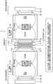
图5是表示有关第二实施方式的第一实施例的磁共振成像系统1的结构例的图。在有关第二实施方式的第一实施例的磁共振成像系统1中,主磁体11包含多个超导线圈或者多个常导线圈,这些线圈相对于主磁体11的中心面对称配置。FIG. 5 is a diagram showing a configuration example of the magnetic
例如,如图5示例的那样,主磁体11包含一个超导线圈111a、两个超导线圈111b而构成。而且,被配置为使一个超导线圈111a的线圈面与主磁体11的中心面一致,两个超导线圈111b分别关于主磁体11的中心面对称配置。For example, as illustrated in FIG. 5 , the
另外,所谓主磁体11的中心面是指与圆筒形状的主磁体11的底平面或者上平面平行的平面,而且是在主磁体11的厚度方向的中央通过的平面。另外,所谓线圈面是指在假设构成超导线圈(或者常导线圈)的环状的导线(也包含导线的数量为多个的情况)的粗细足够小时,包含环状的导线的全周的平面。In addition, the central plane of the
通过由多个超导线圈(或者常导线圈)构成主磁体11,并且将多个超导线圈(或者常导线圈)关于主磁体11的中心面对称配置,能够针对邻接的两个检查室的拍摄区域产生相同的磁场强度(A)的磁场,并能够针对邻接的两个检查室产生关于主磁体11的中心面为对称形状的磁场分布。By configuring the
图6是表示有关第二实施方式的第二实施例的磁共振成像系统1的结构例的图。在有关第二实施方式的第二实施例的磁共振成像系统1中,主磁体11包含多个超导线圈或者多个常导线圈,这些线圈相对于主磁体11的中心面非对称配置。FIG. 6 is a diagram showing a configuration example of a magnetic
例如,如图6示例的那样,主磁体11包含线圈的直径、构成线圈的线材的圈数、材质、剖面尺寸等相互不同的超导线圈111a、超导线圈111b以及超导线圈111c而构成。而且,这些三个超导线圈111a、111b、111c关于主磁体11的中心面非对称配置。For example, as exemplified in FIG. 6 , the
通过关于主磁体11的中心面非对称地配置多个超导线圈,能够针对邻接的两个检查室的拍摄区域产生磁场强度(A)与磁场强度(B)不同的强度的磁场,并能够针对邻接的两个检查室产生关于主磁体11的中心面为非对称形状的磁场分布。By arranging a plurality of superconducting coils asymmetrically with respect to the center plane of the
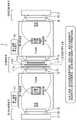
图7是表示有关第二实施方式的第三实施例的磁共振成像系统1的结构例的图。在有关第二实施方式的第三实施例的磁共振成像系统1中,例如由一个超导线圈111构成磁场单元10的主磁体11,而且使校正磁场单元30与校正磁场单元30a各自的校正磁体31的磁场强度在邻接的检查室不同。由此,能够针对邻接的两个检查室的拍摄区域产生磁场强度(A)与磁场强度(C)不同的强度的磁场。FIG. 7 is a diagram showing a configuration example of a magnetic
(第三实施方式)(third embodiment)
图8是表示有关第三实施方式的磁共振成像系统1的结构例的图。在有关第三实施方式的磁共振成像系统1中,仅将磁场单元10中的主磁体11配置于邻接的两个检查室之间的空间中,梯度磁场线圈13、15和RF线圈12、14配设于检查室内。FIG. 8 is a diagram showing a configuration example of the magnetic
例如,仅将主磁体11埋设于邻接的两个检查室之间的壁内,将第一梯度磁场线圈13与第一RF线圈12配设于第一检查室内,将第二梯度磁场线圈15与第二RF线圈14配设于第二检查室内。For example, only the
另外,关于校正磁场单元30,如图8所示,将校正磁体31埋设于各检查室的外部例如各检查室的外部的壁内,另一方面,校正梯度磁场线圈33与校正RF线圈32既可以配设于各检查室的内部,也可以将包含校正磁体31在内的校正磁场单元30整体配设于各检查室的内部。In addition, as for the correction magnetic field unit 30, as shown in FIG. 8, the
根据如上述那样的配置,能够缩窄邻接的两个检查室之间的所要空间、或者检查室的外侧的所要空间。According to the arrangement as described above, the required space between two adjacent examination rooms or the required space outside the examination room can be narrowed.
(其他实施方式)(Other Embodiments)
图9以及图10是表示梯度磁场线圈与RF线圈的电流驱动方法的图。图9示出了在邻接的两个检查室中,分别独立控制梯度磁场与高频磁场的结构。对第一检查室赋予第一梯度磁场的第一梯度磁场线圈13、和对第二检查室赋予第二梯度磁场的第二梯度磁场线圈15,由两个梯度磁场电源被施加彼此不同的梯度磁场电流GIn(1)/GOut(1)、GIn(2)/GOut(2)。9 and 10 are diagrams showing a current driving method of the gradient magnetic field coil and the RF coil. FIG. 9 shows the structure of independently controlling the gradient magnetic field and the high-frequency magnetic field in two adjacent examination rooms. The first gradient
同样,对第一检查室赋予第一高频磁场的第一RF线圈12、和对第二检查室赋予第二高频磁场的第二RF线圈14,由两个发送放大器被施加彼此不同的RF脉冲电流RIn(1)/ROut(1)、RIn(2)/ROut(2)。Similarly, the
与此相对,图10示出了在邻接的两个检查室中分别独立控制高频磁场的结构,而且关于梯度磁场使用共同的梯度磁场的结构。图10(a)示例了对第一检查室用的第一梯度磁场线圈13和第二检查室用的第二梯度磁场线圈15,由一个梯度磁场电源施加共同的梯度磁场电流GIn/GOut的结构。根据这种结构,能够减少梯度磁场电源的数量。On the other hand, FIG. 10 shows a configuration in which high-frequency magnetic fields are independently controlled in two adjacent examination rooms, and a common gradient magnetic field is used for the gradient magnetic field. FIG. 10( a ) illustrates a structure in which a common gradient magnetic field current GIn/GOut is applied to the first gradient
另外,图10(b)示例了不仅梯度磁场电源,而且梯度磁场线圈13也在第一检查室与第二检查室中共同使用的结构。根据这种结构,不仅梯度磁场电源,而且也能够减少梯度磁场线圈的数量。In addition, FIG. 10( b ) illustrates a structure in which not only the gradient magnetic field power supply but also the gradient
另外,图9所示的结构、图10(a)以及图10(b)所示的结构,RF线圈的控制都能够在第一检查室与第二检查室中独立控制。由此,能够使RF信号的接收定时在邻接的检查室之间错开,能够抑制经由空间和云端的相互干扰。In addition, in the configuration shown in FIG. 9 , and the configuration shown in FIGS. 10( a ) and 10 ( b ), the control of the RF coil can be independently controlled in the first inspection room and the second inspection room. Thereby, the reception timing of the RF signal can be shifted between adjacent examination rooms, and the mutual interference via the space and the cloud can be suppressed.
图11是示例设置用于进一步抑制邻接的检查室之间的RF信号的相互干扰的RF屏蔽16的结构的图。RF屏蔽16在第一检查室侧与第二检查室侧分别设于梯度磁场线圈13、15与RF线圈12、14之间。FIG. 11 is a diagram illustrating a structure of an RF shield 16 provided to further suppress mutual interference of RF signals between adjacent examination rooms. The RF shield 16 is provided between the gradient magnetic field coils 13 and 15 and the RF coils 12 and 14 on the first examination room side and the second examination room side, respectively.
如图11(a)所示,在RF线圈12、14配设于第一检查室与第二检查室之间的空间中的情况下,RF屏蔽16在第一检查室与第二检查室之间的空间中设于梯度磁场线圈13、15与RF线圈12、14之间,并且能够设置为包围各检查室。另一方面,如图11(b)所示,在RF线圈12、14配设于第一检查室与第二检查室各自的内部的情况下,RF屏蔽16在第一检查室与第二检查室各自的内部设于梯度磁场线圈13、15与RF线圈12、14之间,并且能够设置为包围各检查室。根据图11(a)以及图11(b)所示的RF屏蔽16,能够抑制通过第一RF线圈12生成的第一高频磁场进入第二检查室,并且抑制通过第二RF线圈14生成的第二高频磁场进入第一检查室。As shown in FIG. 11( a ), when the RF coils 12 and 14 are arranged in the space between the first inspection room and the second inspection room, the RF shield 16 is located between the first inspection room and the second inspection room. The space between the gradient magnetic field coils 13 and 15 and the RF coils 12 and 14 can be provided so as to surround each examination room. On the other hand, as shown in FIG. 11( b ), when the RF coils 12 and 14 are arranged inside the first inspection room and the second inspection room, respectively, the RF shield 16 is placed in the first inspection room and the second inspection room. The interiors of the respective chambers are provided between the gradient magnetic field coils 13 and 15 and the RF coils 12 and 14, and can be provided so as to surround the respective examination chambers. According to the RF shield 16 shown in FIG. 11( a ) and FIG. 11( b ), the first high-frequency magnetic field generated by the
以上对在多个检查室在建筑物的同一楼层中相互邻接的状况下使用的磁共振成像系统1的各实施方式进行了说明,但检查室的配置并不限定于此。即使是多个检查室在建筑物的上下楼层中相互邻接的状况下,也能够应用前述的磁共振成像系统1。在该实施方式的情况下,前述的磁场单元10配设于在建筑物的上下方向上邻接的第一检查室与第二检查室之间的空间中即可,例如埋设于在建筑物的上下方向上邻接的第一检查室与第二检查室之间的地面或者顶棚中即可。As mentioned above, each embodiment of the magnetic
另外,以上将主磁体11的形状设为具有规定的厚度的薄圆筒型(即,平面型)进行了说明,但主磁体11的形状并不限定于平面型,例如也可以是半球型。In the above description, the shape of the
另外,以上说明的磁共振成像系统1构成为如图2、或者图5至图8的各图示例的那样,在邻接的两个检查室中,都是在检查室之间的与主磁体11对置的位置的侧壁内(或者侧壁的附近),设置包含校正磁体31的校正磁场单元30。该校正磁场单元30如前述那样,是为了确保各检查室内的磁场分布的均匀性而设置的。In addition, in the magnetic
另一方面,也能够进行并非必须以磁场分布的均匀性为前提的拍摄。在该情况下,检查室内的磁场分布也可以不均匀,例如也可以是相对于自主磁体11的距离呈线性地变化的磁场分布。在磁场分布不均匀的情况下,将规定的磁场强度或者具有可控性的磁场强度的区域设定为拍摄区域即可。On the other hand, it is also possible to perform imaging that does not necessarily presuppose the uniformity of the magnetic field distribution. In this case, the magnetic field distribution in the examination room may not be uniform, for example, the magnetic field distribution may be changed linearly with respect to the distance of the
在允许检查室内的磁场分布的不均匀性的情况下,在图2或者图5至图8的各图所示的各检查室中,在与主磁体11对置的位置设置的各校正磁场单元30不再需要,能够设为在邻接的两个检查室之间仅设置一个磁场单元10的结构。In each inspection room shown in FIG. 2 or each of FIGS. 5 to 8 , each correction magnetic field unit is provided at a position facing the
根据以上说明的至少一个的实施方式,在使用了开放型的磁共振成像装置的磁共振成像系统中,能够有效地利用在拍摄空间的外侧产生的磁场。According to at least one of the embodiments described above, in the magnetic resonance imaging system using the open-type magnetic resonance imaging apparatus, the magnetic field generated outside the imaging space can be effectively used.
对几个实施方式进行了说明,但这些实施方式是作为例子提示的,并非意图限定发明的范围。这些实施方式能够以其他各种各样的形态实施,在不脱离发明的主旨的范围内能够进行各种各样的省略、替换、变更、实施方式彼此的组合。这些实施方式及其变形被包含在发明的范围或主旨中,同样被包含在权利要求书所记载的发明和其等效的范围中。Several embodiments have been described, but these embodiments are presented as examples and are not intended to limit the scope of the invention. These embodiments can be implemented in various other forms, and various omissions, substitutions, changes, and combinations of the embodiments can be made without departing from the gist of the invention. These embodiments and modifications thereof are included in the scope and spirit of the invention, and are also included in the invention described in the claims and the scope of equivalents thereof.
Claims (16)
Translated fromChineseApplications Claiming Priority (2)
| Application Number | Priority Date | Filing Date | Title |
|---|---|---|---|
| JP2021-062583 | 2021-04-01 | ||
| JP2021062583AJP7666971B2 (en) | 2021-04-01 | 2021-04-01 | Magnetic Resonance Imaging System |
Publications (1)
| Publication Number | Publication Date |
|---|---|
| CN115201732Atrue CN115201732A (en) | 2022-10-18 |
Family
ID=83449038
Family Applications (1)
| Application Number | Title | Priority Date | Filing Date |
|---|---|---|---|
| CN202210342330.3APendingCN115201732A (en) | 2021-04-01 | 2022-03-31 | Magnetic Resonance Imaging System |
Country Status (3)
| Country | Link |
|---|---|
| US (1) | US11946992B2 (en) |
| JP (1) | JP7666971B2 (en) |
| CN (1) | CN115201732A (en) |
Citations (10)
| Publication number | Priority date | Publication date | Assignee | Title |
|---|---|---|---|---|
| JPS61159950A (en)* | 1984-12-31 | 1986-07-19 | 株式会社島津製作所 | Magnet for MRI |
| US5490513A (en)* | 1992-09-28 | 1996-02-13 | Fonar Corporation | Multiple patient breast scanning on a magnetic resonance imaging apparatus |
| US5614880A (en)* | 1990-04-02 | 1997-03-25 | Elscint Ltd. | Superconducting magnet with symmetrical plural air gaps |
| JPH10234704A (en)* | 1997-02-27 | 1998-09-08 | Hitachi Medical Corp | MRI equipment |
| US20020030491A1 (en)* | 2000-07-31 | 2002-03-14 | Katsumi Kose | MRI using multiple RF coils and multiple gradient coils to simultaneously measure multiple samples |
| CN102483447A (en)* | 2009-03-10 | 2012-05-30 | 美时医疗控股有限公司 | MRI system with superconducting main magnet, superconducting gradient field coils and cooled RF coils |
| CN106782998A (en)* | 2016-12-29 | 2017-05-31 | 中国科学院电工研究所 | Open self-shileding magnetic resonance image-forming superconducting magnet |
| KR20180069292A (en)* | 2016-12-15 | 2018-06-25 | 가천대학교 산학협력단 | Magnetic resonance imaging system and method having a wide range of image contrast |
| CN111904420A (en)* | 2019-05-09 | 2020-11-10 | 西门子医疗有限公司 | Magnetic resonance tomography system |
| US20200355771A1 (en)* | 2019-05-09 | 2020-11-12 | Siemens Healthcare Gmbh | Basic field magnet arrangement for a magnetic resonance tomography system |
Family Cites Families (6)
| Publication number | Priority date | Publication date | Assignee | Title |
|---|---|---|---|---|
| US5606970A (en)* | 1992-09-28 | 1997-03-04 | Fonar Corporation | Multiple patient scanning on a magnetic resonance imaging apparatus |
| US5842987A (en)* | 1997-05-20 | 1998-12-01 | Sahadevan; Velayudhan | Simulated patient setup for medical imaging with increased patient throughput |
| US6782571B1 (en)* | 2001-11-30 | 2004-08-31 | Ge Medical Systems | Patient transport system for multiple imaging systems |
| US8073524B2 (en)* | 2007-11-08 | 2011-12-06 | Imris Inc. | Control of magnetic field homogeneity in movable MRI scanning system |
| US8898830B2 (en)* | 2011-04-22 | 2014-12-02 | Medtrak Holding Company, Llc | Patient support and transport system of a multimodality medical suite |
| US9301707B2 (en) | 2012-11-07 | 2016-04-05 | Imris Inc | MR imaging in separate rooms using a magnet having a diagnostic table |
- 2021
- 2021-04-01JPJP2021062583Apatent/JP7666971B2/enactiveActive
- 2022
- 2022-03-30USUS17/657,209patent/US11946992B2/enactiveActive
- 2022-03-31CNCN202210342330.3Apatent/CN115201732A/enactivePending
Patent Citations (10)
| Publication number | Priority date | Publication date | Assignee | Title |
|---|---|---|---|---|
| JPS61159950A (en)* | 1984-12-31 | 1986-07-19 | 株式会社島津製作所 | Magnet for MRI |
| US5614880A (en)* | 1990-04-02 | 1997-03-25 | Elscint Ltd. | Superconducting magnet with symmetrical plural air gaps |
| US5490513A (en)* | 1992-09-28 | 1996-02-13 | Fonar Corporation | Multiple patient breast scanning on a magnetic resonance imaging apparatus |
| JPH10234704A (en)* | 1997-02-27 | 1998-09-08 | Hitachi Medical Corp | MRI equipment |
| US20020030491A1 (en)* | 2000-07-31 | 2002-03-14 | Katsumi Kose | MRI using multiple RF coils and multiple gradient coils to simultaneously measure multiple samples |
| CN102483447A (en)* | 2009-03-10 | 2012-05-30 | 美时医疗控股有限公司 | MRI system with superconducting main magnet, superconducting gradient field coils and cooled RF coils |
| KR20180069292A (en)* | 2016-12-15 | 2018-06-25 | 가천대학교 산학협력단 | Magnetic resonance imaging system and method having a wide range of image contrast |
| CN106782998A (en)* | 2016-12-29 | 2017-05-31 | 中国科学院电工研究所 | Open self-shileding magnetic resonance image-forming superconducting magnet |
| CN111904420A (en)* | 2019-05-09 | 2020-11-10 | 西门子医疗有限公司 | Magnetic resonance tomography system |
| US20200355771A1 (en)* | 2019-05-09 | 2020-11-12 | Siemens Healthcare Gmbh | Basic field magnet arrangement for a magnetic resonance tomography system |
Non-Patent Citations (1)
| Title |
|---|
| 北京医轩国际医学研究院: "新编临床影像技术", 31 December 2019, 江西科学技术出版社, pages: 121* |
Also Published As
| Publication number | Publication date |
|---|---|
| US11946992B2 (en) | 2024-04-02 |
| US20220317212A1 (en) | 2022-10-06 |
| JP2022158004A (en) | 2022-10-14 |
| JP7666971B2 (en) | 2025-04-22 |
Similar Documents
| Publication | Publication Date | Title |
|---|---|---|
| JP6791928B2 (en) | Systems and methods for radiation therapy by magnetic resonance imaging | |
| US20220206094A1 (en) | Unified coil (unic) systems and method for next generation magnetic resonance coils | |
| JP7638358B2 (en) | Unilateral magnetic resonance imaging system with an interventional aperture and method for operating said system - Patents.com | |
| JP4733742B2 (en) | Particle radiotherapy apparatus including magnetic resonance imaging means | |
| JP6422875B2 (en) | Radio frequency (RF) birdcage coil for a magnetic resonance (MR) imaging system having separately controlled ring members and rungs | |
| US6906518B2 (en) | RF coil system for magnetic resonance imaging apparatus | |
| JP3902591B2 (en) | Efficiently shielded MRI gradient coil with discontinuous or continuously variable field of view | |
| JP5600587B2 (en) | Method and apparatus for generating an RF field | |
| US10890637B2 (en) | Magnetic resonance gradient coil for generating a magnetic field gradient and a magnetic field of a higher order | |
| JP6072825B2 (en) | Use of gradient coils to correct higher order BO field inhomogeneities in MR imaging | |
| US11454686B2 (en) | Gradient system for a magnetic resonance imaging system | |
| JP2007203032A (en) | Magnetic resonance imaging apparatus | |
| US5378988A (en) | MRI system having high field strength open access magnet | |
| JP2017531500A (en) | Z-segmented MRI RF coil with gap and RF screen element | |
| KR102038630B1 (en) | Magnetic resonance imaging system | |
| KR20130055538A (en) | Gradient-independent shim coil for a local coil of a magnetic resonance device | |
| US20210181279A1 (en) | Gradient coil unit for a magnetic resonance device | |
| CN112858969A (en) | Gradient system for magnetic resonance imaging system | |
| CN115201732A (en) | Magnetic Resonance Imaging System | |
| JP3707138B2 (en) | Coil arrangement method for magnetic resonance and coil arrangement applied thereto | |
| JP2018528010A (en) | High frequency antenna assembly for magnetic resonance imaging guided therapy | |
| JP2015003030A (en) | Transmitting unit for magnetic resonance tomographic system | |
| JP2004097606A (en) | Rf coil and magnetic resonance imaging device using the same | |
| KR101676192B1 (en) | Multi-channel RF coil array for MRI | |
| JP2002052006A (en) | High frequency coil for nuclear magnetic resonance imaging apparatus and nuclear magnetic resonance imaging apparatus |
Legal Events
| Date | Code | Title | Description |
|---|---|---|---|
| PB01 | Publication | ||
| PB01 | Publication | ||
| SE01 | Entry into force of request for substantive examination | ||
| SE01 | Entry into force of request for substantive examination |