CN115201716A - Sheath protector fault online diagnosis method based on sheath current difference amplitude-frequency characteristic - Google Patents
Sheath protector fault online diagnosis method based on sheath current difference amplitude-frequency characteristicDownload PDFInfo
- Publication number
- CN115201716A CN115201716ACN202210832175.3ACN202210832175ACN115201716ACN 115201716 ACN115201716 ACN 115201716ACN 202210832175 ACN202210832175 ACN 202210832175ACN 115201716 ACN115201716 ACN 115201716A
- Authority
- CN
- China
- Prior art keywords
- sheath
- fault
- current
- protector
- cable
- Prior art date
- Legal status (The legal status is an assumption and is not a legal conclusion. Google has not performed a legal analysis and makes no representation as to the accuracy of the status listed.)
- Granted
Links
- 230000001012protectorEffects0.000titleclaimsabstractdescription157
- 238000003745diagnosisMethods0.000titleclaimsabstractdescription39
- 238000000034methodMethods0.000titleclaimsabstractdescription27
- 238000004364calculation methodMethods0.000claimsabstractdescription21
- 239000011241protective layerSubstances0.000claimsdescription34
- 230000008878couplingEffects0.000claimsdescription20
- 238000010168coupling processMethods0.000claimsdescription20
- 238000005859coupling reactionMethods0.000claimsdescription20
- 230000001939inductive effectEffects0.000claimsdescription10
- 238000001914filtrationMethods0.000claimsdescription3
- 238000004088simulationMethods0.000claimsdescription3
- 238000012546transferMethods0.000claimsdescription3
- 230000002159abnormal effectEffects0.000abstractdescription2
- 238000012423maintenanceMethods0.000abstractdescription2
- 239000002184metalSubstances0.000description65
- 229910052751metalInorganic materials0.000description65
- XLOMVQKBTHCTTD-UHFFFAOYSA-NZinc monoxideChemical compound[Zn]=OXLOMVQKBTHCTTD-UHFFFAOYSA-N0.000description22
- 239000011787zinc oxideSubstances0.000description11
- 238000010586diagramMethods0.000description9
- 238000009413insulationMethods0.000description7
- 239000010410layerSubstances0.000description7
- 238000001514detection methodMethods0.000description4
- 230000008859changeEffects0.000description3
- 230000000694effectsEffects0.000description3
- QVGXLLKOCUKJST-UHFFFAOYSA-Natomic oxygenChemical compound[O]QVGXLLKOCUKJST-UHFFFAOYSA-N0.000description2
- 238000003763carbonizationMethods0.000description2
- 239000004020conductorSubstances0.000description2
- 238000009472formulationMethods0.000description2
- 238000007689inspectionMethods0.000description2
- 239000000203mixtureSubstances0.000description2
- 229910052760oxygenInorganic materials0.000description2
- 239000001301oxygenSubstances0.000description2
- 230000008569processEffects0.000description2
- 101100229815Arabidopsis thaliana GDPDL1 geneProteins0.000description1
- 101100069205Arabidopsis thaliana GDPDL4 geneProteins0.000description1
- 101100069206Arabidopsis thaliana GDPDL5 geneProteins0.000description1
- 101100069207Arabidopsis thaliana GDPDL6 geneProteins0.000description1
- 101100069208Arabidopsis thaliana GDPDL7 geneProteins0.000description1
- 101100204470Saccharomyces cerevisiae (strain ATCC 204508 / S288c) SVL3 geneProteins0.000description1
- 230000015572biosynthetic processEffects0.000description1
- 230000007812deficiencyEffects0.000description1
- 239000011810insulating materialSubstances0.000description1
- 239000011229interlayerSubstances0.000description1
- 239000011159matrix materialSubstances0.000description1
- 238000012986modificationMethods0.000description1
- 230000004048modificationEffects0.000description1
- 238000012544monitoring processMethods0.000description1
- 230000035699permeabilityEffects0.000description1
- HBMJWWWQQXIZIP-UHFFFAOYSA-Nsilicon carbideChemical compound[Si+]#[C-]HBMJWWWQQXIZIP-UHFFFAOYSA-N0.000description1
- 229910010271silicon carbideInorganic materials0.000description1
- 238000012360testing methodMethods0.000description1
Images


Classifications
- G—PHYSICS
- G01—MEASURING; TESTING
- G01R—MEASURING ELECTRIC VARIABLES; MEASURING MAGNETIC VARIABLES
- G01R31/00—Arrangements for testing electric properties; Arrangements for locating electric faults; Arrangements for electrical testing characterised by what is being tested not provided for elsewhere
- G01R31/50—Testing of electric apparatus, lines, cables or components for short-circuits, continuity, leakage current or incorrect line connections
- G01R31/52—Testing for short-circuits, leakage current or ground faults
- G—PHYSICS
- G01—MEASURING; TESTING
- G01R—MEASURING ELECTRIC VARIABLES; MEASURING MAGNETIC VARIABLES
- G01R31/00—Arrangements for testing electric properties; Arrangements for locating electric faults; Arrangements for electrical testing characterised by what is being tested not provided for elsewhere
- G01R31/08—Locating faults in cables, transmission lines, or networks
- G01R31/081—Locating faults in cables, transmission lines, or networks according to type of conductors
- G01R31/085—Locating faults in cables, transmission lines, or networks according to type of conductors in power transmission or distribution lines, e.g. overhead
- G—PHYSICS
- G01—MEASURING; TESTING
- G01R—MEASURING ELECTRIC VARIABLES; MEASURING MAGNETIC VARIABLES
- G01R31/00—Arrangements for testing electric properties; Arrangements for locating electric faults; Arrangements for electrical testing characterised by what is being tested not provided for elsewhere
- G01R31/08—Locating faults in cables, transmission lines, or networks
- G01R31/088—Aspects of digital computing
- Y—GENERAL TAGGING OF NEW TECHNOLOGICAL DEVELOPMENTS; GENERAL TAGGING OF CROSS-SECTIONAL TECHNOLOGIES SPANNING OVER SEVERAL SECTIONS OF THE IPC; TECHNICAL SUBJECTS COVERED BY FORMER USPC CROSS-REFERENCE ART COLLECTIONS [XRACs] AND DIGESTS
- Y04—INFORMATION OR COMMUNICATION TECHNOLOGIES HAVING AN IMPACT ON OTHER TECHNOLOGY AREAS
- Y04S—SYSTEMS INTEGRATING TECHNOLOGIES RELATED TO POWER NETWORK OPERATION, COMMUNICATION OR INFORMATION TECHNOLOGIES FOR IMPROVING THE ELECTRICAL POWER GENERATION, TRANSMISSION, DISTRIBUTION, MANAGEMENT OR USAGE, i.e. SMART GRIDS
- Y04S10/00—Systems supporting electrical power generation, transmission or distribution
- Y04S10/50—Systems or methods supporting the power network operation or management, involving a certain degree of interaction with the load-side end user applications
- Y04S10/52—Outage or fault management, e.g. fault detection or location
Landscapes
- Physics & Mathematics (AREA)
- General Physics & Mathematics (AREA)
- Engineering & Computer Science (AREA)
- Mathematical Physics (AREA)
- Theoretical Computer Science (AREA)
- Testing Of Short-Circuits, Discontinuities, Leakage, Or Incorrect Line Connections (AREA)
Abstract
Translated fromChinese
Description
Translated fromChinese技术领域technical field
本发明涉及高压电缆线路的技术领域,更具体地,涉及一种基于护层电流差幅频特性的护层保护器故障在线诊断方法。The invention relates to the technical field of high-voltage cable lines, and more particularly, to an on-line fault diagnosis method for sheath protectors based on sheath current difference amplitude-frequency characteristics.
背景技术Background technique
目前已有的护层保护器故障监测方法主要依靠人工巡检,并且护层保护器故障和电缆外护套破损等故障引起的工频护层电流变化相近,依靠护层电流幅值、护层电流相对值和护层电流与护层电流差相角等方法难以区分两者。针对护层保护器内部氧化锌阀片的非线性电阻特性,本发明以护层电流差的幅频特性提高护层保护器故障诊断的准确性。At present, the existing sheath protector fault monitoring methods mainly rely on manual inspection, and the power frequency sheath current changes caused by faults such as sheath protector fault and cable outer sheath damage are similar. Methods such as the relative value of the current and the difference between the sheath current and the sheath current are difficult to distinguish between the two. Aiming at the nonlinear resistance characteristics of the zinc oxide valve plate inside the sheath protector, the present invention improves the accuracy of fault diagnosis of the sheath protector by using the amplitude-frequency characteristics of the sheath current difference.
发明内容SUMMARY OF THE INVENTION
本发明针对现有技术中存在的技术问题,给出了工频下电流差以及故障护层保护器泄漏电流的计算方法并建立了护层保护器故障后谐波分量的等效电路模型,设计了以电缆护层电流差的幅频特性为依据的护层保护器故障诊断方法,提高了现阶段护层保护器检修的效率。Aiming at the technical problems existing in the prior art, the present invention provides a calculation method for the current difference under the power frequency and the leakage current of the fault protective layer protector, and establishes an equivalent circuit model of the harmonic components after the protective layer protector fails. The fault diagnosis method of the sheath protector based on the amplitude-frequency characteristic of the cable sheath current difference is presented, which improves the maintenance efficiency of the sheath protector at the present stage.
本发明提供了基于护层电流差幅频特性的护层保护器故障在线诊断方法,包括:The invention provides an on-line fault diagnosis method for a sheath protector based on the differential amplitude-frequency characteristics of sheath current, including:
获取电缆末端与首端的电流差,判断电流差是否等于电缆内部各分段电缆流入的泄漏电流之和,若等于则电缆回路中未发生接地短路故障;反之则线路发生接地短路故障。Obtain the current difference between the end of the cable and the head end, and determine whether the current difference is equal to the sum of the leakage currents flowing into each segmented cable inside the cable. If it is equal, there is no grounding short-circuit fault in the cable loop;
在上述技术方案的基础上,本发明还可以作出如下改进。On the basis of the above technical solutions, the present invention can also make the following improvements.
优选地,所述线路发生接地短路故障之后还包括:判断电流差是否含有谐波,若不含有则电缆回路中未发生其它类型的接地短路故障;若含有则根据预设判据和诊断结果进行护层保护器故障诊断和定位。Preferably, after the ground short-circuit fault occurs in the line, it further includes: judging whether the current difference contains harmonics, if not, no other types of grounding short-circuit faults have occurred in the cable loop; Sheath protector fault diagnosis and location.
优选地,所述根据预设判据和诊断结果进行护层保护器故障诊断和定位包括,通过建立的工频下护层保护器故障后护层电路的电流差和护层保护器故障后谐波分量的等效电路模型,依据护层保护器故障引起护层电流的幅频特性制定故障诊断判据,并判断护层保护器故障所在的回路。Preferably, performing the fault diagnosis and location of the sheath protector according to the preset criteria and the diagnosis results includes: by establishing the current difference of the sheath circuit after the sheath protector fails under the power frequency and the harmonic after the sheath protector failure The equivalent circuit model of the wave component is used to formulate the fault diagnosis criterion according to the amplitude-frequency characteristics of the sheath current caused by the fault of the sheath protector, and determine the circuit where the sheath protector is faulty.
优选地,依据护层保护器故障引起护层电流的幅频特性制定故障诊断判据包括:将故障护层保护器中泄漏电流各次分量等效为谐波源,由故障护层保护器位置注入金属护层回路中,经电缆护层的滤波作用,电缆首末两端的护层电流中的谐波含量因护层保护器故障位置发生改变,并以此制定故障护层保护器中泄漏电流各次谐波含量图作为故障诊断判据。Preferably, formulating the fault diagnosis criterion according to the amplitude-frequency characteristic of the sheath current caused by the fault of the sheath protector includes: equivalently using each component of the leakage current in the sheath protector as a harmonic source, and the position of the sheath protector is determined by the position of the sheath protector. Injected into the metal sheath circuit, through the filtering effect of the cable sheath, the harmonic content of the sheath current at the beginning and end of the cable changes due to the fault position of the sheath protector, and the leakage current in the fault sheath protector is determined accordingly. The harmonic content diagram of each order is used as the fault diagnosis criterion.
优选地,所述获取电缆末端与首端的电流差包括以下步骤:Preferably, the obtaining the current difference between the cable end and the head end includes the following steps:
将6个工频电流互感器安装于交叉互联高压电缆线路两端的接地箱中,同步获取电缆两端护层电流信号;Install 6 power frequency current transformers in the grounding boxes at both ends of the cross-connected high-voltage cable lines, and obtain the current signals of the sheathing at both ends of the cables simultaneously;
将所采集护层电流信号按护层回路分组,分别计算相应分组护层电流差;The collected sheath current signals are grouped according to sheath circuits, and the sheath current differences of the corresponding groups are calculated respectively;
对护层电流差波形做傅里叶变换,得出泄露电流中谐波的含量。The Fourier transform is performed on the current difference waveform of the sheath, and the content of harmonics in the leakage current is obtained.
优选地,所述判断电流差是否等于电缆内部各分段电缆流入的泄漏电流之和包括:Preferably, the judging whether the current difference is equal to the sum of the leakage currents flowing into each segmented cable inside the cable includes:
获取护层保护器等效阻抗;Obtain the equivalent impedance of the sheath protector;
分别建立容性耦合分量和感性耦合分量的等效电路,根据等效电路得到护层故障保护器故障引起的护层电流相量差;The equivalent circuits of the capacitive coupling component and the inductive coupling component are established respectively, and the sheath current phasor difference caused by the fault of the sheath fault protector is obtained according to the equivalent circuit;
根据护层电流相量差计算故障护层保护器含谐波分量的泄漏电流,根据泄漏电流得到基波电流差相角含谐波分量的电流差。Calculate the leakage current of the fault sheath protector with harmonic components according to the phasor difference of the sheath current, and obtain the current difference of the fundamental current with the harmonic components according to the leakage current.
优选地,所述获取护层保护器等效阻抗,包括以下步骤:Preferably, the obtaining the equivalent impedance of the sheath protector includes the following steps:
获取护层保护器的并联等效电阻和并联等效电容;Obtain the parallel equivalent resistance and parallel equivalent capacitance of the sheath protector;
建立等效阻抗计算模型;Establish an equivalent impedance calculation model;
将并联等效电阻和并联等效电容,代入等效阻抗计算模型,得到等效阻抗。Substitute the parallel equivalent resistance and parallel equivalent capacitance into the equivalent impedance calculation model to obtain the equivalent impedance.
优选地,所述等效阻抗计算模型表示为:Preferably, the equivalent impedance calculation model is expressed as:

式中,ZL表示等效阻抗,j表示虚数因子,ω表示工频角速度;Rsvl表示并联等效电阻,Csvl表示并联等效电容。In the formula, ZL represents the equivalent impedance, j represents the imaginary factor, and ω represents the power frequency angular velocity; Rsvl represents the parallel equivalent resistance, and Csvl represents the parallel equivalent capacitance.
优选地,所述根据泄漏电流得到基波电流差相角含谐波分量的电流差包括:Preferably, obtaining the current difference of the fundamental wave current difference phase angle containing harmonic components according to the leakage current includes:
在对护层保护器故障后电缆线路的仿真中,分别建立工频和谐波频率下的护层电路模型,护层保护器故障后谐波分量的等效电路模型中,将故障护层保护器视作谐波源,电缆护层电路等效为串联R-L电路,并且假设电缆首端和末端的地阻抗相等,回路总长度为l的线路中,护层电流差对故障护层保护器泄漏电流的谐波分量的传递函数定义为两者的比值。In the simulation of the cable line after the fault of the sheath protector, the sheath circuit models under the power frequency and the harmonic frequency are established respectively. In the equivalent circuit model of the harmonic component after the sheath protector fault, the fault sheath protection The cable sheath circuit is equivalent to a series R-L circuit, and it is assumed that the ground impedance at the head end and the end of the cable are equal, and in a line with a total loop length of l, the sheath current difference leaks to the fault sheath protector. The transfer function of the harmonic components of the current is defined as the ratio of the two.
本发明的技术效果和优点:Technical effects and advantages of the present invention:
本发明依据护层保护器内部结构中氧化锌阀片的非线性电阻特性,依据电流差谐波含量监测护层保护器故障;建立交叉互联高压电缆等效电路模型,提出以电流差谐波含量为护层保护器故障特征量的检测方法,并给出故障时电流差的计算方法,制定三相九段交叉互联高压电缆系统中护层保护器的故障诊断流程,提高了现阶段护层保护器检修的效率。The invention monitors the fault of the sheath protector according to the non-linear resistance characteristics of the zinc oxide valve sheet in the internal structure of the sheath protector and the harmonic content of the current difference; establishes an equivalent circuit model of a cross-connected high-voltage cable, and proposes to use the harmonic content of the current difference to monitor the fault of the sheath protector. In order to detect the fault characteristic quantity of the sheath protector, and give the calculation method of the current difference when the fault occurs, the fault diagnosis process of the sheath protector in the three-phase nine-segment cross-connected high-voltage cable system is formulated, which improves the current stage of the sheath protector. overhaul efficiency.
本发明的其它特征和优点将在随后的说明书中阐述,并且,部分地从说明书中变得显而易见,或者通过实施本发明而了解。本发明的目的和其他优点可通过在说明书、权利要求书以及附图中所指出的结构来实现和获得。Other features and advantages of the present invention will be set forth in the description which follows, and in part will be apparent from the description, or may be learned by practice of the invention. The objectives and other advantages of the invention may be realized and attained by the structure pointed out in the description, claims and drawings.
附图说明Description of drawings
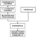
图1为本发明故障诊断方法流程图;Fig. 1 is the flow chart of the fault diagnosis method of the present invention;
图2为本发明护层保护器故障判据制定流程图;Fig. 2 is the flow chart of the fault criterion formulation of the sheath protector of the present invention;
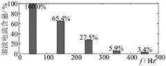
图3为本发明故障护层保护器中泄漏电流各次谐波含量;Fig. 3 is each harmonic content of leakage current in the fault protective layer protector of the present invention;
图4为本发明三相九段式交叉互联高压护层保护器结构图;4 is a structural diagram of a three-phase nine-section cross-connected high-voltage sheath protector according to the present invention;
图5为本发明回路1护层电流示意图;Fig. 5 is the schematic diagram of the sheath current of
图6为本发明回路1护层电路容性耦合分量等效电路图;FIG. 6 is an equivalent circuit diagram of the capacitive coupling component of the sheath circuit of the
图7为本发明回路1护层电路感性耦合分量等效电路图;Fig. 7 is the equivalent circuit diagram of the inductive coupling component of the sheath circuit of the
图8为本发明回路1护层保护器故障后谐波分量的等效电路模型;Fig. 8 is the equivalent circuit model of the harmonic component after the fault of the
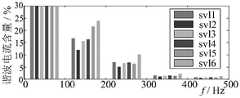
图9为本发明回路1护层保护器故障后谐波分量的电流含量图。FIG. 9 is a current content diagram of harmonic components after the fault of the sheath protector of
具体实施方式Detailed ways
下面将结合本发明实施例中的附图,对本发明实施例中的技术方案进行清楚、完整地描述,显然,所描述的实施例仅仅是本发明一部分实施例,而不是全部的实施例。基于本发明中的实施例,本领域普通技术人员在没有做出创造性劳动前提下所获得的所有其他实施例,都属于本发明保护的范围。The technical solutions in the embodiments of the present invention will be clearly and completely described below with reference to the accompanying drawings in the embodiments of the present invention. Obviously, the described embodiments are only a part of the embodiments of the present invention, but not all of the embodiments. Based on the embodiments of the present invention, all other embodiments obtained by those of ordinary skill in the art without creative efforts shall fall within the protection scope of the present invention.
当护层保护器被击穿,将出现一条由上电极经氧化锌阀片至下电极的碳化通道,此时护层保护器的等效阻抗等物理特性将发生改变,本发明依据氧护层保护器主要组成部分氧化锌阀片的特点。利用护层保护器故障发生时,护层电流的差幅频特性变化实现护层保护器故障在线诊断和定位。When the protective layer protector is broken down, a carbonization channel will appear from the upper electrode to the lower electrode through the zinc oxide valve plate. At this time, the physical characteristics such as the equivalent impedance of the protective layer protector will change. The main components of the protector are the characteristics of the zinc oxide valve plate. When the fault of the sheath protector occurs, the difference amplitude and frequency characteristics of the sheath current are used to realize the on-line diagnosis and location of the sheath protector fault.
为解决现有技术的不足,本发明中提出一种基于护层电流差幅频特性的护层保护器故障在线诊断方法,具体如图1所示,所述方法包含如下步骤:In order to solve the deficiencies of the prior art, the present invention proposes an on-line fault diagnosis method for a sheath protector based on the differential amplitude-frequency characteristics of sheath current, as shown in FIG. 1 , the method includes the following steps:
将6个工频电流互感器安装于交叉互联高压电缆线路的两端的接地箱中,同步获取电缆两端护层电流信号;Install 6 power frequency current transformers in the grounding boxes at both ends of the cross-connected high-voltage cable line, and obtain the current signal of the sheath at both ends of the cable simultaneously;
具体地,在获取电缆末端与首端的电流差后,判断电缆末端与首端电流差的是否等于三小段电缆流入的泄漏电流之和,若等于则电缆回路中未发生接地短路故障,反之则线路发生接地短路故障。Specifically, after obtaining the current difference between the cable end and the head end, determine whether the current difference between the cable end and the head end is equal to the sum of the leakage currents flowing into the three small sections of the cable. A short to ground fault has occurred.
将所采集电流信号按护层回路分组,分别计算相应护层电流差;The collected current signals are grouped according to sheath loops, and the corresponding sheath current differences are calculated respectively;
具体地,计算相应护层电流差步骤包括对护层保护器参数进行测量、建立电缆线路模型、护层保护器故障诊断、故障护层保护器泄漏电流与电流差的计算和故障分类与检测。计算相应护层电流差步骤将在后续进行着重描述,再次不做累述。如图2所示为护层保护器故障判据制定流程图,图中,当判断线路发生接地短路故障之后,还包括判断电流差是否含有谐波,若不含有则电缆回路中未发生其它类型的接地短路故障;若含有则电缆回路中发生接地短路故障。Specifically, the steps of calculating the corresponding sheath current difference include measuring sheath protector parameters, establishing a cable line model, sheath protector fault diagnosis, calculation of the leakage current and current difference of the fault sheath protector, and fault classification and detection. The steps of calculating the corresponding sheath current difference will be described emphatically in the follow-up, and will not be repeated again. Figure 2 shows the flow chart of the fault criterion formulation of the sheath protector. In the figure, after judging that the line has a ground short-circuit fault, it also includes judging whether the current difference contains harmonics. If it does not, no other types have occurred in the cable circuit A short-to-ground fault occurs in the cable loop; if present, a short-to-ground fault occurs in the cable loop.
对护层电流差波形做快速傅里叶变换,得出3、5、7、9次谐波的含量。The fast Fourier transform is performed on the current difference waveform of the sheath, and the content of the 3rd, 5th, 7th and 9th harmonics is obtained.
具体地,根据得出的3、5、7、9次谐波的含量,作为故障诊断的诊断结果。Specifically, according to the content of the obtained 3rd, 5th, 7th, and 9th harmonics, it is used as the diagnosis result of fault diagnosis.
根据预设判据和诊断结果进行护层保护器故障诊断和定位。Carry out fault diagnosis and location of sheath protector according to preset criteria and diagnosis results.
具体地,根据预设判据和诊断结果进行护层保护器故障诊断和定位是通过建立的工频下护层保护器故障后护层电路的电流差和护层保护器故障后谐波分量的等效电路模型,依据护层保护器故障引起护层电流的幅频特性制定故障诊断判据,并判断护层保护器故障所在的回路。Specifically, the fault diagnosis and location of the sheath protector according to the preset criteria and the diagnosis results is based on the established current difference of the sheath circuit after the sheath protector fails at the power frequency and the harmonic components after the sheath protector fails. The equivalent circuit model is used to formulate fault diagnosis criteria according to the amplitude-frequency characteristics of the sheath current caused by the fault of the sheath protector, and determine the circuit where the sheath protector is faulty.
依据护层保护器故障引起护层电流的幅频特性制定故障诊断判据为将故障护层保护器中泄漏电流各次分量等效为谐波源,由故障护层保护器位置注入金属护层回路中,经电缆护层的滤波作用,电缆首末两端的护层电流中的谐波含量因护层保护器故障位置发生改变,并以此制定故障护层保护器中泄漏电流各次谐波含量图作为故障诊断的预设判据。According to the amplitude-frequency characteristics of the sheath current caused by the fault of the sheath protector, the fault diagnosis criterion is formulated as follows: the leakage current in the fault sheath protector is equivalent to a harmonic source, and the metal sheath is injected from the position of the fault sheath protector. In the loop, through the filtering effect of the cable sheath, the harmonic content of the sheath current at the beginning and end of the cable changes due to the fault position of the sheath protector, and based on this, each harmonic of the leakage current in the fault sheath protector is determined. The content map is used as the preset criterion for fault diagnosis.
在本实施例中,故障护层保护器中泄漏电流各次谐波含量根据实验测试,在线路发生接地短路故障的情况下,护层保护器内部的氧化锌阀片在工频100V电压下,泄漏电流中谐波主要为3、5、7、9次谐波,如图3所示为故障护层保护器中泄漏电流各次谐波含量,以基波电流为参考,谐波含量分别为65.4%、27.5%、5.9%和3.4%。本发明制定了三个回路中护层保护器故障诊断的标准,护层保护器故障电流差幅频特性见下表1所示:In this embodiment, the harmonic content of the leakage current in the fault protective layer protector is tested according to the experimental test. In the case of a grounding short-circuit fault on the line, the zinc oxide valve plate inside the protective layer protector is under the power frequency of 100V. The harmonics in the leakage current are mainly the 3rd, 5th, 7th, and 9th harmonics. As shown in Figure 3, the harmonic contents of the leakage current in the fault protective layer protector are shown in Figure 3. Taking the fundamental current as a reference, the harmonic contents are 65.4%, 27.5%, 5.9% and 3.4%. The present invention formulates the standards for fault diagnosis of sheath protectors in three circuits, and the fault current difference amplitude-frequency characteristics of sheath protectors are shown in Table 1 below:
需要说明的是,本发明通过检测高压电缆护层电流,计算电流相位差进行诊断的方法诊断和定位护层保护器故障。应用本发明技术方案,可以在高压电缆护层电流巡检中,有效利用检测电流数据,及时发现并定位护层保护器的故障,以便于后续对故障保护器进行更换,从而有效保护高压电缆护层及绝缘的安全,保障电缆线路的安全运行。It should be noted that the present invention diagnoses and locates the fault of the sheath protector by detecting the sheath current of the high-voltage cable and calculating the current phase difference for diagnosis. By applying the technical solution of the present invention, the detection current data can be effectively used in the current inspection of the high-voltage cable sheath, and the fault of the sheath protector can be found and located in time, so as to facilitate the subsequent replacement of the fault protector, thereby effectively protecting the high-voltage cable protection. Layer and insulation safety, to ensure the safe operation of cable lines.
同时,在上述计算相应护层电流差包括以下部分:At the same time, the corresponding sheath current difference in the above calculation includes the following parts:
01)对护层保护器参数进行测量01) Measure the parameters of the sheath protector
在本实施例中,电缆由外向内依次包括外护层、金属护层、绝缘层和电缆线芯,其中,护层保护器安装于交叉互联电缆线路中两个金属护层分段之间的交叉互联接地箱中,通常35kV大截面电力电缆和66kV、110kV及以上电压等级的电力电缆均为单芯电缆,电缆金属护层一端三相互联并接地,另一端不接地,当雷电波或内部过电压沿电缆线芯流动时,电缆金属护层不接地端会出现较高的冲击过电压,或当系统短路事故电流流经电缆线芯时,其护层不接地端也会出现很高的工频感应过电压。上述过电压可能击穿电缆外护层绝缘,造成电缆金属护层多点接地故障,严重影响电力电缆正常运行甚至大幅减少电缆使用寿命。因此,为限制电力电缆金属护层上的感应电压和故障过电压,并避免在护层中形成环流,电缆护层一端直接接地,另一端则须通过护层保护器接地。如果线路较长,可以将电缆护层分三段或三的倍数段相互绝缘,分段处的护层交叉互联后通过护层保护器接地。护层保护器采用ZnO压敏电阻或ZnO阀片作为保护元件,ZnO阀片无串联间隙,具有优良的电压-电流特性曲线。护层保护器用绝缘材料作为外绝缘,较传统的放电间隙保护、带间隙碳化硅电阻片保护等方式,其伏安特性更显优越。In this embodiment, the cable sequentially includes an outer sheath, a metal sheath, an insulating layer and a cable core from the outside to the inside, wherein the sheath protector is installed between two metal sheath segments in the cross-connected cable line In the cross-connected grounding box, usually 35kV large-section power cables and power cables with voltage levels of 66kV, 110kV and above are single-core cables. One end of the cable metal sheath is three-phase interconnected and grounded, and the other end is not grounded. When the overvoltage flows along the cable core, the ungrounded end of the metal sheath of the cable will have a high impulse overvoltage, or when the system short-circuit accident current flows through the cable core, the ungrounded end of the sheath will also have a high impact. Power frequency induced overvoltage. The above-mentioned overvoltage may break down the insulation of the outer sheath of the cable, causing multi-point grounding faults in the metal sheath of the cable, which seriously affects the normal operation of the power cable and even greatly reduces the service life of the cable. Therefore, in order to limit the induced voltage and fault overvoltage on the metal sheath of the power cable and avoid the formation of circulating current in the sheath, one end of the cable sheath is directly grounded, and the other end must be grounded through the sheath protector. If the line is long, the cable sheath can be insulated from each other in three sections or multiples of three, and the sheaths at the sections are cross-connected and grounded through the sheath protector. The protective layer protector uses ZnO varistor or ZnO valve plate as the protection element. The ZnO valve plate has no series gap and has excellent voltage-current characteristic curve. The sheath protector uses insulating material as the outer insulation, and its volt-ampere characteristics are more superior than the traditional discharge gap protection and silicon carbide resistance chip protection with gaps.
在实际应用中,若护层保护器被击穿,将出现一条由上电极经氧化锌阀片至下电极的碳化通道,此时护层保护器的等效阻抗等物理特性将发生改变,依据氧护层保护器主要组成部分氧化锌阀片的特点,建立护层保护器的等效电路模型,其中,建立护层保护器的等效电路模型,包括以下步骤:获取故障护层保护器的并联等效电阻Rsvl和并联等效电容Csvl;建立等效阻抗计算模型,将并联等效电阻Rsvl和并联等效电容Csvl代入等效阻抗计算模型,得到等效阻抗ZL。在本实施例中,利用交流电桥可测得故障护层保护器的并联等效电阻Rsvl和并联等效电容Csvl,等效电阻Rsvl和等效电容Csvl之间并联连接,计算等效阻抗ZL包括将并联等效电阻Rsvl和并联等效电容Csvl代入下式1的等效阻抗计算模型中求出等效阻抗ZL,In practical applications, if the sheath protector is broken down, a carbonization channel will appear from the upper electrode through the zinc oxide valve plate to the lower electrode. At this time, the physical characteristics such as the equivalent impedance of the sheath protector will change. According to The characteristics of the zinc oxide valve plate, the main component of the oxygen sheath protector, establish the equivalent circuit model of the sheath protector, wherein, establishing the equivalent circuit model of the sheath protector includes the following steps: obtaining the fault sheath protector Parallel equivalent resistance Rsvl and parallel equivalent capacitance Csvl ; establish an equivalent impedance calculation model, and substitute the parallel equivalent resistance Rsvl and parallel equivalent capacitance Csvl into the equivalent impedance calculation model to obtain the equivalent impedance ZL . In this embodiment, the parallel equivalent resistance Rsvl and the parallel equivalent capacitance Csvl of the fault protective layer protector can be measured by using an AC bridge, and the parallel connection between the equivalent resistance Rsvl and the equivalent capacitance Csvl can be calculated, etc. The effective impedance ZL consists of substituting the parallel equivalent resistance Rsvl and the parallel equivalent capacitance Csvl into the equivalent impedance calculation model of the following

式中,j表示虚数因子,ω表示工频角速度;Rsvl表示并联等效电阻,Csvl表示并联等效电容。In the formula, j represents the imaginary factor, ω represents the power frequency angular velocity; Rsvl represents the parallel equivalent resistance, and Csvl represents the parallel equivalent capacitance.
02)建立电缆线路模型02) Establish a cable line model
本发明采用三相九段式交叉互联高压护层保护器,具体如图4所示,电缆护层分三段相互绝缘,在图4中电缆护层的9个金属护套分段将由第一段金属护套S1、第二段金属护套S2、第三段金属护套S3、第四段金属护套S4、第五段金属护套S5、第六金属段护套S6、第七金属段护套S7、第八段金属护套S8和第九段金属护套S9组成。其中,第一段金属护套S1、第五段金属护套S5和第九段金属护套S9组成护层回路1;第四段金属护套S4、第八段金属护套S8和第三段金属护套S3组成护层回路2;第七段金属护套S7、第二段金属护套S2和第六段金属护套S6组成护层回路3。第一护层保护器ZSVL1、第二护层保护器ZSVL2、第三护层保护器ZSVL3、第四护层保护器ZSVL4、第五护层保护器ZSVL5、第六护层保护器ZSVL6分别安装于电缆线路首端的第一电流传感器cs1、第二电流传感器cs2和第三电流传感器cs3上,和安装于电缆线路尾端的第四电流传感器cs4、第五电流传感器cs5、第六电流传感器cs6上。其中,
3)护层保护器故障诊断3) fault diagnosis of sheath protector
本发明以回路1为例进行重点说明,回路2和回路3与回路1类似,在此不在赘述。具体如图5所示为回路1护层电流示意图,第一段金属护套S1、第五段金属护套S5和第九段金属护套S9之间串联连接,Ics1、Ics5分别为电流传感器cs1、cs5处测量得到的护层对地电流;ILS1、ILS5和ILS9分别表示由电缆线芯流入第一段金属护套S1、第五段金属护套S5和第九段金属护套S9的泄漏电流,在正常无故障情况下,由基尔霍夫电流定律在金属护层中电流差等于第一段金属护套S1上流入的泄漏电流:The present invention takes the

在互层保护器发生故障情况下,此时护层保护器的等效阻抗等物理特性将发生改变,依据氧护层保护器主要组成部分氧化锌阀片的特点。利用护层保护器故障发生时,护层电流的差幅频特性变化实现护层保护器故障在线诊断和定位。本发明考虑到故障护层保护器的非线性电阻特性,以异常电流差是否含有谐波区分出护层保护器故障和其他类型的接地短路故障;通过建立的工频下护层保护器故障后护层电路的电流差和护层保护器故障后谐波分量的等效电路模型,依据护层保护器故障引起护层电流的幅频特性制定故障诊断判据,并判断护层保护器故障所在的回路。In the event of failure of the interlayer protector, the physical characteristics such as the equivalent impedance of the sheath protector will change, according to the characteristics of the zinc oxide valve plate, which is the main component of the oxygen sheath protector. When the fault of the sheath protector occurs, the difference amplitude and frequency characteristics of the sheath current are used to realize the on-line diagnosis and location of the sheath protector fault. The invention takes into account the nonlinear resistance characteristics of the fault protective layer protector, and distinguishes the protective layer protector fault from other types of grounding short-circuit faults according to whether the abnormal current difference contains harmonics; The current difference of the sheath circuit and the equivalent circuit model of the harmonic components after the sheath protector fails, the fault diagnosis criterion is formulated according to the amplitude-frequency characteristics of the sheath current caused by the sheath protector fault, and the fault of the sheath protector is determined. circuit.
3)故障护层保护器泄漏电流与电流差的计算3) Calculation of leakage current and current difference of fault sheath protector
为分析故障阻抗与检测护层电流的关系,本发明给出了工频下电流差以及故障护层保护器泄漏电流的计算方法。相较于绝缘阻抗,护层保护器对地阻抗可以忽略,因此假设护层保护器接地故障时,泄漏电流与正常时相等。相较于故障点,同一回路中另一个正常护层保护器阻抗很大,对地视为开路。为便于计算,假设电缆线路末端与首端的地阻抗近似相等,即Re1=Re2=R。In order to analyze the relationship between the fault impedance and the detection sheath current, the present invention provides a calculation method for the current difference under the power frequency and the leakage current of the fault sheath protector. Compared with the insulation resistance, the impedance of the sheath protector to ground can be ignored, so it is assumed that when the sheath protector is grounded, the leakage current is equal to that of normal. Compared with the fault point, another normal sheath protector in the same circuit has a large impedance and is regarded as an open circuit to the ground. For the convenience of calculation, it is assumed that the ground impedances at the end of the cable line and the head end are approximately equal, that is,Re1 =Re2 =R.
判断电流差是否等于电缆内部各分段电缆流入的泄漏电流之和包括计算护层保护器泄漏电流与电流差,其具体为分别建立容性耦合分量和感性耦合分量的等效电路,根据等效电路得到护层故障保护器故障引起的护层电流相量差;根据护层电流相量差计算故障护层保护器含谐波分量的泄漏电流,根据泄漏电流得到基波电流差相角含谐波分量的电流差。在本实施例中,交叉互联高压电缆护层电流为容性耦合电流分量和感性耦合电流分量叠加,因此需分别建立容性耦合分量和感性耦合分量的等效电路模型。Determining whether the current difference is equal to the sum of the leakage currents flowing into each segment of the cable includes calculating the leakage current and current difference of the sheath protector. The circuit obtains the sheath current phasor difference caused by the fault of the sheath fault protector; according to the sheath current phasor difference, the leakage current of the fault sheath protector containing harmonic components is calculated, and the fundamental wave current difference phase angle containing harmonic components is obtained according to the leakage current. The current difference of the wave component. In this embodiment, the sheath current of the cross-connected high-voltage cable is the superposition of the capacitive coupling current component and the inductive coupling current component, so it is necessary to establish equivalent circuit models of the capacitive coupling component and the inductive coupling component respectively.
①容性耦合电流分量计算①Calculation of capacitive coupling current component
图6为回路1护层电路容性耦合分量等效电路图,图中,EA1为第一段金属护套S1处的感应电压,EB2为第五段金属护套S5处的感应电压,EC3为第九段金属护套S9处的感应电压;ZSA1为第一段金属护套S1处的护层阻抗,ZSB2为第五段金属护套S5处的护层阻抗,ZSC3为第九段金属护套S9处的护层阻抗。Ics1m和Ics2m分别为第一电流传感器cs1和第五电流传感器cs1处测得的感性耦合电流。Figure 6 is the equivalent circuit diagram of the capacitive coupling component of the sheath circuit of
电缆金属护套阻抗ZS计算过程见式(3),The calculation process of cable metal sheath impedance ZS is shown in formula (3),

式中l为电缆长度;RS为金属护套单位长度电阻;DS为护套平均直径;f为系统运行的工频频率,ω表示工频角速度。In the formula, l is the cable length; RS is the resistance per unit length of the metal sheath; DS is the average diameter of the sheath; f is the power frequency frequency of the system operation, and ω represents the power frequency angular velocity.
MX,Sn为x相电缆线芯与电缆第Sn段护层间的互感:MX, Sn is the mutual inductance between the x-phase cable core and the sheath of the Sn section of the cable:

式中,dx,Sy为x相电缆线芯与Sn段电缆护层间的平均几何距离,μ0为真空磁导率,ln为各小段电缆的长度。In the formula, dx, Sy is the average geometric distance between the x-phase cable core and the Sn-section cable sheath, μ0 is the vacuum permeability, andln is the length of each small section of the cable.
护层第一段金属护套S1、第五段金属护套S5和第九段金属护套S9上护层感应电压计算公式如下:The calculation formula of the induced voltage on the upper sheath of the first metal sheath S1, the fifth metal sheath S5 and the ninth metal sheath S9 of the sheath is as follows:

式中,ES1、ES5、ES9分别为护套S1、S5和S9段上产生的护层感应电压;MA,S1、MB,S1、MC,S1分别为A、B、C三相电缆对第一段金属护套S1的互感;MA,S5、MB,S5、MC,S5分别为A、B、C三相电缆对第一段金属护套S5的互感;MA,S9、MB,S9、MC,S9分别为A、B、C三相电缆对第一段金属护套S9的互感;IA、IB、IC分别为电缆A、B、C三相的负载电流。In the formula, ES1 , ES5 , and ES9 are the sheath induced voltages generated on the sheath S1, S5 and S9 segments, respectively; MA, S1 , MB, S1 , MC, S1 are A, B, C, respectively Mutual inductance of the three-phase cable to the first section of the metal sheath S1; MA, S5 , MB, S5 , MC, S5 are the mutual inductance of the A, B, C three-phase cables to the first section of the metal sheath S5; MA, S9 , MB, S9 , MC, S9 are the mutual inductances of the A, B, C three-phase cables to the first metal sheath S9; IA , IB , IC are the cables A, B, C, respectively Three-phase load current.
②感性耦合电流分量计算②Calculation of inductive coupling current component
图7为回路1护层电路感性耦合分量等效电路图,图中,ES1为第一段金属护套S1处的感应电压,ES5为第五段金属护套S5处的感应电压,ES9为第九段金属护套S9处的感应电压;ZS1为第一段金属护套S1处的护层阻抗,ZS5为第五段金属护套S5处的护层阻抗,ZS9为第九段金属护套S9处的护层阻抗。Ics1m和Ics2m分别为第一电流传感器cs1和第五电流传感器cs1处测得的感性耦合电流。Figure 7 is the equivalent circuit diagram of the inductive coupling component of the sheath circuit of
③互层电流向量差的计算③Calculation of the current vector difference between layers
具体地,根据等效电路得到护层故障保护器故障引起的护层电流相量差包括:在工频f1=50Hz下,对回路1护层保护器故障S1-S2-S3电路分析;Specifically, obtaining the sheath current phasor difference caused by the fault of the sheath fault protector according to the equivalent circuit includes: at the power frequency f1 =50Hz, the circuit analysis of the fault S1-S2-S3 of the sheath protector of
计算电缆绝缘电容Ci:Calculate the cable insulation capacitance Ci :

其中,ε为绝缘层相对介电常数;ε0为真空中介电常数;DC为线芯导体直径;DS为电缆金属护层的平均几何直径。Among them, ε is the relative dielectric constant of the insulating layer; ε0 is the dielectric constant in vacuum; DC is the diameter of the core conductor; DS is the average geometric diameter of the metal sheath of the cable.
在第一回路中,ILS1为第一段金属护套S1处的容性耦合分量电流,ILS5为第五段金属护套S5处的容性耦合分量电流,ILS9为第九段金属护套S9处的容性耦合分量电流,其中ω1为工频对应的角速度。In the first loop, ILS1 is the capacitive coupling component current at the first metal sheath S1, ILS5 is the capacitive coupling component current at the fifth metal sheath S5, and ILS9 is the ninth metal sheath Capacitive coupling component current at sleeve S9, where ω1 is the angular velocity corresponding to the power frequency.

第一回路中工作电压向量为Uloop1,其中UA、UB、UC分别为A、B、C相的工作电压;负载电流向量为Iloop1,其中IA、IB、IC分别为A、B、C相的负载电流;电缆绝缘层等效电容向量为Ci,其中CS1、CS5、CS9分别为第一段金属护套S1、第五段金属护套S5和第九段金属护套S9的等效电容;Mloop1为回路1中电缆护层与线芯的互感矩阵,其中x相线芯与护层Sn段互阻抗定义为Zx,Sn:The working voltage vector in the first loop is Uloop1 , whereUA , UB , and UC are the working voltages of phasesA ,B , andC , respectively; the load current vector is Iloop1 , where IA ,IB , andIC are respectively The load current of phase A, B and C; the equivalent capacitance vector of the cable insulation layer is Ci , where CS1 , CS5 , and CS9 are the first metal sheath S1 , the fifth metal sheath S5 and the ninth metal sheath respectively The equivalent capacitance of segment metal sheath S9; Mloop1 is the mutual inductance matrix between the cable sheath and the core in
Uloop1=[UA UB UC] (8)Uloop1 = [UA UB UC ] (8)
Iloop1=[IA IB IC]T (9)Iloop1 = [IA IB IC ]T (9)
Ci=[CS1 CS5 CS9] (10)Ci = [CS1 CS5 CS9 ] (10)

回路1中护层保护器svl1故障引起的护层电流相量差Iloop1,svl1为:The sheath current phasor difference Iloop1, svl1 caused by the fault of the sheath protector svl1 in

同理可得护层保护器svl5故障引起的护层电流相量差Iloop1,svl5为:Similarly, the sheath current phasor difference Iloop1, svl5 caused by the fault of the sheath protector svl5 can be obtained as:

④故障护层保护器含谐波分量的泄漏电流的计算④Calculation of leakage current of fault protective layer protector with harmonic components
根据护层电流相量差Iloop1,svl5计算故障护层保护器含谐波分量的泄漏电流包括:According to the sheath current phasor difference Iloop1, svl5, calculating the leakage current of the fault sheath protector with harmonic components includes:
工频下护层保护器svl1、svl5分别故障后通过故障护层保护器的泄漏电流计算公式如下:The formula for calculating the leakage current through the fault protective layer protector after the protective layer protectors svl1 and svl5 respectively fail under the power frequency is as follows:


由于谐波相角的随机性,设各次谐波电流的相角等于基波电流的相角φsvl(1),谐波次数为h以护层保护器svl1故障为例,故障护层保护器含谐波分量的泄漏电流为:Due to the randomness of the harmonic phase angle, the phase angle of each harmonic current is set equal to the phase angle of the fundamental current φsvl(1) , and the harmonic order is h. Taking the fault of the sheath protector svl1 as an example, the fault sheath protection The leakage current of the device with harmonic components is:

在对护层保护器故障后电缆线路的仿真中,将分别建立工频和谐波频率下的护层电路模型。将故障护层保护器视作谐波源,电缆护层电路等效为串联R-L电路,护层保护器故障后谐波分量的等效电路模型如图8所示,图中,RS1、Ls1、RS5、Ls5、RS9、Ls9之间串联,Ics1m和Ics2m分别为第一电流传感器cs1和第五电流传感器cs1处测得的感性耦合电流;在串联R-L电路中,单位长度电感LS(单位为H/m),单位长度电阻RS(单位为Ω/m),并且假设电缆首端和末端的地阻抗相等。回路1总长度为l的线路中,护层电流差对故障护层保护器泄漏电流的谐波分量的传递函数定义为两者的比值G(ω)。In the simulation of the cable line after the fault of the sheath protector, the sheath circuit model under the power frequency and the harmonic frequency will be established respectively. Considering the fault protector as a harmonic source, the cable sheath circuit is equivalent to a series RL circuit, and the equivalent circuit model of the harmonic components after the fault of the sheath protector is shown in Figure 8. In the figure, RS1 , Ls1 , RS5 , Ls5 , RS9 , and Ls9 are connected in series, and Ics1m and Ics2m are the inductive coupling currents measured at the first current sensor cs1 and the fifth current sensor cs1 respectively; in the series RL circuit, the unit Length inductance, LS (in H/m), resistance per unit length, RS (in Ω/m), and assumes equal ground impedance at the beginning and end of the cable. In the line with the total length of

⑤基波电流差相角含谐波分量的电流差的计算;⑤Calculation of the current difference of the fundamental wave current difference phase angle including harmonic components;
根据泄漏电流得到基波电流差相角含谐波分量的电流差包括:According to the leakage current, the current difference including the harmonic component of the fundamental wave current difference phase angle includes:
护层保护器svl1故障时,基波电流差相角φ(1)含谐波分量的电流差计算公式为:When the sheath protector svl1 fails, the fundamental wave current difference phase angle φ(1) The calculation formula of the current difference with harmonic components is:

5)故障分类与检测5) Fault classification and detection
以收集到的故障护层保护器为例等效电阻Rsvl=216Ω,图9为护层保护器svl1~svl6分别故障时对应护层回路中电流差的幅频特性。在本实施例中,电缆参数如下表2所示,Taking the collected fault protective layer protector as an example, the equivalent resistance Rsvl = 216Ω, and Fig. 9 shows the amplitude-frequency characteristics of the current difference in the corresponding protective layer circuit when the protective layer protectors svl1 to svl6 fail respectively. In this embodiment, the cable parameters are shown in Table 2 below,
在已知线路参数表2和护层保护器故障阻抗的情况下,可通过上述方法计算故障所在护层回路的电流差。并判断电流差是否等于电缆内部各分段电缆流入的泄漏电流之和,若等于则电缆回路中未发生接地短路故障;反之则线路发生接地短路故障,当线路发生接地短路故障时,还要判断电流差是否含有谐波,若不含有则电缆回路中未发生其它类型的接地短路故障;若含有则电缆回路中发生接地短路故障,并将谐波与图9中的泄漏电流中谐波进行比对,判断护层保护器故障所在的回路。When the line parameter table 2 and the fault impedance of the sheath protector are known, the current difference of the sheath circuit where the fault is located can be calculated by the above method. And judge whether the current difference is equal to the sum of the leakage currents flowing into each segment of the cable. If it is equal, there is no grounding short-circuit fault in the cable loop; otherwise, the line has a grounding short-circuit fault. Whether the current difference contains harmonics, if not, no other types of grounding short-circuit faults have occurred in the cable loop; if so, grounding short-circuit faults have occurred in the cable loop, and the harmonics are compared with the harmonics in the leakage current in Figure 9 Yes, determine the circuit where the sheath protector is faulty.
在本实施例中,在制定判据时需考虑现场电缆参数、电缆线芯电流、三小段电缆长度、地阻抗以及线芯电压等影响因素的影响。In this embodiment, the influence of factors such as on-site cable parameters, cable core current, length of three small cables, ground impedance, and core voltage need to be considered when formulating the criterion.
综上所示,本发明建立了三相九段式交叉互联高压电缆等效模型,提出护层保护器故障时,工频下护层保护器中泄漏电流以及电流差的计算方法。将故障护层保护器等效产生的各次谐波电流等效为谐波源注入电缆护层电路中,并建立对应的谐波电路模型。本发明以电流差谐波含量作为特征量,辨别线路中故障是否为护层保护器故障并确定护层保护器故障所在回路。In summary, the present invention establishes an equivalent model of a three-phase nine-section cross-connected high-voltage cable, and proposes a calculation method for the leakage current and current difference in the sheath protector under power frequency when the sheath protector fails. Each harmonic current equivalently generated by the fault sheath protector is equivalently injected into the cable sheath circuit as a harmonic source, and the corresponding harmonic circuit model is established. The present invention uses the harmonic content of the current difference as the characteristic quantity to identify whether the fault in the line is the fault of the sheath protector and to determine the circuit where the sheath protector is faulty.
最后应说明的是:以上所述仅为本发明的优选实施例而已,并不用于限制本发明,尽管参照前述实施例对本发明进行了详细的说明,对于本领域的技术人员来说,其依然可以对前述各实施例所记载的技术方案进行修改,或者对其中部分技术特征进行等同替换,凡在本发明的精神和原则之内,所作的任何修改、等同替换、改进等,均应包含在本发明的保护范围之内。Finally, it should be noted that the above descriptions are only preferred embodiments of the present invention, and are not intended to limit the present invention. Although the present invention has been described in detail with reference to the foregoing embodiments, for those skilled in the art, the The technical solutions described in the foregoing embodiments can be modified, or some technical features thereof can be equivalently replaced, and any modifications, equivalent replacements, improvements, etc. made within the spirit and principle of the present invention shall be included. within the protection scope of the present invention.
Claims (9)

Priority Applications (1)
| Application Number | Priority Date | Filing Date | Title |
|---|---|---|---|
| CN202210832175.3ACN115201716B (en) | 2022-07-14 | 2022-07-14 | Online diagnosis method of sheath protector fault based on sheath current difference amplitude-frequency characteristic |
Applications Claiming Priority (1)
| Application Number | Priority Date | Filing Date | Title |
|---|---|---|---|
| CN202210832175.3ACN115201716B (en) | 2022-07-14 | 2022-07-14 | Online diagnosis method of sheath protector fault based on sheath current difference amplitude-frequency characteristic |
Publications (2)
| Publication Number | Publication Date |
|---|---|
| CN115201716Atrue CN115201716A (en) | 2022-10-18 |
| CN115201716B CN115201716B (en) | 2025-01-21 |
Family
ID=83582161
Family Applications (1)
| Application Number | Title | Priority Date | Filing Date |
|---|---|---|---|
| CN202210832175.3AActiveCN115201716B (en) | 2022-07-14 | 2022-07-14 | Online diagnosis method of sheath protector fault based on sheath current difference amplitude-frequency characteristic |
Country Status (1)
| Country | Link |
|---|---|
| CN (1) | CN115201716B (en) |
Cited By (6)
| Publication number | Priority date | Publication date | Assignee | Title |
|---|---|---|---|---|
| CN115656719A (en)* | 2022-10-26 | 2023-01-31 | 徐忠林 | High-voltage cable sheath defect online diagnosis method based on sheath current abnormal motion |
| CN116087678A (en)* | 2022-11-30 | 2023-05-09 | 徐忠林 | Online positioning method and system for high-voltage transmission cable sheath grounding fault |
| CN116544895A (en)* | 2023-07-06 | 2023-08-04 | 广东电网有限责任公司汕尾供电局 | Pumped storage power station cable sheath fault grading protection method based on induced parameters |
| CN117783766A (en)* | 2023-12-29 | 2024-03-29 | 国网湖北省电力有限公司武汉供电公司 | Method for detecting high-voltage cable injected by contact type electric coupling electromagnetic wave |
| CN118962277A (en)* | 2024-07-12 | 2024-11-15 | 中铁第四勘察设计院集团有限公司 | A method for assessing the safety impact of power cables on railway communication signal cables |
| CN119518663A (en)* | 2025-01-16 | 2025-02-25 | 广州南洋电缆集团有限公司 | A method and device for reducing damage, preventing explosion and extending service life of cable sheath protector |
Citations (6)
| Publication number | Priority date | Publication date | Assignee | Title |
|---|---|---|---|---|
| US5986860A (en)* | 1998-02-19 | 1999-11-16 | Square D Company | Zone arc fault detection |
| US6288372B1 (en)* | 1999-11-03 | 2001-09-11 | Tyco Electronics Corporation | Electric cable having braidless polymeric ground plane providing fault detection |
| CN103227457A (en)* | 2013-04-15 | 2013-07-31 | 国家电网公司 | Current protection method for power transmission line during single-phase high-resistance ground fault |
| CN106771869A (en)* | 2016-12-21 | 2017-05-31 | 哈尔滨理工大学 | Long range power cable insulation on-line monitoring method based on current in resistance property partition method |
| CN111257690A (en)* | 2020-02-17 | 2020-06-09 | 广东电网有限责任公司 | A fault diagnosis and location method for cross-connected high-voltage cable sheath protector |
| CN114035118A (en)* | 2021-11-30 | 2022-02-11 | 徐忠林 | Covering ground fault detection method, location method, detection system and location system |
- 2022
- 2022-07-14CNCN202210832175.3Apatent/CN115201716B/enactiveActive
Patent Citations (6)
| Publication number | Priority date | Publication date | Assignee | Title |
|---|---|---|---|---|
| US5986860A (en)* | 1998-02-19 | 1999-11-16 | Square D Company | Zone arc fault detection |
| US6288372B1 (en)* | 1999-11-03 | 2001-09-11 | Tyco Electronics Corporation | Electric cable having braidless polymeric ground plane providing fault detection |
| CN103227457A (en)* | 2013-04-15 | 2013-07-31 | 国家电网公司 | Current protection method for power transmission line during single-phase high-resistance ground fault |
| CN106771869A (en)* | 2016-12-21 | 2017-05-31 | 哈尔滨理工大学 | Long range power cable insulation on-line monitoring method based on current in resistance property partition method |
| CN111257690A (en)* | 2020-02-17 | 2020-06-09 | 广东电网有限责任公司 | A fault diagnosis and location method for cross-connected high-voltage cable sheath protector |
| CN114035118A (en)* | 2021-11-30 | 2022-02-11 | 徐忠林 | Covering ground fault detection method, location method, detection system and location system |
Non-Patent Citations (2)
| Title |
|---|
| WANG, H (WANG, HANG) ; ZHOU, WJ (ZHOU, WENJUN) ; QIAN, KJ (QIAN, KEJUN) ; MENG, SX (MENG, SHAOXIN): "Modelling of ampacity and temperature of MV cables in presence of harmonic currents due to EVs charging in electrical distribution networks", INTERNATIONAL JOURNAL OF ELECTRICAL POWER & ENERGY SYSTEMS, vol. 112, 31 July 2019 (2019-07-31), pages 127 - 136, XP085703614, DOI: 10.1016/j.ijepes.2019.04.027* |
| 周文俊;杨洋;卫李静;周承科;姜伟;唐泽洋;: "交叉互联电缆泄漏电流的分离及相间介损相对变化监测应用", 高电压技术, no. 02, 29 February 2016 (2016-02-29), pages 468 - 477* |
Cited By (8)
| Publication number | Priority date | Publication date | Assignee | Title |
|---|---|---|---|---|
| CN115656719A (en)* | 2022-10-26 | 2023-01-31 | 徐忠林 | High-voltage cable sheath defect online diagnosis method based on sheath current abnormal motion |
| CN115656719B (en)* | 2022-10-26 | 2023-04-07 | 徐忠林 | High-voltage cable sheath defect online diagnosis method based on sheath current transaction |
| CN116087678A (en)* | 2022-11-30 | 2023-05-09 | 徐忠林 | Online positioning method and system for high-voltage transmission cable sheath grounding fault |
| CN116544895A (en)* | 2023-07-06 | 2023-08-04 | 广东电网有限责任公司汕尾供电局 | Pumped storage power station cable sheath fault grading protection method based on induced parameters |
| CN116544895B (en)* | 2023-07-06 | 2023-10-20 | 广东电网有限责任公司汕尾供电局 | Pumped storage power station cable sheath fault grading protection method based on induced parameters |
| CN117783766A (en)* | 2023-12-29 | 2024-03-29 | 国网湖北省电力有限公司武汉供电公司 | Method for detecting high-voltage cable injected by contact type electric coupling electromagnetic wave |
| CN118962277A (en)* | 2024-07-12 | 2024-11-15 | 中铁第四勘察设计院集团有限公司 | A method for assessing the safety impact of power cables on railway communication signal cables |
| CN119518663A (en)* | 2025-01-16 | 2025-02-25 | 广州南洋电缆集团有限公司 | A method and device for reducing damage, preventing explosion and extending service life of cable sheath protector |
Also Published As
| Publication number | Publication date |
|---|---|
| CN115201716B (en) | 2025-01-21 |
Similar Documents
| Publication | Publication Date | Title |
|---|---|---|
| CN115201716A (en) | Sheath protector fault online diagnosis method based on sheath current difference amplitude-frequency characteristic | |
| CN105277857B (en) | A kind of bushing shell for transformer of monitoring on-line makes moist the method for defect | |
| CN108152662A (en) | A kind of cross interconnected box fault diagnosis method and system based on earth current | |
| CN104360197B (en) | Method for monitoring resistance of valve discs of arresters based on resistance-capacitance network | |
| CN114675128A (en) | On-line location method of submarine cable insulation fault based on sheath current and voltage | |
| CN110412418B (en) | Diagnosis and Locating Method of Insulation Tube Busbar Insulation Based on Grounding Current Measurement | |
| Huang et al. | Analysis of short-circuit current characteristics and its distribution of artificial grounding faults on DC transmission lines | |
| Zhu et al. | Insulation monitoring and diagnosis of faults in cross-bonded cables based on the resistive current and sheath current | |
| CN115542073A (en) | An abnormal alarm system for high-voltage transmission lines | |
| CN110146780B (en) | Ferromagnetic resonance distinguishing method for neutral point ungrounded flexible power distribution network system | |
| CN113899980A (en) | Power distribution network single-phase earth fault section positioning method and system | |
| CN102253291B (en) | Automatic tracking compensation arc suppression coil complete device test station | |
| Peng et al. | Fault sensing of the distribution cable feeders by time-domain measurements | |
| CN113358979B (en) | Phase selection method and phase selection device for single-phase disconnection fault of power distribution network | |
| CN205429680U (en) | Cable cross -bonding case | |
| CN106771843B (en) | Fault traveling wave distance measurement method for single-core power cable | |
| CN104614644A (en) | High-voltage overhead transmission line icing diagnosis method | |
| CN114814409B (en) | Online detection method for high-voltage cable protector fault based on sheath current angle difference | |
| CN112198369A (en) | Method for measuring impedance of grounding grid under strong harmonic wave | |
| CN103499729A (en) | Measurement method of voltage division ratio of voltage-sharing capacitor for spark gap of series capacitor compensation device | |
| CN107271775B (en) | A method for phase inspection of power overhead lines | |
| CN206096222U (en) | Isolated neutral system capacitance current testing arrangement | |
| CN202057735U (en) | Autotracking compensation arc suppression coil complete device experimental station | |
| CN108181513A (en) | A kind of arrester Coupling Between Phases capacitance test method and system based on alien frequencies method | |
| CN207319825U (en) | A kind of arrester of built-in current mutual inductor |
Legal Events
| Date | Code | Title | Description |
|---|---|---|---|
| PB01 | Publication | ||
| PB01 | Publication | ||
| SE01 | Entry into force of request for substantive examination | ||
| SE01 | Entry into force of request for substantive examination | ||
| GR01 | Patent grant | ||
| GR01 | Patent grant |