CN115196012A - Tilting structure of vertical take-off and landing light aircraft nacelle - Google Patents
Tilting structure of vertical take-off and landing light aircraft nacelleDownload PDFInfo
- Publication number
- CN115196012A CN115196012ACN202210931460.0ACN202210931460ACN115196012ACN 115196012 ACN115196012 ACN 115196012ACN 202210931460 ACN202210931460 ACN 202210931460ACN 115196012 ACN115196012 ACN 115196012A
- Authority
- CN
- China
- Prior art keywords
- shaft
- driving
- driving rod
- steering gear
- rotating
- Prior art date
- Legal status (The legal status is an assumption and is not a legal conclusion. Google has not performed a legal analysis and makes no representation as to the accuracy of the status listed.)
- Pending
Links
- 239000000463materialSubstances0.000claimsdescription5
- 238000007789sealingMethods0.000claimsdescription5
- 238000012423maintenanceMethods0.000abstractdescription6
- 238000005265energy consumptionMethods0.000abstractdescription4
- 230000001681protective effectEffects0.000description9
- 238000010586diagramMethods0.000description3
- XLYOFNOQVPJJNP-UHFFFAOYSA-NwaterSubstancesOXLYOFNOQVPJJNP-UHFFFAOYSA-N0.000description3
- 230000009286beneficial effectEffects0.000description2
- 238000012986modificationMethods0.000description2
- 230000004048modificationEffects0.000description2
- 238000003915air pollutionMethods0.000description1
- 230000007812deficiencyEffects0.000description1
- 239000000428dustSubstances0.000description1
- 238000005259measurementMethods0.000description1
- 238000000034methodMethods0.000description1
- 238000006467substitution reactionMethods0.000description1
Images


Classifications
- B—PERFORMING OPERATIONS; TRANSPORTING
- B64—AIRCRAFT; AVIATION; COSMONAUTICS
- B64C—AEROPLANES; HELICOPTERS
- B64C27/00—Rotorcraft; Rotors peculiar thereto
- B64C27/52—Tilting of rotor bodily relative to fuselage
- B—PERFORMING OPERATIONS; TRANSPORTING
- B64—AIRCRAFT; AVIATION; COSMONAUTICS
- B64C—AEROPLANES; HELICOPTERS
- B64C29/00—Aircraft capable of landing or taking-off vertically, e.g. vertical take-off and landing [VTOL] aircraft
Landscapes
- Engineering & Computer Science (AREA)
- Aviation & Aerospace Engineering (AREA)
- Mechanical Engineering (AREA)
- Toys (AREA)
Abstract
Translated fromChinese
Description
Translated fromChinese技术领域technical field
本发明涉及飞行器技术领域,具体为一种垂直起降轻型飞机短舱倾转结构。The invention relates to the technical field of aircraft, in particular to a nacelle tilting structure of a vertical take-off and landing light aircraft.
背景技术Background technique
众所周知,电动垂直起降飞行器是一种新型飞行器,与传统飞机有诸多不同。首先,为减少空气污染与噪声污染,它的动力系统通过直接将电能转化为机械能来提供飞行所需的动力,一般是依靠飞机携带的电池装置为动力电机提供电能,带动安装于电机转子轴上的螺旋桨一同旋转,从而由螺旋桨产生驱动飞机飞行的拉力或者推力,飞机飞行、上升和转变方向时,需要对螺旋桨进行前、后、左、右调整。As we all know, electric vertical take-off and landing aircraft is a new type of aircraft, which is different from traditional aircraft. First of all, in order to reduce air pollution and noise pollution, its power system provides the power required for flight by directly converting electrical energy into mechanical energy. Generally, it relies on the battery device carried by the aircraft to provide electrical energy for the power motor, which is installed on the rotor shaft of the motor. The propeller rotates together, so that the propeller generates the pulling force or thrust that drives the flight of the aircraft. When the aircraft flies, ascends and changes direction, the propeller needs to be adjusted forward, backward, left and right.
目前,针对螺旋桨左、右运动通常采用舵机直接驱动倾转部件转动,来实现螺旋桨左右运动,针对螺旋桨前、后运动通常将舵机安装在机体的内部,机体内部的舵机驱动连接杆转动,实现连接杆端处的螺旋桨前、后转动,由于连接杆有重量,实现螺旋桨前后运动需要使用型号较大的舵机,同时增加了舵机的能耗,并且在对实现螺旋桨前后运动的舵机和倾转结构进行维修时,需要将机体的壳体打开进行维修,维修极为不便,并且机体的内部有很多控制器、控制电路等重要的元器件,打开壳体进行维修舵机和倾转结构进时,其他部件也会暴露在外,容易对其他部件造成损坏。At present, for the left and right movement of the propeller, the steering gear is usually used to directly drive the tilting component to rotate to realize the left and right movement of the propeller. For the forward and backward movement of the propeller, the steering gear is usually installed inside the body, and the steering gear inside the body drives the connecting rod to rotate. , to realize the front and rear rotation of the propeller at the end of the connecting rod. Due to the weight of the connecting rod, it is necessary to use a larger type of steering gear to realize the forward and backward movement of the propeller, which increases the energy consumption of the steering gear. When repairing the engine and the tilting structure, it is necessary to open the shell of the body for maintenance, which is extremely inconvenient, and there are many important components such as controllers and control circuits inside the body. Open the shell to repair the steering gear and tilt. When the structure is advanced, other parts are also exposed, which is easy to cause damage to other parts.
发明内容SUMMARY OF THE INVENTION
(一)解决的技术问题(1) Technical problems solved
针对现有技术的不足,本发明提供了一种垂直起降轻型飞机短舱倾转结构,能够有效降低能耗,并且便于维修。In view of the deficiencies of the prior art, the present invention provides a nacelle tilting structure of a vertical take-off and landing light aircraft, which can effectively reduce energy consumption and facilitate maintenance.
(二)技术方案(2) Technical solutions
为实现上述目的,本发明提供如下技术方案:一种垂直起降轻型飞机短舱倾转结构,包括连接杆,连接杆的一端设置有壳体,壳体的顶端安装有密封盖,壳体上设置有开口,壳体内部设置有第一固定块和第二固定块,第一固定块的侧壁上固定设置有第一舵机,第一舵机的旋转端设置有第一驱动轴,第一驱动轴的一端设置有夹持装置,夹持装置的中部设置有旋转轴,夹持装置的两侧和旋转轴之间均设置有第一连接轴,第二固定块的侧壁上固定设置有第二舵机,第二舵机的旋转端设置有第二驱动轴,第二驱动轴的一端设置有第一驱动杆,第一驱动杆底部的顶端设置有第二驱动杆,第一驱动杆和第二驱动杆之间设置有第二连接轴,第二驱动杆的顶部和旋转转轴之间设置有第三连接轴,旋转轴的顶端固定设置有支撑柱,支撑柱的顶部设置有紧固装置,支撑柱的顶端设置有驱动电机,驱动电机的旋转端设置有螺旋叶片,开口的顶部设置有防护套,防护套的顶端被紧固装置固定在支撑柱上。In order to achieve the above purpose, the present invention provides the following technical solutions: a vertical take-off and landing light aircraft nacelle tilting structure, including a connecting rod, one end of the connecting rod is provided with a casing, the top of the casing is provided with a sealing cover, and the casing is An opening is provided, a first fixing block and a second fixing block are arranged inside the casing, a first steering gear is fixedly arranged on the side wall of the first fixing block, and a first drive shaft is arranged on the rotating end of the first steering gear, One end of the drive shaft is provided with a clamping device, the middle of the clamping device is provided with a rotating shaft, both sides of the clamping device and the rotating shaft are provided with a first connecting shaft, and the side wall of the second fixing block is fixedly arranged There is a second steering gear, the rotating end of the second steering gear is provided with a second driving shaft, one end of the second driving shaft is provided with a first driving rod, the top end of the bottom of the first driving rod is provided with a second driving rod, and the first driving rod is provided with a second driving rod. A second connecting shaft is set between the rod and the second driving rod, a third connecting shaft is set between the top of the second driving rod and the rotating shaft, the top of the rotating shaft is fixedly provided with a supporting column, and the top of the supporting column is provided with a tightening shaft. The top of the support column is provided with a drive motor, the rotating end of the drive motor is provided with a spiral blade, the top of the opening is provided with a protective sleeve, and the top of the protective sleeve is fixed on the support column by the fastening device.
进一步的,第一驱动轴贯穿第一固定块,第一驱动轴和第一固定块之间通过轴承呈转动连接,第一驱动轴和夹持装置呈固定连接。Further, the first drive shaft penetrates the first fixed block, the first drive shaft and the first fixed block are connected in rotation through a bearing, and the first drive shaft and the clamping device are fixedly connected.
进一步的,第二驱动轴贯穿第二固定块,第二驱动轴和第二固定块之间通过轴承呈转动连接,第二驱动轴和第一驱动杆呈固定连接。Further, the second drive shaft penetrates the second fixed block, the second drive shaft and the second fixed block are connected in rotation through a bearing, and the second drive shaft and the first drive rod are fixedly connected.
进一步的,第一连接轴和夹持装置、旋转轴均呈转动连接。Further, the first connecting shaft, the clamping device and the rotating shaft are all rotatably connected.
进一步的,第二连接轴和第一驱动杆、第二驱动杆均呈转动连接。Further, the second connecting shaft and the first driving rod and the second driving rod are all rotatably connected.
进一步的,第三连接轴和第二驱动杆、旋转轴均呈转动连接。Further, the third connecting shaft and the second driving rod and the rotating shaft are all connected in rotation.
进一步的,壳体的外形可以根据空气动力学原理进行设置,壳体侧壁之间均通过螺栓连接。Further, the shape of the shell can be set according to the aerodynamic principle, and the side walls of the shell are connected by bolts.
进一步的,防护套的材质为防水性良好的柔性材质。Further, the material of the protective cover is a flexible material with good water resistance.
(三)有益效果(3) Beneficial effects
与现有技术相比,本发明提供了一种垂直起降轻型飞机短舱倾转结构,具备以下有益效果:Compared with the prior art, the present invention provides a vertical take-off and landing light aircraft nacelle tilting structure, which has the following beneficial effects:
该垂直起降轻型飞机短舱倾转结构,通过第一舵机、第一驱动轴、第一连接轴、夹持装置和旋转轴的设置,可以对支撑柱上的驱动电机和螺旋叶片进行前、后调整,通过第二舵机、第二驱动轴、第一驱动杆、第二驱动杆、第二连接轴、第三连接轴和旋转轴的设置,可以对支撑柱上的驱动电机和螺旋叶片进行左、右调整,从而实现飞机飞行、上升和转变方向时,需要对螺旋叶片进行前、后、左、右调整,由于该倾转结构位于连接杆的端处,无需在机体的内部设置舵机和倾转结构,因此舵机无需带动连接杆转动,舵机无需使用更大的型号,并且降低了带动连接杆转动使用的能耗,该倾转结构设置在连接杆的端处,未设置在机体的内部,在对舵机和倾转机构进行维修时,直接打开该倾转机构的壳体进行维修即可,无需将机体壳体打开,避免了机体中其他部件因维修舵机和倾转机构而损坏。The vertical take-off and landing light aircraft nacelle tilting structure, through the arrangement of the first steering gear, the first driving shaft, the first connecting shaft, the clamping device and the rotating shaft, can forward the driving motor and the helical blade on the support column. , After adjustment, through the setting of the second steering gear, the second driving shaft, the first driving rod, the second driving rod, the second connecting shaft, the third connecting shaft and the rotating shaft, the driving motor and the screw on the support column can be adjusted. The blades are adjusted left and right, so that when the aircraft flies, ascends and changes direction, it is necessary to adjust the front, rear, left and right of the helical blades. Since the tilting structure is located at the end of the connecting rod, there is no need to set it inside the body. The steering gear and tilting structure, so the steering gear does not need to drive the connecting rod to rotate, the steering gear does not need to use a larger model, and the energy consumption for driving the connecting rod to rotate is reduced. It is installed inside the body. When repairing the steering gear and the tilting mechanism, the housing of the tilting mechanism can be directly opened for maintenance. It is not necessary to open the body shell, which avoids the maintenance of the steering gear and other parts in the body. damage to the tilting mechanism.
附图说明Description of drawings
图1为本发明的等测结构示意图;Fig. 1 is the isometry structure schematic diagram of the present invention;
图2为本发明未安装防护套的等测结构示意图;2 is a schematic diagram of an iso-measurement structure without a protective cover installed in the present invention;
图3为本发明内部的等测结构示意图。FIG. 3 is a schematic diagram of the internal isometry structure of the present invention.
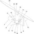
图中:1、连接杆;2、壳体;3、密封盖;4、开口;5、第一固定块;6、第二固定块;7、第一舵机;8、第一驱动轴;9、夹持装置;10、旋转轴;11、第一连接轴;12、第二舵机;13、第二驱动轴;14、第一驱动杆;15、第二连接轴;16、第二驱动杆;17、第三连接轴;18、支撑柱;19、紧固装置;20、驱动电机;21、螺旋叶片;22、防护套。In the figure: 1. Connecting rod; 2. Housing; 3. Sealing cover; 4. Opening; 5. First fixing block; 6. Second fixing block; 7. First steering gear; 8. First drive shaft; 9, clamping device; 10, rotating shaft; 11, first connecting shaft; 12, second steering gear; 13, second driving shaft; 14, first driving rod; 15, second connecting shaft; 16,
具体实施方式Detailed ways
下面将结合本发明实施例中的附图,对本发明实施例中的技术方案进行清楚、完整地描述,显然,所描述的实施例仅仅是本发明一部分实施例,而不是全部的实施例。基于本发明中的实施例,本领域普通技术人员在没有做出创造性劳动前提下所获得的所有其他实施例,都属于本发明保护的范围。The technical solutions in the embodiments of the present invention will be clearly and completely described below with reference to the accompanying drawings in the embodiments of the present invention. Obviously, the described embodiments are only a part of the embodiments of the present invention, but not all of the embodiments. Based on the embodiments of the present invention, all other embodiments obtained by those of ordinary skill in the art without creative efforts shall fall within the protection scope of the present invention.
请参阅图1-3,本发明的一种垂直起降轻型飞机短舱倾转结构,包括连接杆1,连接倾转结构和机体,连接杆1的一端设置有壳体2,起到保护倾转结构的作用,壳体2的顶端安装有密封盖3,壳体2上设置有开口4,支撑柱18由开口4处穿过密封盖3,壳体2内部设置有第一固定块5和第二固定块6,起到固定第一舵机7和第二舵机12的作用,第一固定块5的侧壁上固定设置有第一舵机7,第一舵机7转动控制旋转轴10前后转动,第一舵机7的旋转端设置有第一驱动轴8,传递动力的作用,第一驱动轴8的一端设置有夹持装置9,起到夹持旋转轴10的作用,夹持装置9的中部设置有旋转轴10,旋转轴10运动带动支撑柱18运动,夹持装置9的两侧和旋转轴10之间均设置有第一连接轴11,第二固定块6的侧壁上固定设置有第二舵机12,第二舵机12转动控制旋转轴10左右运动,第二舵机12的旋转端设置有第二驱动轴13,起到传递动力的作用,第二驱动轴13的一端设置有第一驱动杆14,第一驱动杆14底部的顶端设置有第二驱动杆16,第一驱动杆14和第二驱动杆16起到传递动力的作用,第一驱动杆14和第二驱动杆16之间设置有第二连接轴15,第二驱动杆16的顶部和旋转转轴之间设置有第三连接轴17,旋转轴10的顶端固定设置有支撑柱18,起到连接旋转轴10和驱动电机20的作用,支撑柱18的顶部设置有紧固装置19,对防护套22起到紧固的作用,支撑柱18的顶端设置有驱动电机20,驱动电机20转动带动螺旋叶片21转动,驱动电机20的旋转端设置有螺旋叶片21,开口4的顶部设置有防护套22,放置灰尘和水进入到壳体2的内部,防护套22的顶端被紧固装置19固定在支撑柱18上。1-3, a nacelle tilting structure of a vertical take-off and landing light aircraft of the present invention includes a connecting
其中,第一驱动轴8贯穿第一固定块5,第一驱动轴8和第一固定块5之间通过轴承呈转动连接,第一驱动轴8和夹持装置9呈固定连接。The
其中,第二驱动轴13贯穿第二固定块6,第二驱动轴13和第二固定块6之间通过轴承呈转动连接,第二驱动轴13和第一驱动杆14呈固定连接。The
其中,第一连接轴11和夹持装置9、旋转轴10均呈转动连接。Wherein, the first connecting
其中,第二连接轴15和第一驱动杆14、第二驱动杆16均呈转动连接。Wherein, the second connecting
其中,第三连接轴17和第二驱动杆16、旋转轴10均呈转动连接。Wherein, the third connecting
其中,壳体2的外形可以根据空气动力学原理进行设置,壳体2侧壁之间均通过螺栓连接,便于将壳体2拆开对内部的倾转机构进行维修。The shape of the
其中,防护套22的材质为防水性良好的柔性材质,具有良好的防尘和防水功能。Wherein, the material of the
综上所述,该垂直起降轻型飞机短舱倾转结构,在使用时,在飞机飞行时,需要螺旋叶片21前、后倾转时,第一舵机7转动带动夹持装置9和旋转轴10同时转动,支撑柱18带动驱动电机20和螺旋叶片21前后运动,需要螺旋叶片21左、右倾转时,第一舵机7转动带动第一驱动杆14、第二驱动杆16和旋转轴10转动,支撑柱18带动驱动电机20和旋转叶片左、右运动,如果倾转结构发生故障时,可以直接拆开壳体2进行维修和维护。To sum up, the nacelle tilting structure of the vertical take-off and landing light aircraft, when in use, when the aircraft is flying, requires the forward and backward tilting of the
尽管已经示出和描述了本发明的实施例,对于本领域的普通技术人员而言,可以理解在不脱离本发明的原理和精神的情况下可以对这些实施例进行多种变化、修改、替换和变型,本发明的范围由所附权利要求及其等同物限定。Although embodiments of the present invention have been shown and described, it will be understood by those skilled in the art that various changes, modifications, and substitutions can be made in these embodiments without departing from the principle and spirit of the invention and modifications, the scope of the present invention is defined by the appended claims and their equivalents.
Claims (8)
Priority Applications (1)
| Application Number | Priority Date | Filing Date | Title |
|---|---|---|---|
| CN202210931460.0ACN115196012A (en) | 2022-08-04 | 2022-08-04 | Tilting structure of vertical take-off and landing light aircraft nacelle |
Applications Claiming Priority (1)
| Application Number | Priority Date | Filing Date | Title |
|---|---|---|---|
| CN202210931460.0ACN115196012A (en) | 2022-08-04 | 2022-08-04 | Tilting structure of vertical take-off and landing light aircraft nacelle |
Publications (1)
| Publication Number | Publication Date |
|---|---|
| CN115196012Atrue CN115196012A (en) | 2022-10-18 |
Family
ID=83586912
Family Applications (1)
| Application Number | Title | Priority Date | Filing Date |
|---|---|---|---|
| CN202210931460.0APendingCN115196012A (en) | 2022-08-04 | 2022-08-04 | Tilting structure of vertical take-off and landing light aircraft nacelle |
Country Status (1)
| Country | Link |
|---|---|
| CN (1) | CN115196012A (en) |
Citations (6)
| Publication number | Priority date | Publication date | Assignee | Title |
|---|---|---|---|---|
| US20090256026A1 (en)* | 2008-04-11 | 2009-10-15 | Karem Aircraft, Inc. | Tilt Actuation for a Rotorcraft |
| CN101643116A (en)* | 2009-08-03 | 2010-02-10 | 北京航空航天大学 | Tiltrotor controlled by double-propeller vertical duct |
| CN209290672U (en)* | 2018-11-27 | 2019-08-23 | 沈阳无距科技有限公司 | Rotor inclining rotary mechanism and unmanned plane |
| US20200346747A1 (en)* | 2015-11-20 | 2020-11-05 | FlightWave Aerospace Systems | Gimbaled thruster configuration for use with unmanned aerial vehicle |
| CN111891344A (en)* | 2020-08-12 | 2020-11-06 | 天津斑斓航空科技有限公司 | Tandem type tiltable rotor aircraft |
| CN113525679A (en)* | 2021-08-30 | 2021-10-22 | 上海时的科技有限公司 | An electric vertical take-off and landing aircraft structure and its working method |
- 2022
- 2022-08-04CNCN202210931460.0Apatent/CN115196012A/enactivePending
Patent Citations (6)
| Publication number | Priority date | Publication date | Assignee | Title |
|---|---|---|---|---|
| US20090256026A1 (en)* | 2008-04-11 | 2009-10-15 | Karem Aircraft, Inc. | Tilt Actuation for a Rotorcraft |
| CN101643116A (en)* | 2009-08-03 | 2010-02-10 | 北京航空航天大学 | Tiltrotor controlled by double-propeller vertical duct |
| US20200346747A1 (en)* | 2015-11-20 | 2020-11-05 | FlightWave Aerospace Systems | Gimbaled thruster configuration for use with unmanned aerial vehicle |
| CN209290672U (en)* | 2018-11-27 | 2019-08-23 | 沈阳无距科技有限公司 | Rotor inclining rotary mechanism and unmanned plane |
| CN111891344A (en)* | 2020-08-12 | 2020-11-06 | 天津斑斓航空科技有限公司 | Tandem type tiltable rotor aircraft |
| CN113525679A (en)* | 2021-08-30 | 2021-10-22 | 上海时的科技有限公司 | An electric vertical take-off and landing aircraft structure and its working method |
Similar Documents
| Publication | Publication Date | Title |
|---|---|---|
| US20190061963A1 (en) | Hybrid aircraft propulsors having electrically-driven augmentor fans | |
| CN203285619U (en) | Sectional blade and wind power generator | |
| CN211391644U (en) | Underwater robot | |
| CN110884309A (en) | A safe and reliable intelligent drone with online power generation function | |
| CN115196012A (en) | Tilting structure of vertical take-off and landing light aircraft nacelle | |
| CN214776629U (en) | Vector coaxial handheld holder integrated unmanned aerial vehicle | |
| CN206417169U (en) | A kind of unmanned boat integral intelligent linkage propeller | |
| CN118239005A (en) | An integrated ducted fan test bench | |
| CN110712748A (en) | Novel eight-rotor aircraft | |
| CN201320406Y (en) | Oscillating type aero-modeling steering engine | |
| CN215663943U (en) | Vibration reduction type efficient propeller propulsion device for ship | |
| CN211391647U (en) | Solar energy glider pterygoid lamina expandes mechanism under water | |
| CN208360499U (en) | A kind of electronic empennage mechanism of agricultural plant protection unmanned plane | |
| DE2540167A1 (en) | Wind driven ship propulsion - with vertical axis turbines and gearing for linkage shaft to generator and propeller | |
| CN215794436U (en) | Robot device is listened to environment | |
| CN217969917U (en) | Tilting mechanism integrally designed with engine nacelle | |
| CN207157519U (en) | A kind of duct propulsion system based on multi-rotor unmanned aerial vehicle | |
| CN106606871A (en) | Aircraft having flight protection system | |
| CN111532435B (en) | Electric-driven paramotor power device and electric-driven paramotor | |
| CN219595842U (en) | A model airplane with propulsion structure | |
| CN223355933U (en) | Unmanned aerial vehicle is patrolled and examined to fan blade | |
| CN223089448U (en) | A wind-collecting ducted wind turbine | |
| CN221507143U (en) | Ultrasonic multi-base sound buoy detection device | |
| CN217950769U (en) | Turbocharging ducted fan | |
| CN222062247U (en) | Electric propulsion equipment |
Legal Events
| Date | Code | Title | Description |
|---|---|---|---|
| PB01 | Publication | ||
| PB01 | Publication | ||
| SE01 | Entry into force of request for substantive examination | ||
| SE01 | Entry into force of request for substantive examination |