CN115192898A - Ventricular assist device - Google Patents
Ventricular assist deviceDownload PDFInfo
- Publication number
- CN115192898A CN115192898ACN202210587598.3ACN202210587598ACN115192898ACN 115192898 ACN115192898 ACN 115192898ACN 202210587598 ACN202210587598 ACN 202210587598ACN 115192898 ACN115192898 ACN 115192898A
- Authority
- CN
- China
- Prior art keywords
- impeller
- frame
- tube
- applications
- typically
- Prior art date
- Legal status (The legal status is an assumption and is not a legal conclusion. Google has not performed a legal analysis and makes no representation as to the accuracy of the status listed.)
- Pending
Links
Images


Classifications
- A—HUMAN NECESSITIES
- A61—MEDICAL OR VETERINARY SCIENCE; HYGIENE
- A61M—DEVICES FOR INTRODUCING MEDIA INTO, OR ONTO, THE BODY; DEVICES FOR TRANSDUCING BODY MEDIA OR FOR TAKING MEDIA FROM THE BODY; DEVICES FOR PRODUCING OR ENDING SLEEP OR STUPOR
- A61M60/00—Blood pumps; Devices for mechanical circulatory actuation; Balloon pumps for circulatory assistance
- A61M60/10—Location thereof with respect to the patient's body
- A61M60/122—Implantable pumps or pumping devices, i.e. the blood being pumped inside the patient's body
- A61M60/126—Implantable pumps or pumping devices, i.e. the blood being pumped inside the patient's body implantable via, into, inside, in line, branching on, or around a blood vessel
- A61M60/148—Implantable pumps or pumping devices, i.e. the blood being pumped inside the patient's body implantable via, into, inside, in line, branching on, or around a blood vessel in line with a blood vessel using resection or like techniques, e.g. permanent endovascular heart assist devices
- A—HUMAN NECESSITIES
- A61—MEDICAL OR VETERINARY SCIENCE; HYGIENE
- A61M—DEVICES FOR INTRODUCING MEDIA INTO, OR ONTO, THE BODY; DEVICES FOR TRANSDUCING BODY MEDIA OR FOR TAKING MEDIA FROM THE BODY; DEVICES FOR PRODUCING OR ENDING SLEEP OR STUPOR
- A61M60/00—Blood pumps; Devices for mechanical circulatory actuation; Balloon pumps for circulatory assistance
- A61M60/10—Location thereof with respect to the patient's body
- A61M60/122—Implantable pumps or pumping devices, i.e. the blood being pumped inside the patient's body
- A61M60/126—Implantable pumps or pumping devices, i.e. the blood being pumped inside the patient's body implantable via, into, inside, in line, branching on, or around a blood vessel
- A61M60/13—Implantable pumps or pumping devices, i.e. the blood being pumped inside the patient's body implantable via, into, inside, in line, branching on, or around a blood vessel by means of a catheter allowing explantation, e.g. catheter pumps temporarily introduced via the vascular system
- A—HUMAN NECESSITIES
- A61—MEDICAL OR VETERINARY SCIENCE; HYGIENE
- A61M—DEVICES FOR INTRODUCING MEDIA INTO, OR ONTO, THE BODY; DEVICES FOR TRANSDUCING BODY MEDIA OR FOR TAKING MEDIA FROM THE BODY; DEVICES FOR PRODUCING OR ENDING SLEEP OR STUPOR
- A61M60/00—Blood pumps; Devices for mechanical circulatory actuation; Balloon pumps for circulatory assistance
- A61M60/10—Location thereof with respect to the patient's body
- A61M60/122—Implantable pumps or pumping devices, i.e. the blood being pumped inside the patient's body
- A61M60/126—Implantable pumps or pumping devices, i.e. the blood being pumped inside the patient's body implantable via, into, inside, in line, branching on, or around a blood vessel
- A61M60/135—Implantable pumps or pumping devices, i.e. the blood being pumped inside the patient's body implantable via, into, inside, in line, branching on, or around a blood vessel inside a blood vessel, e.g. using grafting
- A61M60/139—Implantable pumps or pumping devices, i.e. the blood being pumped inside the patient's body implantable via, into, inside, in line, branching on, or around a blood vessel inside a blood vessel, e.g. using grafting inside the aorta, e.g. intra-aortic balloon pumps
- A—HUMAN NECESSITIES
- A61—MEDICAL OR VETERINARY SCIENCE; HYGIENE
- A61M—DEVICES FOR INTRODUCING MEDIA INTO, OR ONTO, THE BODY; DEVICES FOR TRANSDUCING BODY MEDIA OR FOR TAKING MEDIA FROM THE BODY; DEVICES FOR PRODUCING OR ENDING SLEEP OR STUPOR
- A61M60/00—Blood pumps; Devices for mechanical circulatory actuation; Balloon pumps for circulatory assistance
- A61M60/10—Location thereof with respect to the patient's body
- A61M60/122—Implantable pumps or pumping devices, i.e. the blood being pumped inside the patient's body
- A61M60/165—Implantable pumps or pumping devices, i.e. the blood being pumped inside the patient's body implantable in, on, or around the heart
- A61M60/17—Implantable pumps or pumping devices, i.e. the blood being pumped inside the patient's body implantable in, on, or around the heart inside a ventricle, e.g. intraventricular balloon pumps
- A61M60/174—Implantable pumps or pumping devices, i.e. the blood being pumped inside the patient's body implantable in, on, or around the heart inside a ventricle, e.g. intraventricular balloon pumps discharging the blood to the ventricle or arterial system via a cannula internal to the ventricle or arterial system
- A—HUMAN NECESSITIES
- A61—MEDICAL OR VETERINARY SCIENCE; HYGIENE
- A61M—DEVICES FOR INTRODUCING MEDIA INTO, OR ONTO, THE BODY; DEVICES FOR TRANSDUCING BODY MEDIA OR FOR TAKING MEDIA FROM THE BODY; DEVICES FOR PRODUCING OR ENDING SLEEP OR STUPOR
- A61M60/00—Blood pumps; Devices for mechanical circulatory actuation; Balloon pumps for circulatory assistance
- A61M60/20—Type thereof
- A61M60/205—Non-positive displacement blood pumps
- A61M60/216—Non-positive displacement blood pumps including a rotating member acting on the blood, e.g. impeller
- A61M60/237—Non-positive displacement blood pumps including a rotating member acting on the blood, e.g. impeller the blood flow through the rotating member having mainly axial components, e.g. axial flow pumps
- A—HUMAN NECESSITIES
- A61—MEDICAL OR VETERINARY SCIENCE; HYGIENE
- A61M—DEVICES FOR INTRODUCING MEDIA INTO, OR ONTO, THE BODY; DEVICES FOR TRANSDUCING BODY MEDIA OR FOR TAKING MEDIA FROM THE BODY; DEVICES FOR PRODUCING OR ENDING SLEEP OR STUPOR
- A61M60/00—Blood pumps; Devices for mechanical circulatory actuation; Balloon pumps for circulatory assistance
- A61M60/40—Details relating to driving
- A61M60/403—Details relating to driving for non-positive displacement blood pumps
- A61M60/408—Details relating to driving for non-positive displacement blood pumps the force acting on the blood contacting member being mechanical, e.g. transmitted by a shaft or cable
- A61M60/411—Details relating to driving for non-positive displacement blood pumps the force acting on the blood contacting member being mechanical, e.g. transmitted by a shaft or cable generated by an electromotor
- A61M60/414—Details relating to driving for non-positive displacement blood pumps the force acting on the blood contacting member being mechanical, e.g. transmitted by a shaft or cable generated by an electromotor transmitted by a rotating cable, e.g. for blood pumps mounted on a catheter
- A—HUMAN NECESSITIES
- A61—MEDICAL OR VETERINARY SCIENCE; HYGIENE
- A61M—DEVICES FOR INTRODUCING MEDIA INTO, OR ONTO, THE BODY; DEVICES FOR TRANSDUCING BODY MEDIA OR FOR TAKING MEDIA FROM THE BODY; DEVICES FOR PRODUCING OR ENDING SLEEP OR STUPOR
- A61M60/00—Blood pumps; Devices for mechanical circulatory actuation; Balloon pumps for circulatory assistance
- A61M60/40—Details relating to driving
- A61M60/403—Details relating to driving for non-positive displacement blood pumps
- A61M60/419—Details relating to driving for non-positive displacement blood pumps the force acting on the blood contacting member being permanent magnetic, e.g. from a rotating magnetic coupling between driving and driven magnets
- A—HUMAN NECESSITIES
- A61—MEDICAL OR VETERINARY SCIENCE; HYGIENE
- A61M—DEVICES FOR INTRODUCING MEDIA INTO, OR ONTO, THE BODY; DEVICES FOR TRANSDUCING BODY MEDIA OR FOR TAKING MEDIA FROM THE BODY; DEVICES FOR PRODUCING OR ENDING SLEEP OR STUPOR
- A61M60/00—Blood pumps; Devices for mechanical circulatory actuation; Balloon pumps for circulatory assistance
- A61M60/40—Details relating to driving
- A61M60/403—Details relating to driving for non-positive displacement blood pumps
- A61M60/422—Details relating to driving for non-positive displacement blood pumps the force acting on the blood contacting member being electromagnetic, e.g. using canned motor pumps
- A—HUMAN NECESSITIES
- A61—MEDICAL OR VETERINARY SCIENCE; HYGIENE
- A61M—DEVICES FOR INTRODUCING MEDIA INTO, OR ONTO, THE BODY; DEVICES FOR TRANSDUCING BODY MEDIA OR FOR TAKING MEDIA FROM THE BODY; DEVICES FOR PRODUCING OR ENDING SLEEP OR STUPOR
- A61M60/00—Blood pumps; Devices for mechanical circulatory actuation; Balloon pumps for circulatory assistance
- A61M60/50—Details relating to control
- A61M60/508—Electronic control means, e.g. for feedback regulation
- A61M60/515—Regulation using real-time patient data
- A61M60/531—Regulation using real-time patient data using blood pressure data, e.g. from blood pressure sensors
- A—HUMAN NECESSITIES
- A61—MEDICAL OR VETERINARY SCIENCE; HYGIENE
- A61M—DEVICES FOR INTRODUCING MEDIA INTO, OR ONTO, THE BODY; DEVICES FOR TRANSDUCING BODY MEDIA OR FOR TAKING MEDIA FROM THE BODY; DEVICES FOR PRODUCING OR ENDING SLEEP OR STUPOR
- A61M60/00—Blood pumps; Devices for mechanical circulatory actuation; Balloon pumps for circulatory assistance
- A61M60/80—Constructional details other than related to driving
- A61M60/802—Constructional details other than related to driving of non-positive displacement blood pumps
- A61M60/804—Impellers
- A61M60/806—Vanes or blades
- A61M60/808—Vanes or blades specially adapted for deformable impellers, e.g. expandable impellers
- A—HUMAN NECESSITIES
- A61—MEDICAL OR VETERINARY SCIENCE; HYGIENE
- A61M—DEVICES FOR INTRODUCING MEDIA INTO, OR ONTO, THE BODY; DEVICES FOR TRANSDUCING BODY MEDIA OR FOR TAKING MEDIA FROM THE BODY; DEVICES FOR PRODUCING OR ENDING SLEEP OR STUPOR
- A61M60/00—Blood pumps; Devices for mechanical circulatory actuation; Balloon pumps for circulatory assistance
- A61M60/80—Constructional details other than related to driving
- A61M60/802—Constructional details other than related to driving of non-positive displacement blood pumps
- A61M60/81—Pump housings
- A61M60/812—Vanes or blades, e.g. static flow guides
- A—HUMAN NECESSITIES
- A61—MEDICAL OR VETERINARY SCIENCE; HYGIENE
- A61M—DEVICES FOR INTRODUCING MEDIA INTO, OR ONTO, THE BODY; DEVICES FOR TRANSDUCING BODY MEDIA OR FOR TAKING MEDIA FROM THE BODY; DEVICES FOR PRODUCING OR ENDING SLEEP OR STUPOR
- A61M60/00—Blood pumps; Devices for mechanical circulatory actuation; Balloon pumps for circulatory assistance
- A61M60/80—Constructional details other than related to driving
- A61M60/802—Constructional details other than related to driving of non-positive displacement blood pumps
- A61M60/81—Pump housings
- A61M60/816—Sensors arranged on or in the housing, e.g. ultrasound flow sensors
- A—HUMAN NECESSITIES
- A61—MEDICAL OR VETERINARY SCIENCE; HYGIENE
- A61M—DEVICES FOR INTRODUCING MEDIA INTO, OR ONTO, THE BODY; DEVICES FOR TRANSDUCING BODY MEDIA OR FOR TAKING MEDIA FROM THE BODY; DEVICES FOR PRODUCING OR ENDING SLEEP OR STUPOR
- A61M60/00—Blood pumps; Devices for mechanical circulatory actuation; Balloon pumps for circulatory assistance
- A61M60/80—Constructional details other than related to driving
- A61M60/802—Constructional details other than related to driving of non-positive displacement blood pumps
- A61M60/818—Bearings
- A61M60/825—Contact bearings, e.g. ball-and-cup or pivot bearings
- A—HUMAN NECESSITIES
- A61—MEDICAL OR VETERINARY SCIENCE; HYGIENE
- A61M—DEVICES FOR INTRODUCING MEDIA INTO, OR ONTO, THE BODY; DEVICES FOR TRANSDUCING BODY MEDIA OR FOR TAKING MEDIA FROM THE BODY; DEVICES FOR PRODUCING OR ENDING SLEEP OR STUPOR
- A61M60/00—Blood pumps; Devices for mechanical circulatory actuation; Balloon pumps for circulatory assistance
- A61M60/80—Constructional details other than related to driving
- A61M60/802—Constructional details other than related to driving of non-positive displacement blood pumps
- A61M60/827—Sealings between moving parts
- A61M60/829—Sealings between moving parts having a purge fluid supply
- A—HUMAN NECESSITIES
- A61—MEDICAL OR VETERINARY SCIENCE; HYGIENE
- A61M—DEVICES FOR INTRODUCING MEDIA INTO, OR ONTO, THE BODY; DEVICES FOR TRANSDUCING BODY MEDIA OR FOR TAKING MEDIA FROM THE BODY; DEVICES FOR PRODUCING OR ENDING SLEEP OR STUPOR
- A61M60/00—Blood pumps; Devices for mechanical circulatory actuation; Balloon pumps for circulatory assistance
- A61M60/80—Constructional details other than related to driving
- A61M60/855—Constructional details other than related to driving of implantable pumps or pumping devices
- A61M60/857—Implantable blood tubes
- A—HUMAN NECESSITIES
- A61—MEDICAL OR VETERINARY SCIENCE; HYGIENE
- A61M—DEVICES FOR INTRODUCING MEDIA INTO, OR ONTO, THE BODY; DEVICES FOR TRANSDUCING BODY MEDIA OR FOR TAKING MEDIA FROM THE BODY; DEVICES FOR PRODUCING OR ENDING SLEEP OR STUPOR
- A61M60/00—Blood pumps; Devices for mechanical circulatory actuation; Balloon pumps for circulatory assistance
- A61M60/80—Constructional details other than related to driving
- A61M60/855—Constructional details other than related to driving of implantable pumps or pumping devices
- A61M60/865—Devices for guiding or inserting pumps or pumping devices into the patient's body
- A—HUMAN NECESSITIES
- A61—MEDICAL OR VETERINARY SCIENCE; HYGIENE
- A61M—DEVICES FOR INTRODUCING MEDIA INTO, OR ONTO, THE BODY; DEVICES FOR TRANSDUCING BODY MEDIA OR FOR TAKING MEDIA FROM THE BODY; DEVICES FOR PRODUCING OR ENDING SLEEP OR STUPOR
- A61M60/00—Blood pumps; Devices for mechanical circulatory actuation; Balloon pumps for circulatory assistance
- A61M60/80—Constructional details other than related to driving
- A61M60/855—Constructional details other than related to driving of implantable pumps or pumping devices
- A61M60/89—Valves
- A61M60/894—Passive valves, i.e. valves actuated by the blood
- A61M60/896—Passive valves, i.e. valves actuated by the blood having flexible or resilient parts, e.g. flap valves
- B—PERFORMING OPERATIONS; TRANSPORTING
- B05—SPRAYING OR ATOMISING IN GENERAL; APPLYING FLUENT MATERIALS TO SURFACES, IN GENERAL
- B05D—PROCESSES FOR APPLYING FLUENT MATERIALS TO SURFACES, IN GENERAL
- B05D1/00—Processes for applying liquids or other fluent materials
- B05D1/02—Processes for applying liquids or other fluent materials performed by spraying
- F—MECHANICAL ENGINEERING; LIGHTING; HEATING; WEAPONS; BLASTING
- F04—POSITIVE - DISPLACEMENT MACHINES FOR LIQUIDS; PUMPS FOR LIQUIDS OR ELASTIC FLUIDS
- F04D—NON-POSITIVE-DISPLACEMENT PUMPS
- F04D29/00—Details, component parts, or accessories
- F04D29/26—Rotors specially for elastic fluids
- F04D29/32—Rotors specially for elastic fluids for axial flow pumps
- F04D29/38—Blades
- F04D29/382—Flexible blades
- F—MECHANICAL ENGINEERING; LIGHTING; HEATING; WEAPONS; BLASTING
- F04—POSITIVE - DISPLACEMENT MACHINES FOR LIQUIDS; PUMPS FOR LIQUIDS OR ELASTIC FLUIDS
- F04D—NON-POSITIVE-DISPLACEMENT PUMPS
- F04D29/00—Details, component parts, or accessories
- F04D29/40—Casings; Connections of working fluid
- F04D29/52—Casings; Connections of working fluid for axial pumps
- F04D29/522—Casings; Connections of working fluid for axial pumps especially adapted for elastic fluid pumps
- F04D29/526—Details of the casing section radially opposing blade tips
- F—MECHANICAL ENGINEERING; LIGHTING; HEATING; WEAPONS; BLASTING
- F04—POSITIVE - DISPLACEMENT MACHINES FOR LIQUIDS; PUMPS FOR LIQUIDS OR ELASTIC FLUIDS
- F04D—NON-POSITIVE-DISPLACEMENT PUMPS
- F04D29/00—Details, component parts, or accessories
- F04D29/40—Casings; Connections of working fluid
- F04D29/52—Casings; Connections of working fluid for axial pumps
- F04D29/54—Fluid-guiding means, e.g. diffusers
- F04D29/541—Specially adapted for elastic fluid pumps
- F04D29/545—Ducts
- A—HUMAN NECESSITIES
- A61—MEDICAL OR VETERINARY SCIENCE; HYGIENE
- A61M—DEVICES FOR INTRODUCING MEDIA INTO, OR ONTO, THE BODY; DEVICES FOR TRANSDUCING BODY MEDIA OR FOR TAKING MEDIA FROM THE BODY; DEVICES FOR PRODUCING OR ENDING SLEEP OR STUPOR
- A61M2205/00—General characteristics of the apparatus
- A61M2205/02—General characteristics of the apparatus characterised by a particular materials
- A61M2205/0216—Materials providing elastic properties, e.g. for facilitating deformation and avoid breaking
- A—HUMAN NECESSITIES
- A61—MEDICAL OR VETERINARY SCIENCE; HYGIENE
- A61M—DEVICES FOR INTRODUCING MEDIA INTO, OR ONTO, THE BODY; DEVICES FOR TRANSDUCING BODY MEDIA OR FOR TAKING MEDIA FROM THE BODY; DEVICES FOR PRODUCING OR ENDING SLEEP OR STUPOR
- A61M2205/00—General characteristics of the apparatus
- A61M2205/33—Controlling, regulating or measuring
- A61M2205/3331—Pressure; Flow
- A61M2205/3344—Measuring or controlling pressure at the body treatment site
- A—HUMAN NECESSITIES
- A61—MEDICAL OR VETERINARY SCIENCE; HYGIENE
- A61M—DEVICES FOR INTRODUCING MEDIA INTO, OR ONTO, THE BODY; DEVICES FOR TRANSDUCING BODY MEDIA OR FOR TAKING MEDIA FROM THE BODY; DEVICES FOR PRODUCING OR ENDING SLEEP OR STUPOR
- A61M2230/00—Measuring parameters of the user
- A61M2230/30—Blood pressure
- A—HUMAN NECESSITIES
- A61—MEDICAL OR VETERINARY SCIENCE; HYGIENE
- A61M—DEVICES FOR INTRODUCING MEDIA INTO, OR ONTO, THE BODY; DEVICES FOR TRANSDUCING BODY MEDIA OR FOR TAKING MEDIA FROM THE BODY; DEVICES FOR PRODUCING OR ENDING SLEEP OR STUPOR
- A61M60/00—Blood pumps; Devices for mechanical circulatory actuation; Balloon pumps for circulatory assistance
- A61M60/10—Location thereof with respect to the patient's body
- A61M60/122—Implantable pumps or pumping devices, i.e. the blood being pumped inside the patient's body
- A—HUMAN NECESSITIES
- A61—MEDICAL OR VETERINARY SCIENCE; HYGIENE
- A61M—DEVICES FOR INTRODUCING MEDIA INTO, OR ONTO, THE BODY; DEVICES FOR TRANSDUCING BODY MEDIA OR FOR TAKING MEDIA FROM THE BODY; DEVICES FOR PRODUCING OR ENDING SLEEP OR STUPOR
- A61M60/00—Blood pumps; Devices for mechanical circulatory actuation; Balloon pumps for circulatory assistance
- A61M60/20—Type thereof
- A61M60/205—Non-positive displacement blood pumps
- A—HUMAN NECESSITIES
- A61—MEDICAL OR VETERINARY SCIENCE; HYGIENE
- A61M—DEVICES FOR INTRODUCING MEDIA INTO, OR ONTO, THE BODY; DEVICES FOR TRANSDUCING BODY MEDIA OR FOR TAKING MEDIA FROM THE BODY; DEVICES FOR PRODUCING OR ENDING SLEEP OR STUPOR
- A61M60/00—Blood pumps; Devices for mechanical circulatory actuation; Balloon pumps for circulatory assistance
- A61M60/80—Constructional details other than related to driving
- A61M60/802—Constructional details other than related to driving of non-positive displacement blood pumps
- A61M60/804—Impellers
Landscapes
- Health & Medical Sciences (AREA)
- Engineering & Computer Science (AREA)
- Heart & Thoracic Surgery (AREA)
- Cardiology (AREA)
- Mechanical Engineering (AREA)
- Life Sciences & Earth Sciences (AREA)
- Biomedical Technology (AREA)
- Hematology (AREA)
- Anesthesiology (AREA)
- Animal Behavior & Ethology (AREA)
- General Health & Medical Sciences (AREA)
- Public Health (AREA)
- Veterinary Medicine (AREA)
- Vascular Medicine (AREA)
- General Engineering & Computer Science (AREA)
- Transplantation (AREA)
- Medical Informatics (AREA)
- External Artificial Organs (AREA)
Abstract
Description
Translated fromChinese本申请是申请日为2020年01月23日,申请号为202080017728.9,发明名称为“心室辅助装置”的申请的分案申请。This application is a divisional application with an application date of January 23, 2020, an application number of 202080017728.9, and the title of the invention is "ventricular assist device".
相关申请的交叉引用CROSS-REFERENCE TO RELATED APPLICATIONS
本申请要求下列项目的优先权:This application claims priority to:
Tuval于2019年1月24日提交的题为“Ventricular assist device(心室辅助装置)”的美国临时专利申请62/796,138;U.S.
Tuval于2019年5月23日提交的题为“Ventricular assist device(心室辅助装置)”的美国临时专利申请62/851,716;U.S.
Tuval于2019年7月5日提交的题为“Ventricular assist device(心室辅助装置)”的美国临时专利申请62/870,821;和U.S.
Tuval于2019年9月5日提交的题为“Ventricular assist device(心室辅助装置)”的美国临时专利申请62/896,026。U.S.
本申请涉及与本申请同日提交的题为“Distal tip element for a ventricularassist device(用于心室辅助装置的远侧尖端元件)”的美国申请,其要求上述美国临时申请的优先权。This application is related to US application entitled "Distal tip element for a ventricular assist device", filed on the same date as this application, which claims priority to the aforementioned US provisional application.
所有这些上述引用的申请全部通过引用并入本文。All of these above-referenced applications are incorporated herein by reference in their entirety.
发明实施例的领域Field of Invention Embodiments
本发明的一些应用总体上涉及医疗器械。具体地,本发明的一些应用涉及心室辅助装置及其使用方法。Some applications of the present invention relate generally to medical devices. In particular, some applications of the present invention relate to ventricular assist devices and methods of use thereof.
背景background
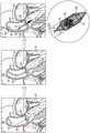
心室辅助装置是机械循环支持装置,其被设计为辅助心腔并卸载心腔负荷,以维持或增加心输出量。这些心室辅助装置用于患有心力衰竭的病人和在经皮冠脉介入治疗期间有心功能恶化风险的病人。最常见的是,左心室辅助装置施用于有缺陷的心脏,以辅助左心室功能。在一些情况下,使用右心室辅助装置以辅助右心室功能。这种辅助装置或被设计成永久植入,或被安装在导管上以便临时放置。Ventricular assist devices are mechanical circulatory support devices designed to assist and unload cardiac chambers in order to maintain or increase cardiac output. These ventricular assist devices are used in patients with heart failure and those at risk of worsening cardiac function during percutaneous coronary intervention. Most commonly, left ventricular assist devices are administered to the defective heart to assist left ventricular function. In some cases, a right ventricular assist device is used to assist right ventricular function. Such assistive devices are either designed to be implanted permanently or mounted on a catheter for temporary placement.
实施例概述Example overview
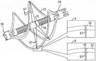
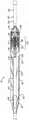
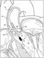
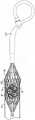
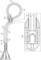
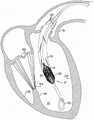
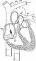
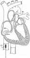
根据本发明的一些应用,心室辅助装置包括设置在轴向轴杆(axial shaft)上的叶轮,其中框架围绕叶轮设置。典型地,心室辅助装置包括穿过受试者的主动脉瓣的管,使得管的近端被设置在受试者的主动脉内,并且管的远端被设置在受试者的左心室内。叶轮、轴向轴杆和框架被设置在管的位于受试者的左心室内的远侧部分内。典型地,叶轮被配置成通过旋转将血液从左心室泵入主动脉。典型地,管在管的远端处限定一个或更多个血液入口开口,在叶轮运行期间,血液经由该血液入口开口从左心室流入到管中。对于一些应用,管的近侧部分限定一个或更多个血液出口开口,在叶轮运行期间,血液经由该血液出口开口从管流入升主动脉。According to some applications of the invention, a ventricular assist device includes an impeller disposed on an axial shaft, wherein a frame is disposed around the impeller. Typically, a ventricular assist device includes a tube passing through the subject's aortic valve such that the proximal end of the tube is positioned within the subject's aorta and the distal end of the tube is positioned within the subject's left ventricle . The impeller, axial shaft and frame are positioned within the distal portion of the tube located within the left ventricle of the subject. Typically, the impeller is configured to pump blood from the left ventricle into the aorta by rotation. Typically, the tube defines one or more blood inlet openings at the distal end of the tube through which blood flows from the left ventricle into the tube during operation of the impeller. For some applications, the proximal portion of the tube defines one or more blood outlet openings through which blood flows from the tube into the ascending aorta during operation of the impeller.
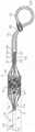
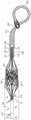
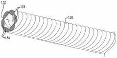
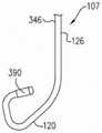
对于一些应用,心室辅助装置包括远侧尖端元件,该远侧尖端元件被配置成限定平直的近侧部分和弯曲的远侧部分,该平直的近侧部分限定纵向轴线,该弯曲的远侧部分被成形为在经过拐点并且相对于平直的近侧部分的纵向轴线在第二方向上弯曲之前相对于平直的近侧部分的纵向轴线在第一方向上弯曲,使得弯曲的远侧部分在平直的近侧部分的纵向轴线的一侧上限定隆起部。典型地,远侧尖端元件具有问号形状和/或网球拍形状。For some applications, the ventricular assist device includes a distal tip element configured to define a flat proximal portion and a curved distal portion, the flat proximal portion defining a longitudinal axis, the curved distal portion The side portion is shaped to bend in a first direction relative to the longitudinal axis of the flat proximal portion prior to passing the inflection point and bending in the second direction relative to the longitudinal axis of the flat proximal portion such that the curved distal The portion defines a ridge on one side of the longitudinal axis of the flat proximal portion. Typically, the distal tip element has a question mark shape and/or a tennis racket shape.
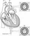
对于一些应用,远侧尖端元件被配置为当远侧尖端元件抵靠受试者的左心室的顶点放置时,将血液入口开口与受试者的左心室的后壁分隔开。典型地,远侧尖端元件被配置为当远侧尖端元件接触受试者的左心室的顶点时,将血液入口开口与受试者的左心室的隔膜壁分隔开。更典型地,远侧尖端元件被配置成使得当远侧尖端元件被插入左心室使得隆起部朝向隔膜壁隆起时,响应于远侧尖端元件被推靠在受试者的左心室的顶点,血液入口开口被推离隔膜壁并且被推向受试者的左心室的自由壁。对于一些应用,通过远侧尖端元件的平直的近侧部分绕远侧尖端元件的弯曲的远侧部分枢转,血液入口开口被推离隔膜壁并且被推向受试者的左心室的自由壁。For some applications, the distal tip element is configured to separate the blood inlet opening from the posterior wall of the subject's left ventricle when the distal tip element is placed against the apex of the subject's left ventricle. Typically, the distal tip element is configured to separate the blood inlet opening from the septal wall of the subject's left ventricle when the distal tip element contacts the apex of the subject's left ventricle. More typically, the distal tip element is configured such that when the distal tip element is inserted into the left ventricle such that the bulge bulges toward the septal wall, in response to the distal tip element being pushed against the apex of the left ventricle of the subject, blood The inlet opening is pushed away from the septal wall and toward the free wall of the subject's left ventricle. For some applications, the blood inlet opening is pushed away from the septum wall and toward the free wall of the subject's left ventricle by pivoting the flat proximal portion of the distal tip element about the curved distal portion of the distal tip element .
对于一些应用,鸭嘴阀被设置在远侧尖端元件的最远侧10mm内。典型地,鸭嘴阀限定宽入口和窄尖端,窄尖端限定穿过其中的缝隙,鸭嘴阀面向近侧,使得宽入口面向远侧尖端元件的远端,并且使得窄尖端背离远侧尖端元件的远端。对于一些应用,心室辅助装置被配置成与导引线一起使用,并且远侧尖端元件限定导引线内腔。对于一些这样的应用,心室辅助装置还包括导引线引导件,该导引线引导件被设置在导引线内腔内近侧于鸭嘴阀的位置。典型地,导引线引导件被成形为限定穿过其中的孔,该孔的直径从导引线引导件的近端到导引线引导件的远端变窄,导引线引导件的形状被配置为当导引线从左心室辅助装置的近端插入时,朝向鸭嘴阀的窄近端处的缝隙来引导导引线的尖端。对于一些应用,鸭嘴阀被成形为在其近端处限定会聚导引部分,该会聚导引部分朝向缝隙会聚,使得导引部分被配置成朝向缝隙进一步引导导引线的尖端。For some applications, the duckbill valve is positioned within the most distal 10 mm of the distal tip element. Typically, the duckbill valve defines a wide inlet and a narrow tip, the narrow tip defines a slit therethrough, the duckbill valve faces proximally such that the wide inlet faces the distal end of the distal tip element and the narrow tip faces away from the distal tip element the far end. For some applications, the ventricular assist device is configured for use with a guide wire, and the distal tip element defines a guide wire lumen. For some such applications, the ventricular assist device further includes a guidewire guide disposed within the guidewire lumen proximal to the duckbill valve. Typically, the guidewire guide is shaped to define a hole therethrough that narrows in diameter from the proximal end of the guidewire guide to the distal end of the guidewire guide, the shape of the guidewire guide is configured to guide the tip of the guide wire toward the slit at the narrow proximal end of the duckbill valve when the guide wire is inserted from the proximal end of the left ventricular assist device. For some applications, the duckbill valve is shaped to define a converging guide portion at its proximal end that converges toward the slit, such that the guide portion is configured to further guide the tip of the guide wire toward the slit.
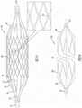
典型地,围绕叶轮设置的框架限定多个单元格,并且框架被配置成使得在框架的非径向约束构型中,框架包括大致柱形部分。更典型地,柱形部分内的每个单元格围绕柱形部分的圆周测量的宽度小于2mm(例如,1.4mm-1.6mm,或1.6mm-1.8mm)。对于一些应用,内衬至少衬在框架的柱形部分上,并且叶轮被设置在框架内,使得在叶轮的非径向约束构型中,在叶轮跨度最大的位置处,叶轮被设置在框架的柱形部分内,使得叶轮的外边缘与内衬之间的间隙小于1mm(例如,小于0.4mm)。典型地,叶轮被配置为旋转,以便将血液从左心室泵送到主动脉,并且被配置为相对于框架是稳定的,使得在叶轮旋转期间,叶轮的外边缘与内衬之间的间隙得以保持并且基本上恒定。对于一些应用,与叶轮相对于框架不稳定的情况相比,叶轮被配置为通过相对于框架被稳定来降低溶血的风险。Typically, a frame disposed about the impeller defines a plurality of cells, and the frame is configured such that in the non-radially constrained configuration of the frame, the frame includes a generally cylindrical portion. More typically, each cell within the cylindrical portion has a width measured around the circumference of the cylindrical portion less than 2 mm (eg, 1.4 mm-1.6 mm, or 1.6 mm-1.8 mm). For some applications, the liner lines at least the cylindrical portion of the frame, and the impeller is positioned within the frame, such that in the non-radially constrained configuration of the impeller, the impeller is positioned on the side of the frame where the impeller span is greatest inside the cylindrical portion such that the gap between the outer edge of the impeller and the inner liner is less than 1 mm (eg, less than 0.4 mm). Typically, the impeller is configured to rotate to pump blood from the left ventricle to the aorta, and is configured to be stable relative to the frame such that during rotation of the impeller, the gap between the outer edge of the impeller and the liner is freed maintained and substantially constant. For some applications, the impeller is configured to reduce the risk of hemolysis by being stabilized relative to the frame as compared to a situation where the impeller is unstable relative to the frame.
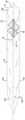
对于一些应用,近侧径向支承件和远侧径向支承件分别被设置在框架的近端和远端处,并且轴向轴杆穿过近侧径向支承件和远侧径向支承件。典型地,通过相对于轴向轴杆将叶轮保持在径向固定位置并且轴向轴杆是刚性的而使叶轮相对于框架稳定。对于一些应用,叶轮包括围绕轴向轴杆设置的衬套,并且这些衬套中的至少一个衬套被配置成相对于轴向轴杆是可滑动的。对于一些应用,叶轮由沿着轴向轴杆的以下区域相对于框架得以稳定,在该区域上,至少一个衬套被配置为相对于轴向轴杆是可滑动的,该区域被涂覆以通过减小至少一个衬套与叶轮之间的间隙来基本上防止叶轮振动。例如,该区域可以被涂覆类金刚石碳涂层、聚四氟乙烯涂层和/或聚合物套筒。For some applications, proximal and distal radial supports are provided at the proximal and distal ends of the frame, respectively, and the axial shaft passes through the proximal and distal radial supports . Typically, the impeller is stabilized relative to the frame by holding the impeller in a radially fixed position relative to the axial shaft and the axial shaft being rigid. For some applications, the impeller includes bushings disposed about the axial shaft, and at least one of the bushings is configured to be slidable relative to the axial shaft. For some applications, the impeller is stabilized relative to the frame by an area along the axial shaft on which at least one bushing is configured to be slidable relative to the axial shaft, the area being coated with The impeller vibration is substantially prevented by reducing the clearance between the at least one bushing and the impeller. For example, the region may be coated with a diamond-like carbon coating, a Teflon coating, and/or a polymer sleeve.
对于一些应用,框架限定支柱,这些支柱具有的结构使得当框架从框架的近端向框架的中心过渡时,支柱经过接合部,在接合部处成对支柱以Y形形式从单个支柱分支出来。典型地,框架的支柱的结构被配置,使得响应于递送导管的远端和框架被移动到相对于彼此重叠的位置(例如,通过递送导管的远端在框架上被推进,或者通过框架缩回到递送导管的远端内),框架被配置成通过变得轴向伸长而呈现其径向约束构型,并且被配置成通过变得轴向伸长而使得叶轮呈现其径向约束构型(例如,通过从每个接合部分支出来的成对支柱被配置成绕接合部枢转并且彼此更靠近地移动,从而响应于递送导管的远端和框架被移动到相对于彼此重叠的位置而闭合)。For some applications, the frame defines struts structured such that as the frame transitions from the proximal end of the frame to the center of the frame, the struts pass through a junction where pairs of struts branch off a single strut in a Y-shape. Typically, the struts of the frame are configured such that in response to the distal end of the delivery catheter and the frame being moved into overlapping positions relative to each other (eg, by being advanced on the frame by the distal end of the delivery catheter, or retracted by the frame) into the distal end of the delivery catheter), the frame is configured to assume its radially constrained configuration by becoming axially elongated, and is configured to cause the impeller to assume its radially constrained configuration by becoming axially elongated (eg, responsive to the distal end of the delivery catheter and the frame being moved into overlapping positions relative to each other, by a pair of struts emanating from each junction being configured to pivot about the junction and move closer to each other) closure).
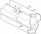
对于一些应用,用于血泵的叶轮的壳体通过执行以下步骤来制造。围绕芯轴放置内衬。围绕内衬放置框架的柱形部分,框架的柱形部分包括支柱,这些支柱限定大致柱形形状。围绕框架的至少一部分放置长形管的远侧部分,该管包括近侧部分,该近侧部分限定至少一个血液出口开口。当远侧部分围绕该框架的至少一部分设置时,经由芯轴加热内衬、框架以及长形管的远侧部分。当加热内衬、框架以及长形管的远侧部分时,从长形管的远侧部分外施加压力,以使长形管的远侧部分与框架的支柱的结构相一致,并且使内衬和长形管的远侧部分与框架联接。例如,可以通过放置在长形管的远侧部分外的硅酮管来施加压力。对于一些应用,内衬和长形管包括由彼此不同的材料制成的内衬和长形管,并且制造内衬的材料的热成型温度高于制造长形管的材料的热成型温度。对于一些这样的应用,将内衬、框架以及长形管的远侧部分加热到高于制造长形管的材料的热成型温度和低于制造内衬的材料的热成型温度的温度。For some applications, a housing for an impeller of a blood pump is fabricated by performing the following steps. Place a liner around the mandrel. A cylindrical portion of the frame is placed around the liner, the cylindrical portion of the frame including struts defining a generally cylindrical shape. A distal portion of an elongated tube is placed around at least a portion of the frame, the tube including a proximal portion defining at least one blood outlet opening. The liner, the frame, and the distal portion of the elongated tube are heated via the mandrel while the distal portion is disposed around at least a portion of the frame. While heating the liner, frame, and distal portion of the elongated tube, pressure is applied from outside the distal portion of the elongated tube to conform the distal portion of the elongated tube to the configuration of the struts of the frame and to cause the liner to and the distal portion of the elongated tube is coupled to the frame. For example, pressure can be applied through a silicone tube placed outside the distal portion of the elongated tube. For some applications, the liner and the elongated tube include the liner and the elongated tube made of different materials from each other, and the thermoforming temperature of the material from which the liner is made is higher than the thermoforming temperature of the material from which the elongated tube is made. For some such applications, the liner, frame, and distal portion of the elongated tube are heated to a temperature above the thermoforming temperature of the material from which the elongated tube is made and below the thermoforming temperature of the material from which the liner is made.
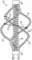
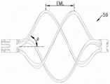
对于一些应用,制造叶轮,其方式为:形成结构,该结构在结构的近端和远端处具有第一衬套和第二衬套,第一衬套和第二衬套通过至少一个长形元件彼此连接。至少部分地通过轴向压缩该结构,使至少一个长形元件径向扩展并且形成至少一个螺旋形长形元件。将弹性体材料联接到至少一个螺旋形长形元件,使得联接有弹性体材料的至少一个螺旋形长形元件限定叶轮的叶片。典型地,执行联接,使得材料层围绕至少一个螺旋形长形元件的径向外边缘设置,材料层形成叶轮的叶片的有效边缘(即,叶轮的血液泵送功能基本上不再有效的边缘)。更典型地,该方法包括执行以下步骤,即以不导致从叶轮的叶片的有效边缘突出的方式,增强弹性体材料与至少一个螺旋形长形元件结合。例如,可以将缝合线放置在由至少一个螺旋形长形元件限定的凹槽内,使得缝合线不从螺旋形长形元件的径向外边缘突出,缝合线被配置成增强弹性体材料与至少一个螺旋形长形元件的结合。可替代地或附加地,围绕至少一个螺旋形长形元件放置紧密缠绕的线圈,使得弹性体材料沿着线圈的径向外边缘形成基本上光滑的层,线圈被配置成增强弹性体材料与至少一个螺旋形长形元件的结合。进一步可替代地或附加地,围绕至少一个螺旋形长形元件放置套筒,使得弹性体材料沿着套筒的径向外边缘形成基本上光滑的层,套筒被配置成增强弹性体材料与至少一个螺旋形长形元件的结合。对于一些应用,为至少一个螺旋形长形元件提供倒圆的截面,使得弹性体材料在弹性体材料与螺旋形长形元件的界面处形成厚度基本上均匀的层。For some applications, the impeller is fabricated by forming a structure having first and second bushings at the proximal and distal ends of the structure, the first and second bushings passing through at least one elongated The elements are connected to each other. At least in part by axially compressing the structure, the at least one elongated element is radially expanded and formed into at least one helical elongated element. The elastomeric material is coupled to the at least one helical elongated element such that the at least one helical elongated element to which the elastomeric material is coupled defines blades of the impeller. Typically, the coupling is performed such that a layer of material is disposed around the radially outer edge of the at least one helical elongated element, the layer of material forming the effective edge of the vanes of the impeller (ie the edge where the blood pumping function of the impeller is substantially no longer effective) . More typically, the method includes performing the step of combining a reinforcing elastomeric material with at least one helical elongate element in a manner that does not cause protrusion from the effective edges of the blades of the impeller. For example, the suture may be placed within the groove defined by the at least one helical elongated element such that the suture does not protrude from the radially outer edge of the helical elongated element, the suture being configured to reinforce the elastomeric material with at least one of the helical elongated elements. A combination of helical elongated elements. Alternatively or additionally, a tightly wound coil is placed around the at least one helical elongated element such that the elastomeric material forms a substantially smooth layer along the radially outer edge of the coil, the coil being configured to reinforce the elastomeric material with at least one of the coils. A combination of helical elongated elements. Further alternatively or additionally, a sleeve is placed around the at least one helical elongated element such that the elastomeric material forms a substantially smooth layer along a radially outer edge of the sleeve, the sleeve being configured to reinforce the elastomeric material with the An association of at least one helical elongated element. For some applications, at least one helical elongated element is provided with a rounded cross-section such that the elastomeric material forms a layer of substantially uniform thickness at the interface of the elastomeric material and the helical elongated element.
一般而言,在本申请的说明书和权利要求书中,当相对于装置或其一部分使用时,术语“近侧”和相关术语应被解释为当装置或其一部分被插入受试者体内时,装置或其一部分的端部通常更靠近装置通过其被插入受试者体内的位置。当相对于装置或其一部分使用时,术语“远侧”和相关术语应被解释为当装置或其一部分被插入受试者体内时,装置或其一部分的端部通常更远离装置通过其被插入受试者体内的位置。Generally, in the specification and claims of this application, when used in relation to a device or a portion thereof, the term "proximal" and related terms should be construed to mean that when the device or a portion thereof is inserted into a subject, The end of the device or a portion thereof is generally closer to the location through which the device is inserted into the subject. When used in relation to a device or a portion thereof, the term "distal" and related terms should be construed to mean that when the device or portion thereof is inserted into a subject, the end of the device or portion thereof is generally further away from the device through which the device is inserted location within the subject's body.
本发明的范围包括在除左心室和主动脉之外的解剖位置使用本文所描述的器械和方法。因此,心室辅助装置和/或其部分有时在本文中(在说明书和权利要求书中)被称为血泵。The scope of the present invention includes the use of the devices and methods described herein at anatomical locations other than the left ventricle and aorta. Accordingly, a ventricular assist device and/or a portion thereof is sometimes referred to herein (in the specification and claims) as a blood pump.
因此,根据本发明的一些应用,提供一种器械,包括:Accordingly, according to some applications of the present invention, there is provided an apparatus comprising:
左心室辅助装置,其被配置为辅助受试者的左心室功能,该左心室辅助装置包括:A left ventricular assist device configured to assist left ventricular function in a subject, the left ventricular assist device comprising:
管,其被配置成使得管的近侧部分穿过受试者的主动脉瓣,并且管的远侧部分被设置在受试者的左心室内;a tube configured such that a proximal portion of the tube passes through the aortic valve of the subject, and the distal portion of the tube is positioned within the left ventricle of the subject;
框架,其被设置在管的至少远侧部分内;a frame disposed within at least the distal portion of the tube;
泵,其被设置在框架内,并且被配置为通过管将血液从受试者的左心室泵送到受试者的主动脉,其方式为经由至少一个血液入口开口将血液泵送到管中,该血液入口开口由管限定并且被配置为设置在受试者的左心室内,并且经由至少一个血液出口开口将血液从管中泵出,该血液出口开口由管限定并且被配置为设置在受试者的主动脉内;和a pump disposed within the frame and configured to pump blood from the left ventricle of the subject through the tube to the aorta of the subject by pumping the blood into the tube via the at least one blood inlet opening , the blood inlet opening is defined by a tube and configured to be positioned within the left ventricle of the subject, and blood is pumped out of the tube via at least one blood outlet opening defined by the tube and configured to be positioned within within the subject's aorta; and
远侧尖端元件,其被配置成限定平直的近侧部分和弯曲的远侧部分,该平直的近侧部分限定纵向轴线,该弯曲的远侧部分被成形为在经过拐点并且相对于平直的近侧部分的纵向轴线在第二方向上弯曲之前相对于平直的近侧部分的纵向轴线在第一方向上弯曲,使得弯曲的远侧部分在平直的近侧部分的纵向轴线的一侧上限定隆起部。A distal tip element configured to define a straight proximal portion and a curved distal portion, the straight proximal portion defining a longitudinal axis, the curved distal portion being shaped to pass through an inflection point and relative to the flat The longitudinal axis of the straight proximal portion is curved in the first direction relative to the longitudinal axis of the straight proximal portion prior to being curved in the second direction such that the curved distal portion is in the direction of the longitudinal axis of the straight proximal portion A raised portion is defined on one side.
对于一些应用,远侧尖端元件被配置为当远侧尖端元件抵靠受试者的左心室的顶点放置时,将至少一个血液入口开口与受试者的左心室的后壁分隔开。For some applications, the distal tip element is configured to separate the at least one blood inlet opening from the posterior wall of the left ventricle of the subject when the distal tip element is placed against the apex of the left ventricle of the subject.
对于一些应用,远侧尖端元件具有问号形状。对于一些应用,远侧尖端元件具有网球拍形状。For some applications, the distal tip element has a question mark shape. For some applications, the distal tip element has the shape of a tennis racket.
对于一些应用,远侧尖端元件的弯曲的远侧部分被成形为使得在经过拐点之后,弯曲的远侧部分继续弯曲,使得弯曲的远侧部分向回交叉(cross back)到由平直的近侧部分限定的纵向轴线上。对于一些应用,远侧尖端元件的弯曲的远侧部分被成形为使得在经过拐点之后,弯曲的远侧部分不会向回交叉到由平直的近侧部分限定的纵向轴线上。For some applications, the curved distal portion of the distal tip element is shaped such that after passing the point of inflection, the curved distal portion continues to curve such that the curved distal portion crosses back to a distance from the straight proximal portion on the longitudinal axis defined by the side portion. For some applications, the curved distal portion of the distal tip element is shaped such that after passing the inflection point, the curved distal portion does not cross back onto the longitudinal axis defined by the flat proximal portion.
对于一些应用,血泵包括被设置在轴向轴杆上的叶轮,并且远侧尖端元件包括被配置成接收血泵的轴向轴杆的轴向轴杆接收管,以及被配置成限定远侧尖端元件的弯曲的远侧部分的远侧尖端部分。For some applications, the blood pump includes an impeller disposed on an axial shaft, and the distal tip element includes an axial shaft receiving tube configured to receive the axial shaft of the blood pump, and configured to define a distal end The distal tip portion of the curved distal portion of the tip element.
对于一些应用,远侧尖端元件被配置为当远侧尖端元件接触受试者的左心室的顶点时,将至少一个血液入口开口与受试者的左心室的隔膜壁分隔开。对于一些应用,远侧尖端元件被配置成使得当远侧尖端元件被插入左心室使得隆起部朝向隔膜壁隆起时,则响应于远侧尖端元件被推靠在受试者的左心室的顶点上,血液入口开口被推离隔膜壁并且被推向受试者的左心室的自由壁。对于一些应用,远侧尖端元件被配置成使得响应于远侧尖端元件被推靠在受试者的左心室的顶点上,通过远侧尖端元件的平直的近侧部分绕远侧尖端元件的弯曲的远侧部分枢转,血液入口开口被推离隔膜壁并且被推向受试者的左心室的自由壁。For some applications, the distal tip element is configured to separate the at least one blood inlet opening from the septal wall of the subject's left ventricle when the distal tip element contacts the apex of the subject's left ventricle. For some applications, the distal tip element is configured such that when the distal tip element is inserted into the left ventricle such that the bulge bulges toward the septal wall, then in response to the distal tip element being pushed against the apex of the left ventricle of the subject , the blood inlet opening is pushed away from the septal wall and toward the free wall of the subject's left ventricle. For some applications, the distal tip element is configured such that in response to the distal tip element being pushed against the apex of the left ventricle of the subject, there is a curvature about the distal tip element by a flat proximal portion of the distal tip element The distal portion of the pivoting, the blood inlet opening is pushed away from the septal wall and toward the free wall of the subject's left ventricle.
对于一些应用,远侧尖端元件被配置成使得当部署在受试者的降主动脉内时,远侧尖端元件本身相对于受试者的主动脉瓣居中。对于一些应用,弯曲的远侧部分被成形为在沿第一方向弯曲之后,在弯曲的远侧部分在沿第二方向弯曲之前,限定长形的平直部分,使得长形的平直部分相对于远侧尖端元件的近侧的平直部分的纵向轴线成一定角度突出。For some applications, the distal tip element is configured such that when deployed within the subject's descending aorta, the distal tip element itself is centered relative to the subject's aortic valve. For some applications, the curved distal portion is shaped to define an elongated straight portion after the curved distal portion is curved in the first direction and before the curved distal portion is curved in the second direction such that the elongated straight portion is opposite The longitudinal axis of the proximal flat portion of the distal tip element projects at an angle.
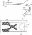
对于一些应用,鸭嘴阀被设置在远侧尖端元件的最远侧10mm内。对于一些应用,鸭嘴阀限定宽入口和窄尖端,该窄尖端限定穿过其中的缝隙,鸭嘴阀面向近侧,使得宽入口面向远侧尖端元件的远端,并且使得窄尖端背离远侧尖端元件的远端。For some applications, the duckbill valve is positioned within the most distal 10 mm of the distal tip element. For some applications, the duckbill valve defines a wide inlet and a narrow tip defining a slit therethrough, the duckbill valve faces proximally such that the wide inlet faces the distal end of the distal tip element and the narrow tip faces away distally the distal end of the tip element.
对于一些应用:For some applications:
左心室辅助装置被配置成与导引线一起使用;a left ventricular assist device configured for use with a guide wire;
远侧尖端元件限定导引线内腔;并且the distal tip element defines a guide wire lumen; and
左心室辅助装置还包括导引线引导件,该导引线引导件被设置在导引线内腔内近侧于鸭嘴阀的位置处,导引线引导件被成形为限定穿过其中的孔,该孔的直径从导引线引导件的近端到导引线引导件的远端变窄,导引线引导件的形状被配置成当导引线从左心室辅助装置的近端插入时,朝向鸭嘴阀的窄近端处的缝隙引导导引线的尖端。The left ventricular assist device also includes a guidewire guide disposed within the guidewire lumen at a location proximal to the duckbill valve, the guidewire guide being shaped to define a guidewire guide therethrough. a hole having a diameter that narrows from the proximal end of the guidewire guide to the distal end of the guidewire guide, the guidewire guide being shaped so that when the guidewire is inserted from the proximal end of the left ventricular assist device , guide the tip of the guide wire towards the slit at the narrow proximal end of the duckbill valve.
对于一些应用,鸭嘴阀被成形为在其近端处限定会聚导引部分,该会聚导引部分朝向缝隙会聚,使得导引部分被配置成进一步朝向缝隙引导导引线的尖端。For some applications, the duckbill valve is shaped to define a converging guide portion at its proximal end that converges toward the slit, such that the guide portion is configured to guide the tip of the guide wire further toward the slit.
根据本发明的一些应用,还提供一种器械,该器械包括:According to some applications of the present invention, there is also provided a device comprising:
血泵,其被配置为放置在受试者体内,该血泵包括:A blood pump configured to be placed in a subject, the blood pump comprising:
叶轮;impeller;
框架,其被配置成围绕叶轮设置;a frame configured to surround the impeller;
远侧尖端部分,其相对于框架设置在远侧;和a distal tip portion disposed distally relative to the frame; and
鸭嘴阀,其被完全设置在远侧尖端部分的最远侧10mm内,The duckbill valve, which is fully set within the most distal 10mm of the distal tip portion,
该鸭嘴阀限定宽入口和窄尖端,该窄尖端限定穿过其中的缝隙,The duckbill valve defines a wide inlet and a narrow tip defining a slit therethrough,
该鸭嘴阀面向近侧,使得宽入口面向远侧尖端部分的远端,并且使得窄尖端背离远侧尖端部分的远端。The duckbill valve faces proximally with the wide inlet facing the distal end of the distal tip portion and with the narrow tip facing away from the distal end of the distal tip portion.
根据本发明的一些应用,还提供一种与导引线一起使用的器械,该器械包括:According to some applications of the present invention, there is also provided an instrument for use with a guide wire, the instrument comprising:
经皮医疗装置,其限定从该装置的近端延伸到该装置的远端的导引线内腔;a percutaneous medical device defining a guidewire lumen extending from a proximal end of the device to a distal end of the device;
鸭嘴阀,其被设置在导引线内腔的远侧部分内,a duckbill valve disposed within the distal portion of the guide wire lumen,
该鸭嘴阀限定宽入口和窄尖端,该窄尖端限定穿过其中的缝隙,The duckbill valve defines a wide inlet and a narrow tip defining a slit therethrough,
该鸭嘴阀面向近侧,使得宽入口面向导引线内腔的远端,并且使得窄尖端背离导引线内腔的远端;和the duckbill valve faces proximally such that the wide inlet faces the distal end of the guide wire lumen and the narrow tip faces away from the distal end of the guide wire lumen; and
导引线引导件,其被设置在导引线内腔内近侧于鸭嘴阀的位置处,导引线引导件被成形为限定穿过其中的孔,该孔的直径从导引线引导件的近端到导引线引导件的远端变窄,导引线引导件的形状被配置为当导引线从经皮医疗装置的近端插入时,朝向鸭嘴阀的窄近端处的缝隙引导导引线的尖端。A guidewire guide disposed within the guidewire lumen at a location proximal to the duckbill valve, the guidewire guide being shaped to define a bore therethrough the diameter of the bore leading from the guidewire The proximal end of the piece narrows to the distal end of the guidewire guide, the guidewire guide being shaped to be positioned toward the narrow proximal end of the duckbill valve when the guidewire is inserted from the proximal end of the percutaneous medical device The slit guides the tip of the guide wire.
对于一些应用,鸭嘴阀被成形为在其近端处限定会聚导引部分,该会聚导引部分朝向缝隙会聚,使得导引部分被配置成进一步朝向缝隙引导导引线的尖端。For some applications, the duckbill valve is shaped to define a converging guide portion at its proximal end that converges toward the slit, such that the guide portion is configured to guide the tip of the guide wire further toward the slit.
根据本发明的一些应用,还提供一种器械,该器械包括:According to some applications of the present invention, there is also provided a device comprising:
左心室辅助装置,其被配置为辅助受试者的左心室功能,该左心室辅助装置包括:A left ventricular assist device configured to assist left ventricular function in a subject, the left ventricular assist device comprising:
管,其被配置为穿过受试者的主动脉瓣,使得该管的近端被设置在受试者的主动脉内,并且该管的远端被设置在受试者的左心室内;a tube configured to pass through the subject's aortic valve such that the proximal end of the tube is positioned within the subject's aorta and the distal end of the tube is positioned within the subject's left ventricle;
框架,其被设置在管的至少一部分内,该框架限定多个单元格,该框架被配置成使得在框架的非径向约束构型中,该框架包括大致柱形部分,柱形部分内的每个单元格围绕柱形部分的圆周测量的宽度小于2mm;a frame disposed within at least a portion of the tube, the frame defining a plurality of cells, the frame being configured such that in the non-radially constrained configuration of the frame, the frame includes a substantially cylindrical portion within which the The width of each cell measured around the circumference of the cylindrical portion is less than 2mm;
内衬,其衬在框架的柱形部分的至少一部分上;和an inner liner that lines at least a portion of the cylindrical portion of the frame; and
叶轮,其被设置在框架内,使得在叶轮的非径向约束构型中,在叶轮跨度最大的位置处,叶轮被设置在框架的柱形部分内,使得叶轮的外边缘与内衬之间的间隙小于1mm,The impeller is positioned within the frame such that in the non-radially constrained configuration of the impeller, at the position where the impeller span is greatest, the impeller is positioned within the cylindrical portion of the frame such that between the outer edge of the impeller and the liner The gap is less than 1mm,
叶轮被配置成:The impeller is configured to:
旋转,以便将血液从左心室泵送到主动脉,以及rotation to pump blood from the left ventricle to the aorta, and
相对于框架稳定,使得在叶轮旋转期间,叶轮的外边缘与内衬之间的间隙得以保持并且基本上恒定。Stable relative to the frame such that the clearance between the outer edge of the impeller and the liner is maintained and substantially constant during rotation of the impeller.
对于一些应用,与叶轮相对于框架不稳定的情况相比,叶轮被配置为通过相对于框架稳定来降低溶血的风险。For some applications, the impeller is configured to reduce the risk of hemolysis by being stable relative to the frame, as compared to a situation where the impeller is unstable relative to the frame.
对于一些应用,柱形部分内的每个单元格围绕柱形部分的圆周测量的宽度介于1.4mm与1.6mm之间。For some applications, each cell within the cylindrical portion has a width between 1.4 mm and 1.6 mm measured around the circumference of the cylindrical portion.
对于一些应用,柱形部分内的每个单元格围绕柱形部分的圆周测量的宽度介于1.6mm与1.8mm之间。For some applications, each cell within the cylindrical portion has a width between 1.6 mm and 1.8 mm measured around the circumference of the cylindrical portion.
对于一些应用,叶轮被配置成使得叶轮的外边缘与内衬之间的间隙小于0.4mm。For some applications, the impeller is configured such that the gap between the outer edge of the impeller and the inner liner is less than 0.4 mm.
对于一些应用:For some applications:
左心室辅助装置还包括轴向轴杆和分别设置在框架的近端和远端处的近侧径向支承件和远侧径向支承件,轴向轴杆穿过近侧径向支承件和远侧径向支承件;The left ventricular assist device also includes an axial shaft passing through the proximal radial support and a proximal radial support and a distal radial support disposed at the proximal and distal ends of the frame, respectively. a distal radial bearing;
叶轮联接到轴向轴杆;并且The impeller is coupled to the axial shaft; and
通过将叶轮相对于轴向轴杆保持在径向固定位置并且轴向轴杆是刚性的而使叶轮相对于框架得以稳定。The impeller is stabilized relative to the frame by maintaining the impeller in a radially fixed position relative to the axial shaft and the axial shaft being rigid.
对于一些应用,叶轮包括围绕轴向轴杆设置的衬套,这些衬套中的至少一个衬套被配置为相对于轴向轴杆是可滑动的,并且叶轮通过沿着轴向轴杆的以下区域相对于框架得以稳定,在该区域上,至少一个衬套被配置为相对于轴向轴杆是可滑动的,该区域被涂覆以通过减小至少一个衬套与轴向轴杆之间的间隙来基本上防止叶轮振动。For some applications, the impeller includes bushings disposed around the axial shaft, at least one of the bushings is configured to be slidable relative to the axial shaft, and the impeller passes along the axial shaft below The region is stabilized relative to the frame, on which the at least one bushing is configured to be slidable relative to the axial shaft, the region is coated to reduce the distance between the at least one bushing and the axial shaft clearance to substantially prevent impeller vibration.
对于一些应用,叶轮相对于框架得以稳定,其方式是通过框架的柱形部分的长度与框架的总长度之比大于1∶2来基本上防止框架相对于轴向轴杆的振动。For some applications, the impeller is stabilized relative to the frame by substantially preventing vibration of the frame relative to the axial shaft by the ratio of the length of the cylindrical portion of the frame to the overall length of the frame being greater than 1:2.
对于一些应用,框架的柱形部分的长度与框架的总长度之比大于2∶3。For some applications, the ratio of the length of the cylindrical portion of the frame to the overall length of the frame is greater than 2:3.
根据本发明的一些应用,还提供一种器械,该器械包括:According to some applications of the present invention, there is also provided a device comprising:
左心室辅助装置,其被配置为辅助受试者的左心室功能,该左心室辅助装置包括:A left ventricular assist device configured to assist left ventricular function in a subject, the left ventricular assist device comprising:
管,其被配置为穿过受试者的主动脉瓣,使得该管的近端被设置在受试者的主动脉内,并且该管的远端被设置在受试者的左心室内;a tube configured to pass through the subject's aortic valve such that the proximal end of the tube is positioned within the subject's aorta and the distal end of the tube is positioned within the subject's left ventricle;
框架,其被设置在管的至少一部分内,该框架限定多个单元格,该框架被配置成使得在框架的非径向约束构型中,该框架包括大致柱形部分;a frame disposed within at least a portion of the tube, the frame defining a plurality of cells, the frame configured such that in the non-radially constrained configuration of the frame, the frame includes a substantially cylindrical portion;
近侧径向支承件和远侧径向支承件,其分别被设置在框架的近端和远端处;a proximal radial bearing and a distal radial bearing disposed at the proximal and distal ends of the frame, respectively;
轴向轴杆,其穿过近侧径向支承件和远侧径向支承件;an axial shaft passing through the proximal radial bearing and the distal radial bearing;
内衬,其衬在框架的柱形部分的至少一部分上;和an inner liner that lines at least a portion of the cylindrical portion of the frame; and
叶轮,其在框架内被联接到轴向轴杆,使得在叶轮的非径向约束构型中,在叶轮跨度最大的位置处,叶轮被设置在框架的柱形部分内,使得叶轮的外边缘与内衬之间的间隙小于1mm,The impeller, which is coupled to the axial shaft within the frame, is such that in the non-radially constrained configuration of the impeller, at the position where the impeller span is greatest, the impeller is positioned within the cylindrical portion of the frame such that the outer edge of the impeller is The gap between the inner lining is less than 1mm,
该叶轮包括围绕该轴向轴杆设置的衬套,这些衬套中的至少一个衬套被配置成相对于轴向轴杆是可滑动的,并且The impeller includes a bushing disposed about the axial shaft, at least one of the bushings is configured to be slidable relative to the axial shaft, and
该叶轮通过沿着轴向轴杆的以下区域相对于框架得以稳定,在该区域上,至少一个衬套被配置成相对于轴向轴杆是可滑动的,该区域被涂覆以通过减小至少一个衬套与叶轮之间的间隙来基本上防止叶轮振动。The impeller is stabilized relative to the frame by an area along the axial shaft on which at least one bushing is configured to be slidable relative to the axial shaft, the area being coated to reduce The clearance between the at least one bushing and the impeller substantially prevents the impeller from vibrating.
对于一些应用,在沿着轴向轴杆的区域上,至少一个衬套被配置为相对于轴向轴杆是可滑动的,该区域被涂覆有类金刚石碳涂层。对于一些应用,在沿着轴向轴杆的区域上,至少一个衬套被配置为相对于轴向轴杆是可滑动的,该区域被涂覆有聚四氟乙烯涂层。对于一些应用,在沿着轴向轴杆的区域上,至少一个衬套被配置为相对于轴向轴杆是可滑动的,该区域被涂覆有聚合物套筒。对于一些应用,与叶轮相对于框架不稳定的情况相比,叶轮被配置为通过相对于框架得以稳定来降低溶血的风险。For some applications, at least one bushing is configured to be slidable relative to the axial shaft on an area along the axial shaft, the area being coated with a diamond-like carbon coating. For some applications, at least one bushing is configured to be slidable relative to the axial shaft on an area along the axial shaft, the area being coated with a Teflon coating. For some applications, at least one bushing is configured to be slidable relative to the axial shaft on an area along the axial shaft, the area being coated with a polymer sleeve. For some applications, the impeller is configured to reduce the risk of hemolysis by being stabilized relative to the frame as compared to a situation where the impeller is unstable relative to the frame.
根据本发明的一些应用,还提供一种器械,该器械包括:According to some applications of the present invention, there is also provided a device comprising:
左心室辅助装置,其被配置为辅助受试者的左心室功能,该左心室辅助装置包括:A left ventricular assist device configured to assist left ventricular function in a subject, the left ventricular assist device comprising:
管,其被配置为穿过受试者的主动脉瓣,使得该管的近端被设置在受试者的主动脉内,并且该管的远端被设置在受试者的左心室内;a tube configured to pass through the subject's aortic valve such that the proximal end of the tube is positioned within the subject's aorta and the distal end of the tube is positioned within the subject's left ventricle;
框架,其被设置在管的至少一部分内,该框架限定多个单元格,该框架被配置成使得在框架的非径向约束构型中,该框架包括大致柱形部分;a frame disposed within at least a portion of the tube, the frame defining a plurality of cells, the frame configured such that in the non-radially constrained configuration of the frame, the frame includes a substantially cylindrical portion;
近侧径向支承件和远侧径向支承件,其分别被设置在框架的近端和远端处;a proximal radial bearing and a distal radial bearing disposed at the proximal and distal ends of the frame, respectively;
轴向轴杆,其穿过近侧径向支承件和远侧径向支承件;an axial shaft passing through the proximal radial bearing and the distal radial bearing;
内衬,其衬在框架的柱形部分的至少一部分上;和an inner liner that lines at least a portion of the cylindrical portion of the frame; and
叶轮,其在框架内被联接到轴向轴杆,使得在叶轮的非径向约束构型中,在叶轮跨度最大的位置处,叶轮被设置在框架的柱形部分内,使得叶轮的外边缘与内衬之间的间隙小于1mm,The impeller, which is coupled to the axial shaft within the frame, is such that in the non-radially constrained configuration of the impeller, at the position where the impeller span is greatest, the impeller is positioned within the cylindrical portion of the frame such that the outer edge of the impeller is The gap between the inner lining is less than 1mm,
叶轮相对于框架得以稳定,其方式为通过框架的柱形部分的长度与框架的总长度之比大于1∶2来基本上防止框架相对于轴向轴杆的振动。The impeller is stabilized relative to the frame in such a way that vibrations of the frame relative to the axial shaft are substantially prevented by the ratio of the length of the cylindrical portion of the frame to the overall length of the frame being greater than 1:2.
对于一些应用,框架的柱形部分的长度与框架的总长度之比大于2∶3。For some applications, the ratio of the length of the cylindrical portion of the frame to the overall length of the frame is greater than 2:3.
对于一些应用,与叶轮相对于框架不稳定的情况相比,叶轮被配置为通过相对于框架得以稳定来降低溶血的风险。For some applications, the impeller is configured to reduce the risk of hemolysis by being stabilized relative to the frame as compared to a situation where the impeller is unstable relative to the frame.
根据本发明的一些应用,还提供一种方法,该方法包括:According to some applications of the present invention, a method is also provided, the method comprising:
制造叶轮,其方式为:The impeller is manufactured by:
形成结构,该结构在结构的近端和远端处具有第一衬套和第二衬套,该第一衬套和该第二衬套通过至少一个长形元件彼此连接;forming a structure having first and second bushings at proximal and distal ends of the structure, the first and second bushings being connected to each other by at least one elongated element;
至少部分地通过轴向压缩该结构,使该至少一个长形元件径向扩展并且形成至少一个螺旋形长形元件;并且radially expand the at least one elongated element and form at least one helical elongated element at least in part by axially compressing the structure; and
将弹性体材料联接到至少一个螺旋形长形元件,使得联接有弹性体材料的至少一个螺旋形长形元件限定叶轮的叶片,执行联接使得材料层围绕至少一个螺旋形长形元件的径向外边缘设置,该材料层形成叶轮的叶片的有效边缘;coupling the elastomeric material to the at least one helical elongated element such that the at least one helical elongated element to which the elastomeric material is coupled defines a blade of the impeller, performing the coupling such that the layer of material surrounds the radially outer portion of the at least one helical elongated element an edge arrangement, the layer of material forming the effective edge of the blades of the impeller;
该方法包括执行以不会导致从叶轮的叶片的有效边缘突出的方式来增强弹性体材料与至少一个螺旋形长形元件结合的步骤。The method includes performing the step of reinforcing the elastomeric material in combination with the at least one helical elongated element in a manner that does not cause protrusion from the effective edges of the blades of the impeller.
对于一些应用,制造叶轮还包括:将弹簧放置在该结构内,使得弹簧从第一衬套延伸到第二衬套;并且将弹性体材料联接到至少一个螺旋形长形元件包括:形成从至少一个螺旋形长形元件延伸到弹簧的弹性体材料的膜。For some applications, manufacturing the impeller further includes: placing a spring within the structure such that the spring extends from the first bushing to the second bushing; and coupling the elastomeric material to the at least one helical elongated element includes forming a A helical elongated element extends to the spring's membrane of elastomeric material.
对于一些应用:For some applications:
形成该结构包括:形成在结构的近端和远端处具有第一衬套和第二衬套的结构,这些端部部分通过两个长形元件彼此连接;forming the structure includes forming a structure having a first bushing and a second bushing at proximal and distal ends of the structure, the end portions being connected to each other by two elongated members;
使至少一个长形元件径向扩展并且形成至少一个螺旋形长形元件包括:使两个长形元件径向扩展并且形成两个螺旋形长形元件;并且Radially expanding the at least one elongated element and forming the at least one helical elongated element comprises: radially expanding the two elongated elements and forming the two helical elongated elements; and
将弹性体材料联接到至少一个螺旋形长形元件包括:将弹性体材料联接到两个螺旋形长形元件,使得联接有弹性体材料的两个螺旋形长形元件限定叶轮的叶片。Coupling the elastomeric material to the at least one helical elongated element includes coupling the elastomeric material to the two helical elongated elements such that the two helical elongated elements coupled with the elastomeric material define blades of the impeller.
对于一些应用:For some applications:
形成该结构包括:形成在结构的近端和远端处具有第一衬套和第二衬套的结构,这些端部部分通过三个或更多个长形元件彼此连接;forming the structure includes forming a structure having a first bushing and a second bushing at proximal and distal ends of the structure, the end portions being connected to each other by three or more elongated elements;
使至少一个长形元件径向扩展并且形成至少一个螺旋形长形元件包括:使三个长形元件径向扩展并且形成三个或更多个螺旋形长形元件;并且Radially expanding at least one elongated element and forming at least one helical elongated element comprises: radially expanding three elongated elements and forming three or more helical elongated elements; and
将弹性体材料联接到至少一个螺旋形长形元件包括:将弹性体材料联接到三个或更多个螺旋形长形元件,使得联接有弹性体材料的三个或更多个螺旋形长形元件中的每个螺旋形长形元件限定叶轮的相应叶片。Coupling the elastomeric material to the at least one helical elongated element includes coupling the elastomeric material to three or more helical elongated elements such that three or more helical elongated elements of the elastomeric material are coupled Each of the helical elongated elements defines a corresponding blade of the impeller.
对于一些应用,使至少一个长形元件径向扩展并且形成至少一个螺旋形长形元件还包括:扭转该结构。For some applications, radially expanding the at least one elongated element and forming the at least one helical elongated element further includes twisting the structure.
对于一些应用,执行增强弹性体材料与至少一个螺旋形长形元件结合的步骤包括:将缝合线放置在由至少一个螺旋形长形元件限定的凹槽内,使得缝合线不从螺旋形长形元件的径向外边缘突出,缝合线被配置成增强弹性体材料与至少一个螺旋形长形元件的结合。For some applications, performing the step of combining the reinforced elastomeric material with the at least one helical elongated element includes placing a suture within a groove defined by the at least one helical elongated element such that the suture does not exit the helical elongated element The radially outer edge of the element protrudes and the suture is configured to enhance the bonding of the elastomeric material to the at least one helical elongate element.
对于一些应用,执行增强弹性体材料与至少一个螺旋形长形元件结合的步骤包括:围绕至少一个螺旋形长形元件放置紧密缠绕的线圈,使得弹性体材料沿着线圈的径向外边缘形成基本上光滑的层,线圈被配置为增强弹性体材料与至少一个螺旋形长形元件的结合。For some applications, performing the step of reinforcing the elastomeric material in combination with the at least one helical elongated element includes placing a tightly wound coil around the at least one helical elongated element such that the elastomeric material forms a substantial On the smooth layer, the coil is configured to enhance the bonding of the elastomeric material with the at least one helical elongated element.
对于一些应用,执行增强弹性体材料与至少一个螺旋形长形元件结合的步骤包括:围绕至少一个螺旋形长形元件放置套筒,使得弹性体材料沿着套筒的径向外边缘形成基本上光滑的层,套筒被配置成增强弹性体材料与至少一个螺旋形长形元件的结合。For some applications, performing the step of reinforcing the elastomeric material in combination with the at least one helical elongated element includes placing a sleeve around the at least one helical elongated element such that the elastomeric material forms substantially along a radially outer edge of the sleeve The smooth layer, the sleeve is configured to enhance the bonding of the elastomeric material with the at least one helical elongated element.
对于一些应用,执行增强弹性体材料与至少一个螺旋形长形元件结合的步骤包括:为至少一个螺旋形长形元件提供倒圆的截面,使得弹性体材料在弹性体材料与螺旋形长形元件之间的界面处形成厚度基本上均匀的层。For some applications, performing the step of reinforcing the elastomeric material in combination with the at least one helical elongated element includes providing the at least one helical elongated element with a rounded cross-section such that the elastomeric material binds the helical elongated element between the elastomeric material and the helical elongated element. A layer of substantially uniform thickness is formed at the interface therebetween.
根据本发明的一些应用,还提供一种与递送导管一起使用的器械,该器械包括:According to some applications of the present invention, there is also provided a device for use with a delivery catheter, the device comprising:
血泵,该血泵包括:A blood pump, which includes:
叶轮,其被配置为将血液泵送通过受试者的身体;An impeller configured to pump blood through the subject's body;
框架,其围绕叶轮设置,a frame, which is arranged around the impeller,
该叶轮和该框架限定非径向约束构型,在非径向约束构型中叶轮被配置成在受试者体内泵送血液,并且限定径向约束构型,在径向约束构型中叶轮和框架利用递送导管插入受试者体内和从受试者体内移除,The impeller and the frame define a non-radially constrained configuration in which the impeller is configured to pump blood within a subject, and a radially constrained configuration in which the impeller is configured to pump blood and the frame is inserted into and removed from the subject using a delivery catheter,
该框架限定支柱,这些支柱具有的结构使得当框架从框架的近端向框架的中心过渡时,支柱经过接合部,在该接合部处两个支柱以Y形形式从单个支柱分支出来;the frame defines struts having a structure such that as the frame transitions from the proximal end of the frame to the center of the frame, the struts pass through a junction where two struts branch off a single strut in a Y-shape;
框架的支柱的结构被配置,使得响应于递送导管的远端和框架被移动到相对于彼此重叠的位置,框架被配置成通过变得轴向伸长而呈现其径向约束构型,并且被配置成通过变得轴向伸长而使得叶轮呈现其径向约束构型。The struts of the frame are configured such that in response to the distal end of the delivery catheter and the frame being moved into overlapping positions relative to each other, the frame is configured to assume its radially constrained configuration by becoming axially elongated, and is The impeller is configured to assume its radially constrained configuration by becoming axially elongated.
对于一些应用,框架的支柱的结构被配置,使得响应于递送导管的远端和框架被移动到相对于彼此重叠的位置,框架被配置成通过变得轴向伸长而呈现其径向约束构型,并且被配置成通过变得轴向伸长而使得叶轮呈现其径向约束构型,其方式为从接合部分支出来的成对支柱被配置成绕接合部枢转并且彼此更靠近地移动,从而闭合。For some applications, the struts of the frame are configured such that in response to the distal end of the delivery catheter and the frame being moved into overlapping positions relative to each other, the frame is configured to assume its radially constraining configuration by becoming axially elongated and is configured to cause the impeller to assume its radially constrained configuration by becoming axially elongated in such a way that pairs of struts emanating from the junction are configured to pivot about the junction and move closer to each other , thus closing.
对于一些应用,框架在其径向非约束构型中限定近侧锥形部分、远侧锥形部分以及近侧锥形部分与远侧锥形部分之间的柱形部分。For some applications, the frame, in its radially unconstrained configuration, defines a proximal tapered portion, a distal tapered portion, and a cylindrical portion between the proximal and distal tapered portions.
对于一些应用,在框架的柱形部分内,框架的支柱密度是恒定的。For some applications, the strut density of the frame is constant within the cylindrical portion of the frame.
对于一些应用,支柱的密度从近侧锥形部分到柱形部分,以及从远侧锥形部分到柱形部分增加。For some applications, the density of struts increases from the proximal tapered portion to the cylindrical portion, and from the distal tapered portion to the cylindrical portion.
对于一些应用,在血泵的运行期间,叶轮被配置为相对于框架移动,并且叶轮的移动范围使得在血泵的至少一些运行期间,叶轮的至少一部分被设置在框架的近侧锥形部分内,并且在血泵的至少一些运行期间,叶轮的至少一部分被设置在框架的柱形部分内。For some applications, the impeller is configured to move relative to the frame during operation of the blood pump, and the range of movement of the impeller is such that during at least some operation of the blood pump, at least a portion of the impeller is disposed within the proximal tapered portion of the frame and at least a portion of the impeller is disposed within the cylindrical portion of the frame during at least some operation of the blood pump.
对于一些应用,在血泵的整个运行过程中,在叶轮跨度最大的位置处,叶轮被配置成设置在框架的柱形部分内。For some applications, the impeller is configured to be disposed within the cylindrical portion of the frame at the location where the impeller span is greatest throughout the operation of the blood pump.
对于一些应用,柱形部分内的每个单元格围绕柱形部分的圆周测量的宽度小于2mm。For some applications, each cell within the cylindrical portion has a width less than 2 mm measured around the circumference of the cylindrical portion.
对于一些应用,柱形部分内的每个单元格围绕柱形部分的圆周测量的宽度介于1.4mm与1.6mm之间。For some applications, each cell within the cylindrical portion has a width between 1.4 mm and 1.6 mm measured around the circumference of the cylindrical portion.
对于一些应用,柱形部分内的每个单元格围绕柱形部分的圆周测量的宽度介于1.6mm与1.8mm之间。For some applications, each cell within the cylindrical portion has a width between 1.6 mm and 1.8 mm measured around the circumference of the cylindrical portion.
根据本发明的一些应用,还提供一种方法,该方法包括:According to some applications of the present invention, a method is also provided, the method comprising:
通过以下步骤制造用于血泵的叶轮的壳体:The housing for the impeller of the blood pump is manufactured by the following steps:
围绕芯轴放置内衬;Place a liner around the mandrel;
围绕内衬放置框架的柱形部分,框架的柱形部分包括支柱,这些支柱限定大致柱形形状;placing a cylindrical portion of the frame around the liner, the cylindrical portion of the frame including struts defining a generally cylindrical shape;
围绕框架的至少一部分放置长形管的远侧部分,该管包括近侧部分,该近侧部分限定至少一个血液出口开口;placing a distal portion of an elongated tube around at least a portion of the frame, the tube including a proximal portion defining at least one blood outlet opening;
在远侧部分围绕该框架的至少一部分设置时,经由芯轴加热内衬、框架以及长形管的远侧部分;并且heating the liner, the frame, and the distal portion of the elongated tube via the mandrel while the distal portion is disposed around at least a portion of the frame; and
在加热内衬、框架以及长形管的远侧部分时,从长形管的远侧部分外施加压力,以使长形管的远侧部分与框架的支柱的结构相一致,并且使内衬和长形管的远侧部分与框架联接。While heating the liner, the frame, and the distal portion of the elongated tube, pressure is applied from outside the distal portion of the elongated tube to conform the distal portion of the elongated tube to the configuration of the struts of the frame and to cause the liner to and the distal portion of the elongated tube is coupled to the frame.
对于一些应用,该方法还包括:在使内衬和长形管的远侧部分联接到框架之后,使框架的远端成形以限定加宽入口。For some applications, the method further includes, after coupling the liner and the distal portion of the elongated tube to the frame, shaping the distal end of the frame to define the widened inlet.
对于一些应用,该方法还包括:在使内衬和长形管的远侧部分联接到框架之后,使框架的一部分成形以形成会聚区域,使得框架在框架内的被配置成容纳叶轮的位置附近限定变窄区。For some applications, the method further includes, after coupling the liner and the distal portion of the elongated tube to the frame, shaping a portion of the frame to form a converging region such that the frame is within the frame near a location where the impeller is configured to be received Define the narrowing area.
对于一些应用,围绕框架的至少一部分放置长形管的远侧部分包括:围绕框架的整个柱形部分放置长形管的远侧部分,使得长形管的远侧部分与整个内衬重叠。For some applications, placing the distal portion of the elongated tube around at least a portion of the frame includes placing the distal portion of the elongated tube around the entire cylindrical portion of the frame such that the distal portion of the elongated tube overlaps the entire liner.
对于一些应用:For some applications:
内衬和长形管包括由彼此不同的材料制成的内衬和长形管,并且制造内衬的材料的热成型温度高于制造长形管的材料的热成型温度,并且The inner liner and the elongated tube comprise the inner liner and the elongated tube made of different materials from each other, and the thermoforming temperature of the material from which the lining is made is higher than the thermoforming temperature of the material from which the elongated tube is made, and
加热内衬、框架以及长形管的远侧部分包括:将内衬、框架以及长形管的远侧部分加热到高于制造长形管的材料的热成型温度且低于制造内衬的材料的热成型温度的温度。Heating the liner, the frame, and the distal portion of the elongated tube includes heating the liner, the frame, and the distal portion of the elongated tube to a temperature above the thermoforming temperature of the material from which the elongated tube is made and below the material from which the liner is made The temperature of the thermoforming temperature.
对于一些应用,从长形管的远侧部分外施加压力包括:使用由硅酮制成的外管从长形管的远侧部分外施加压力。For some applications, applying pressure from outside the distal portion of the elongated tube includes applying pressure from outside the distal portion of the elongated tube using an outer tube made of silicone.
对于一些应用,从长形管的远侧部分外施加压力从而使内衬和长形管的远侧部分联接到框架包括:将内衬联接到框架的柱形部分的内表面,使得内衬形成基本上柱形的管。For some applications, applying pressure from outside the distal portion of the elongated tube to couple the liner and the distal portion of the elongated tube to the frame includes coupling the liner to the inner surface of the cylindrical portion of the frame such that the liner forms A substantially cylindrical tube.
对于一些应用,框架的柱形部分内的支柱被成形为限定单元格,并且每个单元格围绕柱形部分的圆周测量的宽度小于2mm。For some applications, the struts within the cylindrical portion of the frame are shaped to define cells, and each cell has a width less than 2 mm measured around the circumference of the cylindrical portion.
对于一些应用,围绕框架的至少一部分放置长形管的远侧部分包括:仅围绕框架的柱形部分的一部分放置长形管的远侧部分,使得长形管的远侧部分不与整个内衬重叠。For some applications, placing the distal portion of the elongated tube around at least a portion of the frame includes placing the distal portion of the elongated tube around only a portion of the cylindrical portion of the frame such that the distal portion of the elongated tube is not aligned with the entire liner overlapping.
对于一些应用,仅围绕框架的柱形部分的一部分放置长形管的远侧部分包括:防止框架的柱形部分的被长形管的远侧部分围绕放置的部分径向扩展,从而引起框架的柱形部分的被长形管的远侧部分围绕放置的部分比框架的柱形部分的不被长形管的远侧部分围绕放置的部分窄。For some applications, placing the distal portion of the elongated tube around only a portion of the cylindrical portion of the frame includes preventing radial expansion of the portion of the cylindrical portion of the frame around which the distal portion of the elongated tube is placed, thereby causing a The portion of the cylindrical portion that is placed around the distal portion of the elongated tube is narrower than the portion of the cylindrical portion of the frame that is not placed around the distal portion of the elongated tube.
根据本发明的一些应用,还提供了一种器械,该器械包括:According to some applications of the present invention, there is also provided a device comprising:
血泵,其被配置为放置在受试者体内,该血泵包括:A blood pump configured to be placed in a subject, the blood pump comprising:
叶轮;impeller;
框架,其被配置成围绕叶轮设置,该框架包括支柱;a frame configured to surround the impeller, the frame including struts;
内衬,其被设置在框架内;an inner lining, which is provided within the frame;
外部覆盖材料,其在沿着框架长度的离散联接区域处从框架外联接到内部联接材料,an outer covering material that is coupled from the outside of the frame to the inner coupling material at discrete coupling regions along the length of the frame,
沿着框架的长度,框架的支柱在联接区域处的密度小于框架的支柱在其他区域处的密度。Along the length of the frame, the stanchions of the frame have a lower density at the joining regions than the stanchions of the frame at other regions.
根据本发明的一些应用,还提供一种器械,该器械包括:According to some applications of the present invention, there is also provided a device comprising:
血泵,其被配置为放置在受试者体内,该血泵包括:A blood pump configured to be placed in a subject, the blood pump comprising:
叶轮;impeller;
框架,其被配置为围绕叶轮设置,该框架包括支柱,并且该框架的柱形部分被成形为限定柱形截面;a frame configured to be disposed about the impeller, the frame including struts, and a cylindrical portion of the frame shaped to define a cylindrical cross-section;
内衬,其被设置在框架内;an inner lining, which is provided within the frame;
外部覆盖材料,其从框架外联接到内部联接材料,外部覆盖材料仅围绕框架的柱形部分的一部分设置,并且外部覆盖材料被配置成限制框架的柱形部分的被围绕放置有外部覆盖材料的部分的径向扩展,使得框架的柱形区域的被围绕放置有外部覆盖材料的远侧部分的部分比框架的柱形区域的不被围绕放置有外部覆盖材料的部分窄。The outer covering material is externally coupled from the frame to the inner coupling material, the outer covering material is provided around only a portion of the cylindrical portion of the frame, and the outer covering material is configured to limit the cylindrical portion of the frame being placed around the outer covering material. The radial expansion of the portion is such that the portion of the cylindrical region of the frame that is surrounded by the distal portion where the outer covering material is placed is narrower than the portion of the cylindrical region of the frame that is not surrounded by the outer covering material placed.
根据本发明的一些应用,还提供一种器械,该器械包括:According to some applications of the present invention, there is also provided a device comprising:
血泵,其被配置为放置在受试者体内,该血泵包括:A blood pump configured to be placed in a subject, the blood pump comprising:
叶轮;impeller;
框架,其被配置成围绕叶轮设置,该框架被配置成限定具有基本上柱形截面的柱形部分;a frame configured to be disposed about the impeller, the frame configured to define a cylindrical portion having a substantially cylindrical cross-section;
覆盖材料,其被联接到框架的柱形部分,使得框架的柱形部分的远端限定血液入口开口,叶轮被配置成在叶轮的整个运行过程中被设置在血液入口开口的15mm内,a cover material coupled to the cylindrical portion of the frame such that the distal end of the cylindrical portion of the frame defines a blood inlet opening, the impeller configured to be positioned within 15 mm of the blood inlet opening throughout operation of the impeller,
框架的一部分被成形为减少在血液从血液入口开口流向叶轮时产生的湍流。A portion of the frame is shaped to reduce turbulence created as blood flows from the blood inlet opening to the impeller.
对于一些应用,框架的一部分包括框架的加宽部分。For some applications, a portion of the frame includes a widened portion of the frame.
对于一些应用,框架的一部分包括框架的被成形为朝向叶轮会聚的一部分。For some applications, a portion of the frame includes a portion of the frame that is shaped to converge toward the impeller.
根据结合附图进行的本发明的实施例的以下详细描述,本发明将得到更完全地理解,在附图中:The present invention will be more fully understood from the following detailed description of embodiments of the invention taken in conjunction with the accompanying drawings, in which:
附图简述Brief Description of Drawings
图1A、图1B和图1C是根据本发明的一些应用的心室辅助装置的示意图,该心室辅助装置的远端被配置成放置在受试者的左心室中;1A, 1B, and 1C are schematic illustrations of a ventricular assist device, the distal end of which is configured for placement in the left ventricle of a subject, in accordance with some applications of the present invention;
图2A、图2B、图2C、图2D、图2E和图2F是根据本发明的一些应用的容纳心室辅助装置的叶轮的框架的示意图;2A, 2B, 2C, 2D, 2E, and 2F are schematic illustrations of a frame housing an impeller of a ventricular assist device according to some applications of the present invention;
图3A、图3B、图3C、图3D、图3E、图3F、图3G、图3H、图3I、图3J和图3K是根据本发明的一些应用的心室辅助装置的叶轮或其一部分的示意图;3A, 3B, 3C, 3D, 3E, 3F, 3G, 3H, 3I, 3J, and 3K are schematic illustrations of an impeller or a portion of a ventricular assist device according to some applications of the present invention ;
图4是根据本发明的一些应用的被设置在心室辅助装置的框架内的叶轮的示意图;4 is a schematic diagram of an impeller disposed within the frame of a ventricular assist device according to some applications of the present invention;
图5A和图5B是根据本发明的一些应用的分别处于非径向约束状态和径向约束状态下的心室辅助装置的叶轮和框架的示意图;5A and 5B are schematic diagrams of an impeller and frame of a ventricular assist device in a non-radially constrained state and a radially constrained state, respectively, according to some applications of the present invention;
图5C是在现有技术的基于轴流式叶轮的血泵中使用的典型支承组件的示意图;5C is a schematic diagram of a typical support assembly used in a prior art axial-flow impeller-based blood pump;
图6A和图6B是根据本发明的一些应用的,在心室辅助装置的叶轮相对于心室辅助装置的框架处于运动周期的各个阶段的心室辅助装置的示意图;6A and 6B are schematic diagrams of a ventricular assist device with the ventricular assist device impeller at various stages of a motion cycle relative to the ventricular assist device frame, according to some applications of the present invention;
图6C是根据本发明的一些应用的心室辅助装置的远侧尖端元件的示意图,该远侧尖端元件包括轴向轴杆接收管和远侧尖端部分;6C is a schematic illustration of a distal tip element of a ventricular assist device including an axial shaft receiving tube and a distal tip portion in accordance with some applications of the present invention;
图6D是根据本发明的一些应用的心室辅助装置的轴向轴杆的示意图,该轴向轴杆至少部分被覆盖或涂覆,以减小轴向轴杆与叶轮的在轴向轴杆上滑动的衬套之间的间隙;6D is a schematic illustration of an axial shaft of a ventricular assist device that is at least partially covered or coated to reduce friction between the axial shaft and the impeller on the axial shaft, according to some applications of the present invention. the gap between the sliding bushings;
图6E是根据本发明的一些应用的心室辅助装置的轴向轴杆和叶轮的在轴向轴杆上滑动的衬套的示意图,轴向轴杆和叶轮的衬套被配置成防止叶轮的衬套相对于轴向轴杆的旋转运动;6E is a schematic illustration of an axial shaft of a ventricular assist device and a bushing of an impeller sliding on the axial shaft configured to prevent a bushing of the impeller in accordance with some applications of the present invention Rotational movement of the sleeve relative to the axial shaft;
图6F和图6G是根据本发明的一些应用的叶轮壳体的示意图,该叶轮壳体被配置为在叶轮与壳体之间提供间隙,该间隙在受试者的心动周期过程中变化;6F and 6G are schematic illustrations of an impeller housing configured to provide a gap between the impeller and the housing that varies during a subject's cardiac cycle, according to some applications of the present invention;
图7是根据本发明的一些应用的心室辅助装置的马达单元的示意图;7 is a schematic diagram of a motor unit of a ventricular assist device according to some applications of the present invention;
图8A和图8B是根据本发明的一些应用的心室辅助装置的马达单元的示意图;8A and 8B are schematic diagrams of a motor unit of a ventricular assist device according to some applications of the present invention;
图9是表示心室辅助装置的驱动线缆长度随本申请的发明人进行的实验中所测量到的血泵的叶轮所抵抗的压力梯度变化而变化的曲线图;9 is a graph showing the change in the length of the drive cable of the ventricular assist device as a function of the pressure gradient resisted by the impeller of the blood pump measured in the experiments performed by the inventors of the present application;
图10A、图10B和图10C是根据本发明的一些应用的心室辅助装置的驱动线缆的示意图;10A, 10B, and 10C are schematic diagrams of a drive cable of a ventricular assist device according to some applications of the present invention;
图10D、图10E和图10F是根据本发明的一些应用的心室辅助装置的驱动线缆和轴向轴杆的示意图;Figures 10D, 10E and 10F are schematic illustrations of a drive cable and axial shaft of a ventricular assist device according to some applications of the present invention;
图11A和图11B是根据本发明的一些应用的叶轮的示意图,该叶轮在叶轮的远端处联接到轴向轴杆,而在叶轮的近端处不联接到轴向轴杆;11A and 11B are schematic diagrams of an impeller coupled to an axial shaft at the distal end of the impeller and not coupled to the axial shaft at the proximal end of the impeller, according to some applications of the present invention;
图11C是用于促进图11A和图11B的叶轮压接的联接部分的示意图;Figure 11C is a schematic diagram of a coupling portion for facilitating crimping of the impeller of Figures 11A and 11B;
图12A是示出了当叶轮被配置成如图11A所示时叶轮泵送所抵抗的压力梯度与叶轮的节距之间的关系的曲线图;12A is a graph showing the relationship between the pressure gradient against which the impeller is pumping and the pitch of the impeller when the impeller is configured as shown in FIG. 11A;
图12B是示出了根据本发明的一些应用的具有相应节距的叶轮的压力-流量曲线的曲线图;12B is a graph showing pressure-flow curves for impellers having corresponding pitches in accordance with some applications of the present invention;
图13A、图13B和图13C是根据本发明的一些应用的用于清洗心室辅助装置的驱动线缆和/或径向支承件的过程的示意图;13A, 13B, and 13C are schematic illustrations of a process for cleaning drive cables and/or radial supports of a ventricular assist device according to some applications of the present invention;
图13D是根据本发明的一些应用的心室辅助装置的示意图,该心室辅助装置包括围绕其远侧尖端部分设置的可膨胀部分(例如,球囊),该可膨胀部分被配置成通过用于清洗该装置的驱动线缆的流体而膨胀;13D is a schematic illustration of a ventricular assist device including an inflatable portion (eg, a balloon) disposed about a distal tip portion thereof, the inflatable portion being configured to pass through for cleaning, according to some applications of the present invention. expansion of the fluid of the drive cable of the device;
图13E是根据本发明的一些应用的用于减小驱动线缆与驱动线缆在其中旋转的外管之间的摩擦力、和/或用于减小心室辅助装置的径向支承件处的摩擦力的技术的示意图;13E is for reducing friction between the drive cable and the outer tube in which the drive cable rotates, and/or for reducing the radial support of a ventricular assist device, in accordance with some applications of the present invention Schematic diagram of the friction technique;
图14A、图14B和图14C是根据本发明的一些应用的定子的示意图,该定子被配置成设置在心室辅助装置的管内,近侧于其中设置有心室辅助装置的叶轮的框架;14A, 14B, and 14C are schematic illustrations of a stator configured to be disposed within a tube of a ventricular assist device proximal to a frame of a ventricular assist device impeller disposed therein, in accordance with some applications of the present invention;
图15A、图15B、图15C、图15D和图15E是根据本发明的一些应用的内置在心室辅助装置的管中的定子的示意图;15A, 15B, 15C, 15D, and 15E are schematic illustrations of a stator built into a tube of a ventricular assist device according to some applications of the present invention;
图16A和图16B是根据本发明的一些应用的包括一个或更多个心室血压测量管的心室辅助装置的示意图;16A and 16B are schematic diagrams of a ventricular assist device including one or more ventricular blood pressure measuring tubes according to some applications of the present invention;
图16C和图16D是根据本发明的一些应用的在递送导管内具有主动脉血压测量通道的心室辅助装置的示意图;16C and 16D are schematic diagrams of a ventricular assist device having an aortic blood pressure measurement channel within a delivery catheter in accordance with some applications of the present invention;
图16E是根据本发明的一些应用的心室辅助装置的示意图,该心室辅助装置包括设置在该装置的管的外表面上的一个或更多个传感器;16E is a schematic diagram of a ventricular assist device including one or more sensors disposed on an outer surface of a tube of the device, according to some applications of the present invention;
图17A、图17B、图17C和图17D是根据本发明的一些应用的心室辅助装置的示意图,该心室辅助装置包括皮托管(pitot tube),该皮托管被配置成测量通过该装置的管的血流量;17A, 17B, 17C, and 17D are schematic diagrams of a ventricular assist device including a pitot tube configured to measure a tube passing through the device, according to some applications of the present invention. blood flow;
图18是根据本发明的一些应用的包括冠状动脉管和/或线的心室辅助装置的示意图;18 is a schematic illustration of a ventricular assist device including a coronary tube and/or wire according to some applications of the present invention;
图19A、图19B、图19C、图19D、图19E、图19F、图19G和图19H是根据本发明的一些应用的心室辅助装置的示意图,该心室辅助装置包括位于容纳叶轮的框架内侧上的内衬;19A, 19B, 19C, 19D, 19E, 19F, 19G, and 19H are schematic illustrations of a ventricular assist device including a lining;
图20A、图20B和图20C是根据本发明的一些应用的心室辅助装置的示意图,该心室辅助装置包括围绕其远侧尖端部分设置的可膨胀部分(例如,球囊);Figures 20A, 20B, and 20C are schematic illustrations of a ventricular assist device including an inflatable portion (eg, a balloon) disposed about its distal tip portion, according to some applications of the present invention;
图21是根据本发明的一些应用的被放置在受试者的左心室内的心室辅助装置的示意图,其中示出了左心室的横截面视图;21 is a schematic diagram of a ventricular assist device placed within the left ventricle of a subject, showing a cross-sectional view of the left ventricle, in accordance with some applications of the present invention;
图22A、图22B、图22C和图22D是根据本发明的一些应用的心室辅助装置的远侧尖端元件的示意图,该远侧尖端元件至少部分弯曲,从而限定问号形状或网球拍形状;22A, 22B, 22C and 22D are schematic illustrations of a distal tip element of a ventricular assist device according to some applications of the present invention, the distal tip element being at least partially curved to define a question mark shape or tennis racket shape;
图23A和图23B是根据本发明的一些应用的图22D的心室辅助装置的示意图,该心室辅助装置被设置在受试者的左心室内;Figures 23A and 23B are schematic illustrations of the ventricular assist device of Figure 22D positioned within the left ventricle of a subject in accordance with some applications of the present invention;
图24A、图24B和图24C是根据本发明的一些应用的远侧尖端元件的示意图,该远侧尖端元件被配置成使其自身相对于受试者的主动脉瓣居中;24A, 24B, and 24C are schematic illustrations of a distal tip element configured to center itself relative to a subject's aortic valve, according to some applications of the present invention;
图25A、图25B、图25C、图25D和图25E是根据本发明的一些应用的心室辅助装置的示意图,该心室辅助装置包括管,该管被配置成当血液通过管被泵送时变得弯曲;Figures 25A, 25B, 25C, 25D, and 25E are schematic illustrations of a ventricular assist device including a tube configured to become blood as blood is pumped through the tube, according to some applications of the present invention. bending;
图25F是根据本发明的一些应用的心室辅助装置的示意图,该心室辅助装置包括弯曲元件,该弯曲元件由形状记忆材料制成并且被配置为向心室辅助装置的一部分提供预定曲率;25F is a schematic diagram of a ventricular assist device including a curved element made of a shape memory material and configured to provide a predetermined curvature to a portion of the ventricular assist device, according to some applications of the present invention;
图26A、图26B、图26C、图26D、图26E和图26F是根据本发明的一些应用的心室辅助装置的至少部分弯曲的远侧尖端元件的示意图;26A, 26B, 26C, 26D, 26E, and 26F are schematic illustrations of an at least partially curved distal tip element of a ventricular assist device according to some applications of the present invention;
图27A、图27B和图27C是根据本发明的一些应用的防创伤突出部的示意图,该防创伤突出部包括闭合椭圆或闭合圆并且被配置为从心室辅助装置的远侧尖端元件向远侧延伸;27A, 27B, and 27C are schematic illustrations of atraumatic protrusions comprising a closed ellipse or closed circle and configured to extend distally from a distal tip element of a ventricular assist device in accordance with some applications of the present invention extend;
图28A是根据本发明的一些应用的被设置在防创伤尖端的远端处的鸭嘴阀和导引线引导件的示意图;28A is a schematic illustration of a duckbill valve and guidewire guide disposed at the distal end of the atraumatic tip, according to some applications of the present invention;
图28B和图28C是根据本发明的一些应用的图28A的鸭嘴阀的相应视图的示意图;28B and 28C are schematic diagrams of respective views of the duckbill valve of FIG. 28A according to some applications of the present invention;
图28D和图28E是根据本发明的一些应用的图28A的导引线引导件的相应视图的示意图;28D and 28E are schematic diagrams of respective views of the guidewire guide of FIG. 28A according to some applications of the present invention;
图29是根据本发明的一些应用的递送导管的示意图,该递送导管包括护套,该护套被配置成有助于导引线通过经皮穿刺的重新插入;29 is a schematic illustration of a delivery catheter including a sheath configured to facilitate reinsertion of a guide wire through percutaneous puncture, according to some applications of the present invention;
图30是根据本发明的一些应用的包括两个叶轮的心室辅助装置的示意图;30 is a schematic diagram of a ventricular assist device including two impellers according to some applications of the present invention;
图31是根据本发明的一些应用的包括两个叶轮的心室辅助装置的示意图;31 is a schematic diagram of a ventricular assist device including two impellers in accordance with some applications of the present invention;
图32A、图32B、图32C、图32D和图32E是根据本发明的一些应用的心室辅助装置的示意图,该心室辅助装置被配置为辅助受试者的右心的功能;以及Figures 32A, 32B, 32C, 32D, and 32E are schematic illustrations of a ventricular assist device configured to assist the function of a subject's right heart, according to some applications of the present invention; and
图33是根据本发明的一些应用的静脉辅助装置的示意图。33 is a schematic illustration of an intravenous assist device according to some applications of the present invention.
具体实施方式Detailed ways
现在参照图1A、图1B和图1C,这些图是根据本发明的一些应用的心室辅助装置20的示意图,心室辅助装置的远端被配置成设置在受试者的左心室22中。图1A示出了包括控制台21和马达单元23的心室辅助装置系统的概览,图1B示出了被插入受试者的左心室的心室辅助装置,并且图1C更详细地示出了心室辅助装置的泵部分27。心室辅助装置包括管24,该管穿过受试者的主动脉瓣26,使得管的近端28被设置在受试者的主动脉30中,而管的远端32被设置在左心室22内。典型地,管24(其在本文中有时被称为“血泵管”)是长形管,管的轴向长度典型地比其直径大得多。本发明的范围包括在除左心室和主动脉之外的解剖位置中使用本文所描述的器械和方法。因此,心室辅助装置和/或其部分有时在本文中(在说明书和权利要求书中)被称为血泵。Referring now to FIGS. 1A , 1B, and 1C, these figures are schematic illustrations of a
对于一些应用,心室辅助装置用于在经皮冠脉介入治疗期间辅助受试者的左心室的功能。在这种情况下,心室辅助装置典型地使用长达10小时(例如,长达6小时)的时间段,在此时间段期间有发展出血液动力学不稳定的风险(例如,在经皮冠脉介入治疗期间或紧接着经皮冠脉介入治疗之后)。可替代地或附加地,心室辅助装置用于在患有心源性休克的病人身上辅助受试者的左心室的功能更长时间段(举例来说,例如,2天-20天,例如,4天-14天),心源性休克可以包括任何低心输出量状态(例如,急性心肌梗塞、心肌炎、心肌病、产后等)。对于一些应用,心室辅助装置用于辅助受试者的左心室的功能更长的时间段(例如,几周或几个月),例如,在“心功能恢复(bridge to recovery)”治疗中。对于一些这样的应用,心室辅助装置是永久或半永久植入的,并且心室辅助装置的叶轮是经皮供电的,例如,使用磁耦合到叶轮的外部天线。For some applications, ventricular assist devices are used to assist the function of the left ventricle of a subject during percutaneous coronary intervention. In this case, the ventricular assist device is typically used for a period of up to 10 hours (eg, up to 6 hours) during which there is a risk of developing hemodynamic instability (eg, in percutaneous coronary interventions) during or immediately after percutaneous coronary intervention). Alternatively or additionally, a ventricular assist device is used to assist the function of the left ventricle of the subject for a longer period of time (eg, eg, 2 days to 20 days, eg, 4 days) in patients with cardiogenic shock. Day-14), cardiogenic shock can include any state of low cardiac output (eg, acute myocardial infarction, myocarditis, cardiomyopathy, postpartum, etc.). For some applications, ventricular assist devices are used to assist the function of a subject's left ventricle for longer periods of time (eg, weeks or months), eg, in "bridge to recovery" therapy. For some such applications, the ventricular assist device is permanently or semi-permanently implanted, and the ventricular assist device impeller is powered percutaneously, eg, using an external antenna magnetically coupled to the impeller.
如图1B所示,该图示出了心室辅助装置在左心室中部署的步骤,典型地,心室辅助装置的远端通过导引线10被引导至左心室。在将装置的远端插入左心室期间,递送导管143被设置在装置的远端上。一旦将装置的远端设置在左心室中,则递送导管典型地缩回到主动脉,并且将导引线从受试者身体中抽出。典型地,递送导管的缩回引起装置的远端的自扩展部件呈现非径向约束构型,如下文进一步详细描述的。典型地,心室辅助装置被插入受试者体内,以便为受试者提供急性治疗。对于一些应用,为了在治疗结束时将左心室装置从受试者体内抽出,递送导管在装置的远端上被推进,这使得装置的远端的自扩展部件呈现径向约束构型。可替代地或附加地,装置的远端缩回到递送导管中,这使得装置的远端的自扩展部件呈现径向约束构型。As shown in FIG. 1B , which shows the steps of deployment of a ventricular assist device in the left ventricle, typically the distal end of the ventricular assist device is guided to the left ventricle by a
对于一些应用(未示出),心室辅助装置和/或递送导管143在其远端处包括超声换能器,并且心室辅助装置在超声引导下朝向受试者的心室被推进。For some applications (not shown), the ventricular assist device and/or
现在参照图1C,该图更详细地示出了心室辅助装置20的泵部分27,典型地,叶轮50被设置在管24的远侧部分102内并且被配置成通过旋转将血液从左心室泵入主动脉。该管典型地在管的远端处限定一个或更多个血液入口开口108,在叶轮运行期间,血液经由血液入口开口从左心室流入到管中。对于一些应用,管的近侧部分106限定一个或更多个血液出口开口109,在叶轮运行过程中,血液经由血液出口开口从管流入升主动脉。Referring now to FIG. 1C , which shows the
对于一些应用,典型地包括计算机处理器25的控制台21(如图1A所示)驱动叶轮旋转。例如,计算机处理器可以控制马达74(如图7所示),马达74被设置在马达单元23(如图1A所示)内,并且经由驱动线缆130(如图7所示)驱动叶轮旋转。对于一些应用,计算机处理器被配置成检测受试者的生理参数(例如左心室压力、心脏后负荷、左心室压力的变化率等)并且响应于此来控制叶轮的旋转,如下文进一步详细描述的。典型地,本文描述的由计算机处理器执行的运行根据所使用的存储器技术,将存储器的物理状态转换成具有不同的磁极性、电荷等,该存储器是与计算机处理器通信的真实物理制品。计算机处理器25典型地是用计算机程序指令编程的硬件设备,以产生专用计算机。例如,当被编程来执行本文描述的技术时,计算机处理器25典型地充当专用的心室辅助计算机处理器和/或专用的血泵计算机处理器。For some applications, a console 21 (shown in FIG. 1A ), which typically includes a
对于一些应用,清洗系统29(在图1A中示出)驱动流体(例如,葡萄糖溶液)穿过心室辅助装置20的多个部分,例如,以便冷却装置的多个部分和/或以便冲刷来自装置的多个部分的碎屑。清洗系统29将在下文中进一步详细描述。For some applications, a cleaning system 29 (shown in FIG. 1A ) drives fluid (eg, a glucose solution) through portions of the ventricular assist
典型地,沿着管24的远侧部分102,框架34围绕叶轮50设置在管内。框架典型地由形状记忆合金制成,例如镍钛诺。对于一些应用,框架的形状记忆合金定形为使得在没有任何力被施加到管24的远侧部分102的情况下,框架的至少一部分(并且因此管24的远侧部分102)呈现大致圆形、椭圆形或多边形的截面形状。通过呈现框架的大致圆形、椭圆形或多边形的截面形状,框架被配置成将管的远侧部分保持在打开状态。典型地,在心室辅助装置的运行期间,管的远侧部分被配置成放置在受试者体内,使得管的远侧部分至少部分地设置在左心室内。Typically, along the
对于一些应用,沿着管24的近侧部分106,框架不设置在管内,因此管不被框架34支撑在打开状态。管24典型地由不可渗透血液的可塌缩材料制成。例如,管24可以包括聚氨酯、聚酯和/或硅酮。可替代地或附加地,管由聚对苯二甲酸乙二醇酯(PET)和/或聚醚嵌段酰胺(例如,
再次参照图1C,对于一些应用,框架34被成形为使得框架限定近侧锥形部分36、中心柱形部分38和远侧锥形部分40。典型地,近侧锥形部分是这样的,使得锥体的窄端相对于锥体的宽端是近侧的。更典型地,远侧锥形部分是这样的,使得锥体的窄端相对于锥体的宽端是远侧的。对于一些应用,管24延伸到柱形部分38的端部(或稍微在其近侧或远侧),使得管的远端限定单个面向轴向的血液入口开口108,如图1C所示。对于一些应用,在框架34的至少一部分内,内衬39衬在框架上,如下文参照图19A-图19H所述。根据相应的应用,内衬在框架的被内衬所衬的部分上与管24部分重叠或完全重叠。对于这样的应用,内衬的远端限定单个面向轴向的血液入口开口108。对于一些应用(未示出),管24延伸到远侧锥形部分40的端部,并且管限定一个或更多个侧向血液入口开口(未示出),例如,如在Tuval的US2019/0209758中所述,其通过引用并入本文。对于这样的应用,管典型地限定两个到四个侧向血液入口开口。Referring again to FIG. 1C , for some applications, the
典型地,管24包括锥形近侧部分42和柱形中心部分44。近侧锥形部分典型地是这样的,使得锥体的窄端相对于锥体的宽端是近侧的。典型地,血液出口开口109由管24限定,使得开口至少部分地沿着管24的近侧锥形节段延伸。对于一些这样的应用,血液出口开口是泪珠形的,如图1C所示。典型地,血液出口开口的泪珠形属性与至少部分地沿着管24的近侧锥形节段延伸的开口相结合,使得血液沿着与管24的纵向轴线基本上平行的流线在血液出口开口的位置处流出血液出口开口。Typically, the
如上所述,对于一些应用(未示出),管延伸到框架34的远侧锥形部分40的端部。对于这种应用,管典型地限定远侧锥形部分,其中锥体的窄端相对于锥体的宽端是远侧的。对于一些应用(未示出),管24的直径沿着管的中心部分的长度变化,使得管的中心部分具有截头锥形状。例如,管的中心部分可以从其近端向其远端变宽,或者可以从其近端向其远端变窄。对于一些应用,在其近端处,管的中心部分具有介于5mm与7mm之间的直径,而在其远端处,管的中心部分具有介于8mm与12mm之间的直径。As mentioned above, for some applications (not shown), the tube extends to the end of the distal tapered
再次参照图1C,心室辅助装置典型地包括远侧尖端元件107,该远侧尖端元件107相对于框架34设置在远侧并且包括轴向轴杆接收管126和远侧尖端部分120,这两者将在下文中进一步详细描述。Referring again to Figure 1C, a ventricular assist device typically includes a
现在参照图2A、图2B、图2C、图2D、图2E和图2F,这些图是根据本发明的一些应用的容纳心室辅助装置20的叶轮的框架34的示意图。如上文所述,框架34典型地由诸如镍钛诺的形状记忆合金制成,并且框架的形状记忆合金定形成使得框架(并且因此管24)在没有任何力被施加到管24的情况下呈现大致圆形、椭圆形或多边形的截面形状。通过呈现其大致圆形、椭圆形或多边形的截面形状,框架被配置成将管的远侧部分保持在打开状态。Reference is now made to Figures 2A, 2B, 2C, 2D, 2E, and 2F, which are schematic illustrations of a
典型地,框架是支架状框架,因为它包括依次限定单元格的支柱。更典型地,框架被管24覆盖,和/或被内衬39覆盖,如下文参照图19A-图19H所述。如下文所述,对于一些应用,叶轮50相对于框架34进行轴向往复运动。典型地,在叶轮相对于框架的运动过程中,叶轮的限定叶轮最大跨度的部分的位置被设置在框架34的柱形部分38内。在一些情况下,如果框架34的柱形部分38的单元格太大,则管24和/或内衬39在单元格的边缘之间被拉伸,使得管24和/或内衬39不限定圆形截面。对于一些应用,如果这发生在叶轮的限定叶轮最大跨度的部分所设置的区域中,则这导致在叶轮旋转周期的过程中,叶轮的叶片的边缘与该位置处的管24(和/或内衬)之间的间隙不恒定。对于一些应用,与在叶轮的旋转周期的过程中叶轮的叶片的边缘与该位置处的管24(和/或内衬)之间存在恒定的间隙的情况相比,这可能导致溶血增加。Typically, the frame is a scaffold-like frame in that it includes struts that in turn define cells. More typically, the frame is covered by the
参照图2A,至少部分地考虑到上一段中描述的问题,在框架34的柱形部分38内,框架限定大量相对小的单元格。典型地,当框架以其非径向约束构型设置时,框架的柱形部分内的每个单元格的最大单元格宽度CW(即,从支架在单元格一侧的中心接合部处的内边缘到支架在该单元格另一侧的中心接合部处的内边缘的距离,如围绕柱形部分38的圆周测量的)小于2mm,例如,介于1.4mm与1.6mm之间,或者介于1.6mm与1.8mm之间。由于单元格相对小,因此管24(和/或内衬)在框架的柱形部分内限定基本上圆形截面。Referring to Figure 2A, taking into account, at least in part, the problems described in the preceding paragraph, within the
仍然参照图2A,并且从框架的近端(在图的左侧)开始,框架典型地限定以下部分:(a)联接部分31,框架经由该联接部分联接到心室辅助装置的近侧支承件116(在图4中示出),(b)近侧锥形部分36,(c)柱形部分38,(d)远侧锥形部分40,和(e)远侧支柱接合部33。如所示的,当框架从框架的近端向框架的中心过渡时(例如,当框架通过联接部分31,通过近侧锥形部分36,并且过渡到柱形部分38时),框架的支柱37经过接合部35,在这些接合部35处,两个支柱以Y形形式从单个支柱分支出来。如下文进一步详细描述的,典型地,框架34通过框架被轴向伸长而以径向约束(即,压接)构型放置在递送导管143中。此外典型地,框架将其径向变窄传递给叶轮,并且叶轮通过在框架内轴向伸长而变得受到径向约束。对于一些应用,以上述方式配置的框架的支柱有助于将轴向伸长从递送导管(或被配置成压接框架的其他装置)传递到框架,这进而有助于将轴向伸长传递到叶轮。这是因为从每个接合部35分支出来的成对支柱被配置成绕接合部枢转,并且彼此更靠近地移动,从而闭合。Still referring to Figure 2A, and starting from the proximal end of the frame (on the left side of the figure), the frame typically defines the following: (a) a
仍然参照图2A,对于一些应用,当框架联接到轴向轴杆92(在图2D中示出)时,远侧支柱接合部33保持在打开状态,以便叶轮经由框架的远端被放置在框架内。随后,远侧支柱部分绕远侧支承件118的外侧闭合,如下面参照图5A-图5B进一步详细描述的。对于一些应用,远侧尖端元件107的近端(图1C所示)将远侧支柱部分保持在它们的围绕远侧支承件118外侧的闭合构型。Still referring to Figure 2A, for some applications, when the frame is coupled to the axial shaft 92 (shown in Figure 2D), the distal strut joints 33 remain open so that the impeller is placed on the frame via the distal end of the frame Inside. Subsequently, the distal strut portion is closed around the outside of the
典型地,当框架34以其非径向约束构型设置时,该框架34所具有的总长度大于25mm(例如,大于30mm),和/或小于50mm(例如,小于45mm),例如,25mm-50mm,或30mm-45mm。典型地,当框架以其径向约束构型设置时(在递送导管143内),该框架的长度增加了2mm至5mm之间。典型地,当框架34以其非径向约束构型设置时,该框架34的柱形部分所具有的长度大于10mm(例如大于12mm),和/或小于25mm(例如小于20mm),例如10mm-25mm,或12mm-20mm。对于一些应用,框架的柱形部分的长度与框架的总长度之比大于1∶4和/或小于1∶2,例如介于1∶4与1∶2之间。Typically, the
现在参照图2B,该图是根据本发明的一些应用的心室辅助装置20的泵部分的示意图,心室辅助装置的框架34的柱形部分38的至少一部分具有螺旋形结构55。对于一些应用,心室辅助装置的框架34的柱形部分38的至少一部分具有螺旋形结构55,以便管24(和/或内衬)在框架的柱形部分内限定基本上圆形截面,例如,由于上文提供的原因。Referring now to FIG. 2B , which is a schematic illustration of the pump portion of a
现在参照图2C,该图是框架34的示意图,框架在相对短的距离D上从其端部过渡到其最大直径(即,框架的柱形部分)。典型地,这导致框架的柱形部分与框架的总长度之比大于上述比。例如,框架的柱形部分与框架的总长度之比可以大于1∶2或大于2∶3。更典型地,这导致框架在锥形部分内变宽的角度相比于柱形部分具有较短相对长度的情况(假设其余情况均相同)变得更大。反过来,对于一些应用,这减少了叶轮旋转期间框架的振动。如上所述,为了减少溶血,典型地希望在叶轮的叶片的边缘与管24(和/或内衬39)之间保持恒定的间隙。因此,典型地希望减少框架相对于叶轮的振动。Referring now to FIG. 2C, which is a schematic illustration of
现在参照图2D,该图是根据本发明的一些应用的心室辅助装置的泵部分的示意图,该心室辅助装置包括可膨胀的叶轮壳体60。对于一些应用,不是让框架34包围叶轮,而是可膨胀的壳体包围叶轮。对于一些应用,至少在壳体的包围叶轮的区域中,框架被配置成限定内部圆形截面,使得在叶轮的旋转周期过程中,在叶轮的叶片的边缘和壳体的内壁之间存在恒定的间隙。Referring now to FIG. 2D , this figure is a schematic diagram of the pump portion of a ventricular assist device including an
典型地,对于如图2D所示的应用,近侧支承框架和远侧支承框架61被设置在可膨胀的叶轮壳体内。支承框架被配置成相对于叶轮50所联接的轴向轴杆92(下文描述)充当径向支承件的作用。对于一些应用,叶轮壳体由柔性的并且可膨胀的材料制成。典型地,叶轮壳体以缩小状态插入左心室,并且一旦设置在左心室内就膨胀,例如呈现其部署形状。典型地,管24从可膨胀的叶轮壳体向近侧延伸。对于一些应用,管63沿着管24(例如,管的内表面或外表面),并且可膨胀的壳体经由管被膨胀。对于一些应用,叶轮壳体通过盐水和/或不同的溶液(例如葡萄糖溶液)被膨胀。对于一些应用,可膨胀的叶轮壳体限定一个或更多个血液入口开口108。Typically, for the application shown in Figure 2D, the proximal and distal support frames 61 are disposed within an inflatable impeller housing. The support frame is configured to act as a radial support relative to an axial shaft 92 (described below) to which the
现在参照图2E和图2F,这些图是根据本发明的一些应用的框架34的扁平轮廓的示意图,该框架总体上被配置成如图2A所示。典型地,框架34是由形状记忆合金(例如镍钛诺)的管激光切割而成的。图2E和图2F中所示的轮廓描绘了(为了说明的目的)如果在对框架进行定形之前,沿着框架的长度在框架的给定圆周位置处形成纵向切口,然后将框架平放在表面上,该装置的框架将如何显现。对于一些应用,在框架的柱形部分38内,通过使激光沿着单元格的周边轮廓线来切割单元格,如图2E的放大部分所示。如上所述,典型地,在柱形部分内,单元格相对小,这意味着在框架的圆周内切割相对大量的单元格。由于用于切割单元格的激光的尺寸,使激光围绕单元格的整个周边经过可能是有挑战性的。然而,在接合部附近,为了减少接合部处的应变,希望单元格是倒圆的。因此,对于一些应用,大致如图2F所示对框架的柱形部分进行切割。也就是说,在接合部35处,激光切割出倒圆的边缘41。然而,在接合部之间,激光切割单个缝隙43,而不是围绕单元格的周边切割。Referring now to Figures 2E and 2F, these figures are schematic illustrations of a flat profile of a
现在参照图3A-图3C,这些图是根据本发明的一些应用的叶轮50或其部分的示意图。典型地,叶轮包括至少一个外部螺旋形长形元件52,其围绕中心轴向弹簧54缠绕,使得由螺旋形长形元件限定的螺旋结构与中心轴向弹簧同轴。典型地,叶轮包括两个或更多个螺旋形长形元件(例如,三个螺旋形长形元件,如图3A-图3C所示)。对于一些应用,螺旋形长形元件和中心轴向弹簧由形状记忆材料,例如诸如镍钛诺的形状记忆合金制成。典型地,每个螺旋形长形元件和中心轴向弹簧支撑介于它们之间的材料(例如,弹性体,例如聚氨酯,和/或硅酮)的膜56。对于一些应用,材料的膜包括嵌入其中的镍钛诺片,例如为了加强材料的膜。出于说明的目的,叶轮在图3A中示出为没有该材料。图3B和图3C分别示出了叶轮的视图,其中该材料被支撑在螺旋形长形元件与弹簧之间。Referring now to FIGS. 3A-3C , these figures are schematic illustrations of an
每个螺旋形长形元件与从螺旋形长形元件延伸到弹簧的膜一起限定相应的叶轮的叶片,其中螺旋形长形元件限定叶片的外边缘,并且轴向弹簧限定叶轮的轴线。典型地,材料的膜沿着弹簧延伸并且覆盖弹簧。对于一些应用,缝合线53(例如,聚酯缝合线,如图3B和图3C所示)围绕螺旋形长形元件缠绕,例如,如Schwammenthal的US 2016/0022890中所述的,其通过引用并入本文。典型地,缝合线被配置成有助于材料(其典型地是弹性体,例如聚氨酯,或者硅酮)的膜与螺旋形长形元件(其典型地是形状记忆合金,例如镍钛诺)之间的结合。对于一些应用,缝合线(例如聚酯缝合线,未示出)围绕弹簧54缠绕。典型地,缝合线被配置成有助于材料(典型地是弹性体,例如聚氨酯,或硅酮)的膜与弹簧(典型地是形状记忆合金,例如镍钛诺)之间的结合。Each helical elongated element defines a vane of the corresponding impeller with the membrane extending from the helical elongated element to the spring, wherein the helical elongated element defines the outer edge of the vane and the axial spring defines the axis of the impeller. Typically, a film of material extends along and covers the spring. For some applications, suture 53 (eg, polyester suture, as shown in Figures 3B and 3C) is wrapped around a helical elongated element, eg, as described in US 2016/0022890 to Schwammenthal, which is incorporated by reference into this article. Typically, the suture is configured to facilitate the interaction between a film of material (which is typically an elastomer such as polyurethane, or silicone) and a helical elongated element (which is typically a shape memory alloy such as Nitinol). combination between. For some applications, suture (eg, polyester suture, not shown) is wrapped around
图3C的放大图A和B示出了两种替代方式,其中缝合线围绕螺旋形长形元件52栓系。对于一些应用,缝合线围绕螺旋形长形元件的外表面栓系,如放大图A所示。可替代地,螺旋形长形元件在它们的外表面上限定凹槽45,并且缝合线被嵌入在凹槽内,如放大图B所示。典型地,通过将缝合线嵌入在凹槽内,缝合线不会增加叶轮的外轮廓,并且叶轮的外轮廓由螺旋形长形元件的外表面限定。Enlargements A and B of FIG. 3C illustrate two alternatives in which the suture is tethered around the helical
典型地,弹簧54和螺旋形长形元件52的近端从叶轮的近侧衬套(即套筒支承件)64延伸,使得弹簧54和螺旋形长形元件52的近端彼此都设置在距叶轮的纵向轴线相似的径向距离处。类似地,典型地,弹簧54和螺旋形长形元件52的远端从叶轮的远侧衬套58延伸,使得弹簧54和螺旋形长形元件52的远端彼此都设置在距叶轮的纵向轴线相似的径向距离处。典型地,弹簧54以及叶轮的近侧衬套64和远侧衬套58限定穿过其中的内腔62(如图3C所示)。Typically, the proximal ends of the
现在参照图4,该图是根据本发明的一些应用的设置在心室辅助装置20的框架34内的叶轮50的示意图。对于一些应用,在框架34的至少一部分内,内衬39衬在框架上,如下文参照图19A-图19H所述。根据相应的应用,内衬在框架的被内衬所衬的部分上与管24部分重叠或完全重叠。在图4所示的应用中,内衬衬在框架的柱形部分内,并且管24不覆盖框架的柱形部分。然而,本申请的范围包括将参照图4描述的器械和方法应用于下文参照图19A-图19H描述的任何一种应用。Referring now to FIG. 4 , this figure is a schematic illustration of the
如图4所示,典型地,在叶轮50的外边缘与内衬39之间存在间隙G,甚至在叶轮跨度最大的位置处也是如此。对于一些应用,期望叶轮的叶片的外边缘与内衬39之间的间隙相对小,以便叶轮有效地将血液从受试者的左心室泵入受试者的主动脉。然而,还期望叶轮的叶片的外边缘与框架34的内表面之间的间隙在叶轮在框架34内旋转的整个过程中保持基本上恒定,例如,以便降低溶血的风险。As shown in FIG. 4, there is typically a gap G between the outer edge of the
对于一些应用,当叶轮和框架34两者都以非径向约束构型设置时,在叶轮跨度最大的位置处,叶轮的外边缘与内衬39之间的间隙G大于0.05mm(例如,大于0.1mm),和/或小于1mm(例如,小于0.4mm),例如,0.05mm-1mm,或0.1mm-0.4mm。对于一些应用,当叶轮以其非径向约束构型设置时,在叶轮的外直径最大的位置处,叶轮的外直径大于7mm(例如,大于8mm),和/或小于10mm(例如,小于9mm),例如,7mm-10mm,或8mm-9mm。对于一些应用,当框架34以其非径向约束构型设置时,框架34的内直径(从内衬39在框架一侧的内侧到内衬在框架的相对侧的内侧测量)大于7.5mm(例如,大于8.5mm),和/或小于10.5mm(例如,小于9.5mm),例如,7.5mm-10.5mm,或8.5mm-9.5mm。对于一些应用,当框架以其非径向约束构型设置时,框架34的外直径大于8mm(例如大于9mm),和/或小于13mm(例如小于12mm),例如8mm-13mm,或9mm-12mm。For some applications, when both the impeller and
典型地,轴向轴杆92经由叶轮的内腔62穿过叶轮50的轴线。更典型地,轴向轴杆是刚性的,例如刚性管。对于一些应用,叶轮的近侧衬套64联接到轴杆,使得近侧衬套相对于轴杆的轴向位置是固定的,并且叶轮的远侧衬套58相对于轴杆是可滑动的。轴向轴杆本身经由近侧径向支承件116和远侧径向支承件118是径向稳定的。反过来,轴向轴杆通过穿过由叶轮限定的内腔62来使叶轮相对于框架34的内表面径向稳定,使得即使在叶轮旋转期间,在叶轮的叶片的外边缘与框架34的内表面之间保持相对小的间隙(例如,如上所述的间隙)。Typically, the
再次参照图3A-图3C,对于一些应用,叶轮包括从中心轴向弹簧54径向延伸到外部螺旋形长形元件52的多个长形元件67。该长形元件典型地是柔性的,但是沿着由长形元件限定的轴线基本上是不可拉伸的。更典型地,每个长形元件被配置成不对螺旋形长形元件施加力,除非力作用在叶轮上而导致螺旋形长形元件径向向外移动,因此(在没有长形元件的情况下)螺旋形长形元件与中心轴向弹簧之间的间隔会大于长形元件的长度。例如,长形元件可以包括绳(例如聚酯,和/或另一种聚合物或包含纤维的天然材料)和/或线(例如镍钛诺线,和/或由不同合金或金属制成的线)。Referring again to FIGS. 3A-3C , for some applications, the impeller includes a plurality of
对于一些应用,长形元件67将螺旋形长形元件(其限定叶轮的叶片的外边缘)保持在相对于中心轴向弹簧的给定距离内。以这种方式,长形元件被配置成防止叶轮的外边缘由于叶轮旋转期间施加在叶轮上的力而被径向向外推动。长形元件由此被配置成在叶轮旋转期间保持叶轮的叶片的外边缘与框架34的内表面之间的间隙。典型地,在叶轮中使用多于一个(例如,多于两个)和/或少于八个(例如,少于四个)长形元件67,其中每个长形元件典型地是对折的(即,从中心轴向弹簧54径向延伸到外部螺旋形长形元件52,然后从螺旋形长形元件返回到中心轴向弹簧)。对于一些应用,多个长形元件由单件绳或单个线形成,当中每个长形元件从弹簧延伸到相应的螺旋形长形元件并且返回到弹簧,如下文进一步详细描述的。For some applications, the
对于一些应用,叶轮按以下方式制造。近侧衬套64、远侧衬套58和螺旋形长形元件52是从形状记忆材料(例如镍钛诺)的管上切割而成的。管的切割以及形状记忆材料的定形典型地以如下方式执行,使得螺旋形长形元件由形状记忆材料限定,例如,使用与Schwammenthal的US 2016/0022890中描述的技术大致相似的技术。典型地,弹簧54被插入到切割和定形管中,使得弹簧沿着管的长度至少从近侧衬套延伸到远侧衬套。对于一些应用,当弹簧处于轴向压缩状态时,弹簧被插入到切割和定形管中,并且弹簧被配置成通过在近侧衬套和远侧衬套上施加径向力而相对于管保持就位。可替代地或附加地,弹簧的多个部分被焊接到近侧衬套和远侧衬套。对于一些应用,弹簧是由形状记忆材料(例如镍钛诺)的管切割而成的。对于一些这样的应用,弹簧被配置成使得当弹簧以非径向约束构型(其中典型地在叶轮运行期间弹簧设置为非径向约束构型)设置时,在弹簧的圈与其相邻的圈之间基本上没有间隙。For some applications, impellers are manufactured as follows. The
对于一些应用,在弹簧54被插入到切割和定形管中之后,如上所述的长形元件67被放置成,例如以下列方式,在弹簧与一个或更多个螺旋形长形元件之间延伸。芯轴(例如,聚醚醚酮(PEEK)和/或聚四氟乙烯(PTFE)芯轴)穿过由弹簧和衬套限定的内腔被插入。然后,绳或线被穿入,使得其(a)从芯轴到螺旋形长形元件中的第一螺旋形长形元件,(b)从螺旋形长形元件中的第一螺旋形长形元件回到芯轴,(c)围绕芯轴,并且到螺旋形长形元件中的第二螺旋形长形元件,(d)从螺旋形长形元件中的第二螺旋形长形元件回到芯轴,等等。一旦绳或线已经从芯轴穿到每个螺旋形长形元件并且再次穿回,绳或线的端部就彼此联接,例如通过将它们彼此栓系在一起。对于一些应用,缝合线53(例如,聚酯缝合线)围绕螺旋形长形元件缠绕,以便在叶轮制造的后续阶段中有利于材料(其典型地是弹性体,例如聚氨酯,或硅酮)的膜与螺旋形长形元件(其典型地是形状记忆合金,例如镍钛诺)之间的结合。对于一些应用,缝合线(例如聚酯缝合线,未示出)围绕弹簧54缠绕。典型地,缝合线被配置成在叶轮制造的后续阶段有助于材料(其典型地是弹性体,例如聚氨酯,或硅酮)的膜与弹簧(其典型地是形状记忆合金,例如镍钛诺)之间的结合。For some applications, after the
典型地,在这个阶段,已经组装了如图3A所示的结构59。该结构包括切割和定形管,该切割和定形管限定近侧衬套和远侧套管、螺旋形长形元件和弹簧(以及可选的长形元件和缝合线)。将该结构浸入限定膜56的材料中。对于一些应用,将组装好的结构浸入材料中,其中心轴被设置成穿过由弹簧和衬套限定的内腔,尽管应注意到芯轴没有在图3A中示出。典型地,制成膜的材料是硅酮和/或聚氨酯(和/或类似的弹性体),并且当材料处于未固化的液态时,将组装好的结构浸入该材料中。随后,将材料固化,使得其固态化,例如,通过使其干燥。一旦材料已经干燥,则典型地从由衬套和弹簧限定的内腔中移除芯轴。Typically, at this stage, the
典型地,上述过程的结果是,在每个螺旋形长形元件与弹簧之间延伸有材料的连续膜,并且该材料的连续膜还沿着弹簧的长度延伸,以便限定管,其中弹簧嵌入管内。膜的从每个螺旋形长形元件延伸到弹簧的部分限定叶轮的叶片。对于叶轮包括长形元件67的应用,长形元件典型地嵌入膜的这些部分内。Typically, as a result of the above process, a continuous film of material extends between each helical elongate element and the spring, and the continuous film of material also extends along the length of the spring so as to define a tube in which the spring is embedded . The portion of the membrane extending from each helical elongate element to the spring defines the vanes of the impeller. For applications where the impeller includes
典型地,叶轮50经导管插入左心室,同时叶轮50处于径向约束构型。在径向约束构型中,螺旋形长形元件52和中心轴向弹簧54都变得轴向伸长,并且径向受约束。典型地,材料(例如,硅酮和/或聚氨酯)的膜56改变形状以与螺旋形长形元件和轴向支撑弹簧(这两者均支撑材料的膜)的形状变化相一致。典型地,使用弹簧来支撑膜的内边缘允许膜改变形状,而膜不会破裂或塌缩,这是因为弹簧提供了膜的内边缘所结合的大表面积。对于一些应用,与例如使用刚性轴杆来支撑膜的内边缘相比,使用弹簧来支撑膜的内边缘减小了叶轮可能在径向受约束的直径,因为弹簧本身的直径可以通过使弹簧轴向伸长来减小。Typically, the
如上所述,对于一些应用,叶轮50的近侧衬套64联接到轴向轴杆92,使得近侧衬套相对于轴杆的轴向位置固定,而叶轮的远侧衬套58相对于轴杆是可滑动的。对于一些应用,当为了将叶轮插入心室或为了将叶轮从受试者体内取出而在径向约束叶轮时,叶轮通过沿轴向轴杆向远侧滑动远侧衬套而轴向伸长。如图3A-图3C所示,在被释放到受试者体内之后,叶轮呈现其非径向约束构型(其中典型地在叶轮运行期间叶轮设置为非径向约束构型)。As mentioned above, for some applications, the
注意,为了说明的目的,在一些图中,叶轮50被示出为不包括如参照图3A-图3C所示和所描述的叶轮的所有特征。例如,一些图示出了不包括缝合线53和/或长形元件67的叶轮。本申请的范围包括结合本文所述的任何器械和方法使用具有关于图3A-图3C所示和所描述的任何特征的叶轮。Note that, for illustrative purposes, in some of the figures, the
现在参照图3D、图3E和图3F,这些图是根据本发明的一些应用的叶轮50或其部分的示意图。如上所述,对于一些应用,叶轮50包括缝合线53。缝合线53围绕螺旋形长形元件52缠绕,并且被配置成有助于材料(其典型地是弹性体,例如聚氨酯,或硅酮)的膜与螺旋形长形元件(其典型地是形状记忆合金,例如镍钛诺)之间的结合。Reference is now made to Figures 3D, 3E, and 3F, which are schematic illustrations of an
作为缝合线53的替代或补充,对于一些应用,线圈68围绕螺旋形长形元件缠绕(或放置在其上),如图3D所示。例如,紧密缠绕的线圈(例如,紧密缠绕的镍钛诺线圈)可以围绕每个螺旋形长形元件缠绕(或围绕其放置)。典型地,线圈通过增加材料在材料与螺旋形长形元件之间的界面处结合的表面积来促进材料的膜与螺旋形长形元件之间的结合。对于一些应用,结构59是模块化形成的(例如,如下文参照图3F所述)。对于一些这样的应用,在长形元件联接到叶轮的近侧衬套和远侧衬套之前,线圈围绕每个长形元件52放置(例如,通过单个动作使整个线圈在长形元件上滑动)。As an alternative to or in addition to
作为缝合线53的进一步替代或补充,对于一些应用,套筒69围绕螺旋形长形元件放置,如图3E所示。例如,这种套筒可以由聚合物,例如聚酯制成。典型地,套筒通过增加材料在材料与螺旋形长形元件之间的界面处结合的表面积来促进材料的膜与螺旋形长形元件之间的结合。对于一些应用,套筒充当制造长形元件的材料与制造膜56的材料之间的中介者,制造长形元件的材料典型地具有相对高的刚度(并且典型地是镍钛诺),制造膜56的材料典型地是具有相对低刚度的弹性体。因此,当材料干燥时,套筒增强了材料与螺旋形长形元件之间的联接强度。对于一些应用,套筒69被应用于结构59。对于一些这样的应用,在套筒中形成纵向缝隙,以允许套筒围绕螺旋形长形元件52放置。在围绕螺旋形长形元件52放置之后,缝隙是闭合的(例如,通过缝合或粘附缝隙而闭合)。对于一些应用,结构59模块化地形成(例如,如下文参照图3F所述)。对于一些这样的应用,在长形元件联接到叶轮的近侧衬套和远侧衬套之前,套筒被围绕长形元件52放置。As a further alternative or addition to
作为缝合线53的又一替代或补充,对于一些应用,长形元件52被成形为具有倒圆的(例如圆形)截面,如图3F的右侧部分所示(其示出了具有倒圆的截面的长形元件的截面视图)。图3F的左侧部分示出了长形元件52的截面视图,其中对于长形元件具有非倒圆的截面(例如,正方形或矩形截面)的情况,膜56的材料联接到该长形元件。如示出的,有时是这种情况,即制作膜的材料(例如硅酮和/或聚氨酯)在具有非倒圆的截面的长形元件的拐角处形成较薄的层。相比之下,如图3F的左侧部分所示,当长形元件具有倒圆的截面时,材料典型地在与长形元件的界面处形成厚度基本上均匀的层。因此,对于一些应用,长形元件具有倒圆的截面。As yet another alternative or addition to
对于一些应用,近侧衬套64和远侧衬套58以及长形元件52由合金管切割而成,例如如上文所述。对于这种应用,在管被切割后,长形元件典型地具有非倒圆的边缘。因此,对于一些应用,在管被切割之后,长形元件的边缘被倒圆,例如,使用研磨、喷砂、滚光、蚀刻、等离子、表面充电,和/或通过向长形元件添加倒圆的边缘。可替代地,近侧衬套和远侧衬套以及长形元件可以以模块化方式形成,并且可以随后彼此联接(例如,经由焊接和/或型锻)。对于一些这样的应用,联接到近侧衬套和远侧衬套的长形元件具有倒圆的截面。如上文参照图3E所述,对于一些应用,在长形元件联接到近侧衬套之前和/或在长形元件联接到远侧衬套之前,将衬套69放置在长形元件上。For some applications, the proximal and
对于一些应用,使用可替代或附加的技术来促进材料的膜与螺旋形长形元件之间的结合。例如,可以使用表面处理(例如,研磨、喷砂、滚光、蚀刻、等离子体、表面充电等)来处理螺旋形长形元件,以便使螺旋形长形元件的外表面变粗糙。For some applications, alternative or additional techniques are used to facilitate bonding between the membrane of material and the helical elongated element. For example, a surface treatment (eg, grinding, sandblasting, tumbling, etching, plasma, surface charging, etc.) can be used to treat the helical elongated element to roughen the outer surface of the helical elongated element.
根据以上对图3A-图3F的描述,对于本发明的一些应用,叶轮50以如下方式制造:形成这样的结构,该结构在结构的近端和远端处具有第一衬套64和第二衬套58,第一衬套和第二衬套通过至少一个长形元件52彼此连接。将至少一个长形元件制成至少部分地通过轴向压缩该结构而径向扩展并且形成至少一个螺旋形长形元件。将弹性体材料联接到至少一个螺旋形长形元件,使得联接有弹性体材料的至少一个螺旋形长形元件限定叶轮的叶片。典型地,执行联接使得材料的层围绕至少一个螺旋形长形元件的径向外边缘设置,材料的层形成叶轮的叶片的有效边缘(即,在该边缘处叶轮的血液泵送功能基本上不再有效)。更典型地,该方法包括:执行以不导致从叶轮的叶片的有效边缘突出的方式增强弹性体材料与至少一个螺旋形长形元件结合的步骤。例如,可以将缝合线53放置在由至少一个螺旋形长形元件限定的凹槽内,使得缝合线不从螺旋形长形元件的径向外边缘突出,缝合线被配置成增强弹性体材料与至少一个螺旋形长形元件的结合。可替代地或附加地,可以围绕至少一个螺旋形长形元件放置紧密缠绕的线圈68,使得弹性体材料沿着线圈的径向外边缘形成基本上光滑的层,线圈被配置成增强弹性体材料与至少一个螺旋形长形元件的结合。进一步可替代地或附加地,可以围绕至少一个螺旋形长形元件放置套筒69,使得弹性体材料沿着套筒的径向外边缘形成基本上光滑的层,套筒被配置成增强弹性体材料与至少一个螺旋形长形元件的结合。对于一些应用,为至少一个螺旋形长形元件提供倒圆的截面,使得弹性体材料在弹性体材料与螺旋形长形元件的界面处形成厚度基本上均匀的层。如上所述,典型地期望叶轮的叶片的外边缘与内衬39(如图4所示)之间的间隙G相对小。因此,期望叶轮的叶片的有效边缘没有突出,因为这将占据叶轮的叶片的外边缘之间的一部分间隙(从而需要更大的间隙),而不会增加叶轮的血液泵送功能的有效性。In accordance with the above description of FIGS. 3A-3F, for some applications of the present invention, the
现在参照图3G和图3H,这些图是根据本发明的一些应用的在每个螺旋形长形元件52与弹簧54之间延伸的长形元件67的示意图。对于一些应用,相应的环状长形元件67在每个螺旋形长形元件与弹簧之间延伸。典型地,环状长形元件是具有预定长度并且(基本上)不可拉伸的闭合环。环状长形元件的长度典型地是预定的,以便在叶轮旋转期间,将螺旋形长形元件(其限定叶轮的叶片的外边缘)相对于中心轴向弹簧保持在给定距离内,并且从而保持叶轮的叶片的外边缘与框架34的内表面之间的间隙,如上文所述。对于一些应用,如图3G和图3H的放大部分所示,叶轮通过将环状长形元件的第一端部环绕在每个螺旋形长形元件周围而形成。随后,弹簧54被插入,穿过近侧衬套64和远侧衬套58、并且穿过环状螺旋形长形元件的第二端部。Referring now to FIGS. 3G and 3H , these figures are schematic illustrations of
对于一些应用,在弹簧54的纵向中心位置,弹簧被成形为限定管70(即,没有圈),如图3G和图3H所示。典型地,环状长形元件的第二端部在弹簧的纵向中心位置处环绕管。典型地,与环状长形元件的第二端部环绕弹簧的圈相比,这降低了环状长形元件撕裂的风险。对于一些应用(未示出),管限定其中的凹槽,并且环状长形元件的第二端部被配置成保持在凹槽内。For some applications, at the longitudinal center of the
对于一些应用,环状长形元件环绕螺旋形长形元件的主体,如图3G的放大部分所示。图3G的放大图A和B示出了两种可选择的方式,其中环状长形元件环绕螺旋形长形元件的主体。对于一些应用,环状长形元件环绕螺旋形长形元件的外表面,如放大图A所示。可替代地,螺旋形长形元件限定在其外表面上的凹槽45,并且环状长形元件环绕凹槽45(例如嵌入在凹槽内),如放大图B所示。通过将环状长形元件嵌入在凹槽内,环状长形元件典型地不会增加叶轮的外轮廓,并且叶轮的外轮廓由螺旋形长形元件的外表面限定。For some applications, the annular elongated element surrounds the body of the helical elongated element, as shown in the enlarged portion of Figure 3G. Enlargements A and B of Figure 3G illustrate two alternatives in which the annular elongated element surrounds the body of the helical elongated element. For some applications, the annular elongated element surrounds the outer surface of the helical elongated element, as shown in enlarged view A. Alternatively, the helical elongated element defines a
对于一些应用,螺旋形长形元件被成形为限定两个孔71,两个孔71设置成彼此非常靠近,并且环状长形元件可以穿过孔而成环,如图3H的放大部分所示。图3H的放大图A和B示出了两种可选择的方式,其中环状长形元件穿过孔71而成环。对于一些应用,如放大图A所示,环状长形元件环绕螺旋形长形元件的外表面和通孔71。可替代地,螺旋形长形元件在其外表面上限定凹槽45,并且环状长形元件环绕凹槽45和通孔71(以便嵌入在凹槽内),如放大图B所示。通过将环状长形元件嵌入在凹槽内,环状长形元件典型地不会增加叶轮的外轮廓,并且叶轮的外轮廓由螺旋形长形元件的外表面限定。For some applications, the helical elongated element is shaped to define two
现在参照图3I、图3J和图3K,对于一些应用,结构59被配置成提供相对长的有效最大跨度长度EML,有效最大跨度长度EML被定义为在叶轮跨度最大处所沿的轴向长度。典型地,增加叶轮的有效最大跨度长度EML会增加叶轮的效率(即,在给定旋转速率下由叶轮产生的流量)。对于一些应用,叶轮的叶片的前缘相对于叶轮的纵向轴线形成的角度rho大于45度,例如介于45度与70度之间。通过比较图3J和图3I可以观察到,假设其余情况均相同,即使叶轮的总长度没有增加,增加角度rho也增加了有效最大跨度长度EML。可替代地,如图3K所示,通过使叶轮更长来增加叶轮的有效最大跨度长度EML。Referring now to Figures 3I, 3J and 3K, for some applications, the
现在参照图5A和图5B,这些图是根据本发明的一些应用的分别处于非径向约束状态和径向约束状态中的心室辅助装置20的叶轮50和框架34的示意图。在叶轮和框架经导管插入受试者体内期间,叶轮和框架典型地被设置为径向约束状态,而在叶轮在受试者的左心室内运行期间,叶轮和框架被设置为非径向约束状态。如上所述,典型地,管24被设置在至少一部分框架上,并且从那里向近侧延伸。然而,为了说明的目的,在图5A-图5B中示出了没有管24的框架和叶轮。Referring now to FIGS. 5A and 5B , these figures are schematic illustrations of the
如图5B所示,框架和叶轮典型地被递送导管143保持在径向约束构型。典型地,在叶轮的径向约束构型中,叶轮所具有的总长度大于15mm(例如,大于20mm)和/或小于30mm(例如,小于25mm),例如,15mm-30mm,或20mm-25mm。更典型地,在叶轮的非径向约束构型中,叶轮所具有的长度大于8mm(例如,大于10mm)和/或小于18mm(例如,小于15mm),例如,8mm-18mm,或10mm-15mm。再更典型地,当叶轮和框架34以径向约束构型设置时(如图5B所示),叶轮所具有的外直径小于2mm(例如,小于1.6mm),并且框架所具有的外直径小于2.5mm(例如,小于2.1mm)。As shown in Figure 5B, the frame and impeller are typically held in a radially constrained configuration by
还参照图5C,其示出了在现有技术的基于轴流式叶轮的血泵中使用的典型的支承组件。图5C示出的目的是作为本文描述的本发明的一些应用的参考点。如图5C所示,支承组件典型地包括径向支承件(由椭圆200指示)和推力支承件(由圆202指示)。径向支承件被配置成通过将叶轮的轴线保持在给定的径向位置来减少叶轮的径向运动。响应于叶轮沿第一方向泵送血液,典型地,作用在叶轮上的力推动叶轮沿与第一方向相反的方向移动。推力支承件的目的是抵抗叶轮的这种运动,并且保持叶轮的轴向位置。在图5C所示的示例中,响应于叶轮沿箭头204的方向泵送血液,叶轮沿箭头206的方向被推动,并且推力支承件抵抗该运动。典型地,由于施加在支承件上的摩擦力,这些支承件经受明显程度的加热和磨损。推力支承件典型地会受到明显的加热和磨损,这是因为如下事实:施加在推力支承件上的摩擦力典型地分散在相对的表面上,这些表面之间所具有的接触面积小于对于径向支承件的情况。Referring also to Figure 5C, a typical support assembly used in prior art axial flow impeller based blood pumps is shown. Figure 5C is shown for the purpose of serving as a reference point for some applications of the invention described herein. As shown in Figure 5C, the bearing assembly typically includes radial bearings (indicated by oval 200) and thrust bearings (indicated by circle 202). The radial supports are configured to reduce radial movement of the impeller by maintaining the axis of the impeller in a given radial position. In response to the impeller pumping blood in a first direction, typically a force acting on the impeller urges the impeller to move in a direction opposite to the first direction. The purpose of the thrust bearing is to resist this movement of the impeller and maintain the axial position of the impeller. In the example shown in Figure 5C, in response to the impeller pumping blood in the direction of
如上所述,典型地,轴向轴杆92经由叶轮的内腔62穿过叶轮50的轴线。典型地,叶轮的近侧衬套64经由联接元件65联接到轴杆,使得近侧衬套相对于轴杆的轴向位置固定,并且叶轮的远侧衬套58可相对于轴杆滑动。轴向轴杆本身经由近侧径向支承件116和远侧径向支承件118而径向稳定。As mentioned above, the
典型地,框架34的联接部分31例如经由卡扣联接和/或经由焊接被联接到近侧径向支承件116。典型地,在框架34的远端处,远侧支柱接合部33被放置到由远侧径向支承件118的外表面限定的凹槽中,凹槽被成形为与远侧支柱部分的形状相一致。远侧尖端元件107(其限定远侧尖端部分120)的近端典型地将远侧支柱部分保持在其围绕远侧径向支承件118外侧的闭合构型中,如所示出的。对于一些应用,该装置包括从远侧径向支承件向远侧延伸的远侧延伸部121。典型地,该延伸部被配置成加强远侧尖端元件的被轴杆92的远端移动到其中的区域(例如,下文描述的轴向轴杆接收管126或其一部分)。Typically, the
如上所述,轴向轴杆92经由近侧径向支承件116和远侧径向支承件118而径向稳定。进而,轴向轴杆通过穿过由叶轮限定的内腔62而使叶轮相对于框架34的内表面径向稳定,使得在叶轮旋转期间,即使是在叶轮的叶片的外边缘与框架34的内表面之间相对小的间隙(例如,如上所述的间隙)也被保持,如上文所述。对于一些应用,轴向轴杆92由不锈钢制成,并且近侧支承件116和/或远侧支承件118由硬化钢制成。典型地,当为了将叶轮和框架插入受试者体内而压接(即,径向约束)叶轮和框架时,叶轮的远侧衬套58被配置成沿轴向轴杆在远侧方向上滑动,使得叶轮变得轴向伸长,而近侧衬套相对于轴向轴杆保持在轴向固定位置。更典型地,通过远侧衬套在轴向轴杆上滑动,而近侧衬套相对于轴向轴杆保持在轴向固定位置,叶轮从其径向约束构型改变到其非径向约束构型,并且反之亦然。对于一些应用,叶轮的远侧衬套58经由联接元件65联接到轴杆,使得远侧衬套相对于轴杆的轴向位置是固定的,并且叶轮的近侧衬套64相对于轴杆是可滑动的。下面参照图11A-图11C描述这种应用。As mentioned above, the
典型地,叶轮本身不直接设置在任何径向支承件或推力支承件内。相反,支承件116和118充当相对于轴向轴杆的径向支承件。典型地,泵部分27(以及更一般地心室辅助装置20)不包括任何被配置成设置在受试者体内并且被配置成抵抗由叶轮的旋转产生的推力的推力支承件。对于一些应用,一个或更多个推力支承件被设置在受试者体外(例如,在马达单元23内,如图1A、图7和图8A-图8B所示),并且对由叶轮的旋转产生的推力的抵抗仅由设置在受试者体外的一个或更多个推力支承件提供。对于一些应用,机械元件和/或磁性元件被配置成将叶轮保持在给定的轴向位置范围内。例如,设置在驱动线缆的近端处(例如,受试者体外)的磁体(例如,磁体82,下文参照图7进行描述)可以被配置为向叶轮施加轴向运动,和/或将叶轮保持在给定的轴向位置范围内。Typically, the impeller itself is not disposed directly within any radial or thrust bearing. Instead, supports 116 and 118 act as radial supports relative to the axial shaft. Typically, the pump portion 27 (and more generally the ventricular assist device 20 ) does not include any thrust bearing configured to be positioned within the subject and configured to resist the thrust generated by the rotation of the impeller. For some applications, one or more thrust supports are positioned outside the subject's body (eg, within
现在参照图6A和图6B,这些图是根据本发明的一些应用的,在心室辅助装置的叶轮50相对于心室辅助装置的框架34处于运动周期的各个阶段的心室辅助装置20的示意图。对于一些应用,当叶轮通过旋转来通过管24泵送血液时,轴向轴杆92(叶轮固定于其上)被驱动,以通过使轴向轴杆以轴向往复运动的方式移动而使叶轮在框架34内轴向往复移动,如下面参照图7进一步详细描述的。可替代地或附加地,叶轮和轴向轴杆被配置成响应于作用在叶轮上的力而在框架34内轴向往复移动,而不需要主动驱动轴向轴杆来使轴向轴杆以轴向往复运动的方式移动。典型地,在受试者的心动周期过程中,左心室与主动脉之间的压差从心室收缩期(以下称为“收缩期”)期间的大约零变化到心室舒张期(以下称为“舒张期”)期间的相对大的压差(例如,50mmHg-70mmHg)。对于一些应用,由于在舒张期过程中叶轮泵送所抵抗的压差增加(并且由于驱动线缆130是可拉伸的),因此与叶轮在收缩期过程中相对于框架34的位置相比,叶轮在舒张期过程中相对于框架34被推向远侧。进而,由于叶轮连接到轴向轴杆,因此轴向轴杆向前移动。在收缩期过程中,叶轮(以及进而轴向轴杆)移回到它们的收缩期位置。以这种方式,叶轮和轴向轴杆的轴向往复运动以被动方式产生,即,不需要主动地驱动轴向轴杆和叶轮来使它们经历这种运动。例如,参照图9,叶轮的这种被动的轴向往复运动将在下文中进一步详细描述。图6A示出了设置在其典型收缩期位置的叶轮和轴向轴杆,并且图6B示出了设置在其典型舒张期位置的叶轮和轴向轴杆。Referring now to FIGS. 6A and 6B , these figures are schematic illustrations of the ventricular assist
对于一些应用,通过以轴向往复运动的方式移动,轴向轴杆的与近侧支承件116和远侧支承件118接触的部分不断变化。对于一些这样的应用,假设其余情况均相同,以这种方式,由支承件施加在轴向轴杆上的摩擦力比轴向轴杆不相对于支承件移动的情况分散在轴向轴杆的更大区域上,从而减少轴向轴杆上的磨损。可替代地或附加地,通过以相对于支承件往复运动的方式移动,轴向轴杆清除轴向轴杆与支承件之间的界面的任何残留物,例如血液残留物。For some applications, by moving in an axial reciprocating motion, the portion of the axial shaft that contacts
对于一些应用,当框架34和叶轮50处于其非径向约束构型时(例如,当框架和叶轮部署在左心室内时),框架的长度超过叶轮的长度至少2mm(例如,至少4mm,或至少8mm)。典型地,近侧支承件116和远侧支承件118各自的长度为2mm-4mm(例如,2mm-3mm)。更典型地,叶轮和轴向轴杆被配置成至少沿着近侧支承件和远侧支承件中的每个的长度,或者至少沿着这些支承件中的每个的长度的两倍,在框架内往复运动地轴向移动。因此,在轴向轴杆的往复轴向运动期间,轴向轴杆在支承件中的每个的任一侧被擦拭干净。For some applications, the length of the frame exceeds the length of the impeller by at least 2 mm (eg, at least 4 mm, or at least 8mm). Typically, the
对于一些应用,叶轮运动的范围如图6A-图6B所示,其中图6A指示叶轮在心动周期过程中的最近侧布置(典型地,在收缩期过程中叶轮设置为该布置),并且图6B指示叶轮在心动周期过程中的最远侧布置(典型地,在舒张期过程中叶轮设置为该布置)。如图6A所示,对于一些应用,在叶轮的最近侧位置处,叶轮的近端被设置在位置Ip处,该位置Ip在框架34的近侧锥形节段内。如图6B所示,对于一些应用,在叶轮的最远侧位置处,叶轮的远端被设置在位置Id处,该位置Id在框架34的柱形节段的远端处。出于本申请的目的,框架的从Ip到Id的整个节段可以被认为是容纳叶轮,因为框架的该整个节段典型地在心动周期的至少一部分期间容纳叶轮的至少一部分。典型地,在整个心动周期过程中,叶轮的叶轮跨度最大的节段被设置在框架34的柱形部分内。然而,在心动周期的至少一部分期间,叶轮的近侧部分典型地被设置在框架的近侧锥形节段内。For some applications, the range of impeller motion is shown in FIGS. 6A-6B, where FIG. 6A indicates the most proximal placement of the impeller during the cardiac cycle (typically the placement of the impeller during systole), and FIG. 6B Indicates the most distal placement of the impeller during the cardiac cycle (typically the placement of the impeller during diastole). As shown in FIG. 6A , for some applications, at the proximal-most position of the impeller, the proximal end of the impeller is positioned at position Ip, which is within the proximal tapered segment of
再次参照图6A和图6B,并且还参照图6C,图6C是根据本发明的一些应用的远侧尖端元件107的放大示意图,远侧尖端元件107包括心室辅助装置20的轴向轴杆接收管126和远侧尖端部分120。典型地,远侧尖端元件107是包括轴向轴杆接收管126和远侧尖端部分120两者的单个集成元件。对于一些应用,远侧尖端元件107被配置为是柔软的,使得远侧尖端部分被配置为即使远侧尖端部分与组织(例如,左心室的组织)接触,该远侧尖端部分也不使受试者组织损伤。例如,远侧尖端元件107可以由硅酮、聚对苯二甲酸乙二醇酯(PET)和/或聚醚嵌段酰胺(例如,
典型地,在将心室辅助装置插入受试者的心室期间,递送导管143被放置在叶轮50和框架34上,并且将叶轮和框架保持在其径向约束构型。对于一些应用,在将递送导管插入受试者的心室期间,远侧尖端元件107从递送导管向远侧延伸。对于一些应用,在远侧尖端元件的近端处,远侧尖端元件具有扩口部分124,该扩口部分124用作止动部并且防止递送导管被推进超过该扩口部分。Typically, during insertion of a ventricular assist device into a subject's ventricle,
应注意的是,图6A-图6C(以及一些其他附图)中的远侧尖端部分的外部形状被示出为限定完整的环,其中远侧尖端部分的远端(其内设置有鸭嘴阀390)跨越远侧尖端部分的更近侧部分。典型地,由于具有穿过其中插入的导引线(在心室辅助装置插入左心室期间),远侧尖端部分保持部分伸直,即使在导引线从远侧尖端部分移除之后也是如此。典型地,远侧尖端部分的部分伸直是这样的,使得当远侧尖端部分被设置在左心室内时,在没有外力作用在远侧尖端部分上的情况下,远侧尖端部分不限定完整的环,例如如图1B和图23A所示。远侧尖端部分的形状的其他方面将在下文中进一步详细描述。It should be noted that the outer shape of the distal tip portion in FIGS. 6A-6C (and some other figures) is shown as defining a complete ring, with the distal end of the distal tip portion (with the duckbill disposed therein). Valve 390) spans the more proximal portion of the distal tip portion. Typically, with a guide wire inserted therethrough (during insertion of a ventricular assist device into the left ventricle), the distal tip portion remains partially straight even after the guide wire is removed from the distal tip portion. Typically, the partial straightening of the distal tip portion is such that when the distal tip portion is disposed within the left ventricle, the distal tip portion does not define a complete , such as those shown in Figure 1B and Figure 23A. Other aspects of the shape of the distal tip portion will be described in further detail below.
再次参照图6C,对于一些应用,轴向轴杆接收管126从远侧尖端元件107的远侧尖端部分120向近侧延伸。如上所述,典型地,在叶轮50运行期间,轴向轴杆经历轴向往复运动。轴向轴杆接收管126限定内腔127,内腔127被配置成当轴向轴杆延伸超过远侧支承件118时接纳轴向轴杆。对于一些应用,轴杆接收管在其远端处限定止动部128,止动部被配置成防止轴向轴杆被推进超过止动部。对于一些应用,止动部包括插入(例如嵌入)到轴杆接收管的远端中的刚性部件。可替代地,止动部包括轴向轴杆接收管的内腔127与远侧尖端部分120的内腔122之间的肩部。典型地,由于尖端部分120的内腔122比内腔127窄,所以存在这样的肩部。这是因为内腔127典型地被配置成容纳轴向轴杆,而内腔122被配置成容纳导引线10,并且轴向轴杆典型地比导引线10宽,因为轴向轴杆本身被配置成将导引线10容纳在轴向轴杆的内腔132内(如图10B和图10C所示)。Referring again to FIG. 6C , for some applications, the axial
典型地,在叶轮的正常运行期间,轴向轴杆不延伸到止动部128,即使当驱动线缆130(图7所示)最大程度地伸长时(例如,在舒张期过程中)也是如此。然而,在心室辅助装置20从受试者的心室缩回期间,当递送导管在叶轮50和框架34上被推进时,止动部128被配置成防止轴向轴杆突出到尖端部分中。在一些情况下,在递送导管在框架和叶轮上推进期间,驱动线缆有卡扣的风险。在没有止动部128的情况下,在这种情况下,轴向轴杆可能突出到尖端部分中。止动部128防止这种情况发生,即使在驱动线缆卡扣的情况下也是如此。Typically, the axial shaft does not extend to the
典型地,在心室辅助装置的运行过程中,以及在叶轮的整个轴向往复运动周期中,叶轮被设置成相对非常靠近远侧尖端部分。例如,在叶轮的整个往复运动轴向周期中,叶轮到远侧尖端部分的距离可以在管24的最远50%范围内,例如最远30%(或最远20%)范围内。Typically, the impeller is positioned relatively close to the distal tip portion during operation of the ventricular assist device, and throughout the cycle of axial reciprocation of the impeller. For example, the distance from the impeller to the distal tip portion may be within the furthest 50%, eg, the furthest 30% (or the furthest 20%) of the
现在参照图6D,其是根据本发明的一些应用的心室辅助装置20的叶轮50和轴向轴杆92的示意图,轴向轴杆的一个区域被涂覆有涂层或覆盖材料95。如上所述,典型地,叶轮的远侧衬套58没有固定地联接到轴杆。同样如上所述,为了减少溶血,典型地希望在叶轮的叶片的边缘与管24(和/或内衬39)之间保持恒定的间隙。因此,典型地希望减少叶轮的振动。对于一些应用,通过减小至少一个衬套与叶轮之间的间隙(例如,通过基本上填充间隙),叶轮沿轴向轴杆的区域相对于框架得以稳定,其方式是在该区域上,远侧衬套被配置为可相对于被涂覆以基本上防止叶轮振动的轴向轴杆滑动。例如,轴向轴杆的该区域可以被涂覆有聚四氟乙烯(例如
现在参照图6E,其是根据本发明的一些应用的心室辅助装置20的叶轮50和轴向轴杆92的示意图,叶轮的远侧衬套58包括从其内表面突出的凸起96,该凸起96被配置成在由轴向轴杆的外表面限定的沟槽97内滑动。如上文所述,典型地,叶轮的远侧衬套58并未被固定地联接到轴杆。对于一些应用,当叶轮相对于轴向轴杆进行轴向运动时,凸起96和沟槽97被配置成防止叶轮的远端相对于轴向轴杆旋转。典型地,在沟槽97的近端,沟槽97限定止动部98。止动部被配置成通过防止凸起96向近侧的轴向运动超过止动部来防止远侧衬套向近侧滑动超过止动部。典型地,通过防止远侧衬套向近侧滑动超过止动部,叶轮的最小长度得以保持。进而这典型地又防止叶轮的跨度增加到超过给定的最大跨度,这保持了叶轮的叶片的边缘与管24(和/或内衬39)之间的间隙。Referring now to FIG. 6E , which is a schematic illustration of the
根据图6A-图6E的上述描述(以及其他附图的描述),本发明的范围包括用于减少由叶轮泵送血液引起的溶血的一种或更多种技术。典型地,围绕叶轮设置的框架34限定多个单元格,并且框架被配置成使得在框架的非径向约束构型中,框架包括大致柱形部分38。更典型地,柱形部分内的每个单元格围绕柱形部分的圆周测量的单元格宽度CW小于2mm(例如,1.4mm-1.6mm,或1.6mm-1.8mm)。对于一些应用,内衬39至少衬在框架的柱形部分上,并且叶轮被设置在框架内,使得在叶轮的非径向约束构型,在叶轮跨度最大的位置处,叶轮被设置在框架的柱形部分内,使得叶轮的外边缘与内衬之间的间隙G小于1mm(例如,小于0.4mm)。典型地,叶轮被配置为旋转,以便将血液从左心室泵送到主动脉,并且相对于框架得以稳定,使得在叶轮旋转期间,叶轮的外边缘与内衬之间的间隙得以保持并且基本上恒定。典型地,与叶轮相对于框架不稳定相比,叶轮被配置为通过相对于框架得以稳定(使得在叶轮旋转期间,叶轮的外边缘与内衬之间的间隙得以保持并且基本上恒定)来降低溶血的风险。In accordance with the above description of Figures 6A-6E (and the description of the other figures), the scope of the present invention includes one or more techniques for reducing hemolysis caused by impeller pumping of blood. Typically, a
对于一些应用,近侧径向支承件116和远侧径向支承件118分别被设置在框架的近端和远端处,并且轴向轴杆92穿过近侧径向支承件和远侧径向支承件。典型地,通过将叶轮相对于轴向轴杆保持在径向固定位置并且轴向轴杆是刚性的而使叶轮相对于框架得以稳定。对于一些应用,每个轴向支承件与轴向轴杆之间的间隙小于15微米,例如介于2微米与13微米之间。对于一些应用,叶轮包括围绕轴向轴杆设置的衬套64、58,并且这些衬套中的至少一个衬套(例如,远侧衬套58)被配置成相对于轴向轴杆是可滑动的。对于一些应用,叶轮沿着轴向轴杆的以下区域相对于框架得以稳定,其方式是在该沿着轴向轴杆的区域上,至少一个衬套被配置为相对于轴向轴杆是可滑动的,该区域被涂覆以通过减小至少一个衬套与叶轮之间的间隙来基本上防止叶轮振动。例如,该区域可以以类金刚石碳涂层、聚四氟乙烯涂层和/或聚合物套筒涂覆。对于一些应用,无论轴向轴杆是否被涂覆,远侧衬套与轴向轴杆之间的间隙小于40微米,例如小于30微米。For some applications, proximal radial supports 116 and distal radial supports 118 are provided at the proximal and distal ends of the frame, respectively, and the
现在参照图6F和图6G,这些图是根据本发明的一些应用的心室辅助装置20的示意图,框架34的柱形部分38从柱形部分的近端向柱形部分的远端逐渐变细。如上所述,对于一些应用,叶轮50和轴向轴杆92被配置成响应于作用在叶轮上的力而在框架34内轴向往复移动,而不需要主动地驱动轴向轴杆以进行轴向往复运动的方式移动。典型地,在受试者的心动周期过程中,左心室与主动脉之间的压差从收缩期过程中的近似零变化到舒张期过程中的相对大的压差(例如,50mmHg-70mmHg)。对于一些应用,由于在舒张期过程中叶轮泵送所抵抗的压差增加(并且由于驱动线缆130是可拉伸的),因此与叶轮在收缩期过程中相对于框架34的位置相比,叶轮在舒张期过程中相对于框架34被向远侧推动。进而,由于叶轮连接到轴向轴杆,轴向轴杆向前移动。在收缩期过程中,叶轮(并且进而轴向轴杆)移动回到其收缩期位置。以这种方式,叶轮和轴向轴杆的轴向往复运动以被动方式产生,即不需要主动地驱动轴向轴杆和叶轮来使它们经历这种运动。图6F示出了设置在其典型收缩期位置的叶轮,并且图6G示出了设置在其典型舒张期位置的叶轮。Referring now to Figures 6F and 6G, which are schematic illustrations of a
对于一些应用,由于框架34的柱形部分从柱形部分的近端到远端逐渐变细,因此叶轮的叶片的边缘与管24(和/或内衬39)之间的间隙在舒张期过程中比在收缩期过程中小。由于叶轮的叶片的边缘与管24(和/或内衬39)之间的间隙较小,因此典型地,在舒张期过程中的叶轮的泵送效率大于在收缩期过程中的叶轮的泵送效率。对于一些应用,希望在舒张期过程中的泵送效率大于在收缩期过程中的泵送效率,因为在舒张期过程中相对于在收缩期过程中,叶轮泵送抵抗的压力梯度增加,如上所述。For some applications, as the cylindrical portion of the
尽管对图6E和图6F进行了描述,但典型的情况是,在叶轮的整个轴向运动周期中,叶轮的叶片的边缘与管24(和/或内衬39)之间的间隙是恒定的。Although Figures 6E and 6F are depicted, it is typical that the clearance between the edges of the vanes of the impeller and the tube 24 (and/or liner 39) is constant throughout the axial motion cycle of the impeller .
现在参照图7,其是根据本发明的一些应用的心室辅助装置20的马达单元23的分解视图的示意图。对于一些应用,控制台21(图1A)的控制叶轮50旋转的计算机处理器25也被配置成控制轴向轴杆的往复运动。典型地,两种类型的运动都是使用马达单元23产生的。本发明的范围包括控制任何频率的往复运动。对于一些应用,检测受试者的心动周期的指示(例如,通过检测受试者的ECG),并且轴向轴杆的往复运动与受试者的心动周期同步。Reference is now made to Figure 7, which is a schematic illustration of an exploded view of the
典型地,马达单元23包括马达74,该马达74被配置成经由驱动线缆130将旋转运动施加给叶轮50。如下文进一步详细描述的,典型地,马达磁性耦合到驱动线缆。对于一些应用,轴向运动驱动器76被配置成驱动马达以轴向往复运动的方式移动,如双头箭头79所示。典型地,由于马达与驱动线缆的磁性耦合,马达将往复运动施加给驱动线缆,该驱动线缆进而将该运动施加给叶轮。如上文和下文所述,对于一些应用,驱动线缆、叶轮和/或轴向轴杆以被动方式进行轴向往复运动,例如,由于叶轮泵送血液所抵抗的压力梯度的周期性变化。典型地,对于这种应用,马达单元23不包括轴向运动驱动器76。Typically,
对于一些应用,马达与驱动线缆的磁性耦合如图7所示。如图7所示,一组驱动磁体77经由驱动磁体壳体78联接到马达。对于一些应用,驱动磁体壳体包括环81(例如,钢环),并且驱动磁体粘附到环的内表面。对于一些应用,如所示的,垫片85在两个驱动磁体之间被粘附到环81的内表面。从动磁体82被设置在驱动磁体之间,使得驱动磁体和从动磁体之间存在轴向重叠。从动磁体耦合到销131,该销131延伸超过从动磁体82的远端,其中销被耦合到驱动线缆130的近端。例如,从动磁体可以是柱形的并且限定穿过其中的孔,并且销131可以被粘附到从动磁体的限定该孔的内表面。对于一些应用,从动磁体是柱形的,并且磁体包括北极和南极,北极和南极沿着柱体的长度沿着平分柱体的线83彼此分开,如所示。对于一些应用,从动磁体被容纳在柱形壳体87内。典型地,销131限定导引线内腔133,这将在下文参照图10B-图10C进一步详细描述。For some applications, the magnetic coupling of the motor to the drive cable is shown in Figure 7. As shown in FIG. 7 , a set of drive magnets 77 is coupled to the motor via a drive magnet housing 78 . For some applications, the drive magnet housing includes a ring 81 (eg, a steel ring), and the drive magnets are adhered to the inner surface of the ring. For some applications, as shown,
注意,在图7所示的应用中,驱动磁体被设置在从动磁体外。然而,本申请的范围包括反转驱动磁体和从动磁体的配置(经必要的修改)。例如,驱动线缆的近端可以被耦合到两个或更多个从动磁体,这些从动磁体围绕驱动磁体设置,使得在从动磁体与驱动磁体之间存在轴向重叠。Note that in the application shown in Figure 7, the driving magnet is positioned outside the driven magnet. However, the scope of this application includes reversing the configuration of the drive and driven magnets (modified as necessary). For example, the proximal end of the drive cable may be coupled to two or more driven magnets disposed around the drive magnet such that there is axial overlap between the driven magnet and the drive magnet.
如上所述,典型地,清洗系统29(如图1A所示)与心室辅助装置20一起使用。典型地,马达单元23包括入口端口86和出口端口88,以与清洗系统一起使用。对于一些应用,清洗流体经由入口端口86连续地或周期性地泵入到心室辅助装置中,并且经由出口端口88从心室辅助装置中泵出。清洗系统的其他方面将在下文描述。As mentioned above, typically, a cleaning system 29 (shown in FIG. 1A ) is used with a
典型地,磁体82和销131被保持在马达单元23内的轴向固定位置。典型地,驱动线缆的近端联接到销131,并且由此由销保持在轴向固定位置。典型地,驱动线缆130从销131延伸到轴向轴杆92,并且从而至少部分地固定轴向轴杆的轴向位置,进而固定叶轮50。对于一些应用,驱动线缆某种程度上是可拉伸的。例如,驱动线缆可以由可拉伸的盘绕线制成。驱动线缆典型地允许轴向轴杆(进而叶轮)呈现一定范围的轴向位置(通过驱动线缆变得或多或少的拉伸),但是将轴向轴杆和叶轮的轴向运动限制在一定的运动范围内(通过将驱动线缆的近端保持在轴向固定位置,并且驱动线缆的拉伸性受到限制)。Typically, the
现在参照图8A和图8B,这些图是根据本发明的一些应用的马达单元23的示意图。总体上,如图8A和图8B所示的马达单元23类似于图7所示的马达单元,除非另有说明,否则如图8A和图8B所示的马达单元23包含与图7所示的马达单元23类似的部件。对于一些应用,马达单元包括散热器90,该散热器90被配置成消散由马达产生的热量。可替代地或附加地,马达单元包括通风口93,通风口93被配置成有助于消散由马达产生的热量。对于一些应用,马达单元包括减振器94和96,减振器94和96被配置成衰减马达单元的由心室辅助装置的部件的旋转运动和/或轴向往复运动引起的振动。Reference is now made to Figures 8A and 8B, which are schematic illustrations of a
如上所述,对于一些应用,叶轮50和轴向轴杆92被配置成响应于作用在叶轮上的力而在框架34内轴向往复移动,而不需要主动地驱动轴向轴杆以轴向往复运动的方式移动。典型地,在受试者的心动周期过程中,左心室与主动脉之间的压差从收缩期过程中的近似零变化到舒张期过程中的相对大的压差(例如,50mmHg-70mmHg)。对于一些应用,由于在舒张期过程中叶轮泵送所抵抗的压差增加(并且由于驱动线缆是可拉伸的),因此与叶轮在收缩期过程中相对于框架34的位置,叶轮在舒张期过程中相对于框架34被推向远侧。进而,由于叶轮被连接到轴向轴杆,因此轴向轴杆向前移动。在收缩期过程中,叶轮(以及进而轴向轴杆)移回到其收缩期位置。以这种方式,叶轮和轴向轴杆的轴向往复运动以被动方式产生,即,不需要主动地驱动轴向轴杆和叶轮以使它们经历这种运动。As mentioned above, for some applications, the
现在参照图9,该图是表示心室辅助装置的驱动线缆的长度随心室辅助装置的叶轮所抵抗的压力梯度变化(如在由本申请的发明人进行的实验中所测得的)而变化的曲线图。本文所述的叶轮和驱动线缆用于将基于甘油的溶液泵送通过腔室,其中腔室被设置成重现左心室和主动脉,并且溶液具有与血液相似的性质(例如密度和粘度)。由于设置在被叶轮泵入的腔室内的流体体积增加,叶轮泵送所抵抗的压力梯度也发生变化。同时,驱动线缆的移动被成像,并且驱动线缆长度变化经由图像的机器视觉分析来确定。图9中所示的曲线图显示了所测得的驱动线缆长度随着压力梯度的变化。图9所示曲线图的y轴是当叶轮静止时,0mm的伸长代表驱动线缆的长度。注意,曲线图开始于65mmHg的压力梯度值,并且在该压力下伸长为负(大约-0.25mm),即,驱动线缆相对于驱动线缆在叶轮开始旋转之前的长度缩短。这是因为驱动线缆配置使得当叶轮首次开始泵送时,由于驱动线缆内的线圈解旋,驱动线缆是缩短的(与叶轮启动前驱动线缆的长度相比)。如在图9所示的曲线部分中可见,在由上述效应导致的驱动线缆的初始缩短之后,随后的情况是随着压力梯度的增加,驱动线缆变得越来越长。Reference is now made to Figure 9, which is a graph showing the length of the drive cable of the ventricular assist device as a function of the pressure gradient against which the ventricular assist device's impeller is resisting (as measured in experiments conducted by the inventors of the present application). Graph. The impeller and drive cable described herein are used to pump a glycerol-based solution through a chamber configured to reproduce the left ventricle and aorta, and the solution has properties (eg, density and viscosity) similar to blood . As the volume of fluid disposed in the chamber pumped by the impeller increases, the pressure gradient against which the impeller is pumped also changes. At the same time, the movement of the drive cable is imaged, and the drive cable length variation is determined via machine vision analysis of the image. The graph shown in Figure 9 shows the measured drive cable length as a function of the pressure gradient. The y-axis of the graph shown in Figure 9 is when the impeller is stationary, the elongation of 0 mm represents the length of the drive cable. Note that the graph starts at a pressure gradient value of 65mmHg, and at this pressure the elongation is negative (approximately -0.25mm), ie the drive cable shortens relative to the length of the drive cable before the impeller begins to rotate. This is because the drive cable configuration is such that when the impeller first starts pumping, the drive cable is shortened (compared to the length of the drive cable before the impeller starts) due to the unwinding of the coils in the drive cable. As can be seen in the portion of the curve shown in Figure 9, after the initial shortening of the drive cable caused by the above-mentioned effect, it follows that the drive cable becomes longer and longer as the pressure gradient increases.
如图9所示的结果和上文所述,典型的情况是,响应于叶轮泵送血液所抵抗的压力的变化(例如,左心室与主动脉之间的压差),叶轮相对于框架34往复移动。进而,叶轮的移动导致驱动线缆130变得或多或少伸长。The results shown in FIG. 9 and described above, typically the impeller relative to frame 34 is responsive to changes in the pressure against which the impeller pumps blood (eg, the pressure differential between the left ventricle and the aorta) Move back and forth. In turn, movement of the impeller causes the
对于一些应用,在心室辅助装置的运行期间,控制台21(图1A)的计算机处理器25被配置成通过测量驱动线缆130中的张力和/或驱动线缆的轴向运动的示值来测量施加在叶轮上的压力的示值(其指示左心室与主动脉之间的压差)。对于一些应用,基于测量到的示值,计算机处理器检测受试者心动周期中的事件,确定受试者的左心室压力,和/或确定受试者的心脏后负荷。对于一些应用,计算机处理器控制叶轮的旋转,和/或响应于此控制轴向轴杆的轴向往复运动。For some applications, during operation of the ventricular assist device, the
再次参照图7,对于一些应用,心室辅助装置20包括传感器84。例如,传感器可以包括被设置在马达单元23内的霍尔传感器,如图7所示。对于一些应用,霍尔传感器测量由磁体之一产生的磁场的变化,以便测量驱动线缆130的轴向运动,并且进而确定叶轮泵送所抵抗的压力。例如,内部从动磁体82可以比外部驱动磁体77在轴向上更长。由于内磁体比外磁体长,所以从内磁体发出的磁场线不会传递到外磁体,并且由霍尔传感器测量的、由这些场线产生的磁通量由于驱动线缆而变化,并且进而使得内磁体轴向移动。在运行期间,马达74旋转,从而在霍尔传感器中产生AC信号,其所具有的频率典型地介于200Hz与800Hz之间。典型地,当驱动线缆中的张力由于受试者的心动周期而改变时,这在由霍尔传感器测量的信号中产生低频包络,该低频包络典型地具有0.5Hz-2Hz的频率。对于一些应用,计算机处理器测量低频包络,并且从测量到的包络中导出受试者的心动周期。注意,典型地,磁体的轴向运动基本上小于叶轮的轴向运动,因为叶轮的整个运动范围没有沿着驱动线缆的长度传递。然而,典型的情况是叶轮的轴向往复运动引起磁体的可测量的往复运动。Referring again to FIG. 7 , for some applications, the ventricular assist
对于一些应用,霍尔传感器测量值初始被校准,使得叶轮泵送所抵抗的每单位压力变化的磁通量变化(即,左心室与主动脉之间的压差的每单位变化)是已知的。已知,在大多数受试者中,在收缩期,左心室压力等于主动脉压力。因此,对于一些应用,测量受试者的主动脉压力(例如,使用下文参照图16A-图16D所述的技术),然后由计算机处理器基于(a)测量到的主动脉压力和(b)霍尔传感器在那时测量到的磁通量与收缩期过程中霍尔传感器测量到的磁通量之间的差值,(在左心室中的压力被假设为等于主动脉的压力下)计算受试者在给定时间时的左心室压力。For some applications, the Hall sensor measurements are initially calibrated so that the change in magnetic flux per unit change in pressure against which the impeller is pumped (ie, the change per unit in the differential pressure between the left ventricle and the aorta) is known. It is known that, in most subjects, during systole, left ventricular pressure equals aortic pressure. Thus, for some applications, the subject's aortic pressure is measured (eg, using the techniques described below with reference to FIGS. 16A-16D ), and then a computer processor based on (a) the measured aortic pressure and (b) The difference between the magnetic flux measured by the Hall sensor at that time and the magnetic flux measured by the Hall sensor during systole, (with the pressure in the left ventricle assumed to be equal to the pressure in the aorta) calculates the Left ventricular pressure at a given time.
对于一些应用,总体上使用与上面段落中描述的技术类似的技术,但是不是利用霍尔传感器测量值,而是测量不同的参数,以便确定给定时间时的左心室血压。例如,典型的情况是,在以给定旋转速率驱动叶轮旋转所需的功率量与由叶轮产生的压差之间存在关系。注意,由叶轮产生的一部分压差用于克服叶轮泵送所抵抗的压力梯度,并且由叶轮产生的一部分压差用于通过在左心室与主动脉之间产生正压差来主动地将血液从左心室泵送到主动脉。此外,上述部件之间的关系典型地在心动周期的过程中发生变化。对于一些应用,执行校准测量,使得(a)以给定旋转速率旋转叶轮所需的马达功耗与(b)由叶轮产生的压差之间的关系是已知的。对于一些应用,测量受试者的主动脉压力(例如,使用下文参照图16A-图16D所述的技术),并且由计算机处理器基于(a)测量到的主动脉压力,(b)在给定时间以给定旋转速率旋转叶轮所需的马达功耗,以及(c)以给定旋转速率旋转叶轮所需的马达功耗与由叶轮产生的压差之间的预定关系,来计算在给定时间时受试者的左心室压力。对于一些应用,上述技术是在保持叶轮旋转速率是恒定速率的情况下执行的。可替代地或附加地,叶轮的旋转速率是变化的,并且在上述计算中考虑了叶轮旋转速率的变化。For some applications, techniques similar to those described in the paragraphs above are generally used, but instead of using Hall sensor measurements, different parameters are measured in order to determine left ventricular blood pressure at a given time. For example, it is typically the case that there is a relationship between the amount of power required to rotate the impeller at a given rotational rate and the differential pressure created by the impeller. Note that a portion of the differential pressure created by the impeller is used to overcome the pressure gradient against which the impeller is pumping, and a portion of the differential pressure created by the impeller is used to actively pull blood from the The left ventricle pumps to the aorta. Furthermore, the relationship between the components described above typically changes during the course of the cardiac cycle. For some applications, calibration measurements are performed so that the relationship between (a) the motor power consumption required to rotate the impeller at a given rotational rate and (b) the differential pressure produced by the impeller is known. For some applications, the subject's aortic pressure is measured (eg, using the techniques described below with reference to FIGS. 16A-16D ), and based on (a) the measured aortic pressure, (b) the Calculate the power consumption of the motor required to rotate the impeller at a given rotational rate for a given time, and (c) a predetermined relationship between the power consumption of the motor required to rotate the impeller at a given rotational rate and the differential pressure generated by the impeller at a given Subject's left ventricular pressure at timed intervals. For some applications, the above technique is performed while maintaining the impeller rotation rate at a constant rate. Alternatively or additionally, the rotational rate of the impeller is varied, and the variation in the rotational rate of the impeller is taken into account in the above calculations.
典型地,管24具有已知的截面面积(当管由于血液流过管而处于打开状态时)。对于一些应用,由叶轮产生的通过管24的流量基于由叶轮产生的确定的压差和管的已知的截面面积来确定。对于一些应用,这种流量计算结合了校准参数,以便考虑诸如流动阻力的因素,这些因素对应计算所执行的心室辅助装置(或心室辅助装置的类型)是特定的。对于一些应用,基于确定的心室压力导出心室压力-容积环。Typically, the
现在参照图10A、图10B和图10C,这些图是根据本发明的一些应用的心室辅助装置20的驱动线缆130的示意图。典型地,如上所述,叶轮的旋转运动(经由轴向轴杆施加)以及上述轴向轴杆的轴向往复运动经由驱动线缆被传递到轴向轴杆。典型地,驱动线缆从马达单元23(其典型地设置在受试者体外)延伸到轴向轴杆92的近端(如图10C所示,其示出了驱动线缆的远端与轴向轴杆的近端之间的连接)。对于一些应用,驱动线缆包括多根线134(如图10B所示),这些线134以紧密盘绕的构型设置,以赋予驱动线缆足够的强度和柔性,使得线缆的一部分能够保持在主动脉弓内(对应于图10A中箭头145的部分),同时线缆旋转并且以轴向往复运动的方式移动。典型地,驱动线缆被设置在第一外管140内,该第一外管140被配置成在驱动线缆经历旋转和/或轴向往复运动时保持静止。第一外管被配置为有效地充当沿着驱动线缆长度的支承件。典型地,第一外管由聚合物(例如聚醚醚酮)制成,该聚合物被配置成即使在由驱动线缆与第一外管之间的相对运动产生的摩擦力下也是高度抗疲劳的。然而,由于这种聚合物典型地相对较硬,所以在第一外管中典型地仅使用薄层聚合物。对于一些应用,第一外管被设置在第二外管142内,第二外管142由具有比第一外管更大柔性的材料(例如尼龙和/或聚醚嵌段酰胺)制成,并且第二外管的厚度大于第一外管的厚度。Reference is now made to Figures 10A, 10B and 10C, which are schematic illustrations of the
典型地,在将叶轮和笼插入左心室期间,叶轮50和框架34由递送导管143保持在径向约束构型。如上所述,为了使叶轮和框架呈现非径向约束构型,递送导管被缩回。对于一些应用,如图10A所示,在左心室装置的运行期间,递送导管保持在受试者的主动脉中,并且外管142被设置在递送导管内侧。对于一些应用,在左心室装置的运行期间,在递送导管143与外管142之间限定通道224。注意,为了说明的目的,图10A所示的通道不是按比例的。通道224将在下文中进一步详细描述。为了将左心室装置从受试者体内缩回,递送导管在叶轮和框架上推进,使得叶轮和框架呈现它们的径向约束构型。然后将导管从受试者体内抽出。Typically, the
参照图10C(其示出了驱动线缆130和轴向轴杆92的截面视图),典型地,轴向轴杆和驱动线缆限定穿过其中的连续内腔132。对于一些应用,左心室装置通过将轴向轴杆和线缆放置在导引线10上(如上所述),使得导引线被设置在内腔132内而被引导至主动脉和左心室。典型地,导引线被插入,穿过设置在远侧尖端元件107的远侧尖端部分的远端处的鸭嘴阀390(或其他止血阀)。导引线穿过(远侧尖端部分的)导引线内腔122,然后进入到由轴向轴杆在该点处限定的内腔132中。然后,导引线继续一直穿过内腔132,直到驱动线缆的近端。导引线从驱动线缆的近端穿过由销131限定的导引线内腔133,即使在心室辅助装置20的远端插入受试者的左心室之后,该导引线内腔133也被设置在受试者体外。典型地,当心室辅助装置的远端被设置在受试者的左心室内侧时,通过将导引线拉出导引线内腔133的近端,导引线从受试者体内缩回。随后,从动磁体82(销131设置在其内)的轴向位置被固定,以便被设置在驱动磁体77之间,如图7所示。例如,马达单元23的其中设置有从动磁体的一部分可以使用卡锁元件150(如图13B所示)联接到马达单元的其中设置有驱动磁体77的一部分。Referring to Figure 10C, which shows a cross-sectional view of the
对于一些应用,通过以上述方式使用轴向轴杆和线缆的内腔132,没有必要提供在插入左心室辅助装置20期间使用的额外的导引线引导件。对于一些应用,轴向轴杆和线缆各自所具有的外直径大于0.6mm(例如,大于0.8mm)和/或小于1.2mm(例如,小于1mm),例如,0.6mm-1.2mm,或0.8mm-1mm。对于一些应用,由轴杆和线缆限定的内腔132的直径大于0.3mm(例如,大于0.4mm),和/或小于0.7mm(例如小于0.6mm),例如0.3mm-0.7mm或0.4mm-0.6mm。对于一些应用,驱动线缆130所具有的总长度大于1m(例如,大于1.1m),和/或小于1.4m(例如,小于1.3m),例如,1m-1.4m,或者1.1m-1.3m。典型地,导引线内腔122和导引线内腔133的直径大致类似于内腔132的直径。For some applications, by using the axial shaft and
现在参照图10D、图10E和图10F,这些图是根据本发明的一些应用的使用对焊外套管160将驱动线缆130联接到轴向轴杆92的技术的各个步骤的示意图。典型地,对焊外套管限定窗口162和螺旋形槽164。对于一些应用,将轴向轴杆插入到对焊外套管的第一端部中,使得轴向轴杆92的近端在窗口162的给定位置可见,例如在横跨窗口宽度的中点处,如图10D至图10E的过渡所示。随后,将驱动线缆130插入到对焊外套管的另一端部中,直到驱动线缆的远端也被设置在窗口162的给定位置处(例如,在横跨窗口宽度的中点处),并且典型地接触轴向轴杆的近端,如图10E和图10F的过渡所示。Referring now to FIGS. 10D , 10E and 10F , these figures are schematic illustrations of various steps of a technique for coupling
注意,轴向轴杆和驱动线缆插入对焊外套管160的顺序可以与所示顺序相反。也就是说,可以首先插入驱动线缆,然后插入轴向轴杆。还应注意,为了说明的目的,驱动线缆在图10D-图10F中示出为管。然而,驱动线缆典型地包括多根盘绕线,例如,如图10B所示。Note that the order in which the axial shaft and drive cables are inserted into the butt weld
典型地,一旦轴向轴杆和驱动线缆两者都已经被插入到对焊外套管160中,就将多个焊接环166焊接到对焊外套管中。典型地,将一个环焊接在窗口162的给定位置处,例如,在横跨窗口宽度的中点处。更典型地,将附加的环焊接在窗口162的任一侧上,但是在与对焊外套管的端部分隔开的位置处。以这种方式,附加的焊接环将对焊外套管焊接到轴向轴杆和驱动线缆,而不将附加的焊接环直接焊接到轴向轴杆的外表面和驱动线缆的外表面上。对于一些应用,与附加的焊接环焊接在对焊外套管的端部处从而使得附加的焊接环被直接焊接到轴向轴杆的外表面和驱动线缆的外表面上相比,这种方法使焊接环上产生的应变较小。典型地,将焊接环焊接到这样的深度,使得将对焊外套管焊接到轴向轴杆和驱动线缆,而不减小导引线内腔132的直径。如所示的,典型地,将驱动线缆插入到对焊外套管中,使得螺旋形槽围绕驱动线缆设置。典型地,螺旋形槽为对焊外套管的设置在驱动线缆130上的部分提供柔性。Typically, once both the axial shaft and the drive cable have been inserted into the butt weld
对于一些应用,与所描述的用于将驱动线缆130的远端焊接到轴向轴杆92大致类似的技术(经必要的修改)用于将驱动线缆的近端焊接到销131(上文参照图7描述)。对于一些应用,驱动线缆包括具有相应特征的部分(例如,包括驱动线缆的多个部分的盘绕线组中的相应数量的线)。对于一些这样的应用,与所描述的用于将驱动线缆130的远端焊接到轴向轴杆92的技术大致类似的技术(经必要的修改)用于将驱动线缆的各个部分彼此焊接。For some applications, techniques substantially similar to those described for welding the distal end of the
对于一些应用,对焊外套管160的某些特征和与其一起使用的技术是在缺少其他特征的情况下实施的。例如,对焊外套管可以包括窗口,并且即使在没有螺旋形槽的情况下,焊接环也可以以上述方式焊接。For some applications, certain features of the butt weld
现在参照图11A和图11B,这些图是根据本发明的一些应用的叶轮50的示意图,叶轮在叶轮的远端处联接到轴向轴杆92,而在叶轮的近端处不联接到轴向轴杆。如上所述,典型地,轴向轴杆92经由叶轮的内腔62穿过叶轮50的轴线。对于一些应用,叶轮的远侧衬套58经由联接元件65联接到轴杆,使得远侧衬套相对于轴向轴杆的轴向位置是固定的,并且叶轮的近侧衬套64相对于轴向轴杆是可滑动的。轴向轴杆本身经由近侧径向支承件116和远侧径向支承件118得到径向稳定。如上所述,框架34的近端和远端刚性地联接到近侧支承件和远侧支承件。进而,轴向轴杆通过穿过由叶轮限定的内腔62而使叶轮相对于框架34的内表面得到径向稳定,使得即使在叶轮旋转期间在叶轮的叶片的外边缘与框架34的内表面之间也保持相对小的间隙(例如,如上所述的间隙),如上所述。对于这种应用,典型地,当为了将叶轮和框架插入受试者体内而压接(即,径向约束)叶轮和框架时,叶轮的近侧衬套64被配置成沿轴向轴杆在远侧方向上滑动,使得叶轮变得轴向伸长,而远侧衬套相对于轴向轴杆保持在轴向固定位置。更一般地,通过近侧衬套在轴向轴杆上滑动,而远侧衬套相对于轴向轴杆保持在轴向固定位置,叶轮从其径向约束构型改变到其非径向约束构型,并且反之亦然。Referring now to FIGS. 11A and 11B , these figures are schematic illustrations of an
现在参照图11C,其是根据本发明的一些应用的第一联接部分170A和第二连接部分170B的示意图,第一联接部分170A和第二连接部分170B独立于框架34的其他部件来促进图11A-图11B的叶轮的压接。第一部分170A和第二部分170B被配置成彼此接合。第一部分被设置在叶轮上,而第二部分被联接到框架34和/或近侧支承件116。再次参照图11A和图11B,对于一些应用,在压接框架34之前,通过使部分170A和170B彼此接合并且使叶轮轴向伸长以便在径向上约束叶轮,从而叶轮被径向约束。随后,框架34被压接。典型地,当叶轮和框架被设置在受试者的左心室中时,第一联接部分和第二联接部分彼此分离,使得叶轮的近端能够相对于框架34和近侧支承件116移动。Reference is now made to FIG. 11C , which is a schematic illustration of a
现在参照图12A,其是示出了当叶轮如图11A-图11B所示配置时,叶轮泵送所抵抗的压力梯度与叶轮节距之间的关系的曲线图。如所示的,由于叶轮的近端是可滑动的,随着叶轮泵送所抵抗的压力梯度增加,叶轮的节距减小,这是因为叶轮的叶片被叶轮泵送所抵抗的压力轴向压缩。还参照图12B,其是示出了如本文所述的具有相应节距的叶轮的压力-流量曲线的曲线图。曲线C1对应于具有相对小的节距的叶轮,C2对应于具有中等节距的叶轮,并且C3对应于具有相对大的节距的叶轮。如所示的,假设其余情况均相同,叶轮的节距越小,压力-流量曲线的梯度就越大。此外,假设其余情况均相同,在相对高的压力梯度下,具有较小节距的叶轮比具有较大节距的叶轮产生更大的流量,而在相对低的压力梯度下,具有较大节距的叶轮比具有较小节距的叶轮产生更大的流量。根据图12A-图12B,对于一些应用,由于叶轮在其远端处联接到轴向轴杆并且在其近端处可相对于轴向轴杆滑动,则随着叶轮泵送所抵抗的压力梯度增加,叶轮的节距减小。因此,在较高的压力梯度下(典型地,在这种情况下较小的节距产生较大的流量),叶轮具有较小的节距,而在较低的压力梯度下(典型地,在这种情况下较大的节距产生较大的流量),叶轮具有较大的节距。Reference is now made to FIG. 12A, which is a graph showing the relationship between the pressure gradient against which the impeller is pumping and the impeller pitch when the impeller is configured as shown in FIGS. 11A-11B. As shown, since the proximal end of the impeller is slidable, as the pressure gradient against which the impeller is pumped increases, the pitch of the impeller decreases because the blades of the impeller are pumped axially by the pressure against which the impeller is pumped. compression. Reference is also made to FIG. 12B, which is a graph showing pressure-flow curves for impellers with corresponding pitches as described herein. Curve C1 corresponds to an impeller with a relatively small pitch, C2 corresponds to an impeller with a medium pitch, and C3 corresponds to an impeller with a relatively large pitch. As shown, all else being equal, the smaller the pitch of the impeller, the larger the gradient of the pressure-flow curve. Furthermore, all other things being equal, at relatively high pressure gradients, impellers with smaller pitches produce greater flow than those with larger pitches, while at relatively low pressure gradients, impellers with larger pitches A pitched impeller produces a greater flow than an impeller with a smaller pitch. According to Figures 12A-12B, for some applications, since the impeller is coupled to the axial shaft at its distal end and is slidable relative to the axial shaft at its proximal end, the pressure gradient against which the impeller pumps as it is pumped increases, the pitch of the impeller decreases. Therefore, at higher pressure gradients (typically, in which case a smaller pitch produces a larger flow), the impeller has a smaller pitch, while at lower pressure gradients (typically, A larger pitch in this case produces a larger flow), the impeller has a larger pitch.
参照图12B中所示的曲线,并且关于在本申请的上下文中典型配置的叶轮(即,近侧支承件联接到轴向轴杆,而未在图11A-图11B中示出),典型地希望叶轮具有以下特征:Referring to the curves shown in Figure 12B, and with respect to an impeller typically configured in the context of this application (ie, the proximal bearing is coupled to the axial shaft, not shown in Figures 11A-11B), typically The impeller is expected to have the following characteristics:
1)在小于20000RPM(如小于19000RPM)的旋转速率下,当泵送抵抗100mmHg-120mmHg的压力梯度时,叶轮提供正流量或至少零流量。这样,即使可能从主动脉到左心室有异常高的背压,也没有血液在这个方向上流动。1) At rotational rates less than 20000 RPM (eg, less than 19000 RPM), the impeller provides positive flow or at least zero flow when pumping against a pressure gradient of 100mmHg-120mmHg. This way, even though there may be abnormally high back pressure from the aorta to the left ventricle, no blood is flowing in that direction.
2)在小于20000RPM(例如,小于19000RPM)的旋转速率下,当泵送抵抗大于50mmHg(例如,大于60mmHg),例如50mmHg-70mmHg的压力梯度时,叶轮提供大于3.5L/min(例如,大于4.5L/min),例如3.5L/min-5L/min的流量。在正常的生理条件下,处于舒张期的左心室与主动脉之间的压力梯度在上述范围内,并且即使在舒张期过程中也需要提供所描述的流动速率。2) At rotational rates of less than 20000 RPM (eg, less than 19000 RPM), the impeller provides greater than 3.5 L/min (eg, greater than 4.5 L/min) while pumping against a pressure gradient greater than 50 mmHg (eg, greater than 60 mmHg), eg, 50 mmHg-70 mmHg L/min), such as a flow rate of 3.5L/min-5L/min. Under normal physiological conditions, the pressure gradient between the left ventricle and the aorta in diastole is within the above range, and it is necessary to provide the described flow rate even during diastole.
如12B中所示的曲线所示,为了提供第一特征,具有较小节距的叶轮(对应于曲线C1)是优选的,但是为了提供第二特征,具有较大节距的叶轮(对应于曲线C3)是优选的。考虑到这一背景,本申请的发明人已经发现,为了以最佳方式满足第一特征和第二特征,典型地希望叶轮具有这样的节距,使得当叶轮处于其非径向约束构型时,叶轮的螺旋形长形元件(并且因此叶轮的叶片)在大于8mm(例如,大于9mm)和/或小于14mm(例如,小于13mm),例如8mm-14mm、9mm-13mm或10mm-12mm的轴向长度上经历360度的完整旋转(或者如果它们足够长,将经历完整旋转)。典型地,当叶轮具有如上所述的节距时,并且在小于20000RPM(例如,小于19000RPM)的旋转速率下,叶轮在大于100mmHg(例如,大于110mmHg)的压力梯度下提供零流量或正流量,并且在大于50mmHg(例如,大于60mmHg),例如50mmHg-70mmHg的压力梯度下提供大于3L/min(例如,大于4.5L/min),例如3.5L/min-5L/min的流量。典型地,当叶轮处于其非径向约束构型时,叶轮被配置成借助于最大直径大于7mm(例如,大于8mm)的叶轮来提供前述流动速率。As shown by the curves shown in 12B, in order to provide the first characteristic an impeller with a smaller pitch (corresponding to curve C1) is preferred, but in order to provide the second characteristic an impeller with a larger pitch (corresponding to the curve C1) Curve C3) is preferred. With this background in mind, the inventors of the present application have discovered that in order to best satisfy the first and second features, it is typically desirable for the impeller to have a pitch such that when the impeller is in its non-radially constrained configuration , the helical elongated elements of the impeller (and thus the blades of the impeller) are over 8mm (eg greater than 9mm) and/or less than 14mm (eg, less than 13mm), eg 8mm-14mm, 9mm-13mm or 10mm-12mm shafts Go through a full rotation of 360 degrees in length (or if they are long enough, will undergo a full rotation). Typically, when the impeller has a pitch as described above, and at a rotational rate of less than 20,000 RPM (eg, less than 19,000 RPM), the impeller provides zero or positive flow at a pressure gradient greater than 100 mmHg (eg, greater than 110 mmHg), And provide a flow rate of greater than 3 L/min (eg, greater than 4.5 L/min), eg, 3.5 L/min-5 L/min, at a pressure gradient greater than 50 mmHg (eg, greater than 60 mmHg), eg, 50 mmHg-70 mmHg. Typically, when the impeller is in its non-radially constrained configuration, the impeller is configured to provide the aforementioned flow rates by means of an impeller having a maximum diameter greater than 7 mm (eg, greater than 8 mm).
对于一些应用,至少当叶轮处于非径向约束构型时,叶轮的螺旋形长形元件52(并且因此叶轮的叶片)的节距沿着螺旋形长形元件的长度而变化。典型地,对于这种应用,节距从叶轮的远端(即,更远地插入受试者体内的端部,并且该端部相对于顺行血液流动的方向位于上游)到叶轮的近端(即,相对于顺行血液流动的方向位于下游的端部)增加,使得节距在血液流动方向上增加。典型地,血液流动速度沿着叶轮、沿着血液流动的方向增加。因此,节距沿着血液流动的方向增加,从而进一步加速血液。For some applications, at least when the impeller is in the non-radially constrained configuration, the pitch of the helical
现在参照图13A、图13B和图13C,这些图是根据本发明的一些应用的用于清洗心室辅助装置20的驱动线缆130的过程的示意图。对于一些应用,如上文所述,在近侧支承件116的近侧,轴向轴杆92和线缆130被第一外管140和第二外管142包围。典型地,在驱动线缆旋转期间,第一外管和第二外管两者都保持静止。对于一些应用,清洗系统29(如图1A所示)经由入口端口86和出口端口88(在图7、图8A、图8B、图13B和图13C中所示)控制清洗流体(例如,含有葡萄糖或右旋糖的流体)的流动。流体被配置成从驱动线缆与外管之间的空间移除空气,和/或减少驱动线缆130(其旋转)与外管140(其在驱动线缆旋转期间保持静止)之间的摩擦力,和/或减少轴向轴杆92与近侧支承件116和/或远侧支承件118之间的摩擦力。Reference is now made to Figures 13A, 13B, and 13C, which are schematic illustrations of a process for cleaning the
参照图13A,对于一些应用,清洗流体在第一外管与第二外管之间被泵送,并且在近侧支承件附近的第一外管内有开口146。对于一些应用,清洗流体经由开口146在第一外管140与驱动线缆130之间流动,如图13A中的清洗流体流动箭头148所示。以这种方式,驱动线缆130(其旋转)与外管140(其在驱动线缆旋转期间保持静止)之间的界面被清洗。对于一些应用,一些清洗流体额外地流到轴向轴杆与近侧支承件116之间的界面,从而清洗该界面(和/或减少该界面处的摩擦力),如图13A中的清洗流体流动箭头149所示。典型地,清洗流体沿箭头149方向的流动也阻止血液流入轴向轴杆与近侧支承件之间的界面。13A, for some applications, cleaning fluid is pumped between the first outer tube and the second outer tube, and there is an
如上文所述(参照图10B),驱动线缆典型地包括多根盘绕线。对于一些应用,清洗流体经由盘绕线中的间隙进入到由驱动线缆限定的内腔132中。一旦清洗流体被设置在内腔132内,清洗流体就在近侧方向和远侧方向上流动,如图13A的箭头151所示。如图13A的箭头152所示,沿远侧方向流动的清洗流体典型地流出内腔132的远端并且流向由远侧尖端部分限定的内腔122。在远侧尖端部分的端部,典型地通过鸭嘴阀390防止清洗流体流出远侧尖端部分。因此,一些清洗流体典型地流向轴向轴杆与远侧支承件118之间的界面,从而清洗该界面(和/或减少该界面处的摩擦力),如图13A中的清洗流体流动箭头154所示。典型地,清洗流体沿箭头154方向的流动也防止血液流入轴向轴杆与远侧支承件之间的界面。As described above (with reference to FIG. 10B ), the drive cable typically includes a plurality of coiled wires. For some applications, the cleaning fluid enters the
如上所述,一旦清洗流体被设置在内腔132内,清洗流体就沿近侧方向和远侧方向两者流动,如图13A的箭头151所示。现在参照图13B,典型地,在心室辅助装置20的近端处,清洗流体沿箭头156的方向流出内腔132的近端,并且随后流出由销131限定的内腔133的近端。对于一些应用,清洗流体随后沿箭头157的方向并且围绕从动磁体流动,以减少从动磁体受到的摩擦力。对于一些应用,清洗流体随后沿箭头158的方向流出出口端口88。典型地,随后清除流体被处理掉。可替代地,清洗流体经由入口端口86被泵回到装置中。As described above, once the cleaning fluid is disposed within the
参照以上对典型地与心室辅助装置20一起使用的清洗过程的描述,应注意,导引线内腔122、132和133(如上文所述,其先前用于促进装置在导引线10上的插入)典型地在心室辅助装置的使用期间用作清洗流体的流动通道。Referring to the above description of the cleaning process typically used with the ventricular assist
现在参照图13C,对于一些应用,心室辅助装置包括附加的清洗流体入口端口89,其典型地用于将清洗流体泵入到递送导管143与外管142之间的通道224中。对于一些应用,清洗流体以足够低的压力被泵入到该通道中,使得仍然可以经由该通道检测主动脉血压,如下文进一步详细描述的。对于一些应用,不是连续地将清洗流体泵入到通道224中,而是周期性地将流体泵入到该通道中,以便冲洗该通道。对于一些应用,端口89和通道224被用于主动脉压力感测,如下文进一步详细描述的。Referring now to FIG. 13C , for some applications, the ventricular assist device includes an additional wash
现在参照图13D,其是根据本发明的一些应用的心室辅助装置20的示意图,该心室辅助装置20在其远侧尖端上包括可膨胀部分153(例如,球囊),该可膨胀部分被配置成由用于清洗该装置的驱动线缆的流体而膨胀。如上所述,参照图13A,对于一些应用,清洗流体被泵送通过由驱动线缆130和轴向轴杆92限定的内腔132,使得至少一些流体一直流到轴向轴杆的远端。典型地,对于这种应用,清洗流体继续流入到远侧尖端部分120的内腔122中。对于一些应用,可膨胀部分153围绕远侧尖端部分设置,并且在内腔122与可膨胀部分的内部之间存在开口155。可膨胀部分通过经由开口155进入可膨胀部分的内部的清洗流体而膨胀。对于一些应用,通过控制将清洗流体泵入到心室辅助装置20中的压力,可膨胀部分的膨胀是受到控制的。Referring now to FIG. 13D, which is a schematic illustration of a
注意,根据本发明的一些应用,如图13D(以及例如图16A、图16B、图16E、图17D、图30和图31)所示的远侧尖端元件107的形状大致如Tuval的US 2019/0209758中所述,其通过引用并入本文。本发明的范围包括将关于任一附图所描述的器械和方法与本文描述的远侧尖端元件的任何形状相结合。还应注意,根据本发明的一些应用,如图13D所示的框架34的构型大致如Tuval的US 2019/0209758中所述,其通过引用并入本文。本发明的范围包括将关于任一附图所描述的器械和方法与本文描述的远侧尖端部分的任何形状和/或框架34的构型相结合。Note that, according to some applications of the present invention, the
参照图13E,对于一些应用,作为在心室辅助装置的整个运行过程中通过心室辅助装置泵送清洗流体的替代方案,流体147最初被释放到驱动线缆130(其旋转)与外管140(其在驱动线缆旋转期间保持静止)之间的空间中,使得流体填充驱动线缆与外管140之间的空间以及内腔132。然后,典型地,在心室辅助装置的整个运行过程中,流体被保持在驱动线缆与外管140之间的适当位置,并且在内腔132内。流体被配置成从驱动线缆与外管之间的空间移除空气,和/或减少驱动线缆130(其旋转)与外管140(其在驱动线缆旋转期间保持静止)之间的摩擦力,和/或减少轴向轴杆与近侧支承件116和/或远侧支承件118之间的摩擦力。对于一些应用,流体还被配置成填充管140与管142之间的空间,例如通过穿过由管140限定的孔。对于一些这样的应用,导热元件被设置在第一外管和/或第二外管内,以便从由摩擦力产生的大量热量的区域发散热量。Referring to Figure 13E, for some applications, as an alternative to pumping cleaning fluid through the ventricular assist device throughout its operation,
对于一些应用,流体具有相对高的粘度,例如大于100mPa.s(例如大于500mPa.s),例如介于100mPa.s与1000mPa.s之间的粘度,使得流体在心室辅助装置的运行期间基本上保持在适当位置。例如,凡士林油和/或超声波耦合凝胶可以用作流体。对于一些应用,为了将流体泵向心室辅助装置的远端,流体最初被加热,以便暂时降低其粘度。For some applications, the fluid has a relatively high viscosity, eg, greater than 100 mPa.s (eg, greater than 500 mPa.s), eg, a viscosity between 100 mPa.s and 1000 mPa.s, such that the fluid substantially during operation of the ventricular assist device stay in place. For example, petrolatum oil and/or ultrasonic coupling gel can be used as the fluid. For some applications, in order to pump fluid toward the distal end of the ventricular assist device, the fluid is initially heated to temporarily reduce its viscosity.
现在参照图14A、图14B和图14C,这些图是根据本发明的一些应用的定子250的示意图,定子250被配置成设置在心室辅助装置20的管24内,框架34和叶轮50的近侧。对于一些应用,定子由联接到外管142的框架252和联接到框架的柔性材料254(例如,聚氨酯、聚酯、硅酮、聚对苯二甲酸乙二醇酯(PET)和/或聚醚嵌段酰胺(
典型地,在将管24插入左心室期间,定子的弯曲突出部受到递送导管143的径向约束。当从递送导管释放时,弯曲突出部被配置成自动呈现它们的弯曲构型。Typically, during insertion of the
现在参照图15A、图15B、图15C、图15D和图15E,这些图是根据本发明的一些应用的定子260的示意图,定子260由心室辅助装置20的管24限定。典型地,定子260由管24的相对于框架34和叶轮50设置在近侧的一部分限定,并且被配置成在血液从管24的出口开口109流动之前减少血液流动的旋转流动分量。对于一些应用,定子260由一个或更多个弯曲带状部262组成,这些弯曲带状部262在管24内围绕外管142弯曲,如图15A所示。可替代地或附加地,定子260包括管24的部分266,该部分266被扭曲,使得管壁本身限定褶皱,这些褶皱在血液从管24的出口开口109流动之前减少血液流动的旋转流动分量,如图15B所示。Referring now to FIGS. 15A , 15B, 15C, 15D, and 15E, these figures are schematic illustrations of a
对于一些应用,沿着管24的框架34的近端与出口开口109之间的一部分,管被多个弯曲带状部262分成多个隔室267,使得隔室沿着管的该部分的长度限定缠绕的螺旋状物,如图15C所示。可替代地,如图15D所示,沿着管24的在框架34的近端与出口开口109之间的一部分,管被平行于管24的纵向轴线的多个带状物264分成多个隔室269。对于一些应用,在管24的在框架34的近端与出口开口109之间的一部分内,管24包括多个螺旋形管268,该螺旋形管268被配置成用作定子260。对于一些应用,如所示的,螺旋形管相互缠绕。典型地,图15A、图15B、图15C、图15D和图15E中示出的定子260的每个示例均被配置成在血液从管24的出口开口109流动之前减少血液流动的旋转流动分量。For some applications, along a portion of the
现在参照图16A和图16B,这些图是根据本发明的一些应用的心室辅助装置20的示意图,心室辅助装置包括一个或更多个心室血压测量管220。如上文所述,典型地,心室辅助装置包括穿过受试者的主动脉瓣的管24,使得管的近端被设置在受试者的主动脉内,而管的远端被设置在受试者的左心室内。典型地,血泵(其典型地包括叶轮50)被设置在管24内、受试者的左心室内,并且被配置为通过管24将血液从左心室泵入受试者的主动脉。对于一些应用,心室血压测量管220被配置成至少延伸到管24的外表面212,使得血压测量管的远端处的开口214与管24外的受试者血流直接流体连通。典型地,开口214被配置为在受试者的左心室内,近侧于血泵(例如,近侧于叶轮50)。压力传感器216(在图1A中示意性地示出)测量心室血压测量管内的血压。典型地,通过测量左心室血压测量管内的血压,从而压力传感器测量管24外的受试者血压(即左心室血压)。典型地,血压测量管220从受试者体外延伸到管的远端处的开口214,并且压力传感器216被设置成朝向管的近端,例如受试者体外。对于一些应用,计算机处理器25(图1A)接收测量到的血压的示值,并且响应于测量到的血压来控制由叶轮进行的血液泵送。Referring now to FIGS. 16A and 16B , these figures are schematic illustrations of a
对于一些应用,心室辅助装置包括两个或更多个这样的心室血压测量管220,例如,如图16A和图16B所示。对于一些应用,基于在每个左心室血压测量管内测量的血压,计算机处理器25确定两个或更多个心室血压测量管之一的开口是否堵塞。例如,这可能由于开口与心室内间隔壁和/或不同的心室内部分接触而发生。典型地,响应于确定两个或更多个心室血压测量管之一的开口被堵塞,计算机处理器基于在两个或更多个心室血压测量管的另一个内测量到的血压来确定受试者的左心室压力。For some applications, the ventricular assist device includes two or more such ventricular blood
参照图16A,如上文所述,对于一些应用,驱动线缆130从受试者体外的马达延伸到叶轮50设置在其上的轴向轴杆92。典型地,驱动线缆被设置在外管142内。对于一些应用,驱动线缆被设置在第一外管140与第二外管142内,如上所述。对于一些应用,使用至少一个主动脉血压测量管222来测量主动脉血压,主动脉血压测量管222在其远端处限定外管142中的开口219。主动脉血压测量管被配置为从受试者体外延伸到受试者的主动脉内的外管142的外表面,使得主动脉血压测量管的远端处的开口与受试者的主动脉血流直接流体连通。血压传感器216被配置成通过测量主动脉血压测量管内的血压来测量受试者的主动脉血压。16A, as described above, for some applications, the
对于一些应用,一个或更多个心室血压测量管220和/或一个或更多个主动脉血压测量管222被设置在外管142内,围绕驱动线缆。对于一些应用,一个或更多个血压测量管的部分由外管142的壁限定,如图16A和图16B的截面所示。对于一些应用,在外管142内,血压测量管具有椭圆形截面(如所示的)。典型地,相对于具有圆形截面的情况,这增加了管的截面面积。典型地,在每个心室血压测量管220的远侧部分(其延伸到开口214)内,该管具有圆形截面。对于一些应用,管的远侧部分的直径大于0.2mm,和/或小于0.5mm(例如,0.2mm-0.5mm)。For some applications, one or more ventricular blood
如图16A和图16B所示,对于一些应用,外管142在外管的被配置成设置在管24内的外表面的一部分中限定凹槽215。典型地,在将心室辅助装置插入受试者体内期间,心室血压测量管220的从管24内延伸到管24的至少外表面的部分被配置成设置在凹槽内,使得心室血压测量管的该部分不从外管的外表面突出。As shown in FIGS. 16A and 16B , for some applications, the
现在参照图16C和图16D,这些图是根据本发明的一些应用的心室辅助装置20的示意图,该装置在递送导管143内具有主动脉血压测量通道224。对于一些应用,在心室辅助装置的运行期间,通道224被限定在递送导管143与外管142之间,从递送导管的远端延伸到递送导管的近端。例如,图10A示出了外管142的外侧与递送导管143的内侧之间的间隙,该间隙可以用作前述通道。注意,为了说明的目的,图10A所示的通道的比例不是按比例的。典型地,在心室辅助装置的运行期间,递送导管的远端被设置在受试者的主动脉内,并且递送导管的近端被设置在受试者体外。因此,通过感测递送导管143与外管142之间的通道内的压力,血压传感器216(其在图1A中示出,并且典型地设置在受试者体外)能够检测主动脉压力。对于一些应用,压力传感器经由端口89(如图13C所示)感测主动脉压力。如上所述,参照图13C,清洗流体典型地被泵入到递送导管143与外管142之间的通道中。对于一些应用,清洗流体以足够低的压力被泵入到该通道中,使得仍然可以以上述方式经由该通道检测主动脉血压。Referring now to FIGS. 16C and 16D , these figures are schematic illustrations of a
对于一些应用,间隔管240沿着递送导管143的至少远侧部分被放置在外管142与递送导管143之间,以填充外管与递送导管之间的间隙。对于一些应用,间隔管被配置成防止碎片、栓塞和/或其他物质从递送导管的远端流出,在那里它们可能流入颈动脉241。对于一些应用,递送导管限定暴露于主动脉血流的侧孔242。对于一些这样的应用,在孔242附近,间隔管不被设置在递送导管与外管之间,如图16C所示。因此,在孔242附近,通道224被限定在递送导管与外管142之间,使得以上述方式经由通道224检测受试者的主动脉血压。可替代地,在孔242附近,间隔管被设置在递送导管与外管之间,但是间隔管限定从孔延伸到递送导管的近端的通道224,如图16D所示。典型地,受试者的主动脉血压经由通道224以上述方式(例如,经由端口89)来检测。For some applications, spacer tube 240 is placed between
现在参照图16E,其是根据本发明的一些应用的心室辅助装置20的示意图,该装置包括被设置在管24的外表面上的一个或更多个血压测量传感器270。对于一些应用,使用电线272来执行与参考心室血压测量管220描述的那些技术大致类似的技术,该电线272沿着血泵管24延伸(并且该电线典型地从受试者体外延伸)到管24的外表面。血压测量传感器270被设置在线的与管24外的受试者血流电连通的尖端处。通过使用传感器检测电参数来测量管24外的受试者血压(例如,受试者的心室血压和/或受试者的主动脉血压)。对于一些应用,线272和/或传感器270被印制在管24的外表面上。Referring now to FIG. 16E , which is a schematic illustration of a
对于一些应用,传感器270被配置成执行电导测量。对于一些应用,电导传感器被设置在管24内(而不是在管24的外表面上),但是被配置成使用基本上不被管24减弱的频率来感测电导。对于一些应用,附加的电导传感器被设置在左心室辅助装置上,例如,在远侧尖端元件107上。对于一些这样的应用,计算机处理器25(图1A)在最远侧的电极与最近侧的电极之间施加电流,最远侧的电极典型地被配置为设置在心尖附近,最近侧的电极典型地被配置为设置在主动脉瓣上方。然后由计算机处理器测量每对电极之间电流的电导。对于一些应用,电流的施加和电导测量使用与Cassidy等人的题为“The Conductance VolumeCatheter Technique for Measurement of Left Ventricular Volume in YoungPiglets(用于测量幼猪左心室容积的电导容积导管技术)”(《儿科研究》,第31卷,1992年第1期,第85-90页)的文章中所述的技术大致相似的技术来进行。对于一些应用,计算机处理器被配置成基于电导测量值来导出受试者实时的左心室压力容积环。对于一些应用,计算机处理器响应于导出的压力容积环来控制叶轮的旋转速率。For some applications,
对于一些应用,受试者的心室血压是从电导测量值中导出的。对于一些这样的应用,测量得到受试者的主动脉血压(例如,如上所述)。受试者的左心室压力是通过测量受试者心动周期过程中的电导测量值,并且基于先前用左心室/主动脉压力梯度校准的电导测量值来确定在心动周期内任何给定点的左心室压力与主动脉压力之间的差值而导出的。对于一些应用,计算机处理器被配置成计算左心室压力测量值的一阶导数。典型地,这种变化表示左心室内压力的变化速率,其本身是一个重要的临床参数。注意,左心室压力的一阶导数典型地不受主动脉压力变化的影响,因为随着左心室压力曲线经历具有临床重要性的变化,主动脉压力曲线相对平坦。For some applications, the subject's ventricular blood pressure is derived from conductance measurements. For some such applications, the subject's aortic blood pressure is measured (eg, as described above). The subject's left ventricular pressure is determined by measuring conductance measurements of the subject during the course of the cardiac cycle, and determining the left ventricle at any given point in the cardiac cycle based on conductance measurements previously calibrated with the left ventricular/aortic pressure gradient derived from the difference between pressure and aortic pressure. For some applications, the computer processor is configured to calculate the first derivative of the left ventricular pressure measurement. Typically, this change represents the rate of change in pressure within the left ventricle, itself an important clinical parameter. Note that the first derivative of left ventricular pressure is typically not affected by changes in aortic pressure because the aortic pressure curve is relatively flat as it undergoes clinically important changes.
现在参照图17A、图17B、图17C和图17D,这些图是根据本发明的一些应用的心室辅助装置20的外管142的示意图,该外管包括皮托管225,该皮托管225被配置成测量通过该装置的管24的血流量。图17A-图17D所示的外管142的部分典型地被设置在管24内。对于一些应用,流动障碍物226(其典型地是漏斗形的)被配置成在滞止压力接口227附近产生滞止区域。对于一些应用,如图17A所示,在管142的外表面增加了流动矫直器228,以去除流动中的任何湍流分量(其对轴向流动速率没有贡献)。可替代地,如图17B所示,滞止压力接口足够近地设置在漏斗形的流动障碍物226内,使得在血液到达滞止压力接口之前流动障碍物本身用于去除流动中的湍流分量。对于一些应用,滞止压力接口包括短管233,短管233在漏斗形的流动障碍物226内从外管142突出,使得短管233的开口面向通过管24的轴向血液流动的方向,如图17C所示。外管142还限定开口219,该开口219充当静态压力接口229。滞止压力接口227和静态压力接口229内的压力是使用压力传感器测量的,例如,如上文参照图16A-图16D所述的设置在受试者体外的压力传感器。Referring now to FIGS. 17A, 17B, 17C, and 17D, these figures are schematic illustrations of the
在一些应用中,基于压力测量值来计算通过管24的流量。例如,通过管24的流量可以使用以下等式来计算:In some applications, the flow through

其中:in:
Q是通过管24的流量,Q is the flow through
C是根据经验确定的并且考虑了诸如叶轮速度和压力接口227和229的几何形状等因素的校准常数,C is a calibration constant determined empirically and taking into account factors such as impeller speed and geometry of
A是管24的截面积(不包括外管142所占据的面积),A is the cross-sectional area of the tube 24 (excluding the area occupied by the outer tube 142),
ΔP是滞止压力(经由压力接口227测量)与静态压力(经由压力接口229测量)之间的差值,ΔP is the difference between stagnant pressure (measured via pressure port 227 ) and static pressure (measured via pressure port 229 ),
ρ是血液的流体密度。ρ is the fluid density of blood.
参照图17D,对于一些应用,管24的皮托管225所设置的区域230相对于管24的柱形部分的其余部分变窄。对于一些应用,该区域变窄有助于使用皮托管进行更精确的测量。对于一些应用,管24的窄区域230被配置成放置在受试者的主动脉瓣内。典型地,管在区域230处的变窄被配置成有利于将区域230放置在主动脉瓣处。对于一些应用,管24甚至在没有皮托管225的情况下也包括窄区域230,以有助于以上述方式将管的该区域放置在主动脉瓣处。Referring to FIG. 17D , for some applications, the
现在参照图18,其是根据本发明的一些应用的心室辅助装置20的示意图,该心室辅助装置包括冠状动脉管和/或线304。对于一些应用,一个或更多个管和/或线沿着管24的近侧部分的外部或内部延伸。管和/或线被定形,使得在管和/或线的非径向约束构型中,管和/或线的远端从管24的外表面径向延伸。管和/或线被定位成从轴向位置沿管24径向延伸,使得当管和/或线的远端被定位在受试者的冠状动脉306处时,装置的泵部分27被正确地定位在受试者的左心室22内。对于一些应用,部署心室辅助装置20的医学人员通过将管和/或线的远端插入冠状动脉306来确保装置的泵部分27正确地定位在受试者的左心室22内。对于一些应用,在上述实施例中使用管,并且管向近侧延伸到心室辅助装置的近端(例如,经由外管140、142和/或经由递送导管143)。对于一些这样的应用,经由管对一个或更多个冠状动脉进行手术。可替代地或附加地,经由管注射造影剂,以有助于对装置的当前位置进行成像。对于一些应用,使用如上所述的心室血压测量管220来执行大致类似的技术。例如,可以经由血压测量管注射造影剂,以有助于对装置的当前位置进行成像。Referring now to FIG. 18 , which is a schematic illustration of a
现在参照图19A、图19B、图19C、图19D、图19E、图19F、图19G和图19H,这些图是根据本发明的一些应用的心室辅助装置20的示意图,该装置包括内衬39,内衬39衬在框架34的容纳叶轮50的内部。为了说明的目的,在图19A-图19E中,装置面向纸面外的一侧的内衬39和管24显示为透明的。对于一些应用,内衬39被设置在框架34内,以便提供由叶轮泵送的血液所经过的光滑的内表面。典型地,通过提供光滑的表面,与血液在叶轮与框架34的支柱之间泵送相比,覆盖材料减少了由叶轮泵送血液引起的溶血。对于一些应用,内衬包括聚氨酯、聚酯和/或硅酮。可替代地或附加地,内衬包括聚对苯二甲酸乙二醇酯(PET)和/或聚醚嵌段酰胺
典型地,内衬被设置在框架34的柱形部分的至少内表面上(例如,柱形部分在图2A-图2C中示出)。对于一些应用,管24还覆盖框架34的柱形部分38,例如围绕框架的外部,使得管24和内衬39在内衬长度的至少50%上重叠,例如在框架34的柱形部分的整个长度上重叠,例如,如图19A所示。对于一些应用,在管24和内衬39之间只有部分重叠,例如,如图19B所示。例如,管24可以沿着小于内衬长度的50%(例如,小于25%)与内衬重叠。对于一些这样的应用,在将心室辅助装置20插入受试者体内期间,叶轮在框架34内向远侧推进,使得叶轮不被设置在管与内衬之间的重叠区域内,从而不存在叶轮、管24、框架34和内衬39全部都彼此重叠的纵向位置。Typically, a liner is provided on at least the inner surface of the cylindrical portion of the frame 34 (eg, the cylindrical portion is shown in FIGS. 2A-2C ). For some applications, the
典型地,对于如图19A和图19B所示的应用,在内衬39与管24之间的重叠区域上,内衬被成形为形成光滑的表面(例如,为了减少溶血,如上所述),并且管24被成形为与框架34的支柱相一致(例如,如图19A的截面所示)。典型地,在内衬39与管24之间的重叠区域上,管和内衬例如经由真空、经由粘合剂和/或使用热成型工艺彼此联接,例如如下所述。Typically, for the applications shown in Figures 19A and 19B, the liner is shaped to form a smooth surface (eg, to reduce hemolysis, as described above) over the overlapping area between the
对于一些应用,内衬39和管24由不同的材料制成。例如,内衬可以由聚氨酯制成,而管可以由聚醚嵌段酰胺
根据以上描述,本发明的范围包括一种制造用于血泵的叶轮的壳体的方法,该方法包括执行以下步骤。围绕芯轴放置内衬。围绕内衬放置框架的柱形部分,框架的柱形部分包括限定大致柱形形状的支柱。围绕框架的至少一部分放置长形管的远侧部分,该管包括限定至少一个血液出口开口的近侧部分。当围绕框架的至少一部分设置远侧部分时,内衬、框架以及长形管的远侧部分经由芯轴被加热。当加热内衬、框架以及长形管的远侧部分时,从长形管的远侧部分外部施加压力,以使长形管的远侧部分与框架的支柱结构相一致,并且使内衬和长形管的远侧部分变成联接到框架。例如,可以通过放置在长形管的远侧部分外部的硅酮管来施加压力。对于一些应用,内衬和长形管包括由彼此不同的材料制成的内衬和长形管,并且制造内衬的材料的热成型温度高于制造长形管的材料的热成型温度。对于一些这样的应用,内衬、框架以及长形管的远侧部分被加热到高于制造长形管的材料的热成型温度和低于制造内衬的材料的热成型温度的温度。According to the above description, the scope of the present invention includes a method of manufacturing a housing for an impeller of a blood pump, the method comprising performing the following steps. Place a liner around the mandrel. A cylindrical portion of the frame is placed around the liner, the cylindrical portion of the frame including struts defining a generally cylindrical shape. A distal portion of an elongated tube is placed around at least a portion of the frame, the tube including a proximal portion defining at least one blood outlet opening. When the distal portion is positioned around at least a portion of the frame, the liner, frame, and distal portion of the elongated tube are heated via the mandrel. While heating the liner, frame, and distal portion of the elongated tube, pressure is applied from outside the distal portion of the elongated tube to conform the distal portion of the elongated tube to the strut structure of the frame and to cause the liner and the The distal portion of the elongated tube becomes coupled to the frame. For example, pressure can be applied through a silicone tube placed outside the distal portion of the elongated tube. For some applications, the liner and the elongated tube include the liner and the elongated tube made of different materials from each other, and the thermoforming temperature of the material from which the liner is made is higher than the thermoforming temperature of the material from which the elongated tube is made. For some such applications, the liner, frame, and distal portion of the elongated tube are heated to a temperature above the thermoforming temperature of the material from which the elongated tube is made and below the thermoforming temperature of the material from which the liner is made.
参照图19C,对于一些应用,管24不与内衬39重叠,但是突片322从管24穿过框架34的支柱延伸到内衬39,并且用于将管密封地联接到内衬(例如,通过粘附到内衬)。可替代地或附加地(未示出),突片322从内衬延伸到管24,并且用于将管密封地联接到内部材料(例如,通过粘附到管)。19C, for some applications, the
如上文所述,对于一些应用,使用本领域已知的定形技术,将框架、内衬、以及管24的围绕框架设置的部分的组合定形为期望的形状和尺寸。参照图19D,对于一些应用,框架、内衬、以及管24的围绕框架设置的部分的组合定形成使得框架的柱形部分38的远侧部分330相对于框架的柱形部分的其余部分变宽。典型地,框架的变宽使得血液入口开口108(其典型地由框架的柱形部分的远端处的内衬限定)相对于框架的柱形部分的其余部分变宽。典型地,在叶轮的整个运行过程中(以及轴向往复运动过程中),叶轮被设置成非常靠近血液入口开口,其中在叶轮的整个运行过程中,叶轮的远端典型地被设置在血液入口开口15mm内。对于一些应用,在非常靠近叶轮处具有加宽的血液入口开口减少了随着血液流入血液入口开口而产生的湍流。与框架限定非加宽的血液入口开口相比,湍流的减少典型地会增加血流量和/或减少由叶轮产生的溶血。As noted above, for some applications, the combination of the frame, liner, and portion of the
参照图19E,对于一些应用,框架、内衬、以及管24的围绕框架设置的部分的组合被定形为使得框架的柱形部分38的远侧部分332从框架的柱形部分的远端并且朝向叶轮会聚(例如,限定比框架在叶轮附近(例如,叶轮远端附近)的柱形部分的其余部分窄的框架部分)。对于一些应用,使框架的一部分朝向叶轮会聚减少了血液从血液入口开口朝向叶轮流动时产生的湍流。与框架不限定会聚部分相比,湍流的减少典型地会增加血流量和/或减少由叶轮产生的溶血。Referring to Figure 19E, for some applications, the combination of the frame, the liner, and the portion of the
参照图19F,对于一些应用,框架、内衬、以及管24的围绕框架设置的部分的组合被定形为使得分别参照图19D和图19E描述的特征被组合。也就是说,框架的柱形部分的第一远侧部分330相对于框架的柱形部分38的其余部分变宽,而框架的柱形部分的第二部分332朝向叶轮会聚。Referring to Figure 19F, for some applications, the combination of the frame, the liner, and the portion of the
参照图19G,对于一些应用,管24不延伸到框架34的柱形部分38的远端。对于一些这样的应用,沿着框架的管所延伸的部分,管被配置成限制框架的径向扩展。沿着框架的柱形部分的远侧部分(管不在其上延伸),框架的膨胀不受管24的限制。因此,框架的柱形部分的远侧部分相对于框架的柱形部分的近侧于该远侧部分的部分(管24在其上延伸)变宽。对于一些应用,这引起血液入口开口108比管24沿着框架的柱形部分的整个长度延伸时更宽。如参照图19D所述,典型地,在叶轮的整个运行过程(以及轴向往复运动)中,叶轮被设置成非常靠近血液入口开口,其中在叶轮的整个运行过程中,叶轮的远端典型地被设置在血液入口开口15mm内。对于一些应用,在非常靠近叶轮处具有加宽的血液入口开口减少了随着血液流入血液入口开口而产生的湍流。与框架限定非加宽的血液入口开口相比,湍流的减少典型地会增加血流量和/或减少由叶轮产生的溶血。Referring to FIG. 19G , for some applications, the
参照图19H,对于一些应用,为了有助于将内衬39联接到框架34,外部覆盖材料在沿着框架长度的某些离散联接区域326处从外部框架34联接(例如,使用粘合剂、真空和/或热成型工艺)到内衬。注意,在图19中,出于说明的目的,示出了导管24和框架34,而没有心室辅助装置的其他部件(例如叶轮和轴向轴杆)。对于一些应用,在这些联接区域中的至少一个联接区域,管24包括外部覆盖材料,如图19G右侧的最近侧的联接区域所示。可替代地或附加地,在一个或更多个联接区域处,附加的外部覆盖材料328被围绕框架34放置。例如,附加的联接材料可以由与用于内衬39和/或管24的材料类似的材料制成。对于一些应用,在联接区域处,框架34具有相比于在沿着框架长度的其他位置处所具有的框架的支柱密度低的支柱密度(即,支柱占据的表面积与支柱之间的开口空间的面积之比)。例如,如图19G所示,沿着框架的柱形部分38,在框架具有平直的轴向支柱329的联接区域处(反之则在框架的柱形部分内的其他区域处),框架限定锯齿形支柱,并且比例为每个平直的支柱具有两个锯齿形支柱。典型地,与框架在联接区域处不具有降低的支柱密度相比,在联接区域处的降低的支柱密度允许外部覆盖材料在更大的表面积上直接联接到内衬。19H, for some applications, to assist in coupling the
现在参照图20A、图20B和图20C,这些图是根据本发明的一些应用的心室辅助装置20的示意图,该心室辅助装置20包括可膨胀部分331(例如,球囊),该可膨胀部分在图20A、图20B和图20C的每一个中处于相应的膨胀状态。对于一些应用(如所示的),可膨胀部分331以与上文参照图13D所示的可膨胀部分153描述的方式大致相似的方式膨胀。即,可膨胀部分通过经由开口155进入可膨胀部分的内部的清洗流体膨胀。对于一些应用,通过控制将清洗流体泵入心室辅助装置20的压力,可膨胀部分的膨胀是受到控制的。可替代地或附加地,用于使可膨胀部分膨胀的膨胀内腔被配置成穿过外管142,并且随后沿着管24的外表面,并且到达远侧尖端部分的可膨胀部分。Referring now to FIGS. 20A , 20B, and 20C, these figures are schematic illustrations of a
对于一些应用,可膨胀部分被配置成在心室辅助装置部署的各个阶段期间处于相应的膨胀状态。对于一些应用,远侧尖端部分120具有径向会聚形状(如图20A-图20C所示),并且被配置为在经由受试者身体中的穿刺将心室辅助装置插入期间充当扩张器,如上所述。以这种方式,递送导管143和心室辅助装置的设置在递送导管内的部件可以被插入到穿刺中,而不需要预扩张穿刺,并且也不需要单独的引导装置,以有助于递送导管通过穿刺的插入。典型地,在通过受试者身体中的穿刺将远侧尖端部分插入期间,可膨胀部分331保持在缩小状态,如图20A所示。For some applications, the expandable portion is configured to be in a corresponding expanded state during various phases of ventricular assist device deployment. For some applications, the
对于一些应用,在经由受试者身体中的穿刺将远侧尖端部分插入之后,远侧尖端部分用于沿着弯曲的解剖结构(例如主动脉弓)引导递送导管。对于一些应用,在手术的这个阶段,可膨胀部分被部分膨胀,以防止远侧尖端部分对受试者的脉管系统造成损伤。可膨胀部分在图20B中示出为部分膨胀状态。For some applications, the distal tip portion is used to guide the delivery catheter along curved anatomical structures (eg, the aortic arch) after insertion via a puncture in the subject's body. For some applications, the expandable portion is partially expanded at this stage of the procedure to prevent damage to the subject's vasculature by the distal tip portion. The expandable portion is shown in a partially expanded state in Figure 20B.
对于一些应用,在心室辅助装置20被部署使得远侧尖端部分在受试者的左心室内的情况下,可膨胀部分331比可膨胀部分在图20B所示的状态更完全地膨胀(例如,完全膨胀)。典型地,当可膨胀部分更完全地膨胀时,可膨胀部分将一个或更多个血液入口开口108与左心室的内部结构三维分隔开。以这种方式,可膨胀部分将一个或更多个血液入口开口108与心室内间隔、腱索、乳头肌和/或左心室顶点分隔开。对于一些应用,可膨胀部分成形为使得引导血液从左心室流入到一个或更多个血液入口开口中。For some applications, with the ventricular assist
典型地,止血阀(例如鸭嘴阀390)被设置在远侧尖端部分120的内腔122内。对于一些应用,止血阀防止血液流入内腔122和/或内腔132。典型地,止血阀通过防止清洗流体流出内腔122的远端,使得清洗流体流向轴向轴杆92与远侧支承件118之间的界面,如上文所述。Typically, a hemostatic valve (eg, duckbill valve 390 ) is disposed within
现在参照图21,其是根据本发明的一些应用的放置在受试者的左心室22内的心室辅助装置20的示意图(示出了左心室的横截面图)。为了说明的目的,图21示出了覆盖在左心室横截面上的主动脉瓣26,尽管主动脉瓣位于与主截面视图的平面不同的平面中。还参照图22A-图22D,这些图是根据本发明的一些应用的心室辅助装置的远侧尖端元件107的示意图,该远侧尖端元件107至少部分弯曲,以限定类似于问号的曲率,还参照图23A和图23B,这些图是根据本发明的一些应用的设置在受试者的左心室内的、图22C-图22D的心室辅助装置的示意图。Referring now to FIG. 21 , which is a schematic illustration of a
对于一些应用,心室辅助装置由导引线引导,通过导引线将心室辅助装置朝向左心室的顶点342插入。左心室的壁可以被认为是由隔膜壁338(其将左心室与右心室340分开)、后壁336(乳头肌341从后壁336突出,并且二尖瓣器械被设置在后壁336上方)和自由壁334组成,这三个壁中的每一个占据左心室周长的大约三分之一(如图21中三等分左心室的虚线所示)。典型地,不希望远侧尖端元件(或心室辅助装置的任何其他部分)与隔膜壁接触,因为这有可能导致心律失常的风险。更典型地,希望保持远侧尖端元件(和心室辅助装置的任何其他部分)与后壁之间的距离,以便不干扰二尖瓣器械,并且防止二尖瓣器械干扰心室辅助装置的功能。因此,心室辅助装置典型地以这样的方式被引导朝向顶点,即,如果并且当远侧尖端元件接触左心室内壁时,该心室辅助装置接触自由壁334,如图21和图23A-图23B所示。For some applications, the ventricular assist device is guided by a guide wire through which the ventricular assist device is inserted toward the apex 342 of the left ventricle. The wall of the left ventricle can be considered to be composed of the septal wall 338 (which separates the left ventricle from the right ventricle 340), the posterior wall 336 (from which the
典型地,如上所述,心室辅助装置通过导引线被引入受试者的心室。远侧尖端部分120限定导引线内腔122,使得在将心室辅助装置引入受试者的心室期间,将远侧尖端部分保持在平直的构型。对于一些应用,当导引线被移除时,远侧尖端部分被配置成呈现其弯曲形状。注意,图22A-图22D示出了远侧尖端部分120最初形成时的形状。典型地,由于导引线穿过导引线内腔122插入(从而暂时使远侧尖端部分平直),当在受试者的左心室内部署时,远侧尖端部分的曲率小于图22A-图22D中的至少一些图所示的曲率。例如,图22C-图22D示出了远侧尖端部分的曲率使得远侧尖端部分的弯曲部分形成完整的环。然而,图22C-图22D的远侧尖端部分在图23A中示出为在受试者的左心室内,并且该远侧尖端部分不形成完整的环。Typically, a ventricular assist device is introduced into a subject's ventricle via a guide wire, as described above. The
如上所述,远侧尖端部分120典型地形成远侧尖端元件107的一部分,远侧尖端元件107还包括轴向轴杆接收管126。典型地,远侧尖端元件107被配置成使得在其非约束构型中(即,在没有任何力作用在远侧尖端部分上的情况下),远侧尖端元件至少部分弯曲。对于一些应用,在给定平面内,远侧尖端元件107具有近侧平直部分346(其至少一部分典型地包括轴向轴杆接收管126)。远侧尖端元件107的近侧平直部分限定纵向轴线348。远侧尖端元件107的弯曲部分在第一方向上远离纵向轴线348弯曲,并且随后经过拐点并且在相反方向上相对于纵向轴线348弯曲。例如,如图22A-图22B所示,在纸面的平面内,远侧尖端元件首先向纸面的顶部弯曲,随后向纸面的底部弯曲,并且如图22C-图22D所示,在纸面的平面内,远侧尖端元件首先向纸面的底部弯曲,随后向纸面的顶部弯曲。典型地,当成形为如图22A-图22D所示时,远侧尖端元件限定类似于问号或网球拍的整体曲率,远侧尖端元件在远侧尖端元件的平直的近侧平直部分的纵向轴线的一侧限定隆起部351。对于一些应用,隆起部大致成形为半椭圆形。注意,在上下文中,术语“半椭圆”包括半圆。还应注意,在一些情况下,该尖端不限定精确的半椭圆,而是基本上类似于半椭圆的隆起形状。As mentioned above, the
如图22A-图22B所示,对于一些应用,在经过拐点之后,远侧尖端元件继续弯曲,使得远侧尖端元件向回交叉到纵向轴线348上。图22A示出了一个示例,其中远侧尖端元件的端部还没有再次向回交叉到纵向轴线上,并且在远侧尖端元件的远端与弯曲部分的近端之间存在较大的间隙。图22B示出了一个示例,其中远侧尖端元件的端部再次向回交叉到纵向轴线上,并且在远侧尖端元件的远端与弯曲部分的近端之间存在较小的间隙。如图22C-图22D所示(这些图分别是相同形状的远侧尖端元件的截面图和等轴测视图),对于一些应用,在经过拐点之后,该尖端不弯曲使得远侧尖端元件向回交叉到纵向轴线348上。相反,远侧尖端元件的弯曲部分的所有曲率都出现在纵向轴线348的一侧上。As shown in FIGS. 22A-22B , for some applications, after passing the inflection point, the distal tip element continues to bend such that the distal tip element crosses back onto the
参照图22A和图22C,典型地,止血阀(例如鸭嘴阀390)被设置在远侧尖端部分120的远侧节段内,并且被配置成防止血液流入到内腔122中。对于一些应用,鸭嘴阀390如下面参照图28A-图28C进一步详细描述。例如,图22A示出了使用图28A-图28C的鸭嘴阀的示例。可替代地,使用不同的鸭嘴阀,例如,如图22C所示。典型地,鸭嘴阀所具有的最大宽度小于3mm,例如小于2mm。典型地,整个鸭嘴阀被设置在远侧尖端部分的远侧节段内,该远侧节段被设置在远侧尖端部分的最远侧10mm内,例如远侧尖端部分的最远侧5mm内。对于一些应用,鸭嘴阀面向近侧(即,使得阀的宽入口面向远侧尖端部分的远端,并且使得阀的窄尖端背离远侧尖端部分120的远端),如下面参照图28A-图28E进一步详细描述的。对于一些应用,导引线引导件392被设置在远侧尖端部分120内位于鸭嘴阀近侧的位置(例如,如图22A所示)。如图22A-图22D所示,典型地,远侧部分的远侧节段被加宽,以适应鸭嘴阀和/或导引线导向件。对于一些应用,由于远侧部分变宽,远侧尖端部分的远侧尖端(导引线经由该远侧尖端插入到远侧尖端部分中)没有锋利的边缘。更确切地说,边缘所具有的宽度大于1mm。典型地,在远侧尖端部分的远侧尖端处没有锋利的边缘有助于防止远侧尖端部分的远侧尖端对左心室内的结构造成损伤。Referring to FIGS. 22A and 22C , typically, a hemostatic valve (eg, duckbill valve 390 ) is disposed within the distal segment of
典型地,当部署在受试者的左心室内时,远侧尖端元件107的弯曲部分的曲率被配置为向心室辅助装置20提供防创伤尖端。更典型地,远侧尖端元件被配置成将心室辅助装置的入口开口108与左心室的壁分隔开。Typically, the curvature of the curved portion of
现在参照图23A和图23B,首先注意到这些图示出了左心室22的截面视图,其中隔膜壁338设置在页面的左侧,而自由壁334设置在页面的右侧。在该视图中,左心房359和左心耳358在左心室上方可见,并且右心室340在左心室的左侧可见。对于一些应用,远侧尖端元件107被配置为当远侧尖端元件抵靠受试者的左心室的顶点放置时,将血液入口开口与受试者的左心室的后壁分隔开。典型地,远侧尖端元件被配置为当远侧尖端元件接触受试者的左心室的顶点时,将血液入口开口与受试者的左心室的隔膜壁分隔开。Referring now to Figures 23A and 23B, first note that these figures show cross-sectional views of the
典型地,远侧尖端元件107被插入左心室,使得隆起部351朝向隔膜壁338隆起。当设置成这种构型时,响应于远侧尖端元件107被推向顶点(例如,由于医生推进装置或响应于左心室的运动),血液入口开口典型地被推向自由壁334的方向并且远离隔膜壁338(在图23B所示的箭头方向上)。典型地,这是由于近侧平直部分346绕问号形状的弯曲部分枢转,如所示的。相比之下,其他形状的尖端,如果以类似的定向设置,则可能导致血液入口开口被推向隔膜壁。例如,如果远侧尖端元件具有猪尾尖端(其中尖端沿单一曲率方向弯曲),该猪尾尖端被定向成使得猪尾弯曲部位于远侧尖端元件的平直部分的纵向轴线的自由壁侧,则向远侧推动尖端典型地会由于猪尾弯曲环收紧而导致血液入口开口朝向隔膜壁。Typically, the
现在参照图24A、图24B、图24C,这些图是根据本发明的一些应用的远侧尖端元件107的示意图,该远侧尖端元件被配置成使其自身相对于主动脉瓣26居中。如图24A所示,对于一些应用,弯曲的远侧部分被成形为,在沿第一方向弯曲之后、在沿第二方向弯曲之前,弯曲的远侧部分限定长形的平直部分353。如图24B所示,远侧尖端元件被配置成使得当在受试者的主动脉内被释放时,远侧尖端元件自身相对于主动脉瓣26居中。因此,远侧尖端部分可以用于以防创伤的方式引导心室辅助装置穿过主动脉瓣。例如,在远侧尖端元件在左心室内被释放后,心室辅助装置被错误地从左心室通过主动脉瓣缩回的情况下,这可能是所希望的。参照图24C,配置远侧尖端元件以提供上述功能的替代或附加方式是远侧尖端元件的隆起部351的半径足够大,以使远侧尖端元件相对于主动脉瓣居中。例如,远侧尖端元件的隆起部的半径可以大于15mm(例如,大于17mm)。Reference is now made to Figures 24A, 24B, 24C, which are schematic illustrations of a
参照图21-图24C中的所有图,注意到本发明的范围包括使用问号或网球拍形的远侧尖端元件与任何心室辅助装置相结合,甚至没有远侧尖端元件107的其他特征和/或部分(例如,轴向轴杆接收管126)。21-24C, note that the scope of the present invention includes the use of a question mark or tennis racket shaped distal tip element in combination with any ventricular assist device, even without the other features of the
现在参照图25A,其是根据本发明的一些应用的心室辅助装置20的示意图,该装置的管24被配置成当血液被通过管泵送时变得弯曲。还参照图25B,其是根据本发明的一些应用的在没有心室辅助装置的其他部件的情况下图25A的管24的示意图。另外参照图25C,其是根据本发明的一些应用的设置在受试者的主动脉30和左心室22内的图25A-图25B的心室辅助装置20的示意图。注意,如图25C所示的主动脉和左心室的视图不同于例如图1B所示的视图。图1B和类似的图是示意性说明,出于说明的目的而提供,而并不一定精确地描述心室辅助相对于解剖结构的比例和定向。还要注意,如图25C所示的主动脉和左心室的视图不同于例如图23A和图23B所示的视图。图25C示出了左心室的截面图,其中后壁336被设置在页面的左侧,而自由壁334被设置在页面的右侧。Reference is now made to Figure 25A, which is a schematic illustration of a
如上所述,对于一些应用,沿着管24的近侧部分,框架34不被设置在管内,因此管不被框架34支撑在打开状态。管24典型地由不可渗透血液的可塌缩的材料制成。例如,管24可以包括聚氨酯、聚酯和/或硅酮。可替代地或附加地,管由聚对苯二甲酸乙二醇酯(PET)和/或聚醚嵌段酰胺
对于一些应用,管24是预成形的,使得在叶轮运行期间,当通过管的血流压力将管的近侧部分保持在打开状态时,管是弯曲的。典型地,曲率是这样的,使得当管的近端被设置在主动脉内时,管的至少一部分被设置在左心室内,并且远离左心室的后壁、朝向左心室的顶点和/或朝向自由壁弯曲。此外,典型地,曲率是这样的,使得当管的近端被设置在主动脉内时,管的至少一部分被设置在左心室内,并且远离左心室的隔膜壁、朝向左心室的顶点和/或朝向自由壁弯曲。对于一些应用,管的曲率使得在血液入口开口108和左心室的后壁336、二尖瓣小叶402和/或二尖瓣瓣下部分(例如腱索404和/或乳头肌341)之间保持分离,如图25C所示。For some applications, the
典型地,管24在弯曲模具中使用吹塑预成型,或者在吹塑过程或浸渍过程之后使用成型模具预成型。典型地,管的远侧部分(其中设置有框架34、叶轮50和轴向轴杆92)由框架34保持在平直的且打开的构型。管的位于框架34近侧并且设置在左心室内的部分典型地被成形为限定上述曲率。对于一些应用,曲率使得在管在管的近端处的纵向轴线与管在管的远端处的纵向轴线之间的角度gamma大于90度(例如,大于120度,或大于140度),和/或小于180度(例如,小于160度,或小于150度),例如,90度-180度,90度-160度,120度-160度,或140度-150度。对于一些应用,管的曲率使得管的位于弯曲部内侧的表面限定曲率半径R,该曲率半径R大于10mm,例如大于20mm,和/或小于200mm(例如100mm),例如10mm-200mm,或20mm-100mm。图25B中示出了虚线圆,其中虚线横跨其直径,以便指示曲率半径R是如何测量的。Typically, the
注意,如参照图25A-图25C所述,管24被配置成使得(a)在没有血液流过管的情况下,管典型地响应于管外压力超过管内压力而塌缩,并且(b)当血液以足够的速率流过管,使得管内压力超过管外压力时,则管呈现其预成形的弯曲构型。还应注意,当管24呈现其弯曲构型时,管典型地引起驱动线缆130的设置在管的弯曲部分内的部分也变得弯曲,如图25A和图25C所示。也就是说,是管本身的预成形典型地引起管和驱动线缆弯曲,而不是驱动线缆(或设置在管内的不同元件)引起管弯曲。可替代地,外管140和/或142(其围绕驱动线缆设置)成形为限定曲线,并且外管引起驱动线缆和管24呈现弯曲形状。对于一些应用,外管140和/或142与管24二者均成形为限定弯曲形状。Note that, as described with reference to Figures 25A-25C, the
注意,如图25A-图25C所示的管24大致如上文参照图2A所述来配置(即,具有锥形远侧部分46和多个血液入口开口108)。然而,本发明的范围包括将参照图25A-图25C描述的管的弯曲构型与管的其他一般构型(例如,如上所述)相结合。Note that the
现在参照图25D-图25E,这些图是根据本发明的一些应用的心室辅助装置20的示意图,该装置的管24被配置成当血液被通过管泵送时变得弯曲。在图25D和图25E中,出于说明的目的,管24以没有心室辅助装置的其他部件(例如叶轮50、框架34等)的方式被示出。图25E是根据本发明的一些应用的被设置在受试者的主动脉30和左心室22内的、图25D的心室辅助装置20的示意图。图25E所示的左心室的视图类似于图25C所示的视图。对于一些应用,入口开口108和/或出口开口109以围绕管24的非轴对称构型设置。典型地,管24将入口开口和/或出口开口的位置限定成使得管24变得弯曲和/或保持管24的曲率,如参照图25A-图25C所述。例如,如所示的,血液入口孔可以被设置在管24的位于管的弯曲部内侧处的一侧上(或管的期望的弯曲部的内侧上)。随着血液流入到血液入口开口中,这降低了血液入口开口上方区域的压力,并且管24的远端则被拉向该区域(如箭头310所示)。可替代地或附加地,血液出口开口109可以被设置在管24的位于管的弯曲部内侧处的一侧上(或管的期望的弯曲部的内侧上)。随着血液流出血液出口开口,血液冲击主动脉壁,这引起管24的近端在相反的方向被推动,即箭头312的方向。Referring now to Figures 25D-25E, these figures are schematic illustrations of a
如参照图25A-图25C所述,典型地,管的曲率使得在血液入口开口108与左心室的后壁336、二尖瓣小叶402和/或二尖瓣瓣下部分(例如腱索404和/或乳头肌341)之间保持分离,如图25E所示。典型地,曲率是这样的,使得当管的近端被设置在主动脉内时,管的至少一部分被设置在左心室内,并且远离左心室的后壁、朝向左心室的顶点和/或朝向自由壁弯曲。更典型地,曲率是这样的,使得当管的近端被设置在主动脉内时,管的至少一部分被设置在左心室内,并且远离左心室的间隔壁、朝向左心室的顶点和/或朝向自由壁弯曲。As described with reference to Figures 25A-25C, the curvature of the tube is typically such that the blood inlet opening 108 interacts with the
现在参照图25F,其是根据本发明的一些应用的心室辅助装置20的示意图,该心室辅助装置包括弯曲元件410,该弯曲元件410被配置为向管24提供预定曲率。对于一些应用,作为管24本身被成形为限定弯曲部(例如,如参照图25A-图25E所述)的替代方案或补充,心室辅助装置包括弯曲元件410。典型地,弯曲元件由形状记忆材料(例如诸如镍钛诺的形状记忆合金)制成。对于一些应用,弯曲元件由镍钛诺管形成,该镍钛诺管被切割以限定孔或缝隙,使得该管能够被预成形为期望的弯曲形状。例如,镍钛诺元件可以是本领域中已知的镍钛诺“海波管”(即,沿其长度具有微工程特征的镍钛诺管)。典型地,弯曲元件410沿着驱动线缆的纵向节段围绕驱动线缆130设置,该纵向节段近侧于(例如,直接近侧于)近侧径向支承件116。对于一些应用,沿着驱动线缆的该纵向节段,弯曲元件用于代替外管142。Referring now to FIG. 25F , which is a schematic illustration of a
对于一些应用,弯曲元件定形成具有大致类似于参照图25A-图25E关于管24所描述的曲率。对于一些应用,曲率使得弯曲元件在弯曲元件的近端处的纵向轴线与弯曲元件在弯曲元件的远端处的纵向轴线之间的角度欧米加大于90度(例如,大于120度,或大于140度),和/或小于180度(例如小于160度,或小于150度),例如90度-180度,90度-160度,120度-160度,或140度-150度。对于一些应用,管的曲率是这样的,使得弯曲元件的位于弯曲部内侧的表面限定的曲率半径大于10mm,例如大于20mm,和/或小于200mm(例如100mm),例如10mm-200mm,或20mm-100mm。如参照图25A-图25C所述,典型地,如图25C所示,管的曲率使得血液入口开口108与左心室的后壁336、二尖瓣小叶402和/或二尖瓣瓣下部分(例如腱索404和/或乳头肌341)之间保持分离。典型地,曲率是这样的,使得当管的近端被设置在主动脉内时,管的至少一部分被设置在左心室内,并且远离左心室的后壁、朝向左心室的顶点和/或朝向自由壁弯曲。此外,更典型地,曲率是这样的,使得当管的近端被设置在主动脉内时,管的至少一部分被设置在左心室内,并且远离左心室的隔膜壁、朝向左心室的顶点和/或朝向自由壁弯曲。For some applications, the curved element is shaped to have a curvature substantially similar to that described with respect to the
参照图25A-图25F,注意,对于一些应用,由于外管142锚定到主动脉并且远侧尖端部分120变成锚定到左心室内壁(例如,顶点附近的自由壁),管24采用弯曲形状,如上文所述。还应注意,图23A-图23B所示的管的曲率小于图25A-图25F所示的管的曲率,因为图23A-图23B示出了该装置的不同视图。在图23A-图23B所示的视图中,曲率典型地不如图25A-图25F所示的视图明显。Referring to Figures 25A-25F, note that for some applications, the
现在参照图26A、图26B、图26C、图26D、图26E和图26F,这些图是根据本发明的相应应用的心室辅助装置20的远侧尖端元件107的示意图,该远侧尖端元件是至少部分弯曲的。在图26B-图26F中,以没有框架34的远端的情况下示出了远侧尖端元件107。典型地,如上所述,心室辅助装置通过导引线被引入受试者的心室。远侧尖端部分120限定导引线内腔122,使得在将心室辅助装置引入受试者的心室期间,远侧尖端部分保持平直的构型。对于一些应用,当导引线被移除时,远侧尖端部分被配置成呈现如图26A-图26F之一所示的形状。Reference is now made to Figures 26A, 26B, 26C, 26D, 26E and 26F which are schematic illustrations of a
典型地,远侧尖端元件107被配置成使得在其非约束构型中(即,在没有任何力作用在远侧尖端部分上的情况下),远侧尖端元件是至少部分弯曲的。对于一些应用,远侧尖端元件围绕大于90度(例如,大于120度)并且小于180度(例如,小于160度)、例如90度-180度、120度-180度或120度-160度的角度弯曲,例如,如图26A所示。Typically, the
对于一些应用,远侧尖端元件限定第一近侧弯曲部分343,并且限定第二远侧弯曲部分344,如图26B所示。对于一些应用,第一弯曲部限定大于130度(例如,大于140度)和/或小于160度(例如,小于150度)、例如130度-160度或140度-150度的角度theta(θ)。对于一些应用,第二弯曲部限定大于110度(例如,大于120度)和/或小于140度(例如,小于130度)、例如110度-140度或120度-130度的角度alpha(α)。典型地,远侧尖端元件107的弯曲部分343、344的刚度小于远侧尖端元件的近侧于两个弯曲部分设置的近侧平直部分346的刚度。对于一些应用,第二弯曲部分344的刚度小于第一近侧弯曲部分343的刚度。For some applications, the distal tip element defines a first proximal
参照图26C和图26D,对于一些应用,在给定的平面内,远侧尖端元件具有限定纵向轴线348的近侧平直部分346,在第一方向上远离纵向轴线348弯曲,并且随后在相反方向上相对于纵向轴线348弯曲。例如,如图26C所示,在页面的平面内,远侧尖端元件首先向页面的左侧弯曲,然后向页面的右侧弯曲,并且随后再次向页面的左侧弯曲。或者,如图26D所示,在页面的平面内,远侧尖端元件首先向页面的右侧弯曲,并且随后向页面的左侧弯曲。(图26D中所示的示例大致类似于图22A中所示的示例,除了在图26D中该尖端的被设置成在尖端与纵向轴线348相交处远侧的部分比图22中的短)。26C and 26D, for some applications, in a given plane, the distal tip element has a proximal
注意,当如图26C所示成形时,远侧尖端元件107典型地限定第一转向点347和第二转向点349,该第一转向点347被设置在远侧尖端部分120的近侧平直部分346的纵向轴线348的第一侧(例如,纵向轴线的左侧,如图26C所示),第二转向点349被设置在远侧尖端部分120的近侧平直部分346的纵向轴线348的相对侧(例如,纵向轴线的右侧,如图26C所示)。对于一些应用,远侧尖端部分因此成形为在纵向轴线348的两侧上限定两个隆起部。典型地,如所示的,远侧隆起部412比近侧隆起部411大(例如,宽)。对于一些应用,隆起部大致成形为半椭圆。典型地,如所示的,远侧半椭圆限定比近侧半椭圆更大的半径。注意,在上下文中,术语“半椭圆”包括半圆。还应注意,在某些情况下,尖端不限定两个精确的半椭圆,而是基本上类似于半椭圆的隆起形状。Note that when shaped as shown in FIG. 26C , the
典型地,当如图26D所示成形时,远侧尖端元件限定类似于问号的总体曲率,尖端部分在远侧尖端部分的平直的近侧平直部分的纵向轴线的一侧上限定隆起部351。对于一些应用,隆起部大致成形为半椭圆。应注意,在上下文中,术语“半椭圆”包括半圆。还应注意,在某些情况下,尖端不限定精确的半椭圆,而是基本上类似于半椭圆的隆起部状。Typically, when shaped as shown in Figure 26D, the distal tip element defines an overall curvature resembling a question mark, the tip portion defining a bulge on one side of the longitudinal axis of the flat proximal straight portion of the
典型地,当部署在受试者的左心室内时,远侧尖端元件107的多个部分的曲率被配置成为尖端部分120提供防创伤性。更典型地,远侧尖端部分被配置成将心室辅助装置的入口开口108与左心室的壁分隔开。Typically, the curvature of the portions of
对于一些应用,通过在至少三个方向上弯曲,例如在纵向轴线348的两侧上限定转向点(例如,如图26C所示),和/或通过在至少两个方向上弯曲(例如,如图26D所示),远侧尖端元件被配置为吸收由左心室的壁施加在远侧尖端部分上的力,该吸收量比远侧尖端元件在单个方向上弯曲的情况大。For some applications, by bending in at least three directions, such as defining turning points on both sides of longitudinal axis 348 (eg, as shown in FIG. 26C ), and/or by bending in at least two directions (eg, as 26D ), the distal tip element is configured to absorb a greater amount of force exerted on the distal tip portion by the wall of the left ventricle than if the distal tip element were bent in a single direction.
对于一些应用,远侧尖端元件107限定多个弯曲部,每个弯曲部限定不同的曲率半径,和/或弯曲部是在相应的方向上,例如如图26E和图26F所示。For some applications, the
如上所述,对于一些应用,鸭嘴阀390被设置在远侧尖端部分120的远侧节段内。鸭嘴阀在下文参照图28A-图28C进一步详细地示出和描述。As mentioned above, for some applications, the
注意,对于本文所述的所有弯曲的远侧尖端元件(例如,参照图21-图24C和图26A-图26F),典型地,远侧尖端部分的曲率都在单个平面内。参照本文所述的远侧尖端部分的形状(例如,参照图21-图24C),本发明的范围包括使用问号或网球拍形的远侧尖端部分与任何心室辅助装置相结合,甚至没有远侧尖端元件107的其他特征和/或部分(例如,轴向轴杆接收管126)。Note that for all curved distal tip elements described herein (eg, see FIGS. 21-24C and 26A-26F ), the curvature of the distal tip portion is typically in a single plane. With reference to the shapes of the distal tip portions described herein (eg, with reference to FIGS. 21-24C ), the scope of the present invention includes the use of a question mark or tennis racket-shaped distal tip portion in combination with any ventricular assist device, even without a distal tip portion. Other features and/or portions of tip element 107 (eg, axial shaft receiving tube 126).
现在参照图27A、图27B和图27C,这些图是根据本发明的相应应用的防创伤突出部350的示意图,这些防创伤突出部350被配置成从心室辅助装置20的远侧尖端元件107的远端延伸。在图27A-图27C中以没有远侧尖端元件107的方式示出了突出部350。对于一些应用,防创伤突出部包括闭合椭圆或闭合圆。典型地,如上所述,心室辅助装置通过导引线被引入受试者的心室。沿着防创伤突出部350的近侧部分,防创伤突出部限定导引线内腔352。防创伤突出部的闭合圆或椭圆典型地在其侧壁上限定孔354,并且导引线穿过这些孔。在将心室辅助装置插入受试者的心室期间,典型地,圆或椭圆通过将圆或椭圆的近侧部分保持在递送导管内而被轴向伸长。更典型地,轴向伸长的圆或椭圆的远侧部分从递送导管的远侧尖端突出,并且当导管穿过受试者的脉管系统时用作递送导管的防创伤尖端。Reference is now made to FIGS. 27A , 27B and 27C, which are schematic illustrations of
典型地,当部署在受试者的左心室内时,突出部350被配置为向远侧尖端元件107提供防创伤尖端。更典型地,突出部被配置成将心室辅助装置的入口开口108与左心室的壁分隔开。Typically,
图27A、图27B和图27C示出了当突出部处于非径向约束构型时突出部350的相应形状。典型地,突出部350被配置为当突出部被部署在受试者的左心室内时呈现这些形状。Figures 27A, 27B, and 27C illustrate the corresponding shapes of the
现在参照图28A,其是根据本发明的一些应用的鸭嘴阀390和导引线引导件392的示意图,鸭嘴阀390和导引线引导件392被设置在心室辅助装置的远侧尖端部分120的远端处。还参照图28B和图28C,这些图分别是根据本发明的一些应用的鸭嘴阀390的近侧窄端420和鸭嘴阀390的远侧宽端422的示意图。另外参照图28D和图28E,这些图是根据本发明的一些应用的导引线引导件392的近端424和导引线引导件392的远端426的示意图。Referring now to FIG. 28A , which is a schematic illustration of a
应注意,尽管鸭嘴阀390和导引线引导件392被示出在远侧尖端元件107的给定示例的远端处,但是本发明的范围包括将鸭嘴阀390和导引线引导件392与本文描述的远侧尖端元件的任何其他示例相结合。此外,本发明的范围包括在任何经皮装置的尖端内使用鸭嘴阀390和导引线引导件392,并且不限于在心室辅助装置内使用鸭嘴阀390和导引线引导件392。It should be noted that although the
如上所述,典型地,鸭嘴阀390所具有的最大宽度小于3mm,例如小于2mm。典型地,整个鸭嘴阀被设置在远侧尖端部分的远侧节段内,该远侧节段被设置在远侧尖端部分的最远侧10mm内,例如远侧尖端部分的最远侧5mm内。更典型地,如所示的,鸭嘴阀面向近侧(即,使得鸭嘴阀的宽入口面向远侧尖端部分的远端,并且使得鸭嘴阀的窄尖端背离远侧尖端部分120的远端)。这是因为典型地被泵入远侧尖端部分的流体的压力(例如,如上文参照图13A-图13C所述)大于左心室中的血压。鸭嘴阀面向近端,以防止流体流出远侧部分的远端,使得流体朝着远侧支承件118回流,如上文所述。典型地,血液不会流入到导引线内腔122中,因为导引线内腔122内的压力大于该内腔外的、左心室中的血压。As mentioned above, the
典型地,心室辅助装置经由导引线(例如,导引线10,如图1B所示)被推进到左心室。导引线典型地经由远侧尖端部分的远端被插入到远侧尖端部分120的导引线内腔122中。典型地,导引线穿过远侧尖端部分的远端的插入是相对简单的,因为鸭嘴阀390的远侧宽端422引导导引线穿过鸭嘴阀。Typically, a ventricular assist device is advanced to the left ventricle via a guide wire (eg,
对于一些应用,当心室辅助装置被设置在受试者体内时,希望将另一根导引线从心室辅助装置的近端插入到远侧尖端部分的远端。例如,如果在左心室装置运行之后,将对受试者的左心室执行进一步的手术,则可能希望在缩回心室辅助装置20之前利用现有的经皮穿刺并且经由导引线内腔122插入导引线,而不是缩回心室辅助装置并且不得不通过经皮穿刺重新插入导引线。For some applications, it may be desirable to insert another guide wire from the proximal end of the ventricular assist device to the distal end of the distal tip portion when the ventricular assist device is positioned within the subject. For example, if further surgery is to be performed on the subject's left ventricle after operation of the left ventricular device, it may be desirable to utilize an existing percutaneous puncture and insert via the
典型地,为了有助于将导引线从心室辅助装置的近端通过导引线内腔122而插入,心室辅助装置包括导引线引导件392。导引线引导件392被配置成有助于导引线穿过鸭嘴阀390的窄近端420的插入。导引线引导件成形为限定穿过其中的孔432,该孔的直径从导引线引导件的近端424到导引线引导件的远端426变窄。导引线引导件的形状被配置成朝向鸭嘴阀的窄近端处的缝隙434引导导引线的尖端。对于一些应用,鸭嘴阀还被成形为在其近端处限定会聚导引部分430,会聚导引部分朝向缝隙434会聚,使得导引部分被配置成进一步朝向缝隙434引导导引线的尖端。Typically, the ventricular assist device includes a
本发明的范围包括在任何经皮装置的导引线内腔内使用鸭嘴阀390和导引线导向件392,并且不限于在心室辅助装置内使用鸭嘴阀390和导引线导向件392。典型地,鸭嘴阀390和导引线引导件392有助于导引线经由导引线内腔从装置的近端插入到装置的远端。The scope of the present invention includes the use of the
现在参照图29,其是根据本发明的一些应用的递送导管的示意图,该递送导管包括护套440,该护套440被配置成有助于导引线通过经皮穿刺重新插入。典型地,护套包括覆盖物(例如,聚氨酯、聚酯、硅酮、聚对苯二甲酸乙二醇酯(PET)和/或聚醚嵌段酰胺(
本发明的范围包括在任何类型的经皮导管上使用护套440,以有助于经由现有的经皮穿刺重新插入导引线,并且不限于与心室辅助装置20的递送导管143一起使用。The scope of the present invention includes the use of the
现在参照图30和图31,这些图是根据本发明的一些应用的包括两个叶轮50的心室辅助装置20的示意图。如图30所示,对于一些应用,第一叶轮和第二叶轮彼此平行设置,每个叶轮由各自的驱动线缆130被驱动。典型地,叶轮50中的第一叶轮及其对应的框架34被设置在叶轮50中的第二叶轮及其对应的框架34的远侧,使得当叶轮和框架以径向约束构型设置在递送导管143内时,它们不处于彼此重叠的构型中。对于一些应用,近侧叶轮经由平行于管24的平行管24A泵送血液,其中来自平行管24A的流体流在被配置为位于主动脉瓣26下游的位置处流入到管24中(主动脉瓣26的位置在图30中示意性示出)。因此,典型地只有管24(而没有平行管24A)穿过主动脉瓣。Referring now to FIGS. 30 and 31 , these figures are schematic illustrations of a
如图31所示,对于一些应用,第一叶轮和第二叶轮彼此串联设置,每个叶轮由单个驱动线缆130被驱动。典型地,叶轮50中的第一叶轮及其对应的框架34被设置在叶轮50中的第二叶轮及其对应的框架34的远侧,使得当叶轮和框架以径向约束构型被设置在递送导管143内时,它们不处于彼此重叠的构型中。更典型地,叶轮将血液泵送到相应的血液入口开口108中,并且最初一个叶轮通过管24泵送血液,而第二叶轮通过管24的平行管24A泵送血液。典型地,来自平行管24A的流体流在被配置为位于主动脉瓣下游的位置处流入到管24中(主动脉瓣的位置在图30中示意性示出)。因此,典型地只有管24(而没有平行管24A)穿过主动脉瓣。As shown in FIG. 31 , for some applications, the first and second impellers are arranged in series with each other, with each impeller being driven by a
注意,通过使一个叶轮通过平行管24A泵送,而第二叶轮经由管24泵送血液,这不是近侧叶轮泵送已经由远侧叶轮泵送的血液的情况。发明人已经发现,如果近侧叶轮用于泵送已经由远侧叶轮泵送的血液,这可能会导致近侧叶轮泵送血液的效率低下。还应注意,假设其余情况均相同,叶轮数量加倍典型地会使由心室辅助装置20产生的溶血量加倍。相反,增加单个叶轮的旋转速率和/或增加叶轮的长度可能导致由叶轮产生的溶血量不成比例地增加。Note that by having one impeller pump through
关于参照图1A-图31所描述的心室辅助装置20的所有方面,应当注意,尽管图1A和图1B示出了在受试者的左心室中的心室辅助装置20,但是对于一些应用,装置20被放置在受试者的右心室内,使得该装置(经必要的修改)穿过受试者的肺动脉瓣,并且应用了本文描述的技术。对于一些应用,装置20的部件适用于不同类型的血泵。例如,本发明的方面可适用于以下泵,该泵被用于将血液从腔静脉和/或右心房泵入右心室、从腔静脉和/或右心房泵入肺动脉、和/或从肾静脉泵入腔静脉。这些方面可以包括管24的特征(例如,管的曲率)、叶轮50、泵部分27的特征、驱动线缆130、用于测量血压的器械和方法等。可替代地或附加地,装置20和/或其一部分(例如,叶轮50,即使没有管24)被放置在受试者身体的不同部分内,以辅助从该部分泵送血液。例如,装置20和/或其一部分(例如,叶轮50,即使没有管24)可以被放置在血管中,并且可以被用于通过血管泵送血液。对于一些应用,装置20和/或其一部分(例如,叶轮50,即使没有管24)(经必要的修改)被配置成用于放置在锁骨下静脉或颈静脉内,在静脉与淋巴管的连接处,并且用于增加从淋巴管进入静脉的淋巴流体的流量。由于本发明的范围包括在除左心室和主动脉之外的解剖位置使用本文所述的器械和方法,因此心室辅助装置和/或其部分有时在本文(在说明书和权利要求书中)被称为血泵。With regard to all aspects of the ventricular assist
下面参照图32A-图33描述包括心室辅助装置20的部件但用于不同解剖位置的装置的一些示例。Some examples of devices that include components of ventricular assist
现在参照图32A、图32B、图32C、图32D和图32E,这些图是根据本发明的一些应用的心脏辅助器械360的示意图,该心脏辅助器械360被配置为辅助受试者的右心脏的功能。对于大致类似于上文参照心室辅助装置20描述的部件的装置360的部件,使用与上文所用相同的参考数字。典型地,除了下面描述的差异之外,这些部件大致如上所述。Referring now to FIGS. 32A, 32B, 32C, 32D, and 32E, these figures are schematic illustrations of a
图32E以没有受试者解剖结构的方式示出了处于非径向约束构型的装置360。如所示的,典型地,为了辅助受试者的右心功能,叶轮50和框架34被设置在管24的近端处。类似地,(多个)血液入口开口被设置在管的近端处。叶轮被配置成沿远侧方向通过管24向设置在管24远端处的血液出口开口109泵送血液。对于一些应用,球囊362被设置在装置的远端处。球囊362被配置成有助于将装置的远端引入肺动脉364,其方式为球囊随着受试者的血流迁移到肺动脉。典型地,(多个)血液出口开口被配置成设置在肺动脉内,使得叶轮经由管24将血液泵入肺动脉。Figure 32E shows the
如图32A所示,对于一些应用,(多个)血液入口开口108被设置在受试者的右心室366内,使得叶轮将血液从右心室经由管24泵入肺动脉364。可替代地,(多个)血液入口开口108被设置在受试者的右心房368内,使得叶轮将血液从右心房经由管24泵入肺动脉364,如图32B所示。进一步可替代地,(多个)血液入口开口108被设置在受试者的上腔静脉370内,使得叶轮将血液从上腔静脉经由管24泵入肺动脉364,如图32C所示。进一步可替代地,(多个)血液入口开口108被设置在受试者的下腔静脉372内,使得叶轮将血液从下腔静脉经由管24泵入肺动脉364,如图32D所示。As shown in FIG. 32A , for some applications, the blood inlet opening(s) 108 are positioned within the subject's
注意,在图32B-图32D所示的配置中,心脏辅助装置将降低右心上的预负荷(通过从右心房或腔静脉泵送血液),但是将增加后负荷(由于将血液泵入肺动脉)。相比之下,在图32A所示的配置中,心脏辅助装置有效地不增加后负荷,因为由叶轮泵入肺动脉的血液体积与从右心室泵出的血液体积相同。Note that in the configuration shown in Figures 32B-32D, the cardiac assist device will reduce the preload on the right heart (by pumping blood from the right atrium or vena cava), but will increase the afterload (due to pumping blood into the pulmonary artery) ). In contrast, in the configuration shown in Figure 32A, the cardiac assist device effectively does not increase afterload because the volume of blood pumped into the pulmonary artery by the impeller is the same as the volume of blood pumped from the right ventricle.
现在参照图33,其是根据本发明的一些应用的静脉辅助系统380的示意图。对于大致类似于上文参照心室辅助装置20描述的部件的装置380的部件,使用与上文所用相同的参考数字。典型地,除了下面描述的差异之外,这些部件大致如上所述。对于一些应用,静脉辅助装置380包括叶轮50和框架34,叶轮50和框架34大致如上所述。对于一些应用,静脉辅助装置不包括管24,例如,如图33所示。Reference is now made to Figure 33, which is a schematic illustration of an
对于一些应用,静脉辅助装置380被插入受试者的静脉,以辅助血液通过静脉的泵送。例如,静脉辅助装置可以被插入腿部经受缺血的受试者的腿的静脉382(例如髂静脉或股静脉),并且可以通过静脉泵送血液而进行辅助。For some applications, an
对于一些应用,本申请的范围包括与本文所述的任何其他器械和方法相结合的下列器械和方法中的任何一种:For some applications, the scope of this application includes any of the following instruments and methods in combination with any of the other instruments and methods described herein:
一种方法,包括:A method that includes:
将刚性管联接到包括多根盘绕线的驱动线缆,其方式为:The rigid tube is coupled to the drive cable consisting of multiple coiled wires by:
将驱动线缆的端部和刚性管的端部放置在对焊外套管内的给定位置处,Place the end of the drive cable and the end of the rigid tube at a given location within the butt welded outer sleeve,
当驱动线缆的端部和刚性管的端部被设置在对焊外套管内的给定位置处时,这些端部通过由对焊外套管限定的窗口是可见的,并且驱动线缆放置在对焊外套管内使得由对焊外套管的一部分限定的螺旋形槽被设置在驱动线缆之上;以及When the ends of the drive cable and the rigid tube are provided at given locations within the butt weld outer sleeve, these ends are visible through the window defined by the butt weld outer sleeve, and the drive cable is placed on the butt weld outer sleeve. welding the outer sleeve such that a helical groove defined by a portion of the butt welding outer sleeve is disposed over the drive cable; and
围绕对焊外套管形成焊接环。A weld ring is formed around the butt weld outer sleeve.
对于一些应用,围绕对焊外套管形成焊接环包括:形成与对焊外套管的边缘分隔开的焊接环,使得焊接环将对焊外套管焊接到刚性管和驱动线缆,而不将焊接环直接焊接到刚性管的外表面和驱动线缆的外表面上。对于一些应用,围绕对焊外套管形成焊接环包括:形成焊接环到一定深度,使得对焊外套管被焊接到刚性管和驱动线缆,而不减小由刚性管和驱动线缆限定的内腔的直径。对于一些应用,围绕对焊外套管形成焊接环包括:在对焊外套管内的、驱动线缆的端部和刚性管的端部所放置的给定位置处形成至少一个焊接环。对于一些应用,将驱动线缆联接到刚性管包括:将驱动线缆联接到被配置成支撑叶轮的轴向轴杆。对于一些应用,将驱动线缆联接到刚性管包括:将驱动线缆联接到被配置为耦合到磁体的销,磁体被配置为由马达驱动旋转。上文参照图10D-图10E描述了这种应用的一些示例。For some applications, forming a weld ring around the butt weld outer sleeve includes forming a weld ring spaced from the edge of the butt weld outer sleeve such that the weld ring welds the butt weld outer sleeve to the rigid pipe and the drive cable without welding the weld The rings are welded directly to the outer surface of the rigid tube and the outer surface of the drive cable. For some applications, forming a weld ring around the butt weld outer sleeve includes forming the weld ring to a depth such that the butt weld outer sleeve is welded to the rigid tube and drive cable without reducing the internal space defined by the rigid tube and drive cable diameter of the cavity. For some applications, forming a weld ring around the butt weld outer sleeve includes forming at least one weld ring within the butt weld outer sleeve at a given location where the end of the drive cable and the end of the rigid tube are placed. For some applications, coupling the drive cable to the rigid tube includes coupling the drive cable to an axial shaft configured to support the impeller. For some applications, coupling the drive cable to the rigid tube includes coupling the drive cable to a pin configured to couple to a magnet configured to be rotated by a motor. Some examples of such applications are described above with reference to Figures 10D-10E.
一种器械,包括:A device comprising:
驱动线缆,其包括多根盘绕线;a drive cable comprising a plurality of coiled wires;
刚性管,其被配置为联接到驱动线缆;和a rigid tube configured to be coupled to the drive cable; and
对焊外套管,该对焊外套管被配置成有助于将驱动线缆对焊到刚性管,该对焊外套管限定:A butt weld outer sleeve configured to facilitate butt welding of the drive cable to the rigid pipe, the butt weld outer sleeve defining:
窗口,其被配置为当驱动线缆的端部和刚性管的端部被设置在对焊外套管内的给定位置处时提供对这些端部的可见性,从而有助于将驱动线缆的端部和刚性管的端部放置在对焊外套管内的给定位置处;和A window configured to provide visibility to the ends of the drive cable and the rigid tube when they are disposed at a given location within the butt-weld outer sleeve, thereby assisting in connecting the ends of the drive cable The ends and the ends of the rigid pipe are placed at given locations within the butt welded outer casing; and
螺旋形槽,其位于对焊外套管的一部分内,该螺旋形槽被配置成设置在驱动线缆之上,并且为对焊外套管的被配置成设置在驱动线缆之上的部分提供柔性。a helical groove located within a portion of the butt weld outer sleeve, the helical groove being configured to be disposed over the drive cable and to provide flexibility for the portion of the butt weld outer sleeve configured to be disposed over the drive cable .
对于一些应用,该器械包括叶轮,并且刚性管包括被配置成支撑叶轮的轴向轴杆。对于一些应用,该器械包括马达和被配置为由马达驱动旋转的磁体,并且刚性管包括被配置为耦合到磁体的销。上文参照图10D-图10E描述了这种应用的一些示例。For some applications, the instrument includes an impeller, and the rigid tube includes an axial shaft configured to support the impeller. For some applications, the instrument includes a motor and a magnet configured for rotation by the motor, and the rigid tube includes a pin configured to couple to the magnet. Some examples of such applications are described above with reference to Figures 10D-10E.
一种方法,包括:A method that includes:
将包括多根盘绕线的驱动线缆的第一部分和第二部分彼此联接,其方式为:The first and second portions of the drive cable comprising the plurality of coiled wires are coupled to each other by:
将驱动线缆的第一部分的端部和第二部分的端部放置在对焊外套管内的给定位置处,Place the end of the first part and the end of the second part of the drive cable at a given location within the butt welded outer sleeve,
当驱动线缆的第一部分的端部和第二部分的端部被设置在对焊外套管内的给定位置处时,这些端部通过由对焊外套管限定的窗口是可见的,并且When the end of the first portion and the end of the second portion of the drive cable are provided at given locations within the butt-weld outer sleeve, these ends are visible through the window defined by the butt-weld outer sleeve, and
将驱动线缆的这些部分中的至少一个部分放置在对焊外套管内,使得由对焊外套管的一部分限定的螺旋形槽被设置在驱动线缆的这些部分中的该至少一个部分之上;并且placing at least one of the portions of the drive cable within the butt weld outer sleeve such that a helical groove defined by a portion of the butt weld outer sleeve is disposed over the at least one of the portions of the drive cable; and
围绕对焊外套管形成焊接环。A weld ring is formed around the butt weld outer sleeve.
上文参照图10D-图10E描述了这种应用的一些示例。Some examples of such applications are described above with reference to Figures 10D-10E.
一种方法,包括:A method that includes:
将刚性管联接到包括多根盘绕线的驱动线缆,其方式为:The rigid tube is coupled to the drive cable consisting of multiple coiled wires by:
将驱动线缆的端部和刚性管的端部放置在对焊外套管内的给定位置处,Place the end of the drive cable and the end of the rigid tube at a given location within the butt welded outer sleeve,
当驱动线缆的端部和刚性管的端部被设置在对焊外套管内的给定位置处时,这些端部通过由对焊外套管限定的窗口是可见的,并且围绕对焊外套管形成焊接环,这些焊接环与对焊外套管的边缘分隔开,使得焊接环将对焊外套管焊接到刚性管和驱动线缆,而不直接焊接到刚性管的外表面和驱动线缆的外表面上。When the ends of the drive cable and the rigid tube are provided at given locations within the butt-weld outer sleeve, these ends are visible through the window defined by the butt-weld outer sleeve and formed around the butt-weld outer sleeve Weld rings that are spaced from the edge of the butt weld outer sleeve so that the weld ring welds the butt weld outer sleeve to the rigid tube and drive cable, but not directly to the outer surface of the rigid tube and the outer surface of the drive cable. on the surface.
对于一些应用,围绕对焊外套管形成焊接环包括:形成焊接环到一定深度,使得将对焊外套管焊接到刚性管和驱动线缆,而不减小由刚性管和驱动线缆限定的内腔的直径。对于一些应用,围绕对焊外套管形成焊接环包括:在对焊外套管内的、驱动线缆的端部和刚性管的端部所放置的给定位置处形成至少一个焊接环。对于一些应用,将驱动线缆的端部和刚性管的端部放置在对焊外套管内的给定位置处包括:将驱动线缆放置在对焊外套管内,使得由对焊外套管的一部分限定的螺旋形槽被设置在驱动线缆之上。对于一些应用,将驱动线缆联接到刚性管包括:将驱动线缆联接到被配置成支撑叶轮的轴向轴杆。对于一些应用,将驱动线缆联接到刚性管包括:将驱动线缆联接到被配置为耦合到磁体的销,磁体被配置为由马达驱动旋转。上文参照图10D-图10E描述了这种应用的一些示例。For some applications, forming a weld ring around the butt weld outer sleeve includes forming the weld ring to a depth such that the butt weld outer sleeve is welded to the rigid tube and the drive cable without reducing the internal space defined by the rigid tube and drive cable diameter of the cavity. For some applications, forming a weld ring around the butt weld outer sleeve includes forming at least one weld ring within the butt weld outer sleeve at a given location where the end of the drive cable and the end of the rigid tube are placed. For some applications, placing the end of the drive cable and the end of the rigid tube at a given location within the butt-weld outer sleeve includes placing the drive cable within the butt-weld outer sleeve such that it is defined by a portion of the butt-weld outer sleeve The helical groove is provided on the drive cable. For some applications, coupling the drive cable to the rigid tube includes coupling the drive cable to an axial shaft configured to support the impeller. For some applications, coupling the drive cable to the rigid tube includes coupling the drive cable to a pin configured to couple to a magnet configured to be rotated by a motor. Some examples of such applications are described above with reference to Figures 10D-10E.
一种器械,包括:A device comprising:
血泵,其被配置为放置在受试者体内,该血泵包括:A blood pump configured to be placed in a subject, the blood pump comprising:
叶轮;impeller;
框架,其被配置成围绕叶轮设置;a frame configured to surround the impeller;
轴向轴杆,叶轮设置在其上;an axial shaft on which the impeller is arranged;
近侧径向支承件和远侧径向支承件,其被配置成在叶轮旋转期间径向稳定轴向轴杆;a proximal radial bearing and a distal radial bearing configured to radially stabilize the axial shaft during rotation of the impeller;
防创伤的远侧尖端部分,其相对于叶轮设置在远侧,该防创伤的远侧尖端部分包括可膨胀部分;和an atraumatic distal tip portion disposed distally relative to the impeller, the atraumatic distal tip portion comprising an expandable portion; and
清洗流体,其被配置为被朝向远侧尖端部分泵送,以便(a)清洗远侧支承件,和(b)使远侧尖端部分的可膨胀部分膨胀。A cleaning fluid configured to be pumped toward the distal tip portion to (a) clean the distal support, and (b) inflate the expandable portion of the distal tip portion.
上文参照图13D描述了这种应用的一些示例。Some examples of such applications are described above with reference to Figure 13D.
一种器械,包括:A device comprising:
血泵,其被配置为放置在受试者体内,该血泵包括:A blood pump configured to be placed in a subject, the blood pump comprising:
管,其限定至少一个血液入口开口和至少一个血液出口开口;a tube defining at least one blood inlet opening and at least one blood outlet opening;
叶轮,其被配置为将受试者的血液泵入到血液入口开口中,穿过管,并且使血液从血液出口开口流出;An impeller configured to pump the subject's blood into the blood inlet opening, through the tube, and to flow the blood out of the blood outlet opening;
远侧尖端部分,其相对于血液入口开口设置在远侧,该远侧尖端部分限定径向会聚形状,并且被配置为在叶轮泵送受试者的血液时被放置在受试者的左心室内;a distal tip portion disposed distally relative to the blood inlet opening, the distal tip portion defining a radially converging shape, and configured to be placed in the left heart of a subject as the impeller pumps the subject's blood indoor;
可膨胀部分,其围绕远侧尖端部分设置,该可膨胀部分被配置成限定:an expandable portion disposed about the distal tip portion, the expandable portion being configured to define:
a)缩小状态,当可膨胀部分处于其缩小状态时,远侧尖端部分被配置成在将血泵经由在受试者皮肤中的穿刺插入期间充当扩张器,a) a deflated state, when the expandable portion is in its deflated state, the distal tip portion is configured to act as a dilator during insertion of the blood pump via a puncture in the skin of the subject,
b)第一膨胀状态,其中可膨胀部分被配置成在远侧尖端部分穿过受试者的脉管系统推进期间,防止远侧尖端部分对受试者的脉管系统造成损伤,以及b) a first expanded state, wherein the expandable portion is configured to prevent the distal tip portion from causing damage to the subject's vasculature during advancement of the distal tip portion through the subject's vasculature, and
c)第二膨胀状态,其中可膨胀部分比第一膨胀状态更完全地膨胀,当远侧尖端部分被设置在受试者的左心室内时,可膨胀部分在其第二膨胀状态下被配置成将一个或更多个血液入口开口与受试者的左心室的内部结构三维分隔开。c) a second expanded state in which the expandable portion is more fully expanded than the first expanded state, in which the expandable portion is deployed when the distal tip portion is disposed within the left ventricle of the subject to three-dimensionally separate the one or more blood inlet openings from the internal structures of the left ventricle of the subject.
上文参照图20A-图20C描述了这种应用的一些示例。Some examples of such applications are described above with reference to Figures 20A-20C.
一种器械,包括:A device comprising:
左心室辅助装置,其被配置为辅助受试者的左心室功能,该左心室辅助装置包括:A left ventricular assist device configured to assist left ventricular function in a subject, the left ventricular assist device comprising:
管,其被配置成使得管的近侧部分穿过受试者的主动脉瓣,并且管的远侧部分被设置在受试者的左心室内;a tube configured such that a proximal portion of the tube passes through the aortic valve of the subject, and the distal portion of the tube is positioned within the left ventricle of the subject;
框架,其被设置在管的远侧部分内,该框架被配置成将管的远侧部分保持在打开状态,a frame disposed within the distal portion of the tube, the frame configured to hold the distal portion of the tube in an open state,
该框架不被设置在管的近侧部分内,并且管的近侧部分因此被配置成响应于管的近侧部分外的压力超过管的近侧部分内的压力而向内塌缩;The frame is not disposed within the proximal portion of the tube, and the proximal portion of the tube is thus configured to collapse inwardly in response to pressure outside the proximal portion of the tube exceeding pressure within the proximal portion of the tube;
泵,其被设置在框架内,并且被配置为通过管将血液从受试者的左心室泵送到受试者的主动脉,使得在通过管泵送血液期间:A pump disposed within the frame and configured to pump blood from the left ventricle of the subject to the aorta of the subject through the tube such that during pumping of the blood through the tube:
管的近侧部分保持在打开状态,并且the proximal portion of the tube remains open, and
管的至少一部分变得弯曲,使得管远离左心室的后壁弯曲。At least a portion of the tube becomes curved such that the tube curves away from the posterior wall of the left ventricle.
对于一些应用,泵被配置成通过管将血液从受试者的左心室泵送到受试者的主动脉,使得在通过管泵送血液期间,管的至少一部分变得弯曲,使得管远离左心室的隔膜壁弯曲。上文参照图25A-图25F描述了这种应用的一些示例。For some applications, the pump is configured to pump blood from the left ventricle of the subject through the tube to the aorta of the subject, such that during pumping of blood through the tube, at least a portion of the tube becomes curved such that the tube moves away from the left ventricle The septal wall of the ventricle is curved. Some examples of such applications are described above with reference to Figures 25A-25F.
一种器械,包括:A device comprising:
左心室辅助装置,其被配置为辅助受试者的左心室功能,该左心室辅助装置包括:A left ventricular assist device configured to assist left ventricular function in a subject, the left ventricular assist device comprising:
管,其被配置成使得管的近侧部分穿过受试者的主动脉瓣,并且管的远侧部分被设置在受试者的左心室内;a tube configured such that a proximal portion of the tube passes through the aortic valve of the subject, and the distal portion of the tube is positioned within the left ventricle of the subject;
框架,其被设置在管的远侧部分内,该框架被配置成将管的远侧部分保持在打开状态,a frame disposed within the distal portion of the tube, the frame configured to hold the distal portion of the tube in an open state,
该框架不被设置在管的近侧部分内,并且管的近侧部分因此被配置成响应于管的近侧部分外的压力超过管的近侧部分内的压力而向内塌缩;The frame is not disposed within the proximal portion of the tube, and the proximal portion of the tube is thus configured to collapse inwardly in response to pressure outside the proximal portion of the tube exceeding pressure within the proximal portion of the tube;
泵,其被设置在框架内,并且被配置为通过管将血液从受试者的左心室泵送到受试者的主动脉,使得在通过管泵送血液期间,管的近侧部分保持在打开状态;A pump disposed within the frame and configured to pump blood from the left ventricle of the subject through the tube to the aorta of the subject such that during pumping of the blood through the tube, the proximal portion of the tube remains at open state;
以及as well as
弯曲元件,其相对于框架被设置在管内的近侧,该弯曲元件被配置成使得管的至少一部分变得弯曲,使得管远离左心室的后壁弯曲。A bending element is disposed proximally within the tube relative to the frame, the bending element being configured to bend at least a portion of the tube such that the tube bends away from the posterior wall of the left ventricle.
对于一些应用,弯曲元件被配置成使得管的至少一部分变得弯曲,使得管远离左心室的隔膜壁弯曲。上文参照图25A-图25F描述了这种应用的一些示例。For some applications, the bending element is configured to bend at least a portion of the tube such that the tube bends away from the septal wall of the left ventricle. Some examples of such applications are described above with reference to Figures 25A-25F.
一种器械,包括:A device comprising:
左心室辅助装置,其被配置为辅助受试者的左心室功能,该左心室辅助装置包括:A left ventricular assist device configured to assist left ventricular function in a subject, the left ventricular assist device comprising:
管,其被配置成使得管的近侧部分穿过受试者的主动脉瓣,并且管的远侧部分被设置在受试者的左心室内;a tube configured such that a proximal portion of the tube passes through the aortic valve of the subject, and the distal portion of the tube is positioned within the left ventricle of the subject;
框架,其被设置在管的至少远侧部分内,a frame disposed within at least the distal portion of the tube,
泵,其被设置在框架内,并且被配置为通过管将血液从受试者的左心室泵送到受试者的主动脉,其方式为通过由管限定并且被设置在受试者的左心室内的一组一个或更多个血液入口开口将血液泵送到管中,并且通过由所述管限定并且被设置在受试者的主动脉内的一组一个或更多个血液出口开口将血液从管中泵出;A pump disposed within the frame and configured to pump blood from the left ventricle of the subject through the tube to the aorta of the subject in a manner defined by the tube and disposed in the left side of the subject A set of one or more blood inlet openings within the ventricle pumps blood into the tube and through a set of one or more blood outlet openings defined by the tube and disposed within the subject's aorta pump blood out of the tube;
其中管中的一组开口中的至少一个开口以相对于管的非轴对称构型设置,使得通过该一组开口中的至少一个开口泵送血液引起管的至少一部分变得弯曲,使得管远离左心室的后壁弯曲。wherein at least one opening of the set of openings in the tube is disposed in a non-axisymmetric configuration relative to the tube, such that pumping blood through the at least one opening of the set of openings causes at least a portion of the tube to become curved such that the tube moves away from The posterior wall of the left ventricle is curved.
对于一些应用,管中的一组开口中的至少一个开口以相对于管的非轴对称构型设置,使得通过该一组开口中的至少一个开口泵送血液引起管的至少一部分变得弯曲,使得管远离左心室的隔膜壁弯曲。上文参照图25A-图25F描述了这种应用的一些示例。For some applications, at least one opening of the set of openings in the tube is disposed in a non-axisymmetric configuration relative to the tube, such that pumping blood through the at least one opening of the set of openings causes at least a portion of the tube to become curved, Bend the tube away from the septal wall of the left ventricle. Some examples of such applications are described above with reference to Figures 25A-25F.
一种器械,包括:A device comprising:
叶轮,该叶轮包括:Impeller, which includes:
叶轮框架,其包括近端部分和远端部分以及至少一个从近端部分缠绕到远端部分的螺旋形长形元件;An impeller frame including a proximal portion and a distal portion and at least one helical elongated element wound from the proximal portion to the distal portion;
材料,其被联接到至少一个螺旋形长形元件,使得联接有该材料的至少一个螺旋形长形元件限定叶轮的叶片;和material coupled to the at least one helical elongated element such that the at least one helical elongated element to which the material is coupled defines a blade of the impeller; and
线圈,其围绕至少一个螺旋形长形元件卷绕,该线圈被配置成有助于将材料联接到至少一个螺旋形长形元件。A coil wound around the at least one helical elongated element, the coil configured to facilitate coupling of the material to the at least one helical elongated element.
一种方法,包括:A method that includes:
制造叶轮,其方式为:The impeller is manufactured by:
形成结构,该结构在结构的近端和远端处具有第一端部部分和第二端部部分,这些端部部分通过至少一个长形元件彼此连接;forming a structure having first and second end portions at proximal and distal ends of the structure, the end portions being connected to each other by at least one elongated element;
围绕至少一个长形元件卷绕线圈;winding a coil around at least one elongated element;
通过轴向压缩该结构,使至少一个长形元件径向扩展并且形成至少一个螺旋形长形元件;并且By axially compressing the structure, the at least one elongated element radially expands and forms at least one helical elongated element; and
将材料联接到至少一个螺旋形长形元件,使得联接有材料的至少一个螺旋形长形元件限定叶轮的叶片,coupling the material to the at least one helical elongated element such that the at least one helical elongated element to which the material is coupled defines the blades of the impeller,
该线圈被配置成有助于材料与螺旋形长形元件的联接。The coil is configured to facilitate coupling of the material to the helical elongated element.
上文参照图3A-图3K描述了这种应用的一些示例。Some examples of such applications are described above with reference to Figures 3A-3K.
一种器械,包括:A device comprising:
叶轮,该叶轮包括:Impeller, which includes:
叶轮框架,其包括近端部分和远端部分以及至少一个从近端部分缠绕到远端部分的螺旋形长形元件;An impeller frame including a proximal portion and a distal portion and at least one helical elongated element wound from the proximal portion to the distal portion;
材料,其被联接到至少一个螺旋形长形元件,使得联接有该材料的至少一个螺旋形长形元件限定叶轮的叶片;和material coupled to the at least one helical elongated element such that the at least one helical elongated element to which the material is coupled defines a blade of the impeller; and
套筒,其围绕至少一个螺旋形长形元件设置,该套筒被配置成有助于将材料联接到至少一个螺旋形长形元件。A sleeve disposed about the at least one helical elongated element, the sleeve configured to facilitate coupling of material to the at least one helical elongated element.
一种方法,包括:A method that includes:
制造叶轮,其方式为:The impeller is manufactured by:
形成结构,该结构在结构的近端和远端处具有第一端部部分和第二端部部分,这些端部部分通过至少一个长形元件彼此连接;forming a structure having first and second end portions at proximal and distal ends of the structure, the end portions being connected to each other by at least one elongated element;
围绕至少一个长形元件放置套筒;placing a sleeve around at least one elongated element;
通过轴向压缩该结构,使至少一个长形元件径向扩展并且形成至少一个螺旋形长形元件;并且By axially compressing the structure, the at least one elongated element radially expands and forms at least one helical elongated element; and
将材料联接到至少一个螺旋形长形元件,使得联接有材料的至少一个螺旋形长形元件限定叶轮的叶片,coupling the material to the at least one helical elongated element such that the at least one helical elongated element to which the material is coupled defines the blades of the impeller,
该套筒被配置成有助于材料与螺旋形长形元件的联接。The sleeve is configured to facilitate coupling of the material with the helical elongated element.
上文参照图3A-图3K描述了这种应用的一些示例。Some examples of such applications are described above with reference to Figures 3A-3K.
一种器械,包括:A device comprising:
叶轮,该叶轮包括:Impeller, which includes:
叶轮框架,其包括近端部分和远端部分以及至少一个从近端部分缠绕到远端部分的螺旋形长形元件,该螺旋形长形元件具有倒圆的截面;和An impeller frame including a proximal portion and a distal portion and at least one helical elongated element wound from the proximal portion to the distal portion, the helical elongated element having a rounded cross-section; and
材料,其被联接到至少一个螺旋形长形元件,使得联接有该材料的至少一个螺旋形长形元件限定叶轮的叶片;并且material coupled to the at least one helical elongated element such that the at least one helical elongated element to which the material is coupled defines a blade of the impeller; and
螺旋形长形元件的圆度被配置成使得材料在材料与螺旋形长形元件的界面处形成厚度基本上均匀的层。The circularity of the helical elongated element is configured such that the material forms a layer of substantially uniform thickness at the interface of the material with the helical elongated element.
一种方法,包括:A method that includes:
制造叶轮,其方式为:The impeller is manufactured by:
形成结构,该结构在结构的近端和远端处具有第一端部部分和第二端部部分,这些端部部分通过至少一个长形元件彼此连接,该长形元件具有倒圆的截面;forming a structure having first and second end portions at proximal and distal ends of the structure, the end portions being connected to each other by at least one elongated element having a rounded cross-section;
通过轴向压缩该结构,使至少一个长形元件径向扩展并且形成至少一个螺旋形长形元件;并且By axially compressing the structure, the at least one elongated element radially expands and forms at least one helical elongated element; and
将材料联接到至少一个螺旋形长形元件,使得联接有该材料的至少一个螺旋形长形元件限定叶轮的叶片,coupling the material to the at least one helical elongated element such that the at least one helical elongated element to which the material is coupled defines the blades of the impeller,
螺旋形长形元件的圆度被配置成使得材料在材料与螺旋形长形元件之间的界面处形成厚度基本上均匀的层。The circularity of the helical elongated element is configured such that the material forms a layer of substantially uniform thickness at the interface between the material and the helical elongated element.
上文参照图3A-图3K描述了这种应用的一些示例。Some examples of such applications are described above with reference to Figures 3A-3K.
一种方法,包括:A method that includes:
制造叶轮,其方式为:The impeller is manufactured by:
形成结构,该结构在结构的近端和远端处具有第一端部部分和第二端部部分,这些端部部分通过至少一个长形元件彼此连接;forming a structure having first and second end portions at proximal and distal ends of the structure, the end portions being connected to each other by at least one elongated element;
通过轴向压缩该结构,使至少一个长形元件径向扩展并且形成至少一个螺旋形长形元件;By axially compressing the structure, radially expand the at least one elongated element and form at least one helical elongated element;
使环状长形元件的第一端部围绕螺旋形长形元件成环,该环状长形元件具有预定长度并且是基本上不可拉伸的;looping the first end of the annular elongated element around the helical elongated element, the annular elongated element having a predetermined length and being substantially inextensible;
沿着由第一端部部分和第二端部部分限定的轴线插入弹簧,使得环状长形元件的第二端部围绕弹簧成环;inserting the spring along an axis defined by the first end portion and the second end portion such that the second end of the annular elongated element loops around the spring;
将材料联接到至少一个螺旋形长形元件和弹簧,使得材料的膜被支撑在螺旋形长形元件与弹簧之间,材料的膜限定叶轮的叶片,coupling the material to the at least one helical elongated element and the spring such that a film of material is supported between the helical elongated element and the spring, the film of material defining the blades of the impeller,
环状长形元件被配置成将螺旋形长形元件保持在距弹簧的给定距离内。The annular elongated element is configured to hold the helical elongated element within a given distance from the spring.
上文参照图3A-图3K描述了这种应用的一些示例。Some examples of such applications are described above with reference to Figures 3A-3K.
一种器械,包括:A device comprising:
左心室血泵,该左心室血泵包括:Left ventricular blood pump, which includes:
叶轮;impeller;
马达,其被配置为驱动叶轮以通过使叶轮旋转来将血液从受试者的左心室泵送到受试者的主动脉;和a motor configured to drive the impeller to pump blood from the left ventricle of the subject to the aorta of the subject by rotating the impeller; and
计算机处理器,其被配置为测量以给定旋转速率旋转叶轮所需的马达功耗,并且至少部分地响应于此来确定受试者的左心室血压。A computer processor configured to measure the motor power consumption required to rotate the impeller at a given rotational rate and to determine left ventricular blood pressure of the subject in response, at least in part, to this.
上文参照图9描述了这种应用的一些示例。Some examples of such applications are described above with reference to FIG. 9 .
一种器械,包括:A device comprising:
左心室辅助装置,其被配置为辅助受试者的左心室功能,该左心室辅助装置包括:A left ventricular assist device configured to assist left ventricular function in a subject, the left ventricular assist device comprising:
血泵管,其被配置为使得管的近侧部分穿过受试者的主动脉瓣,并且管的远侧部分被设置在受试者的左心室内,该管限定至少一个血液入口开口以及至少一个血液出口开口,该至少一个血液入口开口被配置为设置在左心室内,该至少一个血液出口开口被配置为设置在受试者的主动脉内;a blood pump tube configured such that a proximal portion of the tube passes through a subject's aortic valve and a distal portion of the tube is positioned within the subject's left ventricle, the tube defining at least one blood inlet opening and at least one blood outlet opening configured to be positioned within the left ventricle, the at least one blood outlet opening configured to be positioned within the subject's aorta;
叶轮,其被配置为通过管将血液从受试者的左心室泵送到受试者的主动脉,其方式为通过由管限定并且被设置在受试者的左心室内的一个或更多个血液入口开口将血液泵送到管中,以及通过由管限定并且被设置在受试者的主动脉内的一个或更多个血液出口开口将血液从管中泵出;An impeller configured to pump blood from the left ventricle of the subject through the tube to the aorta of the subject by passing through one or more defined by the tube and disposed within the left ventricle of the subject blood inlet openings to pump blood into the tube and blood out of the tube through one or more blood outlet openings defined by the tube and disposed within the subject's aorta;
驱动线缆,其被配置为从叶轮延伸到受试者体外;a drive cable configured to extend from the impeller out of the body of the subject;
一个或更多个外管,驱动线缆配置成在该外管内旋转;one or more outer tubes within which the drive cables are configured to rotate;
马达,其被设置在受试者体外并且被配置为经由驱动线缆驱动叶轮旋转;和a motor disposed outside the subject's body and configured to drive rotation of the impeller via a drive cable; and
定子,其被配置为在血液从至少一个出口开口流出之前减少流经血泵管的血液流动的旋转流动分量,该定子包括:A stator configured to reduce a rotational flow component of blood flow through the blood pump tube prior to the blood flowing out of the at least one outlet opening, the stator comprising:
框架,其在血泵管内被联接到一个或更多个外管;和a frame coupled to one or more outer tubes within the blood pump tube; and
柔性材料,其被联接到框架,使得在定子的非径向约束构型中,定子限定从一个或更多个外管径向延伸的多个弯曲突出部。A flexible material coupled to the frame such that in the non-radially constrained configuration of the stator, the stator defines a plurality of curved protrusions extending radially from the one or more outer tubes.
对于一些应用,框架是自扩展框架。上文参照图14A-图14C描述了这种应用的一些示例。For some applications, the framework is a self-extending framework. Some examples of such applications are described above with reference to Figures 14A-14C.
一种器械,包括:A device comprising:
左心室辅助装置,其被配置为辅助受试者的左心室功能,该左心室辅助装置包括:A left ventricular assist device configured to assist left ventricular function in a subject, the left ventricular assist device comprising:
血泵管,其被配置为使得管的近侧部分穿过受试者的主动脉瓣,并且管的远侧部分被设置在受试者的左心室内,该管限定至少一个血液入口开口以及至少一个血液出口开口,该至少一个血液入口开口被配置为设置在左心室内,该至少一个血液出口开口被配置为设置在受试者的主动脉内;a blood pump tube configured such that a proximal portion of the tube passes through a subject's aortic valve and a distal portion of the tube is positioned within the subject's left ventricle, the tube defining at least one blood inlet opening and at least one blood outlet opening configured to be positioned within the left ventricle, the at least one blood outlet opening configured to be positioned within the subject's aorta;
叶轮,其被配置为通过管将血液从受试者的左心室泵送到受试者的主动脉,其方式为通过由管限定并且被设置在受试者的左心室内的一个或更多个血液入口开口将血液泵送到管中,以及通过由管限定并且被设置在受试者的主动脉内的一个或更多个血液出口开口将血液从管中泵出;An impeller configured to pump blood from the left ventricle of the subject through the tube to the aorta of the subject by passing through one or more defined by the tube and disposed within the left ventricle of the subject blood inlet openings to pump blood into the tube and blood out of the tube through one or more blood outlet openings defined by the tube and disposed within the subject's aorta;
该血泵管限定定子,该定子被配置为在血液从至少一个出口开口流出之前减小流经血泵管的血液流动的旋转流动分量。The blood pump tube defines a stator configured to reduce a rotational flow component of blood flow through the blood pump tube prior to the flow of blood from the at least one outlet opening.
对于一些应用,该定子包括一个或更多个在血泵管内弯曲的弯曲带状部。对于一些应用,该定子包括被设置在血泵管内的多个带状部,以将血泵管分成多个隔室。对于一些应用,定子包括血泵管的一部分,该部分包括多个螺旋形管。对于一些应用,定子包括血泵管的一部分,该一部分是扭曲的,使得管壁限定褶皱,从而在血液从至少一个出口开口流出之前减小流经血泵管的血液流动的旋转流动分量。上文参照图15A-图15E描述了这种应用的一些示例。For some applications, the stator includes one or more curved ribbons that curve within the blood pump tube. For some applications, the stator includes a plurality of strips disposed within the blood pump tube to divide the blood pump tube into a plurality of compartments. For some applications, the stator includes a portion of the blood pump tube that includes a plurality of helical tubes. For some applications, the stator includes a portion of the blood pump tube that is twisted such that the tube walls define folds to reduce the rotational flow component of blood flow through the blood pump tube before the blood exits the at least one outlet opening. Some examples of such applications are described above with reference to Figures 15A-15E.
一种器械,包括:A device comprising:
血泵,其被配置为放置在受试者体内,该血泵包括:A blood pump configured to be placed in a subject, the blood pump comprising:
叶轮,其包括近侧衬套和远侧衬套;An impeller including a proximal bushing and a distal bushing;
框架,其被配置成围绕叶轮设置;a frame configured to surround the impeller;
近侧径向支承件和远侧径向支承件,其分别被设置在框架的近端和远端处;a proximal radial bearing and a distal radial bearing disposed at the proximal and distal ends of the frame, respectively;
轴向轴杆,其被配置成穿过近侧径向支承件和远侧径向支承件以及叶轮的近侧衬套和远侧衬套,an axial shaft configured to pass through the proximal and distal radial supports and the proximal and distal bushings of the impeller,
该叶轮的远侧衬套被联接到轴向轴杆,使得远侧衬套相对于轴向轴杆保持在轴向固定位置,以及The distal bushing of the impeller is coupled to the axial shaft such that the distal bushing is held in an axially fixed position relative to the axial shaft, and
该叶轮的近侧衬套不被联接到轴向轴杆,使得近侧衬套相对于轴向轴杆不被保持在轴向固定位置,The proximal bushing of the impeller is not coupled to the axial shaft such that the proximal bushing is not held in an axially fixed position relative to the axial shaft,
该叶轮被配置成在近侧方向上泵送血液,并且该叶轮被配置成响应于随着由叶轮泵送血液而施加在叶轮上的压力,通过近侧衬套相对于轴向轴杆向远侧滑动而轴向缩短。The impeller is configured to pump blood in a proximal direction, and the impeller is configured to pass through the proximal bushing distally relative to the axial shaft in response to pressure exerted on the impeller as blood is pumped by the impeller Side sliding and axial shortening.
上文参照图11A-图11C描述了这种应用的一些示例。Some examples of such applications are described above with reference to FIGS. 11A-11C .
一种器械,包括:A device comprising:
左心室辅助装置,其被配置为辅助受试者的左心室功能,该左心室辅助装置包括:A left ventricular assist device configured to assist left ventricular function in a subject, the left ventricular assist device comprising:
血泵管,其被配置为使得管的近侧部分穿过受试者的主动脉瓣,并且管的远侧部分被设置在受试者的左心室内,该管限定至少一个血液入口开口、至少一个血液出口开口和中心柱形部分,该至少一个血液入口开口被配置为设置在左心室内,该至少一个血液出口开口被配置为设置在受试者的主动脉内;a blood pump tube configured such that a proximal portion of the tube passes through the aortic valve of the subject and a distal portion of the tube is positioned within the left ventricle of the subject, the tube defining at least one blood inlet opening, at least one blood outlet opening configured to be positioned within the left ventricle and a central cylindrical portion, the at least one blood outlet opening configured to be positioned within the subject's aorta;
叶轮,该叶轮被配置为通过管将血液从受试者的左心室泵送到受试者的主动脉,其方式为通过由管限定并且被设置在受试者的左心室内的一个或更多个血液入口开口将血液泵送到管中,并且通过由管限定并且被设置在受试者的主动脉内的一个或更多个血液出口开口将血液从管中泵出;An impeller configured to pump blood from the left ventricle of the subject through the tube to the aorta of the subject by passing through one or more tubes defined by the tube and disposed within the left ventricle of the subject a plurality of blood inlet openings to pump blood into the tube and pump blood out of the tube through one or more blood outlet openings defined by the tube and disposed within the subject's aorta;
皮托管,其被设置在血泵管内,该皮托管被配置成有助于测量通过血泵管的血流量,a pitot tube disposed within the blood pump tube, the pitot tube being configured to help measure blood flow through the blood pump tube,
该血泵管被成形为限定皮托管所设置在其内的区域,该区域被设置在血泵管的中心柱形部分内,并且相对于血泵管的中心柱形部分变窄。The blood pump tube is shaped to define a region within which the pitot tube is positioned, the region positioned within a central cylindrical portion of the blood pump tube and narrowed relative to the central cylindrical portion of the blood pump tube.
上文参照图17A-图17D描述了这种应用的一些示例。Some examples of such applications are described above with reference to Figures 17A-17D.
一种器械,包括:A device comprising:
左心室辅助装置,其被配置为辅助受试者的左心室功能,该左心室辅助装置包括:A left ventricular assist device configured to assist left ventricular function in a subject, the left ventricular assist device comprising:
远侧叶轮,其被设置在第一管内,该第一管限定至少一个血液入口开口,远侧叶轮被配置成经由该血液入口开口将血液泵送到第一管中;a distal impeller disposed within a first tube defining at least one blood inlet opening, the distal impeller being configured to pump blood into the first tube via the blood inlet opening;
近侧叶轮,其相对于远侧叶轮被设置在近侧,该近侧叶轮被设置在第二管内,该第二管沿着第一管与第二管的至少一部分与第一管平行设置,并且该第二管限定至少一个血液入口开口,近侧叶轮经由该血液入口开口将血液泵送到第二管中;a proximal impeller disposed proximally relative to the distal impeller, the proximal impeller disposed within a second tube disposed parallel to the first tube along at least a portion of the first and second tubes, and the second tube defines at least one blood inlet opening through which the proximal impeller pumps blood into the second tube;
该第一管和该第二管在近侧于近侧叶轮的位置处结合成单个管,该单个管被配置成当远侧叶轮和近侧叶轮被设置在受试者的左心室内时穿过受试者的主动脉瓣,并且该单个管限定至少一个血液出口开口,该远侧叶轮和该近侧叶轮被配置成经由该血液出口开口将血液泵入受试者的主动脉。The first tube and the second tube combine proximally at the location of the proximal impeller into a single tube that is configured to pass through when the distal and proximal impellers are positioned within the left ventricle of the subject passing through the subject's aortic valve, and the single tube defines at least one blood outlet opening through which the distal and proximal impellers are configured to pump blood into the subject's aorta.
上文参照图30-图31描述了这种应用的一些示例。Some examples of such applications are described above with reference to FIGS. 30-31 .
一种器械,包括:A device comprising:
血泵,其被配置为放置在受试者体内,该血泵包括:A blood pump configured to be placed in a subject, the blood pump comprising:
叶轮,其包括近侧衬套和远侧衬套;An impeller including a proximal bushing and a distal bushing;
框架,其被配置成围绕叶轮设置;a frame configured to surround the impeller;
近侧径向支承件和远侧径向支承件,其分别被设置在框架的近端和远端处;a proximal radial bearing and a distal radial bearing disposed at the proximal and distal ends of the frame, respectively;
轴向轴杆,其被配置成穿过近侧径向支承件和远侧径向支承件以及叶轮的近侧衬套和远侧衬套,an axial shaft configured to pass through the proximal and distal radial supports and the proximal and distal bushings of the impeller,
该叶轮的衬套中的第一衬套被联接到轴向轴杆,使得第一衬套相对于轴向轴杆保持在轴向固定位置,并且A first of the bushings of the impeller is coupled to the axial shaft such that the first bush is held in an axially fixed position relative to the axial shaft, and
叶轮的衬套中的第二衬套不被联接到轴向轴杆,使得第二衬套被配置成相对于轴向轴杆轴向滑动,A second one of the bushings of the impeller is not coupled to the axial shaft such that the second bush is configured to slide axially relative to the axial shaft,
该第二衬套包括从其内表面突出的凸起,并且该轴向轴杆在其外表面中限定沟槽,The second bushing includes a projection protruding from its inner surface, and the axial shaft defines a groove in its outer surface,
从第二衬套的内表面的凸起被配置成沿着由轴向轴杆的外表面限定的沟槽滑动,从而当第二衬套相对于轴向轴杆轴向滑动时,防止第二衬套相对于轴向轴杆旋转。The projection from the inner surface of the second bushing is configured to slide along a groove defined by the outer surface of the axial shaft, thereby preventing the second bushing from sliding axially relative to the axial shaft The bushing rotates relative to the axial shaft.
对于一些应用,由轴向轴杆的外表面限定的沟槽在其端部处限定止动部,该止动部被配置成通过防止凸起从第二衬套的内表面轴向运动超过止动部来防止第二衬套滑动超过止动部。上文参照图6A-图6E描述了这种应用的一些示例。For some applications, the groove defined by the outer surface of the axial shaft defines a stop at its end configured to prevent axial movement of the projection from the inner surface of the second bushing beyond the stop move part to prevent the second bushing from sliding past the stop part. Some examples of such applications are described above with reference to Figures 6A-6E.
本发明的范围包括将本文所述的任何器械和方法与以下一个或更多个申请中所述的任何器械和方法相结合,所有这些申请通过引用并入本文:The scope of the invention includes combining any of the devices and methods described herein with any of the devices and methods described in one or more of the following applications, all of which are incorporated herein by reference:
Tuval的US 2019/0209758,其是Tuval的于2019年1月10日提交的题为“Ventricular assist device(心室辅助装置)”的国际申请号PCT/IB2019/050186(公布为WO 19/138350)的继续申请,要求以下优先权:US 2019/0209758 to Tuval, of Tuval's International Application No. PCT/IB2019/050186 (published as WO 19/138350), entitled "Ventricular assist device", filed January 10, 2019 Proceed with the application, claiming the following priority:
Sohn于2018年1月10日提交的题为“Ventricular assist device(心室辅助装置)”的美国临时专利申请62/615,538;U.S.
Sohn于2018年5月2日提交的题为“Ventricular assist device(心室辅助装置)”的美国临时专利申请62/665,718;U.S.
Tuval于2018年6月7日提交的题为“Ventricular assist device(心室辅助装置)”的美国临时专利申请62/681,868;和U.S.
Tuval于2018年9月6日提交的题为“Ventricular assist device(心室辅助装置)”的美国临时专利申请62/727,605;U.S.
Tuval的US 2019/0269840,其是Tuval于2017年11月21日提交的题为“Bloodpumps(血泵)”的国际专利申请PCT/IL2017/051273(公布为WO 18/096531)的美国国家阶段,该国际专利申请要求Tuval于2016年11月23日提交的美国临时专利申请62/425,814的优先权;US 2019/0269840 to Tuval, which is the US national phase of Tuval's international patent application PCT/IL2017/051273 (published as WO 18/096531) entitled "Bloodpumps" filed on November 21, 2017, This international patent application claims priority to Tuval's U.S.
Tuval的US 2019/0175806,其是Tuval于2017年10月23日提交的题为“Ventricular assist device(心室辅助装置)”国际申请号PCT/IL2017/051158(公布为WO18/078615)的继续申请,该国际申请要求Tuval于2016年10月25日提交的US 62/412,631和Tuval于2016年8月10日提交的US 62/543,540的优先权;US 2019/0175806 to Tuval, which is a continuation of Tuval's International Application No. PCT/IL2017/051158 (published as WO18/078615), entitled "Ventricular assist device", filed on October 23, 2017, The international application claims priority to
Tuval的US 2019/0239998,其是Tuval于2017年9月28日提交的题为“Bloodvessel tube(血管的管)”的国际专利申请PCT/IL2017/051092(公布为WO 18/061002)的美国国家阶段,该国际专利申请要求Tuval于2016年9月29日提交的美国临时专利申请62/401,403的优先权;US 2019/0239998 to Tuval, the US country of Tuval's international patent application PCT/IL2017/051092 (published as WO 18/061002) entitled "Bloodvessel tube", filed on September 28, 2017 stage, the international patent application claims priority to Tuval's U.S.
Schwammenthal的US 2018/0169313,其是Schwammenthal于2016年5月18日提交的题为“Blood pump(血泵)”的国际专利申请PCT/IL2016/050525(公开为WO 16/185473)的美国国家阶段,该国际专利申请要求Schwammenthal于2015年5月18日提交的题为“Bloodpump(血泵)”的美国临时专利申请62/162,881的优先权;US 2018/0169313 to Schwammenthal, which is the US national phase of Schwammenthal's international patent application PCT/IL2016/050525, filed May 18, 2016, entitled "Blood pump" (published as WO 16/185473) , which claims priority to U.S.
Schwammenthal的US 2017/0100527,其是Schwammenthal于2015年5月19日提交的题为“Blood pump(血泵)”的国际专利申请PCT/IL2015/050532(公布为WO 15/177793)的美国国家阶段,该国际专利申请要求Schwammenthal于2014年5月19日提交的题为“Bloodpump(血泵)”的美国临时专利申请62/000,192的优先权;US 2017/0100527 to Schwammenthal, which is the US national phase of Schwammenthal's international patent application PCT/IL2015/050532, filed May 19, 2015, entitled "Blood pump" (published as WO 15/177793) , which claims priority to U.S.
Schwammenthal的US 10,039,874,其是Schwammenthal于2014年3月13日提交的题为“Renal pump(肾泵)”的国际专利申请PCT/IL2014/050289的美国国家阶段(公布为WO14/141284),该国际专利申请要求(a)Schwammenthal于2013年3月13日提交的题为“肾泵”的美国临时专利申请61/779,803,和(b)Schwammenthal于2013年12月11日提交的题为“Renal pump(肾泵)”的美国临时专利申请61/914,475的优先权;US 10,039,874 to Schwammenthal, which is the US national phase (published as WO14/141284) of Schwammenthal's international patent application PCT/IL2014/050289, filed March 13, 2014, entitled "Renal pump" The patent applications claim (a) US
2017年9月19日授予Tuval的题为“Curved catheter(弯曲导管)”的美国专利9,764,113,其要求Tuval于2013年12月11日提交的题为“Curved catheter(弯曲导管)”的美国临时专利申请61/914,470的优先权;以及US Patent 9,764,113, entitled "Curved catheter," issued to Tuval on September 19, 2017, which claims US Provisional Patent, entitled "Curved catheter," filed by Tuval on December 11, 2013 priority to
Tuval的US 9,597,205,其是Tuval于2013年6月6日提交的题为“Prostheticrenal valve(人工肾瓣膜)”的国际专利申请PCT/IL2013/050495(公布为WO 13/183060)的美国国家阶段,该国际专利申请要求Tuval于2012年6月6日提交的题为“Prosthetic renalvalve(人工肾瓣膜)”的美国临时专利申请61/656,244的优先权。US 9,597,205 to Tuval, which is the US national phase of Tuval's international patent application PCT/IL2013/050495 (published as WO 13/183060) entitled "Prostheticrenal valve", filed June 6, 2013, This international patent application claims priority to US
本领域技术人员将认识到本发明不限于在上文中已特别示出和描述的内容。而是,本发明的保护范围包括在上文中描述的各种特征的组合与子组合两者,以及在阅读前面描述时本领域技术人员将会产生的不在现有技术中的、本发明的变化和修改。Those skilled in the art will recognize that the invention is not limited to what has been particularly shown and described above. Rather, the scope of the invention includes both combinations and sub-combinations of the various features described above, as well as variations of the invention not in the prior art that would occur to those skilled in the art upon reading the preceding description and modification.
Claims (13)
Applications Claiming Priority (10)
| Application Number | Priority Date | Filing Date | Title |
|---|---|---|---|
| US201962796138P | 2019-01-24 | 2019-01-24 | |
| US62/796,138 | 2019-01-24 | ||
| US201962851716P | 2019-05-23 | 2019-05-23 | |
| US62/851,716 | 2019-05-23 | ||
| US201962870821P | 2019-07-05 | 2019-07-05 | |
| US62/870,821 | 2019-07-05 | ||
| US201962896026P | 2019-09-05 | 2019-09-05 | |
| US62/896,026 | 2019-09-05 | ||
| PCT/IB2020/050515WO2020152611A2 (en) | 2019-01-24 | 2020-01-23 | Ventricular assist device |
| CN202080017728.9ACN113543836B (en) | 2019-01-24 | 2020-01-23 | Ventricular assist device |
Related Parent Applications (1)
| Application Number | Title | Priority Date | Filing Date |
|---|---|---|---|
| CN202080017728.9ADivisionCN113543836B (en) | 2019-01-24 | 2020-01-23 | Ventricular assist device |
Publications (1)
| Publication Number | Publication Date |
|---|---|
| CN115192898Atrue CN115192898A (en) | 2022-10-18 |
Family
ID=69467587
Family Applications (6)
| Application Number | Title | Priority Date | Filing Date |
|---|---|---|---|
| CN202210793970.6AActiveCN115137967B (en) | 2019-01-24 | 2020-01-23 | ventricular assist device |
| CN202210791551.9APendingCN115137966A (en) | 2019-01-24 | 2020-01-23 | Ventricular assist device |
| CN202411410539.4APendingCN119280650A (en) | 2019-01-24 | 2020-01-23 | Ventricular assist device |
| CN202210587598.3APendingCN115192898A (en) | 2019-01-24 | 2020-01-23 | Ventricular assist device |
| CN202210583467.8AActiveCN115040778B (en) | 2019-01-24 | 2020-01-23 | Ventricular assist device |
| CN202080017728.9AActiveCN113543836B (en) | 2019-01-24 | 2020-01-23 | Ventricular assist device |
Family Applications Before (3)
| Application Number | Title | Priority Date | Filing Date |
|---|---|---|---|
| CN202210793970.6AActiveCN115137967B (en) | 2019-01-24 | 2020-01-23 | ventricular assist device |
| CN202210791551.9APendingCN115137966A (en) | 2019-01-24 | 2020-01-23 | Ventricular assist device |
| CN202411410539.4APendingCN119280650A (en) | 2019-01-24 | 2020-01-23 | Ventricular assist device |
Family Applications After (2)
| Application Number | Title | Priority Date | Filing Date |
|---|---|---|---|
| CN202210583467.8AActiveCN115040778B (en) | 2019-01-24 | 2020-01-23 | Ventricular assist device |
| CN202080017728.9AActiveCN113543836B (en) | 2019-01-24 | 2020-01-23 | Ventricular assist device |
Country Status (7)
| Country | Link |
|---|---|
| US (22) | US11191944B2 (en) |
| EP (8) | EP3782667B1 (en) |
| JP (2) | JP7476196B2 (en) |
| CN (6) | CN115137967B (en) |
| AU (2) | AU2020211431B2 (en) |
| CA (1) | CA3122415A1 (en) |
| WO (1) | WO2020152611A2 (en) |
Families Citing this family (88)
| Publication number | Priority date | Publication date | Assignee | Title |
|---|---|---|---|---|
| US12151092B2 (en) | 2012-11-06 | 2024-11-26 | Procardia Llc | Mechanical circulatory support device with centrifugal impeller designed for implantation in the descending aorta |
| DE102016209871A1 (en) | 2016-06-06 | 2017-12-07 | Robert Bosch Gmbh | Punching device and method for punching a lumen and implanting an implant device |
| US12090310B2 (en) | 2016-10-03 | 2024-09-17 | Procardia Llc | Mechanical circulatory support device with axial flow turbomachine optimized for heart failure and cardio-renal syndrome by implantation in the descending aorta |
| CA3039285A1 (en) | 2016-10-25 | 2018-05-03 | Magenta Medical Ltd. | Ventricular assist device |
| WO2019094963A1 (en)* | 2017-11-13 | 2019-05-16 | Shifamed Holdings, Llc | Intravascular fluid movement devices, systems, and methods of use |
| EP3638336B1 (en) | 2018-01-10 | 2022-04-06 | Magenta Medical Ltd. | Ventricular assist device |
| US10905808B2 (en) | 2018-01-10 | 2021-02-02 | Magenta Medical Ltd. | Drive cable for use with a blood pump |
| DE102018201030B4 (en) | 2018-01-24 | 2025-10-16 | Kardion Gmbh | Magnetic dome element with magnetic bearing function |
| CN112004563B (en) | 2018-02-01 | 2024-08-06 | 施菲姆德控股有限责任公司 | Intravascular blood pump and methods of use and manufacture |
| US11602627B2 (en) | 2018-03-20 | 2023-03-14 | Second Heart Assist, Inc. | Circulatory assist pump |
| JP7566724B2 (en) | 2018-04-04 | 2024-10-15 | セオドシオス・アレクサンダー | Removable mechanical circulatory support units for short-term use |
| DE102018206754A1 (en) | 2018-05-02 | 2019-11-07 | Kardion Gmbh | Method and device for determining the temperature at a surface and use of the method |
| DE102018206731A1 (en) | 2018-05-02 | 2019-11-07 | Kardion Gmbh | Device for inductive energy transmission in a human body and use of the device |
| DE102018206750A1 (en) | 2018-05-02 | 2019-11-07 | Kardion Gmbh | Device for inductive energy transfer into a human body and its use |
| DE102018206725A1 (en) | 2018-05-02 | 2019-11-07 | Kardion Gmbh | Receiving unit, transmitting unit, energy transmission system and method for wireless energy transmission |
| DE102018206724A1 (en) | 2018-05-02 | 2019-11-07 | Kardion Gmbh | Energy transmission system and method for wireless energy transmission |
| DE102018207575A1 (en) | 2018-05-16 | 2019-11-21 | Kardion Gmbh | Magnetic face turning coupling for the transmission of torques |
| DE102018207611A1 (en) | 2018-05-16 | 2019-11-21 | Kardion Gmbh | Rotor bearing system |
| DE102018208541A1 (en) | 2018-05-30 | 2019-12-05 | Kardion Gmbh | Axial pump for a cardiac assist system and method of making an axial pump for a cardiac assist system |
| DE102018208555A1 (en) | 2018-05-30 | 2019-12-05 | Kardion Gmbh | Apparatus for anchoring a cardiac assist system in a blood vessel, method of operation, and method of making a device and cardiac assist system |
| DE102018208538A1 (en) | 2018-05-30 | 2019-12-05 | Kardion Gmbh | Intravascular blood pump and process for the production of electrical conductors |
| DE102018208550A1 (en) | 2018-05-30 | 2019-12-05 | Kardion Gmbh | A lead device for directing blood flow to a cardiac assist system, cardiac assist system, and method of making a lead device |
| DE102018208539A1 (en) | 2018-05-30 | 2019-12-05 | Kardion Gmbh | A motor housing module for sealing an engine compartment of a motor of a cardiac assist system and cardiac assistance system and method for mounting a cardiac assist system |
| DE102018208945A1 (en) | 2018-06-06 | 2019-12-12 | Kardion Gmbh | An analysis device and method for analyzing a viscosity of a fluid |
| DE102018208879A1 (en) | 2018-06-06 | 2020-01-30 | Kardion Gmbh | Method for determining a total fluid volume flow in the area of an implanted, vascular support system |
| DE102018208899A1 (en) | 2018-06-06 | 2019-12-12 | Kardion Gmbh | A method for determining the speed of sound in a fluid in the region of an implanted vascular support system |
| DE102018208913A1 (en) | 2018-06-06 | 2019-12-12 | Kardion Gmbh | A method of operating an implanted ventricular assist device |
| DE102018208929A1 (en) | 2018-06-06 | 2019-12-12 | Kardion Gmbh | A method of determining a flow rate of fluid flowing through an implanted vascular support system |
| DE102018208862A1 (en) | 2018-06-06 | 2019-12-12 | Kardion Gmbh | Implantable vascular support system |
| DE102018208936A1 (en) | 2018-06-06 | 2019-12-12 | Kardion Gmbh | Determining device and method for determining a viscosity of a fluid |
| DE102018208933A1 (en) | 2018-06-06 | 2019-12-12 | Kardion Gmbh | A method of determining a flow rate of fluid flowing through an implanted vascular support system |
| DE102018210058A1 (en) | 2018-06-21 | 2019-12-24 | Kardion Gmbh | Stator blade device for guiding the flow of a fluid flowing out of an outlet opening of a heart support system, heart support system with stator blade device, method for operating a stator blade device and manufacturing method |
| DE102018210076A1 (en) | 2018-06-21 | 2019-12-24 | Kardion Gmbh | Method and device for detecting a state of wear of a cardiac support system, method and device for operating a cardiac support system and cardiac support system |
| DE102018211327A1 (en) | 2018-07-10 | 2020-01-16 | Kardion Gmbh | Impeller for an implantable vascular support system |
| DE102018212153A1 (en) | 2018-07-20 | 2020-01-23 | Kardion Gmbh | Inlet line for a pump unit of a cardiac support system, cardiac support system and method for producing an inlet line for a pump unit of a cardiac support system |
| US12161857B2 (en) | 2018-07-31 | 2024-12-10 | Shifamed Holdings, Llc | Intravascular blood pumps and methods of use |
| CN112654389A (en) | 2018-08-07 | 2021-04-13 | 开迪恩有限公司 | Bearing device for a cardiac support system and method for flushing an intermediate space in a bearing device for a cardiac support system |
| WO2020073047A1 (en) | 2018-10-05 | 2020-04-09 | Shifamed Holdings, Llc | Intravascular blood pumps and methods of use |
| AU2020211431B2 (en) | 2019-01-24 | 2024-10-24 | Magenta Medical Ltd | Ventricular assist device |
| EP3990095A4 (en) | 2019-06-28 | 2023-07-12 | Theodosios Alexander | DETACHABLE MECHANICAL CIRCULATION SUPPORT FOR SHORT-TERM USE |
| WO2021011473A1 (en) | 2019-07-12 | 2021-01-21 | Shifamed Holdings, Llc | Intravascular blood pumps and methods of manufacture and use |
| US11654275B2 (en) | 2019-07-22 | 2023-05-23 | Shifamed Holdings, Llc | Intravascular blood pumps with struts and methods of use and manufacture |
| WO2021062265A1 (en) | 2019-09-25 | 2021-04-01 | Shifamed Holdings, Llc | Intravascular blood pump systems and methods of use and control thereof |
| US12121713B2 (en) | 2019-09-25 | 2024-10-22 | Shifamed Holdings, Llc | Catheter blood pumps and collapsible blood conduits |
| EP4501393A3 (en) | 2019-09-25 | 2025-04-09 | Shifamed Holdings, LLC | Catheter blood pumps and collapsible pump housings |
| EP4072650A4 (en) | 2019-12-11 | 2024-01-10 | Shifamed Holdings, LLC | Descending aorta and vena cava blood pumps |
| DE102020102474A1 (en) | 2020-01-31 | 2021-08-05 | Kardion Gmbh | Pump for conveying a fluid and method for manufacturing a pump |
| US20230137473A1 (en) | 2020-04-02 | 2023-05-04 | Magenta Medical Ltd | Centrifugal and mixed-flow impellers for use with a blood pump |
| EP3984589B1 (en) | 2020-04-07 | 2023-08-23 | Magenta Medical Ltd. | Magnetic phase sensing |
| US11963671B2 (en)* | 2020-07-09 | 2024-04-23 | Tc1 Llc | Catheter system for introducing expandable medical device and methods of using same |
| US12115363B1 (en)* | 2023-08-10 | 2024-10-15 | Lifebridge Technologies Llc | System and method for introducing a construct either on or around the surface of the heart |
| US20230414920A1 (en) | 2020-10-02 | 2023-12-28 | Shifamed Holdings, Llc | Intravascular blood pumps and methods of use |
| US20230405298A1 (en)* | 2020-10-08 | 2023-12-21 | Shifamed Holdings, Llc | Intravascular blood pumps and methods of use |
| US11699551B2 (en) | 2020-11-05 | 2023-07-11 | Kardion Gmbh | Device for inductive energy transmission in a human body and use of the device |
| JP2024502325A (en)* | 2020-12-31 | 2024-01-18 | アビオメド インコーポレイテッド | Crimp tool for compressible catheter pumps |
| CN112791305A (en)* | 2021-01-22 | 2021-05-14 | 苏州心擎医疗技术有限公司 | Blood pump and power transmission assembly thereof |
| WO2022173970A1 (en)* | 2021-02-10 | 2022-08-18 | Shifamed Holdings, Llc | Catheter blood pumps with collapsible pump housing and sensor system |
| EP4218898B1 (en) | 2021-03-09 | 2025-05-07 | Magenta Medical Ltd. | Ventricular assist device |
| EP4291287A1 (en) | 2021-04-14 | 2023-12-20 | Boston Scientific Scimed Inc. | Flexible tip for transvalvular circulatory support device |
| NL2028130B1 (en) | 2021-05-03 | 2022-11-10 | Cardiacbooster B V | Cardiac assist device with high frequency operation |
| WO2023062453A1 (en) | 2021-10-11 | 2023-04-20 | Magenta Medical Ltd | Ventricular assist device |
| WO2023070515A1 (en)* | 2021-10-29 | 2023-05-04 | 苏州心擎医疗技术有限公司 | Catheter pump |
| CN114733062A (en)* | 2021-11-05 | 2022-07-12 | 苏州心擎医疗技术有限公司 | Ventricular assist device |
| CN218485008U (en)* | 2021-11-15 | 2023-02-17 | 安徽通灵仿生科技有限公司 | Blood pump for percutaneous insertion into blood vessel of patient |
| EP4419183A1 (en)* | 2021-11-16 | 2024-08-28 | Theodosios Alexander | Collapsing mechanical circulatory support device for temporary use |
| CN118201672A (en)* | 2021-11-17 | 2024-06-14 | 波士顿科学国际有限公司 | Variable stiffness cannula |
| CN115970150A (en)* | 2021-11-29 | 2023-04-18 | 苏州心擎医疗技术有限公司 | Catheter pump and its pump body |
| US20230201565A1 (en)* | 2021-12-29 | 2023-06-29 | Tc1 Llc | Percutaneous heart pump catheter with ability to track without use of a guide wire |
| JP2025502424A (en)* | 2022-01-20 | 2025-01-24 | ボストン サイエンティフィック サイムド,インコーポレイテッド | Percutaneous circulatory support device including a guidewire distal tip portion - Patents.com |
| US20250114591A1 (en)* | 2022-01-28 | 2025-04-10 | Shifamed Holdings, Llc | Blood pump systems and methods |
| EP4472721A4 (en)* | 2022-02-02 | 2025-08-06 | Shifamed Holdings Llc | HUBS FOR CATHETER BLOOD PUMPS |
| WO2023172567A1 (en)* | 2022-03-08 | 2023-09-14 | Boston Scientific Scimed Inc. | Percutaneous circulatory support device with cannula and expandable element |
| WO2023172566A2 (en)* | 2022-03-08 | 2023-09-14 | Boston Scientific Scimed Inc. | Percutaneous circulatory support device with expandable element |
| EP4245356A1 (en)* | 2022-03-15 | 2023-09-20 | Abiomed Europe GmbH | Sensor carrier, blood pump comprising a sensor carrier and guidewire comprising a sensor carrier |
| CN118286586A (en)* | 2022-06-15 | 2024-07-05 | 心擎医疗(苏州)股份有限公司 | Ventricular assist device |
| DE112023002757T5 (en)* | 2022-06-24 | 2025-04-24 | Abiomed, Inc. | Flexible outflow cannula with shaped outlets |
| CN115192895A (en)* | 2022-07-01 | 2022-10-18 | 微创投资控股有限公司 | Medical instrument |
| WO2024057257A2 (en) | 2022-09-14 | 2024-03-21 | Magenta Medical Ltd | Pump-head portion of ventricular assist device |
| CN115814260B (en)* | 2022-12-28 | 2023-12-29 | 心擎医疗(苏州)股份有限公司 | Catheter pump with auxiliary diversion |
| CN116212227B (en)* | 2022-12-28 | 2024-03-08 | 心擎医疗(苏州)股份有限公司 | Ventricular assist catheter pump |
| WO2024222718A1 (en)* | 2023-04-26 | 2024-10-31 | 心擎医疗(苏州)股份有限公司 | Catheter pump |
| WO2025015105A1 (en)* | 2023-07-12 | 2025-01-16 | Corisma Cardiovascular | Devices and methods for supporting cardiac function |
| CN116785582B (en)* | 2023-08-23 | 2023-10-24 | 苏州心岭迈德医疗科技有限公司 | Foldable catheter pump |
| WO2025051679A1 (en)* | 2023-09-08 | 2025-03-13 | Abiomed Europe Gmbh | Pump section for a blood pump and blood pump |
| WO2025059499A1 (en)* | 2023-09-14 | 2025-03-20 | Venstramedical Pty Ltd | Impeller device and method for percutaneous ventricular assist device |
| WO2025072420A1 (en)* | 2023-09-27 | 2025-04-03 | Boston Scientific Scimed, Inc. | Circulation support devices, systems, and methods |
| US20250177726A1 (en)* | 2023-12-05 | 2025-06-05 | Narwhal Medical LLC | Hemodynamic support systems and methods |
| CN119327028B (en)* | 2024-10-28 | 2025-08-01 | 同济大学 | Micro pump head |
Citations (4)
| Publication number | Priority date | Publication date | Assignee | Title |
|---|---|---|---|---|
| US20090093796A1 (en)* | 2007-10-08 | 2009-04-09 | Ais Gmbh Aachen Innovative Solutions | Catheter device |
| US20120172655A1 (en)* | 2011-01-05 | 2012-07-05 | Campbell Robert L | Impeller housing for percutaneous heart pump |
| US20140255176A1 (en)* | 2011-12-22 | 2014-09-11 | Ecp Entwicklungsgesellschaft Mbh | Pump housing with an interior for accommodating a pump rotor |
| WO2018078615A1 (en)* | 2016-10-25 | 2018-05-03 | Magenta Medical Ltd. | Ventricular assist device |
Family Cites Families (411)
| Publication number | Priority date | Publication date | Assignee | Title |
|---|---|---|---|---|
| DE1033690B (en) | 1955-04-26 | 1958-07-10 | Caterpillar Tractor Co | Method and device for quenching a heated steel workpiece of any cross-section by means of a flowing quenching agent |
| US3932068A (en) | 1966-10-04 | 1976-01-13 | March Manufacturing Company | Magnetically-coupled pump |
| US3592183A (en)* | 1969-05-27 | 1971-07-13 | David H Watkins | Heart assist method and apparatus |
| US4625712A (en)* | 1983-09-28 | 1986-12-02 | Nimbus, Inc. | High-capacity intravascular blood pump utilizing percutaneous access |
| US4753221A (en)* | 1986-10-22 | 1988-06-28 | Intravascular Surgical Instruments, Inc. | Blood pumping catheter and method of use |
| US5066282A (en) | 1987-09-23 | 1991-11-19 | Leocor, Inc. | Positive displacement piston driven blood pump |
| US5061256A (en) | 1987-12-07 | 1991-10-29 | Johnson & Johnson | Inflow cannula for intravascular blood pumps |
| US5011469A (en) | 1988-08-29 | 1991-04-30 | Shiley, Inc. | Peripheral cardiopulmonary bypass and coronary reperfusion system |
| US4964864A (en) | 1988-09-27 | 1990-10-23 | American Biomed, Inc. | Heart assist pump |
| US4919647A (en) | 1988-10-13 | 1990-04-24 | Kensey Nash Corporation | Aortically located blood pumping catheter and method of use |
| US4957504A (en) | 1988-12-02 | 1990-09-18 | Chardack William M | Implantable blood pump |
| US4969865A (en) | 1989-01-09 | 1990-11-13 | American Biomed, Inc. | Helifoil pump |
| US4944722A (en) | 1989-02-23 | 1990-07-31 | Nimbus Medical, Inc. | Percutaneous axial flow blood pump |
| US4954055A (en) | 1989-06-22 | 1990-09-04 | Baxter International, Inc. | Variable roller pump tubing |
| US4985014A (en) | 1989-07-11 | 1991-01-15 | Orejola Wilmo C | Ventricular venting loop |
| US5037403A (en) | 1989-11-08 | 1991-08-06 | Cordis Corporation | Pigtail catheter with angled apertures |
| GB2239675A (en) | 1989-12-05 | 1991-07-10 | Man Fai Shiu | Pump for pumping liquid |
| JPH0636821B2 (en) | 1990-03-08 | 1994-05-18 | 健二 山崎 | Implantable auxiliary artificial heart |
| ES2020787A6 (en) | 1990-07-20 | 1991-09-16 | Figuera Aymerich Diego | Intra-ventricular expansible assist pump |
| DE4025825A1 (en) | 1990-08-16 | 1992-02-20 | Cook William Europ | DEVICE FOR CRUSHING BLOOD CLOTS |
| US5348545A (en) | 1990-08-21 | 1994-09-20 | Advanced Cardiovascular Systems, Inc. | Guiding catheter for the right coronary artery |
| US6387052B1 (en) | 1991-01-29 | 2002-05-14 | Edwards Lifesciences Corporation | Thermodilution catheter having a safe, flexible heating element |
| US5569275A (en) | 1991-06-11 | 1996-10-29 | Microvena Corporation | Mechanical thrombus maceration device |
| US5879499A (en) | 1996-06-17 | 1999-03-09 | Heartport, Inc. | Method of manufacture of a multi-lumen catheter |
| US6302910B1 (en) | 1992-06-23 | 2001-10-16 | Sun Medical Technology Research Corporation | Auxiliary artificial heart of an embedded type |
| US5300112A (en) | 1992-07-14 | 1994-04-05 | Aai Corporation | Articulated heart pump |
| SE501215C2 (en) | 1992-09-02 | 1994-12-12 | Oeyvind Reitan | catheter Pump |
| US5713730A (en) | 1992-09-04 | 1998-02-03 | Kyocera Corporation | Ceramic pivot bearing arrangement for a sealless blood pump |
| DE4321260C1 (en) | 1993-06-25 | 1995-03-09 | Westphal Dieter Dipl Ing Dipl | Blood pump as a centrifugal pump |
| US5947892A (en) | 1993-11-10 | 1999-09-07 | Micromed Technology, Inc. | Rotary blood pump |
| US5527159A (en) | 1993-11-10 | 1996-06-18 | The United States Of America As Represented By The Administrator Of The National Aeronautics And Space Administration | Rotary blood pump |
| US5957672A (en) | 1993-11-10 | 1999-09-28 | The United States Of America As Represented By The Administrator Of The National Aeronautics And Space Administration | Blood pump bearing system |
| US5531789A (en) | 1993-12-24 | 1996-07-02 | Sun Medical Technology Research Corporation | Sealing system of an artificial internal organ |
| US5507629A (en) | 1994-06-17 | 1996-04-16 | Jarvik; Robert | Artificial hearts with permanent magnet bearings |
| US5613935A (en) | 1994-12-16 | 1997-03-25 | Jarvik; Robert | High reliability cardiac assist system |
| US5843158A (en) | 1996-01-05 | 1998-12-01 | Medtronic, Inc. | Limited expansion endoluminal prostheses and methods for their use |
| US5772693A (en) | 1996-02-09 | 1998-06-30 | Cardiac Control Systems, Inc. | Single preformed catheter configuration for a dual-chamber pacemaker system |
| US5911685A (en) | 1996-04-03 | 1999-06-15 | Guidant Corporation | Method and apparatus for cardiac blood flow assistance |
| DE19613564C1 (en) | 1996-04-04 | 1998-01-08 | Guenter Prof Dr Rau | Intravascular blood pump |
| DE19625300A1 (en) | 1996-06-25 | 1998-01-02 | Guenter Prof Dr Rau | Blood pump |
| US6244835B1 (en) | 1996-06-26 | 2001-06-12 | James F. Antaki | Blood pump having a magnetically suspended rotor |
| JP3563540B2 (en) | 1996-09-13 | 2004-09-08 | テルモ株式会社 | catheter |
| US5964694A (en) | 1997-04-02 | 1999-10-12 | Guidant Corporation | Method and apparatus for cardiac blood flow assistance |
| US6123725A (en) | 1997-07-11 | 2000-09-26 | A-Med Systems, Inc. | Single port cardiac support apparatus |
| AT407960B (en) | 1997-09-22 | 2001-07-25 | Mohl Werner Ddr | DEVICE FOR SUPPORTING THE PERFORMANCE OF A HEART |
| US6007478A (en) | 1997-11-13 | 1999-12-28 | Impella Cardiotechnik Aktiengesellschaft | Cannula having constant wall thickness with increasing distal flexibility and method of making |
| WO1999034847A2 (en) | 1998-01-12 | 1999-07-15 | Klein Enrique J | Improved sealless blood pump |
| US6533770B1 (en)* | 1998-01-21 | 2003-03-18 | Heartport, Inc. | Cannula and method of manufacture and use |
| JPH11244376A (en) | 1998-02-27 | 1999-09-14 | Kyocera Corp | Blood pump |
| DE29804046U1 (en) | 1998-03-07 | 1998-04-30 | Günther, Rolf W., Prof. Dr.med., 52074 Aachen | Percutaneously implantable, self-expanding axial pump for temporary heart support |
| US5928132A (en) | 1998-03-31 | 1999-07-27 | Datascope Investment Corp. | Closed chest intra-aortic balloon based ventricular assist device |
| US6086527A (en) | 1998-04-02 | 2000-07-11 | Scimed Life Systems, Inc. | System for treating congestive heart failure |
| DE19821307C1 (en) | 1998-05-13 | 1999-10-21 | Impella Cardiotech Gmbh | Intra-cardiac blood pump |
| AU1231300A (en)* | 1998-11-09 | 2000-05-29 | Koch Membrane Systems, Inc. | High flow high recovery spirally wound filtration element |
| US6217541B1 (en) | 1999-01-19 | 2001-04-17 | Kriton Medical, Inc. | Blood pump using cross-flow principles |
| US6749598B1 (en) | 1999-01-11 | 2004-06-15 | Flowmedica, Inc. | Apparatus and methods for treating congestive heart disease |
| US7780628B1 (en) | 1999-01-11 | 2010-08-24 | Angiodynamics, Inc. | Apparatus and methods for treating congestive heart disease |
| US6162017A (en) | 1999-04-14 | 2000-12-19 | Cardiovascular Innovations Llc | Blood pump |
| US6254355B1 (en) | 1999-04-19 | 2001-07-03 | California Institute Of Technology | Hydro elastic pump which pumps using non-rotary bladeless and valveless operations |
| US20050165269A9 (en) | 1999-06-18 | 2005-07-28 | Aboul-Hosn Walid N. | Cannulation system and related methods |
| US6247892B1 (en) | 1999-07-26 | 2001-06-19 | Impsa International Inc. | Continuous flow rotary pump |
| US6136025A (en) | 1999-07-27 | 2000-10-24 | Barbut; Denise R. | Endoscopic arterial pumps for treatment of cardiac insufficiency and venous pumps for right-sided cardiac support |
| US7022100B1 (en) | 1999-09-03 | 2006-04-04 | A-Med Systems, Inc. | Guidable intravascular blood pump and related methods |
| AU7354400A (en) | 1999-09-03 | 2001-04-10 | A-Med Systems, Inc. | Guidable intravascular blood pump and related methods |
| US7655016B2 (en) | 1999-09-17 | 2010-02-02 | Covidien | Mechanical pump for removal of fragmented matter and methods of manufacture and use |
| US6585758B1 (en) | 1999-11-16 | 2003-07-01 | Scimed Life Systems, Inc. | Multi-section filamentary endoluminal stent |
| DE29921352U1 (en) | 1999-12-04 | 2001-04-12 | Impella Cardiotechnik AG, 52074 Aachen | Intravascular blood pump |
| US6592567B1 (en) | 1999-12-07 | 2003-07-15 | Chf Solutions, Inc. | Kidney perfusion catheter |
| US20010031981A1 (en) | 2000-03-31 | 2001-10-18 | Evans Michael A. | Method and device for locating guidewire and treating chronic total occlusions |
| DE10016422B4 (en) | 2000-04-01 | 2013-10-31 | Impella Cardiosystems Ag | Paracardiac blood pump |
| US6413222B1 (en) | 2000-04-13 | 2002-07-02 | Boston Scientific Corporation | Catheter drive shaft clutch |
| US20060030881A1 (en)* | 2004-08-05 | 2006-02-09 | Cardiokinetix, Inc. | Ventricular partitioning device |
| DE10040403A1 (en) | 2000-08-18 | 2002-02-28 | Impella Cardiotech Ag | Intracardiac blood pump |
| US6616624B1 (en) | 2000-10-30 | 2003-09-09 | Cvrx, Inc. | Systems and method for controlling renovascular perfusion |
| WO2002038085A1 (en) | 2000-11-13 | 2002-05-16 | Kensey Kenneth R | Device and method for reducing blood pressure |
| US6482228B1 (en) | 2000-11-14 | 2002-11-19 | Troy R. Norred | Percutaneous aortic valve replacement |
| DE10059714C1 (en) | 2000-12-01 | 2002-05-08 | Impella Cardiotech Ag | Intravasal pump has pump stage fitted with flexible expandible sleeve contricted during insertion through blood vessel |
| DE10060275A1 (en) | 2000-12-05 | 2002-06-13 | Impella Cardiotech Ag | Method for calibrating a pressure sensor or a flow sensor on a rotary pump |
| US8038708B2 (en) | 2001-02-05 | 2011-10-18 | Cook Medical Technologies Llc | Implantable device with remodelable material and covering material |
| US20020107536A1 (en) | 2001-02-07 | 2002-08-08 | Hussein Hany M. | Device and method for preventing kidney failure |
| WO2002070039A2 (en) | 2001-03-01 | 2002-09-12 | Three Arch Partners | Intravascular device for treatment of hypertension |
| US8091556B2 (en) | 2001-04-20 | 2012-01-10 | V-Wave Ltd. | Methods and apparatus for reducing localized circulatory system pressure |
| US20040210236A1 (en) | 2001-07-09 | 2004-10-21 | Mats Allers | Flow path control catheter with funnel-shaped expandable structure at proximal part and tubular-shaped structure at distal part and perfusion system with such a catheter |
| US20030055486A1 (en) | 2001-09-19 | 2003-03-20 | Adams John M. | Vascular reinforcement device and method |
| WO2003030786A2 (en) | 2001-10-09 | 2003-04-17 | William Cook Europe Aps | Cannula stent |
| WO2003068306A1 (en) | 2001-10-30 | 2003-08-21 | Applied Medical Resources Corporation | Vascular exclusion catheter |
| US6981942B2 (en) | 2001-11-19 | 2006-01-03 | University Of Medicine And Dentristy Of New Jersey | Temporary blood circulation assist device |
| DK175275B1 (en) | 2002-03-19 | 2004-08-02 | Lm Glasfiber As | Transition area in wind turbine blade |
| AU2003236497A1 (en)* | 2002-06-11 | 2003-12-22 | Walid Aboul-Hosn | Expandable blood pump and related methods |
| US6884210B2 (en) | 2002-06-12 | 2005-04-26 | Miwatec Incorporated | Blood pump |
| US7338521B2 (en) | 2002-06-13 | 2008-03-04 | World Heart, Inc. | Low profile inlet for an implantable blood pump |
| WO2004014474A1 (en) | 2002-08-08 | 2004-02-19 | Neovasc Medical Ltd. | Flow reducing implant |
| US7258679B2 (en) | 2002-08-09 | 2007-08-21 | Vascor, Inc. | Inflow conduit for ventricular assist device |
| US6949066B2 (en) | 2002-08-21 | 2005-09-27 | World Heart Corporation | Rotary blood pump diagnostics and cardiac output controller |
| EP1585572A4 (en) | 2002-09-20 | 2010-02-24 | Flowmedica Inc | Method and apparatus for intra aortic substance delivery to a branch vessel |
| EP1539291A4 (en) | 2002-09-20 | 2010-03-10 | Flowmedica Inc | Method and apparatus for selective material delivery via an intra-renal catheter |
| WO2004052172A2 (en) | 2002-12-06 | 2004-06-24 | World Heart Corporation | Miniature, pulsatile implantable ventricular assist devices and methods of controlling ventricular assist devices |
| US20040111006A1 (en) | 2002-12-17 | 2004-06-10 | Scout Medical Technologies, Llc | System and method for regulating blood pressure |
| IL154531A (en) | 2003-02-19 | 2006-04-10 | Yair Tal | Device and method for regulating blood flow |
| EP1599240A4 (en) | 2003-02-24 | 2007-06-06 | Plc Medical Systems Inc | A method and catheter system applicable to acute renal failure |
| WO2004075951A2 (en) | 2003-02-25 | 2004-09-10 | The Cleveland Clinic Foundation | Apparatus and method for auto-retroperfusion of a coronary vein |
| BRPI0408418A (en) | 2003-03-18 | 2006-03-21 | Veryan Medical Ltd | stent |
| US7159593B2 (en) | 2003-04-17 | 2007-01-09 | 3F Therapeutics, Inc. | Methods for reduction of pressure effects of cardiac tricuspid valve regurgitation |
| AU2004233848B2 (en) | 2003-04-24 | 2010-03-04 | Cook Medical Technologies Llc | Artificial valve prosthesis with improved flow dynamics |
| US7717952B2 (en) | 2003-04-24 | 2010-05-18 | Cook Incorporated | Artificial prostheses with preferred geometries |
| EP1635736A2 (en) | 2003-06-05 | 2006-03-22 | FlowMedica, Inc. | Systems and methods for performing bi-lateral interventions or diagnosis in branched body lumens |
| US7201772B2 (en) | 2003-07-08 | 2007-04-10 | Ventor Technologies, Ltd. | Fluid flow prosthetic device |
| US20050033406A1 (en) | 2003-07-15 | 2005-02-10 | Barnhart William H. | Branch vessel stent and graft |
| DE10336902C5 (en) | 2003-08-08 | 2019-04-25 | Abiomed Europe Gmbh | Intracardiac pumping device |
| WO2005020848A2 (en) | 2003-08-28 | 2005-03-10 | Advanced Research And Technology Institute, Inc. | Cavopulmonary assist device and associated method |
| US20050049692A1 (en) | 2003-09-02 | 2005-03-03 | Numamoto Michael J. | Medical device for reduction of pressure effects of cardiac tricuspid valve regurgitation |
| US7699865B2 (en) | 2003-09-12 | 2010-04-20 | Rubicon Medical, Inc. | Actuating constraining mechanism |
| US6984411B2 (en) | 2003-10-14 | 2006-01-10 | Boston Scientific Scimed, Inc. | Method for roll coating multiple stents |
| US7763011B2 (en) | 2003-12-22 | 2010-07-27 | Boston Scientific Scimed, Inc. | Variable density braid stent |
| WO2005074384A2 (en) | 2004-02-10 | 2005-08-18 | Yossi Gross | Extracardiac blood flow amplification device |
| WO2005091910A2 (en) | 2004-03-04 | 2005-10-06 | Flowmedica, Inc. | Sheath for use in peripheral interventions |
| EP1791586B1 (en) | 2004-09-07 | 2014-01-15 | Droneon Pty Limited | Peripheral access devices and systems |
| US7393181B2 (en) | 2004-09-17 | 2008-07-01 | The Penn State Research Foundation | Expandable impeller pump |
| US20060064059A1 (en) | 2004-09-21 | 2006-03-23 | Mark Gelfand | Treatment of infarct expansion by partially occluding vena cava |
| DE102004049986A1 (en) | 2004-10-14 | 2006-04-20 | Impella Cardiosystems Gmbh | Intracardiac blood pump |
| DE102004054714A1 (en) | 2004-11-12 | 2006-05-24 | Impella Cardiosystems Gmbh | Foldable intravascular insertable blood pump |
| US7744642B2 (en) | 2004-11-19 | 2010-06-29 | Biomedical Research Associates, Inc. | Prosthetic venous valves |
| US7402151B2 (en) | 2004-12-17 | 2008-07-22 | Biocardia, Inc. | Steerable guide catheters and methods for their use |
| US7527637B2 (en) | 2005-01-07 | 2009-05-05 | Medtronic Vascular Inc. | Distal protection device for filtering and occlusion |
| DE102005017546A1 (en) | 2005-04-16 | 2006-10-19 | Impella Cardiosystems Gmbh | Method for controlling a blood pump |
| AU2006255059A1 (en) | 2005-06-06 | 2006-12-14 | Foster-Miller, Inc. | Blood pump |
| WO2010035271A1 (en) | 2008-09-26 | 2010-04-01 | Vascular Dynamics Inc. | Devices and methods for control of blood pressure |
| US8140170B2 (en) | 2005-09-12 | 2012-03-20 | The Cleveland Clinic Foundation | Method and apparatus for renal neuromodulation |
| US7569071B2 (en) | 2005-09-21 | 2009-08-04 | Boston Scientific Scimed, Inc. | Venous valve, system, and method with sinus pocket |
| AU2013205145B2 (en) | 2005-10-05 | 2013-08-15 | Heartware, Inc. | Axial flow pump with multi-grooved rotor |
| US7878967B1 (en) | 2005-10-06 | 2011-02-01 | Sanjaya Khanal | Heart failure/hemodynamic device |
| US20070100414A1 (en) | 2005-11-02 | 2007-05-03 | Cardiomind, Inc. | Indirect-release electrolytic implant delivery systems |
| WO2007062239A2 (en) | 2005-11-28 | 2007-05-31 | Myotech Llc | Method and apparatus for minimally invasive direct mechanical ventricular actuation |
| DE102005063410A1 (en) | 2005-12-15 | 2007-10-11 | Up Management Gmbh & Co Med-Systems Kg | A blood vessel catheter and injection system for performing a blood pressure measurement of a patient |
| JP5147720B2 (en) | 2006-01-06 | 2013-02-20 | カリフォルニア インスティテュート オブ テクノロジー | Resonant multilayer impedance pump |
| EP1990066B1 (en) | 2006-02-23 | 2017-03-08 | Thoratec Delaware LLC | A pump-outflow-cannula and a blood managing system |
| US7758531B2 (en) | 2006-03-02 | 2010-07-20 | Vinod Patel | Method and apparatus for treatment of congestive heart disease |
| US7438699B2 (en) | 2006-03-06 | 2008-10-21 | Orqis Medical Corporation | Quick priming connectors for blood circuit |
| CN102380135A (en) | 2006-03-23 | 2012-03-21 | 宾州研究基金会 | Heart assist device with expandable impeller pump |
| EP1839600A1 (en) | 2006-03-30 | 2007-10-03 | Levitronix LLC | Expandable conduit-guide |
| US9162019B2 (en) | 2006-04-26 | 2015-10-20 | The Cleveland Clinic Foundation | Two-stage rotodynamic blood pump |
| WO2007127477A2 (en) | 2006-04-27 | 2007-11-08 | Synecor, Llc | Renal blood flow augmentation for congestive heart failure treatment |
| ITMI20061080A1 (en) | 2006-06-01 | 2007-12-02 | Ngc Medical Spa | EQUIPMENT FOR MYOCARDIC REASCULARIZATION IN HEART WITH HEART AND LEFT VENTRICULAR ASSISTANCE |
| US20070282413A1 (en)* | 2006-06-02 | 2007-12-06 | Cardiac Pacemakers, Inc. | Cardiac lead having stiffening structures for fixation |
| US7914436B1 (en) | 2006-06-12 | 2011-03-29 | Abiomed, Inc. | Method and apparatus for pumping blood |
| US20080004485A1 (en) | 2006-06-30 | 2008-01-03 | Moreschi Rafael M | Trans-Septal Heart Assist Devices and Methods of Use |
| US7717844B2 (en) | 2006-07-06 | 2010-05-18 | Apaxis Medical, Inc. | Method and apparatus for stabilization and positioning during surgery |
| EP2097012A4 (en) | 2006-11-07 | 2012-08-15 | David Stephen Celermajer | Devices and methods for the treatment of heart failure |
| US9028392B2 (en) | 2006-12-01 | 2015-05-12 | NuCardia, Inc. | Medical device |
| US20080132748A1 (en) | 2006-12-01 | 2008-06-05 | Medical Value Partners, Llc | Method for Deployment of a Medical Device |
| JP5593545B2 (en) | 2006-12-06 | 2014-09-24 | メドトロニック シーブイ ルクセンブルク エス.アー.エール.エル. | System and method for transapical delivery of a self-expanding valve secured to an annulus |
| US8303649B2 (en) | 2007-01-29 | 2012-11-06 | Cook Medical Technologies Llc | Artificial venous valve with discrete shaping members |
| DE102007007198A1 (en) | 2007-02-09 | 2008-08-14 | Maquet Cardiopulmonary Ag | Method and device for monitoring and optimizing a blood circulation caused by a pump |
| EP2113014A1 (en) | 2007-02-23 | 2009-11-04 | NV Bekaert SA | A coupling agent to provide the coupling of a metal element to a material to be reinforced |
| AT504990B1 (en) | 2007-02-27 | 2008-12-15 | Miracor Medizintechnik Handels | CATHETER FOR SUPPORTING THE PERFORMANCE OF A HEART |
| WO2008113122A1 (en) | 2007-03-20 | 2008-09-25 | Ventrassist Pty Ltd | Heart assist device, cannula and filter therefor |
| US7762941B2 (en) | 2007-04-25 | 2010-07-27 | Robert Jarvik | Blood pump bearings with separated contact surfaces |
| US8075472B2 (en) | 2007-05-03 | 2011-12-13 | Leviticus-Cardio Ltd. | Permanent ventricular assist device for treating heart failure |
| US7828710B2 (en) | 2007-06-05 | 2010-11-09 | Medical Value Partners, Llc | Apparatus comprising a drive cable for a medical device |
| EP2000159A1 (en) | 2007-06-07 | 2008-12-10 | NewCorTec S.p.A. | A duct for a ventricular assistance device |
| CA2693227A1 (en) | 2007-07-13 | 2009-01-22 | Yigal Gat | Methods and apparatus for treating the prostate |
| US20090024157A1 (en) | 2007-07-18 | 2009-01-22 | Abbott Laboratories | Embolic protection device with open cell design |
| GB0714124D0 (en) | 2007-07-20 | 2007-08-29 | Foster Graham | Cardiac pumps |
| US8079948B2 (en) | 2007-08-29 | 2011-12-20 | NuCardia, Inc. | Article comprising an impeller |
| US9504774B2 (en) | 2007-10-01 | 2016-11-29 | Minvasc Devices, Llc | Intraatrial ventricular assist device |
| EP2047873B1 (en) | 2007-10-08 | 2010-12-15 | Ais Gmbh Aachen Innovative Solutions | Catheter device |
| ATE480274T1 (en) | 2007-10-08 | 2010-09-15 | Ais Gmbh Aachen Innovative Sol | CATHETER DEVICE |
| US8489190B2 (en) | 2007-10-08 | 2013-07-16 | Ais Gmbh Aachen Innovative Solutions | Catheter device |
| US8512731B2 (en) | 2007-11-13 | 2013-08-20 | Medtronic Minimed, Inc. | Antimicrobial coatings for medical devices and methods for making and using them |
| WO2009091965A1 (en) | 2008-01-18 | 2009-07-23 | Med Institute, Inc. | Intravascular device attachment system having tubular expandable body |
| CA2714062A1 (en) | 2008-01-24 | 2009-07-30 | Medtronic, Inc. | Stents for prosthetic heart valves |
| WO2009092782A1 (en) | 2008-01-25 | 2009-07-30 | Jenavalve Technology Inc. | Medical apparatus for the therapeutic treatment of an insufficient cardiac valve |
| US8538535B2 (en) | 2010-08-05 | 2013-09-17 | Rainbow Medical Ltd. | Enhancing perfusion by contraction |
| US8163004B2 (en)* | 2008-02-18 | 2012-04-24 | Aga Medical Corporation | Stent graft for reinforcement of vascular abnormalities and associated method |
| WO2009117523A2 (en) | 2008-03-18 | 2009-09-24 | Circa Medical, Llc | Large surface area temperature sensing device |
| AU2009236062A1 (en) | 2008-04-18 | 2009-10-22 | Cook Medical Technologies Llc | Branched vessel prosthesis |
| US8192451B2 (en) | 2008-06-05 | 2012-06-05 | Cardiovascular Systems, Inc. | Cutting and coring atherectomy device and method |
| US10245165B2 (en) | 2009-04-02 | 2019-04-02 | Q3 Medical Devices Limited | Stent |
| JP5473085B2 (en) | 2008-06-23 | 2014-04-16 | カーディオブリッジ ゲーエムベーハー | Catheter pump for circulatory assistance |
| US8652202B2 (en) | 2008-08-22 | 2014-02-18 | Edwards Lifesciences Corporation | Prosthetic heart valve and delivery apparatus |
| EP2341956B1 (en) | 2008-10-06 | 2015-12-23 | Indiana University Research and Technology Corporation | Methods and apparatus for active or passive assistance in the circulatory system |
| AT507578B1 (en) | 2008-11-27 | 2011-06-15 | Miracor Medical Systems Gmbh | IMPLANTABLE DEVICE FOR THE INTERMITTENT OCCLUSION OF A BLOOD VESSEL |
| EP2194278A1 (en) | 2008-12-05 | 2010-06-09 | ECP Entwicklungsgesellschaft mbH | Fluid pump with a rotor |
| US8923970B2 (en) | 2008-12-09 | 2014-12-30 | Nephera Ltd. | Stimulation of the urinary system |
| EP2218469B1 (en) | 2009-02-12 | 2012-10-31 | ECP Entwicklungsgesellschaft mbH | Casing for a functional element |
| EP2229965A1 (en) | 2009-03-18 | 2010-09-22 | ECP Entwicklungsgesellschaft mbH | Fluid pump with particular form of a rotor blade |
| EP2419159A4 (en) | 2009-04-16 | 2017-07-19 | Bivacor Pty Ltd | Heart pump controller |
| EP2246078A1 (en) | 2009-04-29 | 2010-11-03 | ECP Entwicklungsgesellschaft mbH | Shaft assembly with a shaft which moves within a fluid-filled casing |
| DE202009018416U1 (en)* | 2009-05-05 | 2011-08-11 | Ecp Entwicklungsgesellschaft Mbh | Diameter changeable fluid pump |
| EP2248544A1 (en) | 2009-05-05 | 2010-11-10 | ECP Entwicklungsgesellschaft mbH | Fluid pump with variable circumference, particularly for medical use |
| US8617239B2 (en) | 2009-05-18 | 2013-12-31 | Cardiobridge Gmbh | Catheter pump |
| CA3009244C (en) | 2009-06-23 | 2020-04-28 | Endospan Ltd. | Vascular prostheses for treating aneurysms |
| EP2266640A1 (en) | 2009-06-25 | 2010-12-29 | ECP Entwicklungsgesellschaft mbH | Compressible and expandable turbine blade for a fluid pump |
| CN102481398A (en) | 2009-07-01 | 2012-05-30 | 宾夕法尼亚州研究基金会 | Blood pump with expandable cannula |
| EP2282070B1 (en) | 2009-08-06 | 2012-10-17 | ECP Entwicklungsgesellschaft mbH | Catheter device with a coupling device for a drive device |
| AU2010292247B2 (en) | 2009-09-09 | 2015-05-14 | Abiomed, Inc. | Method for simultaneously delivering fluid to a dual lumen catheter with a single fluid source |
| EP2475417B1 (en) | 2009-09-11 | 2018-10-10 | Onset Medical Corporation | Expandable cerebrovascular sheath |
| EP2298371A1 (en) | 2009-09-22 | 2011-03-23 | ECP Entwicklungsgesellschaft mbH | Function element, in particular fluid pump with a housing and a transport element |
| EP2298373A1 (en) | 2009-09-22 | 2011-03-23 | ECP Entwicklungsgesellschaft mbH | Fluid pump with at least one turbine blade and a seating device |
| EP2298372A1 (en) | 2009-09-22 | 2011-03-23 | ECP Entwicklungsgesellschaft mbH | Rotor for an axial pump for transporting a fluid |
| EP2299119B1 (en) | 2009-09-22 | 2018-11-07 | ECP Entwicklungsgesellschaft mbH | Inflatable rotor for a fluid pump |
| US9174065B2 (en) | 2009-10-12 | 2015-11-03 | Kona Medical, Inc. | Energetic modulation of nerves |
| EP2314330A1 (en) | 2009-10-23 | 2011-04-27 | ECP Entwicklungsgesellschaft mbH | Flexible shaft arrangement |
| EP2314331B1 (en) | 2009-10-23 | 2013-12-11 | ECP Entwicklungsgesellschaft mbH | Catheter pump arrangement and flexible shaft arrangement with a cable core |
| US8690749B1 (en) | 2009-11-02 | 2014-04-08 | Anthony Nunez | Wireless compressible heart pump |
| US9861438B2 (en)* | 2009-12-11 | 2018-01-09 | Biosense Webster (Israel), Ltd. | Pre-formed curved ablation catheter |
| US8734508B2 (en) | 2009-12-21 | 2014-05-27 | Boston Scientific Scimed, Inc. | Systems and methods for making and using percutaneously-delivered pumping systems for providing hemodynamic support |
| EP2338540A1 (en) | 2009-12-23 | 2011-06-29 | ECP Entwicklungsgesellschaft mbH | Delivery blade for a compressible rotor |
| EP2338539A1 (en) | 2009-12-23 | 2011-06-29 | ECP Entwicklungsgesellschaft mbH | Pump device with a detection device |
| EP2338541A1 (en) | 2009-12-23 | 2011-06-29 | ECP Entwicklungsgesellschaft mbH | Radial compressible and expandable rotor for a fluid pump |
| EP2347778A1 (en) | 2010-01-25 | 2011-07-27 | ECP Entwicklungsgesellschaft mbH | Fluid pump with a radially compressible rotor |
| EP2353626A1 (en) | 2010-01-27 | 2011-08-10 | ECP Entwicklungsgesellschaft mbH | Supply device for a fluid |
| WO2011094521A2 (en) | 2010-01-29 | 2011-08-04 | Dc Devices, Inc. | Devices and methods for reducing venous pressure |
| EP2363157A1 (en) | 2010-03-05 | 2011-09-07 | ECP Entwicklungsgesellschaft mbH | Device for exerting mechanical force on a medium, in particular fluid pump |
| CN105147347B (en) | 2010-03-06 | 2018-06-12 | 新融合血管系统有限公司 | Recycle catheter kit |
| SE535690C2 (en)* | 2010-03-25 | 2012-11-13 | Jan Otto Solem | An implantable device and cardiac support kit, comprising means for generating longitudinal movement of the mitral valve |
| US8870863B2 (en) | 2010-04-26 | 2014-10-28 | Medtronic Ardian Luxembourg S.A.R.L. | Catheter apparatuses, systems, and methods for renal neuromodulation |
| EP2388029A1 (en) | 2010-05-17 | 2011-11-23 | ECP Entwicklungsgesellschaft mbH | Pump array |
| EP2399639A1 (en)* | 2010-06-25 | 2011-12-28 | ECP Entwicklungsgesellschaft mbH | System for introducing a pump |
| EP2407187A3 (en) | 2010-07-15 | 2012-06-20 | ECP Entwicklungsgesellschaft mbH | Blood pump for invasive application within the body of a patient |
| EP2407185A1 (en) | 2010-07-15 | 2012-01-18 | ECP Entwicklungsgesellschaft mbH | Radial compressible and expandable rotor for a pump with a turbine blade |
| EP2407186A1 (en) | 2010-07-15 | 2012-01-18 | ECP Entwicklungsgesellschaft mbH | Rotor for a pump, produced with an initial elastic material |
| US9561094B2 (en) | 2010-07-23 | 2017-02-07 | Nfinium Vascular Technologies, Llc | Devices and methods for treating venous diseases |
| WO2012018917A1 (en) | 2010-08-03 | 2012-02-09 | World Heart Corporation | Conformal cannula device and related methods |
| US20120089047A1 (en) | 2010-08-05 | 2012-04-12 | Medtronic Vascular, Inc. | Cryoablation apparatuses, systems, and methods for renal neuromodulation |
| EP2422735A1 (en) | 2010-08-27 | 2012-02-29 | ECP Entwicklungsgesellschaft mbH | Implantable blood transportation device, manipulation device and coupling device |
| WO2012040240A1 (en) | 2010-09-20 | 2012-03-29 | Altura Medical, Inc. | Stent graft delivery systems and associated methods |
| US9227001B2 (en) | 2010-10-07 | 2016-01-05 | Everheart Systems Inc. | High efficiency blood pump |
| WO2012054435A1 (en) | 2010-10-18 | 2012-04-26 | World Heart Corporation | Blood pump with separate mixed-flow and axial-flow impeller stages, components therefor and related methods |
| KR101912960B1 (en) | 2010-10-25 | 2018-10-29 | 메드트로닉 아르디언 룩셈부르크 에스에이알엘 | Catheter Appratuses having Multi-Electrode Arrays for Renal Neuromodulation and Associated Systems and Methods |
| ES2786754T3 (en) | 2010-12-01 | 2020-10-13 | Abiomed Inc | Loading guide lumen |
| US8562509B2 (en) | 2010-12-30 | 2013-10-22 | Cook Medical Technologies Llc | Ventricular assist device |
| US8597170B2 (en)* | 2011-01-05 | 2013-12-03 | Thoratec Corporation | Catheter pump |
| WO2012094535A2 (en) | 2011-01-06 | 2012-07-12 | Thoratec Corporation | Percutaneous heart pump |
| WO2012094641A2 (en) | 2011-01-06 | 2012-07-12 | Thoratec Corporation | Percutaneous heart pump |
| US9839540B2 (en) | 2011-01-14 | 2017-12-12 | W. L. Gore & Associates, Inc. | Stent |
| EP2693609B1 (en) | 2011-03-28 | 2017-05-03 | Thoratec Corporation | Rotation and drive device and centrifugal pump device using same |
| WO2012158968A2 (en) | 2011-05-18 | 2012-11-22 | Thoratec Corporation | Needle guard, assembly and method of implanting a heart assist system |
| US20130053732A1 (en) | 2011-08-24 | 2013-02-28 | Richard R. Heuser | Devices and methods for treating hypertension with energy |
| US8734331B2 (en) | 2011-08-29 | 2014-05-27 | Minnetronix, Inc. | Expandable blood pumps and methods of their deployment and use |
| US9162017B2 (en) | 2011-08-29 | 2015-10-20 | Minnetronix, Inc. | Expandable vascular pump |
| US8849398B2 (en) | 2011-08-29 | 2014-09-30 | Minnetronix, Inc. | Expandable blood pump for cardiac support |
| EP2564771A1 (en)* | 2011-09-05 | 2013-03-06 | ECP Entwicklungsgesellschaft mbH | Medicinal product with a functional element for invasive use in the body of a patient |
| DE102011053988B3 (en) | 2011-09-27 | 2012-11-29 | E.S. BIO-Tech Ltd. | expansion tank |
| US8926492B2 (en) | 2011-10-11 | 2015-01-06 | Ecp Entwicklungsgesellschaft Mbh | Housing for a functional element |
| US8864643B2 (en) | 2011-10-13 | 2014-10-21 | Thoratec Corporation | Pump and method for mixed flow blood pumping |
| WO2013070186A1 (en) | 2011-11-07 | 2013-05-16 | California Institute Of Technology | Correction and optimization of wave reflection in blood vessels |
| US9039365B2 (en) | 2012-01-06 | 2015-05-26 | General Electric Company | Rotor, a steam turbine and a method for producing a rotor |
| DE102012202411B4 (en) | 2012-02-16 | 2018-07-05 | Abiomed Europe Gmbh | INTRAVASAL BLOOD PUMP |
| WO2013128016A1 (en) | 2012-03-01 | 2013-09-06 | Medical Device Works Nv | Kit and devices for organ perfusion |
| US10905851B2 (en) | 2012-03-23 | 2021-02-02 | Acist Medical Systems, Inc. | Catheter sheath and methods thereof |
| EP2830675B1 (en) | 2012-03-26 | 2025-06-25 | Procyrion, Inc. | Systems and methods for fluid flows and/or pressures for circulation and perfusion enhancement |
| DE102012207056B4 (en) | 2012-04-27 | 2021-11-11 | Abiomed Europe Gmbh | CATHETHER SYSTEM AND INTRAVASAL BLOOD PUMP WITH THIS CATHETER SYSTEM |
| DE102012207053A1 (en) | 2012-04-27 | 2013-10-31 | Abiomed Europe Gmbh | INTRAVASAL ROTATION BLOOD PUMP |
| DE102012207049A1 (en) | 2012-04-27 | 2015-08-13 | Abiomed Europe Gmbh | INTRAVASAL ROTATION BLOOD PUMP |
| EP2662099B1 (en) | 2012-05-09 | 2014-09-10 | Abiomed Europe GmbH | Intravascular blood pump |
| GB2504177B (en) | 2012-05-14 | 2014-12-10 | Thoratec Corp | Sheath system for catheter pump |
| US9872947B2 (en) | 2012-05-14 | 2018-01-23 | Tc1 Llc | Sheath system for catheter pump |
| US9327067B2 (en) | 2012-05-14 | 2016-05-03 | Thoratec Corporation | Impeller for catheter pump |
| EP4218887A1 (en) | 2012-05-14 | 2023-08-02 | Tc1 Llc | Mechanical circulatory support device for stabilizing a patient after cardiogenic shock |
| US9446179B2 (en) | 2012-05-14 | 2016-09-20 | Thoratec Corporation | Distal bearing support |
| DE102013008158A1 (en) | 2012-05-14 | 2013-11-14 | Thoratec Corporation | Distal bearing carrier |
| US8721517B2 (en) | 2012-05-14 | 2014-05-13 | Thoratec Corporation | Impeller for catheter pump |
| CN108742951B (en) | 2012-06-06 | 2021-05-25 | 洋红医疗有限公司 | Artificial kidney valve |
| US9358329B2 (en) | 2012-07-03 | 2016-06-07 | Thoratec Corporation | Catheter pump |
| US9421311B2 (en) | 2012-07-03 | 2016-08-23 | Thoratec Corporation | Motor assembly for catheter pump |
| US10799330B2 (en)* | 2012-07-05 | 2020-10-13 | Mermaid Medical Vascular Aps | Multi-lumen sheath central venous catheter with vena cava filter apparatus and method of using same |
| JP6050045B2 (en) | 2012-07-20 | 2016-12-21 | テルモ株式会社 | Coronary catheter |
| EP2692369B1 (en) | 2012-07-31 | 2015-04-15 | Rheinisch-Westfälische Technische Hochschule Aachen | Axial flow blood pump device |
| EP2745869A1 (en) | 2012-12-21 | 2014-06-25 | ECP Entwicklungsgesellschaft mbH | Sluice assembly for the introduction of a cord-like body, in particular of a catheter, into a patient |
| US9668892B2 (en)* | 2013-03-11 | 2017-06-06 | Endospan Ltd. | Multi-component stent-graft system for aortic dissections |
| US20140276051A1 (en) | 2013-03-13 | 2014-09-18 | Gyrus ACM, Inc. (d.b.a Olympus Surgical Technologies America) | Device for Minimally Invasive Delivery of Treatment Substance |
| WO2014164136A1 (en) | 2013-03-13 | 2014-10-09 | Thoratec Corporation | Fluid handling system |
| US11077294B2 (en) | 2013-03-13 | 2021-08-03 | Tc1 Llc | Sheath assembly for catheter pump |
| US10583231B2 (en) | 2013-03-13 | 2020-03-10 | Magenta Medical Ltd. | Blood pump |
| EP4233702A3 (en) | 2013-03-13 | 2023-12-20 | Magenta Medical Ltd. | Manufacture of an impeller |
| US8777832B1 (en) | 2013-03-14 | 2014-07-15 | The University Of Kentucky Research Foundation | Axial-centrifugal flow catheter pump for cavopulmonary assistance |
| US9144638B2 (en) | 2013-03-14 | 2015-09-29 | Thoratec Corporation | Blood pump rotor bearings |
| US9308302B2 (en) | 2013-03-15 | 2016-04-12 | Thoratec Corporation | Catheter pump assembly including a stator |
| US10052420B2 (en) | 2013-04-30 | 2018-08-21 | Tc1 Llc | Heart beat identification and pump speed synchronization |
| US9713663B2 (en) | 2013-04-30 | 2017-07-25 | Tc1 Llc | Cardiac pump with speed adapted for ventricle unloading |
| CN105208943A (en) | 2013-05-13 | 2015-12-30 | 爱德华兹生命科学公司 | Aortic occlusion device |
| ES2774270T3 (en) | 2013-06-20 | 2020-07-20 | Constantinos Anagnostopoulos | Intra-aortic balloon device to improve flow, counterpulsation, and hemodynamics |
| US10449274B2 (en) | 2013-06-26 | 2019-10-22 | Circulite, Inc. | System and method of facilitating connection between cannulae and a blood pump |
| EP2860849B1 (en) | 2013-10-11 | 2016-09-14 | ECP Entwicklungsgesellschaft mbH | Compressible motor, implanting assembly and method for positioning the motor |
| US10383644B2 (en)* | 2013-10-17 | 2019-08-20 | Covidien Lp | Mechanical thrombectomy with proximal occlusion |
| EP2868289A1 (en) | 2013-11-01 | 2015-05-06 | ECP Entwicklungsgesellschaft mbH | Flexible catheter with a drive shaft |
| EP2868331B1 (en) | 2013-11-01 | 2016-07-13 | ECP Entwicklungsgesellschaft mbH | Pump, in particular blood pump |
| US9764113B2 (en) | 2013-12-11 | 2017-09-19 | Magenta Medical Ltd | Curved catheter |
| DE102014012850A1 (en) | 2014-09-03 | 2016-03-03 | Novapump Gmbh | catheter |
| US9616159B2 (en) | 2014-03-05 | 2017-04-11 | Medtronic Vascular Galway | Modular implantable ventricular assist device |
| US10583232B2 (en) | 2014-04-15 | 2020-03-10 | Tc1 Llc | Catheter pump with off-set motor position |
| EP3131597B1 (en) | 2014-04-15 | 2020-12-02 | Tc1 Llc | Catheter pump introducer systems |
| EP3131599B1 (en) | 2014-04-15 | 2019-02-20 | Tc1 Llc | Catheter pump with access ports |
| WO2015160980A1 (en) | 2014-04-15 | 2015-10-22 | Thoratec Corporation | Heart pump providing adjustable out flow |
| WO2015160943A1 (en) | 2014-04-15 | 2015-10-22 | Thoratec Corporation | Sensors for catheter pumps |
| EP4046678B1 (en) | 2014-05-13 | 2025-10-01 | Abiomed, Inc. | Cannula assembly |
| WO2015175711A1 (en) | 2014-05-13 | 2015-11-19 | Abiomed, Inc. | Blood pump housing component |
| EP3145559B1 (en)* | 2014-05-19 | 2020-08-05 | Magenta Medical Ltd. | Blood pump |
| US9901722B2 (en) | 2014-06-01 | 2018-02-27 | White Swell Medical Ltd | System and method for treatment of pulmonary edema |
| US10245363B1 (en) | 2014-06-17 | 2019-04-02 | Stanton J. Rowe | Catheter-based pump for improving organ function |
| WO2016001218A1 (en) | 2014-06-30 | 2016-01-07 | Stichting Katholieke Universiteit | Heart support device |
| EP4574200A3 (en) | 2014-07-04 | 2025-09-10 | Abiomed Europe GmbH | Sheath |
| US9345824B2 (en) | 2014-07-07 | 2016-05-24 | Assistocor Gmbh & Co Kg | Ventricular assist device |
| US10029040B2 (en) | 2014-08-08 | 2018-07-24 | Heartware, Inc. | Implantable pump with tapered diffuser region |
| EP3583973A1 (en) | 2014-08-18 | 2019-12-25 | Tc1 Llc | Guide features for percutaneous catheter pump |
| US9623161B2 (en) | 2014-08-26 | 2017-04-18 | Tc1 Llc | Blood pump and method of suction detection |
| WO2016070059A1 (en) | 2014-10-31 | 2016-05-06 | Rutgers, The State University Of New Jersey | Transection device |
| WO2016086137A1 (en) | 2014-11-26 | 2016-06-02 | Thoratec Corporation | Pump and method for mixed flow blood pumping |
| US9770543B2 (en) | 2015-01-22 | 2017-09-26 | Tc1 Llc | Reduced rotational mass motor assembly for catheter pump |
| US9675738B2 (en) | 2015-01-22 | 2017-06-13 | Tc1 Llc | Attachment mechanisms for motor of catheter pump |
| DK3795208T3 (en) | 2015-03-18 | 2023-12-11 | Abiomed Europe Gmbh | BLOOD PUMP |
| US9835550B2 (en) | 2015-03-18 | 2017-12-05 | Kabushiki Kaisha Toshiba | Breath analyzer |
| US10368986B2 (en) | 2015-04-15 | 2019-08-06 | Medtronic, Inc. | Transcatheter prosthetic heart valve delivery system and method |
| US9907890B2 (en) | 2015-04-16 | 2018-03-06 | Tc1 Llc | Catheter pump with positioning brace |
| EP3088018A1 (en) | 2015-04-30 | 2016-11-02 | ECP Entwicklungsgesellschaft mbH | Rotor for a fluid pump and method and mould for its preparation |
| DK3288609T3 (en) | 2015-04-30 | 2023-05-01 | Ecp Entw Mbh | ROTOR FOR A FLUID PUMP |
| IL255599B (en) | 2015-05-11 | 2022-08-01 | White Swell Medical Ltd | System and method for reducing outlet pressure from a canal |
| WO2016187057A1 (en) | 2015-05-15 | 2016-11-24 | Thoratec Corporation | Improved axial flow blood pump |
| WO2016185473A1 (en) | 2015-05-18 | 2016-11-24 | Magenta Medical Ltd. | Blood pump |
| EP3424545B1 (en) | 2015-06-23 | 2024-04-03 | Abiomed Europe GmbH | Blood pump |
| US20170007403A1 (en)* | 2015-07-08 | 2017-01-12 | AdjuCor GmbH | Implantable device for the locationally accurate delivery and administration of substances into the pericardium or onto the surface of the heart |
| EP4548956A3 (en) | 2015-08-04 | 2025-08-06 | Abiomed Europe GmbH | Blood pump with self-flushing bearing |
| US9393384B1 (en) | 2015-08-17 | 2016-07-19 | Tufts Medical Center, Inc. | Systems and methods for treating acute and chronic heart failure |
| US10279152B2 (en) | 2015-08-17 | 2019-05-07 | Tufts Medical Center, Inc. | Systems and methods for treating acute and chronic heart failure |
| EP3135326A1 (en) | 2015-08-24 | 2017-03-01 | Berlin Heart GmbH | Heart pump and method for operating a heart pump |
| MA44837A (en) | 2015-08-25 | 2018-07-04 | Innovein Inc | VENOUS VALVE PROSTHESIS |
| US9821146B2 (en) | 2015-09-22 | 2017-11-21 | Abiomed, Inc. | Guidewire for cannula placement |
| EP4290081A3 (en) | 2015-09-25 | 2024-02-21 | Procyrion, Inc. | Non-occluding intravascular blood pump providing reduced hemolysis |
| EP3153191A1 (en)* | 2015-10-09 | 2017-04-12 | ECP Entwicklungsgesellschaft mbH | Blood pump |
| EP3153190A1 (en) | 2015-10-09 | 2017-04-12 | ECP Entwicklungsgesellschaft mbH | Pump, in particular blood pump |
| JP6937313B2 (en) | 2015-11-09 | 2021-09-22 | リヴァンプ メディカル リミテッド | Blood flow reducer for cardiovascular treatment |
| IL300148B2 (en) | 2016-01-29 | 2024-01-01 | Abiomed Inc | Percutaneous pump system and cannula for a percutaneous pump |
| EP3205360B1 (en) | 2016-02-11 | 2018-08-29 | Abiomed Europe GmbH | Blood pump |
| EP3205359B1 (en) | 2016-02-11 | 2018-08-29 | Abiomed Europe GmbH | Blood pump system |
| EP3419688A4 (en) | 2016-02-24 | 2019-08-14 | Oscar H. Frazier | Intraatrial ventricular assist device |
| EP3222302B1 (en) | 2016-03-23 | 2018-05-16 | Abiomed Europe GmbH | Blood pump with filter |
| US10238782B2 (en)* | 2016-04-11 | 2019-03-26 | Abiomed, Inc. | Magnetic fixation apparatus for percutaneous catheter |
| AU2017257508B2 (en) | 2016-04-29 | 2021-10-14 | Artio Medical, Inc. | Conduit tips and systems and methods for use |
| EP3451978A4 (en) | 2016-05-06 | 2020-04-29 | University of Virginia Patent Foundation | VENTRICULAR SUPPORT DEVICE STENT, VENTRICULAR SUPPORT DEVICE, AND ASSOCIATED METHODS |
| US10722625B2 (en)* | 2016-05-17 | 2020-07-28 | Abiomed, Inc. | Corkscrew shape for right-sided cardiac device |
| US10342906B2 (en) | 2016-06-06 | 2019-07-09 | Abiomed, Inc. | Blood pump assembly having a sensor and a sensor shield |
| WO2018033920A1 (en) | 2016-08-18 | 2018-02-22 | Angioslide Ltd. | Drug delivery catheter and method of use thereof |
| ES2754405T3 (en) | 2016-08-23 | 2020-04-17 | Abiomed Europe Gmbh | Ventricular assist device |
| EP3506960B1 (en) | 2016-09-01 | 2025-04-23 | Abiomed, Inc. | Anti-suction blood pump inlet |
| DK3515523T3 (en) | 2016-09-19 | 2021-05-17 | Abiomed Inc | CARDIOVASCULAR AID SYSTEM THAT QUANTIFIES HEART FUNCTION AND PROMOTES HEART RESTORATION |
| IL248115A0 (en) | 2016-09-28 | 2017-01-31 | Yeda Res & Dev | A thermoelectric device |
| EP3518825B1 (en) | 2016-09-29 | 2020-05-27 | Magenta Medical Ltd. | Blood vessel tube |
| EP3519008A4 (en) | 2016-10-03 | 2020-08-26 | Queen Mary University of London | MECHANICAL CIRCULATORY SUPPORT DEVICE WITH AXIAL FLOW TURBO MACHINE WITH OPTIMIZATION FOR HEART FAILURE AND HEART-KIDNEY SYNDROME |
| EP3311859B1 (en) | 2016-10-19 | 2019-12-04 | Abiomed Europe GmbH | Ventricular assist device control |
| GB2555435A (en) | 2016-10-27 | 2018-05-02 | Calon Cardio Tech Ltd | Cardiac pump |
| EP3319098A1 (en) | 2016-11-02 | 2018-05-09 | Abiomed Europe GmbH | Intravascular blood pump comprising corrosion resistant permanent magnet |
| EP3884992B1 (en) | 2016-11-14 | 2025-08-13 | Tc1 Llc | Sheath assembly for catheter pump |
| US10179197B2 (en) | 2016-11-21 | 2019-01-15 | Cardiobridge Gmbh | Catheter pump with a pump head for insertion into the aorta |
| JP7094279B2 (en) | 2016-11-23 | 2022-07-01 | マジェンタ・メディカル・リミテッド | Blood pump |
| JP7128818B2 (en) | 2016-12-19 | 2022-08-31 | アビオメド インコーポレイテッド | Heart pump with passive purge system |
| US10912873B2 (en) | 2017-03-02 | 2021-02-09 | White Swell Medical Ltd | Systems and methods for reducing pressure at an outflow of a duct |
| EP3600178B1 (en) | 2017-03-19 | 2024-05-01 | White Swell Medical Ltd | Devices for reducing pressure |
| US10478542B2 (en)* | 2017-03-20 | 2019-11-19 | Abiomed, Inc. | Cannula having nitinol reinforced inflow region |
| AU2018239421B2 (en) | 2017-03-21 | 2023-03-16 | Abiomed, Inc. | System and method for determining native cardiac output while continuing support to the heart with a catheter-mounted intracardiac blood pump having an imbedded thermistor |
| IL309561B2 (en) | 2017-04-07 | 2025-06-01 | Ecp Entw Mbh | External drive unit for implantable heart assist pump |
| US10926013B2 (en) | 2017-04-07 | 2021-02-23 | Ecp Entwicklungsgesellschaft Mbh | Methods and systems for an external drive unit for an implantable heart assist pump |
| EP3398625A1 (en) | 2017-05-04 | 2018-11-07 | Abiomed Europe GmbH | Blood pump with reinforced catheter |
| EP3398624A1 (en) | 2017-05-04 | 2018-11-07 | Abiomed Europe GmbH | Blood pump with reinforced catheter |
| WO2018222543A1 (en) | 2017-05-31 | 2018-12-06 | Corning Research & Development Corporation | Material and process to create composite layers, embedded features or armor |
| CN110891522B (en) | 2017-06-02 | 2021-12-14 | 内弗罗尼公司 | Flow regulation in body cavities |
| US11162586B2 (en) | 2017-06-02 | 2021-11-02 | Mahle International Gmbh | Piston ring and method of manufacture |
| CA3066361A1 (en) | 2017-06-07 | 2018-12-13 | Shifamed Holdings, Llc | Intravascular fluid movement devices, systems, and methods of use |
| AU2018279862B2 (en) | 2017-06-09 | 2023-07-06 | Abiomed, Inc. | Determination of cardiac parameters for modulation of blood pump support |
| WO2018234454A1 (en)* | 2017-06-21 | 2018-12-27 | Abiomed Europe Gmbh | CANNULA FOR AN INTRAVASCULAR BLOOD PUMP |
| ES2870150T3 (en) | 2017-08-22 | 2021-10-26 | Ecp Entw Mbh | External drive unit for an implantable heart assist pump |
| DK3446730T3 (en) | 2017-08-23 | 2021-11-22 | Ecp Entw Mbh | Drive shaft cover with a heat-conducting part |
| WO2019050186A1 (en) | 2017-09-07 | 2019-03-14 | 임채현 | Stack-type storage compartment for optical fiber |
| KR102695159B1 (en) | 2017-09-14 | 2024-08-19 | 아비오메드, 인크. | Integrated, scalable access for medical device inducers |
| US11351355B2 (en) | 2017-10-19 | 2022-06-07 | Datascope Corporation | Devices for pumping blood, related systems, and related methods |
| WO2019089373A1 (en) | 2017-11-06 | 2019-05-09 | Heartware, Inc. | Vad with intra-housing fluid access ports |
| WO2019094963A1 (en) | 2017-11-13 | 2019-05-16 | Shifamed Holdings, Llc | Intravascular fluid movement devices, systems, and methods of use |
| US20190183354A1 (en) | 2017-12-18 | 2019-06-20 | Edwards Lifesciences Corporation | Monitoring blood pressure in the inferior vena cava |
| EP3508230A1 (en) | 2018-01-09 | 2019-07-10 | Abiomed Europe GmbH | Method and apparatus for calibration and use in estimating blood flow in an intravascular blood pump |
| US10905808B2 (en) | 2018-01-10 | 2021-02-02 | Magenta Medical Ltd. | Drive cable for use with a blood pump |
| EP3638336B1 (en) | 2018-01-10 | 2022-04-06 | Magenta Medical Ltd. | Ventricular assist device |
| CN112004563B (en)* | 2018-02-01 | 2024-08-06 | 施菲姆德控股有限责任公司 | Intravascular blood pump and methods of use and manufacture |
| EP3752237A4 (en) | 2018-02-13 | 2021-11-17 | White Swell Medical Ltd | INTRAVASCULAR CATHETERS |
| CN118320290A (en) | 2018-03-09 | 2024-07-12 | 波士顿科学国际有限公司 | Magnetic coupling for thermostatic rotor seals |
| US10918773B2 (en) | 2018-03-26 | 2021-02-16 | Tci Llc | Collapsible and self-expanding cannula for a percutaneous heart pump and method of manufacturing |
| EP3545983A1 (en) | 2018-03-28 | 2019-10-02 | Berlin Heart GmbH | Blood pump |
| US11110264B2 (en) | 2018-04-20 | 2021-09-07 | Cardiovascular Systems, Inc. | Intravascular pump with expandable distal region |
| US11020582B2 (en) | 2018-04-20 | 2021-06-01 | Cardiovascular Systems, Inc. | Intravascular pump with expandable region |
| EP3784305B1 (en) | 2018-04-24 | 2024-01-10 | Tc1 Llc | Percutaneous heart pump transitionable between separated and operational configurations |
| DE102018208541A1 (en) | 2018-05-30 | 2019-12-05 | Kardion Gmbh | Axial pump for a cardiac assist system and method of making an axial pump for a cardiac assist system |
| US11096757B2 (en)* | 2018-06-28 | 2021-08-24 | Medtronic, Inc. | Implantable medical lead indicators |
| WO2020018742A1 (en) | 2018-07-19 | 2020-01-23 | Abiomed, Inc. | Systems and methods for reducing leaks from a catheter |
| EP3852833A1 (en) | 2018-09-21 | 2021-07-28 | Abiomed, Inc. | Use of optical fiber sensor as a diagnostic tool in catheter-based medical devices |
| WO2020073047A1 (en) | 2018-10-05 | 2020-04-09 | Shifamed Holdings, Llc | Intravascular blood pumps and methods of use |
| US20210170081A1 (en) | 2019-01-21 | 2021-06-10 | William R. Kanz | Percutaneous Blood Pump Systems and Related Methods |
| AU2020211431B2 (en) | 2019-01-24 | 2024-10-24 | Magenta Medical Ltd | Ventricular assist device |
| EP3698820A1 (en) | 2019-02-22 | 2020-08-26 | ECP Entwicklungsgesellschaft mbH | Catheter device with a drive shaft cover |
| US11724095B2 (en) | 2019-02-26 | 2023-08-15 | White Swell Medical Ltd | Devices and methods for treating edema |
| US11931560B2 (en) | 2019-02-26 | 2024-03-19 | White Swell Medical Ltd | Devices and methods for treating edema |
| US12097016B2 (en) | 2019-03-14 | 2024-09-24 | Abiomed, Inc. | Blood flow rate measurement system |
| EP3990095A4 (en) | 2019-06-28 | 2023-07-12 | Theodosios Alexander | DETACHABLE MECHANICAL CIRCULATION SUPPORT FOR SHORT-TERM USE |
| US11654275B2 (en) | 2019-07-22 | 2023-05-23 | Shifamed Holdings, Llc | Intravascular blood pumps with struts and methods of use and manufacture |
| EP3858398A1 (en) | 2020-01-31 | 2021-08-04 | ECP Entwicklungsgesellschaft mbH | Intravascular blood pump |
| EP3858399A1 (en) | 2020-01-31 | 2021-08-04 | ECP Entwicklungsgesellschaft mbH | Intravascular blood pump |
| IL294964A (en) | 2020-02-04 | 2022-09-01 | Abiomed Inc | Intravascular blood pump with inlet filter |
| US20230137473A1 (en) | 2020-04-02 | 2023-05-04 | Magenta Medical Ltd | Centrifugal and mixed-flow impellers for use with a blood pump |
| EP3984589B1 (en) | 2020-04-07 | 2023-08-23 | Magenta Medical Ltd. | Magnetic phase sensing |
| EP4218898B1 (en) | 2021-03-09 | 2025-05-07 | Magenta Medical Ltd. | Ventricular assist device |
| CN113457006B (en) | 2021-06-30 | 2023-03-17 | 苏州心擎医疗技术有限公司 | Foldable impeller and blood pump |
| WO2023062453A1 (en) | 2021-10-11 | 2023-04-20 | Magenta Medical Ltd | Ventricular assist device |
| WO2024057257A2 (en) | 2022-09-14 | 2024-03-21 | Magenta Medical Ltd | Pump-head portion of ventricular assist device |
- 2020
- 2020-01-23AUAU2020211431Apatent/AU2020211431B2/enactiveActive
- 2020-01-23EPEP20195085.4Apatent/EP3782667B1/enactiveActive
- 2020-01-23CNCN202210793970.6Apatent/CN115137967B/enactiveActive
- 2020-01-23CNCN202210791551.9Apatent/CN115137966A/enactivePending
- 2020-01-23USUS16/750,354patent/US11191944B2/enactiveActive
- 2020-01-23CNCN202411410539.4Apatent/CN119280650A/enactivePending
- 2020-01-23CNCN202210587598.3Apatent/CN115192898A/enactivePending
- 2020-01-23EPEP22197511.3Apatent/EP4140532B1/enactiveActive
- 2020-01-23CNCN202210583467.8Apatent/CN115040778B/enactiveActive
- 2020-01-23EPEP20703518.9Apatent/EP3749383B1/enactiveActive
- 2020-01-23EPEP21156647.6Apatent/EP3858422B1/enactiveActive
- 2020-01-23EPEP20195987.1Apatent/EP3782668B1/enactiveActive
- 2020-01-23JPJP2021533242Apatent/JP7476196B2/enactiveActive
- 2020-01-23EPEP20195082.1Apatent/EP3782665B1/enactiveActive
- 2020-01-23WOPCT/IB2020/050515patent/WO2020152611A2/ennot_activeCeased
- 2020-01-23CNCN202080017728.9Apatent/CN113543836B/enactiveActive
- 2020-01-23CACA3122415Apatent/CA3122415A1/enactivePending
- 2020-01-23EPEP24170573.0Apatent/EP4385556A3/enactivePending
- 2020-01-23EPEP20195084.7Apatent/EP3782666B1/enactiveActive
- 2020-03-05USUS16/810,086patent/US11285309B2/enactiveActive
- 2020-03-05USUS16/810,116patent/US11666747B2/enactiveActive
- 2020-03-05USUS16/810,121patent/US11471663B2/enactiveActive
- 2020-03-05USUS16/810,172patent/US11298523B2/enactiveActive
- 2020-03-05USUS16/810,270patent/US11484699B2/enactiveActive
- 2020-10-23USUS17/078,439patent/US11964143B2/enactiveActive
- 2020-10-23USUS17/078,472patent/US20210038794A1/enactivePending
- 2021
- 2021-02-11USUS17/173,944patent/US12023476B2/enactiveActive
- 2021-02-17USUS17/177,296patent/US11944800B2/enactiveActive
- 2022
- 2022-02-22USUS17/677,571patent/US20220176098A1/enactivePending
- 2022-02-23USUS17/678,122patent/US12329957B2/enactiveActive
- 2022-04-18USUS17/722,752patent/US20220241574A1/enactivePending
- 2022-04-19USUS17/723,656patent/US20220241576A1/enactivePending
- 2022-07-05USUS17/857,402patent/US12186545B2/enactiveActive
- 2024
- 2024-02-19USUS18/444,972patent/US20240189571A1/enactivePending
- 2024-04-17JPJP2024066507Apatent/JP2024099632A/enactivePending
- 2024-11-14USUS18/947,762patent/US20250065100A1/enactivePending
- 2024-11-21USUS18/955,121patent/US20250082920A1/enactivePending
- 2025
- 2025-01-08USUS19/013,744patent/US20250144399A1/enactivePending
- 2025-01-08USUS19/013,727patent/US20250144398A1/enactivePending
- 2025-01-09USUS19/014,344patent/US20250144401A1/enactivePending
- 2025-01-09USUS19/014,336patent/US20250144400A1/enactivePending
- 2025-01-15AUAU2025200291Apatent/AU2025200291A1/enactivePending
Patent Citations (4)
| Publication number | Priority date | Publication date | Assignee | Title |
|---|---|---|---|---|
| US20090093796A1 (en)* | 2007-10-08 | 2009-04-09 | Ais Gmbh Aachen Innovative Solutions | Catheter device |
| US20120172655A1 (en)* | 2011-01-05 | 2012-07-05 | Campbell Robert L | Impeller housing for percutaneous heart pump |
| US20140255176A1 (en)* | 2011-12-22 | 2014-09-11 | Ecp Entwicklungsgesellschaft Mbh | Pump housing with an interior for accommodating a pump rotor |
| WO2018078615A1 (en)* | 2016-10-25 | 2018-05-03 | Magenta Medical Ltd. | Ventricular assist device |
Also Published As
Similar Documents
| Publication | Publication Date | Title |
|---|---|---|
| CN113543836B (en) | Ventricular assist device |
Legal Events
| Date | Code | Title | Description |
|---|---|---|---|
| PB01 | Publication | ||
| PB01 | Publication | ||
| SE01 | Entry into force of request for substantive examination | ||
| SE01 | Entry into force of request for substantive examination |