CN115192273A - A personalized metal 3D printing osteochondral transplantation device and method - Google Patents
A personalized metal 3D printing osteochondral transplantation device and methodDownload PDFInfo
- Publication number
- CN115192273A CN115192273ACN202211133834.0ACN202211133834ACN115192273ACN 115192273 ACN115192273 ACN 115192273ACN 202211133834 ACN202211133834 ACN 202211133834ACN 115192273 ACN115192273 ACN 115192273A
- Authority
- CN
- China
- Prior art keywords
- column
- bone
- push rod
- defect
- osteochondral
- Prior art date
- Legal status (The legal status is an assumption and is not a legal conclusion. Google has not performed a legal analysis and makes no representation as to the accuracy of the status listed.)
- Pending
Links
Images


Classifications
- A—HUMAN NECESSITIES
- A61—MEDICAL OR VETERINARY SCIENCE; HYGIENE
- A61F—FILTERS IMPLANTABLE INTO BLOOD VESSELS; PROSTHESES; DEVICES PROVIDING PATENCY TO, OR PREVENTING COLLAPSING OF, TUBULAR STRUCTURES OF THE BODY, e.g. STENTS; ORTHOPAEDIC, NURSING OR CONTRACEPTIVE DEVICES; FOMENTATION; TREATMENT OR PROTECTION OF EYES OR EARS; BANDAGES, DRESSINGS OR ABSORBENT PADS; FIRST-AID KITS
- A61F2/00—Filters implantable into blood vessels; Prostheses, i.e. artificial substitutes or replacements for parts of the body; Appliances for connecting them with the body; Devices providing patency to, or preventing collapsing of, tubular structures of the body, e.g. stents
- A61F2/02—Prostheses implantable into the body
- A61F2/30—Joints
- A61F2/46—Special tools for implanting artificial joints
- A61F2/4603—Special tools for implanting artificial joints for insertion or extraction of endoprosthetic joints or of accessories thereof
- B—PERFORMING OPERATIONS; TRANSPORTING
- B33—ADDITIVE MANUFACTURING TECHNOLOGY
- B33Y—ADDITIVE MANUFACTURING, i.e. MANUFACTURING OF THREE-DIMENSIONAL [3-D] OBJECTS BY ADDITIVE DEPOSITION, ADDITIVE AGGLOMERATION OR ADDITIVE LAYERING, e.g. BY 3-D PRINTING, STEREOLITHOGRAPHY OR SELECTIVE LASER SINTERING
- B33Y80/00—Products made by additive manufacturing
- A—HUMAN NECESSITIES
- A61—MEDICAL OR VETERINARY SCIENCE; HYGIENE
- A61F—FILTERS IMPLANTABLE INTO BLOOD VESSELS; PROSTHESES; DEVICES PROVIDING PATENCY TO, OR PREVENTING COLLAPSING OF, TUBULAR STRUCTURES OF THE BODY, e.g. STENTS; ORTHOPAEDIC, NURSING OR CONTRACEPTIVE DEVICES; FOMENTATION; TREATMENT OR PROTECTION OF EYES OR EARS; BANDAGES, DRESSINGS OR ABSORBENT PADS; FIRST-AID KITS
- A61F2/00—Filters implantable into blood vessels; Prostheses, i.e. artificial substitutes or replacements for parts of the body; Appliances for connecting them with the body; Devices providing patency to, or preventing collapsing of, tubular structures of the body, e.g. stents
- A61F2/02—Prostheses implantable into the body
- A61F2/30—Joints
- A61F2/46—Special tools for implanting artificial joints
- A61F2002/4681—Special tools for implanting artificial joints by applying mechanical shocks, e.g. by hammering
Landscapes
- Health & Medical Sciences (AREA)
- Engineering & Computer Science (AREA)
- Orthopedic Medicine & Surgery (AREA)
- Transplantation (AREA)
- Heart & Thoracic Surgery (AREA)
- Animal Behavior & Ethology (AREA)
- Cardiology (AREA)
- Biomedical Technology (AREA)
- Physical Education & Sports Medicine (AREA)
- Vascular Medicine (AREA)
- Life Sciences & Earth Sciences (AREA)
- Oral & Maxillofacial Surgery (AREA)
- General Health & Medical Sciences (AREA)
- Public Health (AREA)
- Veterinary Medicine (AREA)
- Chemical & Material Sciences (AREA)
- Manufacturing & Machinery (AREA)
- Materials Engineering (AREA)
- Prostheses (AREA)
Abstract
Description
Translated fromChinese技术领域technical field
本发明涉及骨移植器械技术领域,更具体地说,涉及一种个性化金属3D打印骨软骨移植器械及方法。The invention relates to the technical field of bone grafting instruments, and more particularly, to a personalized metal 3D printing osteochondral grafting instrument and method.
背景技术Background technique
关节软骨损伤或缺损是临床上常见的运动系统损伤疾病,针对关节软骨损伤,临床上常用的治疗方式包括微骨折术、自体软骨细胞移植术、自体或异体骨软骨移植术。其中,微骨折术是通过在缺损面凿孔,使骨髓液流出,带来营养和修复细胞,以促进软骨修复,但修复的组织为纤维软骨组织,纤维软骨成分与关节天然的透明软骨仍然存在差异,且力学性能及耐磨性较差,很容易退变;自体软骨细胞移植术是通过手术从关节非负重区刮去一块正常软骨,在体外分离、扩增软骨细胞,随后二次手术将软骨细胞移植到软骨缺损处,但是软骨细胞在体外扩增培养阶段会出现去分化现象,从而导致软骨细胞产生软骨基质成分的能力下降,并出现肥大化,其次,这种方式要求二次手术,给患者造成额外的创伤。自体或异体骨软骨移植是通过从患者自体关节非负重区或捐献遗体的膝关节获取骨软骨移植物,移植到患者软骨缺损处。这种术式存在如下优点:1.骨软骨移植物包含天然软骨和骨,可即刻发挥负重和润滑功能;2.骨软骨移植物的骨层可与缺损处的软骨下骨侧壁发生骨愈合,骨愈合速度较快,且更牢固,大大提高移植物的存活率及稳定性;3.全程只需单次手术即可完成,并且操作速度较快,大大节约手术时间。Articular cartilage injury or defect is a common clinical injury disease of the motor system. For articular cartilage injury, the commonly used clinical treatment methods include microfracture, autologous chondrocyte transplantation, and autologous or allogeneic osteochondral transplantation. Among them, microfracture is to drill holes in the defect surface, so that the bone marrow fluid flows out, bringing nutrients and repairing cells to promote cartilage repair, but the repaired tissue is fibrocartilage tissue, and the fibrocartilage components and the natural hyaline cartilage of the joint still exist In addition, the mechanical properties and wear resistance are poor, and it is easy to degenerate; autologous chondrocyte transplantation is to scrape a piece of normal cartilage from the non-weight-bearing area of the joint through surgery, isolate and expand chondrocytes in vitro, and then the second operation will The chondrocytes are transplanted into the cartilage defect, but the chondrocytes will de-differentiate in the stage of in vitro expansion and culture, resulting in a decrease in the ability of chondrocytes to produce cartilage matrix components and hypertrophy. Secondly, this method requires a second operation, cause additional trauma to the patient. Autologous or allogeneic osteochondral transplantation is obtained by obtaining osteochondral grafts from the non-weight-bearing area of the patient's autologous joint or the knee joint of donated remains, and transplanting it into the cartilage defect of the patient. This procedure has the following advantages: 1. The osteochondral graft contains natural cartilage and bone, which can immediately exert load-bearing and lubricating functions; 2. The bone layer of the osteochondral graft can undergo bone healing with the subchondral side wall of the defect. , the bone healing speed is faster and stronger, which greatly improves the survival rate and stability of the graft; 3. The whole process can be completed in a single operation, and the operation speed is faster, which greatly saves the operation time.
但是,目前临床上使用的骨软骨移植器械均为圆柱状,因此,无论是缺损处的修整,或是骨软骨移植物的获取,只能是圆柱状,然而,临床上关节软骨缺损多为不规则形,从而造成移植物与缺损不匹配,增加移植物脱落及退变的风险。其次,临床上现有的骨软骨移植器械只有固定的几种尺寸(2.7mm、3.5mm、4.5mm、6mm、8mm),可供选择的尺寸有限,无法满足临床需求。并且,目前临床上使用的骨软骨移植器械一般采用模具铸造而成,这种加工手段很难实现个性化定制,材料和时间成本较高,且目前现有的专利号为(CN215019783U)《一种骨软骨移植装置》该骨软骨移植装置,通过C转把、C卡块和转杆的设置,转动C转把带动转杆转动,从而使得限位块下移,从而确定需要移取的软骨大小,通过A转把、A方形卡块和转杆的设置,人员转动A转把使得滞留套筒根据A转把的移动而移动,从而便于人员收集软骨至滞留套筒内部,通过B转把、B卡块和转杆的设置,转动B转把从而带动限位块移动从而使得滞留套筒内的软骨被推出,进而完成移植工作。However, the osteochondral grafting instruments currently used clinically are all cylindrical, so whether it is the repair of the defect or the acquisition of the osteochondral graft, it can only be cylindrical. However, clinical articular cartilage defects are mostly not Regular shape, resulting in mismatch between the graft and the defect, increasing the risk of graft loss and degeneration. Secondly, the existing clinical osteochondral transplantation instruments only have several fixed sizes (2.7mm, 3.5mm, 4.5mm, 6mm, 8mm), and the available sizes are limited, which cannot meet the clinical needs. In addition, the osteochondral transplantation instruments currently used in clinical are generally cast by molds. This kind of processing method is difficult to achieve personalized customization, and the cost of materials and time is high. Osteocartilage Transplantation Device> The osteochondral transplantation device, through the setting of C-turn handle, C-block and turn-rod, turn the C-turn handle to drive the turn-rod to rotate, so that the limit block moves down, thereby determining the size of the cartilage to be removed. , Through the setting of the A turning handle, the A square clamping block and the turning rod, the personnel turn the A turning handle to make the retention sleeve move according to the movement of the A turning handle, so as to facilitate the personnel to collect cartilage into the interior of the retention sleeve, and pass the B turning handle, The setting of the B clamping block and the rotating rod, the B rotating handle is rotated to drive the limit block to move, so that the cartilage in the retention sleeve is pushed out, and then the transplantation work is completed.
目前,金属3D打印技术已经得到快速发展,在产品的个性化定制方面具备突出的优势,并且材料和时间成本较低。本发明希望开发一种个性化金属3D打印骨软骨移植器械以弥补目前产品的不足,从而提升临床疗效。At present, metal 3D printing technology has developed rapidly, and it has outstanding advantages in the personalized customization of products, and the cost of materials and time is low. The present invention hopes to develop a personalized metal 3D printing osteochondral transplantation device to make up for the deficiencies of current products, thereby improving clinical efficacy.
发明内容SUMMARY OF THE INVENTION
1.要解决的技术问题1. technical problem to be solved
针对现有技术中存在的问题,本发明的目的在于提供一种个性化金属3D打印骨软骨移植器械,其优点在于,术前获取核磁影像学资料,进行软骨三维模型构建,确定软骨缺损形状信息,根据软骨缺损形状,设计与之形状匹配的骨软骨移器械,从而可针对单个软骨缺损个性化设计骨软骨移植器械,骨软骨移植物的形状与缺损形状匹配,使得骨软骨移植物与缺损完美契合,促进移植物与缺损的整合,避免移植物与缺损侧壁形成空隙等情况,从而最大程度提高临床疗效。In view of the problems existing in the prior art, the purpose of the present invention is to provide a personalized metal 3D printing osteochondral transplantation device, which has the advantages of obtaining MRI data before surgery, constructing a three-dimensional cartilage model, and determining the shape information of the cartilage defect. , According to the shape of the cartilage defect, design the osteochondral transplantation device that matches the shape, so that the osteochondral transplantation device can be individually designed for a single cartilage defect. The shape of the osteochondral graft matches the shape of the defect, making the osteochondral graft and the defect perfect Fit, promote the integration of the graft and the defect, avoid the formation of a gap between the graft and the side wall of the defect, so as to maximize the clinical efficacy.
2.技术方案2. Technical solutions
为解决上述问题,本发明采用如下的技术方案。In order to solve the above problems, the present invention adopts the following technical solutions.
一种个性化金属3D打印骨软骨移植器械,包括取骨柱、塑形柱、衔接杆、螺纹推杆、光滑推杆、骨柱递送管、骨柱递送杆和测深器,所述取骨柱和塑形柱一端分别开设有第一推杆入口和第二推杆入口,所述取骨柱和塑形柱另一端分别开设有第一骨柱入口和第二骨柱入口,所述取骨柱和塑形柱内部分别开设有第一内螺纹和第二内螺纹,所述取骨柱和塑形柱内部分别开设有第一中空管道和第二中空管道,所述取骨柱和塑形柱一端侧壁分别开设有第一出料孔和第二出料孔,所述取骨柱和塑形柱一端侧壁分别开设有第一刻度尺和第二刻度尺,所述衔接杆分别活动安装在取骨柱和塑形柱内部,所述螺纹推杆一端分别活动安装在取骨柱和塑形柱内部,所述光滑推杆一端分别活动安装在取骨柱和塑形柱内部。A personalized metal 3D printing osteochondral grafting instrument, including a bone extraction column, a shaping column, an engaging rod, a threaded push rod, a smooth push rod, a bone column delivery tube, a bone column delivery rod and a sounder, the bone extraction One end of the column and the shaping column are respectively provided with a first push rod entrance and a second push rod entrance, and the other ends of the bone taking column and the shaping column are respectively provided with a first bone column entrance and a second bone column entrance. The bone column and the shaping column are respectively provided with a first internal thread and a second internal thread. One end side wall of the shaped column is respectively provided with a first discharge hole and a second discharge hole. They are respectively movably installed inside the bone taking column and the shaping column, one end of the threaded push rod is respectively movably installed inside the bone taking column and the shaping column, and one end of the smooth push rod is respectively movably installed inside the bone taking column and the shaping column. .
可选的,所述取骨柱一端固定安装有第一手柄,所述塑形柱一端固定安装有第二手柄。Optionally, a first handle is fixedly installed at one end of the bone removal column, and a second handle is fixedly installed at one end of the shaping column.
可选的,所述衔接杆包括衔接杆圆头、衔接杆橡胶圈凹槽和衔接杆平头,所述衔接杆圆头开设在衔接杆一端,所述衔接杆橡胶圈凹槽开设在衔接杆一端外壁,所述衔接杆平头开设在衔接杆另一端。Optionally, the connecting rod includes a round head of the connecting rod, a groove of the rubber ring of the connecting rod, and a flat head of the connecting rod, the round head of the connecting rod is set at one end of the connecting rod, and the groove of the rubber ring of the connecting rod is set at one end of the connecting rod. On the outer wall, the flat head of the connecting rod is opened at the other end of the connecting rod.
可选的,所述螺纹推杆包括螺纹推杆手柄、外螺纹、螺纹推杆柄和螺纹推杆前头,所述螺纹推杆手柄开设在螺纹推杆一端,且所述螺纹推杆手柄固定连接在螺纹推杆柄一端,所述外螺纹开设在螺纹推杆柄一端外壁所述螺纹推杆前头开设在螺纹推杆柄一端。Optionally, the threaded push rod includes a threaded push rod handle, an external thread, a threaded push rod handle and a threaded push rod front end, the threaded push rod handle is provided at one end of the threaded push rod, and the threaded push rod handle is fixedly connected. At one end of the threaded push rod handle, the external thread is provided on the outer wall of one end of the threaded push rod handle and the front end of the threaded push rod is provided at one end of the threaded push rod handle.
可选的,所述光滑推杆包括光滑推杆平头、光滑推杆柄、推杆橡胶圈凹槽和光滑推杆前头,所述光滑推杆平头开设在光滑推杆一端,且所述光滑推杆平头固定连接在光滑推杆柄一端,所述推杆橡胶圈凹槽开设在光滑推杆柄一端外壁,所述光滑推杆平头开设在光滑推杆柄一端。Optionally, the smooth push rod includes a smooth push rod flat head, a smooth push rod handle, a push rod rubber ring groove and a smooth push rod front head, the smooth push rod flat head is provided at one end of the smooth push rod, and the smooth push rod The rod flat head is fixedly connected to one end of the smooth push rod handle, the push rod rubber ring groove is provided on the outer wall of one end of the smooth push rod handle, and the smooth push rod flat head is provided at one end of the smooth push rod handle.
可选的,所述衔接杆圆头和螺纹推杆前头相适配,且所述衔接杆圆头和光滑推杆前头相适配。Optionally, the round head of the connecting rod is matched with the front head of the threaded push rod, and the round head of the connecting rod is matched with the front head of the smooth push rod.
可选的,所述螺纹推杆柄一端分别活动安装在取骨柱和塑形柱内侧,且所述螺纹推杆柄外径分别和取骨柱和塑形柱内径相适配,所述外螺纹分别与第一内螺纹和第二内螺纹相适配。Optionally, one end of the threaded push rod handle is movably installed on the inner side of the bone extraction column and the shaping column, and the outer diameter of the threaded push rod handle is adapted to the inner diameter of the bone extraction column and the shaping column, respectively. The threads are adapted to the first internal thread and the second internal thread, respectively.
可选的,所述光滑推杆柄一端分别活动安装在取骨柱和塑形柱内侧,且所述光滑推杆柄外径分别和取骨柱和塑形柱内径相适配。Optionally, one end of the smooth push rod handle is movably installed on the inner side of the bone extraction column and the shaping column, respectively, and the outer diameter of the smooth push rod handle is adapted to the inner diameter of the bone extraction column and the shaping column, respectively.
可选的,所述骨柱递送杆一端和骨柱递送管一端相适配,所述测深器一端开设有测深器刻度尺。Optionally, one end of the bone column delivery rod is adapted to one end of the bone column delivery tube, and one end of the sounder is provided with a sounder scale.
一种个性化金属3D打印骨软骨移植器械的使用方法,具体包括以下步骤:A method for using a personalized metal 3D printing osteochondral transplantation device, which specifically includes the following steps:
S1:利用医学3D打印技术以及术前获取核磁影像学资料,结合患者软骨缺损形状,设计配套的骨软骨移植器械;S1: Using medical 3D printing technology and preoperative magnetic resonance imaging data, combined with the shape of the patient's cartilage defect, design supporting osteochondral transplantation instruments;
S2:进行缺损塑形,按照个性化定制骨软骨移植器械,使用塑形柱对缺损区域进行修整,主要目的是将缺损处的软骨下骨取出,将衔接杆前段全部推入中空管道内,塑形柱前端对准、且垂直于缺损面,并保证与缺损面吻合,使用骨锤锤击塑形柱的另一端,锤击过程注意观察刻度尺,骨柱深度一般为10-15mm,到达目标深度后,停止锤击,将塑形柱分别向四周均匀倾斜,使骨柱与侧壁及底端骨组织完全分离,随后拔出塑形柱,最后,使用推杆将骨柱推出,即可完成对缺损区域的塑形;S2: Carry out defect shaping, customize osteochondral transplantation instruments according to individual requirements, and use shaping columns to trim the defect area. The front end of the shaped column is aligned and perpendicular to the defect surface, and ensures that it is consistent with the defect surface. Use a bone hammer to hammer the other end of the shaped column. Pay attention to the scale during the hammering process. The depth of the bone column is generally 10-15mm, reaching the target. After the depth is reached, stop the hammering, and evenly tilt the shaping column to the four sides, so that the bone column is completely separated from the side wall and bottom bone tissue, and then pull out the shaping column. Finally, use the push rod to push the bone column out. Complete the shaping of the defect area;
S3:获取骨软骨移植物,使用取骨柱在关节非负重区获取与缺损形状及深度匹配的骨软骨移植物。将衔接杆前段全部推入中空管道内,在关节非负重区寻找合适的供体位置,取骨柱前端对准、且垂直于软骨面,随后使用骨锤锤击取骨柱,注意观察前端刻度尺,待到达与缺损一致的深度,停止锤击,将取骨柱分别向四周均匀倾斜,使骨柱与侧壁及底端骨组织完全分离,随后拔出取骨柱,最后,使用推杆将骨柱推出,即可获得与缺损匹配的骨软骨移植物;S3: Obtain the osteochondral graft, and use the bone extraction column to obtain the osteochondral graft that matches the shape and depth of the defect in the non-weight-bearing area of the joint. Push the front end of the connecting rod into the hollow tube, find a suitable donor position in the non-weight-bearing area of the joint, align the front end of the bone column and be perpendicular to the cartilage surface, then use the bone hammer to hammer the bone column, and observe the front end scale. After reaching the depth consistent with the defect, stop hammering and tilt the bone column evenly to the four sides, so that the bone column is completely separated from the lateral wall and bottom bone tissue, then pull out the bone column, and finally, use a push rod Push out the bone column to obtain an osteochondral graft that matches the defect;
S4:进行骨软骨移植物移植,使用测深器测量缺损深度,并与获取的骨软骨移植物厚度进行比较,当移植物厚度与缺损深度匹配时,即可进行下一步移植,若移植物厚度与缺损深度存在偏差较大,需要对缺损或移植物进行修整后进行移植。移植时,将骨软骨移植物放入与缺损形状匹配,3D打印的透明骨柱递送管内,骨柱递送管的前端对准缺损面,使用骨柱递送杆将骨软骨移植物推入缺损处,若遇到阻力较大,可使用骨锤轻敲骨柱递送杆,使移植物完全进入缺损处,保证移植物与缺损完整。S4: Carry out osteochondral graft transplantation. Use a depth sounder to measure the depth of the defect and compare it with the thickness of the obtained osteochondral graft. When the thickness of the graft matches the depth of the defect, the next step of transplantation can be performed. There is a large deviation from the depth of the defect, and the defect or graft needs to be repaired and then transplanted. When transplanting, the osteochondral graft is placed in a 3D printed transparent bone column delivery tube that matches the shape of the defect. The front end of the bone column delivery tube is aligned with the defect surface, and the bone column delivery rod is used to push the osteochondral graft into the defect. If a large resistance is encountered, a bone hammer can be used to tap the delivery rod of the bone column to make the graft completely enter the defect and ensure the integrity of the graft and the defect.
3.有益效果3. beneficial effect
相比于现有技术,本发明的优点在于:Compared with the prior art, the advantages of the present invention are:
(1)本方案通过术前获取核磁影像学资料,进行软骨三维模型构建,确定软骨缺损形状信息,根据软骨缺损形状,设计与之形状匹配的骨软骨移器械,从而可针对单个软骨缺损个性化设计骨软骨移植器械,使得移植物能够与缺损相匹配,避免移植物脱落以及退变的风险;(1) In this scheme, the MRI data are obtained before surgery, the cartilage three-dimensional model is constructed, the shape information of the cartilage defect is determined, and the osteochondral transfer device matching the shape of the cartilage defect is designed according to the shape of the cartilage defect, so that it can be personalized for a single cartilage defect. Design the osteochondral graft device so that the graft can match the defect and avoid the risk of graft loss and degeneration;
(2)本方案通过个性化设计,使得骨软骨移植物的形状与缺损形状匹配,使得骨软骨移植物与缺损完美契合,促进移植物与缺损的整合,避免移植物与缺损侧壁形成空隙等情况,从而最大程度提高临床疗效;(2) This scheme is designed to match the shape of the osteochondral graft with the shape of the defect, so that the osteochondral graft fits the defect perfectly, promotes the integration of the graft and the defect, and avoids the formation of a gap between the graft and the side wall of the defect, etc. to maximize clinical efficacy;
(3)本方案,利用3D打印技术根据软骨缺损形状信息进行个性化定制,可供医疗选择,满足各种临床需求;(3) This solution uses 3D printing technology to customize according to the shape information of cartilage defect, which can be selected for medical treatment and meet various clinical needs;
(4)本方案通过3D打印技术的材料及时间成本较低,在提高临床疗效的同时,降低材料和时间成本。(4) The material and time costs of this scheme through 3D printing technology are low, and the material and time costs are reduced while improving the clinical efficacy.
附图说明Description of drawings
为了更清楚地说明本发明实施例的技术方案,下面将对实施例描述所需要使用的附图作简单地介绍,显而易见地,下面描述中的附图仅仅是本发明的一些实施例,对于本领域普通技术人员来讲,在不付出创造性劳动的前提下,还可以根据这些附图获得其他的附图In order to illustrate the technical solutions of the embodiments of the present invention more clearly, the following briefly introduces the accompanying drawings used in the description of the embodiments. Obviously, the drawings in the following description are only some embodiments of the present invention. For those of ordinary skill in the art, other drawings can also be obtained from these drawings without any creative effort.
图1为本发明的使用流程示意图;Fig. 1 is the use flow schematic diagram of the present invention;
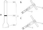
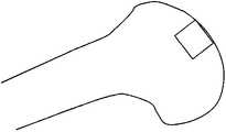
图2为本发明的取骨柱结构示意图;Fig. 2 is the structural representation of the bone column of the present invention;
图3为本发明的塑形柱结构示意图;FIG. 3 is a schematic diagram of the structure of the shaping column of the present invention;
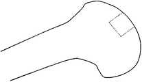
图4为本发明的设想的几种软骨缺损形状及配套骨软骨移植器底端形状设计图;Fig. 4 is the design drawing of several cartilage defect shapes envisaged by the present invention and the shape of the bottom end of the supporting osteochondral transplanter;
图5为本发明的衔接杆及其与塑形柱、取骨柱的组合图;Fig. 5 is the connecting rod of the present invention and its combination with the shaping column and the bone taking column;
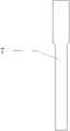
图6为本发明的螺纹推杆及其与塑形柱、取骨柱、衔接杆组合图;Fig. 6 is the threaded push rod of the present invention and its combination with the shaping column, the bone taking column and the connecting rod;
图7为本发明的光滑推杆及其与塑形柱、取骨柱、衔接杆组合图;Fig. 7 is a smooth push rod of the present invention and its combination with a shaping column, a bone taking column, and a connecting rod;
图8为本发明的骨柱递送管结构示意图;8 is a schematic structural diagram of the bone column delivery tube of the present invention;
图9为本发明的骨柱递送杆结构示意图;Fig. 9 is the structural schematic diagram of the bone column delivery rod of the present invention;
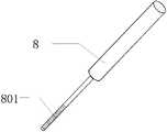
图10为本发明的测深器结构示意图;Fig. 10 is the structural schematic diagram of the depth sounder of the present invention;
图11为本发明的缺损塑形过程图;Fig. 11 is the defect shaping process diagram of the present invention;
图12为本发明的缺损处骨柱取出示意图;Figure 12 is a schematic diagram of the bone column removal from the defect of the present invention;
图13为本发明的缺损处塑形效果图;Fig. 13 is the shaping effect diagram of the defect of the present invention;
图14为本发明的获取骨软骨移植物过程图;Figure 14 is a process diagram of obtaining an osteochondral graft of the present invention;
图15为本发明的骨软骨移植物取出示意图;Figure 15 is a schematic diagram of the osteochondral graft removal of the present invention;
图16为本发明的测深器测量缺损处深度图;Fig. 16 is the depth map of the depth of the defect measured by the depth sounder of the present invention;
图17为本发明的骨软骨移植物移植图;Fig. 17 is the osteochondral graft transplantation diagram of the present invention;
图18为本发明的移植后效果图;Fig. 18 is the effect diagram after transplantation of the present invention;
图19为本发明的螺纹推杆装配图;Fig. 19 is the assembly drawing of the threaded push rod of the present invention;
图20为本发明的光滑推杆装配图。Figure 20 is an assembly view of the smooth push rod of the present invention.
图中标号说明:Description of the labels in the figure:
1、取骨柱;101、第一推杆入口;102、第一手柄;103、第一内螺纹;104、第一中空管道;105、第一出料孔;106、第一刻度尺;107、第一骨柱入口;2、塑形柱;201、第二推杆入口;202、第二手柄;203、第二内螺纹;204、第二中空管道;205、第二出料孔;206、第二刻度尺;207、第二骨柱入口;3、衔接杆;301、衔接杆圆头;302、衔接杆橡胶圈凹槽;303、衔接杆平头;4、螺纹推杆;401、螺纹推杆手柄;402、外螺纹;403、螺纹推杆柄;404、螺纹推杆前头;5、光滑推杆;501、光滑推杆平头;502、光滑推杆柄;503、推杆橡胶圈凹槽;504、光滑推杆前头;6、骨柱递送管;7、骨柱递送杆;8、测深器;801、测深器刻度尺。1. Bone extraction column; 101, the first push rod inlet; 102, the first handle; 103, the first internal thread; 104, the first hollow pipe; 105, the first discharge hole; 106, the first scale; 107, the first bone column inlet; 2, the shaping column; 201, the second push rod inlet; 202, the second handle; 203, the second internal thread; 204, the second hollow pipe; 205, the second discharge hole; 206, the second scale; 207, the entrance of the second bone column; 3, the connecting rod; 301, the round head of the connecting rod; 302, the rubber ring groove of the connecting rod; 303, the flat head of the connecting rod; 4, the threaded push rod; 401, Threaded push rod handle; 402, external thread; 403, threaded push rod handle; 404, threaded push rod front; 5, smooth push rod; 501, smooth push rod flat head; 502, smooth push rod handle; 503, push rod rubber ring groove; 504, smooth push rod front; 6, bone column delivery tube; 7, bone column delivery rod; 8, depth sounder; 801, depth sounder scale.
具体实施方式Detailed ways
下面将结合本发明实施例中的附图,对本发明实施例中的技术方案进行清楚、完整地描述,显然,所描述的实施例仅仅是本发明一部分实施例,而不是全部的实施例。基于本发明中的实施例,本领域普通技术人员在没有做出创造性劳动前提下所获得的所有其他实施例,都属于本发明保护的范围。The technical solutions in the embodiments of the present invention will be clearly and completely described below with reference to the accompanying drawings in the embodiments of the present invention. Obviously, the described embodiments are only a part of the embodiments of the present invention, but not all of the embodiments. Based on the embodiments of the present invention, all other embodiments obtained by those of ordinary skill in the art without creative efforts shall fall within the protection scope of the present invention.
请参阅图1-图20,本发明提供一种个性化金属3D打印骨软骨移植器械,包括取骨柱1、塑形柱2、衔接杆3、螺纹推杆4、光滑推杆5、骨柱递送管6、骨柱递送杆7和测深器8。Please refer to FIGS. 1-20 , the present invention provides a personalized metal 3D printed osteochondral implantation device, including a
其中,取骨柱1用于获取骨软骨移植物。Among them, the
塑形柱2用于对软骨缺损处进行修整,保证缺损形状及深度与取骨柱1获取的骨软骨移植物一致。The
衔接杆3用于放置于取骨柱1及塑形柱2的中空管道内,起到衔接骨软骨移植物与推杆的作用,当推杆向前推进时,带动衔接杆3移动,从而将骨软骨移植物推出。The connecting
螺纹推杆4用于将推杆向前移动,通过衔接杆3将塑形柱2或取骨柱1内的骨柱推出管道。The threaded
光滑推杆5作用同螺纹推杆4,与螺纹推杆4不同的是,光滑推杆5无螺纹结构,插入到中空管道后,可迅速与衔接杆前头接触,随后对光滑推杆5的平头施压,将骨柱推出。但光滑推杆5仅适用于小骨柱,不适用于较大尺寸的骨柱。因为,螺纹推杆4可以通过旋拧,产生的力度明显大于光滑推杆5的作用力,为了防止过大冲击损伤骨柱的软骨面,应避免使用骨锤锤击光滑推杆5的平头,遂只能使用手指按压,所以产生的推力明显小于螺纹推杆4。The function of the
骨柱递送管6用于将骨软骨移植物递送至缺损处。The bone
骨柱递送杆7用于将骨软骨移植物推入缺损内,如果需要,可以使用骨锤轻击递送杆,从而保证移植物完全进入缺损内。The bone
测深器8用于测量制造的缺损深度,与获取的骨软骨移植物的厚度比较,从而保证骨软骨移植物精确放置到缺损内,避免出现移植物高出或低于周边软骨面的情况。The
通过使用3.0T核磁共振仪器进行膝关节扫描,获取膝关节核磁共振图像,核磁共振扫描序列为PD-FSE-SPIR,具体参数为:重复时间:2915.0毫秒,回波时间:39.4毫秒。随后将获取的膝关节核磁二维图像导入医学逆向软件Mimics软件,将采取以下步骤进行软骨组织分割及三维模型重建。i.利用“编辑蒙罩”,“画笔”功能,利用软骨组织与其他组织的灰度差,勾勒出软骨的基本轮廓,并且结合图像矢状位、冠状位进行调整,以最大程度勾勒出真实软骨的轮廓;ii.利用“区域增长”功能建立软骨“蒙版”,选中此项功能后,通过点击软骨组织,即可将软骨内部组织全部选中,而软骨之外的组织则被剔除,从而保证后期更加准确的重建软骨三维模型;iii.建立“蒙版”后,利用“三维重建”功能即可构建软骨三维模型,然后导出STL格式,随后将STL格式的软骨三维模型导入Geomagic软件,删除模型表面钉状物,进行三角面片优化处理,进一步优化模型表面质量,随后导出STL格式文件。将软骨模型STL格式文件导入医学逆向工程软件SOLIDWORKS软件,结合软骨缺损形状,设计配套的骨软骨移植器械包括以上所提到的取骨柱1、塑形柱2、衔接杆3、螺纹推杆4、光滑推杆5、骨柱递送管6、骨柱递送杆7和测深器8。The knee joint was scanned by using a 3.0T nuclear magnetic resonance apparatus to obtain a knee joint magnetic resonance image. The magnetic resonance scanning sequence was PD-FSE-SPIR, and the specific parameters were: repetition time: 2915.0 milliseconds, echo time: 39.4 milliseconds. Then, the acquired 2D MRI image of the knee joint is imported into the medical inverse software Mimics software, and the following steps will be taken for cartilage tissue segmentation and 3D model reconstruction. i. Use the functions of "Edit Mask" and "Brush" to outline the basic outline of the cartilage by using the grayscale difference between the cartilage tissue and other tissues, and adjust the sagittal and coronal positions of the image to outline the real image to the greatest extent. The outline of cartilage; ii. Use the "regional growth" function to create a cartilage "mask", after selecting this function, by clicking on the cartilage tissue, all the internal cartilage tissue can be selected, while the tissue outside the cartilage is eliminated, thus To ensure a more accurate reconstruction of the cartilage 3D model in the later stage; iii. After establishing the "mask", use the "3D reconstruction" function to build a cartilage 3D model, then export the STL format, and then import the STL format cartilage 3D model into Geomagic software, delete Pins on the model surface are optimized for triangular patches to further optimize the surface quality of the model, and then export the STL format file. Import the cartilage model STL format file into the medical reverse engineering software SOLIDWORKS software, and combine the shape of the cartilage defect to design the supporting osteochondral transplantation instruments, including the above-mentioned
取骨柱1和塑形柱2一端分别开设有第一推杆入口101和第二推杆入口201,取骨柱1和塑形柱2另一端分别开设有第一骨柱入口107和第二骨柱入口207,取骨柱1和塑形柱2内部分别开设有第一内螺纹103和第二内螺纹203,取骨柱1和塑形柱2内部分别开设有第一中空管道104和第二中空管道204,取骨柱1和塑形柱2一端侧壁分别开设有第一出料孔105和第二出料孔205,取骨柱1和塑形柱2一端侧壁分别开设有第一刻度尺106和第二刻度尺206,衔接杆3分别活动安装在取骨柱1和塑形柱2内部,螺纹推杆4一端分别活动安装在取骨柱1和塑形柱2内部,光滑推杆5一端分别活动安装在取骨柱1和塑形柱2内部,取骨柱1一端固定安装有第一手柄102,塑形柱2一端固定安装有第二手柄202;其中取骨柱1和塑形柱2结构类似,塑形柱2前端开口的外径与取骨柱1前端开口的内径一致,从而保证骨软骨移植物供体与缺损区域紧密嵌合,第一推杆入口101和第二推杆入口201用于螺纹推杆4及光滑推杆5从此入口进入,第一手柄102和第二手柄202用于握持器械,便于将骨软骨移植物取出,第一内螺纹103和第二内螺纹203用于与螺纹推杆4的螺纹匹配,第一中空管道104和第二中空管道204用于衔接杆3及推杆在此管道内滑动,第一出料孔105和第二出料孔205用于获取骨软骨移植物过程中,可供骨渣或血液流出的孔道,第一刻度尺106和第二刻度尺206用于实时观察取骨柱1楔入深入,从而确定骨软骨移植物获取厚度,第一骨柱入口107和第二骨柱入口207用于与供应区域的软骨面接触,获取的骨软骨移植物从此入口进入,其中取骨柱1、塑形柱2、衔接杆3、螺纹推杆4、光滑推杆5均采用不锈钢制成,骨柱递送管6透明树脂制成。骨柱递送杆7和测深器8采用树脂制成。One end of the
按照个性化定制骨软骨移植器械,使用塑形柱2对缺损区域进行修整,主要目的是将缺损处的软骨下骨取出,将衔接杆3前段全部推入中空管道内,塑形柱2前端对准、且垂直于缺损面,并保证与缺损面吻合,使用骨锤锤击塑形柱2的另一端,锤击过程注意观察刻度尺,骨柱深度一般为10-15mm,到达目标深度后,停止锤击,将塑形柱2分别向四周均匀倾斜,使骨柱与侧壁及底端骨组织完全分离,随后拔出塑形柱2,最后,使用螺纹推杆4或光滑推杆5将骨柱推出,即可完成对缺损区域的塑形,然后获取骨软骨移植物,使用取骨柱1在关节非负重区获取与缺损形状及深度匹配的骨软骨移植物。将衔接杆3前段全部推入中空管道内,在关节非负重区寻找合适的供体位置,取骨柱1前端对准、且垂直于软骨面,随后使用骨锤锤击取骨柱1,注意观察前端刻度尺,待到达与缺损一致的深度,停止锤击,将取骨柱1分别向四周均匀倾斜,使骨柱与侧壁及底端骨组织完全分离,随后拔出取骨柱1,最后,使用螺纹推杆4或光滑推杆5将骨柱推出,即可获得与缺损匹配的骨软骨移植物。According to the personalized osteochondral transplantation instrument, use the
最后进行骨软骨移植物移植,使用测深器8测量缺损深度,并与获取的骨软骨移植物厚度进行比较,当移植物厚度与缺损深度匹配时,即可进行下一步移植,若移植物厚度与缺损深度存在偏差较大,需要对缺损或移植物进行修整后进行移植,移植时,将骨软骨移植物放入与缺损形状匹配,3D打印的透明骨柱递送管6内,骨柱递送管6的前端对准缺损面,使用骨柱递送杆7将骨软骨移植物推入缺损处,若遇到阻力较大,可使用骨锤轻敲骨柱递送杆7,使移植物完全进入缺损处,保证移植物与缺损完整契合。Finally, the osteochondral graft is transplanted, and the depth of the defect is measured by the
在一些实施例中,参阅图5,衔接杆3包括衔接杆圆头301、衔接杆橡胶圈凹槽302和衔接杆平头303,衔接杆圆头301开设在衔接杆3一端,衔接杆橡胶圈凹槽302开设在衔接杆3一端外壁,衔接杆平头303开设在衔接杆3另一端,衔接杆圆头301与螺纹推杆4及光滑推杆5的前头衔接,衔接杆平头303与骨软骨移植物的软骨面衔接,衔接杆橡胶圈凹槽302可容纳橡胶圈,橡胶圈与取骨柱1或塑形柱2的中空管道侧壁衔接,增加摩擦力,防止衔接杆3在中空管道内随意滑动。In some embodiments, referring to FIG. 5 , the connecting
在一些实施例中,参阅图6、图7,螺纹推杆4包括螺纹推杆手柄401、外螺纹402、螺纹推杆柄403和螺纹推杆前头404,螺纹推杆手柄401开设在螺纹推杆4一端,且螺纹推杆手柄401固定连接在螺纹推杆柄403一端,外螺纹402开设在螺纹推杆柄403一端外壁螺纹推杆前头404开设在螺纹推杆柄403一端,光滑推杆5包括光滑推杆平头501、光滑推杆柄502、推杆橡胶圈凹槽503和光滑推杆前头504,光滑推杆平头501开设在光滑推杆5一端,且光滑推杆平头501固定连接在光滑推杆柄502一端,推杆橡胶圈凹槽503开设在光滑推杆柄502一端外壁,光滑推杆平头501开设在光滑推杆柄502一端,螺纹推杆柄403一端分别活动安装在取骨柱1和塑形柱2内侧,且螺纹推杆柄403外径分别和取骨柱1和塑形柱2内径相适配,外螺纹402分别与第一内螺纹103和第二内螺纹203相适配,光滑推杆柄502一端分别活动安装在取骨柱1和塑形柱2内侧,且光滑推杆柄502外径分别和取骨柱1和塑形柱2内径相适配;螺纹推杆前头404和光滑推杆前头504与衔接杆3的圆头通过一突一凹衔接,外螺纹402与取骨柱1或塑形柱2上段的螺纹匹配,螺纹推杆手柄401方便旋转推杆,推杆橡胶圈凹槽503的作用是可容纳橡胶圈,橡胶圈与取骨柱1或塑形柱2的中空管道侧壁衔接,增加摩擦力,防止光滑推杆5随意移动。In some embodiments, referring to FIGS. 6 and 7 , the threaded
在一些实施例中,参阅图19、图20,衔接杆圆头301和螺纹推杆前头404相适配,且衔接杆圆头301和光滑推杆前头504相适配;衔接杆圆头301和螺纹推杆前头404以及光滑推杆前头504采用一突一凹方式衔接。In some embodiments, referring to FIGS. 19 and 20 , the
在一些实施例中,参阅图7、图8、图17,骨柱递送杆7一端和骨柱递送管6一端相适配,测深器8一端开设有测深器刻度尺801。In some embodiments, referring to FIG. 7 , FIG. 8 , and FIG. 17 , one end of the bone
本发明的工作流程及原理为:The work flow and principle of the present invention are:
S1:首先使用3.0T核磁共振仪器进行膝关节扫描,获取膝关节核磁共振图像,核磁共振扫描序列为PD-FSE-SPIR,具体参数为:重复时间:2915.0毫秒,回波时间:39.4毫秒。随后将获取的膝关节核磁二维图像导入医学逆向软件Mimics软件,将采取以下步骤进行软骨组织分割及三维模型重建。i.利用“编辑蒙罩”,“画笔”功能,利用软骨组织与其他组织的灰度差,勾勒出软骨的基本轮廓,并且结合图像矢状位、冠状位进行调整,以最大程度勾勒出真实软骨的轮廓;ii.利用“区域增长”功能建立软骨“蒙版”,选中此项功能后,通过点击软骨组织,即可将软骨内部组织全部选中,而软骨之外的组织则被剔除,从而保证后期更加准确的重建软骨三维模型;iii.建立“蒙版”后,利用“三维重建”功能即可构建软骨三维模型,然后导出STL格式,随后将STL格式的软骨三维模型导入Geomagic软件,删除模型表面钉状物,进行三角面片优化处理,进一步优化模型表面质量,随后导出STL格式文件。将软骨模型STL格式文件导入医学逆向工程软件SOLIDWORKS软件,结合软骨缺损形状,设计配套的骨软骨移植器械;S1: First, use a 3.0T MRI instrument to scan the knee joint to obtain an MRI image of the knee joint. The MRI scan sequence is PD-FSE-SPIR, and the specific parameters are: repetition time: 2915.0 milliseconds, echo time: 39.4 milliseconds. Then, the acquired 2D MRI image of the knee joint is imported into the medical inverse software Mimics software, and the following steps will be taken for cartilage tissue segmentation and 3D model reconstruction. i. Use the functions of "Edit Mask" and "Brush" to outline the basic outline of the cartilage by using the grayscale difference between the cartilage tissue and other tissues, and adjust the sagittal and coronal positions of the image to outline the real image to the greatest extent. The outline of cartilage; ii. Use the "regional growth" function to create a cartilage "mask", after selecting this function, by clicking on the cartilage tissue, all the internal cartilage tissue can be selected, while the tissue outside the cartilage is eliminated, thus To ensure a more accurate reconstruction of the cartilage 3D model in the later stage; iii. After establishing the "mask", use the "3D reconstruction" function to build a cartilage 3D model, then export the STL format, and then import the STL format cartilage 3D model into Geomagic software, delete Pins on the model surface are optimized for triangular patches to further optimize the surface quality of the model, and then export the STL format file. Import the cartilage model STL format file into the medical reverse engineering software SOLIDWORKS software, and combine the shape of the cartilage defect to design the supporting osteochondral transplantation instrument;
S2:进行缺损塑形,按照个性化定制骨软骨移植器械,使用塑形柱2对缺损区域进行修整,主要目的是将缺损处的软骨下骨取出,将衔接杆3前段全部推入中空管道内,塑形柱2前端对准、且垂直于缺损面,并保证与缺损面吻合,使用骨锤锤击塑形柱2的另一端,锤击过程注意观察刻度尺,骨柱深度一般为10-15mm,到达目标深度后,停止锤击,将塑形柱2分别向四周均匀倾斜,使骨柱与侧壁及底端骨组织完全分离,随后拔出塑形柱2,最后,使用螺纹推杆4或光滑推杆5将骨柱推出,即可完成对缺损区域的塑形;S2: Carry out defect shaping, customize the osteochondral transplantation device according to the individual, and use the
S3:获取骨软骨移植物,使用取骨柱1在关节非负重区获取与缺损形状及深度匹配的骨软骨移植物。将衔接杆3前段全部推入中空管道内,在关节非负重区寻找合适的供体位置,取骨柱1前端对准、且垂直于软骨面,随后使用骨锤锤击取骨柱1,注意观察前端刻度尺,待到达与缺损一致的深度,停止锤击,将取骨柱1分别向四周均匀倾斜,使骨柱与侧壁及底端骨组织完全分离,随后拔出取骨柱1,最后,使用螺纹推杆4或光滑推杆5将骨柱推出,即可获得与缺损匹配的骨软骨移植物;S3: Obtain an osteochondral graft, and use the
S4:进行骨软骨移植物移植,使用测深器8测量缺损深度,并与获取的骨软骨移植物厚度进行比较,当移植物厚度与缺损深度匹配时,即可进行下一步移植,若移植物厚度与缺损深度存在偏差较大,需要对缺损或移植物进行修整后进行移植,移植时,将骨软骨移植物放入与缺损形状匹配,3D打印的透明骨柱递送管6内,骨柱递送管6的前端对准缺损面,使用骨柱递送杆7将骨软骨移植物推入缺损处,若遇到阻力较大,可使用骨锤轻敲骨柱递送杆7,使移植物完全进入缺损处,保证移植物与缺损完整契合。S4: Carry out osteochondral graft transplantation, use the
以上公开的本发明优选实施例只是用于帮助阐述本发明。优选实施例并没有详尽叙述所有的细节,也不限制该发明仅为所述的具体实施方式。显然,根据本说明书的内容,可作很多的修改和变化。本说明书选取并具体描述这些实施例,是为了更好地解释本发明的原理和实际应用,从而使所属技术领域技术人员能很好地理解和利用本发明。本发明仅受权利要求书及其全部范围和等效物的限制。The above-disclosed preferred embodiments of the present invention are provided only to help illustrate the present invention. The preferred embodiments do not exhaust all the details, nor do they limit the invention to only the described embodiments. Obviously, many modifications and variations are possible in light of the content of this specification. These embodiments are selected and described in this specification in order to better explain the principles and practical applications of the present invention, so that those skilled in the art can well understand and utilize the present invention. The present invention is to be limited only by the claims and their full scope and equivalents.
Claims (9)
Translated fromChinesePriority Applications (1)
| Application Number | Priority Date | Filing Date | Title |
|---|---|---|---|
| CN202211133834.0ACN115192273A (en) | 2022-09-19 | 2022-09-19 | A personalized metal 3D printing osteochondral transplantation device and method |
Applications Claiming Priority (1)
| Application Number | Priority Date | Filing Date | Title |
|---|---|---|---|
| CN202211133834.0ACN115192273A (en) | 2022-09-19 | 2022-09-19 | A personalized metal 3D printing osteochondral transplantation device and method |
Publications (1)
| Publication Number | Publication Date |
|---|---|
| CN115192273Atrue CN115192273A (en) | 2022-10-18 |
Family
ID=83572701
Family Applications (1)
| Application Number | Title | Priority Date | Filing Date |
|---|---|---|---|
| CN202211133834.0APendingCN115192273A (en) | 2022-09-19 | 2022-09-19 | A personalized metal 3D printing osteochondral transplantation device and method |
Country Status (1)
| Country | Link |
|---|---|
| CN (1) | CN115192273A (en) |
Citations (7)
| Publication number | Priority date | Publication date | Assignee | Title |
|---|---|---|---|---|
| CN203280508U (en)* | 2013-06-04 | 2013-11-13 | 江苏百得医疗器械有限公司 | Surgical instrument package for bone grafting |
| US20160250042A1 (en)* | 2015-02-27 | 2016-09-01 | In2Bones Usa, Llc | Engineered sterile cartilage allograft implant plug with sterile, specific instrument kit(s) |
| CN107073175A (en)* | 2014-09-09 | 2017-08-18 | 慕尼黑工业大学伊萨尔河右岸医院 | Medical/surgical implant |
| CN110236739A (en)* | 2019-07-19 | 2019-09-17 | 北京万洁天元医疗器械股份有限公司 | A kind of articular cartilage recovery support molding machine and preparation method thereof |
| CN110301968A (en)* | 2019-07-31 | 2019-10-08 | 熊海阔 | A kind of bone and cartilage fixator and its application method |
| CN210673420U (en)* | 2019-06-12 | 2020-06-05 | 上海市第六人民医院 | A cartilage is transplanted and is used apparatus suit for bone surgery |
| CN213489567U (en)* | 2020-08-07 | 2021-06-22 | 山西医科大学第二医院 | Multifunctional osteochondral transplantation device |
- 2022
- 2022-09-19CNCN202211133834.0Apatent/CN115192273A/enactivePending
Patent Citations (7)
| Publication number | Priority date | Publication date | Assignee | Title |
|---|---|---|---|---|
| CN203280508U (en)* | 2013-06-04 | 2013-11-13 | 江苏百得医疗器械有限公司 | Surgical instrument package for bone grafting |
| CN107073175A (en)* | 2014-09-09 | 2017-08-18 | 慕尼黑工业大学伊萨尔河右岸医院 | Medical/surgical implant |
| US20160250042A1 (en)* | 2015-02-27 | 2016-09-01 | In2Bones Usa, Llc | Engineered sterile cartilage allograft implant plug with sterile, specific instrument kit(s) |
| CN210673420U (en)* | 2019-06-12 | 2020-06-05 | 上海市第六人民医院 | A cartilage is transplanted and is used apparatus suit for bone surgery |
| CN110236739A (en)* | 2019-07-19 | 2019-09-17 | 北京万洁天元医疗器械股份有限公司 | A kind of articular cartilage recovery support molding machine and preparation method thereof |
| CN110301968A (en)* | 2019-07-31 | 2019-10-08 | 熊海阔 | A kind of bone and cartilage fixator and its application method |
| CN213489567U (en)* | 2020-08-07 | 2021-06-22 | 山西医科大学第二医院 | Multifunctional osteochondral transplantation device |
Similar Documents
| Publication | Publication Date | Title |
|---|---|---|
| US7591820B2 (en) | Retrograde osteochondral autograft transfer system | |
| CN106923936A (en) | The design preparation method of the personalized customization 3D printing porous titanium alloy segmental prosthese rebuild for large segmental bone defect | |
| US20180340149A1 (en) | Method for culturing osteocyte | |
| CN101474426B (en) | Vascular matrix for removing cells in vascular tissue and preparation method thereof | |
| Rudzinska | An electron microscope study of the contractile vacuole in Tokophrya infusionum | |
| CN109182249B (en) | Preparation method of scaffold material for cell transplantation for in vivo repair | |
| Meng et al. | Decellularized laser micro-patterned osteochondral implants exhibit zonal recellularization and self-fixing for osteochondral regeneration in a goat model | |
| CN103223194A (en) | Cartilage graft for cartilage injury repair and preparation method thereof | |
| CN219042822U (en) | A Personalized Metal 3D Printed Osteochondral Graft Device | |
| CN115192273A (en) | A personalized metal 3D printing osteochondral transplantation device and method | |
| US8852923B2 (en) | Flow-stretch-flexure bioreactor | |
| CN102078642A (en) | Articular cartilage restoration and regeneration stent and preparation method thereof | |
| Vaegler et al. | Tissue engineering in urothelium regeneration | |
| CN111249529B (en) | Bionic multilayer collagen scaffold for cartilage repair and preparation method thereof | |
| CN109954165B (en) | Tissue engineering blood vessel construction method without stent | |
| CN103948457A (en) | Method for constructing regenerated nerve vascularized bones, cartilages, joints or body surface organs | |
| CN113768668B (en) | A modeling method for designing personalized medical mandible model based on TPMS | |
| CN109072188A (en) | Activated stem cell manufacturing method | |
| CN106421915A (en) | Method of repairing human articular cartilage based on 3D bioprinting | |
| CN101822851B (en) | Preparation method of tissue engineered bone cartilage frame | |
| CN113332495A (en) | Three-dimensional vascularized tissue engineering bone and preparation method thereof | |
| CN107320778A (en) | A kind of preparation method of cartilage acellular matrix | |
| JP2008307186A (en) | Jaw bone graft material used for jaw bone regeneration and method for producing the same | |
| CN110841106A (en) | Method for designing and preparing personalized segmental bone implant based on selective laser melting technology | |
| Rye | Microneedle arrays for injection seeding of tissue engineered scaffolds |
Legal Events
| Date | Code | Title | Description |
|---|---|---|---|
| PB01 | Publication | ||
| PB01 | Publication | ||
| SE01 | Entry into force of request for substantive examination | ||
| SE01 | Entry into force of request for substantive examination |