CN115192133A - A Cardiovascular Intubation Nursing Holder - Google Patents
A Cardiovascular Intubation Nursing HolderDownload PDFInfo
- Publication number
- CN115192133A CN115192133ACN202210730198.3ACN202210730198ACN115192133ACN 115192133 ACN115192133 ACN 115192133ACN 202210730198 ACN202210730198 ACN 202210730198ACN 115192133 ACN115192133 ACN 115192133A
- Authority
- CN
- China
- Prior art keywords
- rod
- clamping rod
- clamping
- plate
- driving rod
- Prior art date
- Legal status (The legal status is an assumption and is not a legal conclusion. Google has not performed a legal analysis and makes no representation as to the accuracy of the status listed.)
- Granted
Links
Images


Classifications
- A—HUMAN NECESSITIES
- A61—MEDICAL OR VETERINARY SCIENCE; HYGIENE
- A61B—DIAGNOSIS; SURGERY; IDENTIFICATION
- A61B17/00—Surgical instruments, devices or methods
- A61B17/28—Surgical forceps
- A61B17/2812—Surgical forceps with a single pivotal connection
- A61B17/282—Jaws
- A—HUMAN NECESSITIES
- A61—MEDICAL OR VETERINARY SCIENCE; HYGIENE
- A61M—DEVICES FOR INTRODUCING MEDIA INTO, OR ONTO, THE BODY; DEVICES FOR TRANSDUCING BODY MEDIA OR FOR TAKING MEDIA FROM THE BODY; DEVICES FOR PRODUCING OR ENDING SLEEP OR STUPOR
- A61M25/00—Catheters; Hollow probes
- A61M25/01—Introducing, guiding, advancing, emplacing or holding catheters
Landscapes
- Health & Medical Sciences (AREA)
- Life Sciences & Earth Sciences (AREA)
- Surgery (AREA)
- Public Health (AREA)
- Engineering & Computer Science (AREA)
- Veterinary Medicine (AREA)
- Biomedical Technology (AREA)
- Heart & Thoracic Surgery (AREA)
- General Health & Medical Sciences (AREA)
- Animal Behavior & Ethology (AREA)
- Hematology (AREA)
- Pulmonology (AREA)
- Anesthesiology (AREA)
- Ophthalmology & Optometry (AREA)
- Nuclear Medicine, Radiotherapy & Molecular Imaging (AREA)
- Biophysics (AREA)
- Medical Informatics (AREA)
- Molecular Biology (AREA)
- Infusion, Injection, And Reservoir Apparatuses (AREA)
- External Artificial Organs (AREA)
Abstract
Description
Translated fromChinese技术领域technical field
本发明涉及医疗器械相关技术领域,具体为一种心血管插管护理夹持器。The invention relates to the related technical field of medical devices, in particular to a cardiovascular intubation nursing holder.
背景技术Background technique
对患者进行心脏或血管手术过程中,一般需要借助夹持器对心血管进行插管,以满足心脏等手术的要求,保障手术的正常进行。During cardiac or vascular surgery on a patient, it is generally necessary to use a gripper to intubate the cardiovascular system to meet the requirements of cardiac and other surgeries and ensure the normal operation of the surgery.
然而现有的心血管插管护理夹持器还存在以下问题:However, the existing cardiovascular intubation care holders still have the following problems:
在公开号为CN211301676U的一种新型心血管插管夹持器中,“包括相互交叉的夹持杆一和夹持杆……通过紧固螺纹杆的推动带动滑动柱和弧形夹块对插管进行固定稳定,方便不同直径插管的夹持工作”,该夹持器在使用时需要在两个夹持弧上分别转动紧固螺纹杆带动弧形夹块进行移动,促使贴合于插管侧部,实现不同直径插管的夹持工作,然而该夹持器在实际操作过程中,使用较为不便,调节步骤较为繁琐,同时夹持器一般由医护人员手动夹持,在长期操作下,手部容易出现抖动等情况,导致夹持力度出现浮动,从而将导致插管出现掉落的情况,进而将影响心血管插管作业的正常进行。In a new type of cardiovascular intubation holder with publication number CN211301676U, "comprising a
所以我们提出了一种心血管插管护理夹持器,以便于解决上述中提出的问题。Therefore, we propose a cardiovascular intubation care holder in order to solve the problems raised above.
发明内容SUMMARY OF THE INVENTION
本发明的目的在于提供一种心血管插管护理夹持器,以解决上述背景技术提出的目前市场上现有的心血管插管护理夹持器在对不同直径插管进行夹持时操作较为不便,同时容易受医护人员状态影响,出现掉落的情况,影响插管作业的正常进行的问题。The purpose of the present invention is to provide a cardiovascular intubation nursing holder, so as to solve the problem that the existing cardiovascular intubation nursing holder on the market proposed by the above-mentioned background technology is relatively difficult to operate when clamping intubations of different diameters. It is inconvenient, and at the same time, it is easily affected by the state of the medical staff, and there is a problem of falling, which affects the normal progress of the intubation operation.
为实现上述目的,本发明提供如下技术方案:一种心血管插管护理夹持器,包括第一夹持杆和第二夹持杆,所述第一夹持杆和第二夹持杆的中部之间为活动轴连接,且第一夹持杆和第二夹持杆的右端均开设有手指可以伸入的通孔;In order to achieve the above objects, the present invention provides the following technical solutions: a cardiovascular intubation care holder, comprising a first clamping rod and a second clamping rod, the first clamping rod and the second clamping rod are The middle part is connected by a movable shaft, and the right ends of the first clamping rod and the second clamping rod are provided with through holes into which fingers can be inserted;
两个夹持弧,其分别安装于所述第一夹持杆和第二夹持杆的左端,且两个夹持弧构成一个圆环设置,可以套设在心血管插管的外侧;two clamping arcs, which are respectively installed on the left ends of the first clamping rod and the second clamping rod, and the two clamping arcs form a circular ring, which can be sleeved on the outside of the cardiovascular cannula;
还包括有:Also includes:
固定座,其固定安装于所述第一夹持杆的上端,且固定座右侧轴承安装有螺纹杆,并且螺纹杆的右端连接有转动块,医护人员通过转动块可以带动螺纹杆进行转动;a fixed seat, which is fixedly installed on the upper end of the first clamping rod, a threaded rod is installed on the right bearing of the fixed seat, and a rotating block is connected to the right end of the threaded rod, and the medical staff can drive the threaded rod to rotate through the rotating block;
第一驱动杆和第二驱动杆,其分别贴合设置于所述第一夹持杆和第二夹持杆的内部,且第一驱动杆和第二驱动杆两者之间通过连接组件实现连接;The first driving rod and the second driving rod are respectively fitted and arranged inside the first clamping rod and the second clamping rod, and the connection between the first driving rod and the second driving rod is realized by connecting components connect;
两个连通板,其分别固定安装于所述第一夹持杆和第二夹持杆的内部;two communication plates, which are respectively fixedly installed inside the first clamping rod and the second clamping rod;
两个横杆,其分别卡合滑动设置于所述第一夹持杆和第二夹持杆的内部,且横杆的左右两端分别安装有定位板和活塞板。Two transverse rods are respectively fitted and slidably arranged inside the first clamping rod and the second clamping rod, and the left and right ends of the transverse rods are respectively provided with a positioning plate and a piston plate.
优选的,所述第一驱动杆螺纹套设在螺纹杆的外侧,且第一驱动杆的横向截面长度小于所述第二驱动杆横向截面长度,使得当转动块带动螺纹杆转动后,可以带动第一驱动杆进行移动,并且使得可以将第二驱动杆上所安装的连接块移动至第一驱动杆的外侧,从而实现第一夹持杆和第二夹持杆之间的转动,以便将插管置于两个夹持弧之间。Preferably, the first driving rod is threadedly sleeved on the outside of the threaded rod, and the length of the transverse section of the first driving rod is smaller than the length of the transverse section of the second driving rod, so that when the rotating block drives the threaded rod to rotate, it can drive the threaded rod to rotate. The first driving rod moves, and makes it possible to move the connecting block mounted on the second driving rod to the outside of the first driving rod, so as to realize the rotation between the first clamping rod and the second clamping rod, so that the The cannula is placed between the two clamping arcs.
优选的,所述连接组件由固定板、H字形板、连动块和防脱块组成,且固定板位于所述第二驱动杆的外侧,并且固定板的前侧安装有H字形板,而且H字形板的侧部安装有四个连动块,位于上方的两个连动块贴合设置于所述第一驱动杆的两侧内部,且位于下方的两个连动块贴合设置于所述第二驱动杆的两侧内部,使得可以在四个连动块的作用下,可以对第一驱动杆和第二驱动杆进行连接,即实现第一夹持杆和第二夹持杆的固定作用,从而避免第一夹持杆和第二夹持杆受到外力影响发生相对转动,保证插管的顺利进行。Preferably, the connecting assembly is composed of a fixing plate, an H-shaped plate, a linkage block and an anti-separation block, and the fixing plate is located outside the second driving rod, and an H-shaped plate is installed on the front side of the fixing plate, and Four linkage blocks are installed on the side of the H-shaped plate, the two linkage blocks located at the top are attached to the inside of both sides of the first drive rod, and the two linkage blocks located at the bottom are attached to the Inside the two sides of the second driving rod, the first driving rod and the second driving rod can be connected under the action of the four interlocking blocks, that is, the first clamping rod and the second clamping rod can be realized. Therefore, the relative rotation of the first clamping rod and the second clamping rod under the influence of external force is avoided, and the smooth intubation is ensured.
优选的,所述第二驱动杆的上端卡合滑动设置有两个截面呈梯形设置的防脱块,且两个防脱块分别安装于位于下方的两个连动块的下部,使得可以在防脱块的作用下,促使连接组件可以在第二驱动杆上进行滑动的同时,避免出现掉落和丢失的情况。Preferably, two anti-separation blocks with trapezoidal cross-sections are arranged on the upper end of the second driving rod to engage and slide, and the two anti-separation blocks are respectively installed at the lower parts of the two linkage blocks located below, so that the Under the action of the anti-separation block, the connecting assembly can be slid on the second driving rod, and the situation of falling and loss can be avoided.
优选的,所述横杆的左右两端与定位板和活塞板之间分别为活动轴连接和固定连接,且定位板为弧形结构设置,并且定位板的右侧安装有硅胶垫,使得横杆、定位板和活塞板可以进行同步移动,且定位板可以在移动过程中,实现对插管的固定作业的同时,减少对插管的破坏。Preferably, the left and right ends of the transverse rod and the positioning plate and the piston plate are respectively connected by movable shafts and fixedly connected, and the positioning plate is arranged in an arc structure, and a silicone pad is installed on the right side of the positioning plate, so that the horizontal The rod, the positioning plate and the piston plate can be moved synchronously, and the positioning plate can realize the fixing operation of the intubation and reduce the damage to the intubation during the movement.
优选的,所述活塞板贴合位于空腔的内壁,且空腔分别开设于所述第一夹持杆和第二夹持杆的内部,使得当活塞板在空腔内部移动后,可以促使空腔内部一侧形成空压。Preferably, the piston plate is in contact with the inner wall of the cavity, and the cavities are respectively opened inside the first clamping rod and the second clamping rod, so that when the piston plate moves inside the cavity, it can promote Air pressure is formed on one side of the cavity.
优选的,所述空腔的侧部与吸盘之间通过软管实现相互连通,且吸盘安装于所述夹持弧的内侧左部,使得当空腔一侧形成负压后,吸盘可以紧密贴合于插管的侧部,提高夹持稳定性。Preferably, the side part of the cavity and the suction cup communicate with each other through a hose, and the suction cup is installed on the inner left part of the clamping arc, so that when a negative pressure is formed on one side of the cavity, the suction cup can be tightly fitted On the side of the cannula to improve clamping stability.
优选的,所述横杆的右侧外部套设有压力弹簧,且压力弹簧的右端固定在所述活塞板的左侧,并且上下两个压力弹簧的左端分别固定在第一夹持杆和第二夹持杆的内部,使得横杆不受外力作用后,可以在压力弹簧的作用下,进行反向移动复位,以便再次使用。Preferably, a pressure spring is sleeved on the outside of the right side of the transverse rod, and the right end of the pressure spring is fixed on the left side of the piston plate, and the left ends of the upper and lower pressure springs are respectively fixed on the first clamping rod and the second clamping rod. The inside of the two clamping rods, after the cross rod is not affected by external force, can be reversely moved and reset under the action of the pressure spring, so that it can be used again.
优选的,所述连通板位于通槽的内部,且通槽贯通开设于所述横杆的内部,并且上下两个横杆通过连通板分别与第一驱动杆和第二驱动杆之间连接有拉绳,使得当第一驱动杆和第二驱动杆实现移动后,可以分别利用拉绳带动相对应的横杆进行位移活动。Preferably, the communication plate is located inside the through groove, and the through groove is opened through the interior of the cross bar, and the upper and lower cross bars are respectively connected to the first drive rod and the second drive rod through the communication plate. Pulling the rope, so that when the first driving rod and the second driving rod move, the corresponding transverse rod can be driven by the pulling rope to perform displacement activities.
与现有技术相比,本发明的有益效果是:该心血管插管护理夹持器,设置有连接组件和定位板,使得第一驱动杆和第二驱动杆通过连接组件实现同步位移后,可以分别带动所对应的定位板对插管进行固定,并且通过吸盘提高固定效果,同时在连接组件的作用下,避免第一夹持杆和第二夹持杆受外力发生相对转动,从而避免医护人员出现手抖的情况导致插管掉落,具体效果如下:Compared with the prior art, the beneficial effect of the present invention is that: the cardiovascular intubation nursing holder is provided with a connecting component and a positioning plate, so that after the first driving rod and the second driving rod achieve synchronous displacement through the connecting component, The corresponding positioning plate can be driven to fix the cannula respectively, and the fixing effect can be improved through the suction cup. At the same time, under the action of the connecting component, the first clamping rod and the second clamping rod are prevented from rotating relative to each other by external force, thereby preventing medical care. The hand shaking of the personnel leads to the fall of the intubation tube. The specific effects are as follows:
1、设置有定位板和吸盘,使得当插管处于两个夹持弧中后,第一驱动杆和第二驱动杆在连接组件和螺纹杆的作用下,可以实现同步左右位移活动,当同步向右进行移动时,可以分别利用拉绳带动两个定位板向插管的侧部进行移动,实现对插管的限位作用,并且带动活塞板在空腔的内部进行向左移动,促使空腔内部形成负压,由于空腔和吸盘相互连通,故而吸盘可以紧密贴合在插管的外侧,提高对插管的夹持稳定性;1. A positioning plate and a suction cup are provided, so that when the cannula is in the two clamping arcs, the first driving rod and the second driving rod can achieve synchronous left and right displacement movement under the action of the connecting assembly and the threaded rod. When moving to the right, the two positioning plates can be moved to the side of the intubation tube by using the pull rope respectively, so as to realize the limiting effect on the intubation tube, and drive the piston plate to move to the left in the interior of the cavity, so as to promote the emptying of the intubation tube. Negative pressure is formed inside the cavity. Since the cavity and the suction cup are connected with each other, the suction cup can be closely attached to the outside of the cannula, improving the clamping stability of the cannula;
2、设置有H字形板和连动块,使得可以在第二驱动杆的内部移动连接组件,促使H字形板上方所安装的两个连动块伸入第一驱动杆的内部,且由于第一驱动杆和第二驱动杆分别安装于第一夹持杆和第二夹持杆的内部,故而第一夹持杆和第二夹持杆无法在外力作用下发生相对转动,从而避免医护人员由于长时间握持导致出现抖动的情况时出现插管从第一驱动杆和第二驱动杆内部掉落的情况;2. An H-shaped plate and a linkage block are provided, so that the connecting assembly can be moved inside the second drive rod, so that the two linkage blocks installed above the H-shaped plate can extend into the interior of the first drive rod, and due to the A driving rod and a second driving rod are respectively installed inside the first clamping rod and the second clamping rod, so the first clamping rod and the second clamping rod cannot rotate relative to each other under the action of external force, thus preventing medical staff The situation that the cannula falls from the inside of the first driving rod and the second driving rod when the shaking occurs due to long-term holding;
3、设置有防脱块和固定板,使得可以在截面为梯形设置的防脱块的设置下,可以将连接组件活动设置于第二驱动杆的上端内部,避免出现连接组件丢失的情况,同时在固定板的作用下,便于在第二驱动杆上拉动连接组件进行移动,提高便利性。3. An anti-separation block and a fixed plate are provided, so that under the setting of the anti-separation block with a trapezoidal cross-section, the connecting component can be movably arranged inside the upper end of the second drive rod, so as to avoid the loss of the connecting component, and at the same time Under the action of the fixing plate, it is convenient to pull the connecting assembly on the second driving rod to move, thereby improving the convenience.
附图说明Description of drawings
图1为本发明整体正剖结构示意图;1 is a schematic diagram of the overall front cross-sectional structure of the present invention;
图2为本发明固定座正剖结构示意图;FIG. 2 is a schematic diagram of the front cross-sectional structure of the fixing seat of the present invention;
图3为本发明连接组件侧视立体结构示意图;3 is a schematic side view of the three-dimensional structure of the connecting assembly of the present invention;
图4为本发明连接组件移动前侧剖结构示意图;4 is a schematic diagram of a cross-sectional structure of the connecting assembly of the present invention before moving;
图5为本发明夹持弧正剖结构示意图;5 is a schematic diagram of a normal cross-sectional structure of a clamping arc according to the present invention;
图6为本发明空腔与活塞板连接结构示意图;6 is a schematic diagram of the connection structure between the cavity and the piston plate of the present invention;
图7为本发明横杆正剖结构示意图。FIG. 7 is a schematic diagram of the cross-section structure of the cross bar of the present invention.
图中:1、第一夹持杆;2、第二夹持杆;3、夹持弧;4、固定座;5、螺纹杆;6、转动块;7、第一驱动杆;8、连接组件;801、固定板;802、H字形板;803、连动块;804、防脱块;9、第二驱动杆;10、吸盘;11、横杆;12、定位板;13、活塞板;14、空腔;15、软管;16、压力弹簧;17、固定板;18、通槽;19、拉绳。In the figure: 1. The first clamping rod; 2. The second clamping rod; 3. The clamping arc; 4. The fixed seat; 5. The threaded rod; 6. The rotating block; 7. The first driving rod; 8. The connection Component; 801, fixed plate; 802, H-shaped plate; 803, linkage block; 804, anti-separation block; 9, second drive rod; 10, suction cup; 11, cross rod; 12, positioning plate; 13, piston plate ; 14, cavity; 15, hose; 16, pressure spring; 17, fixed plate; 18, through groove; 19, pull rope.
具体实施方式Detailed ways
下面将结合本发明实施例中的附图,对本发明实施例中的技术方案进行清楚、完整地描述,显然,所描述的实施例仅仅是本发明一部分实施例,而不是全部的实施例。基于本发明中的实施例,本领域普通技术人员在没有做出创造性劳动前提下所获得的所有其他实施例,都属于本发明保护的范围。The technical solutions in the embodiments of the present invention will be clearly and completely described below with reference to the accompanying drawings in the embodiments of the present invention. Obviously, the described embodiments are only a part of the embodiments of the present invention, but not all of the embodiments. Based on the embodiments of the present invention, all other embodiments obtained by those of ordinary skill in the art without creative efforts shall fall within the protection scope of the present invention.
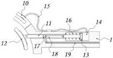
请参阅图1-7,本发明提供一种技术方案:一种心血管插管护理夹持器,包括第一夹持杆1和第二夹持杆2,第一夹持杆1和第二夹持杆2的中部之间为活动轴连接,且第一夹持杆1和第二夹持杆2的右端均开设有手指可以伸入的通孔;两个夹持弧3,其分别安装于第一夹持杆1和第二夹持杆2的左端,且两个夹持弧3构成一个圆环设置,可以套设在心血管插管的外侧;还包括有:固定座4,其固定安装于第一夹持杆1的上端,且固定座4右侧轴承安装有螺纹杆5,并且螺纹杆5的右端连接有转动块6,医护人员通过转动块6可以带动螺纹杆5进行转动;第一驱动杆7螺纹套设在螺纹杆5的外侧,且第一驱动杆7的横向截面长度小于第二驱动杆9横向截面长度;第一驱动杆7和第二驱动杆9,其分别贴合设置于第一夹持杆1和第二夹持杆2的内部,且第一驱动杆7和第二驱动杆9两者之间通过连接组件8实现连接;连接组件8由固定板801、H字形板802、连动块803和防脱块804组成,且固定板801位于第二驱动杆9的外侧,并且固定板801的前侧安装有H字形板802,而且H字形板802的侧部安装有四个连动块803,位于上方的两个连动块803贴合设置于第一驱动杆7的两侧内部,且位于下方的两个连动块803贴合设置于第二驱动杆9的两侧内部;结合图1-4所示,医护人员首先将手指分别伸入第一夹持杆1和第二夹持杆2右端所开设的通孔中,带动第一夹持杆1和第二夹持杆2进行相对转动,而后将插管置于两个夹持弧3之间,随后将在第二驱动杆9上推动连接组件8,促使连接组件8伸入第一驱动杆7的内部,实现第一驱动杆7和第二驱动杆9的连接,即实现第一夹持杆1和第二夹持杆2的连接,从而避免第一夹持杆1和第二夹持杆2受外力作用再次发生转动,故而可以避免医护人员出现手抖的情况导致插管出现掉落的情况,而后在固定座4上转动转动块6,带动所连接的螺纹杆5进行同步转动,当螺纹杆5转动后,套设在螺纹杆5外侧的第一驱动杆7在与第一夹持杆1的贴合作用下,可以实现向右移动,且利用连接组件8带动第二驱动杆9进行同步移动;第二驱动杆9的上端卡合滑动设置有两个截面呈梯形设置的防脱块804,且两个防脱块804分别安装于位于下方的两个连动块803的下部;结合图2-4所示,使得在防脱块804的作用下,可以避免连接组件8在第二驱动杆9上发生掉落或丢失的情况,延长使用寿命;1-7, the present invention provides a technical solution: a cardiovascular intubation nursing holder, comprising a first clamping rod 1 and a second clamping rod 2, a first clamping rod 1 and a second clamping rod The middle part of the clamping rod 2 is connected by a movable shaft, and the right ends of the first clamping rod 1 and the second clamping rod 2 are provided with through holes through which fingers can be inserted; the two clamping arcs 3 are respectively installed On the left ends of the first clamping rod 1 and the second clamping rod 2, and the two clamping arcs 3 form a circular ring arrangement, which can be sleeved on the outside of the cardiovascular cannula; also includes: a fixing seat 4, which is fixed It is installed on the upper end of the first clamping rod 1, and the right bearing of the fixed seat 4 is installed with a threaded rod 5, and the right end of the threaded rod 5 is connected with a rotating block 6, and the medical staff can drive the threaded rod 5 to rotate through the rotating block 6; The first driving rod 7 is threadedly sleeved on the outside of the threaded rod 5, and the transverse section length of the first driving rod 7 is smaller than the transverse section length of the second driving rod 9; the first driving rod 7 and the second driving rod 9 are respectively attached to It is arranged inside the first clamping rod 1 and the second clamping rod 2 together, and the connection between the first driving rod 7 and the second driving rod 9 is realized by the connecting assembly 8; The H-shaped plate 802, the interlocking block 803 and the anti-separation block 804 are composed, and the fixing plate 801 is located on the outer side of the second driving rod 9, and the front side of the fixing plate 801 is installed with the H-shaped plate 802, and the side of the H-shaped plate 802 There are four interlocking blocks 803 installed in the upper part, and the two interlocking blocks 803 located at the top are attached to the inside of both sides of the first driving rod 7, and the two interlocking blocks 803 located below are attached to the second driving rod 7. Inside the two sides of the
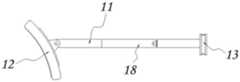
两个横杆11,其分别卡合滑动设置于第一夹持杆1和第二夹持杆2的内部,且横杆11的左右两端分别安装有定位板12和活塞板13;横杆11的左右两端与定位板12和活塞板13之间分别为活动轴连接和固定连接,且定位板12为弧形结构设置,并且定位板12的右侧安装有硅胶垫;横杆11的右侧外部套设有压力弹簧16,且压力弹簧16的右端固定在活塞板13的左侧,并且上下两个压力弹簧16的左端分别固定在第一夹持杆1和第二夹持杆2的内部;连通板17位于通槽18的内部,且通槽18贯通开设于横杆11的内部,并且上下两个横杆11通过连通板17分别与第一驱动杆7和第二驱动杆9之间连接有拉绳19;两个连通板17,其分别固定安装于第一夹持杆1和第二夹持杆2的内部;结合图1-2和图5-7所示,当第一驱动杆7和第二驱动杆9实现移动后,可以分别利用拉绳19带动相对应的横杆11进行移动,即带动定位板12和活塞板13同步移动,当定位板12移动后,可以实现对插管的固定限位作用,且当第一驱动杆7和第二驱动杆9实现反向移动时,横杆11可以利用压力弹簧16实现反向移动复位,以便再次使用;Two
活塞板13贴合位于空腔14的内壁,且空腔14分别开设于第一夹持杆1和第二夹持杆2的内部;空腔14的侧部与吸盘10之间通过软管15实现相互连通,且吸盘10安装于夹持弧3的内侧左部;结合图1和图5-6所示,使得当活塞板13在空腔14的内部发生移动后,可以促使空腔14形成负压,由于空腔14与吸盘10相互连通,故而吸盘10可以紧密贴合在插管的外侧,从而可以增强固定效果,保证心血管插管的顺利进行。The
工作原理:在使用该心血管插管护理夹持器时,结合图1-7所示,医护人员首先将手指分别伸入第一夹持杆1和第二夹持杆2右端所开设的通孔中,带动第一夹持杆1和第二夹持杆2进行相对转动,而后将插管置于两个夹持弧3之间,反向转动第一夹持杆1和第二夹持杆2,再将连接组件8推向第一驱动杆7的内部,再转动转动块6,利用连接组件8带动第一驱动杆7和第二驱动杆9进行同步移动,促使定位板12实现对插管的限位固定作用,且利用吸盘10增强固定效果,并且在连接组件8的作用下,可以避免第一夹持杆1和第二夹持杆2受外力发生转动,从而可以避免医护人员由于手抖导致插管出现掉落的情况,保证心血管插管的顺利进行。Working principle: When using the cardiovascular intubation nursing holder, as shown in Figures 1-7, the medical staff first put their fingers into the openings opened at the right ends of the
本说明书中未作详细描述的内容属于本领域专业技术人员公知的现有技术,在本发明的描述中,除非另有说明,“多个”的含义是两个或两个以上;术语“上”、“下”、“左”、“右”、“内”、“外”、“前端”、“后端”、“头部”、“尾部”等指示的方位或位置关系为基于附图所示的方位或位置关系,仅是为了便于描述本发明和简化描述,而不是指示或暗示所指的装置或元件必须具有特定的方位、以特定的方位构造和操作,因此不能理解为对本发明的限制。此外,术语“第一”、“第二”、“第三”等仅用于描述目的,而不能理解为指示或暗示相对重要性。在本发明的描述中,需要说明的是,除非另有明确的规定和限定,术语“相连”、“连接”应做广义理解,例如,可以是固定连接,也可以是可拆卸连接,或一体地连接;可以是机械连接,也可以是电连接;可以是直接相连,也可以通过中间媒介间接相连。对于本领域的普通技术人员而言,可以具体情况理解上述术语在本发明中的具体含义。The content not described in detail in this specification belongs to the prior art known to those skilled in the art. In the description of the present invention, unless otherwise specified, the meaning of "plurality" means two or more; the term "above" "," "down", "left", "right", "inside", "outside", "front end", "rear end", "head", "tail" etc. The orientation or positional relationship indicated is based on the drawings The orientation or positional relationship shown is only for the convenience of describing the present invention and simplifying the description, rather than indicating or implying that the indicated device or element must have a specific orientation, be constructed and operated in a specific orientation, and therefore should not be construed as a reference to the present invention. limits. Furthermore, the terms "first," "second," "third," etc. are used for descriptive purposes only and should not be construed to indicate or imply relative importance. In the description of the present invention, it should be noted that, unless otherwise expressly specified and limited, the terms "connected" and "connected" should be understood in a broad sense, for example, it may be a fixed connection, a detachable connection, or an integral connection. Ground connection; it can be a mechanical connection or an electrical connection; it can be directly connected or indirectly connected through an intermediate medium. For those of ordinary skill in the art, the specific meanings of the above terms in the present invention can be understood in specific situations.
尽管参照前述实施例对本发明进行了详细的说明,对于本领域的技术人员来说,其依然可以对前述各实施例所记载的技术方案进行修改,或者对其中部分技术特征进行等同替换,凡在本发明的精神和原则之内,所作的任何修改、等同替换、改进等,均应包含在本发明的保护范围之内。Although the present invention has been described in detail with reference to the foregoing embodiments, for those skilled in the art, it is still possible to modify the technical solutions described in the foregoing embodiments, or to perform equivalent replacements for some of the technical features. Any modification, equivalent replacement, improvement, etc. made within the spirit and principle of the present invention shall be included within the protection scope of the present invention.
Claims (9)
Translated fromChinesePriority Applications (1)
| Application Number | Priority Date | Filing Date | Title |
|---|---|---|---|
| CN202210730198.3ACN115192133B (en) | 2022-06-24 | 2022-06-24 | Cardiovascular intubate nursing holder |
Applications Claiming Priority (1)
| Application Number | Priority Date | Filing Date | Title |
|---|---|---|---|
| CN202210730198.3ACN115192133B (en) | 2022-06-24 | 2022-06-24 | Cardiovascular intubate nursing holder |
Publications (2)
| Publication Number | Publication Date |
|---|---|
| CN115192133Atrue CN115192133A (en) | 2022-10-18 |
| CN115192133B CN115192133B (en) | 2025-08-01 |
Family
ID=83577973
Family Applications (1)
| Application Number | Title | Priority Date | Filing Date |
|---|---|---|---|
| CN202210730198.3AActiveCN115192133B (en) | 2022-06-24 | 2022-06-24 | Cardiovascular intubate nursing holder |
Country Status (1)
| Country | Link |
|---|---|
| CN (1) | CN115192133B (en) |
Citations (9)
| Publication number | Priority date | Publication date | Assignee | Title |
|---|---|---|---|---|
| US20020058856A1 (en)* | 1999-09-07 | 2002-05-16 | Origin Medsystems, Inc. | Locking arm having ball joints for use in an organ manipulator apparatus |
| US20140107697A1 (en)* | 2012-06-25 | 2014-04-17 | Castle Surgical, Inc. | Clamping Forceps and Associated Methods |
| CN108938063A (en)* | 2018-07-26 | 2018-12-07 | 侯玉莹 | A kind of urgent midwifery intelligent apparatus of obstetrics and gynecology department |
| CN208725828U (en)* | 2018-05-07 | 2019-04-12 | 顾冰 | A kind of cardio-vascular clinical operation accessory part |
| CN211301676U (en)* | 2019-12-23 | 2020-08-21 | 任超 | Novel cardiovascular intubation tube clamp holder |
| US20210069870A1 (en)* | 2017-09-01 | 2021-03-11 | Daewon Electric Co.,Ltd. | Manual hydraulic multi-functional extra-high-voltage insulating gear gripper pliers stick for live-wire work and indirect live-wire construction method using pliers stick |
| CN213640988U (en)* | 2020-07-27 | 2021-07-09 | 昆明医科大学第二附属医院 | Special peritoneoscope area nipper aspirator of hepatobiliary surgery |
| CN114129855A (en)* | 2021-12-04 | 2022-03-04 | 南阳南石医院 | Interactive visual catheter approach assisting mirror and urethral catheterization device |
| CN216294963U (en)* | 2021-11-15 | 2022-04-15 | 宏葵生物(中国)股份有限公司 | Novel cardiovascular intubation tube clamp holder |
- 2022
- 2022-06-24CNCN202210730198.3Apatent/CN115192133B/enactiveActive
Patent Citations (9)
| Publication number | Priority date | Publication date | Assignee | Title |
|---|---|---|---|---|
| US20020058856A1 (en)* | 1999-09-07 | 2002-05-16 | Origin Medsystems, Inc. | Locking arm having ball joints for use in an organ manipulator apparatus |
| US20140107697A1 (en)* | 2012-06-25 | 2014-04-17 | Castle Surgical, Inc. | Clamping Forceps and Associated Methods |
| US20210069870A1 (en)* | 2017-09-01 | 2021-03-11 | Daewon Electric Co.,Ltd. | Manual hydraulic multi-functional extra-high-voltage insulating gear gripper pliers stick for live-wire work and indirect live-wire construction method using pliers stick |
| CN208725828U (en)* | 2018-05-07 | 2019-04-12 | 顾冰 | A kind of cardio-vascular clinical operation accessory part |
| CN108938063A (en)* | 2018-07-26 | 2018-12-07 | 侯玉莹 | A kind of urgent midwifery intelligent apparatus of obstetrics and gynecology department |
| CN211301676U (en)* | 2019-12-23 | 2020-08-21 | 任超 | Novel cardiovascular intubation tube clamp holder |
| CN213640988U (en)* | 2020-07-27 | 2021-07-09 | 昆明医科大学第二附属医院 | Special peritoneoscope area nipper aspirator of hepatobiliary surgery |
| CN216294963U (en)* | 2021-11-15 | 2022-04-15 | 宏葵生物(中国)股份有限公司 | Novel cardiovascular intubation tube clamp holder |
| CN114129855A (en)* | 2021-12-04 | 2022-03-04 | 南阳南石医院 | Interactive visual catheter approach assisting mirror and urethral catheterization device |
Also Published As
| Publication number | Publication date |
|---|---|
| CN115192133B (en) | 2025-08-01 |
Similar Documents
| Publication | Publication Date | Title |
|---|---|---|
| CN209826647U (en) | Medical mouth gag for department of stomatology | |
| CN115192133A (en) | A Cardiovascular Intubation Nursing Holder | |
| CN219021114U (en) | A kind of multifunctional dental mirror | |
| CN110664502A (en) | Oral cavity restoration clinical treatment auxiliary device | |
| CN207785615U (en) | A pediatric emergency oxygen-increased respirator | |
| CN215585119U (en) | Severe nursing breathing machine is with scalable ponding respiratory tube of preventing | |
| CN211433789U (en) | Medical bed | |
| CN115500971A (en) | Oral implant registration and fixing device | |
| CN211560767U (en) | Head fixing auxiliary device | |
| CN217246013U (en) | Oxygen inhalation device for neonates | |
| CN214157503U (en) | Connector protection architecture of epidural catheter | |
| CN220158996U (en) | A negative pressure suction tube fixation device | |
| CN214970990U (en) | Special syringe type negative pressure drainage device for tiny wound surface | |
| CN214596339U (en) | Cardiovascular intervention nursing tray | |
| CN221636134U (en) | Fixing frame for denture processing | |
| CN220192979U (en) | Stomatoscope structure with angle adjusting structure | |
| CN217042703U (en) | Test tube for medical examination | |
| CN219814333U (en) | Clinical clamping device | |
| CN221180382U (en) | Novel adjustable digestion scope support | |
| CN219662532U (en) | Simple respirator convenient to use | |
| CN214285461U (en) | Auxiliary device for patient of CT machine | |
| CN108451603A (en) | A kind of Ultrasound Instrument having ultrasonic puncture navigation | |
| CN213047206U (en) | Foreign matter pincers for gastroenterology | |
| CN219630556U (en) | Respiratory training device capable of being flexibly adjusted in respiratory department | |
| CN210277114U (en) | Examination device for department of respiration |
Legal Events
| Date | Code | Title | Description |
|---|---|---|---|
| PB01 | Publication | ||
| PB01 | Publication | ||
| SE01 | Entry into force of request for substantive examination | ||
| SE01 | Entry into force of request for substantive examination | ||
| GR01 | Patent grant | ||
| GR01 | Patent grant |