CN115192126A - Quick-release type suction device - Google Patents
Quick-release type suction deviceDownload PDFInfo
- Publication number
- CN115192126A CN115192126ACN202210892896.3ACN202210892896ACN115192126ACN 115192126 ACN115192126 ACN 115192126ACN 202210892896 ACN202210892896 ACN 202210892896ACN 115192126 ACN115192126 ACN 115192126A
- Authority
- CN
- China
- Prior art keywords
- quick
- suction device
- connecting pipe
- release joint
- rear end
- Prior art date
- Legal status (The legal status is an assumption and is not a legal conclusion. Google has not performed a legal analysis and makes no representation as to the accuracy of the status listed.)
- Pending
Links
Images


Classifications
- A—HUMAN NECESSITIES
- A61—MEDICAL OR VETERINARY SCIENCE; HYGIENE
- A61B—DIAGNOSIS; SURGERY; IDENTIFICATION
- A61B17/00—Surgical instruments, devices or methods
- A61B17/22—Implements for squeezing-off ulcers or the like on inner organs of the body; Implements for scraping-out cavities of body organs, e.g. bones; for invasive removal or destruction of calculus using mechanical vibrations; for removing obstructions in blood vessels, not otherwise provided for
- A61B2017/22001—Angioplasty, e.g. PCTA
- A—HUMAN NECESSITIES
- A61—MEDICAL OR VETERINARY SCIENCE; HYGIENE
- A61B—DIAGNOSIS; SURGERY; IDENTIFICATION
- A61B17/00—Surgical instruments, devices or methods
- A61B17/22—Implements for squeezing-off ulcers or the like on inner organs of the body; Implements for scraping-out cavities of body organs, e.g. bones; for invasive removal or destruction of calculus using mechanical vibrations; for removing obstructions in blood vessels, not otherwise provided for
- A61B2017/22079—Implements for squeezing-off ulcers or the like on inner organs of the body; Implements for scraping-out cavities of body organs, e.g. bones; for invasive removal or destruction of calculus using mechanical vibrations; for removing obstructions in blood vessels, not otherwise provided for with suction of debris
Landscapes
- Health & Medical Sciences (AREA)
- Surgery (AREA)
- Life Sciences & Earth Sciences (AREA)
- Heart & Thoracic Surgery (AREA)
- Nuclear Medicine, Radiotherapy & Molecular Imaging (AREA)
- Vascular Medicine (AREA)
- Engineering & Computer Science (AREA)
- Biomedical Technology (AREA)
- Orthopedic Medicine & Surgery (AREA)
- Medical Informatics (AREA)
- Molecular Biology (AREA)
- Animal Behavior & Ethology (AREA)
- General Health & Medical Sciences (AREA)
- Public Health (AREA)
- Veterinary Medicine (AREA)
- External Artificial Organs (AREA)
Abstract
Translated fromChinese
Description
Translated fromChinese技术领域technical field
本发明涉及一种快拆式抽吸装置,属于血栓清除医疗器械技术领域。The invention relates to a quick-release suction device, which belongs to the technical field of thrombus removal medical devices.
背景技术Background technique
随着人们生活水平的提高,血栓性疾病发病率日益增长,血栓能够阻碍或完全中断血液流动,若栓塞发生在心脑血管中将会造成严重后果,轻则致残,严重可导致死亡,影响生命健康,如何快速有效的消除栓塞是目前本领域技术人员亟待解决的问题。With the improvement of people's living standards, the incidence of thrombotic diseases is increasing day by day. Blood clots can hinder or completely interrupt blood flow. If the embolism occurs in the cardiovascular and cerebrovascular vessels, it will cause serious consequences, ranging from disability to serious death. Life is healthy, and how to quickly and effectively eliminate embolism is an urgent problem to be solved by those skilled in the art.
现有临床手术过程中,通常使用传统的一次性医用注射器连同取栓导管将阻塞血管的血栓等异物抽吸至体外,重新恢复血运循环。In the existing clinical operation, a traditional disposable medical syringe and a thrombectomy catheter are usually used to aspirate foreign bodies such as thrombus blocking the blood vessel out of the body to restore blood circulation.
但是,目前临床上使用的一次性注射器的主要应用范围和功能,是为了向体内注射液体,并没有针对血栓抽吸等特殊的临床应用场景进行专用设计,在抽吸血栓时有诸多操作不便之处:(1)现有的注射器与取栓导管采用鲁尔结构,需要旋转数圈才能完成器械间的分离,重复进行血栓抽吸时,需要多次分离,抽吸效率交底,操作繁琐;(2)注射器提供负压时,需要医生双手操作,一手握住注射器外套管,另一手拉住芯杆,不能自动维持内压;(3)注射器的芯杆把手的形状通常设计为便于推送,在抽吸血栓时需要回撤芯杆形成负压,拉拔时医生使用不方便;(4)注射器从抽吸导管后撤分离时,会形成活塞效应,血液会随着注射器后撤时流出,导致病人出血过多。However, the main application scope and functions of the disposable syringes currently used clinically are to inject liquid into the body, and there is no special design for special clinical application scenarios such as thrombus aspiration. (1) The existing syringe and thrombectomy catheter use a Luer structure, which requires several rotations to complete the separation between the instruments. When repeated thrombus suction, multiple separations are required, the suction efficiency is revealed, and the operation is cumbersome; ( 2) When the syringe provides negative pressure, the doctor needs to operate with both hands, holding the outer sleeve of the syringe with one hand, and pulling the core rod with the other hand, and the internal pressure cannot be automatically maintained; (3) The shape of the handle of the core rod of the syringe is usually designed to facilitate pushing, and the When sucking the thrombus, it is necessary to withdraw the core rod to form a negative pressure, which is inconvenient for doctors to use when pulling; (4) When the syringe is withdrawn and separated from the suction catheter, a piston effect will be formed, and the blood will flow out when the syringe is withdrawn, resulting in The patient is bleeding excessively.
现有技术公开了一种负压注射器(公开号:CN213249512U),它通过在针筒和活塞杆上分别设置锁定结构,从而可在抽拉到位时,通过锁定结构将活塞杆锁定在针筒上进行抽吸,由此不仅可便于医生单手完成部分抽吸操作,操作过程更省力,而且可更准确地控制抽吸负压,达到更佳的治疗效果。但是,注射器(相当于抽吸器)在完成一次抽吸后,需要将取栓导管和抽吸器分离,以便排出抽吸器中的血栓后,进行重复抽吸。现有的抽吸器与取栓导管之间的连接结构,不能快速插拔,并且在拔出抽吸器时,容易导致血液外溢,甚至引起虹吸现象,导致大量血液流失。The prior art discloses a negative pressure syringe (publication number: CN213249512U), which can lock the piston rod on the syringe through the locking structure when the syringe barrel and the piston rod are respectively provided with locking structures when it is drawn in place By performing suction, it is not only convenient for the doctor to complete part of the suction operation with one hand, and the operation process is more labor-saving, but also the suction negative pressure can be controlled more accurately, so as to achieve a better therapeutic effect. However, after a syringe (equivalent to aspirator) completes one suction, it is necessary to separate the thrombectomy catheter from the aspirator, so as to discharge the thrombus in the aspirator and perform repeated suction. The existing connection structure between the aspirator and the thrombectomy catheter cannot be quickly inserted and pulled out, and when the aspirator is pulled out, it is easy to cause blood spillage or even a siphon phenomenon, resulting in a large amount of blood loss.
针对以上临床需求,设计出一种快拆式抽吸装置,它具有快拆接头,可快速与取栓导管的通路连接和分离,并通过设置气孔,防止血液外流;抽吸装置芯杆把手形状更适合回撤操作;抽吸装置带有多级限位结构,可满足临床不同程度负压需求;同时配有开关阀,可实现持续的低负压满足细小血管的抽吸需求。In view of the above clinical needs, a quick-release suction device is designed. It has a quick-release joint, which can be quickly connected and separated from the passage of the thrombectomy catheter, and the air hole is provided to prevent blood from flowing out; the shape of the handle of the core rod of the suction device It is more suitable for retraction operation; the suction device has a multi-stage limit structure, which can meet the needs of different levels of clinical negative pressure; at the same time, it is equipped with an on-off valve, which can achieve continuous low negative pressure to meet the suction needs of small blood vessels.
发明内容SUMMARY OF THE INVENTION
本发明所要解决的技术问题在于:提供一种快拆式抽吸装置,它解决了目前临床上使用一次性注射器来抽吸血栓,无法快速分离,导致吸栓效率较低的问题。The technical problem to be solved by the present invention is: to provide a quick-release suction device, which solves the problem that the current clinical use of disposable syringes to suction thrombus cannot be quickly separated, resulting in low thrombus suction efficiency.
本发明所要解决的技术问题采取以下技术方案来实现:The technical problem to be solved by this invention adopts the following technical solutions to realize:
一种快拆式抽吸装置,它包括抽吸器,以及与抽吸器连接的取栓导管,取栓导管上设有开关阀,所述抽吸器包括外套管、芯杆、限位塞、活塞密封圈;A quick-release suction device, which includes a suction device, and a thrombus removal catheter connected with the aspirator, an on-off valve is arranged on the bolt removal catheter, and the aspirator includes an outer casing, a core rod, and a limit plug , piston sealing ring;
所述抽吸器的外套管前端设置连接管,取栓导管通过快拆接头与连接管密封连接;The front end of the outer sleeve of the aspirator is provided with a connecting pipe, and the bolus removal catheter is sealedly connected with the connecting pipe through a quick-release joint;
所述快拆接头后端设有插槽,插槽侧壁设有气孔,连接管前端完全密封插入快拆接头插槽时,气孔被连接管侧面封闭。The rear end of the quick release joint is provided with a slot, and the side wall of the slot is provided with an air hole. When the front end of the connection pipe is completely sealed and inserted into the quick release joint slot, the air hole is closed by the side of the connection pipe.
作为优选实例,所述外套管前端与取栓导管密封连接,外套管的后端设置芯杆插入的开口,外套管靠近后端的侧面设有插入内腔的限位塞;As a preferred example, the front end of the outer sleeve is sealedly connected to the stud removal catheter, the rear end of the outer sleeve is provided with an opening into which the core rod is inserted, and the side of the outer sleeve close to the rear end is provided with a limit plug inserted into the lumen;
所述芯杆从外套管的后端开口插入内部,芯杆前端设有与外套管内壁密封的活塞密封圈,芯杆设有沿轴线方向的滑槽,滑槽上设有多个侧孔,每个侧孔内后端设有横向挡板,限位塞位于滑槽内,当限位塞与侧孔对齐时,转动芯杆使得侧孔内的横向挡板抵靠在限位塞上。The core rod is inserted into the interior from the rear end opening of the outer casing, the front end of the core rod is provided with a piston sealing ring that seals with the inner wall of the outer casing, the core rod is provided with a chute along the axis direction, and the chute is provided with a plurality of side holes, The inner rear end of each side hole is provided with a transverse baffle, and the limit plug is located in the chute. When the limit plug is aligned with the side hole, the core rod is rotated so that the transverse baffle in the side hole abuts on the limit plug.
通过在芯杆上设置带侧孔的滑槽,形成负压锁定和保持机构,侧孔内设置横向挡板,芯杆拉拔后形成负压,当限位塞与侧孔对齐时,能够通过转动芯杆,使得侧孔内的横向挡板转动后抵靠在限位塞上,此时旋转芯杆不会被负压拉回,不需要医生一直维持抽吸器的拉拔状态,相对于现有的针管更加省力和方便。A negative pressure locking and holding mechanism is formed by setting a chute with a side hole on the core rod. A transverse baffle is set in the side hole, and a negative pressure is formed after the core rod is drawn. When the limit plug is aligned with the side hole, it can pass through Rotate the core rod, so that the lateral baffle in the side hole is rotated and rests on the limit plug. At this time, the rotating core rod will not be pulled back by the negative pressure, and the doctor does not need to maintain the pulling state of the aspirator all the time. The existing needle tube is more labor-saving and convenient.
作为优选实例,所述外套管前端设置连接管,取栓导管通过快拆接头与连接管密封连接。抽吸器的连接管能够根据需要设置内径,不必受到一次性注射器国家标准限制,连接管直径可以超过3mm,优选5mm及以上,能够防止最窄处的连接管处阻塞。As a preferred example, the front end of the outer sleeve is provided with a connecting pipe, and the spigot removal catheter is sealedly connected to the connecting pipe through a quick release joint. The inner diameter of the connecting tube of the aspirator can be set as required, and it does not need to be restricted by the national standard for disposable syringes. The diameter of the connecting tube can exceed 3mm, preferably 5mm or more, which can prevent the narrowest connecting tube from being blocked.
所述连接管从前端到后端依次设有头端密封圈和一圈凸起的圆台,快拆接头前端与取栓导管密封连接,快拆接头后端沿圆周均匀设置有至少2个弹性扣爪,将连接管前端完全插入快拆接头的后端,弹性扣爪卡接在圆台处,连接管通过头端密封圈与快拆接头密封。The connecting pipe is sequentially provided with a head end sealing ring and a raised circular platform from the front end to the rear end, the front end of the quick release joint is sealedly connected with the bolt removal catheter, and the rear end of the quick release joint is evenly arranged with at least 2 elastic buckles along the circumference. The front end of the connecting pipe is completely inserted into the rear end of the quick release joint, the elastic claw is clamped at the round table, and the connecting pipe is sealed with the quick release joint through the head end sealing ring.
所述连接管前端完全插入快拆接头时,气孔位于头端密封圈之后。When the front end of the connecting pipe is completely inserted into the quick release joint, the air hole is located behind the sealing ring of the head end.
所述快拆接头的弹性扣爪由支撑部、压板部、爪头构成,压板部侧面通过支撑部与快拆接头侧面连接,压板部后端设有向内弯折的爪头,当连接管前端完全插入快拆接头的后端时,爪头卡接在圆台处。The elastic claw of the quick release joint is composed of a support part, a pressure plate part and a claw head. The side surface of the pressure plate part is connected with the side surface of the quick release joint through the support part. When the front end is completely inserted into the rear end of the quick release joint, the claw head is clamped at the round table.
采用快拆接头能够更加方便的进行组装和拆卸,方便医生使用。The quick-release joint can be assembled and disassembled more conveniently, which is convenient for doctors to use.
作为优选实例,所述芯杆后端设有T形夹持部,T形夹持部前端面手指位置设有用于拉拔的食指弧形槽和中指弧形槽,T形夹持部后端面手指位置设有用于推压的大拇指弧形槽。As a preferred example, the rear end of the core rod is provided with a T-shaped clamping portion, the finger position of the front end surface of the T-shaped clamping portion is provided with an index finger arc groove and a middle finger arc groove for drawing, and the rear end surface of the T-shaped clamping portion is provided with an arc groove for the index finger and the middle finger. There are thumb arc grooves for pushing in the finger position.
手指接触的地方设置弧形槽,能够更加贴合手指,提高舒适性。Arc-shaped grooves are set where the fingers touch, which can better fit the fingers and improve comfort.
作为优选实例,所述芯杆前端设有环形槽,环形槽内固定有活塞密封圈。As a preferred example, the front end of the core rod is provided with an annular groove, and a piston sealing ring is fixed in the annular groove.
使用环形槽固定活塞密封圈,当活塞密封圈长时间使用受损后,能够方便更换。The annular groove is used to fix the piston sealing ring, which can be easily replaced when the piston sealing ring is damaged after long-term use.
本发明的有益效果是:The beneficial effects of the present invention are:
(1)取栓导管和抽吸器之间通过快拆接头连接,抽吸器可快速与取栓导管的通路快速连接和分离,同时保证连接处的高负压密封性;(1) The thrombectomy catheter and the aspirator are connected by a quick-release joint, and the aspirator can be quickly connected and separated from the passage of the thrombectomy catheter, while ensuring the high negative pressure sealing at the connection;
(2)快拆接头设置气孔,抽吸器拆卸过程中,当头端密封圈越过快拆接头的气孔时,抽吸腔道内的压力减小,血液不再随抽吸器的拔出而外溢,防止病人失血过多;(2) The quick release joint is provided with an air hole. During the disassembly process of the aspirator, when the head end sealing ring passes over the air hole of the quick release joint, the pressure in the suction cavity is reduced, and the blood no longer overflows with the extraction of the aspirator. Prevent the patient from losing too much blood;
(3)抽吸器的芯杆带有多个侧孔和横向挡板,形成多档位负压锁定和保持机构,可满足临床不同程度和不同容量的负压抽吸需求,同时产生无外力维持的、稳定的蓄积负压真空能。(3) The core rod of the aspirator has multiple side holes and transverse baffles to form a multi-position negative pressure locking and holding mechanism, which can meet the needs of clinical negative pressure suction of different degrees and volumes, while generating no external force. Maintained and stable accumulation of negative pressure vacuum energy.
附图说明Description of drawings
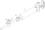
图1为本发明的结构示意图;Fig. 1 is the structural representation of the present invention;
图2为芯杆的结构示意图;Fig. 2 is the structural representation of core rod;
图3为抽吸器的结构示意图;Fig. 3 is the structural representation of aspirator;
图4为快拆接头的结构示意图;Fig. 4 is the structural representation of quick release joint;
图5为快拆接头与抽吸器的连接结构示意图。FIG. 5 is a schematic diagram of the connection structure of the quick release joint and the aspirator.
图中:1、抽吸器;101、外套管;102、芯杆;103、限位塞;104、活塞密封圈;105、滑槽;106、侧孔;107、横向挡板;108、连接管;109、头端密封圈;110、圆台;111、T形夹持部;1111、食指弧形槽;1112、中指弧形槽;1113、大拇指弧形槽;112、环形槽;2、取栓导管;3、开关阀;4、快拆接头;401、弹性扣爪;4011、支撑部;4012、压板部;4013、爪头;402、插槽;403、气孔;404、过盈配合接头。In the figure: 1, aspirator; 101, outer casing; 102, core rod; 103, limit plug; 104, piston sealing ring; 105, chute; 106, side hole; 107, transverse baffle; 108, connection Tube; 109, head end sealing ring; 110, round table; 111, T-shaped clamping part; 1111, index finger arc groove; 1112, middle finger arc groove; 1113, thumb arc groove; 112, annular groove; 2, Bolt removal catheter; 3. On-off valve; 4. Quick release joint; 401, elastic claw; 4011, support part; 4012, pressure plate part; 4013, claw head; 402, slot; 403, air hole; 404, interference fit connector.
具体实施方式Detailed ways
为了对本发明的技术手段、创作特征、达成目的与功效易于明白了解,下面结合具体实施例,进一步阐述本发明。In order to easily understand the technical means, creation features, achievement goals and effects of the present invention, the present invention will be further described below with reference to specific embodiments.
本文所述的“前端”、“远端”表示靠近血管的一端,“后端”、“近端”表示靠近操作医生的一端。As used herein, "front end" and "distal end" refer to the end close to the blood vessel, and "back end" and "proximal end" refer to the end close to the operating physician.
实施例1Example 1
如图1-图5所示,本抽吸装置包括抽吸器1,以及与抽吸器1连接的取栓导管2,抽吸器1包括外套管101、芯杆102、限位塞103、活塞密封圈104。As shown in Figures 1-5, the suction device includes a suction device 1 and a thrombus removal catheter 2 connected to the suction device 1. The suction device 1 includes an
抽吸器1的外套管101前端设置连接管108,取栓导管2通过快拆接头4与连接管108密封连接;The front end of the
所述快拆接头4后端设有插槽402,插槽402侧壁设有气孔403,插槽402粗于快拆接头4主体,形成台阶式内孔,连接管108前端完全密封插入快拆接头4插槽402(连接管108前端抵靠在台阶处)时,气孔403被连接管108侧面封闭。The rear end of the quick release joint 4 is provided with a
如图4-图5所示,快拆接头4的后端侧面设有气孔403,连接管108前端完全插入快拆接头4时,气孔403位于头端密封圈109之后。As shown in FIGS. 4-5 , the rear end side of the quick release joint 4 is provided with an
将取栓导管2的快拆接头4从外套管101的连接管108上拔下,当连接管108的头端密封圈109越过快拆接头4的气孔403时,抽吸腔道内的压力减小,血液不再随抽吸器1的拔出而外溢,防止病人失血过多。Pull out the
外套管101前端与取栓导管2密封连接,外套管101的后端设置芯杆102插入的开口,外套管101靠近后端的侧面设有插入内腔的限位塞103,限位塞103通过卡接、螺接、过盈配合等方式固定在外套管101侧面,限位塞103可以方便的拆卸,以便安装和拆卸芯杆102;The front end of the
芯杆102从外套管101的后端开口插入内部,芯杆102前端设有与外套管101内壁密封的活塞密封圈104,芯杆102设有沿轴线方向的滑槽105,滑槽105上设有多个侧孔106,每个侧孔106内后端设有横向挡板107,限位塞103位于滑槽105内,当限位塞103与侧孔106对齐时,转动芯杆102使得侧孔106内的横向挡板107抵靠在限位塞103上。The
通过在芯杆102上设置带侧孔106的滑槽105,侧孔106内设置横向挡板107,芯杆102拉拔后形成负压,当限位塞103与侧孔106对齐时,能够通过转动芯杆102,使得侧孔106内的横向挡板107转动后抵靠在限位塞103上,此时旋转芯杆102不会被负压拉回,不需要医生一直维持抽吸器1的拉拔状态,相对于现有的针管更加省力和方便。By setting the
实施例2Example 2
如图3-图5所示,外套管101前端设置连接管108,取栓导管2通过快拆接头4与连接管108密封连接。抽吸器1的连接管108能够根据需要设置内径,不必受到一次性注射器国家标准限制,连接管108直径可以超过3mm。As shown in FIGS. 3-5 , the front end of the
连接管108从前端到后端依次设有头端密封圈109和一圈凸起的圆台110,快拆接头4前端与取栓导管2密封连接,快拆接头4后端沿圆周均匀设置有至少2个弹性扣爪401,将连接管108前端完全插入快拆接头4的后端,弹性扣爪401卡接在圆台110处,连接管108通过头端密封圈109与快拆接头4密封。The connecting
快拆接头4的弹性扣爪401由支撑部4011、压板部4012、爪头4013构成,压板部4012侧面通过支撑部4011与快拆接头4侧面连接,压板部4012后端设有向内弯折的爪头4013,当连接管108前端完全插入快拆接头4的后端时,爪头4013卡接在圆台110处。The
采用快拆接头4能够更加方便的进行组装和拆卸,方便医生使用。The quick-
实施例3Example 3
如图3所示,芯杆102后端设有T形夹持部111,T形夹持部111前端面手指位置设有用于拉拔的食指弧形槽1111和中指弧形槽1112,T形夹持部111后端面手指位置设有用于推压的大拇指弧形槽1113。As shown in FIG. 3 , the rear end of the
手指接触的地方设置弧形槽,能够更加贴合手指,提高舒适性。Arc-shaped grooves are set where the fingers touch, which can better fit the fingers and improve comfort.
实施例4Example 4
如图2、图3所示,芯杆102前端设有环形槽112,环形槽112内固定有活塞密封圈104。As shown in FIGS. 2 and 3 , the front end of the
使用环形槽112固定活塞密封圈104,当活塞密封圈104长时间使用受损后,能够方便更换。The
实施例5Example 5
取栓导管2上设有开关阀3。An on-off
开关阀3可以控制取栓导管2由完全导通逐渐切换至完全关闭状态。在对小血管取栓时(此时,大抽吸量会导致细小血管闭塞),通过开关阀3将取栓导管2切换至更小抽吸量的状态,以此实现持续的低负压,满足细小血管的抽吸需求。The on-off
使用方法:Instructions:
在生产取栓导管2时,将快拆接头4前端与取栓导管2的后端密封固定(快拆接头4前端设置过盈配合接头404,过盈配合接头404是由端部到中部逐渐变粗的锥形管,锥形管大头端直径大于快拆接头4前端管径,取栓导管2通过热胀方式套在过盈配合接头404上冷却后能够达到较好的密封连接效果,此外,为了进一步提高连接处的强度,还可以采用过盈配合+胶水固化的双重连接方式配合使用),快拆接头4与取栓导管2的内腔联通。When producing the bolus removal catheter 2, the front end of the quick release joint 4 is sealed and fixed with the rear end of the bolster removal catheter 2 (the front end of the quick release joint 4 is provided with an interference fit joint 404, and the interference fit joint 404 gradually changes from the end to the middle. Thick conical tube, the diameter of the large end of the conical tube is larger than the diameter of the front end of the quick-
(1)当取栓导管2置入人体血管且取栓导管2的远端到达血栓附近时,将抽吸器1与快拆接头4对插到底,确认快拆接头4的扣爪已扣住外套管101连接管108上的圆台110,手指夹在芯杆102的T形夹持部111上,弯曲手指拉拔芯杆102,根据预期需要的负压回撤芯杆102,使相应压力位置的侧孔106和横向挡板107与限位塞103平齐,旋转芯杆102使限位塞103旋入侧孔106中卡在横向挡板107处,此时医生松开芯杆102,无需外力,抽吸器1内依然维持一定的负压。(1) When the thrombectomy catheter 2 is placed in the human blood vessel and the distal end of the thrombectomy catheter 2 reaches the vicinity of the thrombus, insert the aspirator 1 and the quick release joint 4 to the bottom, and confirm that the claws of the quick release joint 4 have been buckled The
(2)快速打开开关阀3,负压传导至取栓导管2的远端,将附近的血栓吸出人体。(2) Quickly open the on-off
(3)关闭开关阀3,按压快拆接头4的扣爪,并将取栓导管2的快拆接头4从外套管101的连接管108上拔下,当连接管108的头端密封圈109越过快拆接头4的气孔403时,抽吸腔道内的压力减小,血液不再随抽吸器1的拔出而外溢。(3) Close the
(4)旋转芯杆102,使得限位塞103回到滑槽105内,并推送芯杆102将血栓排出抽吸器1。(4) Rotate the
(5)重复以上过程,即可实现临床重复式抽吸过程。(5) Repeat the above process to realize the clinical repeated suction process.
抽吸器1与快拆接头4再次对接前,需要将空气从抽吸器1内部完全排出,减少抽吸腔道内的空气含量,降低空气进入人体的风险。Before the aspirator 1 and the quick release joint 4 are docked again, the air needs to be completely discharged from the inside of the aspirator 1 to reduce the air content in the suction cavity and reduce the risk of air entering the human body.
以上显示和描述了本发明的基本原理、主要特征和优点。本领域的技术人员应该了解,本发明不受上述实施例的限制,在不脱离本发明精神和范围的前提下,本发明还会有各种变化和改进,这些变化和改进都落入本发明要求保护的范围内。本发明要求保护范围由所附的权利要求书及其等效物界定。The foregoing has shown and described the basic principles, main features and advantages of the present invention. Those skilled in the art should understand that the present invention is not limited by the above-mentioned embodiments, and without departing from the spirit and scope of the present invention, the present invention will also have various changes and improvements, and these changes and improvements all fall into the present invention within the scope of protection. The claimed scope of the present invention is defined by the appended claims and their equivalents.
Claims (8)
Translated fromChinesePriority Applications (1)
| Application Number | Priority Date | Filing Date | Title |
|---|---|---|---|
| CN202210892896.3ACN115192126A (en) | 2022-07-27 | 2022-07-27 | Quick-release type suction device |
Applications Claiming Priority (1)
| Application Number | Priority Date | Filing Date | Title |
|---|---|---|---|
| CN202210892896.3ACN115192126A (en) | 2022-07-27 | 2022-07-27 | Quick-release type suction device |
Publications (1)
| Publication Number | Publication Date |
|---|---|
| CN115192126Atrue CN115192126A (en) | 2022-10-18 |
Family
ID=83584641
Family Applications (1)
| Application Number | Title | Priority Date | Filing Date |
|---|---|---|---|
| CN202210892896.3APendingCN115192126A (en) | 2022-07-27 | 2022-07-27 | Quick-release type suction device |
Country Status (1)
| Country | Link |
|---|---|
| CN (1) | CN115192126A (en) |
Cited By (1)
| Publication number | Priority date | Publication date | Assignee | Title |
|---|---|---|---|---|
| CN117426835A (en)* | 2023-12-20 | 2024-01-23 | 江西钶维肽生物科技有限公司 | Thrombus extraction assembly |
Citations (11)
| Publication number | Priority date | Publication date | Assignee | Title |
|---|---|---|---|---|
| US5114400A (en)* | 1990-06-19 | 1992-05-19 | Lynn Lawrence A | Blood withdrawal apparatus and method |
| US5401255A (en)* | 1993-07-20 | 1995-03-28 | Baxter International Inc. | Multi-functional valve with unitary valving member and improved safety |
| CN102335464A (en)* | 2010-07-27 | 2012-02-01 | 上海理工大学 | Injection and suction pump for removing thrombus |
| US20140296868A1 (en)* | 2013-03-29 | 2014-10-02 | Silk Road Medical, Inc. | Systems and methods for aspirating from a body lumen |
| JP2014223273A (en)* | 2013-04-26 | 2014-12-04 | クリエートメディック株式会社 | Obturator |
| EP3329946A1 (en)* | 2016-11-30 | 2018-06-06 | Karl Storz SE & Co. KG | Medical vacuum regulator |
| CN211381611U (en)* | 2019-12-30 | 2020-09-01 | 惠州市顺美医疗科技有限公司 | Thrombus aspirator |
| US20210008290A1 (en)* | 2018-07-31 | 2021-01-14 | Nanumcompany Co., Ltd. | Fat suction and graft syringe having negative pressure adjustment means |
| CN213249512U (en)* | 2020-08-26 | 2021-05-25 | 上海腾复医疗科技有限公司 | Negative pressure syringe |
| CN215778432U (en)* | 2021-04-27 | 2022-02-11 | 张家港市第一人民医院 | Negative pressure aspirator for taking embolus |
| CN218391212U (en)* | 2022-07-27 | 2023-01-31 | 上海融脉医疗科技有限公司 | Quick-release type suction device |
- 2022
- 2022-07-27CNCN202210892896.3Apatent/CN115192126A/enactivePending
Patent Citations (11)
| Publication number | Priority date | Publication date | Assignee | Title |
|---|---|---|---|---|
| US5114400A (en)* | 1990-06-19 | 1992-05-19 | Lynn Lawrence A | Blood withdrawal apparatus and method |
| US5401255A (en)* | 1993-07-20 | 1995-03-28 | Baxter International Inc. | Multi-functional valve with unitary valving member and improved safety |
| CN102335464A (en)* | 2010-07-27 | 2012-02-01 | 上海理工大学 | Injection and suction pump for removing thrombus |
| US20140296868A1 (en)* | 2013-03-29 | 2014-10-02 | Silk Road Medical, Inc. | Systems and methods for aspirating from a body lumen |
| JP2014223273A (en)* | 2013-04-26 | 2014-12-04 | クリエートメディック株式会社 | Obturator |
| EP3329946A1 (en)* | 2016-11-30 | 2018-06-06 | Karl Storz SE & Co. KG | Medical vacuum regulator |
| US20210008290A1 (en)* | 2018-07-31 | 2021-01-14 | Nanumcompany Co., Ltd. | Fat suction and graft syringe having negative pressure adjustment means |
| CN211381611U (en)* | 2019-12-30 | 2020-09-01 | 惠州市顺美医疗科技有限公司 | Thrombus aspirator |
| CN213249512U (en)* | 2020-08-26 | 2021-05-25 | 上海腾复医疗科技有限公司 | Negative pressure syringe |
| CN215778432U (en)* | 2021-04-27 | 2022-02-11 | 张家港市第一人民医院 | Negative pressure aspirator for taking embolus |
| CN218391212U (en)* | 2022-07-27 | 2023-01-31 | 上海融脉医疗科技有限公司 | Quick-release type suction device |
Cited By (1)
| Publication number | Priority date | Publication date | Assignee | Title |
|---|---|---|---|---|
| CN117426835A (en)* | 2023-12-20 | 2024-01-23 | 江西钶维肽生物科技有限公司 | Thrombus extraction assembly |
Similar Documents
| Publication | Publication Date | Title |
|---|---|---|
| CN210784539U (en) | Intervene treatment and use thrombus suction filter equipment | |
| CN115192126A (en) | Quick-release type suction device | |
| CN209286272U (en) | Convenient for the percutaneous puncture negative pressure drainage flusher of the abscess of neck of vacuum cavitations | |
| CN218391212U (en) | Quick-release type suction device | |
| CN111329433A (en) | A neuroendoscope with self-cleaning function | |
| CN207186662U (en) | A kind of vascular surgery thrombus suction means | |
| CN211834676U (en) | A neuroendoscope with cleaning device | |
| CN205163743U (en) | Disposable mirror firmly attracts pipe | |
| CN116327313A (en) | Thrombus cleaning system | |
| CN205964597U (en) | Improvement formula bladder washing unit | |
| CN221730760U (en) | Thrombus aspiration device | |
| CN210811425U (en) | Cleaning structure for curettage in obstetrics and gynecology | |
| CN208552642U (en) | A kind of multi-functional thoracoscope aspirator | |
| CN221154244U (en) | Multifunctional vascular sheath suite | |
| CN211512954U (en) | Needle tube convenient to draw | |
| CN206007774U (en) | Abdominal operation drainage tube | |
| CN218010466U (en) | A clinical ascites drainage device for gastroenterology | |
| CN204765841U (en) | Easily disposable visual stream of people of assembly attracts pipe | |
| CN219500965U (en) | Bronchus endoscope device operated by single person | |
| CN217611320U (en) | Device for intrauterine adhesion | |
| CN218870394U (en) | a suction catheter | |
| CN117065125B (en) | A sinus irrigator | |
| CN214679559U (en) | A cleaning structure for convenient cleaning of negative pressure pipes | |
| CN217960864U (en) | A prefilled connector | |
| CN221600797U (en) | Built-in assembly of built-in passageway |
Legal Events
| Date | Code | Title | Description |
|---|---|---|---|
| PB01 | Publication | ||
| PB01 | Publication | ||
| SE01 | Entry into force of request for substantive examination | ||
| SE01 | Entry into force of request for substantive examination |