CN115185387A - Active stylus - Google Patents
Active stylusDownload PDFInfo
- Publication number
- CN115185387A CN115185387ACN202210662042.6ACN202210662042ACN115185387ACN 115185387 ACN115185387 ACN 115185387ACN 202210662042 ACN202210662042 ACN 202210662042ACN 115185387 ACN115185387 ACN 115185387A
- Authority
- CN
- China
- Prior art keywords
- sensor controller
- stylus
- operation mode
- signal
- mode
- Prior art date
- Legal status (The legal status is an assumption and is not a legal conclusion. Google has not performed a legal analysis and makes no representation as to the accuracy of the status listed.)
- Pending
Links
Images


Classifications
- G—PHYSICS
- G06—COMPUTING OR CALCULATING; COUNTING
- G06F—ELECTRIC DIGITAL DATA PROCESSING
- G06F3/00—Input arrangements for transferring data to be processed into a form capable of being handled by the computer; Output arrangements for transferring data from processing unit to output unit, e.g. interface arrangements
- G06F3/01—Input arrangements or combined input and output arrangements for interaction between user and computer
- G06F3/03—Arrangements for converting the position or the displacement of a member into a coded form
- G06F3/041—Digitisers, e.g. for touch screens or touch pads, characterised by the transducing means
- G06F3/044—Digitisers, e.g. for touch screens or touch pads, characterised by the transducing means by capacitive means
- G06F3/0441—Digitisers, e.g. for touch screens or touch pads, characterised by the transducing means by capacitive means using active external devices, e.g. active pens, for receiving changes in electrical potential transmitted by the digitiser, e.g. tablet driving signals
- G—PHYSICS
- G06—COMPUTING OR CALCULATING; COUNTING
- G06F—ELECTRIC DIGITAL DATA PROCESSING
- G06F3/00—Input arrangements for transferring data to be processed into a form capable of being handled by the computer; Output arrangements for transferring data from processing unit to output unit, e.g. interface arrangements
- G06F3/01—Input arrangements or combined input and output arrangements for interaction between user and computer
- G06F3/03—Arrangements for converting the position or the displacement of a member into a coded form
- G06F3/033—Pointing devices displaced or positioned by the user, e.g. mice, trackballs, pens or joysticks; Accessories therefor
- G06F3/0354—Pointing devices displaced or positioned by the user, e.g. mice, trackballs, pens or joysticks; Accessories therefor with detection of 2D relative movements between the device, or an operating part thereof, and a plane or surface, e.g. 2D mice, trackballs, pens or pucks
- G06F3/03545—Pens or stylus
- G—PHYSICS
- G06—COMPUTING OR CALCULATING; COUNTING
- G06F—ELECTRIC DIGITAL DATA PROCESSING
- G06F3/00—Input arrangements for transferring data to be processed into a form capable of being handled by the computer; Output arrangements for transferring data from processing unit to output unit, e.g. interface arrangements
- G06F3/01—Input arrangements or combined input and output arrangements for interaction between user and computer
- G06F3/03—Arrangements for converting the position or the displacement of a member into a coded form
- G06F3/033—Pointing devices displaced or positioned by the user, e.g. mice, trackballs, pens or joysticks; Accessories therefor
- G06F3/038—Control and interface arrangements therefor, e.g. drivers or device-embedded control circuitry
- G06F3/0383—Signal control means within the pointing device
- G—PHYSICS
- G06—COMPUTING OR CALCULATING; COUNTING
- G06F—ELECTRIC DIGITAL DATA PROCESSING
- G06F3/00—Input arrangements for transferring data to be processed into a form capable of being handled by the computer; Output arrangements for transferring data from processing unit to output unit, e.g. interface arrangements
- G06F3/01—Input arrangements or combined input and output arrangements for interaction between user and computer
- G06F3/03—Arrangements for converting the position or the displacement of a member into a coded form
- G06F3/041—Digitisers, e.g. for touch screens or touch pads, characterised by the transducing means
- G06F3/0416—Control or interface arrangements specially adapted for digitisers
- G06F3/04162—Control or interface arrangements specially adapted for digitisers for exchanging data with external devices, e.g. smart pens, via the digitiser sensing hardware
- G—PHYSICS
- G06—COMPUTING OR CALCULATING; COUNTING
- G06F—ELECTRIC DIGITAL DATA PROCESSING
- G06F3/00—Input arrangements for transferring data to be processed into a form capable of being handled by the computer; Output arrangements for transferring data from processing unit to output unit, e.g. interface arrangements
- G06F3/01—Input arrangements or combined input and output arrangements for interaction between user and computer
- G06F3/03—Arrangements for converting the position or the displacement of a member into a coded form
- G06F3/041—Digitisers, e.g. for touch screens or touch pads, characterised by the transducing means
- G06F3/044—Digitisers, e.g. for touch screens or touch pads, characterised by the transducing means by capacitive means
- G06F3/0442—Digitisers, e.g. for touch screens or touch pads, characterised by the transducing means by capacitive means using active external devices, e.g. active pens, for transmitting changes in electrical potential to be received by the digitiser
- G—PHYSICS
- G06—COMPUTING OR CALCULATING; COUNTING
- G06F—ELECTRIC DIGITAL DATA PROCESSING
- G06F2203/00—Indexing scheme relating to G06F3/00 - G06F3/048
- G06F2203/038—Indexing scheme relating to G06F3/038
- G06F2203/0382—Plural input, i.e. interface arrangements in which a plurality of input device of the same type are in communication with a PC
- G—PHYSICS
- G06—COMPUTING OR CALCULATING; COUNTING
- G06F—ELECTRIC DIGITAL DATA PROCESSING
- G06F2203/00—Indexing scheme relating to G06F3/00 - G06F3/048
- G06F2203/038—Indexing scheme relating to G06F3/038
- G06F2203/0384—Wireless input, i.e. hardware and software details of wireless interface arrangements for pointing devices
- G—PHYSICS
- G06—COMPUTING OR CALCULATING; COUNTING
- G06F—ELECTRIC DIGITAL DATA PROCESSING
- G06F3/00—Input arrangements for transferring data to be processed into a form capable of being handled by the computer; Output arrangements for transferring data from processing unit to output unit, e.g. interface arrangements
- G06F3/01—Input arrangements or combined input and output arrangements for interaction between user and computer
- G06F3/03—Arrangements for converting the position or the displacement of a member into a coded form
- G06F3/041—Digitisers, e.g. for touch screens or touch pads, characterised by the transducing means
- G06F3/044—Digitisers, e.g. for touch screens or touch pads, characterised by the transducing means by capacitive means
- G06F3/0446—Digitisers, e.g. for touch screens or touch pads, characterised by the transducing means by capacitive means using a grid-like structure of electrodes in at least two directions, e.g. using row and column electrodes
Landscapes
- Engineering & Computer Science (AREA)
- General Engineering & Computer Science (AREA)
- Theoretical Computer Science (AREA)
- Human Computer Interaction (AREA)
- Physics & Mathematics (AREA)
- General Physics & Mathematics (AREA)
- Position Input By Displaying (AREA)
- User Interface Of Digital Computer (AREA)
Abstract
Description
Translated fromChinese本申请为2018年12月28日提交的、申请号为201680087279.9的、发明名称为“由双触控笔和双控制器执行的方法、及双触控笔”的申请的分案申请。This application is a divisional application of the application filed on December 28, 2018, with the application number of 201680087279.9, and the invention title is "Method executed by dual stylus and dual controller, and dual stylus".
技术领域technical field
本发明涉及由触控笔执行的方法、由双触控笔和双控制器执行的方法、及双触控笔。The present invention relates to a method performed by a stylus, a method performed by a dual stylus and a dual controller, and a dual stylus.
背景技术Background technique
近年来,作为输入器件,具备利用静电耦合来发送信号的触控笔的电子设备受到注目。这种电子设备还具备触摸传感器及传感器控制器,传感器控制器构成为接收通过触摸传感器而接收到的来自触控笔的信号,并基于接收到的信号进行触控笔的位置检测或笔压检测。In recent years, as an input device, an electronic device including a stylus pen that transmits a signal by electrostatic coupling has been attracting attention. This electronic device further includes a touch sensor and a sensor controller, and the sensor controller is configured to receive a signal from the touch pen received by the touch sensor, and to perform position detection or pen pressure detection of the touch pen based on the received signal. .
关于上述那样的电子设备,近年来,各种方式的电子设备出现。专利文献1~4公开了其具体的例子。In recent years, various types of electronic devices have appeared in the above-mentioned electronic devices.
专利文献1公开了能够利用为了进行手指检测而在触摸面板内准备的电极来检测触控笔的存在、位置的所谓主动静电方式的电子设备。该例的传感器控制器不具有信号的发送功能,仅在从触控笔向传感器控制器的单方向上进行信号的发送。
专利文献2也公开了主动静电方式的电子设备。该例的传感器控制器具有信号的发送功能,在触控笔与传感器控制器之间在双向进行信号的发送。Patent Document 2 also discloses an active electrostatic type electronic device. The sensor controller of this example has a signal transmission function, and transmits signals in both directions between the stylus pen and the sensor controller.
专利文献3公开了仅在从触控笔向传感器控制器的单方向上进行信号的发送的另一例,专利文献4公开了在触控笔与传感器控制器之间在双向进行信号的发送的另一例。
这样,具备触控笔的电子设备中存在各种方式的结构,但是在各方式之间通常没有互换性。其结果是,以往,例如在使用者将仅对应于第一方式的电子设备和仅对应于第二方式的电子设备排列而想要交替使用的情况下,每当转换电子设备时,不得不换拿触控笔,是不方便的。As described above, electronic equipment including a stylus has various types of structures, but there is usually no compatibility between the various types. As a result, conventionally, for example, when a user arranges an electronic device corresponding only to the first aspect and an electronic device that corresponds only to the second aspect to alternately use it, the user has to change the electronic device every time the electronic device is changed. It is inconvenient to hold a stylus.
现有技术文献prior art literature
专利文献Patent Literature
专利文献1:国际公开第2015/111159号公报Patent Document 1: International Publication No. 2015/111159
专利文献2:日本特开2014-63249号公报Patent Document 2: Japanese Patent Laid-Open No. 2014-63249
专利文献3:美国专利第8536471号说明书Patent Document 3: Specification of US Patent No. 8536471
专利文献4:美国专利申请公开第2012-0105362号说明书Patent Document 4: Specification of US Patent Application Publication No. 2012-0105362
发明内容SUMMARY OF THE INVENTION
发明要解决的课题The problem to be solved by the invention
鉴于上述的现状,申请人研究了与多个方式对应的触控笔及传感器控制器的导入。以下,将与多个方式对应的触控笔及传感器控制器分别称为双触控笔及双控制器。例如在上述的例子中,通过使用与第一方式和第二方式这两方对应的双触控笔,每当转换电子设备时不再需要换拿触控笔。In view of the above-mentioned current situation, the applicant has studied the introduction of a stylus pen and a sensor controller corresponding to various methods. Hereinafter, the stylus pen and the sensor controller corresponding to the various modes are referred to as a dual stylus pen and a dual controller, respectively. For example, in the above-mentioned example, by using dual stylus pens corresponding to both the first mode and the second mode, it is no longer necessary to replace the stylus pens every time the electronic device is changed.
然而,在申请人推进研究的过程中,知晓了了双触控笔及双控制器存在如下的课题。以下,进行详细说明。However, in the course of advancing research of the applicant, it is known that the dual stylus pen and the dual controller have the following problems. Hereinafter, a detailed description will be given.
第一,双触控笔存在从与触摸面接触至双触控笔的动作模式决定为止有时需要长时间这样的课题。在传感器控制器具有从触摸面发送信号的功能的情况下,双触控笔通过接收该信号,在与触摸面接触之前能够获知传感器控制器的类别。First, the dual stylus has a problem that it sometimes takes a long time from contact with the touch surface until the operation mode of the dual stylus is determined. When the sensor controller has the function of sending a signal from the touch surface, the dual stylus can know the type of the sensor controller before coming into contact with the touch surface by receiving the signal.
然而,双触控笔的信号接收、传感器控制器的信号发送都不得不成为间歇性的,因此在使用者的操作快时等,存在在还未接收到来自传感器控制器的信号的状态下达到向触摸面的接触的情况。在这样的情况下,在从与触摸面接触之后的一段时间(下一次双触控笔的信号接收的定时与传感器控制器的信号发送的定时一致之前的期间),无法进行基于双触控笔的输入,因此成为给使用者带来不快感的结果。However, both the signal reception of the dual stylus and the signal transmission of the sensor controller have to be intermittent. Therefore, when the user's operation is fast, etc., there is a state where the signal from the sensor controller has not been received. In the case of contact with the touch surface. In such a case, for a period of time after the contact with the touch surface (before the timing of the next signal reception of the dual stylus coincides with the timing of the signal transmission from the sensor controller), the dual stylus cannot be performed by the dual stylus. input, thus becoming an unpleasant result for the user.
第二,在将双触控笔与双控制器组合使用的情况下,存在未必以最佳的动作模式动作的课题。双触控笔和双控制器对应的多个方式在现实上并不是作为完全并列的方式所准备,而带有优先顺位。即,在与第一方式和第二方式对应的双触控笔及双控制器中,例如对第一方式设定比第二方式高的优先顺位。这种情况下,都是在与第一方式对应的双触控笔与双控制器之间进行通信的情况下,应以第一方式进行通信。Second, when the dual stylus is used in combination with the dual controller, there is a problem that it does not necessarily operate in an optimal operation mode. In reality, the multiple modes corresponding to the dual stylus and the dual controller are not prepared as completely parallel modes, but have a priority. That is, in the dual stylus pen and the dual controller corresponding to the first mode and the second mode, for example, a higher priority order is set for the first mode than for the second mode. In this case, in the case of communication between the dual stylus pens corresponding to the first method and the dual controllers, the communication should be performed in the first method.
然而,例如当双触控笔及双控制器这双方分别间歇地进行第一方式及第二方式下的信号的收发时,根据定时的不同而存在双方将对方识别为与第二方式对应的设备的情况。在这样的情况下,开始基于第二方式的通信,不再进行第一方式下的通信。However, for example, when both the dual stylus and the dual controller intermittently transmit and receive signals in the first mode and the second mode, respectively, depending on the timing, both parties may recognize the other as a device corresponding to the second mode. Case. In such a case, the communication by the second method is started, and the communication by the first method is no longer performed.
另外,例如在优先顺位高的第一方式对应于双向通信,优先顺位低的第二方式对应于从触控笔向传感器控制器的单向通信的情况下,为了在作出了触摸操作时迅速地实现描绘,可考虑在笔压的检测的同时使双触控笔以第二方式动作的情况。于是,与上述同样地第一方式下的通信无法进行。In addition, for example, in the case where the first method with higher priority corresponds to bidirectional communication and the second method with lower priority corresponds to unidirectional communication from the stylus pen to the sensor controller, when a touch operation is performed In order to quickly realize the drawing, it is conceivable that the double stylus is operated in the second mode at the same time as the detection of the pen pressure. Therefore, the communication in the first method cannot be performed in the same manner as described above.
因此,本发明的目的之一在于提供一种能够解决上述那样的关于双触控笔及双控制器的课题的、由触控笔执行的方法、由双触控笔和双控制器执行的方法、及双触控笔。Therefore, one of the objects of the present invention is to provide a method executed by a stylus pen and a method executed by a dual stylus pen and a dual controller that can solve the above-mentioned problems related to dual stylus pens and dual controllers , and dual stylus.
用于解决课题的方案solutions to problems
本发明的由双触控笔执行的方法是由构成为能够发送基于第一方式的信号及基于第二方式的信号这两方、并且构成为至少能够接收基于所述第一方式的信号、且具有检测向笔尖施加的笔压的检测功能的双触控笔执行的方法,包括:基于通过所述检测功能检测的笔压,来检测所述触控笔向触摸面的接触的步骤;与检测到所述触控笔向触摸面的接触相应地,使基于所述第一方式的信号的接收动作开始的步骤;及在通过所述接收动作接收到基于所述第一方式的信号的情况下,将所述双触控笔的动作模式设定为进行基于所述第一方式的信号的收发的第一动作模式的步骤。The method performed by the dual stylus pen of the present invention is configured to be able to transmit both a signal based on the first method and a signal based on the second method, and is configured to be able to receive at least the signal based on the first method, and A method performed by a dual stylus having a detection function of detecting pen pressure applied to a pen tip, comprising: based on the pen pressure detected by the detection function, the steps of detecting the contact of the stylus to a touch surface; and detecting A step of starting a reception operation of a signal based on the first method in response to the touch of the stylus pen on the touch surface; and when a signal based on the first method is received by the reception operation , the step of setting the operation mode of the dual stylus pen to a first operation mode for transmitting and receiving signals based on the first method.
本发明的由双触控笔和双控制器执行的方法是由构成为能够发送基于第一方式的信号及基于第二方式的信号这两方并且构成为至少能够接收基于所述第一方式的信号的双触控笔和构成为能够接收基于所述第一方式的信号及基于所述第二方式的信号这两方并构成为至少能够发送基于所述第一方式的信号的双控制器执行的方法,包括:所述双触控笔将第一信号通过所述第二方式发送的步骤,所述第一信号包含表示所述双触控笔自身对应于所述第一方式的功能信息;所述双控制器与接收到所述第一信号相应地,发送第二信号的步骤,所述第二信号表示向进行基于所述第一方式的信号的收发的第一动作模式切换的切换指示;及所述双触控笔与接收到所述第二信号相应地,将自身的动作模式切换为所述第一动作模式的步骤。The method performed by the dual stylus pen and the dual controller of the present invention is configured to transmit both a signal based on the first method and a signal based on the second method, and is configured to receive at least a signal based on the first method. A dual stylus pen capable of receiving signals and a dual controller configured to receive both a signal based on the first method and a signal based on the second method and configured to transmit at least a signal based on the first method executes The method includes: the dual stylus sends a first signal through the second mode, the first signal includes function information indicating that the dual stylus itself corresponds to the first mode; In response to receiving the first signal, the dual controller transmits a second signal indicating a switching instruction to switch to a first operation mode for transmitting and receiving signals based on the first method ; and the step of switching the action mode of the dual stylus to the first action mode in response to receiving the second signal.
本发明的一方面的双触控笔构成为能够发送基于第一方式的信号及基于第二方式的信号这两方,并且构成为至少能够接收基于所述第一方式的信号,且具有检测向笔尖施加的笔压的检测功能,其中,与基于通过所述检测功能检测的笔压而检测到所述双触控笔向触摸面的接触相应地,使基于所述第一方式的信号的接收动作起动规定时间,在所述规定时间内接收到基于所述第一方式的信号的情况下,将自身的动作模式设定为进行基于所述第一方式的信号的收发的第一动作模式。A dual stylus pen according to an aspect of the present invention is configured to transmit both a signal based on the first method and a signal based on the second method, and is configured to receive at least a signal based on the first method, and has a detection direction. A detection function of pen pressure applied by a pen tip, wherein reception of a signal by the first method is performed in response to detection of the contact of the dual stylus pen on a touch surface based on the pen pressure detected by the detection function The operation starts for a predetermined time, and when a signal based on the first method is received within the predetermined time, the operation mode of the self is set to a first operation mode in which transmission and reception of a signal based on the first method is performed.
本发明的另一方面的双触控笔构成为能够发送基于第一方式的信号及基于第二方式的信号这两方,并且构成为至少能够接收基于所述第一方式的信号,其中,将包含表示自身对应于所述第一方式的功能信息的第一信号通过所述第二方式发送,在发送了所述第一信号之后,与从传感器控制器接收到表示向进行基于所述第一方式的信号的收发的第一动作模式切换的切换指示的第二信号相应地,将自身的动作模式切换为所述第一动作模式。A dual stylus pen according to another aspect of the present invention is configured to transmit both a signal based on the first aspect and a signal based on the second aspect, and is configured to receive at least a signal based on the first aspect, wherein the The first signal including the function information indicating that it corresponds to the first method is transmitted by the second method, and after the first signal is transmitted, the communication with the information received from the sensor controller is performed based on the first method. The second signal of the switching instruction of the switching of the first operation mode of the transmission and reception of the signal of the mode switches its own operation mode to the first operation mode accordingly.
本发明的又一方面的双触控笔构成为能够发送基于第一方式的信号及基于第二方式的信号这两方,并且构成为至少能够检测基于所述第一方式的信号,包括:指示器;及控制部,决定是以发送基于所述第一方式的信号的第一动作模式进行动作还是以发送基于所述第二方式的信号的第二动作模式进行动作,并对所述指示器进行控制,以在决定出的动作模式为所述第一动作模式时和为所述第二动作模式时进行不同的显示。A dual stylus pen according to still another aspect of the present invention is configured to transmit both a signal based on the first method and a signal based on the second method, and is configured to detect at least the signal based on the first method, including indicating: a controller; and a control unit that determines whether to operate in a first operation mode for transmitting a signal based on the first method or a second operation mode for transmitting a signal based on the second method, and controls the indicator Control is performed so that different displays are performed when the determined operation mode is the first operation mode and when the operation mode is the second operation mode.
发明效果Invention effect
根据本发明的由触控笔执行的方法,触控笔在向触摸面的接触后能够立即开始基于第一方式的信号的接收动作。因此,能够缩短从与触摸面接触至触控笔设定为第一动作模式为止的时间。According to the method performed by the stylus pen of the present invention, the stylus pen can immediately start receiving the signal based on the first method after the stylus pen touches the touch surface. Therefore, the time from contact with the touch surface until the stylus pen is set to the first operation mode can be shortened.
另外,根据本发明的由双触控笔和双控制器执行的方法,即使双触控笔的动作模式为进行基于第二方式的信号的发送(接收)的第二动作模式,根据掌握了双触控笔对应于第一方式的双控制器的指示,也能够将双触控笔的动作模式切换为第一动作模式。因此,在双触控笔与双控制器之间能够开始基于第一方式的通信。In addition, according to the method performed by the dual stylus and the dual controller of the present invention, even if the operation mode of the dual stylus is the second operation mode in which the transmission (reception) of the signal based on the second method is performed, according to grasping the dual The stylus can also switch the operation mode of the dual stylus to the first operation mode in response to the instruction of the dual controllers of the first aspect. Therefore, communication based on the first method can be started between the dual stylus and the dual controller.
附图说明Description of drawings
图1是表示本发明的实施方式的位置检测系统1的结构的图。FIG. 1 is a diagram showing the configuration of a
图2是表示本发明的实施方式的传感器控制器31的结构的图。FIG. 2 is a diagram showing the configuration of the
图3是本发明的第一实施方式的触控笔2及传感器控制器31的示意转变图。FIG. 3 is a schematic transition diagram of the stylus 2 and the
图4是表示在本发明的第一实施方式的触控笔2及传感器控制器31进行本发明的背景技术的动作的情况下,在触控笔2及传感器控制器31之间收发的信号的图。4 is a diagram showing signals transmitted and received between the stylus pen 2 and the
图5是表示在本发明的第一实施方式的触控笔2及传感器控制器31进行本发明的背景技术的动作的情况下,在触控笔2及传感器控制器31之间收发的信号的图。5 is a diagram showing signals transmitted and received between the stylus pen 2 and the
图6是表示在本发明的第一实施方式的触控笔2及传感器控制器31进行本实施方式的动作的情况下,在触控笔2及传感器控制器31之间收发的信号的图。6 is a diagram showing signals transmitted and received between the stylus pen 2 and the
图7是表示在本发明的第一实施方式的触控笔2及传感器控制器31进行本实施方式的动作的情况下,在触控笔2及传感器控制器31之间收发的信号的图。7 is a diagram showing signals transmitted and received between the stylus pen 2 and the
图8是表示本发明的第一实施方式的触控笔2的动作的处理流程图。FIG. 8 is a processing flowchart showing the operation of the stylus pen 2 according to the first embodiment of the present invention.
图9是表示本发明的第一实施方式的触控笔2的动作的处理流程图。FIG. 9 is a processing flowchart showing the operation of the stylus pen 2 according to the first embodiment of the present invention.
图10是表示本发明的第一实施方式的触控笔2的动作的处理流程图。FIG. 10 is a processing flowchart showing the operation of the touch pen 2 according to the first embodiment of the present invention.
图11是表示本发明的第一实施方式的传感器控制器31的动作的处理流程图。FIG. 11 is a processing flowchart showing the operation of the
图12是表示本发明的第一实施方式的传感器控制器31的动作的处理流程图。FIG. 12 is a processing flowchart showing the operation of the
图13是表示本发明的第一实施方式的传感器控制器31的动作的处理流程图。FIG. 13 is a processing flowchart showing the operation of the
图14是本发明的第二实施方式的触控笔2及传感器控制器31的示意转变图。14 is a schematic transition diagram of the stylus 2 and the
图15是表示在本发明的第二实施方式的触控笔2及传感器控制器31进行本发明的背景技术的动作的情况下,在触控笔2及传感器控制器31之间收发的信号的图。15 is a diagram showing signals transmitted and received between the stylus pen 2 and the
图16是表示在本发明的第二实施方式的触控笔2及传感器控制器31进行本实施方式的动作的情况下,在触控笔2及传感器控制器31之间收发的信号的图。16 is a diagram showing signals transmitted and received between the stylus pen 2 and the
图17是表示在本发明的第二实施方式的触控笔2及传感器控制器31进行本实施方式的动作的情况下,在触控笔2及传感器控制器31之间收发的信号的图。17 is a diagram showing signals transmitted and received between the stylus pen 2 and the
图18是表示本发明的第二实施方式的触控笔2的动作的处理流程图。FIG. 18 is a processing flowchart showing the operation of the stylus pen 2 according to the second embodiment of the present invention.
图19是表示本发明的第二实施方式的触控笔2的动作的处理流程图。FIG. 19 is a processing flowchart showing the operation of the touch pen 2 according to the second embodiment of the present invention.
图20是表示本发明的第二实施方式的触控笔2的动作的处理流程图。FIG. 20 is a processing flowchart showing the operation of the stylus pen 2 according to the second embodiment of the present invention.
图21是表示本发明的第二实施方式的传感器控制器31的动作的处理流程图。FIG. 21 is a processing flowchart showing the operation of the
图22是表示本发明的第二实施方式的传感器控制器31的动作的处理流程图。FIG. 22 is a processing flowchart showing the operation of the
图23是表示本发明的第二实施方式的传感器控制器31的动作的处理流程图。FIG. 23 is a processing flowchart showing the operation of the
图24是表示本发明的第二实施方式的传感器控制器31的动作的处理流程图。FIG. 24 is a processing flowchart showing the operation of the
具体实施方式Detailed ways
以下,参照附图,详细说明本发明的实施方式。Hereinafter, embodiments of the present invention will be described in detail with reference to the accompanying drawings.
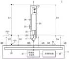
图1是表示本发明的第一实施方式的位置检测系统1的结构的图。如该图所示,位置检测系统1具备触控笔2和电子设备3而构成。其中,电子设备3是例如平板型的计算机,具有构成触摸面3t的传感器30、传感器控制器31、对包含它们的传感器控制器31的各部进行控制的系统控制器32。FIG. 1 is a diagram showing the configuration of a
触控笔2及传感器控制器31分别是与相互具有互换性的方式A(第一方式)及方式B(第二方式)对应的双触控笔及双控制器。方式A、B都对应于触控笔2与传感器控制器31之间的双向通信。方式A、B带有优先顺位,对于方式A设定比方式B高的优先顺位。The stylus 2 and the
图1中的虚线箭头C1~C5表示使用者对触控笔2进行操作的典型的循环。而且,图1所示的传感范围SR表示通过触控笔2接收传感器控制器31发送的上行链路信号US,或者通过传感器控制器31接收触控笔2发送的下行链路信号DS,而触控笔2及传感器控制器31中的任一方能够检测另一方的范围。The dashed arrows C1 to C5 in FIG. 1 represent a typical cycle in which the user operates the stylus 2 . Moreover, the sensing range SR shown in FIG. 1 indicates that the stylus 2 receives the uplink signal US sent by the
使用者使用触控笔2在触摸面3t上描绘线时,反复进行使触控笔2从传感范围SR之外向传感范围SR内移动(下行)(C1、C2),在触摸面3t上以描绘所希望的轨迹的方式移动之后(C3),从传感范围SR内向传感范围SR外移动(上行)(C4、C5)这样的一系列的循环。在本说明书中,将在下行操作中触控笔2进入传感范围SR的情况称为第一下笔PD1,而且将触控笔2与触摸面3t接触的情况称为第二下笔PD2。When the user draws a line on the
如图1所示,触控笔2具有芯体20、电极21、笔压检测部22、开关23、信号处理部24、电源25及指示器26。As shown in FIG. 1 , the stylus 2 includes a core 20 ,
芯体20是以其长度方向与触控笔2的笔轴方向一致的方式配置的棒状的构件,构成触控笔2的笔尖。在芯体20的前端部的表面涂布导电性材料,构成电极21。芯体20的后端部与笔压检测部22抵接。笔压检测部22是检测与将触控笔2的笔尖按压于传感器控制器31的触摸面3t等时向芯体20的前端施加的压力(向芯体20施加的笔压)对应的笔压水平的结构,在具体的例子中,由根据笔压而静电电容变化的可变电容模块构成。The core 20 is a rod-shaped member arranged so that the longitudinal direction thereof coincides with the pen axis direction of the stylus pen 2 , and constitutes the pen tip of the stylus pen 2 . A conductive material is applied to the surface of the front end portion of the core body 20 to constitute the
电极21是设置于芯体20的附近的导电体,通过配线而与信号处理部24电连接。在触控笔2朝向传感器控制器31发送下行链路信号DS时,从信号处理部24对于电极21供给下行链路信号DS,对应于此,在电极21感应出与下行链路信号DS的内容对应的电荷。由此,后述的传感器30内的静电电容产生变化,传感器控制器31通过检测该变化来接收下行链路信号DS。而且,当传感器控制器31发送的上行链路信号US到达电极21时,在电极21感应出与到达的上行链路信号US对应的电荷。信号处理部24通过检测这样在电极21感应出的电荷,来接收上行链路信号US。The
开关23是例如设置于触控笔2的壳体的侧面的侧开关,作为能够受理使用者的操作的输入部发挥功能。具体而言,根据使用者的操作的状态(按下状态),将表示自身的按下状态的开关信息向信号处理部24输出。开关信息是表示例如接通和断开这2个状态的任一方的信息。The
信号处理部24具有:经由电极21来接收传感器控制器31通过方式A或方式B发送的上行链路信号US的功能;通过方式A或方式B而生成下行链路信号DS,经由电极21朝向传感器控制器31发送的功能;基于通过笔压检测部22检测的笔压水平来检测第二下笔PD2(向触摸面3t的接触)的功能。信号处理部24使用方式A、B中的哪个根据触控笔2的动作模式来决定,关于这一点在后文叙述。The
如后所述,上行链路信号US存在包含各种指令的情况,该情况下的信号处理部24通过对接收到的上行链路信号US进行解调及解密而取得指令,按照取得的指令进行下行链路信号DS的生成。具体而言,基于指令的指示,生成包含通过笔压检测部22检测的笔压水平、从开关23输出的开关信息等各种信息的下行链路信号DS。As will be described later, the uplink signal US may include various commands. In this case, the
另外,信号处理部24在未图示的存储器内保持触控笔2的固有ID。固有ID是在触控笔2对应的多个方式(这种情况下为方式A、B)中的任一方式下都能同样使用的信息,包含表示触控笔2对应的多个方式的信息。信号处理部24在通过上行链路信号US内包含的指令而被指示的情况下,或者以与上行链路信号US的接收或包含第二下笔PD2的某些契机对应的定时自发地,向下行链路信号DS内发送包含其固有ID的全部或一部分(至少包含传感器控制器31为了掌握触控笔2对应于方式A的情况而足够的信息)的功能信息。In addition, the
电源25是用于向信号处理部24供给动作电力(直流电压)的结构,由例如圆筒型的AAAA电池构成。The
指示器26是用于将与触控笔2相关的各种信息向使用者通知的显示单元,由例如发光二极管构成。关于该指示器26,通过后述的第三实施方式进行详细说明。The
图2是表示传感器控制器31的结构的图。该图也示出传感器30的结构。如该图所示,传感器30具有多个线状电极30X与多个线状电极30Y配置成矩阵状的结构,通过上述线状电极30X、30Y而与触控笔2进行电容耦合。该传感器30不仅使用于触控笔2而且也使用于手指的检测。而且,传感器控制器31具有发送部60、选择部40、接收部50、逻辑部70及MCU80而构成。FIG. 2 is a diagram showing the configuration of the
发送部60是用于通过方式A或方式B来生成上行链路信号US并发送的电路,例如,包括图案供给部61、开关62、扩散处理部63、代码列保持部64及发送保护部65而构成。需要说明的是,在此说明的发送部60的具体的结构为例示,有时根据方式而不同。而且,在方式A、B需要互不相同的结构的发送部60的情况下,只要将各个结构并设在1个发送部60内,并选择性地使其动作即可。发送部60使用方式A、B中的哪个根据传感器控制器31的动作模式来决定,关于这一点在后文叙述。The
图案供给部61保持检测图案c1,具有按照从逻辑部70供给的控制信号ctrl_t1的指示,在规定的连续发送期间(例如,3msec)之间,连续地反复输出与检测图案c1对应的信号(或位列)的功能。而且,也具有该连续发送期间刚结束之后,或者后述的控制信息c2的发送开始时,将规定的划分图案STP至少连续输出2次的功能。需要说明的是,在图2中,将图案供给部61设置在发送部60内,但也可以设置在MCU80内。The
检测图案c1是触控笔2为了检测传感器控制器31的存在而使用的符号的值的图案,事先(在触控笔2检测传感器控制器31之前)由触控笔2已知。符号是在发送处理中使用于调制的信息的单位(发送信号表现的信息的单位),是在接收处理中对作为接收信号的1符号进行解调而得到的信息的单位。符号的值可以包括被转换成位列的值(以下,称为“位列对应值”)和通过接收到符号的触控笔2未转换成位列的值(以下,称为“位列非对应值”)。如后述的表1所示,前者的符号取得2的幂乘的个数的值,能够与“0001”等位列建立对应。这样通过位列而标记的各符号的位长根据扩散处理部63的规格来决定。另一方面,后者的符号取得1个以上(例如2个)的值,如后述的表1所示,采取与标记为“P”“M”等的位列未建立对应的值。在后述的表1所示的一例中,“P”和“M”分别与规定的扩散代码列和其反转代码列建立对应。The detection pattern c1 is a pattern of values of symbols used by the stylus 2 to detect the presence of the
检测图案c1由位列非对应值的图案表示。具体而言,由“PMPMPM…”那样2个位列非对应值“P”“M”的反复构成。The detection pattern c1 is represented by a pattern of non-corresponding values in the bit sequence. Specifically, it is constituted by the repetition of two non-corresponding values "P" and "M" in two bit sequences such as "PMPMPM...".
划分图案STP是用于将上述连续发送期间的结束向触控笔2通知的符号的图案,由在检测图案c1的反复中未出现的符号的图案构成。列举一例时,如上所述在检测图案c1如“PMPMPM…”那样由2个位列非对应值“P”“M”的反复构成的情况下,划分图案STP可以由使位列非对应值“P”连续2次而成的图案“PP”构成。也可以使划分图案STP与检测图案c1的结构颠倒,通过“PM”构成划分图案而通过“PP”构成检测图案c1。The division pattern STP is a pattern of symbols for notifying the stylus pen 2 of the end of the continuous transmission period, and is composed of a pattern of symbols that do not appear in the repetition of the detection pattern c1. As an example, in the case where the detection pattern c1 is constituted by the repetition of two non-corresponding values "P" and "M" in the bit sequence as described above, such as "PMPMPM...", the division pattern STP can be composed of the non-corresponding value " P" consists of a pattern "PP" formed twice consecutively. The structure of the division pattern STP and the detection pattern c1 may be reversed, and the division pattern may be constituted by "PM" and the detection pattern c1 may be constituted by "PP".
开关62具有基于从逻辑部70供给的控制信号ctrl_t2而旋转图案供给部61及MCU80中的任一方,并将选择的一方的输出向扩散处理部63供给的功能。在开关62选择了图案供给部61的情况下,向扩散处理部63供给检测图案c1或划分图案STP。另一方面,在开关62选择了MCU80的情况下,从MCU80向扩散处理部63供给控制信息c2。The
控制信息c2是包含表示向触控笔2的指示内容的指令的信息,由MCU80生成。控制信息c2包含与可变长的位列建立对应的符号的值(例如0~15),与触控笔2之间事先未共有该值,这一点与检测图案c1不同。而且,控制信息c2由表示上述的规定位长的2的幂乘的个数(8值)的值的值“D”来表示,这一点与包含值“P”“M”的检测图案c1不同。The control information c2 is information including a command indicating the content of the instruction to the stylus pen 2 , and is generated by the
代码列保持部64具有基于从逻辑部70供给的控制信号ctrl_t3来生成并保持具有自相关特性的11片长的扩散代码PN的功能。代码列保持部64保持的扩散代码PN向扩散处理部63供给。The code
扩散处理部63具有基于经由开关62供给的符号的值(通过扩散处理部63的处理而由发送信号表现的信息)对通过代码列保持部64保持的扩散代码PN进行调制,由此得到12片长的发送片列的功能。以下,关于该功能,列举具体例进行说明。The
在以下说明的例子中,将检测图案c1、划分图案STP、控制信息c2分别通过位列对应值0~15(对应位列“0000”~“1111”)及位列非对应值“P”“M”的组合构成。而且,代码列保持部64保持的扩散代码PN为“00010010111”。这种情况下,扩散处理部63按照以下的表1,将各符号的值(0~15以及P及M)转换成发送片列。In the example described below, the detection pattern c1, the division pattern STP, and the control information c2 are respectively associated with the bit string corresponding values 0 to 15 (corresponding to the bit string "0000" to "1111") and the bit string non-corresponding value "P" "" The combination of M". Further, the diffusion code PN held by the code
[表1][Table 1]

如表1所示,在该例中,首先,符号的值“P”转换成在扩散代码PN“00010010111”的开头附加“1”而成的发送片列。而且,符号的值“0”~“7”分别被转换成使扩散代码PN“00010010111”以表1所示的移位量巡回移位而成的代码列的开头附加“1”而成的发送片列。其他的符号的值“M”“8”~“15”分别被转换成使与符号的值“P”“0”~“7”对应的发送片列反转而成的发送片列。As shown in Table 1, in this example, first, the value "P" of the symbol is converted into a transmission chip sequence in which "1" is added to the beginning of the spreading code PN "00010010111". Then, the values of the symbols "0" to "7" are converted into transmissions in which "1" is added to the beginning of the code sequence obtained by round-robin shifting the spread code PN "00010010111" by the shift amount shown in Table 1. slice row. The values "M", "8" to "15" of the other symbols are converted into transmission slice sequences obtained by inverting the transmission slice sequences corresponding to the values "P", "0" to "7" of the symbols, respectively.
扩散处理部63通过以上那样的转换处理而取得发送片列,向发送保护部65供给。The
发送保护部65具有如下的功能:基于从逻辑部70供给的控制信号ctrl_t4,在上行链路信号US的发送期间与接收来自触控笔2的信号的接收期间之间插入为了切换发送动作与接收动作而不进行发送和接收这两方的期间即保护期间。The
选择部40是基于逻辑部70的控制来切换从传感器30发送信号的发送期间与通过传感器30接收信号的接收期间的开关。具体而言,选择部40包含开关44x、44y、导体选择电路41x、41y而构成。开关44x以基于从逻辑部70供给的控制信号sTRx,在发送期间将发送部60的输出端连接于导体选择电路41x的输入端,在接收期间将导体选择电路41x的输出端连接于接收部50的输入端的方式进行动作。开关44y以基于从逻辑部70供给的控制信号sTRy,在发送期间将发送部60的输出端连接于导体选择电路41y的输入端,在接收期间将导体选择电路41y的输出端连接于接收部50的输入端的方式进行动作。导体选择电路41x以基于从逻辑部70供给的控制信号selX,选择多个线状电极30X中的1个或多个,并将选择出的线状电极连接于开关44x的方式进行动作。导体选择电路41y以基于从逻辑部70供给的控制信号selY,选择多个线状电极30Y中的1个或多个,并将选择出的线状电极连接于开关44y的方式进行动作。通过导体选择电路41x、41y选择多个线状电极30X或多个线状电极30Y的是例如从触摸面3t的整面发送上行链路信号US的情况。The
接收部50是用于按照逻辑部70的控制信号ctrl_r,通过方式A或方式B来接收下行链路信号DS的电路,具体而言,包含放大电路51、检波电路52及模拟数字(AD)变换器53而构成。需要说明的是,在此说明的接收部50的具体的结构也是例示,有时根据方式而不同。而且,在方式A、B需要互不相同的结构的接收部50的情况下,只要将各个结构并设在1个接收部50内,并选择性地使其动作即可。接收部50使用方式A、B中的哪个根据传感器控制器31的动作模式来决定,但是关于这一点在后文叙述。The receiving
放大电路51将从选择部40供给的下行链路信号DS放大并输出。检波电路52是生成与放大电路51的输出信号的水平对应的电压的电路。AD变换器53是通过将从检波电路52输出的电压以规定时间间隔进行采样而生成数字信号的电路。AD变换器53输出的数字信号向MCU80供给。The
逻辑部70及MCU80是对发送部60及接收部50等的收发动作进行控制的控制部。具体而言,MCU80是在内部具有ROM及RAM,基于规定的程序进行动作的微处理器。另一方面,逻辑部70构成为,基于MCU80的控制而输出上述的各控制信号。MCU80还构成为,基于从AD变换器53供给的数字信号来导出表示触控笔2的位置的坐标数据x、y等,进行对系统控制器32输出的处理及在从AD变换器53供给的数字信号表示某些数据的情况下取得该数据并对系统控制器32输出的处理。The
图3是本实施方式的触控笔2及传感器控制器31的示意转变图。如该图所示,本实施方式的触控笔2及传感器控制器31构成为,以未确定模式P、进行方式A下的通信的动作模式A(第一动作模式)、进行方式B下的通信的动作模式B(第二动作模式)中的任一模式进行动作。其中,未确定模式P是指还未检测到成为通信对方的装置的状态。在未确定模式P中,未决定应以动作模式A、B中的哪个进行动作,如后所述,使基于方式A、B的信号的收发交替反复。未确定模式P也可以称为以方式A、B等多个动作模式交替地进行动作的双模式,作为检测任1个传感器控制器31或触控笔2的模式也可称为发现模式。需要说明的是,触控笔2可以进行根据这些动作模式的转变来切换指示器26的显示的处理。关于这一点,在后述的第三实施方式中进行说明。FIG. 3 is a schematic transition diagram of the stylus 2 and the
在此,一边参照图4及图5,一边说明在与方式A、B对应的触控笔2及传感器控制器31进行本发明的背景技术的动作时产生的课题。需要说明的是,参照图4及图5说明的触控笔2及传感器控制器31的动作除了在后文特别说明的点之外,也在本实施方式的动作中执行。Here, with reference to FIGS. 4 and 5 , a problem that occurs when the stylus 2 and the
图4是表示在触控笔2及传感器控制器31进行本发明的背景技术的动作时在触控笔2及传感器控制器31之间收发的信号的图。在该图的例子中,在时刻t0产生第一下笔PD1,在时刻t1产生第二下笔PD2。第一下笔PD1产生之前的时点的触控笔2及传感器控制器31各自的动作模式如图4所示在原则上都成为未确定模式P。FIG. 4 is a diagram showing signals transmitted and received between the stylus pen 2 and the
在未确定模式P中,触控笔2交替地反复进行基于方式A的上行链路信号US的接收动作及基于方式B的上行链路信号US的接收动作,传感器控制器31依次反复进行基于方式A的上行链路信号US的发送动作、基于方式A的下行链路信号DS的接收动作、基于方式B的上行链路信号US的发送动作、及基于方式B的下行链路信号DS的接收动作。在此,各信号的接收动作及发送动作持续执行分别预先确定的规定时间。这一点关于后述的各信号的接收动作及发送动作也同样。而且,在各方式,基于传感器控制器31的上行链路信号US的发送动作的周期和基于触控笔2的上行链路信号US的接收动作的周期构成为避免任一方成为另一方的倍数。这是为了避免尽管传感器控制器31发送的上行链路信号US到达触控笔2,但是触控笔2始终无法将其接收这样的事态的发生。而且,基于各方式的接收动作的持续时间(上述规定时间)与在后述的图6中从时刻t1开始触控笔2执行的上行链路信号US的接收动作的持续时间同样,优选至少设为对应的上行链路信号US的发送周期(基于传感器控制器31的发送的周期)以上的时间。而且,触控笔2的接收动作为了电源25(图1)的节约,优选也如图4所示,空出不执行接收动作的休止期间而反复执行。In the undetermined mode P, the stylus pen 2 alternately repeats the operation of receiving the uplink signal US based on the method A and the receiving operation of the uplink signal US based on the method B, and the
作为由第一下笔PD1及第二下笔PD2的产生引起的触控笔2及传感器控制器31的模式转变而最优选的是在时刻t0与时刻t1之间(即,第二下笔PD2产生之前),触控笔2及传感器控制器31都成为动作模式A。这通过如下来实现:触控笔2接收基于方式A的上行链路信号US,由此,传感器控制器31接收由开始了动作模式A下的动作的触控笔2发送的下行链路信号DS,由此传感器控制器31也开始动作模式A下的动作这样的一系列的处理在时刻t0与时刻t1之间进行。As the mode transition of the stylus 2 and the
然而,在使用者快速地操作触控笔2而时刻t0与时刻t1之间缩短了的情况下等,如图4例示那样,即使经过时刻t1在一段时间,也会产生触控笔2无法接收上行链路信号US这样的事态。在图4的例子中,成为时刻t1后的时刻t2好容易触控笔2接收通过方式A发送的上行链路信号US,其结果是触控笔2成为动作模式A,在之后的时刻t3,接收到通过方式A发送的下行链路信号DS的传感器控制器31成为动作模式A,基于方式A的触控笔2与传感器控制器31之间的通信开始。即,从在时刻t1产生第二下笔PD2至在时刻t3开始基于方式A的触控笔2与传感器控制器31之间的通信开始为止,产生时间t3-t1量的延迟。该延迟的产生是本实施方式的背景技术中的课题之一。However, when the user operates the stylus 2 quickly and the time between the time t0 and the time t1 is shortened, as illustrated in FIG. 4 , the stylus 2 may not be able to receive the reception even if the time t1 elapses for a certain period of time. Uplink signal US such a situation. In the example of FIG. 4 , at time t2 after time t1, the stylus pen 2 can easily receive the uplink signal US sent by the mode A, and as a result, the stylus pen 2 enters the operation mode A, and at the subsequent time t3, The
图5也是表示在触控笔2及传感器控制器31进行本发明的背景技术的动作时在触控笔2及传感器控制器31之间收发的信号的图。该图的例子在触控笔2的接收动作的定时(相对于传感器控制器31的发送动作的相对的定时)的点上与图4所示的例子不同。FIG. 5 is also a diagram showing signals transmitted and received between the stylus pen 2 and the
作为上述差异的结果,在图5的例子中,在时刻t2,触控笔2接收通过方式B发送的上行链路信号US,成为动作模式B。接收到该情况,在时刻t3传感器控制器31也成为动作模式B,通过方式B而开始触控笔2与传感器控制器31之间的通信。方式B比方式A的优先顺位低,因此在与方式A、B这两方对应的触控笔2及传感器控制器31之间这样开始基于方式B的通信的情况不优选,希望提前切换为基于方式A的通信。这是本实施方式的背景技术的课题的另一个。As a result of the above difference, in the example of FIG. 5 , at time t2 , the stylus pen 2 receives the uplink signal US transmitted by the method B, and the operation mode B is set. Upon receiving this, the
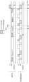
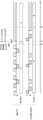
图6是表示在触控笔2及传感器控制器31进行本实施方式的动作时在触控笔2及传感器控制器31之间收发的信号的图。该图特别示出用于避免上述的延迟的触控笔2的动作。FIG. 6 is a diagram showing signals transmitted and received between the stylus pen 2 and the
如图6所示,触控笔2在时刻t1检测到第二下笔PD2之后,如果自身的动作模式还是未确定模式P,则立即开始基于方式A的上行链路信号US的接收动作。该接收动作在接收到基于方式A的上行链路信号US之前,至少持续传感器控制器31的发送周期(图示的周期SP1)以上的时间。由此,如果传感器控制器31发送基于方式A的上行链路信号US,则触控笔2只要不脱离传感范围SR(图1),就能够可靠地接收基于方式A的上行链路信号US。而且,由于在第二下笔PD2的产生后立即开始基于方式A的上行链路信号US的接收动作,因此从第二下笔PD2至基于方式A的通信开始为止的延迟也止于最小限度。As shown in FIG. 6 , after the stylus pen 2 detects the second pen-down PD2 at time t1, if its own operation mode is still the undetermined mode P, it immediately starts receiving the uplink signal US based on the mode A. This reception operation is continued for at least a time equal to or longer than the transmission period (period SP1 shown in the figure) of the
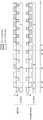
图7也是表示本实施方式的在触控笔2及传感器控制器31之间收发的信号的图。该图特别示出在基于优先顺位低的方式B的通信开始之后,向基于优先顺位高的方式A的通信的切换用的触控笔2及传感器控制器31的动作。这样的事态即使在触控笔2及传感器控制器31进行本实施方式的动作时,例如,在时刻t0与时刻t1之间触控笔2接收到基于方式B的上行链路信号US时等也会发生。FIG. 7 is also a diagram showing signals transmitted and received between the stylus pen 2 and the
如图7所示,开始了动作模式B下的动作的触控笔2在任意的时刻t4发送包含固有ID的下行链路信号DS(D1。第一信号)。该任意的时刻t4可以设为与来自传感器控制器31的上行链路信号US或其中包含的指令对应的时刻,也可以设为与触控笔2开始了动作模式B下的动作的时刻t2对应的时刻。传感器控制器31当接收到该下行链路信号DS(D1)时,通过解调及解密来取得其中含有的固有ID。并且,基于取得的固有ID来判定触控笔2是否也与方式A对应,在判定为对应的情况下,在时刻t5,发送包含表示向动作模式A切换的切换指示的指令的上行链路信号US(D2。第二信号)。触控笔2在时刻t6接收到该上行链路信号US(D2)时,通过解调及解密来取得其中包含的上述切换指示。并且,按照取得的切换指示,在时刻t7将自身的动作模式切换为动作模式A。As shown in FIG. 7, the stylus pen 2 which started the operation|movement in operation mode B transmits the downlink signal DS (D1. 1st signal) containing a unique ID at arbitrary time t4. The arbitrary time t4 may be set to correspond to the uplink signal US from the
从传感器控制器31发送上行链路信号US(D2)至触控笔2转变为动作模式A为止的所需时间可以预先决定作为触控笔2的规格的一部分。因此,传感器控制器31能够预先已知接受到切换指示的触控笔2向动作模式A转变的时刻t7,因此对应于时刻t7进行将自身的动作模式切换为动作模式A的处理。由此,在触控笔2与传感器控制器31之间开始基于优先顺位高的方式A的通信。The time required from when the
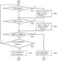
图8~图10是表示本实施方式的触控笔2的动作的处理流程图。以下,一边参照这些图,一边更详细地说明本实施方式的触控笔2的动作。8 to 10 are processing flowcharts showing operations of the stylus pen 2 according to the present embodiment. Hereinafter, the operation of the touch pen 2 of the present embodiment will be described in more detail with reference to these figures.
如图8所示,触控笔2首先将自身的动作模式设为未确定模式P(步骤S11)。然后,分别检测方式A下的接收开始定时的到来、方式B下的接收开始定时的到来、第二下笔的产生(步骤S12、S14)。在方式A下的接收开始定时到来的情况下及第二下笔产生的情况下,触控笔2使基于方式A的上行链路信号US的接收动作起动(步骤S13)。第二下笔产生时的该接收动作如上所述在接收到基于方式A的上行链路信号US之前,至少持续传感器控制器31的发送周期(图6所示的周期SP1)以上的时间。而且,在方式B下的接收开始定时到来的情况下,触控笔2使基于方式B的上行链路信号US的接收动作起动(步骤S15)。As shown in FIG. 8 , the stylus pen 2 first sets its own operation mode to the undetermined mode P (step S11 ). Then, the arrival of the reception start timing in the mode A, the arrival of the reception start timing in the mode B, and the generation of the second pen stroke are detected respectively (steps S12 and S14). When the reception start timing in the method A arrives and when the second pen-down occurs, the stylus pen 2 starts the reception operation of the uplink signal US by the method A (step S13 ). The reception operation at the time of the second stroke generation is continued for at least the transmission period (period SP1 shown in FIG. 6 ) of the
触控笔2还通过在步骤S13或步骤S15中开始的接收动作来判定是否接收到上行链路信号US(步骤S16),在通过在步骤S13中开始的接收动作而判定为接收到上行链路信号US的情况下(即,接收到基于方式A的上行链路信号US的情况下)将自身的动作模式向动作模式A(步骤S17),在通过在步骤S15中开始的接收动作而判定为接收到上行链路信号US的情况下(即,接收到基于方式B的上行链路信号US的情况下)将自身的动作模式切换为动作模式B(步骤S18)。The stylus pen 2 also determines whether or not the uplink signal US has been received by the reception operation started in step S13 or step S15 (step S16 ), and determines that the uplink signal US has been received by the reception operation started in step S13 In the case of the signal US (that is, when the uplink signal US based on the scheme A is received), the operation mode is changed to the operation mode A (step S17), and it is determined by the reception operation started in step S15 as When the uplink signal US is received (that is, when the uplink signal US based on the scheme B is received), the operation mode of itself is switched to the operation mode B (step S18).
图9示出开始了动作模式A下的动作之后的触控笔2的动作。如该图所示,触控笔2分别检测发送开始定时的到来、接收开始定时的到来(步骤S21、S23)。并且,在发送开始定时到来的情况下,使基于方式A的下行链路信号DS的发送动作起动(步骤S22),在接收开始定时到来的情况下,使基于方式A的上行链路信号US的接收动作起动(步骤S24)。FIG. 9 shows the operation of the stylus pen 2 after the operation in the operation mode A is started. As shown in the figure, the touch pen 2 detects the arrival of the transmission start timing and the arrival of the reception start timing, respectively (steps S21 and S23 ). Then, when the transmission start timing comes, the transmission operation of the downlink signal DS based on the scheme A is started (step S22), and when the reception start timing comes, the uplink signal US based on the scheme A is activated. The reception operation is started (step S24).
触控笔2还通过在步骤S24中开始的接收动作来判定是否接收到上行链路信号US(步骤S25),在判定为接收到的情况下,返回步骤S21而重复进行处理。另一方面,在判定为未接收到的情况下,使自身的动作模式返回未确定模式P(步骤S26),并使处理返回图8的步骤S12。该处理是在触控笔2从触摸面3t离开的情况下为了使触控笔2返回未确定模式P而执行的处理。The stylus pen 2 also determines whether or not the uplink signal US has been received by the reception operation started in step S24 (step S25 ). On the other hand, when it is determined that the reception is not received, the operation mode of the self is returned to the undetermined mode P (step S26 ), and the process is returned to step S12 of FIG. 8 . This processing is executed to return the stylus pen 2 to the undetermined mode P when the stylus pen 2 is separated from the
图10示出开始了动作模式B下的动作之后的触控笔2的动作。如该图所示,触控笔2分别检测发送开始定时的到来、接收开始定时的到来(步骤S31、S33)。并且,在发送开始定时到来的情况下,使基于方式B的下行链路信号DS的发送动作起动(步骤S32),在接收开始定时到来的情况下,使基于方式B的上行链路信号US的接收动作起动(步骤S34)。FIG. 10 shows the operation of the stylus pen 2 after the operation in the operation mode B is started. As shown in the figure, the touch pen 2 detects the arrival of the transmission start timing and the arrival of the reception start timing, respectively (steps S31 and S33 ). Then, when the transmission start timing arrives, the transmission operation of the downlink signal DS based on the scheme B is started (step S32), and when the reception start timing arrives, the transmission operation of the uplink signal US based on the scheme B is started. The reception operation is started (step S34).
触控笔2还通过在步骤S34中开始的接收动作来判定是否接收到上行链路信号US(步骤S35),在判定为接收到的情况下,判定其中是否含有向动作模式A的切换指示(步骤S36)。其结果是,在判定为含有的情况下,将自身的动作模式切换为动作模式A(步骤S37),使处理向图9的步骤S21转移。另一方面,在判定为不含有的情况下,返回步骤S31而重复进行处理。The stylus pen 2 also determines whether or not the uplink signal US has been received by the reception operation started in step S34 (step S35 ), and when it is determined that it has been received, determines whether or not a switching instruction to the operation mode A is included ( step S36). As a result, when it is determined that it is included, the operation mode of the self is switched to the operation mode A (step S37 ), and the process is shifted to step S21 in FIG. 9 . On the other hand, when it is determined that it is not included, the process returns to step S31 and the processing is repeated.
在判定为在步骤S35中未接收到的情况下,触控笔2使自身的动作模式返回未确定模式P(步骤S38),并使处理返回图8的步骤S12。该处理与图9的步骤S26同样是在触控笔2从触摸面3t分离的情况下为了使触控笔2返回未确定模式P而执行的处理。When it is determined that it has not been received in step S35, the stylus pen 2 returns its own operation mode to the undetermined mode P (step S38), and returns the process to step S12 in FIG. 8 . This processing is performed to return the stylus pen 2 to the undetermined mode P when the stylus pen 2 is separated from the
图11~图13是表示本实施方式的传感器控制器31进行的处理的处理流程图。以下,参照这些图,更详细地说明本实施方式的传感器控制器31的动作。11 to 13 are processing flowcharts showing processing performed by the
如图11所示,传感器控制器31首先将自身的动作模式设为未确定模式P(步骤S41)。然后,分别检测方式A下的接收开始定时的到来、方式A下的发送开始定时的到来、方式B下的接收开始定时的到来、方式B下的发送开始定时的到来(步骤S42、S44、S46、S48)。在方式A下的接收开始定时到来的情况下,传感器控制器31使基于方式A的下行链路信号DS的接收动作起动(步骤S43)。同样,传感器控制器31在方式A下的发送开始定时到来的情况下,使基于方式A的上行链路信号US的发送动作起动(步骤S45),在方式B下的接收开始定时到来的情况下,使基于方式B的下行链路信号DS的接收动作起动(步骤S47),在方式B下的发送开始定时到来的情况下,使基于方式B的上行链路信号US的发送动作起动(步骤S49)。As shown in FIG. 11 , the
传感器控制器31还通过在步骤S43或步骤S47中开始的接收动作来判定是否接收到下行链路信号DS(步骤S50)。并且,在通过在步骤S43中开始的接收动作而判定为接收到下行链路信号DS的情况下(即,接收到基于方式A的下行链路信号DS的情况下)将自身的动作模式切换为动作模式A(步骤S51),在通过在步骤S47中开始的接收动作而判定为接收到下行链路信号DS的情况下(即,接收到基于方式B的下行链路信号DS的情况下)将自身的动作模式切换为动作模式B(步骤S52)。The
图12示出开始了动作模式A下的动作之后的传感器控制器31的动作。如该图所示,传感器控制器31分别检测发送开始定时的到来、接收开始定时的到来(步骤S61、S63)。并且,在发送开始定时到来的情况下,使基于方式A的上行链路信号US的发送动作起动(步骤S62),在接收开始定时到来的情况下,使基于方式A的下行链路信号DS的接收动作起动(步骤S64)。FIG. 12 shows the operation of the
传感器控制器31还通过在步骤S64中开始的接收动作来判定是否接收到下行链路信号DS(步骤S65),在判定为接收到的情况下,返回步骤S61而重复进行处理。另一方面,在判定为未接收到的情况下,使自身的动作模式返回未确定模式P(步骤S66),并使处理返回图11的步骤S42。该处理是在触控笔2从触摸面3t分离的情况下为了使传感器控制器31返回未确定模式P而执行的处理。The
图13示出动作模式B下的动作开始之后的传感器控制器31的动作。如该图所示,传感器控制器31分别检测发送开始定时的到来、接收开始定时的到来(步骤S71、S73)。并且,在发送开始定时到来的情况下。使基于方式B的上行链路信号US的发送动作起动(步骤S72),在接收开始定时到来的情况下,使基于方式B的下行链路信号DS的接收动作起动(步骤S74)。FIG. 13 shows the operation of the
传感器控制器31还判定是否将向动作模式A切换的切换指示包含于上行链路信号US进行了发送(步骤S75),在判定为进行了发送的情况下,触控笔2对应于向动作模式A转变的定时,将自身的动作模式切换为动作模式A(步骤S76)。然后,向图12的步骤S61转移而继续处理。The
在步骤S75中判定为未发送的情况下,接下来,传感器控制器31通过在步骤S74中开始的接收动作来判定是否接收到下行链路信号DS(步骤S77)。在此判定为未接收到的情况下,传感器控制器31使自身的动作模式返回未确定模式P(步骤S78),并使处理返回图11的步骤S42。该处理与图12的步骤S66同样是在触控笔2从触摸面3t分离的情况下为了使传感器控制器31返回未确定模式P而执行的处理。When it is determined in step S75 that the transmission is not performed, the
在步骤S77中判定为接收到的情况下,传感器控制器31判定接收到的下行链路信号DS是否含有表示触控笔2对应于方式A的功能信息(步骤S79)。具体而言,功能信息如上所述是表示触控笔2的固有ID的全部或一部分的信息。在判定为下行链路信号DS含有表示触控笔2对应于方式A的功能信息的情况下,传感器控制器31设定包含向动作模式A的切换指示的指令作为通过上行链路信号US发送的信息之一(步骤S80)。这样设定的指令在接下来执行步骤S72时被发送。并且,在之后的步骤S75中,判定为将向动作模式A切换的切换指示包含于上行链路信号US进行了发送。作为上述的处理的结果,触控笔2及传感器控制器31这双方转变为动作模式A。When it is determined in step S77 that it has been received, the
如以上说明所述,根据本实施方式的由触控笔2执行的方法,触控笔2在向触摸面3t的接触后能够立即使基于方式A的信号的接收动作起动。因此,能够缩短从与触摸面3t接触至触控笔2设定为动作模式A为止的时间。As described above, according to the method executed by the stylus pen 2 of the present embodiment, the stylus pen 2 can start the reception operation of the signal by the method A immediately after the touch of the stylus pen 2 on the
另外,根据本实施方式的由触控笔2和传感器控制器31执行的方法,即使触控笔2的动作模式是进行基于方式B的信号的收发的动作模式B,按照掌握了触控笔2对应于方式A的传感器控制器31的指示,也能够将触控笔2的动作模式切换为动作模式A。因此,在触控笔2与传感器控制器31之间,能够开始基于方式A的通信。In addition, according to the method executed by the stylus pen 2 and the
接下来,说明本发明的第二实施方式。本实施方式的触控笔2及传感器控制器31取代方式B而对应于从触控笔2向传感器控制器31的单向通信的方式C,这一点与第一实施方式的触控笔2及传感器控制器31不同,在其他的点上同样,因此以下着眼于不同点进行说明。需要说明的是,对方式A设定比方式C高的优先顺位。Next, a second embodiment of the present invention will be described. The stylus 2 and the
图14是本实施方式的触控笔2及传感器控制器31的示意转变图。如该图所示,本实施方式的触控笔2及传感器控制器31构成为,以未确定模式P、进行方式A下的通信的动作模式A(第一动作模式)、进行方式C下的通信的动作模式C(第二动作模式)中的任一模式进行动作。FIG. 14 is a schematic transition diagram of the stylus pen 2 and the
在此,一边参照图15,一边说明在对应于方式A、C的触控笔2及传感器控制器31进行本发明的背景技术的动作时产生的课题。需要说明的是,参照图15说明的触控笔2及传感器控制器31的动作除了后文特别说明的点之外,在本实施方式的动作中也被执行。Here, with reference to FIG. 15 , a problem that occurs when the stylus 2 and the
图15是表示在触控笔2及传感器控制器31进行本发明的背景技术的动作的情况下,在触控笔2及传感器控制器31之间收发的信号的图。在该图的例子中,也与图4等的例子同样,在时刻t0产生第一下笔PD1,在时刻t1产生第二下笔PD2。第一下笔PD1产生之前的时点下的触控笔2及传感器控制器31各自的动作模式如图15所示在原则上都成为未确定模式P。FIG. 15 is a diagram showing signals transmitted and received between the stylus pen 2 and the
在未确定模式P中,触控笔2构成为,交替地反复进行基于方式C的下行链路信号DS的发送动作、基于方式A的上行链路信号US的接收动作。但是,在图15的例子中,为了降低消耗电力,而在2次中以1次的比例,省略基于方式A的上行链路信号US的接收动作。在本发明中,这样的动作也包含于“交替地反复进行基于方式C的下行链路信号DS的发送动作和基于方式A的上行链路信号US的接收动作”动作。而且,传感器控制器31构成为,依次反复进行基于方式A的上行链路信号US的发送动作、基于方式A的下行链路信号DS的接收动作、基于方式C的下行链路信号DS的接收动作。在此,触控笔2发送基于方式C的下行链路信号DS的周期和传感器控制器31接收基于方式C的下行链路信号DS的周期构成为避免任一方成为另一方的倍数。关于触控笔2接收基于方式A的上行链路信号US的周期和传感器控制器31发送基于方式A的上行链路信号US的周期也同样。这是为了避免尽管一方的装置发送的信号到达另一方的装置,但是另一方的装置始终无法对其接收这样的事态的发生。In the undetermined mode P, the stylus pen 2 is configured to alternately repeat the transmission operation of the downlink signal DS by the method C and the reception operation of the uplink signal US by the method A. However, in the example of FIG. 15 , in order to reduce power consumption, the reception operation of the uplink signal US based on the scheme A is omitted in the ratio of one time out of two times. In the present invention, such an operation is also included in the operation of "repetitively repeating the transmission operation of the downlink signal DS according to the scheme C and the reception operation of the uplink signal US according to the scheme A". Then, the
在图15的例子中,也是作为由第一下笔PD1及第二下笔PD2的产生引起的触控笔2及传感器控制器31的模式转变而最优选的是在时刻t0与时刻t1之间(即,第二下笔PD2产生之前),触控笔2及传感器控制器31都成为动作模式A。这与图4的情况同样通过如下来实现:触控笔2接收基于方式A的上行链路信号US,由此,传感器控制器31接收通过开始了动作模式A下的动作的触控笔2发送的下行链路信号DS,由此传感器控制器31也开始动作模式A下的动作这样的一系列的处理在时刻t0与时刻t1之间进行。In the example of FIG. 15 as well, it is most preferable that between time t0 and time t1 ( That is, before the second pen-down PD2 is generated), both the stylus 2 and the
然而,在使用者快速地操作触控笔2,时刻t0与时刻t1之间缩短了的情况下、触控笔2无法检测到上行链路信号US的情况下等,如图15例示那样,会产生即使到达时刻t1而触控笔2也仍无法接收上行链路信号US这样的事态。因此,根据背景技术的动作,触控笔2在保持不转变为动作模式A的状态下经过了时刻t1时,立即将自身的动作模式切换为动作模式C。由此,触控笔2专门进行基于方式C的下行链路信号DS的发送动作,因此传感器控制器31也转变为任一动作模式C,开始基于方式C的触控笔2与传感器控制器31之间的通信(时刻t2)。在对应于方式A、C这两方的触控笔2及传感器控制器31之间这样开始基于方式C的通信的情况不优选,因此说起来希望避免基于方式C的通信的开始,或者即使基于方式C的通信开始也希望提前切换为基于方式A的通信。这些是本实施方式的背景技术的课题。However, when the user quickly operates the stylus 2 and the time between time t0 and time t1 is shortened, when the stylus 2 cannot detect the uplink signal US, etc., as illustrated in FIG. 15 , the A situation occurs in which the stylus pen 2 cannot receive the uplink signal US even when the time t1 is reached. Therefore, according to the operation of the background art, the stylus pen 2 immediately switches its own operation mode to the operation mode C when the time t1 has elapsed without changing to the operation mode A. As a result, the stylus pen 2 exclusively performs the transmission operation of the downlink signal DS based on the method C, so the
图16是表示在触控笔2及传感器控制器31进行本实施方式的动作的情况下在触控笔2及传感器控制器31之间收发的信号的图。该图特别示出在未转变为动作模式A的状态下即使经过时刻t1,也不开始基于方式C的通信用的触控笔2的动作。FIG. 16 is a diagram showing signals transmitted and received between the stylus pen 2 and the
如图16所示,触控笔2在时刻t1检测到第二下笔PD2之后,即使自身的动作模式仍为未确定模式P,也不向动作模式C转变,而立即使基于方式A的上行链路信号US的接收动作起动。该接收动作在接收到基于方式A的上行链路信号US之前,至少持续传感器控制器31的发送周期(图示的周期SP2)以上的时间。由此,如果传感器控制器31发送基于方式A的上行链路信号US,则触控笔2只要不脱离传感范围SR(图1),就能够可靠地接收基于方式A的上行链路信号US。因此,不用开始基于方式C的通信而能够使基于方式A的通信开始。As shown in FIG. 16 , after the stylus pen 2 detects the second stroke PD2 at time t1, even if its own operation mode is still in the undetermined mode P, it does not transition to the operation mode C, and immediately starts the uplink based on the mode A. The reception operation of the signal US is started. This reception operation is continued for at least a time equal to or longer than the transmission period (period SP2 shown in the figure) of the
图17也是表示本实施方式的在触控笔2及传感器控制器31之间收发的信号的图。该图特别示出在基于优先顺位低的方式C的通信开始之后,用于切换为基于优先顺位高的方式A的通信的触控笔2及传感器控制器31的动作。如果使用本实施方式的触控笔2及传感器控制器31,则如参照图16说明那样基于方式C的通信未开始,因此基本上应该不需要在此说明的动作,但是由于某些理由而触控笔2对于上行链路信号US的接收失败,其结果是基于方式C的通信也会开始(例如,在后述的图18中,尽管传感器控制器31发送了基于方式A的上行链路信号US,但是触控笔2在步骤S108中对于其接收失败,在步骤S111中将自身的动作模式决定为动作模式C时等),因此需要在此说明的动作。需要说明的是,在此触控笔2以动作模式C进行动作的情况为前提,但是以下说明的动作在触控笔2以未确定模式P进行动作的情况下也同样。FIG. 17 is also a diagram showing signals transmitted and received between the stylus pen 2 and the
如图17所示,以动作模式C进行动作的触控笔2继续发送包含表示自身对应于方式A、C的功能信息(具体而言,固有ID的全部或一部分)的下行链路信号DS(D3。第一信号)。As shown in FIG. 17 , the stylus 2 operating in the operation mode C continues to transmit the downlink signal DS ( D3. First signal).
在第一下笔PD1产生的时刻t0之后的时刻t1当传感器控制器31接收到下行链路信号DS(D3)时,传感器控制器31的动作模式变化为动作模式C。此时,传感器控制器31基于下行链路信号DS(D3)内含有的固有ID,判定触控笔2对应的方式。并且,在判定为触控笔2对应于方式A的情况下,传感器控制器31在这以后每当下行链路信号DS的发送中断时,暂时将自身的动作模式切换为动作模式A,执行基于方式A的上行链路信号US(第二信号)的发送。这样发送的上行链路信号US具有作为向动作模式A的切换指示的作用。When the
触控笔2在如果传感器控制器31进行上述动作则可能发送上行链路信号US的定时,尝试基于方式A的上行链路信号US的接收。具体而言,只要以下行链路信号DS的发送间隔进行基于方式A的上行链路信号US的接收动作即可。但是,必然以发送间隔进行接收动作时,电源25(图1)的消耗增大,因此如图17所示,优选以例如刚检测到第二下笔PD2(时刻t2)之后的下行链路信号DS的发送间隔(时刻t3与时刻t4之间)进行基于方式A的上行链路信号US的接收动作。当然,也可以在检测第二下笔PD2之前的阶段(包括第一下笔PD1与第二下笔PD2之间)进行基于方式A的上行链路信号US的接收动作,由此,触控笔2在时刻t2的到来前能够检测基于方式A的上行链路信号US(在图17中,位于比时刻t1靠后的方式A的上行链路信号US)。The stylus pen 2 attempts to receive the uplink signal US based on the method A at the timing when the
触控笔2在时刻t4接收到基于方式A的上行链路信号US时,将自身的动作模式切换为动作模式A。另一方面,传感器控制器31在将基于方式A的上行链路信号US发送了几次之后,尝试基于方式A的下行链路信号DS的接收。在图17的例子中,在第二次的发送之后实施该尝试,但也可以在第一次的发送之后执行,还可以在第三次以后的发送之后执行。而且,可以遍及多次地尝试基于方式A的下行链路信号DS的接收。这样尝试了基于方式A的下行链路信号DS的接收的结果是,在时刻t5实际接收到基于方式A的下行链路信号DS的传感器控制器31对应于此将自身的动作模式切换为动作模式A,这以后,以动作模式A进行动作。由此,在触控笔2与传感器控制器31之间开始基于方式A的通信。When the stylus pen 2 receives the uplink signal US based on the method A at time t4, it switches its own operation mode to the operation mode A. On the other hand, the
图18~图20是表示本实施方式的触控笔2的动作的处理流程图。以下,一边参照这些图,一边更详细地说明本实施方式的触控笔2的动作。18 to 20 are process flowcharts showing operations of the stylus pen 2 according to the present embodiment. Hereinafter, the operation of the touch pen 2 of the present embodiment will be described in more detail with reference to these figures.
如图18所示,触控笔2首先将自身的动作模式决定为未确定模式P(步骤S101)。然后,分别检测方式A下的接收开始定时的到来、方式C下的发送开始定时的到来(步骤S102、S104)。在方式A下的接收开始定时到来的情况下,触控笔2使基于方式A的上行链路信号US的接收动作起动(步骤S103)。而且,在方式C下的发送开始定时到来的情况下,触控笔2使基于方式C的下行链路信号DS的发送动作起动(步骤S105)。As shown in FIG. 18 , the stylus pen 2 first determines its own operation mode as the undetermined mode P (step S101 ). Then, the arrival of the reception start timing in the method A and the arrival of the transmission start timing in the method C are detected respectively (steps S102 and S104 ). When the reception start timing in the method A comes, the stylus pen 2 starts the reception operation of the uplink signal US by the method A (step S103 ). Then, when the transmission start timing in the method C arrives, the stylus pen 2 starts the transmission operation of the downlink signal DS by the method C (step S105 ).
触控笔2还通过在步骤S103中开始的接收动作来判定是否接收到上行链路信号US(步骤S106),在判定为接收到的情况下(即,接收到基于方式A的上行链路信号US的情况下)将自身的动作模式切换为动作模式A(步骤S110)。The stylus pen 2 also determines whether or not the uplink signal US has been received by the reception operation started in step S103 (step S106 ). In the case of US), it switches its own operation mode to operation mode A (step S110).
触控笔2与基于步骤S106的判定并行地也判定第二下笔PD2是否产生(步骤S107),在判定为产生的情况下,与步骤S103的定期的接收动作另行地使基于方式A的上行链路信号US的接收动作起动(步骤S108)。如上所述,该接收动作在接收到基于方式A的上行链路信号US之前,至少持续传感器控制器31的发送周期(图16所示的周期SP2)以上的时间。然后,通过该接收动作来判定是否接收到上行链路信号US(步骤S109),在判定为接收到的情况下,将自身的动作模式切换为动作模式A(步骤S110),而在判定为未接收到的情况下,将自身的动作模式切换为动作模式C(步骤S111)。在步骤S107中判定为第二下笔PD2未产生时,返回步骤S102而继续处理。The stylus 2 also determines whether or not the second pen-down PD2 has occurred (step S107 ) in parallel with the determination in step S106 . The reception operation of the channel signal US is started (step S108). As described above, this reception operation continues for at least the transmission period (period SP2 shown in FIG. 16 ) of the
图19示出动作模式A下的动作开始之后的触控笔2的动作。如该图所示,触控笔2分别检测发送开始定时的到来、接收开始定时的到来(步骤S121、S123)。然后,在发送开始定时到来的情况下,使基于方式A的下行链路信号DS的发送动作起动(步骤S122),在接收开始定时到来的情况下,使基于方式A的上行链路信号US的接收动作起动(步骤S124)。FIG. 19 shows the operation of the stylus pen 2 after the operation in the operation mode A is started. As shown in the figure, the touch pen 2 detects the arrival of the transmission start timing and the arrival of the reception start timing, respectively (steps S121 and S123 ). Then, when the transmission start timing comes, the transmission operation of the downlink signal DS based on the scheme A is started (step S122), and when the reception start timing comes, the uplink signal US based on the scheme A is activated. The reception operation is started (step S124).
触控笔2还通过在步骤S124中开始的接收动作来判定是否接收到上行链路信号US(步骤S125),在判定为接收到的情况下,返回步骤S121而重复进行处理。另一方面,在判定为未接收到的情况下,使自身的动作模式返回未确定模式P(步骤S126),并使处理返回图18的步骤S102。该处理是在触控笔2从触摸面3t分离的情况下为了使控笔2返回未确定模式P而执行的处理。The stylus pen 2 also determines whether or not the uplink signal US has been received by the reception operation started in step S124 (step S125 ). On the other hand, when it is determined that the reception is not received, the operation mode of the self is returned to the undetermined mode P (step S126 ), and the process is returned to step S102 of FIG. 18 . This processing is executed to return the stylus 2 to the undetermined mode P when the stylus 2 is separated from the
图20示出动作模式C下的动作开始之后的触控笔2的动作。如该图所示,触控笔2进行发送开始定时的到来的检测(步骤S131),在发送开始定时到来的情况下,使基于方式C的下行链路信号DS的发送动作起动(步骤S132)。FIG. 20 shows the operation of the stylus pen 2 after the operation in the operation mode C is started. As shown in the figure, the stylus pen 2 detects the arrival of the transmission start timing (step S131 ), and when the transmission start timing arrives, starts the transmission operation of the downlink signal DS based on the scheme C (step S132 ). .
触控笔2还与基于步骤S131的检测并行地也进行第二下笔PD2是否产生的判定(步骤S133),在判定为产生的情况下,在期待基于传感器控制器31的上行链路信号US的发送的定时,使基于方式A的上行链路信号US的接收动作起动(步骤S134)。该期待的定时是例如基于方式C的下行链路信号DS的发送间隔。并且,在接收到基于方式A的上行链路信号US的情况下,将自身的动作模式切换为动作模式A(步骤S136),使处理向图19的步骤S121转移。在未接收到基于方式A的上行链路信号US的情况下,返回步骤S131而继续动作模式C下的处理。在步骤S133中判定为第二下笔PD2未产生的情况下,返回步骤S131而继续处理。The stylus 2 also performs a determination as to whether or not the second pen-down PD2 has occurred (step S133 ) in parallel with the detection by step S131 . At the timing of transmission, the reception operation of the uplink signal US based on the scheme A is started (step S134). The expected timing is, for example, the transmission interval of the downlink signal DS based on the scheme C. FIG. Then, when the uplink signal US based on the scheme A is received, the operation mode is switched to the operation mode A (step S136 ), and the process is shifted to step S121 in FIG. 19 . When the uplink signal US based on the scheme A has not been received, the process returns to step S131 and the processing in the operation mode C is continued. When it is determined in step S133 that the second pen-down PD2 has not occurred, the process returns to step S131 to continue the process.
图21~图24是表示本实施方式的传感器控制器31进行的处理的处理流程图。以下,参照这些图,更详细地说明本实施方式的传感器控制器31的动作。21 to 24 are processing flowcharts showing processing performed by the
如图21所示,传感器控制器31首先将自身的动作模式决定为未确定模式P(步骤S141)。然后,分别检测方式A下的接收开始定时的到来、方式A下的发送开始定时的到来、方式C下的接收开始定时的到来(步骤S142、S144、S146)。在方式A下的接收开始定时到来的情况下,传感器控制器31使基于方式A的下行链路信号DS的接收动作起动(步骤S143)。同样,传感器控制器31在方式A下的发送开始定时到来的情况下,使基于方式A的上行链路信号US的发送动作起动(步骤S145),在方式C下的接收开始定时到来的情况下,使基于方式C的下行链路信号DS的接收动作起动(步骤S147)。As shown in FIG. 21 , the
传感器控制器31还通过在步骤S143或步骤S147中开始的接收动作来判定是否接收到下行链路信号DS(步骤S148),在通过在步骤S143中开始的接收动作而判定为接收到下行链路信号DS的情况下(即,接收到基于方式A的下行链路信号DS的情况下),将自身的动作模式切换为动作模式A(步骤S149)。另一方面,在通过在步骤S147中开始的接收动作而判定为接收到下行链路信号DS的情况下(即,接收到基于方式C的下行链路信号DS的情况下),将自身的动作模式切换为动作模式C(步骤S150)的基础上,判定该下行链路信号DS是否含有表示触控笔2对应于方式A的功能信息(具体而言,固有ID的全部或一部分)(步骤S151)。在判定为下行链路信号DS不含有表示触控笔2对应于方式A的功能信息的情况下,传感器控制器31使处理向图23的步骤S171转移,开始基于方式C的通常动作。另一方面,在判定为含有的情况下,使处理向图24的步骤S181转移,执行用于使触控笔2转变为动作模式A的处理。The
图22示出开始了动作模式A下的动作之后的传感器控制器31的动作。如该图所示,传感器控制器31分别检测发送开始定时的到来、接收开始定时的到来(步骤S161、S163)。然后,在发送开始定时到来的情况下,使基于方式A的上行链路信号US的发送动作起动(步骤S162),在接收开始定时到来的情况下,使基于方式A的下行链路信号DS的接收动作起动(步骤S164)。FIG. 22 shows the operation of the
传感器控制器31还通过在步骤S164中开始的接收动作来判定是否接收到下行链路信号DS(步骤S165),在判定为接收到的情况下,返回步骤S161而重复进行处理。另一方面,在判定为未接收到的情况下,使自身的动作模式返回未确定模式P(步骤S166),并使处理返回图21的步骤S142。该处理是在触控笔2从触摸面3t分离的情况下为了使传感器控制器31返回未确定模式P而执行的处理。The
图23示出动作模式C下的动作开始之后的传感器控制器31的动作。如该图所示,传感器控制器31检测接收开始定时的到来(步骤S171)。并且,在接收开始定时到来的情况下,使基于方式C的下行链路信号DS的接收动作起动(步骤S172)。FIG. 23 shows the operation of the
传感器控制器31还通过在步骤S172中开始的接收动作来判定是否接收到下行链路信号DS(步骤S173),在判定为接收到的情况下,返回步骤S171而重复进行处理。另一方面,在判定为未接收到的情况下,使自身的动作模式返回未确定模式P(步骤S174),并使处理返回图21的步骤S142。该处理与图22的步骤S166同样是在触控笔2从触摸面3t分离的情况下为了使传感器控制器31返回未确定模式P而执行的处理。The
图24示出在图21的步骤S151中,触控笔2通过方式C发送的下行链路信号DS含有表示触控笔2对应于方式A的功能信息(具体而言,表示触控笔2对应于方式A的固有ID)时的传感器控制器31的动作。这种情况下,如上所述,传感器控制器31进行用于使触控笔2转变为动作模式A的动作。FIG. 24 shows that in step S151 of FIG. 21 , the downlink signal DS sent by the stylus 2 through the method C contains function information indicating that the stylus 2 corresponds to the method A (specifically, it indicates that the stylus 2 corresponds to the method A). The operation of the
具体而言,传感器控制器31首先检测基于方式C的下行链路信号DS的接收开始定时的到来(步骤S181)。并且,在接收开始定时到来的情况下,使基于方式C的下行链路信号DS的接收动作起动(步骤S182)。Specifically, the
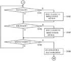
传感器控制器31还进行关于下行链路信号DS的发送是否中断的判定(步骤S183)。传感器控制器31在下行链路信号DS的接收结束时进行该判定,在该时点至下一下行链路信号DS的接收开始定时开始之前的期间存在规定时间以上的期间的情况下,判定为发送中断。The
在步骤S183中判定为发送未中断的情况下,传感器控制器31返回步骤S181而继续处理。另一方面,在判定为发送中断的情况下,将自身的动作模式切换为动作模式A(步骤S184),使基于方式A的上行链路信号的发送动作起动(步骤S185)。然后,判定基于该发送动作的发送次数是否达到规定次数(步骤S186)。When it is determined in step S183 that the transmission has not been interrupted, the
在步骤S186中判定为达到了规定次数的情况线下,传感器控制器31检测基于方式A的下行链路信号DS的接收开始定时的到来(步骤S187)。该定时是接收到基于方式A的上行链路信号US的触控笔2开始基于方式A的下行链路信号DS的发送的定时。传感器控制器31在接收开始定时到来的情况下,使基于方式A的下行链路信号DS的接收动作起动(步骤S188)。When it is determined in step S186 that the predetermined number of times has been reached, the
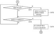
接下来,传感器控制器31通过在步骤S188中开始的接收动作来判定是否接收到下行链路信号DS(步骤S189),在判定为接收到的情况下,将自身的动作模式切换为动作模式A之后(步骤S192),使处理返回图22的步骤S161。由此,在触控笔2与传感器控制器31之间开始基于方式A的通信。Next, the
在步骤S186中判定为未达到规定次数的情况下,或者在步骤S189中判定为未接收到的情况下,传感器控制器31将自身的动作模式切换为动作模式C(步骤S190)。然后,判定在步骤S188中尝试了接收动作的次数是否达到规定次数(步骤S191),在判定为达到的情况下,使处理向图23的步骤S171转移。这相当于始终未接收到基于方式A的下行链路信号DS因此传感器控制器31放弃了基于方式A的通信的情况,在触控笔2与传感器控制器31之间开始基于方式C的通信。另一方面,在步骤S191中判定为未达到的情况下,传感器控制器31返回步骤S181而继续处理。When it is determined in step S186 that the predetermined number of times has not been reached, or when it is determined that it has not received in step S189, the
如以上说明所述,根据本实施方式的由触控笔2执行的方法,触控笔2也能够向触摸面3t的接触后立即使基于方式A的信号的接收动作起动。因此,能够缩短从与触摸面3t接触至触控笔2设定为动作模式A为止的时间。As described above, according to the method executed by the stylus pen 2 according to the present embodiment, the stylus pen 2 can also start the reception operation of the signal by the method A immediately after the touch of the stylus pen 2 on the
另外,根据本实施方式的由触控笔2和传感器控制器31执行的方法,即使触控笔2的动作模式是进行基于方式C的信号的单方向发送的动作模式C,通过掌握了触控笔2对应于方式A的传感器控制器31的指示(具体而言,基于方式A的上行链路信号US的发送),也能够将触控笔2的动作模式切换为动作模式A。因此,在触控笔2与传感器控制器31之间能够开始基于方式A的通信。In addition, according to the method executed by the stylus pen 2 and the
接下来,说明本发明的第三实施方式。本实施方式的触控笔2能够根据自身的动作模式而控制指示器26的显示内容,这一点与第一及第二实施方式的触控笔2不同。关于其他的点及传感器控制器31的结构,由于与第一或第二实施方式同样,因此以下着眼于不同点进行说明。Next, a third embodiment of the present invention will be described. The stylus 2 of the present embodiment is different from the stylus 2 of the first and second embodiments in that the display content of the
本实施方式的触控笔2的信号处理部24对指示器26进行控制,以根据如第一及第二实施方式中说明那样根据决定出的动作模式而进行不同的显示。即,对指示器26进行控制,在以发送基于第一方式的信号的第一动作模式进行动作的情况和以发送基于第二方式的信号的第二动作模式进行动作的情况下进行不同的显示。而且,对指示器26进行控制,以在决定是以第一动作模式进行动作还是以第二动作模式进行动作之前的阶段,即,以上述的未确定模式进行动作的情况下进行与第一及第二动作模式都不同的显示。由此,例如接收到基于第一方式的上行链路信号US时的信号处理部24的自身的动作模式成为第一动作模式,由此对指示器26进行控制以进行与第一动作模式对应的显示。The
如第一及第二实施方式中说明那样,如果触控笔2的动作模式在每次检测上行链路信号US或笔压时切换,则使用者难以掌握现在是以哪种动作模式动作。例如,在电子设备3与触控笔2虽然为相同动作模式但是未动作时等,无法掌握发生了什么情况。根据本实施方式的触控笔2,使用者通过确认指示器26,能够获知触控笔2(及传感器控制器31)现在是以哪种动作模式进行动作。As described in the first and second embodiments, if the operation mode of the stylus pen 2 is switched every time the uplink signal US or the pen pressure is detected, it is difficult for the user to know which operation mode is currently being operated. For example, when the
作为指示器26的具体的显示内容,可考虑各种内容。例如,若是在指示器26是能够以多色发光的发光二极管的情况下,则可考虑在未确定模式P时进行红色点亮,在第一动作模式时进行蓝色点亮,在第二动作模式时进行绿色点亮这样以按照各动作模式而以不同的颜色点亮的方式控制指示器26的显示内容。而且,若是指示器26是能够以单色发光的发光二极管的情况下,则可考虑在未确定模式P时以规定周期反复接通断开,在第一动作模式时,在切换为第一动作模式的定时以比上述规定周期短的间隔进行2次接通断开之后熄灭,在第二动作模式时,在切换为第二动作模式的定时仅进行1次接通断开之后熄灭这样将闪烁与熄灭组合来控制指示器26的显示内容。Various contents can be considered as specific display contents of the
以上,说明了本发明的优选实施方式,但是本发明不受这样的实施方式的任何限定,本发明能够当然在不脱离其主旨的范围内,以各种形态实施。The preferred embodiments of the present invention have been described above, but the present invention is not limited to such embodiments at all, and it goes without saying that the present invention can be implemented in various forms without departing from the gist of the present invention.
例如,在上述实施方式中,触控笔2通过电极21(图1)来接收上行链路信号US,但也可以通过例如BlueTooth(注册商标)等的另外的无线通信单元来接收上行链路信号US。而且,基于上行链路信号US(基于第一方式的信号)只要是触控笔2能够检测的信号即可,也包括利用了发送电极与接收电极的相互电容的执行手指触摸的检测的传感器控制器31将向发送电极供给的发送信号利用作为上行链路信号US的情况。For example, in the above-described embodiment, the stylus pen 2 receives the uplink signal US through the electrode 21 ( FIG. 1 ), but may receive the uplink signal through another wireless communication unit such as BlueTooth (registered trademark) or the like US. Further, the uplink signal US (signal based on the first method) only needs to be a signal that can be detected by the stylus pen 2, and also includes sensor control that performs detection of a finger touch by utilizing the mutual capacitance between the transmitting electrode and the receiving electrode. The
另外,在上述实施方式中,触控笔2及传感器控制器31在以某动作模式开始了动作之后,在未接收到应接收的信号的情况下立即返回未确定模式P(图9的步骤S26、图10的步骤S38、图12的步骤S66、图13的步骤S78、图19的步骤S126、图22的步骤S166、图23的步骤S174),但是可以不立即返回未确定模式P,在例如遍及规定次数未接收到的情况下返回未确定模式P。In addition, in the above-described embodiment, after the stylus pen 2 and the
在上述实施方式中,说明了将多个方式以最佳化的方式进行切换的情况,但是本发明当然也可以适用于从作为第二方式以旧的版本进行动作的动作模式切换为使用功能信息而以更新的版本进行动作的其他的动作模式的情况。In the above-described embodiment, the case where a plurality of modes are switched in an optimized manner has been described, but the present invention can of course be applied to switching from an operation mode that operates in an old version as the second mode to using function information On the other hand, in the case of other operation modes that operate in the updated version.
符号说明Symbol Description
1 位置检测系统1 Position detection system
2 触控笔2 Stylus
3 电子设备3 Electronics
3t 触摸面3t touch surface
20 芯体20 cores
21 电极21 electrodes
22 笔压检测部22 Pen pressure detection section
23 开关23 switches
24 信号处理部24 Signal Processing Section
25 电源25 Power
26 指示器26 Indicators
30 传感器30 sensors
30X、30Y 线状电极30X, 30Y Wire Electrodes
31 传感器控制器31 Sensor Controller
32 系统控制器32 System Controller
40 选择部40 Selection Section
41x、41y 导体选择电路41x, 41y conductor selection circuit
44x、44y 开关44x, 44y switches
50 接收部50 Receiving Department
51 放大电路51 Amplifier circuit
52 检波电路52 Detection circuit
53 AD变换器53 AD converter
60 发送部60 Sending Department
61 图案供给部61 Pattern Supply Section
62 开关62 switches
63 扩散处理部63 Diffusion Treatment Department
64 代码列保持部64 Code Column Holder
65 发送保护部65 Transmission Protection Section
70 逻辑部70 Logic Department
80 MCU80 MCUs
DS 下行链路信号DS downlink signal
PD1 第一下笔PD1 first pen
PD2 第二下笔PD2 second stroke
SR 传感范围SR sensing range
US 上行链路信号。US uplink signal.
Claims (6)
Priority Applications (1)
| Application Number | Priority Date | Filing Date | Title |
|---|---|---|---|
| CN202210662042.6ACN115185387A (en) | 2016-07-01 | 2016-07-01 | Active stylus |
Applications Claiming Priority (3)
| Application Number | Priority Date | Filing Date | Title |
|---|---|---|---|
| CN201680087279.9ACN109416595B (en) | 2016-07-01 | 2016-07-01 | Method executed by dual stylus and dual controller, and dual stylus |
| CN202210662042.6ACN115185387A (en) | 2016-07-01 | 2016-07-01 | Active stylus |
| PCT/JP2016/069705WO2018003122A1 (en) | 2016-07-01 | 2016-07-01 | Method executed by stylus, method executed by dual stylus and dual controller, and dual stylus |
Related Parent Applications (1)
| Application Number | Title | Priority Date | Filing Date |
|---|---|---|---|
| CN201680087279.9ADivisionCN109416595B (en) | 2016-07-01 | 2016-07-01 | Method executed by dual stylus and dual controller, and dual stylus |
Publications (1)
| Publication Number | Publication Date |
|---|---|
| CN115185387Atrue CN115185387A (en) | 2022-10-14 |
Family
ID=60787266
Family Applications (2)
| Application Number | Title | Priority Date | Filing Date |
|---|---|---|---|
| CN202210662042.6APendingCN115185387A (en) | 2016-07-01 | 2016-07-01 | Active stylus |
| CN201680087279.9AActiveCN109416595B (en) | 2016-07-01 | 2016-07-01 | Method executed by dual stylus and dual controller, and dual stylus |
Family Applications After (1)
| Application Number | Title | Priority Date | Filing Date |
|---|---|---|---|
| CN201680087279.9AActiveCN109416595B (en) | 2016-07-01 | 2016-07-01 | Method executed by dual stylus and dual controller, and dual stylus |
Country Status (5)
| Country | Link |
|---|---|
| US (2) | US10949035B2 (en) |
| JP (1) | JP6280297B1 (en) |
| CN (2) | CN115185387A (en) |
| TW (1) | TWI752020B (en) |
| WO (1) | WO2018003122A1 (en) |
Families Citing this family (10)
| Publication number | Priority date | Publication date | Assignee | Title |
|---|---|---|---|---|
| KR102346206B1 (en) | 2014-01-22 | 2022-01-03 | 가부시키가이샤 와코무 | Position indicator, position detection device, position detection circuit, and position detection method |
| CN118625956A (en)* | 2019-03-01 | 2024-09-10 | 株式会社和冠 | Sensor controller and pen |
| JP7329938B2 (en)* | 2019-03-19 | 2023-08-21 | 株式会社ワコム | Information processing system, position indicator, and method for controlling movement of displayed object displayed on display screen of information processing device |
| KR102738420B1 (en)* | 2019-09-20 | 2024-12-04 | 주식회사 하이딥 | Stylus pen, touch apparatus, and touch system |
| KR20210070458A (en)* | 2019-12-04 | 2021-06-15 | 삼성디스플레이 주식회사 | Display device and portable device comprising teereof |
| WO2021179167A1 (en)* | 2020-03-10 | 2021-09-16 | 深圳市汇顶科技股份有限公司 | Wireless communication method, active pen, touch screen, electronic device, and communication system |
| JP7482706B2 (en)* | 2020-07-08 | 2024-05-14 | 株式会社ワコム | Method performed by a stylus and sensor controller, stylus and sensor controller |
| KR20220091700A (en)* | 2020-12-23 | 2022-07-01 | 삼성디스플레이 주식회사 | Electronic device |
| JP7644629B2 (en)* | 2021-03-19 | 2025-03-12 | 株式会社ワコム | Active pen, sensor controller, and position detection device |
| CN116249956A (en)* | 2021-09-15 | 2023-06-09 | 株式会社和冠 | System comprising a pen and a touch controller, method performed by a pen, pen and touch controller |
Citations (3)
| Publication number | Priority date | Publication date | Assignee | Title |
|---|---|---|---|---|
| US20120105361A1 (en)* | 2010-10-28 | 2012-05-03 | Cypress Semiconductor Corporation | Capacitive stylus with palm rejection |
| US20160077655A1 (en)* | 2014-09-17 | 2016-03-17 | Wacom Co., Ltd. | Sensor signal processing circuit and sensor signal processing method |
| US20160098124A1 (en)* | 2013-06-07 | 2016-04-07 | Sharp Kabushiki Kaisha | Touch panel system and electronic device |
Family Cites Families (19)
| Publication number | Priority date | Publication date | Assignee | Title |
|---|---|---|---|---|
| JPH04353918A (en) | 1991-05-31 | 1992-12-08 | Toshiba Corp | Coordinate detection instructing device |
| AU772145B2 (en)* | 1999-10-25 | 2004-04-08 | Silverbrook Research Pty Ltd | Electronically controllable pen |
| US8536471B2 (en) | 2008-08-25 | 2013-09-17 | N-Trig Ltd. | Pressure sensitive stylus for a digitizer |
| JP5345050B2 (en) | 2009-12-25 | 2013-11-20 | 株式会社ワコム | Indicator, position detection device and position detection method |
| US9122322B2 (en)* | 2011-03-17 | 2015-09-01 | Microsoft Technology Licensing, Llc | Interacting tips for a digitizer stylus |
| TWI442301B (en)* | 2011-09-23 | 2014-06-21 | A dual mode tablet and the method of the signal detect and the switch mode | |
| KR20130141837A (en)* | 2012-06-18 | 2013-12-27 | 삼성전자주식회사 | Device and method for changing mode in terminal |
| JP5984259B2 (en) | 2012-09-20 | 2016-09-06 | 株式会社ワコム | Position detection device |
| EP2741170A1 (en)* | 2012-12-10 | 2014-06-11 | BlackBerry Limited | Active stylus force sensing mechanism for generating a wakeup interrupt to the stylus controller |
| KR102346206B1 (en) | 2014-01-22 | 2022-01-03 | 가부시키가이샤 와코무 | Position indicator, position detection device, position detection circuit, and position detection method |
| US9703946B2 (en)* | 2014-03-31 | 2017-07-11 | Stmicroelectronics Asia Pacific Pte Ltd | Secure pairing method, circuit and system for an intelligent input device and an electronic device |
| JP5723499B1 (en)* | 2014-10-24 | 2015-05-27 | 株式会社ワコム | Sending electronic pen |
| KR102551801B1 (en)* | 2014-11-17 | 2023-07-06 | 가부시키가이샤 와코무 | Position indicator |
| CN105718076B (en)* | 2014-12-03 | 2019-03-01 | 矽统科技股份有限公司 | Active stylus and signal transmission method of active stylus and touch panel |
| US9383839B1 (en)* | 2014-12-08 | 2016-07-05 | Amazon Technologies, Inc. | Configuration of a profile associated with a stylus |
| US9575573B2 (en)* | 2014-12-18 | 2017-02-21 | Apple Inc. | Stylus with touch sensor |
| CN107111388B (en)* | 2015-01-04 | 2020-06-05 | 微软技术许可有限责任公司 | Method and apparatus for communicating with a universal stylus of a digitizer |
| CN107850955B (en) | 2015-08-21 | 2021-12-07 | 株式会社和冠 | Touch pen and color information transmission method |
| US20170315631A1 (en)* | 2016-04-29 | 2017-11-02 | Qualcomm Incorporated | System and method for multimode stylus |
- 2016
- 2016-07-01CNCN202210662042.6Apatent/CN115185387A/enactivePending
- 2016-07-01CNCN201680087279.9Apatent/CN109416595B/enactiveActive
- 2016-07-01JPJP2017555410Apatent/JP6280297B1/enactiveActive
- 2016-07-01WOPCT/JP2016/069705patent/WO2018003122A1/ennot_activeCeased
- 2017
- 2017-04-17TWTW106112801Apatent/TWI752020B/enactive
- 2018
- 2018-12-20USUS16/227,783patent/US10949035B2/enactiveActive
- 2021
- 2021-03-15USUS17/201,613patent/US20210200377A1/ennot_activeAbandoned
Patent Citations (3)
| Publication number | Priority date | Publication date | Assignee | Title |
|---|---|---|---|---|
| US20120105361A1 (en)* | 2010-10-28 | 2012-05-03 | Cypress Semiconductor Corporation | Capacitive stylus with palm rejection |
| US20160098124A1 (en)* | 2013-06-07 | 2016-04-07 | Sharp Kabushiki Kaisha | Touch panel system and electronic device |
| US20160077655A1 (en)* | 2014-09-17 | 2016-03-17 | Wacom Co., Ltd. | Sensor signal processing circuit and sensor signal processing method |
Also Published As
| Publication number | Publication date |
|---|---|
| US20190121455A1 (en) | 2019-04-25 |
| WO2018003122A1 (en) | 2018-01-04 |
| CN109416595A (en) | 2019-03-01 |
| TW201804295A (en) | 2018-02-01 |
| US10949035B2 (en) | 2021-03-16 |
| JP6280297B1 (en) | 2018-02-14 |
| US20210200377A1 (en) | 2021-07-01 |
| CN109416595B (en) | 2022-07-05 |
| JPWO2018003122A1 (en) | 2018-06-28 |
| TWI752020B (en) | 2022-01-11 |
Similar Documents
| Publication | Publication Date | Title |
|---|---|---|
| CN109416595B (en) | Method executed by dual stylus and dual controller, and dual stylus | |
| JP7235685B2 (en) | Sensor controller and active pen | |
| CN109643172A (en) | Touch control pen and sensor controller | |
| WO2016186191A1 (en) | Active stylus | |
| WO2020017477A1 (en) | Sensor controller, active pen, and communication method | |
| WO2018020598A1 (en) | Stylus and sensor controller | |
| CN107533384B (en) | Method using active stylus and sensor controller, and active stylus | |
| CN107850951A (en) | Method, stylus and the sensor controller of stylus detection sensor controller | |
| TWI719175B (en) | Analog circuit, position indicator and system | |
| KR102534115B1 (en) | Method using active stylus and sensor controller, sensor controller, and active stylus | |
| JP7604082B2 (en) | Integrated circuits for pens | |
| JP6710244B2 (en) | Stylus and method performed by the stylus | |
| KR100726425B1 (en) | Wireless communication device, wireless communication system using same and control method thereof | |
| JP2025138801A (en) | Pen, system including pen and touch controller | |
| JP6867535B2 (en) | Dual controllers and dual styli and how they are performed | |
| JP6363807B2 (en) | Active stylus | |
| JP7570380B2 (en) | stylus | |
| CN115113742A (en) | Active pen, sensor controller and position detection device | |
| JP7159411B2 (en) | Sensor controller, computer implemented method and electronics | |
| TW202522190A (en) | Sensor controller and stylus |
Legal Events
| Date | Code | Title | Description |
|---|---|---|---|
| PB01 | Publication | ||
| PB01 | Publication | ||
| SE01 | Entry into force of request for substantive examination | ||
| SE01 | Entry into force of request for substantive examination |