CN115185236A - A tool path planning method to avoid tool overcut - Google Patents
A tool path planning method to avoid tool overcutDownload PDFInfo
- Publication number
- CN115185236A CN115185236ACN202210609329.2ACN202210609329ACN115185236ACN 115185236 ACN115185236 ACN 115185236ACN 202210609329 ACN202210609329 ACN 202210609329ACN 115185236 ACN115185236 ACN 115185236A
- Authority
- CN
- China
- Prior art keywords
- tool
- cutter
- point
- small line
- tool path
- Prior art date
- Legal status (The legal status is an assumption and is not a legal conclusion. Google has not performed a legal analysis and makes no representation as to the accuracy of the status listed.)
- Pending
Links
Images


Classifications
- G—PHYSICS
- G05—CONTROLLING; REGULATING
- G05B—CONTROL OR REGULATING SYSTEMS IN GENERAL; FUNCTIONAL ELEMENTS OF SUCH SYSTEMS; MONITORING OR TESTING ARRANGEMENTS FOR SUCH SYSTEMS OR ELEMENTS
- G05B19/00—Programme-control systems
- G05B19/02—Programme-control systems electric
- G05B19/18—Numerical control [NC], i.e. automatically operating machines, in particular machine tools, e.g. in a manufacturing environment, so as to execute positioning, movement or co-ordinated operations by means of programme data in numerical form
- G05B19/41—Numerical control [NC], i.e. automatically operating machines, in particular machine tools, e.g. in a manufacturing environment, so as to execute positioning, movement or co-ordinated operations by means of programme data in numerical form characterised by interpolation, e.g. the computation of intermediate points between programmed end points to define the path to be followed and the rate of travel along that path
- G05B19/4103—Digital interpolation
- G—PHYSICS
- G05—CONTROLLING; REGULATING
- G05B—CONTROL OR REGULATING SYSTEMS IN GENERAL; FUNCTIONAL ELEMENTS OF SUCH SYSTEMS; MONITORING OR TESTING ARRANGEMENTS FOR SUCH SYSTEMS OR ELEMENTS
- G05B2219/00—Program-control systems
- G05B2219/30—Nc systems
- G05B2219/34—Director, elements to supervisory
- G05B2219/34153—Linear interpolation
- Y—GENERAL TAGGING OF NEW TECHNOLOGICAL DEVELOPMENTS; GENERAL TAGGING OF CROSS-SECTIONAL TECHNOLOGIES SPANNING OVER SEVERAL SECTIONS OF THE IPC; TECHNICAL SUBJECTS COVERED BY FORMER USPC CROSS-REFERENCE ART COLLECTIONS [XRACs] AND DIGESTS
- Y02—TECHNOLOGIES OR APPLICATIONS FOR MITIGATION OR ADAPTATION AGAINST CLIMATE CHANGE
- Y02P—CLIMATE CHANGE MITIGATION TECHNOLOGIES IN THE PRODUCTION OR PROCESSING OF GOODS
- Y02P90/00—Enabling technologies with a potential contribution to greenhouse gas [GHG] emissions mitigation
- Y02P90/02—Total factory control, e.g. smart factories, flexible manufacturing systems [FMS] or integrated manufacturing systems [IMS]
Landscapes
- Engineering & Computer Science (AREA)
- Computing Systems (AREA)
- Theoretical Computer Science (AREA)
- Human Computer Interaction (AREA)
- Manufacturing & Machinery (AREA)
- Physics & Mathematics (AREA)
- General Physics & Mathematics (AREA)
- Automation & Control Theory (AREA)
- Numerical Control (AREA)
Abstract
Description
Translated fromChinese技术领域technical field
本发明涉及数控铣削加工的技术领域,尤其涉及一种避免刀具过切的刀具轨迹规划方法。The invention relates to the technical field of numerical control milling, in particular to a tool path planning method for avoiding tool overcut.
背景技术Background technique
目前,在航空航天、汽车和模具等制造业中,存在很多具有复杂曲面外形的零件,这类零件的生产制造往往是整个生产过程中的难点。随着计算机技术的发展,数控技术为这类零件的生产制造提供了更好的选择。数控加工中,加工程序的好坏直接影响了零件的加工效果和加工效率,手动人工数控编程、程序试切验证等传统制造工艺已经无法满足快速发展的工业需求。At present, in aerospace, automobile and mold manufacturing industries, there are many parts with complex curved shapes, and the production of such parts is often a difficult point in the entire production process. With the development of computer technology, numerical control technology provides a better choice for the manufacture of such parts. In CNC machining, the quality of the processing program directly affects the processing effect and processing efficiency of the parts. Traditional manufacturing processes such as manual manual CNC programming and program trial cutting verification have been unable to meet the needs of the rapidly developing industry.
计算机辅助制造(Computer Aided Manufacturing,简称CAM)技术是数控技术的关键环节,CAM软件根据零件的几何信息,自动进行刀具轨迹的规划和加工程序的生成。对于复杂曲面的数控加工必须借助CAM软件,因此,CAM软件对当今制造业的发展非常重要。Computer Aided Manufacturing (CAM for short) technology is the key link of CNC technology. CAM software can automatically plan the tool path and generate the machining program according to the geometric information of the part. For CNC machining of complex surfaces, CAM software must be used. Therefore, CAM software is very important to the development of today's manufacturing industry.
CAM技术中,刀具轨迹规划是其中的重要环节。对于三轴数控加工中,在理想情况下,刀具只需以恒定姿态沿工件轮廓进行切削,即可加工出工件的复杂曲面,然而由于刀具半径的存在,刀具直接沿工件表面轮廓进行切削可能与工件表面存在局部过切。In CAM technology, tool path planning is an important part of it. For three-axis CNC machining, ideally, the tool only needs to cut along the contour of the workpiece with a constant attitude to process the complex surface of the workpiece. However, due to the existence of the tool radius, cutting the tool directly along the contour of the workpiece surface may be different from that of the workpiece. There is local overcut on the workpiece surface.
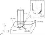
如图1所示,是刀具与工件表面局部过切示意图。为便于确定刀具在工件坐标系中的位置,通常选取刀具一固定位置作为控制刀具运动的驱动点,该点被称之为刀位点。刀具刀位点的轨迹即为刀具轨迹。对于三轴数控加工(即刀具仅能进行XYZ三轴平移运动,而不能进行姿态变化),刀轴方向均为Z轴正方向。以曲面加工中常用的球刀为例,以球刀刀尖作为刀位点。若直接驱动刀具沿刀具轨迹进行加工,因刀具半径的存在,刀具在点P位置时与工件表面产生了干涉,带来了局部过切,从而影响工件表面的面形精度与质量。As shown in Figure 1, it is a schematic diagram of partial overcut between the tool and the workpiece surface. In order to determine the position of the tool in the workpiece coordinate system, a fixed position of the tool is usually selected as the driving point for controlling the movement of the tool, which is called the tool position point. The path of the tool position point is the tool path. For three-axis CNC machining (that is, the tool can only perform XYZ three-axis translation movement, but cannot perform attitude changes), the direction of the tool axis is the positive direction of the Z axis. Taking the ball cutter commonly used in surface machining as an example, the tip of the ball cutter is used as the tool position point. If the tool is directly driven to process along the tool path, due to the existence of the tool radius, the tool interferes with the workpiece surface at the point P position, resulting in local overcut, thus affecting the surface shape accuracy and quality of the workpiece surface.
现有技术中,避免刀具与工件表面发生局部过切的方法很多,常见的方法一是通过旋转刀轴角度,以避免过切(例如CN201310467081.1公开的“一种基于刀具姿态渐变的加工误差均布方法”);二是通过半径补偿避免过切(例如CN201810495721.2公开的“一种工业机器人铣削复杂曲面无过切刀具路径插补方法”)。然而对于三轴数控加工来说,由于刀具不能进行姿态变化,因此不能通过规划刀轴角度的方法避免刀具过切。而半径补偿方法只适用于球头铣刀,缺乏通用性。In the prior art, there are many methods to avoid local overcut between the tool and the workpiece surface. One common method is to rotate the angle of the tool axis to avoid overcut (for example, "a machining error based on the gradual change of the tool attitude" disclosed in CN201310467081.1. The second is to avoid overcutting through radius compensation (for example, "An industrial robot milling complex curved surface without overcutting tool path interpolation method" disclosed in CN201810495721.2). However, for three-axis CNC machining, since the tool cannot change the attitude, it is impossible to avoid the tool overcut by planning the angle of the tool axis. The radius compensation method is only suitable for ball end milling cutters and lacks universality.
因此,为保证加工工件表面的质量,避免刀具与工件表面的局部过切,必须寻求一种计算方法简单、通用性好的刀具轨迹规划方法。Therefore, in order to ensure the quality of the workpiece surface and avoid the partial overcut between the tool and the workpiece surface, it is necessary to find a tool path planning method with a simple calculation method and good versatility.
发明内容SUMMARY OF THE INVENTION
本发明所要解决的技术问题在于提供一种避免刀具过切的刀具轨迹规划方法,其对刀具轨迹的每一点进行刀具过切判断,并对刀具轨迹进行优化,从而避免刀具过切。The technical problem to be solved by the present invention is to provide a tool path planning method for avoiding tool overcut, which judges tool overcut at each point of the tool path, and optimizes the tool path, thereby avoiding tool overcut.
为解决上述技术问题,本发明的技术解决方案是:For solving the above-mentioned technical problems, the technical solution of the present invention is:
一种避免刀具过切的刀具轨迹规划方法,包括如下步骤:A tool path planning method for avoiding tool overcut, comprising the following steps:
一、对待加工工件曲面进行三维建模;1. 3D modeling of the surface of the workpiece to be processed;
二、对三维模型进行切片处理,以切片轮廓作为初始刀具轨迹;2. Slice the 3D model, and use the slice outline as the initial tool path;
三、对三维模型进行离散处理,从而得到待加工曲面表面的若干离散特征点;3. Perform discrete processing on the three-dimensional model to obtain several discrete feature points of the surface to be processed;
四、建立刀具模型;4. Establish tool model;
五、根据加工曲面三维模型的离散数据优化刀具轨迹,获得优化刀具轨迹;即判断刀具在初始刀具轨迹上某一位置时,刀具内部是否存在工件表面离散特征点,如果存在,则将刀具进行沿刀轴方向的抬升,直至刀具内部不存在离散特征点;如果刀具内部不存在工件表面离散特征点,则保持原轨迹不动;对初始刀具轨迹上的所有刀位点进行计算,获得优化后的刀具轨迹。5. Optimize the tool path according to the discrete data of the three-dimensional model of the machined surface to obtain the optimized tool path; that is to judge whether there are discrete feature points on the workpiece surface inside the tool when the tool is at a certain position on the initial tool path, and if so, move the tool along the tool path. Raise the tool axis direction until there are no discrete feature points inside the tool; if there are no discrete feature points on the workpiece surface inside the tool, keep the original path unchanged; calculate all the tool position points on the initial tool path to obtain the optimized tool path.
优选的,所述步骤五中,刀具抬升距离的计算方法为:以刀具内部其中一个离散特征点为起点,沿刀轴反方向的射线与刀具底面的交点,并计算该射线起点到交点的距离,刀具沿刀轴方向抬升该距离即可避免刀具对该离散特征点的过切;对于刀具内部的其他特征点均按此方法计算抬升距离,并取最大值作为刀具在此处的最终抬升距离。Preferably, in the
优选的,所述步骤五中,刀具抬升距离的计算方法为:首先将刀具内部的所有特征点均绕刀轴旋转至一固定平面;然后计算出刀具在这一固定平面上的轮廓曲线;最后在该固定平面上计算以特征点为起点沿刀轴反方向的射线与该固定平面刀具轮廓曲线的交点,并计算起点到交点的距离;所有特征点的所述距离中的最大值作为刀具在此处的最终抬升距离。Preferably, in the
优选的,所述步骤一采用三维建模软件进行建模,并转成STL模型格式;所述步骤二获得切片轮廓的方法包括如下步骤:Preferably, in the first step, three-dimensional modeling software is used for modeling, and it is converted into an STL model format; the method for obtaining the slice profile in the second step includes the following steps:
(1)首先将STL模型中每个三角面片与切平面求交得到的两个交点组成一条小线段,则STL模型中若干三角面片与切平面求交可得若干条小线段;(1) First, two intersection points obtained by intersecting each triangular facet and the tangent plane in the STL model form a small line segment, then several small line segments can be obtained by intersecting several triangular facets and the tangent plane in the STL model;
(2)以与同一切平面求交得到的若干小线段中某一小线段为起始小线段,以该起始小线段的一端点为公共点,在剩余小线段中搜索该公共点所在的另外一条小线段,该小线段即为起始小线段的相邻小线段;然后再以第二条小线段的非公共点端点为新公共点,在剩余小线段中继续搜索新公共点所在的另外一条小线段;重复这个过程,即可实现对无序小线段的排序,进而实现对该切平面切片交点的排序;(2) Take a small line segment among several small line segments obtained by intersecting with the same tangent plane as the initial small line segment, and take an endpoint of the initial small line segment as the common point, and search the remaining small line segments for the location where the common point is located. Another small line segment, this small line segment is the adjacent small line segment of the initial small line segment; and then take the non-common point endpoint of the second small line segment as the new common point, and continue to search for the new common point in the remaining small line segments. Another small line segment; repeating this process, the ordering of the disordered small line segments can be realized, and then the ordering of the intersection points of the tangent plane slices can be realized;
(3)确定起始小线段,对于切片轮廓为封闭二维轮廓的模型,起始小线段可为其中的任意一条小线段;对于切片轮廓为非封闭二维轮廓的模型,起始小线段必须在其一端点。(3) Determine the starting small line segment. For the model whose slice outline is a closed two-dimensional outline, the starting small line segment can be any one of them; for the model whose slice outline is a non-closed two-dimensional outline, the starting small line segment must be at one of its endpoints.
优选的,所述步骤一采用三维建模软件进行建模,并转成STL模型格式;所述步骤三对STL模型进行离散处理的方法为:首先,确定三角面片三条边中的最长边,过最长边外一点,作最长边的垂线,将原三角面片分为两个直角三角面片;再将直角三角面片的一条直角边进行等间距离散,将该直角边离散点沿另一条直角边方向进行等距偏移,直至偏移点在直角三角面片外部;这个过程中的偏移点即为该直角三角面片的离散特征点,对另一直角三角面片采用同样的方法进行离散;如此即完成了一个三角面片的离散,对STL模型中所有三角面片重复上述过程,即可完成整个STL模型的离散。Preferably, in the first step, three-dimensional modeling software is used for modeling, and it is converted into an STL model format; the method for discretely processing the STL model in the third step is: first, determine the longest side of the three sides of the triangular patch , pass a point outside the longest side, make the vertical line of the longest side, and divide the original triangular patch into two right-angled triangular patches; The point is offset equidistantly along the direction of another right-angled side until the offset point is outside the right-angled triangle patch; the offset point in this process is the discrete feature point of the right-angled triangle patch, and the offset point in the process is the discrete feature point of the right-angled triangle patch. The same method is used for discretization; in this way, the discretization of a triangular patch is completed, and the above process is repeated for all triangular patches in the STL model to complete the discretization of the entire STL model.
优选的,所述步骤五中,在对刀具轨迹进行优化前,先对刀具轨迹进行等距插值,插值点为所述的刀位点,具体步骤为:Preferably, in the
(1)以刀具轨迹的起点为圆心,以设定步长为半径作圆,计算刀具轨迹中与该圆存在交点的相邻两点连线,并以交点为分割点,将刀具轨迹分为前后两段;(1) Take the starting point of the tool path as the center of the circle and the set step size as the radius to make a circle, calculate the line connecting the two adjacent points in the tool path that intersect the circle, and take the intersection point as the dividing point to divide the tool path into two parts. two paragraphs before and after;
(2)以后面一段刀具轨迹的起点为圆心,继续以设定步长为半径作圆,计算刀具轨迹中与该圆存在交点的相邻两点连线,然后计算圆与两点连线的交点坐标,并以该坐标为分割点,将刀具轨迹分为前后两段;(2) Take the starting point of the following tool path as the center of the circle, continue to make a circle with the set step size as the radius, calculate the line connecting the two adjacent points that intersect the circle in the tool path, and then calculate the distance between the circle and the line connecting the two points. The coordinate of the intersection point, and the coordinate is used as the dividing point to divide the tool path into two sections;
(3)重复以上步骤,直至在以后面一段刀具轨迹的起点为圆心作半径为设定步长的圆时,刀具轨迹中无相邻两点连线与该圆存在交点。(3) Repeat the above steps until the circle with the radius of the set step is made with the starting point of the following tool path as the center, and there is no intersection between the line connecting two adjacent points in the tool path and the circle.
采用上述方案后,本发明将工件表面进行离散,得到能表达工件表面几何特征的空间离散特征点,此时,刀具在某一位置时与工件表面发生过切的局部特征,可简化为刀具在该位置时刀具内部存在的工件表面离散特征点;然后将刀具进行沿刀轴方向的抬升,直至刀具内部不存在离散特征点,如此即可避免刀具在此处的过切,优化刀具轨迹。该方法通用性好,实用性强。After adopting the above scheme, the present invention discretizes the workpiece surface to obtain spatial discrete feature points that can express the geometrical features of the workpiece surface. At this time, the local feature that the tool overcuts the workpiece surface at a certain position can be simplified as the tool at a certain position. At this position, there are discrete feature points on the workpiece surface that exist inside the tool; then the tool is lifted along the tool axis until there are no discrete feature points inside the tool, so that overcutting of the tool here can be avoided and the tool path can be optimized. The method has good versatility and practicability.
附图说明Description of drawings
图1是数控铣削加工曲面时刀具与工件表面局部过切示意图;Figure 1 is a schematic diagram of the partial overcut between the tool and the workpiece surface when the surface is processed by CNC milling;
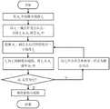
图2是本发明的流程图;Fig. 2 is the flow chart of the present invention;
图3是本发明切片轮廓构建示意图;3 is a schematic diagram of the construction of slice contours of the present invention;
图4是本发明切片轮廓构建流程图;Fig. 4 is the construction flow chart of slice outline of the present invention;
图5是本发明所述三角面片离散示意图;Fig. 5 is the discrete schematic diagram of the triangular facet of the present invention;
图6是本发明所述离散方法实例示意图;6 is a schematic diagram of an example of the discrete method of the present invention;
图7是常用刀具模型示意图;Figure 7 is a schematic diagram of a commonly used tool model;
图8是常用刀具的轮廓曲线模型示意图;Figure 8 is a schematic diagram of the profile curve model of a commonly used tool;
图9是本发明所述刀具局部过切简化模型示意图;9 is a schematic diagram of a simplified model of partial overcutting of the cutter according to the present invention;
图10是本发明所述刀具内部的特征点绕刀轴旋转示意图;Figure 10 is a schematic diagram of the rotation of the feature point inside the tool according to the present invention around the tool axis;
图11是本发明所述刀具抬升至无过切位置示意图;FIG. 11 is a schematic diagram of the present invention being lifted to a position without overcutting;
图12是本发明所述刀具轨迹优化前后实例示意图。FIG. 12 is a schematic diagram of an example before and after the tool path optimization according to the present invention.
图13是刀具在刀具轨迹中相邻两点之间过长时运动刀具局部过切示意图;Figure 13 is a schematic diagram of the partial overcut of the moving tool when the tool is too long between two adjacent points in the tool path;
图14为本发明所述对刀具轨迹的等距插值示意图;14 is a schematic diagram of the isometric interpolation of the tool path according to the present invention;
图15为本发明所述刀具轨迹的等距插值前后对比实例示意图。FIG. 15 is a schematic diagram of a comparative example before and after the isometric interpolation of the tool path according to the present invention.
具体实施方式Detailed ways
下面结合附图和具体实施例对本发明作进一步详述。The present invention will be described in further detail below with reference to the accompanying drawings and specific embodiments.
本发明所揭示的是一种避免刀具过切的刀具轨迹规划方法:首先,对加工工件进行三维建模,并对三维模型进行切片处理,各切片与工件表面的切片轮廓为初始刀具轨迹;之后,对加工工件三维模型进行离散处理,得到加工工件表面的若干离散特征点;然后,判断刀具在初始刀具轨迹上某一位置时,刀具内部是否存在工件表面离散特征点,如果存在,则将刀具进行沿刀轴方向的抬升,直至刀具内部不存在离散特征点,如此即可避免刀具在此处的过切;如果刀具内部不存在工件表面离散特征点,则保持原轨迹不动;对初始刀具轨迹上的所有刀位点进行计算,获得优化后的刀具轨迹。The invention discloses a tool path planning method for avoiding tool overcut: first, three-dimensional modeling is performed on the workpiece, and the three-dimensional model is sliced, and the slice contour of each slice and the surface of the workpiece is the initial tool path; then , perform discrete processing on the three-dimensional model of the workpiece to obtain a number of discrete feature points on the workpiece surface; then, determine whether there are discrete feature points on the workpiece surface inside the tool when the tool is at a certain position on the initial tool path, and if so, the tool Lift along the tool axis direction until there are no discrete feature points inside the tool, so as to avoid overcutting of the tool here; if there are no discrete feature points on the workpiece surface inside the tool, keep the original trajectory; All tool positions on the path are calculated to obtain the optimized tool path.
如图2所示,为本发明刀具规划方法的流程图,其具体可以包括如下步骤:As shown in Figure 2, it is a flowchart of the tool planning method of the present invention, which may specifically include the following steps:
一、对待加工工件曲面进行三维建模。1. 3D modeling of the surface of the workpiece to be processed.
待加工工件的三维模型建立可以采用多种方法。目前复杂曲面的表达形式主要有参数模型和STL模型两种。STL模型采用许多空间小三角形来逼近复杂曲面,具有数据格式灵活、易于存储、读取与显示方便、通用性高等优点,被广泛应用于3D打印和数控加工刀具轨迹规划中。本发明则以STL模型为例。Various methods can be used to establish the 3D model of the workpiece to be processed. At present, there are two main forms of expression of complex surfaces: parametric model and STL model. The STL model uses many small space triangles to approximate complex surfaces. It has the advantages of flexible data format, easy storage, convenient reading and display, and high versatility. It is widely used in 3D printing and CNC machining tool path planning. The present invention takes the STL model as an example.
二、对三维模型进行切片处理,以切片轮廓作为初始刀具轨迹。2. Slice the 3D model, and use the slice outline as the initial tool path.
对三维模型进行切片处理,即通过一系列相互平行的切平面与三维模型进行求交,而得到的交线即为切片轮廓,以该切片轮廓作为初始刀具轨迹。Slicing the 3D model, that is, intersecting the 3D model through a series of parallel tangent planes, and the obtained intersection line is the slice outline, and the slice outline is used as the initial tool path.
对于STL模型来说,STL模型切片是通过一系列相互平行的切平面与模型中三角面片进行求交,并将得到的交点连成能表达原模型几何外形的切片轮廓过程。由于STL模型是通过对模型表面进行三角化处理或由点云数据生成的,因此其中的三角面片为无序三角面片,在计算出切平面与三角面片的交点后无法直接进行切片轮廓的构建。所以需要设计算法获取切片轮廓。现有技术中,获取切片轮廓的方法很多,例如CN202110100621.7公开的“一种基于相交边映射的STL模型3D打印切片方法”。For the STL model, the STL model slicing is a process of intersecting the triangular facets in the model through a series of parallel tangent planes, and connecting the obtained intersection points into a slice outline process that can express the geometric shape of the original model. Since the STL model is generated by triangulating the surface of the model or generated from point cloud data, the triangular patches in it are disordered triangular patches, and the slice outline cannot be directly performed after calculating the intersection of the tangent plane and the triangular patch. 's build. Therefore, an algorithm needs to be designed to obtain the slice contour. In the prior art, there are many methods for obtaining slice contours, such as "A STL Model 3D Printing Slicing Method Based on Intersection Edge Mapping" disclosed in CN202110100621.7.
而本发明实施例,根据STL模型中相邻三角面片存在公共边,在与切平面求交后得到的两条小线段存在公共点这一特性,通过搜索相邻小线段之间的公共点,将若干无序的小线段进行排序从而得到能表达原模型几何特征的切片轮廓。该方法避免了拓扑关系重建所带来的算法复杂度,其具体步骤如下:However, in the embodiment of the present invention, according to the characteristic that the adjacent triangular facets in the STL model have common edges, and the two small line segments obtained after intersecting with the tangent plane have a common point, the common point between adjacent small line segments is searched by searching for the common point. , sort a number of disordered small line segments to obtain slice outlines that can express the geometric features of the original model. This method avoids the algorithmic complexity brought by the reconstruction of topological relations. The specific steps are as follows:
(1)首先将每个三角面片与切平面求交得到的两个交点组成一条小线段,则STL模型中若干三角面片与切平面求交可得若干条小线段。其中:交于三角面片的一顶点和交于三顶点的情况除外;若交于两顶点,则表示在该处切平面交于两三角面片的公共边,只保留一条边即可。(1) First, the two intersection points obtained by intersecting each triangular facet with the tangent plane form a small line segment, then several small line segments can be obtained by intersecting several triangular facets and the tangent plane in the STL model. Among them: except for the case where it intersects at one vertex of a triangular facet and at three vertices; if it intersects at two vertices, it means that the tangent plane intersects the common edge of the two triangular faces at that point, and only one edge is left.
由于STL模型文件中储存有每个三角面片的三个顶点坐标,因此可以根据空间直线与平面的求交公式进行交点的坐标求解。Since the three vertex coordinates of each triangular facet are stored in the STL model file, the coordinates of the intersection point can be solved according to the intersection formula of the space line and the plane.
(2)以与同一切平面求交得到的若干小线段中某一小线段为起始小线段,以该起始小线段的一端点为公共点,在剩余小线段中搜索该公共点所在的另外一条小线段,该小线段即为起始小线段的相邻小线段;然后再以第二条小线段的非公共点端点为新公共点,在剩余小线段中继续搜索新公共点所在的另外一条小线段。重复这个过程,即可实现对无序小线段的排序,进而实现对该切平面切片交点的排序。(2) Take a small line segment among several small line segments obtained by intersecting with the same tangent plane as the initial small line segment, and take an endpoint of the initial small line segment as the common point, and search the remaining small line segments for the location where the common point is located. Another small line segment, this small line segment is the adjacent small line segment of the initial small line segment; and then take the non-common point endpoint of the second small line segment as the new common point, and continue to search for the new common point in the remaining small line segments. Another small line segment. By repeating this process, the ordering of the disordered small line segments can be realized, and then the ordering of the intersection points of the tangent plane slices can be realized.
(3)确定起始小线段。对于切片轮廓为封闭二维轮廓的模型,起始小线段可为其中的任意一条小线段。对于切片轮廓为非封闭二维轮廓的模型,起始小线段须在其一端点。(3) Determine the starting small line segment. For the model whose slice outline is a closed two-dimensional outline, the starting small line segment can be any of the small line segments. For a model whose slice outline is a non-closed 2D outline, the starting small line segment must be at one of its endpoints.
具体实例如图3所示,图中,T1、T2为STL模型中两个相邻三角面片,与切平面的交点组成小线段P1 P2和小线段P3 P4。点P2和点P3坐标一致,即为两条小线段的公共点。因此若以点P2作为公共点,在剩余小线段中搜索公共点所在的另外一条小线段,可轻松找出相邻小线段P3 P4,切片轮廓在此处的连接顺序为P1、P2(P3)、P4。然后再以点P4作为新公共点,在剩余小线段中继续搜索新公共点所在的另外一条小线段即可找出下一条相邻小线段。如此重复,直至完成所有小线段的排序。A specific example is shown in Figure 3. In the figure, T1 and T2 are two adjacent triangular facets in the STL model, and the intersections with the tangent plane form small line segments P1 P2 and small line segments P3 P4 .The coordinates of point P2 and pointP3 are the same, that is, the common point of the two small line segments. Therefore, if the point P2 is used as the common point, the remaining small line segments are searched for another small line segment where the common point is located, and the adjacent small line segments P3 P4 can be easilyfound . P2 (P3 ), P4 . Then take pointP4 as the new common point, and continue to search for another small line segment where the new common point is located in the remaining small line segments to find the next adjacent small line segment. Repeat this until all the small line segments are sorted.
对于切片轮廓为封闭二维轮廓的模型,这里的起始小线段可任意。对于切片轮廓为非封闭二维轮廓的模型,这里的起始小线段须在其一端点。将排序前的小线段集以ls1表示,排序后的ls2表示,小线段的排序流程如图4所示。For the model whose slice contour is a closed two-dimensional contour, the starting small line segment here can be arbitrary. For a model whose slice outline is a non-closed two-dimensional outline, the starting small line segment must be at one of its endpoints. The small line segment set before sorting is represented by ls1 , and the sorted small line segment set is represented by ls2. The sorting process of small line segments is shown in Figure 4.
另外,由于STL模型的三角面片数量庞大,遍历求解的方式会对计算机的计算量带来很大的考验。因此在STL切片算法中,可以先筛选出模型中与各切平面相交的三角面片,快速获得排序前的小线段集,并在此基础上进行交点坐标求解。基于这个原因,现有技术也采用了不同的切片算法。例如:可以采用下述文献提出的方法,王素、刘恒、朱心雄提出的《STL模型的分层邻接排序快速切片算法》,于计算机辅助设计与图形学学报,2011,23(4):600-606出版。In addition, due to the huge number of triangular facets of the STL model, the traversal solution method will bring a great challenge to the computational complexity of the computer. Therefore, in the STL slicing algorithm, the triangular facets that intersect with each tangent plane in the model can be screened first, and the small line segment set before sorting can be quickly obtained, and on this basis, the coordinates of the intersection point can be solved. For this reason, the prior art also adopts different slicing algorithms. For example, the method proposed in the following literature can be used, "The Hierarchical Adjacency Sorting Fast Slicing Algorithm of STL Model" proposed by Wang Su, Liu Heng, and Zhu Xinxiong, in Journal of Computer Aided Design and Graphics, 2011, 23(4): 600 -606 Publishing.
三、对三维模型进行离散处理,从而得到待加工曲面表面的若干离散特征点。3. Perform discrete processing on the three-dimensional model, thereby obtaining several discrete feature points of the surface to be processed.
为便于计算工件表面上与刀具发生过切的局部特征,本发明对工件表面的STL模型进行离散,以若干离散的特征点去表达原工件表面的几何特征,然后通过离散特征点与刀具的位置关系,确定过切的局部特征。为此需要对加工工件的三维模型进行离散处理。In order to facilitate the calculation of the local features of overcutting with the tool on the workpiece surface, the present invention discretizes the STL model of the workpiece surface, expresses the geometric features of the original workpiece surface with a number of discrete feature points, and then uses the discrete feature points and the position of the tool. relationship to determine the local features of the gouge. For this purpose, discrete processing of the three-dimensional model of the machined workpiece is required.
在确定STL模型在某处的局部空间特征信息时,首先需确定该处的三角面片,再对三角进行拆分,过程较为繁琐。为此,本发明提出了一种新的解决方案。将STL模型离散成能表达原模型几何特征的空间离散点,直接计算STL模型在该处的空间离散点,即可确定原模型在该处的局部空间特征信息。When determining the local spatial feature information of the STL model at a certain place, it is necessary to first determine the triangle patch at that place, and then split the triangle, which is a cumbersome process. To this end, the present invention proposes a new solution. The STL model is discretized into spatial discrete points that can express the geometric characteristics of the original model, and the spatial discrete points of the STL model are directly calculated, and the local spatial feature information of the original model can be determined.
STL模型由若干三角面片组成,以STL模型中一个三角面片的离散为例,介绍本发明方法。首先,确定三角面片三条边中的最长边,过最长边外一点,作最长边的垂线,将原三角面片分为两个直角三角面片;再将直角三角面片的一条直角边进行等间距离散,将该直角边离散点沿另一条直角边方向进行等距偏移,直至偏移点在直角三角面片外部。这个过程中的偏移点即为该直角三角面片的离散特征点,对另一直角三角面片采用同样的方法进行离散。如此即完成了一个三角面片的离散,重复上述过程,即可完成整个STL模型的离散。The STL model is composed of several triangular patches, and the method of the present invention is introduced by taking the dispersion of a triangular patch in the STL model as an example. First, determine the longest side of the three sides of the triangular patch, pass a point outside the longest side, and make the vertical line of the longest side, and divide the original triangular patch into two right-angled triangular patches; One right-angled edge is discretized at equal intervals, and the discrete points of the right-angled edge are offset at equal distances along the direction of the other right-angled edge until the offset point is outside the right triangle patch. The offset point in this process is the discrete feature point of the right triangle patch, and the same method is used to discretize another right triangle patch. In this way, the discretization of a triangular patch is completed, and the above process is repeated to complete the discretization of the entire STL model.
具体图示说明图5所示,STL模型中一个三角面片三顶点坐标分别为P0、P1、P2,首先确定三角面片三条边中的最长边,此处最长边为P0P1;然后过最长边外一点即点P2,作最长边P0P1的垂线,垂足为P3。这样,原三角面片可分为两个直角三角面片P0P3P2和P3P1P2。Specific illustration As shown in Figure 5, the coordinates of the three vertices of a triangular patch in the STL model are P0 , P1 , and P2 respectively. First, determine the longest side of the three sides of the triangular patch, where the longest side is P0 P1 ; then pass a point outside the longest side, namely point P2 , to make a perpendicular to the longest side P0 P1 , and the vertical foot is P3 . In this way, the original triangular patch can be divided into two right-angled triangular patches P0 P3 P2 and P3 P1 P2 .
取直角三角面片P0P3P2,在确定离散间隔为s后,以s为间隔离散其直角边P0P3,得到离散点Oi,离散点Oi坐标为:Take the right-angled triangle face P0 P3 P2 , after the discrete interval is determined as s, the right-angled sides P0 P3 are discrete at the interval of s, and the discrete point Oi is obtained. The coordinates of the discrete point Oi are:

式中,Oi代表直角边P0P3第i个离散点,n为P0到P3的方向。In the formula, Oi represents the i-th discrete point of right-angle side P0 P3 , and n is the direction from P0 to P3 .
然后将直角边P0P3的所有离散点沿另一条直角边P3P2所在的方向以s间隔进行多次平移,直至平移后的点在三角面片外部。以O3点为例,过O3点作P0P3的垂线,交P0P2于点Pc,通过下列公式计算|PcO3|:Then, all the discrete points of the right-angled side P0 P3 are translated multiple times at s intervals along the direction of the other right-angled side P3 P2 until the translated points are outside the triangular patch. Taking O3 as an example, a vertical line of P0 P3 is drawn through O3 , and intersects P0 P2 at point Pc , and |Pc O3 | is calculated by the following formula:

将O3点沿P3P2所在的方向多次平移,得到O3点的等距偏移点O3,j坐标为:Translate point O3 along the direction of P3 P2 multiple times to obtain the equidistant offset point O3 of point O3, and the j coordinate is:

式中O3,j代表O3点的第j个等距偏移点,n为P3到P2的方向。where O3,j represents the j-th equidistant offset point of O3 , and n is the direction from P3 to P2 .
对于直角边P0P3的其他离散点均采用此方法计算其等距偏移点,得到的所有偏移点即为直角三角面片P0P3P2的离散特征点。再按此方法对直角三角面片P3P1P2进行离散,即完成了STL模型中一个三角面片的离散。For other discrete points on the right-angled side P0 P3 , this method is used to calculate their equidistant offset points, and all the obtained offset points are the discrete feature points of the right-angled triangle patch P0 P3 P2 . Then, according to this method, the right-angled triangle patch P3 P1 P2 is discretized, that is, the discretization of a triangular patch in the STL model is completed.
对STL模型中所有的三角面片均按此方法进行离散,即可完成STL模型整体的离散。间隔s控制相邻离散点之间的距离,因此可用来表示模型的离散精度。All triangular patches in the STL model are discretized according to this method, and the overall discretization of the STL model can be completed. The interval s controls the distance between adjacent discrete points, so it can be used to represent the discrete accuracy of the model.
图6为STL模型离散成特征点的实例,其中图6(a)为原STL模型,图6(b)为STL模型的离散特征点。FIG. 6 is an example of discretizing the STL model into feature points, wherein FIG. 6(a) is the original STL model, and FIG. 6(b) is the discrete feature points of the STL model.
四、建立刀具模型。Fourth, establish the tool model.
在数控加工中,不同的加工场景会选用不同的刀具,以达到更好的加工效果。例如,平面加工或开粗通常采用平底铣刀,曲面加工或精加工则多采用球头铣刀。图7罗列了目前雕铣加工作业中常用的三种刀具类型和相应的几何参数,包括了平底铣刀、球头铣刀和锥度球头铣刀。In CNC machining, different machining scenarios will use different tools to achieve better machining results. For example, flat-bottom milling cutters are usually used for surface machining or roughing, and ball-end milling cutters are often used for surface machining or finishing. Figure 7 lists the three types of tools commonly used in engraving and milling operations and their corresponding geometric parameters, including flat-end milling cutters, ball-end milling cutters and tapered ball-end milling cutters.
如图7(a)所示为平底铣刀模型:平底铣刀整体为圆柱形,R为其半径,L为其长度。因可承受的负荷以及加工中的切削力都很大,在粗加工中可用于快速切削毛坯上的多余材料。As shown in Figure 7(a), the flat-bottom milling cutter model: the flat-bottom milling cutter as a whole is cylindrical, R is its radius, and L is its length. Due to the high load and cutting forces in machining, it can be used to quickly remove excess material from the blank during roughing.
如图7(b)所示所示为球头铣刀模型:球头铣刀由半球形的底部和圆柱形的刀柄组成,R为其半径,L为其长度,球头铣刀一般用于复杂曲面的半精加工或精加工。As shown in Figure 7(b), the model of the ball-end milling cutter is shown: the ball-end milling cutter consists of a hemispherical bottom and a cylindrical shank, R is the radius, L is the length, and the ball-end milling cutter is generally used For semi-finishing or finishing of complex surfaces.
如图7(c)所示为锥度球头铣刀模型:锥度球头铣刀在圆柱形与底部球形之间存在一定锥度,R为其刀柄半径,r为其刀头半径,α为其锥度,L为其长度,可用于加工十分细小的特征。As shown in Figure 7(c), the taper ball end milling cutter model: the tapered ball end milling cutter has a certain taper between the cylindrical shape and the bottom spherical shape, R is the radius of the shank, r is the radius of the cutter head, and α is the Taper, where L is the length, can be used to machine very fine features.
为方便确定工件表面与刀具之间的局部过切特征,可以根据刀具的类型和几何参数对刀具进行建模。上述常用的三种铣刀均可看作是一条轮廓曲线绕刀轴线旋转而形成的回转体,因此以其轮廓曲线代表刀具工作时的三维空间模型。In order to facilitate the determination of the local gouge feature between the workpiece surface and the tool, the tool can be modeled according to the type and geometric parameters of the tool. The above three commonly used milling cutters can be regarded as a revolving body formed by a contour curve revolving around the axis of the tool, so the contour curve represents the three-dimensional space model of the tool when it is working.
平底铣刀可简化为简单圆柱体,轮廓曲线构造较为简单,以刀具底部中心作为坐标原点,如图8(a)所示,其轮廓曲线由线段OP1和线段P1 P2组成,其中P1点坐标为(R,0),P2点坐标为(R,L)。平底铣刀轮廓曲线的表达式为:The flat-bottom milling cutter can be simplified to a simple cylinder, and the contour curve structure is relatively simple, taking the center of the bottom of the tool as the coordinate origin, as shown in Figure 8(a), its contour curve is composed of line segment OP1 and line segment P1 P2 , where P The coordinates of point1 are (R, 0), and the coordinates of point P2 are (R, L). The expression of the profile curve of the flat bottom milling cutter is:

球头铣刀由半球形的底部和圆柱形的刀柄组成,以刀具底部中心作为坐标原点,如图8(b)所示,轮廓曲线由以P0为圆心的圆弧OP1和线段P1 P2构成,其中P0点坐标为(0,R),P1点坐标为(R,R),P2点坐标为(R,L)。球头铣刀轮廓曲线的表达式为:The ball end milling cutter consists of a hemispherical bottom and a cylindrical shank, and the center of the bottom of the tool is used as the coordinate origin, as shown in Figure 8(b), the contour curve consists of an arc OP1 with P0 as the center and a line segment P1 P2 composition, in which the coordinates of P0 point are (0, R), the coordinates of P1 point are (R, R), and the coordinates of P2 point are (R, L). The expression of the profile curve of the ball end mill is:

锥度球头铣刀由半球形的底部、锥面和圆柱形的刀柄组成,以刀具底部中心作为坐标原点,如图8(c)所示,轮廓曲线由以P0为圆心的圆弧OP1、线段P1 P2和线段P2 P3三部分构成,其中P0点坐标为(0,r),P3点坐标为(R,L)。点P1(x1,y2)坐标由下列公式计算得到:The tapered ball end milling cutter is composed of a hemispherical bottom, a conical surface and a cylindrical shank. The center of the bottom of the tool is used as the coordinate origin. As shown in Figure 8(c), the contour curve consists of an arc OP with P0 as the center.1. The line segment P1 P2 and the line segment P2 P3 are composed of three parts, wherein the coordinates of point P0 are (0, r), and the coordinates of point P3 are (R, L). The coordinates of point P1 (x1 , y2 ) are calculated by the following formula:

在确定点P1坐标后,通过下列公式计算点P2(x1,y2)坐标:After the coordinates of point P1 are determined, the coordinates of point P2 (x1 , y2 ) are calculated by the following formula:

最终锥度球头铣刀轮廓曲线的表达式为:The expression of the final taper ball nose milling cutter profile curve is:

五、根据加工曲面三维模型的离散数据优化刀具轨迹,获得优化刀具轨迹。5. Optimize the tool path according to the discrete data of the 3D model of the machined surface to obtain the optimized tool path.
本发明对工件表面的离散后,刀具在某一位置时与工件表面发生过切的局部特征,可简化为刀具在该位置时刀具内部存在的工件表面离散特征点(如图9所示),以此为基础即可对刀具轨迹进行优化。具体是:判断刀具内部在初始刀具轨迹上某一位置时,刀具内部是否存在工件表面离散特征点,如果存在,则将刀具进行沿刀轴方向的抬升,直至刀具内部不存在离散特征点,如此即可避免刀具在此处的过切;如果刀具内部不存在工件表面离散特征点,则保持原轨迹不动;对初始刀具轨迹上的所有刀位点进行计算,获得优化后的刀具轨迹。After the present invention discretizes the workpiece surface, the local feature of overcutting the tool with the workpiece surface when the tool is at a certain position can be simplified as the discrete feature points on the workpiece surface that exist inside the tool when the tool is at this position (as shown in FIG. 9 ), On this basis, the tool path can be optimized. Specifically: when the inside of the tool is at a certain position on the initial tool path, whether there are discrete feature points on the workpiece surface inside the tool, if so, the tool is lifted along the tool axis direction until there are no discrete feature points inside the tool, so It can avoid overcutting of the tool here; if there are no discrete feature points on the workpiece surface inside the tool, keep the original path unchanged; calculate all the tool positions on the initial tool path to obtain the optimized tool path.
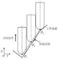
对于刀具抬升距离的计算,以刀具内部中单个离散特征点为例,如图11所示,首先计算以该点为起点,沿刀轴反方向的射线与刀具底面的交点,并计算射线起点到交点的距离l,刀具沿刀轴方向抬升距离l即可避免刀具对该点的过切。对于刀具内部的其他特征点均按此方法计算抬升距离l,并取最大值作为刀具在此处的最终抬升距离。For the calculation of the tool lifting distance, take a single discrete feature point inside the tool as an example, as shown in Figure 11, first calculate the intersection of the ray along the opposite direction of the tool axis and the bottom surface of the tool with this point as the starting point, and calculate the starting point of the ray to the bottom surface of the tool. The distance l of the intersection point, and the tool is lifted along the tool axis direction by a distance l to avoid overcutting of the point by the tool. For other feature points inside the tool, the lifting distance l is calculated according to this method, and the maximum value is taken as the final lifting distance of the tool here.
然而,在计算沿刀轴反方向的射线与刀具底面交点时,因刀具底面为三维空间的曲面,且不同类型的刀具其底面不一致。如平底刀底面为平面;球头铣刀底面为球面;锥度球头铣刀底面为球面和锥形面的组合。因此计算射线与刀具底面交点的过程较复杂。为简化这一过程,这里首先将刀具内部的特征点均绕刀轴旋转至一固定平面;然后计算出刀具在这一固定平面上的轮廓曲线;最后在该固定平面上计算以特征点为起点沿刀轴反方向的射线与刀具轮廓曲线的交点,并计算起点到交点的距离。如此将原先三维空间的线与曲面的求交转化为二维平面内的线与曲线的求交。However, when calculating the intersection of the ray along the opposite direction of the tool axis and the bottom surface of the tool, the bottom surface of the tool is a curved surface in three-dimensional space, and the bottom surfaces of different types of tools are inconsistent. For example, the bottom surface of a flat-bottomed cutter is a plane; the bottom surface of a ball-end milling cutter is a spherical surface; the bottom surface of a tapered ball-end milling cutter is a combination of a spherical surface and a conical surface. Therefore, the process of calculating the intersection of the ray and the bottom surface of the tool is more complicated. In order to simplify this process, firstly rotate the feature points inside the tool to a fixed plane around the tool axis; then calculate the contour curve of the tool on this fixed plane; finally, calculate the feature point on the fixed plane as the starting point. The intersection of the ray in the opposite direction of the tool axis and the tool contour curve, and the distance from the starting point to the intersection is calculated. In this way, the intersection of the line and the curved surface in the original three-dimensional space is transformed into the intersection of the line and the curve in the two-dimensional plane.
具体如图10所示,在刀具位置建立刀具坐标系OTXTYTZT,刀具刀尖位置为坐标系原点,ZT与刀轴方向一致。以刀具坐标系的YTOTZT平面为固定平面,首先将刀具内部的特征点Qi绕刀轴旋转至YTOTZT平面中得到点Gi。然后计算以点Gi为起点的刀轴反方向射线与刀具在YTOTZT平面上的二维轮廓曲线的交点,并计算起点与交点之间的距离li,若将刀具沿刀轴抬升li即可避免对Qi的过切,如图11所示。Specifically, as shown in Figure 10, the tool coordinate system OT XT YT ZT is established at the tool position, the tool nose position is the origin of the coordinate system, and ZT is consistent with the direction of the tool axis. Taking the YT OT ZT plane of the tool coordinate system as the fixed plane, firstly, the feature point Qi inside the tool is rotated around the tool axis to the YT OT ZT plane to obtain the point Gi . Then calculate the intersection point of the ray in the opposite direction of the tool axis starting from the pointGi and the two-dimensional contour curve of the tool on the YT OT ZT plane, and calculate the distance li between the starting point and the intersection point. Theovercut of Qi can be avoided by raising the shaftli , as shown in Figure 11.
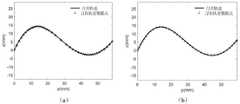
图12为一组初始刀具轨迹与优化后的无过切刀具轨迹的对比,可见无过切刀具轨迹中刀具均与工件表面相切于一点,避免了原刀具轨迹中的局部过切。其中图12(a)为初始刀具轨迹,图12(b)为无过切刀具轨迹。Figure 12 shows the comparison between a set of initial tool paths and the optimized non-overcut tool path. It can be seen that the tools in the non-overcut tool path are all tangent to the workpiece surface at one point, avoiding local overcut in the original tool path. Fig. 12(a) is the initial tool path, and Fig. 12(b) is the tool path without overcut.
另外,在实际加工中,数控系统是控制刀具沿刀具轨迹逐点运动,这些点即为刀位点。因此,采用上述方法计算无过切刀具轨迹时,若刀具轨迹中相邻点之间的距离过长,如图13所示,在完成无过切刀具轨迹计算后,刀具轨迹中相邻两点P1和P2,虽已抬升至无过切位置,但刀具在运动至两者之间的P3点时,仍与工件表面存在局部过切。In addition, in actual processing, the numerical control system controls the tool to move point by point along the tool path, and these points are the tool position points. Therefore, when the above method is used to calculate the tool path without overcut, if the distance between adjacent points in the tool path is too long, as shown in Figure 13, after the calculation of the tool path without overcut is completed, two adjacent points in the tool path Although P1 and P2 have been raised to the position without overcut, when the tool moves to the point P3 between them, there is still partial overcut with the workpiece surface.
为实现刀具轨迹中相邻点之间的距离可控,本发明提出了等距插值的方法,主要思路为:In order to realize the controllable distance between adjacent points in the tool path, the present invention proposes a method for equidistant interpolation. The main idea is as follows:
(1)以刀具轨迹的起点为圆心,以设定步长为半径作圆,计算刀具轨迹中与该圆存在交点的相邻两点连线,并以交点为分割点,将刀具轨迹分为前后两段。(1) Take the starting point of the tool path as the center of the circle and the set step size as the radius to make a circle, calculate the line connecting the two adjacent points in the tool path that intersect the circle, and take the intersection point as the dividing point to divide the tool path into two parts. Two paragraphs before and after.
具体如图14所示,刀具轨迹的起点为点P1,首先以点P1为圆心,以设定步长r为半径作圆,计算刀具轨迹中与该圆存在交点的相邻两点连线,并以交点坐标为分割点,将刀具轨迹分为前后两段。Specifically, as shown in Fig. 14, the starting point of the tool path is point P1 . First, take point P1 as the center of the circle and set the step size r as the radius to make a circle, and calculate the connection between the two adjacent points in the tool path that intersect the circle. Line, and take the intersection coordinates as the dividing point to divide the tool path into two sections.
(2)以后面一段刀具轨迹的起点为圆心,继续以设定步长r为半径作圆,计算刀具轨迹中与该圆存在交点的相邻两点连线,然后计算圆与两点连线的交点坐标,并以该坐标为分割点,将刀具轨迹分为前后两段。(2) Take the starting point of the following tool path as the center of the circle, continue to make a circle with the set step size r as the radius, calculate the connection between the two adjacent points in the tool path that intersect the circle, and then calculate the connection between the circle and the two points The coordinate of the intersection point, and the coordinate is used as the dividing point to divide the tool path into two sections.
(3)重复以上步骤,直至在以后面一段刀具轨迹的起点为圆心作半径为设定步长r的圆时,刀具轨迹中无相邻两点连线与该圆存在交点。(3) Repeat the above steps until the circle with the radius of the set step r is made with the starting point of the following tool path as the center, and there is no intersection between the line connecting two adjacent points in the tool path and the circle.
这个过程中的交点即为刀具轨迹的等距插值点,即刀位点。图15为上述等距插值方法的实例与未采用等距插值的刀具轨迹对比图,其中图15(a)为原刀具轨迹示意图,图15(b)为等距插值后刀具轨迹示意图。The intersection point in this process is the equidistant interpolation point of the tool path, that is, the tool position point. Fig. 15 is a comparison diagram of the example of the above-mentioned equidistant interpolation method and the tool path without equidistant interpolation, wherein Fig. 15(a) is a schematic diagram of the original tool path, and Fig. 15(b) is a schematic diagram of the tool path after equidistant interpolation.
以上所述,仅是本发明的较佳实施例而已,并非对本发明的技术范围作任何限制,故但凡依本发明的权利要求和说明书所做的变化或修饰,皆应属于本发明专利涵盖的范围之内。The above are only preferred embodiments of the present invention, and do not limit the technical scope of the present invention. Therefore, any changes or modifications made according to the claims and descriptions of the present invention shall be covered by the patent of the present invention. within the range.
Claims (6)
Priority Applications (1)
| Application Number | Priority Date | Filing Date | Title |
|---|---|---|---|
| CN202210609329.2ACN115185236A (en) | 2022-05-31 | 2022-05-31 | A tool path planning method to avoid tool overcut |
Applications Claiming Priority (1)
| Application Number | Priority Date | Filing Date | Title |
|---|---|---|---|
| CN202210609329.2ACN115185236A (en) | 2022-05-31 | 2022-05-31 | A tool path planning method to avoid tool overcut |
Publications (1)
| Publication Number | Publication Date |
|---|---|
| CN115185236Atrue CN115185236A (en) | 2022-10-14 |
Family
ID=83514118
Family Applications (1)
| Application Number | Title | Priority Date | Filing Date |
|---|---|---|---|
| CN202210609329.2APendingCN115185236A (en) | 2022-05-31 | 2022-05-31 | A tool path planning method to avoid tool overcut |
Country Status (1)
| Country | Link |
|---|---|
| CN (1) | CN115185236A (en) |
Cited By (3)
| Publication number | Priority date | Publication date | Assignee | Title |
|---|---|---|---|---|
| CN116834089A (en)* | 2023-04-18 | 2023-10-03 | 武汉工程大学 | Posture track calculation method for recessive tooth socket cutting and tooth socket cutting tool |
| CN119152159A (en)* | 2024-10-10 | 2024-12-17 | 南京衍构科技有限公司 | 3D printing rotating curved surface slicing method, system, equipment and storage medium |
| CN119937464A (en)* | 2025-01-20 | 2025-05-06 | 浙江大学 | A four-axis rough machining method for cylindrical parts based on discrete subdivision slicing |
Citations (7)
| Publication number | Priority date | Publication date | Assignee | Title |
|---|---|---|---|---|
| CN102520671A (en)* | 2011-11-24 | 2012-06-27 | 西安陕鼓动力股份有限公司 | Preprocessing determination method of excessive turning problem of numeric-control milling axial flow compressor blade |
| CN103135446A (en)* | 2011-12-05 | 2013-06-05 | 中国科学院沈阳计算技术研究所有限公司 | Motion trail authentication device of multiaxis numerical control machine tool |
| CN105739432A (en)* | 2016-03-17 | 2016-07-06 | 浙江大学 | Grid free-form surface toroidal cutter path planning method based on improved Butterfly subdivision |
| JP2016162149A (en)* | 2015-02-28 | 2016-09-05 | 国立大学法人神戸大学 | Cutting force adaptive control method and cutting force adaptive control system |
| CN106200551A (en)* | 2016-08-02 | 2016-12-07 | 南京航空航天大学 | Elliptical vibration method for controlling trajectory based on micro-texture model |
| CN109570591A (en)* | 2019-01-08 | 2019-04-05 | 湘潭大学 | Centrifugal impeller cutting working method and device and centrifugal impeller process equipment |
| CN114282376A (en)* | 2021-12-27 | 2022-04-05 | 含光微纳科技(深圳)有限公司 | NC code detection method, device and intelligent terminal based on anti-collision and overcut |
- 2022
- 2022-05-31CNCN202210609329.2Apatent/CN115185236A/enactivePending
Patent Citations (7)
| Publication number | Priority date | Publication date | Assignee | Title |
|---|---|---|---|---|
| CN102520671A (en)* | 2011-11-24 | 2012-06-27 | 西安陕鼓动力股份有限公司 | Preprocessing determination method of excessive turning problem of numeric-control milling axial flow compressor blade |
| CN103135446A (en)* | 2011-12-05 | 2013-06-05 | 中国科学院沈阳计算技术研究所有限公司 | Motion trail authentication device of multiaxis numerical control machine tool |
| JP2016162149A (en)* | 2015-02-28 | 2016-09-05 | 国立大学法人神戸大学 | Cutting force adaptive control method and cutting force adaptive control system |
| CN105739432A (en)* | 2016-03-17 | 2016-07-06 | 浙江大学 | Grid free-form surface toroidal cutter path planning method based on improved Butterfly subdivision |
| CN106200551A (en)* | 2016-08-02 | 2016-12-07 | 南京航空航天大学 | Elliptical vibration method for controlling trajectory based on micro-texture model |
| CN109570591A (en)* | 2019-01-08 | 2019-04-05 | 湘潭大学 | Centrifugal impeller cutting working method and device and centrifugal impeller process equipment |
| CN114282376A (en)* | 2021-12-27 | 2022-04-05 | 含光微纳科技(深圳)有限公司 | NC code detection method, device and intelligent terminal based on anti-collision and overcut |
Cited By (4)
| Publication number | Priority date | Publication date | Assignee | Title |
|---|---|---|---|---|
| CN116834089A (en)* | 2023-04-18 | 2023-10-03 | 武汉工程大学 | Posture track calculation method for recessive tooth socket cutting and tooth socket cutting tool |
| CN119152159A (en)* | 2024-10-10 | 2024-12-17 | 南京衍构科技有限公司 | 3D printing rotating curved surface slicing method, system, equipment and storage medium |
| CN119152159B (en)* | 2024-10-10 | 2025-03-11 | 南京衍构科技有限公司 | 3D printing rotating curved surface slicing method, system, equipment and storage medium |
| CN119937464A (en)* | 2025-01-20 | 2025-05-06 | 浙江大学 | A four-axis rough machining method for cylindrical parts based on discrete subdivision slicing |
Similar Documents
| Publication | Publication Date | Title |
|---|---|---|
| CN115185236A (en) | A tool path planning method to avoid tool overcut | |
| Lee et al. | Surface interrogation and machining strip evaluation for 5-axis CNC die and mold machining | |
| Lasemi et al. | Recent development in CNC machining of freeform surfaces: A state-of-the-art review | |
| CN102473008B (en) | Automatic programming device and method | |
| Li et al. | Interference-free inspection path generation for impeller blades using an on-machine probe | |
| CN109343468B (en) | A method for generating multi-axis trajectory of blade based on projection offset | |
| CN102621928B (en) | Method for generating pose angle feasible regions of five-axis tools quickly | |
| CN109597354B (en) | A multi-constraint NC machining trajectory generation method for triangular mesh model | |
| CN107407927A (en) | Orbit calculation program, processing device, orbit calculation method, tool, and processed article | |
| CN111459097A (en) | A Calculation Method for Surface Machining Contact Area of Ball End Milling Cutter | |
| Chu et al. | An integrated framework of tool path planning in 5-axis machining of centrifugal impeller with split blades | |
| Zhang et al. | Automatic sweep scan path planning for five-axis free-form surface inspection based on hybrid swept area potential field | |
| CN112613150A (en) | Image expression method of cutting geometry | |
| Lasemi et al. | A freeform surface manufacturing approach by integration of inspection and tool path generation | |
| CN106334972A (en) | A Kind of Edge Contact Criterion Method for Plane Machining with Ball End Milling Cutter | |
| CN117371137A (en) | Multi-axis milling surface morphology rapid prediction method for ball end mill based on SQP | |
| CN106406237A (en) | Method for processing metal part with free-form hook surface | |
| CN113204852A (en) | Method and system for predicting milling surface appearance of ball-end milling cutter | |
| KR20250010648A (en) | Systems and methods for surface fitting, path planning and surface treatment of objects | |
| Jensen et al. | A review of numerically controlled methods for finish-sculptured-surface machining | |
| CN110727246B (en) | Tool and workpiece instantaneous contact contour extraction method based on tool position file | |
| Yin | A partitioning grinding method for complex-shaped stone based on surface machining complexity | |
| CN115167275A (en) | Non-interference cutter shaft direction obtaining method and cutter path planning method | |
| CN107544433A (en) | Five-axle number control machine tool plane machining process rose cutter and workpiece contact zone semi analytic modeling method | |
| CN110497727A (en) | An Optimal Processing Space Selection Method for Three-dimensional Stone Sculpture Processing |
Legal Events
| Date | Code | Title | Description |
|---|---|---|---|
| PB01 | Publication | ||
| PB01 | Publication | ||
| SE01 | Entry into force of request for substantive examination | ||
| SE01 | Entry into force of request for substantive examination |